WO2024070708A1 - 二次電池用負極材料および二次電池 - Google Patents
二次電池用負極材料および二次電池 Download PDFInfo
- Publication number
- WO2024070708A1 WO2024070708A1 PCT/JP2023/033413 JP2023033413W WO2024070708A1 WO 2024070708 A1 WO2024070708 A1 WO 2024070708A1 JP 2023033413 W JP2023033413 W JP 2023033413W WO 2024070708 A1 WO2024070708 A1 WO 2024070708A1
- Authority
- WO
- WIPO (PCT)
- Prior art keywords
- phosphate
- silicon
- negative electrode
- phase
- electrode material
- Prior art date
- Legal status (The legal status is an assumption and is not a legal conclusion. Google has not performed a legal analysis and makes no representation as to the accuracy of the status listed.)
- Ceased
Links
Images
Classifications
-
- H—ELECTRICITY
- H01—ELECTRIC ELEMENTS
- H01M—PROCESSES OR MEANS, e.g. BATTERIES, FOR THE DIRECT CONVERSION OF CHEMICAL ENERGY INTO ELECTRICAL ENERGY
- H01M4/00—Electrodes
- H01M4/02—Electrodes composed of, or comprising, active material
- H01M4/36—Selection of substances as active materials, active masses, active liquids
- H01M4/362—Composites
- H01M4/366—Composites as layered products
-
- H—ELECTRICITY
- H01—ELECTRIC ELEMENTS
- H01M—PROCESSES OR MEANS, e.g. BATTERIES, FOR THE DIRECT CONVERSION OF CHEMICAL ENERGY INTO ELECTRICAL ENERGY
- H01M4/00—Electrodes
- H01M4/02—Electrodes composed of, or comprising, active material
- H01M4/13—Electrodes for accumulators with non-aqueous electrolyte, e.g. for lithium-accumulators; Processes of manufacture thereof
- H01M4/134—Electrodes based on metals, Si or alloys
-
- H—ELECTRICITY
- H01—ELECTRIC ELEMENTS
- H01M—PROCESSES OR MEANS, e.g. BATTERIES, FOR THE DIRECT CONVERSION OF CHEMICAL ENERGY INTO ELECTRICAL ENERGY
- H01M4/00—Electrodes
- H01M4/02—Electrodes composed of, or comprising, active material
- H01M4/36—Selection of substances as active materials, active masses, active liquids
- H01M4/362—Composites
- H01M4/364—Composites as mixtures
-
- H—ELECTRICITY
- H01—ELECTRIC ELEMENTS
- H01M—PROCESSES OR MEANS, e.g. BATTERIES, FOR THE DIRECT CONVERSION OF CHEMICAL ENERGY INTO ELECTRICAL ENERGY
- H01M4/00—Electrodes
- H01M4/02—Electrodes composed of, or comprising, active material
- H01M4/36—Selection of substances as active materials, active masses, active liquids
- H01M4/38—Selection of substances as active materials, active masses, active liquids of elements or alloys
- H01M4/386—Silicon or alloys based on silicon
-
- H—ELECTRICITY
- H01—ELECTRIC ELEMENTS
- H01M—PROCESSES OR MEANS, e.g. BATTERIES, FOR THE DIRECT CONVERSION OF CHEMICAL ENERGY INTO ELECTRICAL ENERGY
- H01M4/00—Electrodes
- H01M4/02—Electrodes composed of, or comprising, active material
- H01M4/62—Selection of inactive substances as ingredients for active masses, e.g. binders, fillers
- H01M4/621—Binders
- H01M4/622—Binders being polymers
- H01M4/623—Binders being polymers fluorinated polymers
-
- H—ELECTRICITY
- H01—ELECTRIC ELEMENTS
- H01M—PROCESSES OR MEANS, e.g. BATTERIES, FOR THE DIRECT CONVERSION OF CHEMICAL ENERGY INTO ELECTRICAL ENERGY
- H01M4/00—Electrodes
- H01M4/02—Electrodes composed of, or comprising, active material
- H01M4/62—Selection of inactive substances as ingredients for active masses, e.g. binders, fillers
- H01M4/628—Inhibitors, e.g. gassing inhibitors, corrosion inhibitors
-
- H—ELECTRICITY
- H01—ELECTRIC ELEMENTS
- H01M—PROCESSES OR MEANS, e.g. BATTERIES, FOR THE DIRECT CONVERSION OF CHEMICAL ENERGY INTO ELECTRICAL ENERGY
- H01M10/00—Secondary cells; Manufacture thereof
- H01M10/05—Accumulators with non-aqueous electrolyte
- H01M10/052—Li-accumulators
-
- H—ELECTRICITY
- H01—ELECTRIC ELEMENTS
- H01M—PROCESSES OR MEANS, e.g. BATTERIES, FOR THE DIRECT CONVERSION OF CHEMICAL ENERGY INTO ELECTRICAL ENERGY
- H01M4/00—Electrodes
- H01M4/02—Electrodes composed of, or comprising, active material
- H01M2004/026—Electrodes composed of, or comprising, active material characterised by the polarity
- H01M2004/027—Negative electrodes
-
- Y—GENERAL TAGGING OF NEW TECHNOLOGICAL DEVELOPMENTS; GENERAL TAGGING OF CROSS-SECTIONAL TECHNOLOGIES SPANNING OVER SEVERAL SECTIONS OF THE IPC; TECHNICAL SUBJECTS COVERED BY FORMER USPC CROSS-REFERENCE ART COLLECTIONS [XRACs] AND DIGESTS
- Y02—TECHNOLOGIES OR APPLICATIONS FOR MITIGATION OR ADAPTATION AGAINST CLIMATE CHANGE
- Y02E—REDUCTION OF GREENHOUSE GAS [GHG] EMISSIONS, RELATED TO ENERGY GENERATION, TRANSMISSION OR DISTRIBUTION
- Y02E60/00—Enabling technologies; Technologies with a potential or indirect contribution to GHG emissions mitigation
- Y02E60/10—Energy storage using batteries
Definitions
- This disclosure relates to negative electrode materials for secondary batteries and secondary batteries.
- Secondary batteries such as lithium-ion secondary batteries, are used as power sources for electronic devices such as mobile terminals, and as power sources for vehicles such as electric cars.
- a negative electrode active material capable of absorbing and releasing lithium ions is used for the negative electrode of a secondary battery, and graphite is generally used as such a negative electrode active material.
- Patent Document 1 proposes a negative electrode active material for secondary batteries that includes a silicate phase containing Li, Si, and Mx (Mx is an element other than an alkali metal, an alkaline earth metal, or Si), silicon particles dispersed in the silicate phase, and metal particles dispersed in the silicate phase, the main component of which is one or more metals or alloys selected from Fe, Cr, Ni, Mn, Cu, Mo, Zn, and Al, in which the content of each element relative to the total of elements other than oxygen in the silicate phase is 3 to 45 mol % for Li, 40 to 78 mol % for Si, and 1 to 40 mol % for Mx.
- Mx is an element other than an alkali metal, an alkaline earth metal, or Si
- Si silicon particles dispersed in the silicate phase
- metal particles dispersed in the silicate phase the main component of which is one or more metals or alloys selected from Fe, Cr, Ni, Mn, Cu, Mo, Zn, and Al, in which the
- Patent Document 2 proposes a negative electrode active material for secondary batteries, which comprises a silicate phase containing Li, Si, and Mx (Mx is an element other than an alkali metal, an alkaline earth metal, or Si), silicon particles dispersed in the silicate phase, and oxide particles containing at least one of oxide particles containing Zr, oxide particles containing Ce, oxide particles containing Ca, oxide particles containing Al, oxide particles containing Fe, oxide particles containing Mg, oxide particles containing Ti, and oxide particles containing W dispersed in the silicate phase, in which the content of each element relative to the total of elements other than oxygen in the silicate phase is 3 to 45 mol % for Li, 40 to 78 mol % for Si, and 1 to 40 mol % for Mx.
- Mx is an element other than an alkali metal, an alkaline earth metal, or Si
- one aspect of the present disclosure relates to a negative electrode material for a secondary battery, comprising silicon-containing particles and a coating layer covering at least a portion of the surface of the silicon-containing particles, the coating layer including a phosphate compound and a hydrophobic polymer compound.
- a negative electrode material for a secondary battery comprising silicon-containing particles and a coating layer covering at least a portion of the surface of the silicon-containing particles, the coating layer including a phosphate compound and a water-insoluble polymer compound.
- Another aspect of the present disclosure relates to a secondary battery comprising a positive electrode, a negative electrode, and an electrolyte, the negative electrode including the above-mentioned negative electrode material for secondary batteries.
- FIG. 1 is a cross-sectional view illustrating a schematic diagram of a negative electrode material for a secondary battery according to an embodiment of the present disclosure.
- FIG. 1 is a schematic perspective view of a secondary battery according to an embodiment of the present disclosure, with a portion cut away.
- the present disclosure encompasses a combination of the features described in two or more claims arbitrarily selected from the multiple claims described in the appended claims.
- the features described in two or more claims arbitrarily selected from the multiple claims described in the appended claims may be combined, provided that no technical contradiction arises.
- the negative electrode material for a secondary battery includes silicon-containing particles (Si-based active material) and a coating layer that covers at least a part of the surface of the silicon-containing particles.
- the coating layer includes a phosphate compound and a hydrophobic polymer compound.
- the silicon-containing particles are preferably composite particles containing an ion-conducting phase and a silicon phase dispersed within the ion-conducting phase.
- the ion-conducting phase may contain, for example, at least one selected from the group consisting of a silicate phase, a silicon oxide phase, and a carbon phase.
- silicate phase and the silicon oxide phase are also referred to as a "silicon compound phase.”
- Composite particles in which a silicon phase is dispersed within a silicate phase are also referred to as “silicon phase-containing composite particles.”
- Composite particles in which a silicon phase is dispersed within a silicon oxide phase are also referred to as “silicon oxide phase-containing composite particles.”
- Composite particles in which a silicon phase is dispersed within a carbon phase are also referred to as "carbon phase-containing composite particles.”
- the silicon-containing particles are protected from the electrolyte, side reactions with the electrolyte are suppressed, and deterioration of cycle characteristics caused by the side reactions is suppressed.
- the coating layer contains a hydrophobic polymer along with the phosphate compound. This improves the retention of the phosphate compound on the surface of the silicon-containing particles, and the surface of the silicon-containing particles is effectively coated with the phosphate compound. As a result, the protective effect of the phosphate compound on the silicon-containing particles (in the case of composite particles, the effect of inhibiting erosion of the ion-conducting phase) is significantly achieved. As a result, the cycle characteristics can be significantly improved.
- the negative electrode is produced, for example, by preparing a slurry containing the negative electrode material and water, applying the slurry to the negative electrode current collector, drying it, and rolling it as necessary to form a negative electrode mixture layer.
- the presence of a hydrophobic polymer compound on the surface of the negative electrode material suppresses the dissolution of the phosphate compound in water when preparing the slurry containing water. It is desirable for the hydrophobic polymer compound to be a material that combines excellent binding properties and hydrophobicity.
- the coating layer may contain a certain amount of a mixture of phosphate compounds and hydrophobic polymer compounds.
- the coating layer may be composed of a layer of phosphate compounds and a layer of hydrophobic polymer compounds formed on the layer of phosphate compounds. From the viewpoint of facilitating improved retention of the phosphate compounds, the content of the hydrophobic polymer compounds may be greater in the surface layer than in the inner layer of the coating layer.
- the surface layer of the coating layer refers to a region that is located at a distance from the outermost surface of the coating layer that is equal to or less than 1/2 the thickness of the coating layer.
- the inner layer of the coating layer refers to a region that is located at a distance from the outermost surface of the coating layer that is greater than 1/2 the thickness of the coating layer.
- the coating layer containing a phosphate compound has low resistance and good ionic conductivity.
- the cation includes a metal ion, an ammonium ion ( NH4 + ), etc.
- the PO structure may constitute a PO3 structure.
- the PO3 structure may be contained in a polyanion such as PO33- , HPO32- , or H2PO3- .
- XPS X-ray photoelectron spectroscopy
- Metals that can form cations in phosphate compounds include alkali metals, beryllium, magnesium, alkaline earth metals, transition metals, aluminum, etc.
- Alkaline metals include sodium and potassium.
- Alkaline earth metals include calcium.
- Transition metals include iron, manganese, nickel, etc.
- the phosphate compound may be an inorganic phosphate compound or an organic phosphate compound.
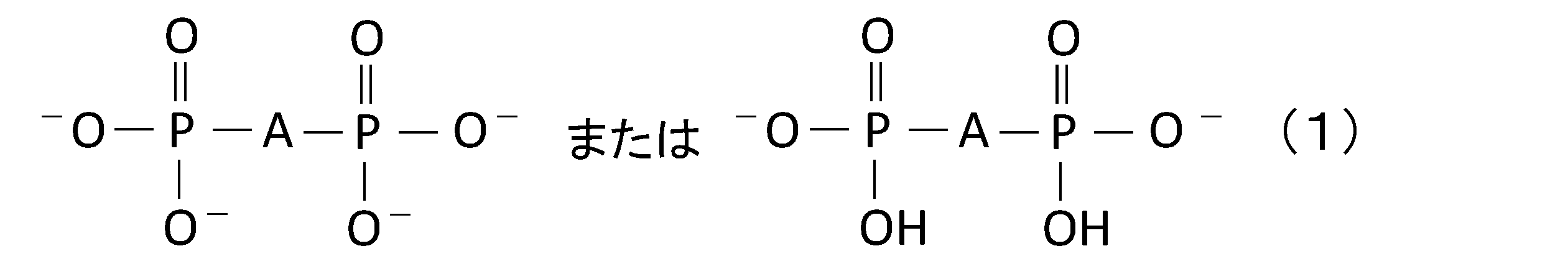
- Phosphate compounds have the general formula (1):
- the compound contains at least one selected from the group consisting of a phosphate compound, a polyphosphate compound, and a metaphosphate compound containing an anion represented by the general formula (1).
- A is an organic group or an oxygen atom.
- the two phosphorus atoms in the anion represented by the general formula (1) are bonded via a carbon atom.
- the above phosphate compound contains an anion having multiple PO structures, and such a phosphate compound can react with decomposition products of the electrolyte (e.g., HF) to form a flexible polymer on the surface or inside of the coating layer.
- a coating layer containing such a polymer easily follows the expansion and contraction of the silicon-containing particles, and the protective effect of the coating layer on the silicon-containing particles is firmly maintained during charge/discharge cycles. In addition, isolation of particles due to particle cracking is also suppressed. Furthermore, a coating layer containing the polymer has low resistance and good ionic conductivity.
- the above phosphate compound has multiple PO structures, has good affinity with water, and has excellent dispersibility in water.
- the phosphate compound is dispersed in water and mixed with the silicon-containing particles, so that the surfaces of the silicon-containing particles are easily covered uniformly with the phosphate compound, and the coverage of the phosphate compound is improved.
- the coating layer may contain at least one of a phosphate compound containing one anion represented by general formula (1) and a cation, and a phosphate compound containing the other anion represented by general formula (1) and a cation.
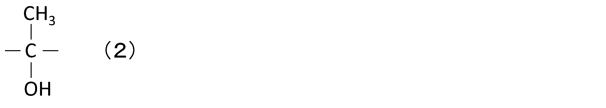
- A is an organic group, and the organic group is represented by formula (2):
- the phosphate compound containing the anion represented by the general formula (1) is an etidronate.
- etidronate include disodium etidronate (C 2 H 6 Na 2 O 7 P 2 ), tetrasodium etidronate (C 2 H 4 Na 4 O 7 P 2 ), etc.
- Phosphate compounds containing an anion represented by general formula (1), in which A in general formula (1) is an organic group, include, in addition to etidronate, clodronate, tiludronate, etc.
- a phosphate compound containing an anion represented by the general formula (1) in which A is an oxygen atom is a pyrophosphate.
- pyrophosphate include sodium pyrophosphate (Na4P2O7 ) , potassium pyrophosphate ( K4P2O7 ), calcium pyrophosphate (Ca2P2O7 ) , and ferric pyrophosphate ( Fe4 ( P2O7 ) 3 ).
- the polyphosphate compound includes at least one selected from the group consisting of tripolyphosphate and tetrapolyphosphate.
- tripolyphosphate examples include sodium tripolyphosphate (Na 5 P 3 O 10 ).
- tetrapolyphosphate examples include sodium tetrapolyphosphate (Na 6 P 4 O 13 ).
- the metaphosphate compound includes at least one selected from the group consisting of, for example, trimetaphosphate and hexametaphosphate.
- trimetaphosphate include sodium trimetaphosphate (( NaPO3 ) 3 ), potassium trimetaphosphate (( KPO3 ) 3 ), etc.
- hexametaphosphate include sodium hexametaphosphate (( NaPO3 ) 6 ), potassium hexametaphosphate (( KPO3 ) 6 ), etc.
- etidronate is preferred as the phosphate compound, from the viewpoint that a flexible polymer derived from the phosphate compound is easily formed in the coating layer, and the protective effect of the coating layer on the silicon-containing particles is more firmly maintained during charge/discharge cycles.
- Etidronic acid salts have many hydroxyl groups, good affinity with water, and are also preferred from the viewpoint of improving dispersibility in water.
- the phosphate compound may be an inorganic phosphoric acid salt containing an anion of PO 4 3 ⁇ , HPO 4 2 ⁇ , or H 2 PO 4 ⁇ and a cation.
- phosphate compounds include monosodium phosphate, disodium phosphate, trisodium phosphate, monopotassium phosphate, dipotassium phosphate, tripotassium phosphate, trilithium phosphate, LiH 2 PO 4 , monoammonium phosphate, diammonium phosphate, triammonium phosphate, monocalcium phosphate, dicalcium phosphate, tricalcium phosphate, monomagnesium phosphate, dimagnesium phosphate, trimagnesium phosphate, monoaluminum phosphate, dialuminum phosphate, trialuminum phosphate, manganese biphosphate, zinc phosphate, and boron phosphate.
- the amount of phosphate compound covering the surface of the silicon-containing particle (hereinafter also referred to as the amount of phosphate compound carried) may be 1 part by mass or more (or 2 parts by mass) relative to 100 parts by mass of the silicon-containing particle, or it may be 1 part by mass or more and 10 parts by mass or less, or it may be 5 parts by mass or more and 10 parts by mass or less.
- the amount of the phosphate compound supported is 1 part by mass or more, the surface of the silicon-containing particles can be sufficiently coated with the phosphate compound, and the effect of suppressing side reactions caused by the phosphate compound is easily obtained.
- the larger the amount of the phosphate compound supported is within the range of 1 part by mass or more and 10 parts by mass or less, the easier it is to improve the cycle characteristics.
- the amount of the phosphate compound supported is 10 parts by mass or less, a low-resistance negative electrode material (coating layer) is easily obtained.
- the thickness of the coating layer is preferably thin enough that it does not substantially affect the average particle size of the silicon-containing particles. From the viewpoint of protecting the silicon-containing particles from the electrolyte, the thickness of the coating layer is preferably 1 nm or more. From the viewpoint of suppressing an increase in resistance, the thickness of the coating layer is preferably 300 nm or less. The thickness of the coating layer may be smaller than the thickness of the conductive layer described below. The thickness of the coating layer can be measured by observing the cross section of the silicon-containing particles using an electron microscope. The electron microscope used is a scanning electron microscope (SEM) or a transmission electron microscope (TEM).
- SEM scanning electron microscope
- TEM transmission electron microscope
- the phosphate compounds contained in the coating layer of the negative electrode material can be identified, for example, by time-of-flight secondary ion mass spectrometry (TOF-SIMS). Ions derived from the phosphate compounds are detected in the coating layer.
- TOF-SIMS time-of-flight secondary ion mass spectrometry
- the hydrophobic polymer compound preferably has good binding properties and heat melting properties.
- the hydrophobic polymer compound can firmly support the phosphate compound on the surface of the silicon-containing particle, and the effect of suppressing the side reaction caused by the phosphate compound can be stably obtained.
- the hydrophobic polymer compound is almost insoluble in water.
- the hydrophobic polymer compound preferably contains a fluororesin.
- the fluororesin preferably contains at least one selected from the group consisting of polyvinylidene fluoride (PVDF), polytetrafluoroethylene, tetrafluoroethylene-perfluoroalkyl vinyl ether copolymer, tetrafluoroethylene-hexafluoropropylene copolymer, tetrafluoroethylene-ethylene copolymer, chlorotrifluoroethylene-ethylene copolymer, and polychlorotrifluoroethylene.
- PVDF polyvinylidene fluoride
- PVDF polytetrafluoroethylene
- tetrafluoroethylene-perfluoroalkyl vinyl ether copolymer tetrafluoroethylene-hexafluoropropylene copolymer
- tetrafluoroethylene-ethylene copolymer chlorotrifluoroethylene-ethylene copolymer
- the hydrophobic polymer compound may include a polymer containing vinylidene fluoride units, in addition to polyvinylidene fluoride.
- polymers containing vinylidene fluoride units include copolymers of vinylidene fluoride with other monomers. Examples of other monomers include hexafluoropropylene (HFP) and tetrafluoroethylene (TFE).
- Polymers containing vinylidene fluoride units include polyvinylidene fluoride and its modified products, vinylidene fluoride-hexafluoropropylene copolymers, vinylidene fluoride-chlorotrifluoroethylene copolymers, etc.
- the content of vinylidene fluoride units is, for example, 30 mol% or more, and may be 50 mol% or more.
- the amount of hydrophobic polymer compound covering the surface of the silicon-containing particle may be 1 part by mass or more (or 2 parts by mass or more), 1 part by mass or more and 10 parts by mass or less, 1 part by mass or more and 6 parts by mass or less, or 2 parts by mass or more and 6 parts by mass or less, relative to 100 parts by mass of the silicon-containing particle.
- the hydrophobic polymer compound supported When the amount of the hydrophobic polymer compound supported is 1 part by mass or more, the hydrophobic polymer compound can sufficiently improve the retention of the phosphate compound on the surface of the silicon-containing particles. When the amount of the hydrophobic polymer compound supported is 6 parts by mass or less, a low-resistance negative electrode material (coating layer) is easily obtained.
- the amount of the phosphate compound and the fluororesin carried can be determined by the following method.
- the negative electrode material is washed with N-methyl-2-pyrrolidone (NMP) to dissolve the fluororesin, and the difference in mass of NMP before and after dissolution is calculated as the mass of the fluororesin.
- NMP N-methyl-2-pyrrolidone
- the remainder that does not dissolve in NMP is then washed with water to dissolve the phosphate compound.
- the mass of the phosphate compound dissolved in water is calculated using quantitative analysis such as inductively coupled plasma (ICP) emission spectrometry.
- ICP inductively coupled plasma
- the negative electrode material comprises composite particles containing a silicon compound phase (or particles of silicon alone or a silicon alloy)
- the remaining mass that does not dissolve in water and NMP is determined as the mass of the composite particles containing a silicon compound phase (or particles of silicon alone or a silicon alloy).
- the negative electrode material includes a silicon compound phase-containing composite particle having a conductive layer
- the remainder that is not dissolved in water and NMP is quantitatively analyzed for carbon using a carbon-sulfur analyzer or the like.
- the amount of carbon obtained is derived from the carbon material of the conductive layer.
- the mass of the silicon compound phase-containing composite particle is calculated by subtracting the mass of the remainder that is not dissolved in water and NMP from the mass of the carbon obtained by the analysis.
- the amount of the fluororesin supported is calculated by (mass of fluororesin/mass of silicon-containing particles) ⁇ 100.
- the amount of the phosphate compound supported is calculated by (mass of the phosphate compound/mass of the silicon-containing particles) ⁇ 100.
- the thickness of the coating layer is preferably thin enough that it does not substantially affect the average particle size of the silicon-containing particles. From the viewpoint of protecting the silicon-containing particles from the electrolyte, the thickness of the coating layer is preferably 1 nm or more. From the viewpoint of suppressing an increase in resistance, the thickness of the coating layer is preferably 300 nm or less. The thickness of the coating layer may be smaller than the thickness of the conductive layer described below. The thickness of the coating layer can be measured by observing the cross section of the silicon-containing particles using an electron microscope. The electron microscope used is a scanning electron microscope (SEM) or a transmission electron microscope (TEM).
- SEM scanning electron microscope
- TEM transmission electron microscope
- the conductivity may be relatively low depending on the components of the ion-conducting phase.
- a conductive layer containing a conductive carbon material may be interposed between the composite particle and the coating layer. That is, the coating layer may be formed so as to cover the conductive layer on the surface of the composite particle.
- the thickness of the conductive layer is preferably thin enough not to substantially affect the average particle size of the composite particle. From the viewpoint of ensuring the conductivity, the thickness of the conductive layer is preferably 1 nm or more. From the viewpoint of suppressing the increase in resistance, the total thickness of the coating layer and the conductive layer is preferably 300 nm or less. The thickness of the conductive layer can be measured in the same manner as in the case of the coating layer.
- the conductive layer is formed by mixing the raw material of the conductive carbon material with the composite particles, and then calcining the mixture to carbonize the raw material of the conductive carbon material.
- the raw material of the conductive material include coal pitch or coal tar pitch, petroleum pitch, and phenolic resin.
- the mixture of the raw material of the conductive carbon material and the composite particles is calcined, for example, in an inert atmosphere (for example, an atmosphere of argon, nitrogen, etc.).
- the calcination temperature is preferably 450°C or higher and 1000°C or lower. In the above temperature range, it is easy to form a highly conductive conductive layer in a silicate phase with low crystallinity.
- the calcination temperature is preferably 550°C or higher and 900°C or lower, and more preferably 650°C or higher and 850°C or lower.
- the calcination time is, for example, 1 hour or higher and 10 hours or lower.
- the method for producing the negative electrode material for a secondary battery includes, for example, the following first to third steps.
- Third step the second intermediate is heat-treated in an inert atmosphere, thereby forming a coating layer containing a phosphate compound and a hydrophobic polymer compound on the surface of the silicon-containing particle.
- the first and second steps may be carried out in the air, but are preferably carried out in an inert atmosphere.
- the phosphate compound and a solvent (dispersion medium) may be mixed, and then a solution (dispersion liquid) of the phosphate compound and the silicon-containing particles may be mixed.
- the solvent (dispersion medium) may be water, alcohol, or the like, and among these, water is preferred, since in this case the surfaces of the silicon-containing particles can be easily coated uniformly with the phosphate compound.
- the amount of the phosphate compound added in the first step may be 1 part by mass or more (or 2 parts by mass or more) and 10 parts by mass or less per 100 parts by mass of the silicon-containing particles.
- the dry mixing can be performed using a ball mill.
- the amount of the hydrophobic polymer compound added in the second step may be 1 part by mass or more (or 2 parts by mass or more) and 6 parts by mass or less based on 100 parts by mass of the silicon-containing particles.
- the second intermediate is heated to a temperature equal to or higher than the melting point of the hydrophobic polymer compound.
- the heat treatment step causes the hydrophobic polymer compound to be liquefied, and penetrates and diffuses around the silicon-containing particles and the particles of the phosphate compound so as to fill the gaps between the silicon-containing particles and the particles of the phosphate compound, and between the particles of the phosphate compound. This significantly improves the retention of the phosphate compound on the surface of the silicon-containing particles.
- the silicon-containing particles having a coating layer are obtained by crushing the heat-treated second intermediate. When the silicon-containing particles are composite particles having a conductive layer on the surface, a coating layer may be formed on the surface of the silicon-containing particles via the conductive layer.
- the heat treatment is desirably carried out at a temperature equal to or higher than the melting point of the hydrophobic polymer compound and equal to or lower than the decomposition temperature of the hydrophobic polymer compound.
- the heat treatment temperature may be equal to or higher than the melting point of PVDF (150°C to 170°C) and equal to or lower than the decomposition temperature (340°C), for example, 200°C to 250°C is preferable.
- the heat treatment may be carried out in an inert gas atmosphere.
- the heat treatment time may be, for example, about 1 to 3 hours.
- the above-mentioned method for producing a negative electrode material tends to form a coating layer in which the content of hydrophobic polymer compounds is greater in the surface layer than in the inner layer of the coating layer.
- XPS X-ray photoelectron spectroscopy
- TOF-SIMS time-of-flight secondary ion mass spectrometry
- the particle size of the phosphate compound added in the first step and the hydrophobic polymer compound added in the second step are preferably smaller than the particle size of the silicon-containing particles. In this case, it is easy to uniformly cover the surface of the silicon-containing particles (coating layer) with the phosphate compound and the hydrophobic polymer compound.
- the average particle size of the phosphate compound and the hydrophobic polymer compound may be 1 to 100 ⁇ m, or 1 to 10 ⁇ m, respectively.
- a negative electrode material for a secondary battery includes silicon-containing particles and a coating layer that covers at least a portion of the surface of the silicon-containing particles.
- the coating layer includes a phosphate compound and a water-insoluble polymer compound.
- the coating layer containing a phosphate compound and a water-insoluble polymer compound also provides the same effects as the coating layer containing a phosphate compound and a hydrophobic polymer compound.
- a coating layer containing a phosphate compound and a water-insoluble polymer compound By covering the surface of the silicon-containing particles with a coating layer containing a phosphate compound and a water-insoluble polymer compound, side reactions are suppressed, and the deterioration of cycle characteristics due to side reactions is suppressed.
- a water-insoluble polymer compound is one in which, for example, when 1 g of the polymer compound is added to 100 g of water at 25° C. and the water is thoroughly stirred, less than 0.02 g (or 0.01 g or less) of the polymer compound dissolves.
- water-insoluble polymer compounds include hydrophobic polymer compounds (e.g., fluororesins), as well as polymethyl methacrylate, polyethylene terephthalate, polybutylene terephthalate, polyacrylonitrile, polyimide, polyamide, polyethylene, polypropylene, polystyrene, polyvinyl chloride, and polycarbonate.
- the silicon-containing particle is a composite particle
- the surface of the composite particle is coated with a phosphate compound and a hydrophobic polymer compound, thereby protecting the composite particle from the electrolyte, suppressing side reactions with the electrolyte, and suppressing erosion of the ion-conducting phase due to the side reactions, thereby suppressing deterioration of the composite particle caused by the erosion and reducing the deterioration of the cycle characteristics.
- the composite particles have a structure in which a silicon phase is dispersed within an ion-conducting phase (matrix).
- the stress associated with the expansion and contraction of the silicon phase during charging and discharging is alleviated by the ion-conducting phase, suppressing cracking and fracture of the composite particles. This makes it possible to achieve both high capacity due to the inclusion of silicon and improved cycle characteristics.
- the ion-conducting phase may contain a silicon compound phase (at least one of a silicate phase and a silicon oxide phase) or a carbon phase.
- the ion-conducting phase may be composed of one phase or multiple phases.
- the silicon oxide phase is composed of a compound of Si and O.
- the main component of the silicon oxide phase (for example, 95 to 100% by mass) may be silicon dioxide.
- the silicate phase is composed of a compound containing a metal element, silicon (Si), and oxygen (O).
- the silicate phase preferably contains at least lithium silicate. In this case, lithium ions can easily enter and leave the silicate phase.
- the silicon oxide phase and the silicate phase those containing the silicate phase as the main component are preferred because of their small irreversible capacity.
- the "main component” refers to a component that occupies 50% by mass or more of the total mass of the silicon compound phase, and may occupy 70% by mass or more.
- the ion-conducting phase may be composed of a silicon compound phase, contain a lithium silicate phase as the main component, and contain a small amount of a silicon oxide phase.
- the composite particles may be composite particles containing a silicate phase and a silicon phase dispersed within the silicate phase (silicate phase-containing composite particles).
- the silicate phase-containing composite particles can be obtained, for example, by pulverizing a mixture of silicate and raw silicon while stirring in a ball mill or the like to form fine particles, heat-treating the mixture in an inert atmosphere, and pulverizing the sintered product obtained by the heat treatment.
- the silicate phase preferably contains at least one of an alkali metal element (a Group 1 element other than hydrogen in the long-form periodic table) and a Group 2 element in the long-form periodic table.
- Alkali metal elements include lithium (Li), potassium (K), sodium (Na), etc.
- Group 2 elements include magnesium (Mg), calcium (Ca), strontium (Sr), barium (Ba), etc.
- the silicate phase may further contain other elements such as rare earth elements such as lanthanum (La), aluminum (Al), and boron (B).
- Lithium silicate is a silicate containing lithium (Li), silicon (Si), and oxygen (O).
- the atomic ratio of O to Si in lithium silicate: O/Si is, for example, greater than 2 and less than 4 (z in the formula described below is 0 ⁇ z ⁇ 2).
- O/Si ratio is greater than 2 and less than 4
- the O/Si ratio is greater than 2 and equal to or less than 3.
- the atomic ratio of Li to Si in lithium silicate: Li/Si is, for example, greater than 0 and less than 4.
- the composition of lithium silicate can be expressed by the formula Li2zSiO2 +z (0 ⁇ z ⁇ 2). From the viewpoints of stability, ease of preparation, lithium ion conductivity , etc., 0 ⁇ z ⁇ 1 may also be acceptable.
- the average particle size of the fine silicon phase (before the first charge) dispersed within the silicate phase may be 500 nm or less, 200 nm or more, or 50 nm or less.
- the average particle size of the silicon phase is measured by observing the cross section of the negative electrode material using a SEM or TEM. Specifically, it is determined by averaging the maximum diameters of any 100 silicon phases.
- the silicon phase dispersed within the silicate phase is a particulate phase of simple silicon (Si) and is composed of one or more crystallites.
- the crystallite size of the silicon phase may be 5 nm or more and 50 nm or less. When the crystallite size of the silicon phase is 50 nm or less, the amount of volume change due to the expansion and contraction of silicon particles accompanying charging and discharging can be reduced, further improving cycle characteristics.
- the crystallite size of the silicon phase is calculated using the Scherrer formula from the half-width of the diffraction peak assigned to the Si (111) plane in the X-ray diffraction (XRD) pattern.
- the content of silicon phase in the silicate phase-containing composite particles may be 30% by mass or more and 90% by mass or less, or 35% by mass or more and 75% by mass or less.
- composition of the silicate phase-containing composite particles can be determined, for example, by the following analytical method.
- ⁇ EDX> From the cross-sectional image of the backscattered electron image of the negative electrode mixture layer, 10 composite particles with a maximum particle diameter of 5 ⁇ m or more are randomly selected, and elemental mapping analysis is performed on each of them using energy dispersive X-ray (EDX).
- the area ratio of the target element is calculated using image analysis software.
- the observation magnification is preferably 2000 to 20000 times.
- the measured values of the area ratio of a specific element contained in the 10 particles are averaged.
- the content of the target element is calculated from the obtained average value.
- ⁇ SEM-EDX measurement conditions > Processing equipment: JEOL, SM-09010 (Cross Section Polisher) Processing conditions: Acceleration voltage 6 kV Current value: 140 ⁇ A Degree of vacuum: 1 ⁇ 10 ⁇ 3 to 2 ⁇ 10 ⁇ 3 Pa Measuring device: HITACHI SU-70 electron microscope Acceleration voltage during analysis: 10 kV Field: Free mode Probe current mode: Medium Probe current range: High Anode Ap.: 3 OBJ Apr.: 2 Analysis area: 1 ⁇ m square Analysis software: EDAX Genesis CPS: 20500 Lsec: 50 Time constant: 3.2
- ⁇ AES> From the cross-sectional image of the backscattered electron image of the negative electrode mixture layer, 10 composite particles having a maximum particle diameter of 5 ⁇ m or more are randomly selected, and each is subjected to a qualitative and quantitative analysis of elements using an Auger electron spectroscopy (AES) analyzer (e.g., JAMP-9510F manufactured by JEOL Ltd.).
- AES Auger electron spectroscopy
- the measurement conditions may be, for example, an acceleration voltage of 10 kV, a beam current of 10 nA, and an analysis area of 20 ⁇ m ⁇ .
- the content of a predetermined element contained in the 10 particles is averaged to calculate the content.
- mapping analysis by EDX or AES is performed on a range 1 ⁇ m inside from the peripheral edge of the cross section of the composite particle so that the thin coating or conductive layer is not included in the measurement range.
- the mapping analysis can also confirm the distribution state of the carbon material inside the composite particle. It is preferable to measure a sample before or at the beginning of the cycle, since it becomes difficult to distinguish from the decomposition products of the electrolyte at the end of the cycle.
- ⁇ ICP> A sample of the composite particles is completely dissolved in a heated acid solution (a mixed acid of hydrofluoric acid, nitric acid, and sulfuric acid), and the carbon remaining in the solution is filtered off. The filtrate is then analyzed by inductively coupled plasma emission spectrometry (ICP) to measure the spectral intensity of each element. A calibration curve is then created using commercially available standard solutions of the elements, and the content of each element contained in the composite particles is calculated.
- ICP inductively coupled plasma emission spectrometry
- the contents of B, Na, K and Al contained in the silicate phase can be quantitatively analyzed in accordance with JIS R3105 (1995) (method of analysis of borosilicate glass).
- Silicate phase-containing composite particles contain a silicate phase and a silicon phase, which can be distinguished and quantified using Si-NMR.
- the Si content obtained by the above method is the sum of the amount of Si constituting the silicon phase and the amount of Si in the silicate phase.
- the amount of Si element contained in the composite particles is distributed between the silicate phase and the silicon phase using the results of quantitative analysis by Si-NMR.
- the standard substance required for quantification can be a mixture containing a silicate phase and a silicon phase in a specified ratio with a known Si content.
- Si-NMR measurement conditions Desirable conditions for Si-NMR measurement are shown below.
- Measurement equipment Solid-state nuclear magnetic resonance spectrometer (INOVA-400), manufactured by Varian Probe: Varian 7mm CPMAS-2 MAS: 4.2kHz MAS speed: 4kHz Pulse: DD (45° pulse + signal acquisition time 1H decoupled) Repeat time: 1200 sec to 3000 sec Observation width: 100kHz Observation center: Around -100 ppm Signal acquisition time: 0.05 sec Accumulation count: 560 Sample amount: 207.6 mg
- Step (i) step of obtaining lithium silicate
- the raw material for lithium silicate is a raw material mixture containing a Si-containing raw material and a Li raw material in a predetermined ratio.
- the raw material mixture may contain other elements M as necessary.
- a mixture of the above raw materials in a predetermined amount is melted, and the molten liquid is passed through a metal roll to form flakes to produce lithium silicate.
- the flaked silicate is then crystallized by heat treatment in an air atmosphere at a temperature above the glass transition point and below the melting point.
- the flaked silicate can also be used without being crystallized. It is also possible to produce silicate by a solid-phase reaction by firing a mixture of a predetermined amount of the raw materials at a temperature below the melting point without melting it.
- the Si raw material may be silicon oxide.
- the Li raw material may be, for example, lithium carbonate, lithium oxide, lithium hydroxide, lithium hydride, etc. These may be used alone or in combination of two or more.
- the raw material of element M may be an oxide, hydroxide, carbonate, hydride, nitrate, sulfate, etc. of each element.
- the lithium silicate may contain residual Si raw material that has not reacted with the Li raw material. The residual Si raw material is dispersed in the lithium silicate as fine crystals of silicon oxide.
- Step (ii) (Step of Obtaining Silicate Composite Particles)
- the lithium silicate is mixed with raw silicon to form a composite.
- the composite particles are produced through the following steps (a) to (c).
- Step (a) First, raw silicon powder and lithium silicate powder are mixed in a mass ratio of, for example, 20:80 to 95:5.
- the raw silicon may be coarse silicon particles having an average particle size of several ⁇ m to several tens of ⁇ m.
- Step (b) the mixture of raw silicon and lithium silicate is pulverized and compounded while being finely divided using a pulverizing device such as a ball mill.
- a pulverizing device such as a ball mill.
- an organic solvent may be added to the mixture and wet-pulverized.
- a predetermined amount of the organic solvent may be charged into the pulverizing vessel at once at the beginning of the pulverization, or a predetermined amount of the organic solvent may be charged into the pulverizing vessel intermittently in multiple batches during the pulverization process.
- the organic solvent serves to prevent the material to be pulverized from adhering to the inner wall of the pulverizing vessel.
- the organic solvent that can be used includes alcohols, ethers, fatty acids, alkanes, cycloalkanes, silicate esters, metal alkoxides, etc.
- the raw silicon material can be coarse silicon particles with an average particle size of several ⁇ m to several tens of ⁇ m. It is preferable to control the crystallite size of the silicon particles finally obtained so that it is 5 nm or more and 50 nm or less, calculated using the Scherrer formula from the half-width of the diffraction peak assigned to the Si (111) plane in the X-ray diffraction pattern.
- the raw silicon and lithium silicate may be separately microparticulated and then mixed.
- silicon nanoparticles and amorphous lithium silicate nanoparticles may be produced and then mixed without using a grinding device.
- Nanoparticles may be produced using known methods such as a gas phase method (e.g., a plasma method) or a liquid phase method (e.g., a liquid phase reduction method).
- Step (c) the pulverized material is sintered while applying pressure with a hot press or the like to obtain a sintered body.
- the sintering is performed, for example, in an inert atmosphere (for example, an atmosphere of argon, nitrogen, etc.).
- the sintering temperature is preferably 450°C or higher and 1000°C or lower. In the above temperature range, it is easy to disperse fine silicon particles in the silicate phase with low crystallinity.
- the lithium silicate softens and flows to fill the gaps between the silicon particles. As a result, a dense block-shaped sintered body can be obtained with the silicate phase as the sea portion and the silicon particles as the island portion.
- the sintering temperature is preferably 550°C or higher and 900°C or lower, more preferably 650°C or higher and 850°C or lower.
- the sintering time is, for example, 1 hour or higher and 10 hours or lower.
- the resulting sintered body is pulverized to obtain silicate composite particles.
- silicate composite particles having a predetermined average particle size can be obtained.
- composite particles having a silicate phase as a matrix and a silicon phase dispersed in the matrix can be obtained.
- the composite particles may be composite particles (silicon oxide phase-containing composite particles) containing a silicon oxide phase and a silicon phase dispersed in the silicon oxide phase.
- the silicon oxide phase-containing composite particles are, for example, represented by the formula SiO x (0.5 ⁇ x ⁇ 1.6).
- the silicon oxide phase-containing composite particles are obtained, for example, by heat-treating silicon monoxide and separating it into a silicon oxide phase and a fine silicon phase by a disproportionation reaction.
- the composite particles may be composite particles containing a carbon phase and a silicon phase dispersed in the carbon phase (carbon phase-containing composite particles).
- the carbon phase-containing composite particles can be obtained, for example, by grinding a mixture of a carbon source and raw silicon while stirring in a ball mill or the like to form fine particles, heat-treating the mixture in an inert atmosphere, and grinding the sintered product obtained by the heat treatment.
- carbon sources include sugars such as carboxymethylcellulose (CMC), water-soluble resins such as polyvinylpyrrolidone, petroleum pitch, and coal pitch.
- the carbon phase is conductive, in a carbon phase-containing composite particle, even if voids are formed around the composite particle, the contact between the composite particle and its surroundings is likely to be maintained. As a result, the capacity loss caused by repeated charge/discharge cycles is likely to be suppressed.
- the carbon phase may be composed of amorphous carbon.
- the amorphous carbon may be hard carbon, soft carbon, or other.
- Amorphous carbon generally refers to a carbon material in which the average interplanar spacing d002 of the (002) plane measured by X-ray diffraction exceeds 0.34 nm.
- the content of silicon phase in the carbon phase-containing composite particles may be 30% by mass or more and 80% by mass or less, or 40% by mass or more and 70% by mass or less.
- the average particle size of the composite particles is, for example, 1 ⁇ m or more and 25 ⁇ m or less, or may be 4 ⁇ m or more and 15 ⁇ m or less. In the above range, good battery performance is likely to be obtained.
- the average particle size means the particle size (volume average particle size) at which the volume cumulative value is 50% in the particle size distribution measured by the laser diffraction scattering method.
- the "LA-750" manufactured by Horiba Ltd. can be used as a measuring device.
- the average particle size of the silicon phase dispersed in the ion conductive phase of the composite particles can be determined by the method already described.
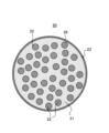
- FIG. 1 shows a schematic cross section of a negative electrode material 20 .
- the negative electrode material 20 includes a composite particle 23 (mother particle) and a coating layer 26 covering the surface of the composite particle 23.
- the composite particle 23 includes an ion-conducting phase 21 and a silicon phase (silicon particles) 22 dispersed in the ion-conducting phase 21.
- the composite particle 23 has a sea-island structure in which fine silicon phases 22 are dispersed in the matrix of the ion-conducting phase 21.
- the coating layer 26 includes a phosphate compound and a hydrophobic polymer compound.
- the negative electrode material may include other elements in addition to the composite particle and the coating layer. For example, a conductive layer may be interposed between the composite particle and the coating layer.
- the secondary battery according to the embodiment of the present disclosure includes a positive electrode, a negative electrode, and an electrolyte.
- the negative electrode contains the above-mentioned negative electrode material for secondary batteries.
- the negative electrode of the secondary battery and other components will be described below.
- the negative electrode includes a negative electrode active material capable of absorbing and releasing lithium ions.
- the negative electrode active material includes the above-mentioned negative electrode material.
- the negative electrode material includes silicon-containing particles.
- the average particle size of the silicon-containing particles is, for example, 1 ⁇ m or more and 25 ⁇ m or less. From the viewpoint of increasing capacity and improving cycle characteristics, it is preferable that the silicon-containing particles include the above-mentioned composite particles.
- the silicon-containing particles may be particles of simple silicon or silicon alloy.
- the silicon-containing alloy includes, for example, silicon (Si) and at least one element selected from the group consisting of tin (Sn), nickel (Ni), iron (Fe), copper (Cu), titanium (Ti), manganese (Mn), and aluminum (Al).
- the negative electrode active material may further contain other active material materials.
- a carbon-based active material is preferable as the other active material material. Since the composite particles expand and contract in volume with charging and discharging, if the ratio of the composite particles in the negative electrode active material increases, poor contact between the negative electrode active material and the negative electrode current collector with charging and discharging is likely to occur. On the other hand, by using the composite particles in combination with a carbon-based active material, it is possible to achieve excellent cycle characteristics while imparting the high capacity of the silicon phase to the negative electrode.
- the ratio of the composite particles to the total of the composite particles and the carbon-based active material may be, for example, 0.5 to 15 mass %, or 1 to 10 mass %. This makes it easier to achieve both high capacity and improved cycle characteristics.
- carbon-based active materials examples include graphite, easily graphitized carbon (soft carbon), and difficult-to-graphitize carbon (hard carbon). Of these, graphite is preferred because of its excellent charge/discharge stability and low irreversible capacity.
- Graphite refers to a material having a graphite-type crystal structure, and includes, for example, natural graphite, artificial graphite, and graphitized mesophase carbon particles. Carbon-based active materials may be used alone or in combination of two or more types.
- the negative electrode comprises, for example, a negative electrode current collector and a negative electrode mixture layer supported on the surface of the negative electrode current collector.
- the negative electrode mixture layer can be formed by applying a negative electrode slurry, in which the negative electrode mixture is dispersed in a dispersion medium, to the surface of the negative electrode current collector and drying it. The coating film after drying may be rolled as necessary.
- the negative electrode mixture layer may be formed on one surface or both surfaces of the negative electrode current collector.
- the negative electrode mixture contains a negative electrode active material (the negative electrode material described above) as an essential component, and can contain optional components such as a binder, a conductive agent, and a thickener.
- a non-porous conductive substrate such as metal foil
- a porous conductive substrate such as a mesh, net, or punched sheet
- the material for the negative electrode current collector include stainless steel, nickel, nickel alloy, copper, and copper alloy.
- a thickness of 1 to 50 ⁇ m is preferable, and 5 to 20 ⁇ m is more preferable.
- binders include fluororesin, polyolefin resin, polyamide resin, polyimide resin, vinyl resin, styrene-butadiene copolymer rubber (SBR), polyacrylic acid and its derivatives. These may be used alone or in combination of two or more.
- conductive agents include carbon black, conductive fibers, carbon fluoride, and organic conductive materials. These may be used alone or in combination of two or more.
- thickeners include carboxymethyl cellulose (CMC), polyvinyl alcohol, and the like. These may be used alone or in combination of two or more.
- dispersion media examples include water, alcohol, ether, N-methyl-2-pyrrolidone (NMP), and mixtures of these.
- the positive electrode includes a positive electrode active material capable of absorbing and releasing lithium ions.
- a lithium transition metal composite oxide can be used as the positive electrode active material.
- the lithium transition metal composite oxide include LiaCoO2 , LiaNiO2 , LiaMnO2 , LiaCobNi1 - bO2 , LiaCobM1- bOc , LiaNi1-bMbOc , LiaMn2O4, LiaMn2 - bMbO4 , LiMePO4 , and Li2MePO4F .
- M is at least one selected from the group consisting of Na , Mg , Sc , Y, Mn, Fe, Co, Ni, Cu, Zn, Al, Cr , Pb , Sb , and B.
- Me contains at least a transition element (e.g., contains at least one selected from the group consisting of Mn, Fe, Co, and Ni), where 0 ⁇ a ⁇ 1.2, 0 ⁇ b ⁇ 0.9, and 2.0 ⁇ c ⁇ 2.3.
- the value a which indicates the molar ratio of lithium, increases or decreases with charge and discharge.
- the positive electrode comprises, for example, a positive electrode current collector and a positive electrode mixture layer supported on the surface of the positive electrode current collector.
- the positive electrode mixture layer can be formed by applying a positive electrode slurry, in which the positive electrode mixture is dispersed in a dispersion medium, to the surface of the positive electrode current collector and drying it. The coating film after drying may be rolled as necessary.
- the positive electrode mixture layer may be formed on one surface or both surfaces of the positive electrode current collector.
- the positive electrode mixture contains a positive electrode active material as an essential component, and can contain optional components such as a binder and a conductive agent.
- binder and conductive agent the same ones as those exemplified for the negative electrode can be used.
- conductive agent graphite such as natural graphite or artificial graphite can be used.
- the shape and thickness of the positive electrode current collector can be selected from the same shape and range as the negative electrode current collector.
- Examples of materials for the positive electrode current collector include stainless steel, aluminum, aluminum alloy, and titanium.
- the electrolyte has lithium ion conductivity.
- the electrolyte may be a liquid electrolyte (electrolytic solution) or a solid electrolyte.
- the solid electrolyte for example, a solid or gel-like polymer electrolyte, an inorganic solid electrolyte, etc. can be used.
- the inorganic solid electrolyte a material known in all-solid-state lithium ion secondary batteries, etc. (for example, an oxide-based solid electrolyte, a sulfide-based solid electrolyte, a halogen-based solid electrolyte, etc.) can be used.
- the polymer electrolyte includes, for example, a lithium salt and a matrix polymer, or a non-aqueous solvent, a lithium salt, and a matrix polymer.
- the matrix polymer for example, a polymer material that absorbs a non-aqueous solvent and gels is used.
- the polymer material for example, a fluororesin, an acrylic resin, a polyether resin, etc. can be used.
- the electrolyte solution contains a solvent and an electrolyte salt.
- the solvent may be a non-aqueous solvent, or water may be used.
- the electrolyte salt contains at least a lithium salt.
- the concentration of the lithium salt in the electrolyte is preferably, for example, 0.5 mol/L or more and 2 mol/L or less. By controlling the lithium salt concentration within the above range, an electrolyte with excellent ionic conductivity and appropriate viscosity can be obtained. However, the lithium salt concentration is not limited to the above.
- non-aqueous solvents examples include cyclic carbonates, chain carbonates, and cyclic carboxylates.
- cyclic carbonates include propylene carbonate (PC) and ethylene carbonate (EC).
- chain carbonates include diethyl carbonate (DEC), ethyl methyl carbonate (EMC), and dimethyl carbonate (DMC).
- cyclic carboxylates include ⁇ -butyrolactone (GBL) and ⁇ -valerolactone (GVL).
- One type of non-aqueous solvent may be used alone, or two or more types may be used in combination.
- lithium salts of chlorine-containing acids LiClO4 , LiAlCl4 , LiB10Cl10 , etc.
- lithium salts of fluorine-containing acids LiPF6 , LiBF4 , LiSbF6 , LiAsF6 , LiCF3SO3 , LiCF3CO2 , etc.
- lithium salts of fluorine-containing acid imides LiN( CF3SO2 ) 2 , LiN( CF3SO2 )( C4F9SO2 ) , LiN( C2F5SO2 ) 2 , etc.
- lithium halides LiCl, LiBr , LiI, etc.
- the lithium salts may be used alone or in combination of two or more.
- the separator has high ion permeability and has appropriate mechanical strength and insulation properties.
- a microporous thin film, a woven fabric, a nonwoven fabric, etc. can be used.
- a polyolefin such as polypropylene or polyethylene can be used.
- a secondary battery is a structure in which an electrode group formed by winding a positive electrode and a negative electrode with a separator interposed therebetween, and an electrolyte are housed in an exterior body.
- an electrode group formed by winding a positive electrode and a negative electrode with a separator interposed therebetween, and an electrolyte are housed in an exterior body.
- other types of electrode groups may be used, such as a stacked type electrode group formed by stacking a positive electrode and a negative electrode with a separator interposed therebetween.
- the secondary battery may be in any type, such as a cylindrical type, a square type, a coin type, a button type, a laminate type, etc.
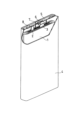
- FIG. 2 is a schematic perspective view of a secondary battery according to an embodiment of the present disclosure with a portion cut away.
- the battery comprises a rectangular battery case 4 with a bottom, and an electrode group 1 and an electrolyte (not shown) housed within the battery case 4.
- the electrode group 1 has a long strip-shaped negative electrode, a long strip-shaped positive electrode, and a separator interposed between them to prevent direct contact.
- the electrode group 1 is formed by winding the negative electrode, positive electrode, and separator around a flat winding core and removing the winding core.
- One end of the negative electrode lead 3 is attached to the negative electrode collector by welding or the like.
- the other end of the negative electrode lead 3 is electrically connected to the negative electrode terminal 6 provided on the sealing plate 5 via a resin insulating plate (not shown).
- the negative electrode terminal 6 is insulated from the sealing plate 5 by a resin gasket 7.
- One end of the positive electrode lead 2 is attached to the positive electrode collector by welding or the like.
- the other end of the positive electrode lead 2 is connected to the back surface of the sealing plate 5 via an insulating plate.
- the positive electrode lead 2 is electrically connected to the battery case 4, which also serves as the positive electrode terminal.
- the insulating plate separates the electrode group 1 from the sealing plate 5, and separates the negative electrode lead 3 from the battery case 4.
- the periphery of the sealing plate 5 fits into the open end of the battery case 4, and the fitting portion is laser welded. In this way, the opening of the battery case 4 is sealed by the sealing plate 5.
- the electrolyte injection hole provided in the sealing plate 5 is blocked by a plug 8.
- the above description of the embodiments discloses the following techniques.
- (Technique 1) A silicon-containing particle and a coating layer covering at least a part of a surface of the silicon-containing particle, The coating layer comprises a phosphate compound and a hydrophobic polymer compound.
- the silicon-containing particles include composite particles including an ion-conducting phase and a silicon phase dispersed within the ion-conducting phase.
- (Technique 3) The negative electrode material for a secondary battery according to claim 2, wherein the ion conductive phase includes at least one selected from the group consisting of a silicate phase, a silicon oxide phase, and a carbon phase.
- the organic group is represented by the above formula (2).
- Technique 6 The negative electrode material for a secondary battery according to claim 4 or 5, wherein the polyphosphate compound includes at least one selected from the group consisting of tripolyphosphates and tetrapolyphosphates.
- the phosphate compound includes at least one selected from the group consisting of monosodium phosphate, disodium phosphate, trisodium phosphate, monopotassium phosphate, dipotassium phosphate, tripotassium phosphate, trilithium phosphate, monoammonium phosphate, diammonium phosphate, triammonium phosphate, monocalcium phosphate, dicalcium phosphate, tricalcium phosphate, monomagnesium phosphate, dimagnesium phosphate, trimagnesium phosphate, monoaluminum phosphate, dialuminum phosphate, trialuminum phosphate, manganese biphosphate, zinc phosphate, and boron phosphate.
- the amount of the phosphate compound attached to the surface of the silicon-containing particle is 1 part by mass or more per 100 parts by mass of the silicon-containing particle.
- the fluororesin includes at least one selected from the group consisting of polyvinylidene fluoride, polytetrafluoroethylene, tetrafluoroethylene-perfluoroalkyl vinyl ether copolymer, tetrafluoroethylene-hexafluoropropylene copolymer, tetrafluoroethylene-ethylene copolymer, chlorotrifluoroethylene-ethylene copolymer, and polychlorotrifluoroethylene.
- the negative electrode material for secondary batteries according to any one of claims 1 to 12, wherein the amount of the hydrophobic polymer compound attached to the surface of the silicon-containing particle is 1 part by mass or more per 100 parts by mass of the silicon-containing particle.
- the negative electrode comprises the negative electrode material for secondary batteries according to any one of techniques 1 to 16.
- ⁇ Secondary batteries A1 to A3> (Preparation of Composite Particles) A mixture was obtained by mixing lithium carbonate ( Li2CO3 ) as a Li raw material and silicon dioxide ( SiO2 ) as a Si raw material so that the atomic ratio: Si/Li was 1.05. The mixture was fired at 800°C for 10 hours in an inert gas atmosphere to obtain lithium silicate (Li2Si2O5 ) . The obtained lithium silicate was pulverized to an average particle size of 10 ⁇ m .
- the crushed lithium silicate and raw silicon (3N, average particle size 10 ⁇ m) were mixed in a mass ratio of 40:60.
- the mixture was loaded into a pot (SUS, volume: 500 mL) of a planetary ball mill (Fritsch, P-5). Next, 24 SUS balls (diameter 20 mm) were placed in the pot, the lid was closed, and the mixture was milled at 200 rpm for 50 hours in an inert atmosphere.
- the powder mixture was then removed from the inert atmosphere and sintered at 600°C for 4 hours in an inert atmosphere while applying pressure from a hot press machine, to obtain a sintered body of the mixture.
- the obtained sintered body of the mixture was pulverized and passed through a 40 ⁇ m mesh to obtain composite particles (silicate phase-containing composite particles). After that, a sieve was used to obtain composite particles with an average particle size of 10 ⁇ m.
- the crystallite size of the silicon phase was 15 nm.
- the silicon phase was particulate, and the average particle size of the silicon phase was 20 nm.
- the main component of the silicate phase was Li 2 Si 2 O 5 , and the content of the silicon phase in the silicate phase-containing composite particles was 60 mass%.
- PVDF powder was added to the first intermediate and dry mixed to obtain a second intermediate (composite particles with a phosphate compound and PVDF attached to the surface).
- the amount of PVDF added was the value shown in Table 1 relative to 100 parts by mass of the composite particles. Dry mixing was performed using a ball mill at room temperature (25°C) for 30 minutes. For the ball milling, a "rocking mill” manufactured by Seiwa Giken Co., Ltd. was used, and zirconia balls (diameter 3 mm) were used.
- the second intermediate was subjected to a heat treatment at 250° C. for 2 hours in an inert atmosphere.
- the heat treatment liquefied the PVDF attached to the surface of the composite particle, thereby enhancing the retention of the phosphate compound on the surface of the composite particle.
- a coating layer containing the phosphate compound and PVDF was formed on the surface of the composite particle having a conductive layer, and a negative electrode material was obtained.
- TOF-SIMS analysis detected ions derived from disodium etidronate on the surface of the negative electrode material.
- XPS analysis confirmed that PVDF was more abundant in the surface layer of the coating layer than in the inner layer of the coating layer.
- Graphite and composite particles having a conductive layer and a coating layer were mixed in a mass ratio of 90:10 and used as the negative electrode active material.
- 1 part by mass of carboxymethyl cellulose (CMC) and 1.5 parts by mass of styrene butadiene rubber (SBR) were added to 97.5 parts by mass of the negative electrode active material, and a predetermined amount of water was further added to prepare a negative electrode slurry.
- the negative electrode slurry was applied to both sides of the copper foil negative electrode current collector, the coating was dried, rolled, and then cut to a specified size to obtain a negative electrode with a negative electrode mixture layer formed on both sides of the negative electrode current collector. At this time, a negative electrode current collector exposed portion was provided on part of the negative electrode.
- a positive electrode slurry was prepared by adding 2.5 parts by mass of acetylene black and 2.5 parts by mass of polyvinylidene fluoride to 95 parts by mass of the positive electrode active material, and further adding an appropriate amount of N-methyl- 2 -pyrrolidone ( NMP ).
- the positive electrode active material used was a lithium transition metal composite oxide represented by LiNi0.88Co0.09Al0.03O2 .
- the positive electrode slurry was applied to both sides of the aluminum foil positive electrode current collector, the coating was dried, rolled, and then cut to a specified size to obtain a positive electrode with a positive electrode mixture layer formed on both sides of the positive electrode current collector. At this time, a positive electrode current collector exposed portion was provided on part of the positive electrode.
- Ethylene carbonate (EC), ethyl methyl carbonate (EMC), and dimethyl carbonate (DMC) were mixed in a volume ratio of 20:5:75 to obtain a mixed solvent.
- Lithium hexafluorophosphate was dissolved in the mixed solvent at a concentration of 1 mol/L to prepare an electrolyte solution.
- a secondary battery B1 was obtained in the same manner as the secondary battery A1, except that no coating layer was formed on the surface of the composite particle having a conductive layer.
- Secondary batteries B2 to B4 were obtained in the same manner as secondary batteries A1 to A3, except that the second and third steps were not performed and PVDF was not added.
- a secondary battery B5 was obtained in the same manner as the secondary battery A1, except that the first step was not carried out and no phosphate compound was added.
- the discharge capacity retention rate R (%) was calculated using the following formula using the discharge capacity C1 at the first cycle and the discharge capacity C2 at the 300th cycle.
- Discharge capacity retention rate R (discharge capacity C2/discharge capacity C1) x 100
- the cycle deterioration rate after 300 cycles was calculated using the obtained discharge capacity retention rate R according to the following formula. Note that R0 in the formula is the discharge capacity retention rate R of secondary battery B1.
- Cycle deterioration rate ⁇ (100-R)/(100-R0) ⁇ x 100
- the batteries A1 to A3 exhibited smaller cycle deterioration rates and better cycle characteristics than the batteries B1 to B5.
- the cycle deterioration rate was significantly smaller when a phosphate compound was added than when no phosphate compound was added by adding PVDF (B1 ⁇ B5, B2 ⁇ A1, B3 ⁇ A2, B4 ⁇ A3).
- the carbon source, coal pitch (MCP250, manufactured by JFE Chemical Corporation), and raw silicon (3N, average particle size 10 ⁇ m) were mixed in a mass ratio of 50:50.
- the mixture was loaded into a pot (SUS, volume: 500 mL) of a planetary ball mill (P-5, manufactured by Fritsch), 24 SUS balls (diameter 20 mm) were placed in the pot, the lid was closed, and the mixture was milled in an inert atmosphere at 200 rpm for 50 hours to obtain a composite of the silicon phase and the carbon source.
- the composite of the silicon phase and the carbon source was sintered in an inert gas atmosphere to carbonize the carbon source and obtain a sintered product in which the silicon phase was dispersed within the carbon phase containing amorphous carbon.
- the sintered product was then pulverized using a jet mill to obtain composite particles containing the carbon phase with an average particle size of 10 ⁇ m.
- the crystallite size of the silicon phase was 15 nm.
- the silicon phase was particulate, and the average particle size of the silicon phase was 20 nm.
- the content of the silicon phase in the carbon phase-containing composite particles was 60 mass%.
- Secondary batteries C1 to C3 were obtained in the same manner as secondary batteries A1 to A3, except that in the negative electrode material production process, carbon phase-containing composite particles were used instead of silicate phase-containing composite particles with a conductive layer.
- Secondary batteries D1 to D5 were obtained in the same manner as secondary batteries B1 to B5, except for the above.
- the secondary batteries C1 to C3 and D1 to D5 obtained above were evaluated in the same manner as above, and the cycle deterioration rate at 350 cycles was determined.
- C2 in the calculation formula for the discharge capacity retention rate R was taken as the discharge capacity at the 350th cycle.
- R0 in the calculation formula for the cycle deterioration rate was taken as the discharge capacity retention rate R of the secondary battery D1.
- C1 to C3 are batteries of the embodiment
- D1 to D5 are batteries of the comparative example.
- the batteries C1 to C3 exhibited a smaller cycle deterioration rate and superior cycle characteristics than the batteries D1 to D5.
- the cycle deterioration rate was significantly smaller when a phosphate compound was added than when no phosphate compound was added by adding PVDF (D1 ⁇ D5, D2 ⁇ C1, D3 ⁇ C2, D4 ⁇ C3).
- Si single particles (average particle size 10 ⁇ m) were used instead of composite particles. No conductive layer was formed on the surface of the Si single particles.
- secondary battery E1 was obtained in the same manner as secondary battery A2.
- secondary batteries F1 to F2 were obtained in the same manner as secondary batteries B1, B3, and B5, respectively.
- the secondary batteries E1, F1 to F3 obtained above were evaluated in the same manner as above to determine the cycle deterioration rate after 100 cycles.
- C2 in the calculation formula for the discharge capacity retention rate R was taken as the discharge capacity at the 100th cycle.
- R0 in the calculation formula for the cycle deterioration rate was taken as the discharge capacity retention rate R of the secondary battery F1.
- the cycle deterioration rate was smaller and superior cycle characteristics were obtained as compared with the batteries F1 to F3.
- the cycle deterioration rate was significantly smaller when a phosphate compound was added than when no phosphate compound was added by adding PVDF (F1 ⁇ F3, F2 ⁇ E1).
- the secondary battery disclosed herein is useful as a main power source for mobile communication devices, portable electronic devices, etc.
Landscapes
- Chemical & Material Sciences (AREA)
- Chemical Kinetics & Catalysis (AREA)
- Electrochemistry (AREA)
- General Chemical & Material Sciences (AREA)
- Composite Materials (AREA)
- Engineering & Computer Science (AREA)
- Materials Engineering (AREA)
- Battery Electrode And Active Subsutance (AREA)
Abstract
Description
本開示の一実施形態に係る二次電池用負極材料は、ケイ素含有粒子(Si系活物質)と、ケイ素含有粒子の表面の少なくとも一部を覆う被覆層と、を備える。被覆層は、リン酸塩化合物と、疎水性ポリマー化合物と、を含む。
リン酸塩化合物を含む被覆層は、低抵抗であり、良好なイオン伝導性を有する。リン酸塩化合物は、P(=O)O-の構造(「PO構造」とも称する。)を有するアニオンと、カチオンと、を形成し得る。カチオンは、金属イオン、アンモニウムイオン(NH4 +)等を含む。
一般式(1)中のAが有機基であり、有機基は、式(2):
疎水性ポリマー化合物は、良好な結着性および熱溶融性を有することが望ましい。この場合、疎水性ポリマー化合物によりケイ素含有粒子の表面にリン酸塩化合物を強固に担持させることができ、リン酸塩化合物による副反応の抑制効果が安定して得られ易い。疎水性ポリマー化合物は、水に殆ど溶けない。
負極材料が、導電層を有するケイ素化合物相含有複合粒子を備える場合、水およびNMPに溶解しない残りについて炭素硫黄分析装置等を用いて炭素の定量分析を行う。求められる炭素量は、導電層の炭素材料に由来する。水およびNMPに溶解しない残りの質量から分析より求められた炭素の質量を差し引いた値を、ケイ素化合物相含有複合粒子の質量として求める。
上記で求められたリン酸塩化合物の質量およびケイ素含有粒子の質量を用いて、(リン酸塩化合物の質量/ケイ素含有粒子の質量)×100によりリン酸塩化合物の担持量を求める。
ケイ素含有粒子が複合粒子である場合、イオン伝導相の成分によっては導電性が比較的低い場合がある。導電性の向上の観点から、複合粒子と被覆層との間に導電性炭素材料を含む導電層が介在していてもよい。すなわち、被覆層は、複合粒子表面の導電層を覆うように形成されていてもよい。導電層の厚さは、実質上、複合粒子の平均粒径に影響しない程度に薄いことが好ましい。導電性の確保の観点から、導電層の厚さは1nm以上が好ましい。抵抗の増大抑制の観点から、被覆層および導電層を合計した厚さは300nm以下が好ましい。導電層の厚さは、被覆層の場合と同様にして計測できる。
二次電池用負極材料の作製方法(被覆層の形成方法)は、例えば、以下の第1工程~第3工程を含む。
第1工程:リン酸塩化合物とケイ酸含有粒子とを湿式混合し、乾燥する。このようにして、第1中間体(表面にリン酸塩化合物が付着したケイ素含有粒子)を得る。
第2工程:第1中間体と疎水性ポリマー化合物とを乾式混合する。このようにして、第2中間体(表面にリン酸塩化合物および疎水性ポリマー化合物が付着したケイ素含有粒子)を得る。
第3工程:不活性雰囲気中で第2中間体を熱処理する。このようにして、ケイ素含有粒子の表面にリン酸塩化合物および疎水性ポリマー化合物を含む被覆層を形成する。
第1工程および第2工程は、大気中で行ってもよいが、不活性雰囲気中で行うことが好ましい。
第1工程の湿式混合では、リン酸塩化合物と溶媒(分散媒)とを混合し、その後、リン酸塩化合物の溶液(分散液)とケイ素含有粒子とを混合してもよい。
溶媒(分散媒)には、水、アルコール等を用いることができ、中でも水が好ましい。この場合、ケイ素含有粒子の表面をリン酸塩化合物で均一に被覆し易い。
乾式混合は、ボールミルを用いて行うことができる。第2工程での疎水性ポリマー化合物の添加量は、ケイ素含有粒子100質量部に対して、1質量部以上(もしくは2質量部以上)、6質量部以下であってもよい。
熱処理工程では、第2中間体は、例えば、疎水性ポリマー化合物の融点以上の温度に加熱される。熱処理工程により、疎水性ポリマー化合物が液状化し、ケイ素含有粒子とリン酸塩化合物の粒子との隙間、およびリン酸塩化合物の粒子同士の隙間を埋めるようにケイ素含有粒子およびリン酸塩化合物の粒子の周囲に浸透し、拡散する。これにより、ケイ素含有粒子表面でのリン酸塩化合物の保持性が大幅に高められる。第2中間体を熱処理したものを解砕することにより被覆層を有するケイ素含有粒子が得られる。ケイ素含有粒子が、表面に導電層を有する複合粒子である場合、導電層を介してケイ素含有粒子の表面に被覆層が形成されてもよい。
非水溶性ポリマー化合物は、例えば、25℃の水100gにポリマー化合物1gを投入して水を十分に撹拌したときに溶解するポリマ化合物が0.02g未満(もしくは0.01g以下)である。
非水溶性ポリマー化合物としては、疎水性ポリマー化合物(例えばフッ素樹脂)の他、ポリメチルメタクリレート、ポリエチレンテレフタレート、ポリブチレンテレフタレート、ポリアクリロニトリル、ポリイミド、ポリアミド、ポリエチレン、ポリプロピレン、ポリスチレン、ポリ塩化ビニル、ポリカーボネート等が挙げられる。
ケイ素含有粒子が複合粒子である場合、複合粒子(イオン伝導相)の表面がリン酸塩化合物および疎水性ポリマー化合物で被覆されることにより、複合粒子が電解質から保護され、電解質との副反応が抑制され、副反応に伴うイオン伝導相の浸食が抑制される。当該浸食に起因する複合粒子の劣化によるサイクル特性の低下が抑制される。
負極合剤層の反射電子像の断面画像から、粒子の最大径が5μm以上の複合粒子を無作為に10個選び出して、それぞれについてエネルギー分散型X線(EDX)による元素のマッピング分析を行う。画像解析ソフトを用いて対象となる元素の面積割合を算出する。観察倍率は2000~20000倍が望ましい。粒子10個に含まれる所定の元素の面積割合の測定値を平均する。得られた平均値から対象となる元素の含有量が算出される。
<SEM-EDX測定条件>
加工装置:JEOL製、SM-09010(Cross Section Polisher)
加工条件:加速電圧6kV
電流値:140μA
真空度:1×10⁻³~2×10⁻³Pa
測定装置:電子顕微鏡HITACHI製SU-70
分析時加速電圧:10kV
フィールド:フリーモード
プローブ電流モード:Medium
プローブ電流範囲:High
アノード Ap.:3
OBJ Ap.:2
分析エリア:1μm四方
分析ソフト:EDAX Genesis
CPS:20500
Lsec:50
時定数:3.2
負極合剤層の反射電子像の断面画像から、粒子の最大径が5μm以上の複合粒子を無作為に10個選び出して、それぞれについてオージェ電子分光(AES)分析装置(例えば日本電子社製、JAMP-9510F)を用いて元素の定性定量分析を行う。測定条件は、例えば、加速電圧10kV、ビーム電流10nA、分析領域20μmφとすればよい。粒子10個に含まれる所定の元素の含有量を平均して含有量が算出される。
複合粒子の試料を、加熱した酸溶液(フッ化水素酸、硝酸および硫酸の混酸)中で全溶解し、溶液残渣の炭素を濾過して除去する。その後、得られた濾液を誘導結合プラズマ発光分光分析法(ICP)で分析して、各元素のスペクトル強度を測定する。続いて、市販されている元素の標準溶液を用いて検量線を作成し、複合粒子に含まれる各元素の含有量を算出する。
<Si-NMR測定条件>
測定装置:バリアン社製、固体核磁気共鳴スペクトル測定装置(INOVA‐400)
プローブ:Varian 7mm CPMAS-2
MAS:4.2kHz
MAS速度:4kHz
パルス:DD(45°パルス+シグナル取込時間1Hデカップル)
繰り返し時間:1200sec~3000sec
観測幅:100kHz
観測中心:-100ppm付近
シグナル取込時間:0.05sec
積算回数:560
試料量:207.6mg
リチウムシリケートの原料には、Siを含む原料と、Li原料とを所定の割合で含む原料混合物を用いる。原料混合物に、必要に応じて他の元素Mを含ませてもよい。上記原料を所定量混合した混合物を溶解し、融液を金属ロールに通してフレーク化してリチウムシリケートを作製する。その後フレーク化したシリケートを大気雰囲気で、ガラス転移点以上、融点以下の温度で熱処理により結晶化させる。なお、フレーク化したシリケートは結晶化させずに使用することも可能である。また所定量混合した混合物を溶解せずに、融点以下の温度で焼成して固相反応によりシリケートを製造することも可能である。
リチウムシリケート内には、Li原料と反応しなかったSi原料が残存し得る。残存するSi原料は、酸化シリコンの微細結晶として、リチウムシリケート内に分散している。
次に、リチウムシリケートに原料シリコンを配合して複合化が行われる。例えば、以下の工程(a)~(c)を経て、複合粒子が作製される。
まず、原料シリコンの粉末とリチウムシリケートの粉末とを、例えば、20:80~95:5の質量比で混合する。原料シリコンには、平均粒径が数μm~数十μm程度のシリコンの粗粒子を用いればよい。
次に、ボールミルのような粉砕装置を用いて、原料シリコンとリチウムシリケートの混合物を微粒子化しながら粉砕および複合化する。このとき、混合物に有機溶媒を添加して、湿式粉砕してもよい。所定量の有機溶媒を粉砕初期に一度に粉砕容器に投入してもよく、粉砕過程で所定量の有機溶媒を複数回に分けて間欠的に粉砕容器に投入してもよい。有機溶媒は、粉砕対象物の粉砕容器の内壁への付着を防ぐ役割を果たす。
次に、粉砕物を、ホットプレス等で圧力を印加しながら焼成して焼結体を得る。焼成は、例えば、不活性雰囲気(例えば、アルゴン、窒素等の雰囲気)中で行われる。焼成温度は、450℃以上、1000℃以下であることが好ましい。上記温度範囲である場合、結晶性が低いシリケート相内に微小なシリコン粒子を分散させやすい。焼結時に、リチウムシリケートが軟化し、シリコン粒子間の隙間を埋めるように流動する。その結果、シリケート相を海部とし、シリコン粒子を島部とする緻密なブロック状の焼結体を得ることができる。焼成温度は、好ましくは550℃以上、900℃以下であり、より好ましくは650℃以上、850℃以下である。焼成時間は、例えば、1時間以上、10時間以下である。
工程(i)および工程(ii)により、シリケート相をマトリクスとし、マトリクス中に分散しているシリコン相を有する複合粒子が得られる。
負極材料20は、複合粒子23(母粒子)と、複合粒子23の表面を覆う被覆層26と、を備える。複合粒子23は、イオン伝導相21と、イオン伝導相21内に分散しているシリコン相(シリコン粒子)22と、を備える。複合粒子23は、イオン伝導相21のマトリックス中に微細なシリコン相22が分散した海島構造を有する。被覆層26は、リン酸塩化合物および疎水性ポリマー化合物を含む。負極材料は、複合粒子および被覆層以外に、他の要素を含んでもよい。例えば、複合粒子と被覆層との間に導電層が介在していてもよい。
本開示の実施形態に係る二次電池は、正極と、負極と、電解質と、を備える。負極は、上記の二次電池用負極材料を含む。以下、二次電池の負極などについて説明する。
負極は、リチウムイオンの吸蔵および放出が可能な負極活物質を含む。負極活物質は、上記の負極材料を含む。負極材料は、ケイ素含有粒子を含む。ケイ素含有粒子の平均粒径は、例えば、1μm以上、25μm以下である。高容量化およびサイクル特性の向上の観点から、ケイ素含有粒子は、上記の複合粒子を含むことが好ましい。ケイ素含有粒子は、ケイ素単体またはケイ素合金の粒子であってもよい。ケイ素を含む合金は、例えば、ケイ素(Si)と、スズ(Sn)、ニッケル(Ni)、鉄(Fe)、銅(Cu)、チタン(Ti)、マンガン(Mn)、およびアルミニウム(Al)からなる群より選択される少なくとも1種の元素と、を含む。
正極は、リチウムイオンの吸蔵および放出が可能な正極活物質を含む。正極活物質には、例えば、リチウム遷移金属複合酸化物を用いることができる。リチウム遷移金属複合酸化物としては、例えば、LiaCoO2、LiaNiO2、LiaMnO2、LiaCobNi1-bO2、LiaCobM1-bOc、LiaNi1-bMbOc、LiaMn2O4、LiaMn2-bMbO4、LiMePO4、Li2MePO4Fが挙げられる。ここで、Mは、Na、Mg、Sc、Y、Mn、Fe、Co、Ni、Cu、Zn、Al、Cr、Pb、Sb、およびBよりなる群から選択される少なくとも1種である。Meは、少なくとも遷移元素を含む(例えば、Mn、Fe、Co、Niよりなる群から選択される少なくとも1種を含む)。ここで、0≦a≦1.2、0≦b≦0.9、2.0≦c≦2.3である。なお、リチウムのモル比を示すa値は、充放電により増減する。
電解質は、リチウムイオン伝導性を有する。電解質は、液状の電解質(電解液)であってもよく、固体電解質であってもよい。
通常、正極と負極との間には、セパレータを介在させることが望ましい。セパレータは、イオン透過度が高く、適度な機械的強度および絶縁性を備えている。セパレータとしては、微多孔薄膜、織布、不織布などを用いることができる。セパレータの材質としては、例えば、ポリプロピレン、ポリエチレンなどのポリオレフィンが用いられ得る。
以上の実施形態の記載により、以下の技術が開示される。
(技術1)
ケイ素含有粒子と、前記ケイ素含有粒子の表面の少なくとも一部を覆う被覆層と、を備え、
前記被覆層は、リン酸塩化合物と、疎水性ポリマー化合物と、を含む、二次電池用負極材料。
(技術2)
前記ケイ素含有粒子は、イオン伝導相と、前記イオン伝導相内に分散しているシリコン相と、を含む複合粒子を含む、技術1に記載の二次電池用負極材料。
(技術3)
前記イオン伝導相は、シリケート相、酸化シリコン相、および炭素相からなる群より選択される少なくとも1種を含む、技術2に記載の二次電池用負極材料。
(技術4)
前記リン酸塩化合物は、上記の一般式(1)で表されるアニオンを含むリン酸塩化合物、ポリリン酸塩化合物、およびメタリン酸塩化合物からなる群より選択される少なくとも1種のリン酸塩化合物を含み、一般式(1)中、Aは有機基または酸素原子である、技術1~3のいずれか1つに記載の二次電池用負極材料。
(技術5)
前記有機基は、上記の式(2)で表される、技術4に記載の二次電池用負極材料。
(技術6)
前記ポリリン酸塩化合物は、トリポリリン酸塩およびテトラポリリン酸塩からなる群より選択される少なくとも1種を含む、技術4または5に記載の二次電池用負極材料。
(技術7)
前記メタリン酸塩化合物は、トリメタリン酸塩およびヘキサメタリン酸塩からなる群より選択される少なくとも1種を含む、技術4~6のいずれか1つに記載の二次電池用負極材料。
(技術8)
前記リン酸塩化合物は、トリポリリン酸ナトリウム、テトラポリリン酸ナトリウム、トリメタリン酸ナトリウム、ヘキサメタリン酸ナトリウム、トリメタリン酸カリウム、ヘキサメタリン酸カリウム、エチドロン酸二ナトリウム、エチドロン酸四ナトリウム、ピロリン酸ナトリウム、ピロリン酸カリウム、ピロリン酸カルシウム、およびピロリン酸第二鉄からなる群より選択される少なくとも1種を含む、技術4~7のいずれか1つに記載の二次電池用負極材料。
(技術9)
前記リン酸塩化合物は、リン酸一ナトリウム、リン酸二ナトリウム、リン酸三ナトリウム、リン酸一カリウム、リン酸二カリウム、リン酸三カリウム、リン酸三リチウム、リン酸一アンモニウム、リン酸二アンモニウム、リン酸三アンモニウム、第一リン酸カルシウム、第二リン酸カルシウム、第三リン酸カルシウム、第一リン酸マグネシウム、第二リン酸マグネシウム、第三リン酸マグネシウム、第一リン酸アルミニウム、第二リン酸アルミニウム、第三リン酸アルミニウム、重リン酸マンガン、リン酸亜鉛、およびリン酸ホウ素からなる群より選択される少なくとも1種を含む、技術1~3のいずれか1つに記載の二次電池用負極材料。
(技術10)
前記ケイ素含有粒子の表面に付着している前記リン酸塩化合物の量は、前記ケイ素含有粒子の100質量部に対して、1質量部以上である、技術1~9のいずれか1つに記載の二次電池用負極材料。
(技術11)
前記疎水性ポリマー化合物は、フッ素樹脂を含む、技術1~10のいずれか1つに記載の二次電池用負極材料。
(技術12)
前記フッ素樹脂は、ポリフッ化ビニリデン、ポリテトラフルオロエチレン、テトラフルオロエチレン-パーフルオロアルキルビニルエーテル共重合体、テトラフルオロエチレン-ヘキサフルオロプロピレン共重合体、テトラフルオロエチレン-エチレン共重合体、クロロトリフルオロエチレン-エチレン共重合体、およびポリクロロトリフルオロエチレンからなる群より選択される少なくとも1種を含む、技術11に記載の二次電池用負極材料。
(技術13)
前記ケイ素含有粒子の表面に付着している前記疎水性ポリマー化合物の量は、前記ケイ素含有粒子の100質量部に対して、1質量部以上である、技術1~12のいずれか1つに記載の二次電池用負極材料。
(技術14)
飛行時間型二次イオン質量分析により、前記被覆層において、前記リン酸塩化合物に由来するイオンが検出される、技術1~13のいずれか1つに記載の二次電池用負極材料。
(技術15)
前記複合粒子と前記被覆層との間に、導電性炭素材料を含む導電層が介在している、技術2または3に記載の二次電池用負極材料。
(技術16)
ケイ素含有粒子と、前記ケイ素含有粒子の表面の少なくとも一部を覆う被覆層と、を備え、
前記被覆層は、リン酸塩化合物と、非水溶性ポリマー化合物と、を含む、二次電池用負極材料。
(技術17)
正極と、負極と、電解質と、を備え、
前記負極は、技術1~16のいずれか1つに記載の二次電池用負極材料を含む、二次電池。
以下、本開示の実施例について具体的に説明するが、本開示は以下の実施例に限定されない。
(複合粒子の調製)
Li原料として炭酸リチウム(Li2CO3)と、Si原料として二酸化ケイ素(SiO2)とを、原子比:Si/Liが1.05の比率となるように混合し、混合物を得た。混合物を不活性ガス雰囲気中で800℃で10時間焼成し、リチウムシリケート(Li2Si2O5)を得た。得られたリチウムシリケートは平均粒径10μmになるように粉砕した。
その後、複合粒子100質量部をコールタールピッチ3質量部とを混合し、混合物を不活性雰囲気で、800℃で焼成し、複合粒子の表面を導電性炭素で被覆した。このようにして、複合粒子の表面に導電層を形成した。導電層の被覆量は、複合粒子と導電層との合計に対して3質量%とした。
(第1工程)
リン酸塩化合物に純水を加えて30分間撹拌し、その後、導電層を有する複合粒子を更に加えて30分間撹拌した。その後、乾燥を80℃で12時間行い、水を除去した。このようにして、第1中間体(表面にリン酸塩化合物が付着した複合粒子)を得た。撹拌装置には、ホモミキサー(プライミクス社製)を用いた。リン酸塩化合物の添加量は、複合粒子100質量部に対して、表1に示す値とした。リン酸塩化合物には、エチドロン酸二ナトリウムを用いた。
第1中間体にPVDFの粉末を加えて乾式混合し、第2中間体(表面にリン酸塩化合物およびPVDFが付着した複合粒子)を得た。PVDFの添加量は、複合粒子100質量部に対して、表1に示す値とした。乾式混合はボールミルにより行い、常温(25℃)で30分間行った。ボールミル処理にはセイワ技研社製の「ロッキングミル」を用い、ジルコニアボール(直径3mm)を用いた。
第2中間体について不活性雰囲気中で250℃で熱処理を2時間行った。当該熱処理により、複合粒子の表面に付着しているPVDFを液状化させて、複合粒子表面でのリン酸塩化合物の保持性を高めた。このようにして、導電層を有する複合粒子の表面に、リン酸塩化合物およびPVDFを含む被覆層を形成し、負極材料を得た。
黒鉛と、導電層および被覆層を有する複合粒子(負極材料)とを、90:10の質量比で混合し、これを負極活物質として用いた。負極活物質97.5質量部に、カルボキシメチルセルロース(CMC)1質量部と、スチレンブタジエンゴム(SBR)1.5質量部とを加え、さらに所定量の水を加えて、負極スラリーを調製した。
正極活物質95質量部に、アセチレンブラック2.5質量部と、ポリフッ化ビニリデン2.5質量部とを加え、さらに適量のN-メチル-2-ピロリドン(NMP)を加えて、正極スラリーを調製した。正極活物質には、LiNi0.88Co0.09Al0.03O2で表されるリチウム遷移金属複合酸化物を用いた。
エチレンカーボネート(EC)と、エチルメチルカーボネート(EMC)と、ジメチルカーボネート(DMC)とを、20:5:75の体積比で混合し、混合溶媒を得た。混合溶媒に六フッ化リン酸リチウムを1モル/リットルの濃度で溶解させ、電解液を調製した。
正極の正極集電体露出部にアルミニウム製の正極リードを取り付け、負極の負極集電体露出部にニッケル製の負極リードを取り付けた。ポリオレフィン製のセパレータを介して正極と負極とを渦巻き状に巻回した後、径方向にプレスし、扁平状の巻回型電極体を作製した。この電極体をアルミラミネートシートで構成される外装体内に収容し、電解液を注入した後、外装体の開口部を封止した。このようにして、評価用の二次電池A1~A3を得た。
導電層を有する複合粒子の表面に被覆層を形成しなかった以外、二次電池A1と同様にして、二次電池B1を得た。
第2工程および第3工程を行わず、PVDFを添加しなかった以外、二次電池A1~A3と同様にして、二次電池B2~B4を得た。
第1工程を行わず、リン酸塩化合物を添加しなかった以外、二次電池A1と同様にして、二次電池B5を得た。
上記で得られた二次電池A1~A3、B1~B5について、以下の評価を行った。
25℃の環境下、電圧が4.2Vになるまで0.3Cの電流で定電流充電を行った後、電流が0.02Cになるまで4.2Vの電圧で定電圧充電を行った。その後、電圧が2.5Vになるまで0.5Cの電流で放電した。この充放電を1サイクルとして、300サイクル行った。
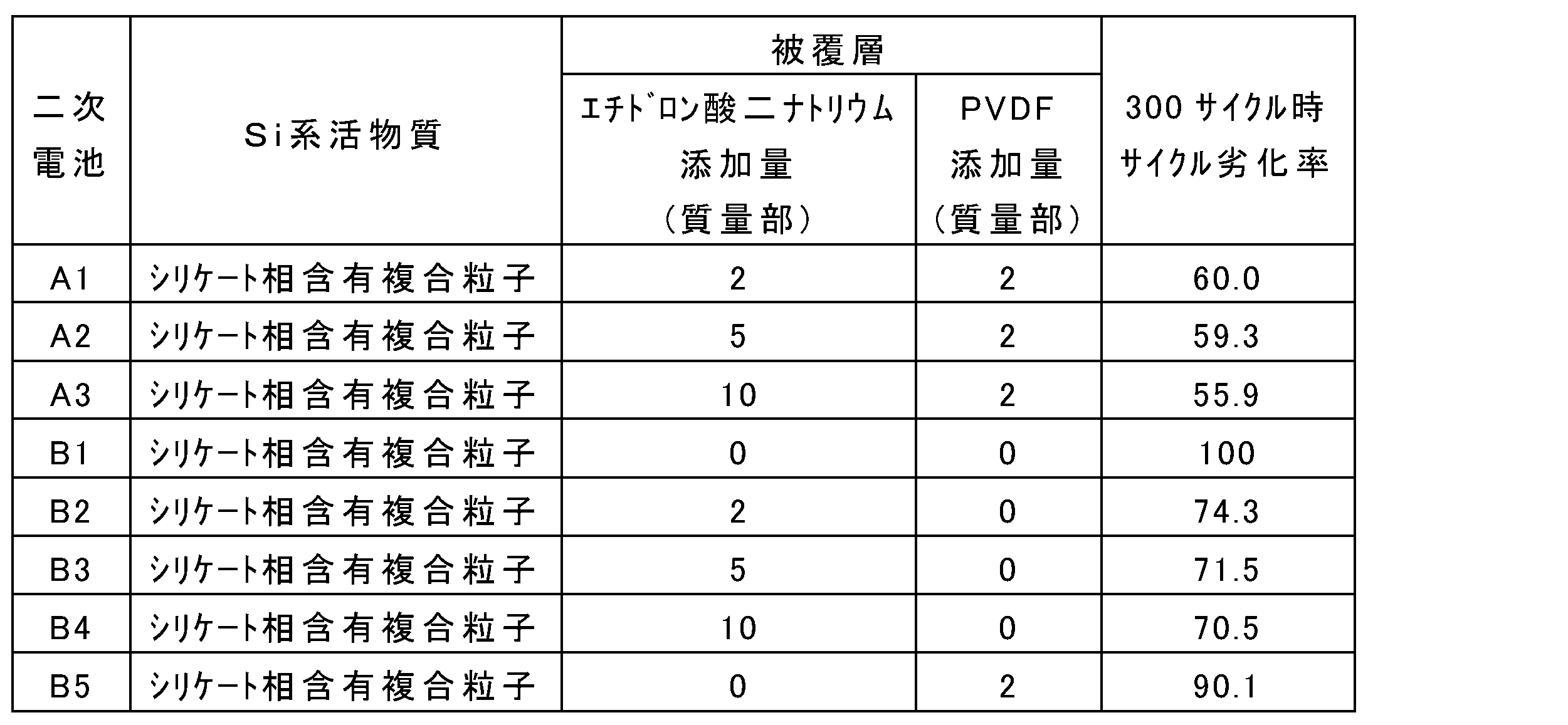
リン酸塩化合物が無添加の場合よりもリン酸塩化合物を添加する場合の方が、PVDFの添加によりサイクル劣化率が大幅に小さくなった(B1→B5、B2→A1、B3→A2、B4→A3)。
複合粒子には炭素相含有複合粒子を用いた。炭素相含有複合粒子は、以下のようにして作製した。
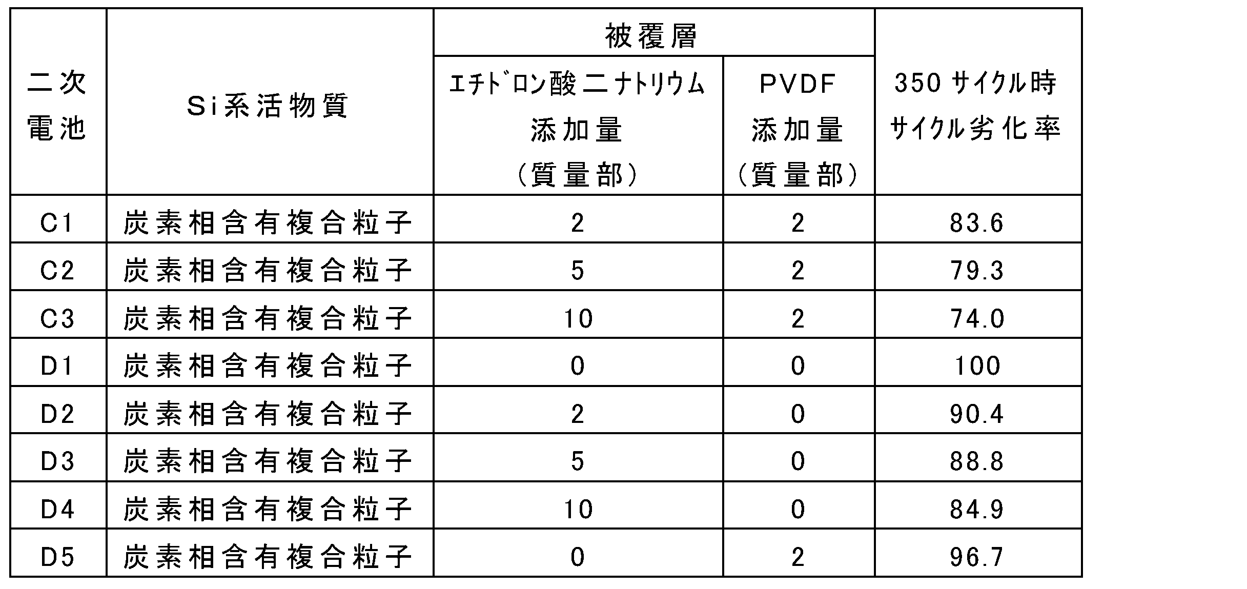
リン酸塩化合物が無添加の場合よりもリン酸塩化合物を添加する場合の方が、PVDFの添加によりサイクル劣化率が大幅に小さくなった(D1→D5、D2→C1、D3→C2、D4→C3)。
ケイ素含有粒子として複合粒子の代わりにSi単体粒子(平均粒径10μm)を用いた。Si単体粒子の表面には導電層を形成しなかった。負極材料の作製工程において、導電層を有するシリケート相含有複合粒子の代わりにSi単体粒子を用いた以外、二次電池A2と同様にして二次電池E1を得た。また、上記以外、二次電池B1、B3、B5と同様にして、それぞれ二次電池F1~F2を得た。
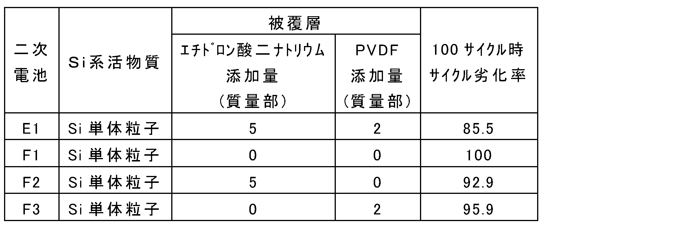
リン酸塩化合物が無添加の場合よりもリン酸塩化合物を添加する場合の方が、PVDFの添加によりサイクル劣化率が大幅に小さくなった(F1→F3、F2→E1)。
Claims (17)
- ケイ素含有粒子と、前記ケイ素含有粒子の表面の少なくとも一部を覆う被覆層と、を備え、
前記被覆層は、リン酸塩化合物と、疎水性ポリマー化合物と、を含む、二次電池用負極材料。 - 前記ケイ素含有粒子は、イオン伝導相と、前記イオン伝導相内に分散しているシリコン相と、を含む複合粒子を含む、請求項1に記載の二次電池用負極材料。
- 前記イオン伝導相は、シリケート相、酸化シリコン相、および炭素相からなる群より選択される少なくとも1種を含む、請求項2に記載の二次電池用負極材料。
- 前記リン酸塩化合物は、一般式(1):

- 前記有機基は、式(2):

- 前記ポリリン酸塩化合物は、トリポリリン酸塩およびテトラポリリン酸塩からなる群より選択される少なくとも1種を含む、請求項4に記載の二次電池用負極材料。
- 前記メタリン酸塩化合物は、トリメタリン酸塩およびヘキサメタリン酸塩からなる群より選択される少なくとも1種を含む、請求項4に記載の二次電池用負極材料。
- 前記リン酸塩化合物は、トリポリリン酸ナトリウム、テトラポリリン酸ナトリウム、トリメタリン酸ナトリウム、ヘキサメタリン酸ナトリウム、トリメタリン酸カリウム、ヘキサメタリン酸カリウム、エチドロン酸二ナトリウム、エチドロン酸四ナトリウム、ピロリン酸ナトリウム、ピロリン酸カリウム、ピロリン酸カルシウム、およびピロリン酸第二鉄からなる群より選択される少なくとも1種を含む、請求項4に記載の二次電池用負極材料。
- 前記リン酸塩化合物は、リン酸一ナトリウム、リン酸二ナトリウム、リン酸三ナトリウム、リン酸一カリウム、リン酸二カリウム、リン酸三カリウム、リン酸三リチウム、リン酸一アンモニウム、リン酸二アンモニウム、リン酸三アンモニウム、第一リン酸カルシウム、第二リン酸カルシウム、第三リン酸カルシウム、第一リン酸マグネシウム、第二リン酸マグネシウム、第三リン酸マグネシウム、第一リン酸アルミニウム、第二リン酸アルミニウム、第三リン酸アルミニウム、重リン酸マンガン、リン酸亜鉛、およびリン酸ホウ素からなる群より選択される少なくとも1種を含む、請求項1に記載の二次電池用負極材料。
- 前記ケイ素含有粒子の表面に付着している前記リン酸塩化合物の量は、前記ケイ素含有粒子の100質量部に対して、1質量部以上である、請求項1に記載の二次電池用負極材料。
- 前記疎水性ポリマー化合物は、フッ素樹脂を含む、請求項1に記載の二次電池用負極材料。
- 前記フッ素樹脂は、ポリフッ化ビニリデン、ポリテトラフルオロエチレン、テトラフルオロエチレン-パーフルオロアルキルビニルエーテル共重合体、テトラフルオロエチレン-ヘキサフルオロプロピレン共重合体、テトラフルオロエチレン-エチレン共重合体、クロロトリフルオロエチレン-エチレン共重合体、およびポリクロロトリフルオロエチレンからなる群より選択される少なくとも1種を含む、請求項11に記載の二次電池用負極材料。
- 前記ケイ素含有粒子の表面に付着している前記疎水性ポリマー化合物の量は、前記ケイ素含有粒子の100質量部に対して、1質量部以上である、請求項1に記載の二次電池用負極材料。
- 飛行時間型二次イオン質量分析により、前記被覆層において、前記リン酸塩化合物に由来するイオンが検出される、請求項1に記載の二次電池用負極材料。
- 前記複合粒子と前記被覆層との間に、導電性炭素材料を含む導電層が介在している、請求項2に記載の二次電池用負極材料。
- ケイ素含有粒子と、前記ケイ素含有粒子の表面の少なくとも一部を覆う被覆層と、を備え、
前記被覆層は、リン酸塩化合物と、非水溶性ポリマー化合物と、を含む、二次電池用負極材料。 - 正極と、負極と、電解質と、を備え、
前記負極は、請求項1に記載の二次電池用負極材料を含む、二次電池。
Priority Applications (3)
| Application Number | Priority Date | Filing Date | Title |
|---|---|---|---|
| EP23871941.3A EP4597620A4 (en) | 2022-09-29 | 2023-09-13 | Negative electrode material for secondary battery and secondary battery |
| JP2024550059A JPWO2024070708A1 (ja) | 2022-09-29 | 2023-09-13 | |
| CN202380064636.XA CN119856295A (zh) | 2022-09-29 | 2023-09-13 | 二次电池用负极材料和二次电池 |
Applications Claiming Priority (2)
| Application Number | Priority Date | Filing Date | Title |
|---|---|---|---|
| JP2022156810 | 2022-09-29 | ||
| JP2022-156810 | 2022-09-29 |
Publications (1)
| Publication Number | Publication Date |
|---|---|
| WO2024070708A1 true WO2024070708A1 (ja) | 2024-04-04 |
Family
ID=90477417
Family Applications (1)
| Application Number | Title | Priority Date | Filing Date |
|---|---|---|---|
| PCT/JP2023/033413 Ceased WO2024070708A1 (ja) | 2022-09-29 | 2023-09-13 | 二次電池用負極材料および二次電池 |
Country Status (4)
| Country | Link |
|---|---|
| EP (1) | EP4597620A4 (ja) |
| JP (1) | JPWO2024070708A1 (ja) |
| CN (1) | CN119856295A (ja) |
| WO (1) | WO2024070708A1 (ja) |
Cited By (2)
| Publication number | Priority date | Publication date | Assignee | Title |
|---|---|---|---|---|
| CN119994063A (zh) * | 2025-01-03 | 2025-05-13 | 中南大学 | 可溶性环三偏磷酸盐在锂离子电池正极材料中的应用、多晶三元正极材料及其制备方法 |
| WO2025227475A1 (zh) * | 2024-04-29 | 2025-11-06 | 惠州亿纬锂能股份有限公司 | 一种复合硅基负极材料及应用其的电池 |
Citations (7)
| Publication number | Priority date | Publication date | Assignee | Title |
|---|---|---|---|---|
| JP2005310760A (ja) * | 2004-03-22 | 2005-11-04 | Jfe Chemical Corp | リチウムイオン二次電池用負極材料およびその製造方法ならびにリチウムイオン二次電池用負極およびリチウムイオン二次電池 |
| JP2017063026A (ja) * | 2015-09-24 | 2017-03-30 | 三星電子株式会社Samsung Electronics Co., Ltd. | 複合負極活物質、それを含む負極及びリチウム二次電池、並びに該複合負極活物質の製造方法 |
| JP2017152358A (ja) * | 2016-02-24 | 2017-08-31 | 信越化学工業株式会社 | 非水電解質二次電池用負極活物質、非水電解質二次電池、及び非水電解質二次電池用負極材の製造方法 |
| JP2019012646A (ja) * | 2017-06-30 | 2019-01-24 | 日立化成株式会社 | リチウムイオン二次電池用負極材、リチウムイオン二次電池用負極、及びリチウムイオン二次電池 |
| WO2019151026A1 (ja) | 2018-01-30 | 2019-08-08 | パナソニックIpマネジメント株式会社 | 二次電池用負極活物質及び二次電池 |
| WO2019151016A1 (ja) | 2018-01-30 | 2019-08-08 | パナソニックIpマネジメント株式会社 | 二次電池用負極活物質及び二次電池 |
| CN112820863A (zh) * | 2020-12-31 | 2021-05-18 | 宁波杉杉新材料科技有限公司 | 改性预锂化硅氧材料、制备方法、应用和锂离子电池 |
Family Cites Families (4)
| Publication number | Priority date | Publication date | Assignee | Title |
|---|---|---|---|---|
| US8268481B2 (en) * | 2007-09-10 | 2012-09-18 | Tiax Llc | Nano-sized silicon |
| CN104091934B (zh) * | 2014-07-17 | 2017-06-06 | 深圳市贝特瑞新能源材料股份有限公司 | 一种多元复合负极材料、其制备方法及包含其的锂离子电池 |
| US11177471B2 (en) * | 2016-12-16 | 2021-11-16 | Johnson Matthey Public Company Limited | Anode materials for lithium ion batteries and methods of making and using same |
| CN110444750B (zh) * | 2019-08-07 | 2021-08-13 | 宁德新能源科技有限公司 | 负极材料及包含其的电化学装置和电子装置 |
-
2023
- 2023-09-13 EP EP23871941.3A patent/EP4597620A4/en active Pending
- 2023-09-13 JP JP2024550059A patent/JPWO2024070708A1/ja active Pending
- 2023-09-13 CN CN202380064636.XA patent/CN119856295A/zh active Pending
- 2023-09-13 WO PCT/JP2023/033413 patent/WO2024070708A1/ja not_active Ceased
Patent Citations (7)
| Publication number | Priority date | Publication date | Assignee | Title |
|---|---|---|---|---|
| JP2005310760A (ja) * | 2004-03-22 | 2005-11-04 | Jfe Chemical Corp | リチウムイオン二次電池用負極材料およびその製造方法ならびにリチウムイオン二次電池用負極およびリチウムイオン二次電池 |
| JP2017063026A (ja) * | 2015-09-24 | 2017-03-30 | 三星電子株式会社Samsung Electronics Co., Ltd. | 複合負極活物質、それを含む負極及びリチウム二次電池、並びに該複合負極活物質の製造方法 |
| JP2017152358A (ja) * | 2016-02-24 | 2017-08-31 | 信越化学工業株式会社 | 非水電解質二次電池用負極活物質、非水電解質二次電池、及び非水電解質二次電池用負極材の製造方法 |
| JP2019012646A (ja) * | 2017-06-30 | 2019-01-24 | 日立化成株式会社 | リチウムイオン二次電池用負極材、リチウムイオン二次電池用負極、及びリチウムイオン二次電池 |
| WO2019151026A1 (ja) | 2018-01-30 | 2019-08-08 | パナソニックIpマネジメント株式会社 | 二次電池用負極活物質及び二次電池 |
| WO2019151016A1 (ja) | 2018-01-30 | 2019-08-08 | パナソニックIpマネジメント株式会社 | 二次電池用負極活物質及び二次電池 |
| CN112820863A (zh) * | 2020-12-31 | 2021-05-18 | 宁波杉杉新材料科技有限公司 | 改性预锂化硅氧材料、制备方法、应用和锂离子电池 |
Non-Patent Citations (1)
| Title |
|---|
| See also references of EP4597620A4 |
Cited By (2)
| Publication number | Priority date | Publication date | Assignee | Title |
|---|---|---|---|---|
| WO2025227475A1 (zh) * | 2024-04-29 | 2025-11-06 | 惠州亿纬锂能股份有限公司 | 一种复合硅基负极材料及应用其的电池 |
| CN119994063A (zh) * | 2025-01-03 | 2025-05-13 | 中南大学 | 可溶性环三偏磷酸盐在锂离子电池正极材料中的应用、多晶三元正极材料及其制备方法 |
Also Published As
| Publication number | Publication date |
|---|---|
| CN119856295A (zh) | 2025-04-18 |
| EP4597620A1 (en) | 2025-08-06 |
| EP4597620A4 (en) | 2026-03-04 |
| JPWO2024070708A1 (ja) | 2024-04-04 |
Similar Documents
| Publication | Publication Date | Title |
|---|---|---|
| JP5391337B2 (ja) | リチウムイオン二次電池用正極活物質粒子、その正極活物質粒子を用いた正極およびリチウムイオン二次電池 | |
| JP2013191540A (ja) | 正極活物質およびその製造方法並びにこれを利用した2次電池 | |
| US10205168B2 (en) | Sodium transition metal silicates | |
| JP5900926B2 (ja) | ナトリウムイオン二次電池用正極活物質、正極及びナトリウムイオン二次電池 | |
| JP2013201120A (ja) | 炭素ナノチューブ−オリビン型リチウムマンガン系リン酸化物複合体の製造方法およびこれを利用したリチウム2次電池 | |
| KR101352793B1 (ko) | 이차전지용 양극재료 및 이의 제조방법 | |
| JP2013095613A (ja) | 炭素被覆LiVP2O7粒子とその製造方法、及びリチウムイオン二次電池 | |
| WO2024070708A1 (ja) | 二次電池用負極材料および二次電池 | |
| JP6119123B2 (ja) | 活物質材料、電池、および活物質材料の製造方法 | |
| WO2024070707A1 (ja) | 二次電池用負極材料および二次電池 | |
| JP2010232091A (ja) | リチウムイオン電池用正極活物質の製造方法とリチウムイオン電池用正極活物質及びリチウムイオン電池用電極並びにリチウムイオン電池 | |
| TWI556494B (zh) | 鋰離子二次電池用正極材料、鋰離子二次電池用正極構件、鋰離子二次電池、及鋰離子二次電池用正極材料之製造方法 | |
| JP7664538B2 (ja) | 二次電池用負極活物質およびこれを用いた二次電池 | |
| KR20140082635A (ko) | 리튬 인산 망간 및 이를 포함하는 복합 재료 | |
| EP4411882A1 (en) | Negative electrode active substance for secondary battery, method for producing same, and secondary battery | |
| WO2023042864A1 (ja) | 二次電池用負極活物質および二次電池 | |
| US20250219061A1 (en) | Negative-electrode material for secondary battery, and secondary battery | |
| US20250219094A1 (en) | Negative electrode material for secondary batteries, and secondary battery | |
| US20250259995A1 (en) | Negative electrode active material for secondary batteries, and secondary battery | |
| WO2025164419A1 (ja) | 負極活物質および電池 | |
| WO2025028415A1 (ja) | 負極活物質、および電池 | |
| WO2025028416A1 (ja) | 負極活物質、および電池 | |
| WO2025164418A1 (ja) | 負極および電池 | |
| WO2025206072A1 (ja) | 負極活物質、負極、および電池 | |
| WO2024242105A1 (ja) | 二次電池用負極活物質および二次電池 |
Legal Events
| Date | Code | Title | Description |
|---|---|---|---|
| 121 | Ep: the epo has been informed by wipo that ep was designated in this application |
Ref document number: 23871941 Country of ref document: EP Kind code of ref document: A1 |
|
| WWE | Wipo information: entry into national phase |
Ref document number: 202380064636.X Country of ref document: CN |
|
| WWE | Wipo information: entry into national phase |
Ref document number: 2024550059 Country of ref document: JP |
|
| WWP | Wipo information: published in national office |
Ref document number: 202380064636.X Country of ref document: CN |
|
| WWE | Wipo information: entry into national phase |
Ref document number: 2023871941 Country of ref document: EP |
|
| NENP | Non-entry into the national phase |
Ref country code: DE |
|
| ENP | Entry into the national phase |
Ref document number: 2023871941 Country of ref document: EP Effective date: 20250429 |
|
| WWP | Wipo information: published in national office |
Ref document number: 2023871941 Country of ref document: EP |