WO2024070824A1 - 状態監視システム及び状態監視方法 - Google Patents
状態監視システム及び状態監視方法 Download PDFInfo
- Publication number
- WO2024070824A1 WO2024070824A1 PCT/JP2023/033960 JP2023033960W WO2024070824A1 WO 2024070824 A1 WO2024070824 A1 WO 2024070824A1 JP 2023033960 W JP2023033960 W JP 2023033960W WO 2024070824 A1 WO2024070824 A1 WO 2024070824A1
- Authority
- WO
- WIPO (PCT)
- Prior art keywords
- compressor
- parameter
- life consumption
- valve
- monitoring system
- Prior art date
- Legal status (The legal status is an assumption and is not a legal conclusion. Google has not performed a legal analysis and makes no representation as to the accuracy of the status listed.)
- Ceased
Links
Images


Classifications
-
- F—MECHANICAL ENGINEERING; LIGHTING; HEATING; WEAPONS; BLASTING
- F04—POSITIVE - DISPLACEMENT MACHINES FOR LIQUIDS; PUMPS FOR LIQUIDS OR ELASTIC FLUIDS
- F04B—POSITIVE-DISPLACEMENT MACHINES FOR LIQUIDS; PUMPS
- F04B49/00—Control, e.g. of pump delivery, or pump pressure of, or safety measures for, machines, pumps, or pumping installations, not otherwise provided for, or of interest apart from, groups F04B1/00 - F04B47/00
- F04B49/10—Other safety measures
-
- F—MECHANICAL ENGINEERING; LIGHTING; HEATING; WEAPONS; BLASTING
- F04—POSITIVE - DISPLACEMENT MACHINES FOR LIQUIDS; PUMPS FOR LIQUIDS OR ELASTIC FLUIDS
- F04B—POSITIVE-DISPLACEMENT MACHINES FOR LIQUIDS; PUMPS
- F04B49/00—Control, e.g. of pump delivery, or pump pressure of, or safety measures for, machines, pumps, or pumping installations, not otherwise provided for, or of interest apart from, groups F04B1/00 - F04B47/00
- F04B49/06—Control using electricity
- F04B49/065—Control using electricity and making use of computers
-
- F—MECHANICAL ENGINEERING; LIGHTING; HEATING; WEAPONS; BLASTING
- F04—POSITIVE - DISPLACEMENT MACHINES FOR LIQUIDS; PUMPS FOR LIQUIDS OR ELASTIC FLUIDS
- F04B—POSITIVE-DISPLACEMENT MACHINES FOR LIQUIDS; PUMPS
- F04B51/00—Testing machines, pumps, or pumping installations
-
- G—PHYSICS
- G01—MEASURING; TESTING
- G01M—TESTING STATIC OR DYNAMIC BALANCE OF MACHINES OR STRUCTURES; TESTING OF STRUCTURES OR APPARATUS, NOT OTHERWISE PROVIDED FOR
- G01M13/00—Testing of machine parts
- G01M13/003—Machine valves
-
- G—PHYSICS
- G01—MEASURING; TESTING
- G01M—TESTING STATIC OR DYNAMIC BALANCE OF MACHINES OR STRUCTURES; TESTING OF STRUCTURES OR APPARATUS, NOT OTHERWISE PROVIDED FOR
- G01M99/00—Subject matter not provided for in other groups of this subclass
-
- F—MECHANICAL ENGINEERING; LIGHTING; HEATING; WEAPONS; BLASTING
- F04—POSITIVE - DISPLACEMENT MACHINES FOR LIQUIDS; PUMPS FOR LIQUIDS OR ELASTIC FLUIDS
- F04B—POSITIVE-DISPLACEMENT MACHINES FOR LIQUIDS; PUMPS
- F04B2201/00—Pump parameters
- F04B2201/12—Parameters of driving or driven means
- F04B2201/1201—Rotational speed of the axis
-
- F—MECHANICAL ENGINEERING; LIGHTING; HEATING; WEAPONS; BLASTING
- F04—POSITIVE - DISPLACEMENT MACHINES FOR LIQUIDS; PUMPS FOR LIQUIDS OR ELASTIC FLUIDS
- F04B—POSITIVE-DISPLACEMENT MACHINES FOR LIQUIDS; PUMPS
- F04B2203/00—Motor parameters
- F04B2203/02—Motor parameters of rotating electric motors
- F04B2203/0208—Power
-
- F—MECHANICAL ENGINEERING; LIGHTING; HEATING; WEAPONS; BLASTING
- F04—POSITIVE - DISPLACEMENT MACHINES FOR LIQUIDS; PUMPS FOR LIQUIDS OR ELASTIC FLUIDS
- F04B—POSITIVE-DISPLACEMENT MACHINES FOR LIQUIDS; PUMPS
- F04B2203/00—Motor parameters
- F04B2203/02—Motor parameters of rotating electric motors
- F04B2203/0209—Rotational speed
Definitions
- This disclosure relates to a condition monitoring system and a condition monitoring method.
- pumps that pump liquids and compressors that compress media such as gases are known as rotating machines that are driven by power from a power source such as a motor.
- a power source such as a motor.
- the components of this type of compressor deteriorate to some extent. If the deterioration of the components progresses, it can lead to breakdowns or malfunctions, which can interfere with the operation of the compressor. For this reason, it is important to prevent such malfunctions or breakdowns by performing maintenance such as part replacement and repairs at the specified times.
- Patent Document 1 discloses a compressor that can calculate the timing of compressor body maintenance (maintenance cycle) based on the compressor's operating conditions (compressor temperature, compressed fluid pressure, etc.).
- valves that operate at the timing of intake and discharge of the fluid to be compressed are important parts that, if they were to break down or malfunction, would cause major disruption to the operation of the compressor.
- the lifespan of important parts such as these valves is an effective indicator.
- the lifespan of a compressor valve can be expressed as a function of the number of times the valve opens and closes (number of collisions). The number of times the valve opens and closes can be calculated using the compressor's rotation speed and operating time. However, the amount of valve life consumed by one opening and closing varies depending on the collision speed and collision posture of the compressor valve, so it is difficult to accurately calculate the valve's lifespan from the compressor's rotation speed and operating time alone.
- the operating conditions of the compressor affect the impact speed and impact posture of the compressor valve. Therefore, in order to calculate the valve life consumption with high accuracy, it is effective to take the compressor operating conditions into consideration.
- the correlation between the compressor operating conditions and the valve life consumption varies nonlinearly depending on the degree of superheat of the fluid flowing into the compressor, and it has been found that even if the operating conditions are the same, the valve life consumption is not constant if the degree of superheat of the fluid flowing into the compressor is different.
- Patent Document 1 a substantial life evaluation is performed by calculating the maintenance timing of the compressor based only on the operating conditions, but the degree of superheat of the fluid flowing into the compressor is not taken into consideration, making it impossible to perform an accurate evaluation.
- At least one embodiment of the present disclosure has been made in consideration of the above circumstances, and aims to provide a condition monitoring system and a condition monitoring method that can evaluate the life consumption of a valve with high accuracy.
- a status monitoring system includes: 1.
- a compressor valve condition monitoring system comprising: a parameter acquisition unit for acquiring one or more first parameters indicating an operating state of the compressor and a second parameter correlated with a degree of superheat of a fluid flowing into the compressor; a factor calculation unit for calculating the severity factor corresponding to the first parameter and the second parameter from a map that defines a relationship between the first parameter, the second parameter, and a severity factor indicating a life consumption level of the valve; a calculation unit for calculating an integrated service life consumption by integrating a service life consumption of the valve in the unit period, the service life consumption being calculated using at least a length of a unit period, a rotation speed of the compressor for each unit period, and the severity factor; Equipped with.
- a condition monitoring method includes: 1. A method for monitoring a condition of a compressor valve, comprising: obtaining one or more first parameters indicative of an operating state of the compressor and a second parameter correlated with a degree of superheat of a fluid entering the compressor; calculating the severity factor corresponding to the first parameter and the second parameter from a map that defines a relationship between the first parameter, the second parameter, and a severity factor indicating a life consumption level of the valve; calculating an integrated service life consumption by integrating the service life consumption of the valve in the unit period calculated using at least the length of the unit period, the number of revolutions of the compressor for each unit period, and the severity factor; Equipped with.
- At least one embodiment of the present disclosure provides a condition monitoring system and a condition monitoring method that can evaluate the life consumption of a valve with high accuracy.
- FIG. 2 is a diagram showing a schematic configuration of a compressor.
- 1 is a block diagram showing a configuration of a status monitoring system according to an embodiment; 1 is a flowchart illustrating a condition monitoring method according to an embodiment.
- 4 is an example of a map acquired in step S2 of FIG. 3.
- FIG. 4 is a diagram showing a time transition of the integrated life consumption calculated in step S5 of FIG. 3 .
- FIG. 13 is a diagram showing how a future cumulative lifetime consumption amount is estimated from a past trend.
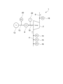
- FIG. 1 is a diagram showing the general configuration of the compressor 1.
- the compressor 1 comprises a compressor body 2, a suction line 4 located upstream of the compressor body 2, and a discharge line 6 located downstream of the compressor body 2.
- the compressor body 2 is a reciprocating compressor and comprises a motor 8 as a power source.
- the motor 8 is connected to the compressor body 2 via a drive shaft 10.
- the motor 8 is driven by power supplied from a power source 12 (e.g., a commercial power source), and the driving force is transmitted to the compressor body 2 via the drive shaft 10.
- a power source 12 e.g., a commercial power source
- a fluid air, refrigerant, etc.
- the compressed fluid generated by the compressor body 2 is discharged via the discharge line 6 toward a supply destination (not shown).
- the suction line 4 is provided with a suction pressure sensor 14 for detecting the pressure of the fluid supplied to the compressor body 2 (hereinafter referred to as "suction pressure ps"), a suction temperature sensor 15 for detecting the temperature of the fluid supplied to the compressor body 2 (hereinafter referred to as “suction temperature Ts"), and a superheat sensor 16 for detecting the superheat Sh of the fluid supplied to the compressor body 2.
- the discharge line 6 is provided with a discharge pressure sensor 18 for detecting the pressure of the fluid discharged from the compressor body 2 (hereinafter referred to as “discharge pressure pd").
- the power supply line 13 for supplying power from the power source 12 to the compressor body 2 is provided with a power sensor 20 for detecting the power consumption Pw or power supply frequency Pf of the compressor body 2.
- the compressor body 2 is also provided with a rotation speed sensor 22 for detecting the rotation speed f of the compressor body 2.
- the detection results of each of these sensors can be output as an electrical signal, which is acquired by the condition monitoring system 100 described below and used for various calculation processes (if there are detection results that are not used by the condition monitoring system 100, the sensor corresponding to that detection result can be omitted as appropriate).
- Figure 2 is a block diagram showing the configuration of the condition monitoring system 100 according to one embodiment.
- the condition monitoring system 100 is composed of, for example, a CPU (Central Processing Unit), RAM (Random Access Memory), ROM (Read Only Memory), and computer-readable storage media.
- a series of processes for realizing various functions are stored in storage media, for example, in the form of a program, and the CPU reads this program into RAM and executes information processing and arithmetic processing to realize various functions.
- the program may be pre-installed in a ROM or other storage medium, provided in a state stored in a computer-readable storage medium, or distributed via wired or wireless communication means.
- Computer-readable storage media include magnetic disks, magneto-optical disks, CD-ROMs, DVD-ROMs, and semiconductor memories.
- the condition monitoring system 100 includes a parameter acquisition unit 102, a factor calculation unit 104, a memory unit 106, a rotation speed acquisition unit 108, a calculation unit 110, and an output unit 112.
- the parameter acquisition unit 102 is configured to acquire a first parameter P1 and a second parameter P2.
- the first parameter P1 is one or more parameters that indicate the operating state of the compressor 1.
- the first parameter P1 includes at least one of the suction pressure ps detected by the suction pressure sensor 14, the discharge pressure pd detected by the discharge pressure sensor 18, the power consumption Pw detected by the power sensor 20, and the power supply frequency Pf.
- the second parameter P2 is a parameter that is correlated with the degree of superheat of the fluid flowing into the compressor 1.
- the second parameter P2 includes at least one of the degree of superheat Sh detected by the superheat sensor 16, and the suction temperature Ts detected by the suction temperature sensor 15.
- the parameter acquisition unit 102 acquires each parameter at a sampling frequency dt [min].
- the numerical range of the sampling frequency dt is not limited, but it is set so that each parameter can be acquired continuously for an appropriate period (e.g., one year or more) to evaluate the lifespan of the compressor 1.
- the suction pressure ps and discharge pressure pd are selected as the first parameter P1, and the superheat degree Sh is selected as the second parameter P2, but other combinations are also possible.
- the suction pressure ps and power consumption Pw may be selected as the first parameter P1, and the suction temperature Ts may be selected as the second parameter P2.
- the discharge pressure pd and power consumption Pw (or power supply frequency Pf) may be selected as the first parameter P1, and the suction temperature Ts may be selected as the second parameter P2.
- the factor calculation unit 104 is configured to calculate a severity factor S based on the first parameter P1 and the second parameter P2 acquired by the parameter acquisition unit 102.
- the severity factor S is an evaluation index corresponding to the life consumption of the valve of the compressor 1, and is calculated based on both the first parameter P1 and the second parameter P2.
- the factor calculation unit 104 calculates the severity factor S using a map M that indicates the relationship between the first parameter P1, the second parameter P2, and the severity factor S.
- the map M is constructed in advance by an experimental, empirical, or simulation method to indicate the relationship between the first parameter P1, the second parameter P2, and the severity factor S, and is stored in a readable manner in a storage unit 106 such as a memory.
- the factor calculation unit 104 obtains the map M by accessing the storage unit 106, and obtains the severity factor S corresponding to the first parameter P1 and the second parameter P2 obtained by the parameter acquisition unit 102 based on the map M. In this way, the factor calculation unit 104 calculates the severity factor S by using such a map M, taking into consideration the nonlinearity of the degree of superheat of the fluid flowing into the compressor 1 with respect to the lifetime consumption amount.
- the rotation speed acquisition unit 108 is configured to acquire the rotation speed f of the compressor body 2.
- the rotation speed f can be acquired as the detection value of the rotation speed sensor 22, as described above.
- the calculation unit 110 is configured to perform various calculations for monitoring the state of the compressor 1 based on the severity factor S calculated by the factor calculation unit 104 and the rotation speed f acquired by the rotation speed acquisition unit 108.
- the calculation unit 110 has multiple function blocks according to the content of the calculation, and specifically has an accumulated life consumption calculation unit 114, a life prediction unit 116, and a maintenance timing recommendation unit 118.
- the accumulated life consumption calculation unit 114 is configured to calculate the accumulated life consumption L in a preset unit period.
- the accumulated life consumption L is found by accumulating the life consumption of the valves included in the compressor body 2 in a unit period, which is calculated using at least the rotation speed f acquired by the rotation speed acquisition unit 108 and the severity factor S calculated by the factor calculation unit 104.
- the life prediction unit 116 is configured to predict the remaining life of the valve of the compressor 1 from the past trend of the accumulated life consumption L.
- the accumulated life consumption L is calculated sequentially by the aforementioned accumulated life consumption calculation unit 114.
- the life prediction unit 116 identifies the past trend of the accumulated life consumption L based on the time trend of the accumulated life consumption L calculated sequentially, and predicts the remaining life based on the past trend. For example, it estimates the future trend of the accumulated life consumption L from the past trend, and predicts the period until the estimated accumulated life consumption L reaches a certain threshold as the remaining life.
- the maintenance timing recommendation unit 118 is configured to calculate the recommended timing for the next maintenance of the compressor 1 that is the monitoring target.
- the recommended timing for the next maintenance is obtained, for example, by subtracting a predetermined period tn as a margin from the life tthr calculated by the life prediction unit 116. This makes it possible to prevent malfunctions and breakdowns by recommending the next maintenance before the timing at which the compressor 1 is likely to actually experience a malfunction or breakdown due to reaching the life tthr.
- the maintenance timing recommendation unit 118 identifies past trends in the accumulated life consumption L based on the time transition of the sequentially calculated accumulated life consumption L, and calculates the recommended timing for the next maintenance based on the past trends. For example, it estimates future transitions in the accumulated life consumption L from the past trends, and calculates the timing at which the estimated accumulated life consumption L reaches a certain threshold as the recommended timing for the next maintenance.
- the output unit 112 is configured to output the calculation results of the calculation unit 110.
- the accumulated life consumption L, remaining life, and recommended time for next maintenance calculated by the calculation unit 110 are output by the output unit 112, and are recognized by an operator of the condition monitoring system 100.
- the accumulated life consumption L and remaining life are displayed in a manner that can be recognized by the operator using a display device such as a display.
- a display device such as a display.
- the operator may be notified that the recommended time for next maintenance has been reached by, for example, an alarm or display.
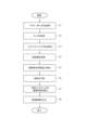
- Figure 3 is a flowchart showing the status monitoring method according to one embodiment.
- the parameter acquisition unit 102 acquires a first parameter P1 and a second parameter P2 (step S1).
- the first parameter P1 can be any one or more parameters related to the operating state of the compressor 1, but in this embodiment, as an example, a case where the suction pressure ps detected by the suction pressure sensor 14 and the discharge pressure pd detected by the discharge pressure sensor 18 are selected as the first parameter P1 is described.
- the second parameter P2 can be any parameter correlated with the degree of superheat of the fluid flowing into the compressor body 2, but in this embodiment, as an example, a case where the superheat Sh detected by the superheat sensor 16 is selected as the second parameter P2 is described.
- the factor calculation unit 104 accesses the storage unit 106 to obtain the map M (step S2).
- the map M is pre-stored in the storage unit 106 and defines the relationship between the first parameter P1, the second parameter P2, and the severity factor S.
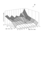
- FIG. 4 is an example of map M obtained in step S2 of FIG. 3.
- map M is shown as a three-dimensional map showing the first parameter P1 on the X-axis, the second parameter P2 on the Y-axis, and the severity factor S on the Z-axis.
- the first parameter P1 and the second parameter P2 are shown one-dimensionally on the X-axis and Y-axis, respectively, but if the first parameter P1 or the second parameter P2 includes multiple parameters, map M may be prepared as a multidimensional map with three or more dimensions.
- the factor calculation unit 104 calculates the severity factor S (step S3).
- step S3 the first parameter P1 and the second parameter P obtained in step S1 are applied to the map M obtained in step S2 to calculate the corresponding severity factor S.
- the severity factor S has a nonlinear behavior with respect to the first parameter P1 and the second parameter P2, but as described above with reference to FIG. 4, by preparing it as the map M, the severity factor S corresponding to the first parameter P1 and the second parameter P2 can be uniquely determined.
- the rotation speed acquisition unit 108 acquires the rotation speed f of the compressor body 2 (step S4).
- the rotation speed acquisition unit 108 can acquire the rotation speed f based on the detection result of the rotation speed sensor 22.
- the cumulative life consumption calculation unit 114 calculates the cumulative life consumption L in a unit period using at least the severity factor S calculated in step S3 and the number of revolutions f acquired in step S4 (step S5). Specifically, the cumulative life consumption L is calculated by the following formula using the sampling frequency dt [min] and the elapsed time ⁇ [min] from the previous maintenance time to the present.
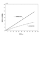
- FIG. 5 shows the time progression of the accumulated life consumption L calculated in step S5 of FIG. 3.
- the accumulated life consumption L calculated in (1) above gradually increases as the operating time of the compressor 1 progresses.
- the time progression of the accumulated life consumption L' calculated based on standard operating conditions is also shown as a comparative example.
- the accumulated life consumption L' is calculated under relatively severe operating conditions, and is shown as a linear function, for example, increasing at a constant rate of change with respect to time.
- the accumulated life consumption L calculated in step S5 is lower than the accumulated life consumption L' based on the standard operating conditions. This means that the calculation takes into account the nonlinear behavior of the severity factor S with respect to the second parameter P2, and does not include an excessive margin compared to the accumulated life consumption L' based on the standard operating conditions, and the state of the compressor 1 is accurately evaluated.
- the life prediction unit 116 predicts the remaining life of the valve of the compressor 1 based on the accumulated life consumption L calculated in step S5 (step S6).
- the remaining life is predicted by identifying past trends from the time progression of the accumulated life consumption L, and estimating the future accumulated life consumption L from the past trends.
- FIG. 6 is a diagram showing how to estimate future accumulated lifetime consumption L from the past trend of accumulated lifetime consumption L.
- the horizontal axis represents time, and data is acquired and calculated on a daily basis.
- the above steps S1 to S5 are repeated to obtain accumulated lifetime consumption L for 30 days from time t i-30 to time t i (present).
- the life prediction unit 116 approximates the past trend during that period with a linear function, and calculates the linear coefficient ⁇ i as the life consumption rate during that period using the following formula.
- L i-30 is the cumulative lifetime consumption corresponding to time t i-30
- L i is the cumulative lifetime consumption corresponding to time t i .
- the life prediction unit 116 predicts the future transition of the accumulated life consumption L by using the life increase rate ⁇ i obtained by the above formula (2). Specifically, as shown by the dashed line in Fig. 6, the future transition of the accumulated life consumption L is predicted by assuming that the linear function behavior identified as the past trend will continue in the future. Then, the life prediction unit 116 predicts the future transition of the accumulated life consumption L by using the following formula as the time when a reference value of the accumulated life consumption corresponding to a preset life (hereinafter, appropriately referred to as "accumulated life consumption threshold L thr ”) is reached.
- the maintenance timing recommendation unit 118 calculates the recommended timing for the next maintenance (step S7).
- the recommended timing for the next maintenance tm can be calculated, for example, by subtracting a predetermined period tn from the life tthr calculated in step S6, using the following formula:
- the recommended timing tm is obtained as a timing that can secure a margin of a predetermined period tn from the life tthr . This makes it possible to prevent malfunctions and breakdowns by recommending the next maintenance before the timing when the compressor 1 is likely to actually experience a malfunction or breakdown due to reaching the life tthr .
- the output unit 112 then outputs the calculation result (step S8).
- the calculation result output in step S8 includes, for example, at least one of the cumulative lifetime consumption amount L calculated in step S5, the lifetime t thr calculated in step S6, and the recommended timing t m for the next maintenance calculated in step S7.
- the above steps corresponding to the calculation results not included in the output result in step S8 can be omitted as appropriate.
- a severity factor which is an evaluation index corresponding to the life consumption of the compressor valve, is calculated based on both a first parameter indicating the operating state and a second parameter correlated with the degree of superheat of the fluid flowing into the compressor.
- the severity factor is calculated using a map indicating the relationship between the first parameter, the second parameter, and the severity factor, taking into account the nonlinearity of the degree of superheat of the fluid flowing into the compressor with respect to the life consumption.
- a status monitoring system includes: 1.
- a compressor valve condition monitoring system comprising: a parameter acquisition unit for acquiring one or more first parameters indicating an operating state of the compressor and a second parameter correlated with a degree of superheat of a fluid flowing into the compressor; a factor calculation unit for calculating the severity factor corresponding to the first parameter and the second parameter from a map that defines a relationship between the first parameter, the second parameter, and a severity factor indicating a life consumption level of the valve; a calculation unit for calculating an integrated service life consumption by integrating a service life consumption of the valve in the unit period, the service life consumption being calculated using at least a length of a unit period, a rotation speed of the compressor for each unit period, and the severity factor; Equipped with.
- a severity factor which is an evaluation index corresponding to the life consumption of the compressor valve, is calculated based on both a first parameter indicating the operating state and a second parameter correlated with the degree of superheat of the fluid flowing into the compressor.
- the severity factor is calculated using a map indicating the relationship between the first parameter, the second parameter, and the severity factor, taking into account the nonlinearity of the degree of superheat of the fluid flowing into the compressor with respect to the life consumption.
- the valve further includes a life prediction unit for predicting a remaining life of the valve from a past trend of the integrated life consumption amount.
- the accumulated life consumption is calculated sequentially, and the future trend of the accumulated life consumption is calculated based on the past trend, thereby making it possible to appropriately predict the remaining life of the valve.
- the life prediction unit identifies the past trend based on a life consumption increase rate of the integrated life consumption over a predetermined period.
- the life consumption increase rate which is the amount of change in the integrated life consumption over a specified period of time, it is possible to suitably estimate past trends for predicting the remaining life of the valve.
- the device further includes a maintenance timing recommendation unit that calculates a recommended timing for the next maintenance based on the remaining life.
- the recommended timing for the next maintenance can be appropriately determined based on the remaining life of the compressor.
- the compressor includes a calculation unit which compares a maintenance timing previously set for the compressor with the recommended next maintenance timing, selects the shorter time, and notifies the user.
- the maintenance timing previously set for the compressor is compared with the recommended next maintenance timing calculated based on the remaining life, and the shorter timing is notified, thereby making it possible to appropriately inform the user of the required maintenance timing.
- the first parameters include a suction pressure and a discharge pressure of the compressor.
- the suction pressure and discharge pressure of the compressor are used as the first parameter, making it possible to appropriately grasp the operating state of the compressor.
- the compressor is a reciprocating compressor.
- the state of the valves used in the reciprocating compressor can be appropriately monitored based on the accumulated life consumption.
- a status monitoring method includes: 1. A method for monitoring a condition of a compressor valve, comprising: obtaining one or more first parameters indicative of an operating state of the compressor and a second parameter correlated with a degree of superheat of a fluid entering the compressor; calculating the severity factor corresponding to the first parameter and the second parameter from a map that defines a relationship between the first parameter, the second parameter, and a severity factor indicating a life consumption level of the valve; calculating an integrated service life consumption by integrating the service life consumption of the valve in the unit period calculated using at least the length of the unit period, the number of revolutions of the compressor for each unit period, and the severity factor; Equipped with.
- a severity factor which is an evaluation index corresponding to the life consumption of the compressor valve, is calculated based on both a first parameter indicating the operating state and a second parameter correlated with the degree of superheat of the fluid flowing into the compressor.
- the severity factor is calculated using a map indicating the relationship between the first parameter, the second parameter, and the severity factor, taking into account the nonlinearity of the degree of superheat of the fluid flowing into the compressor with respect to the life consumption.
Landscapes
- Engineering & Computer Science (AREA)
- Mechanical Engineering (AREA)
- General Engineering & Computer Science (AREA)
- Physics & Mathematics (AREA)
- General Physics & Mathematics (AREA)
- Computer Hardware Design (AREA)
- Control Of Positive-Displacement Pumps (AREA)
- Testing Of Devices, Machine Parts, Or Other Structures Thereof (AREA)
Abstract
Description
圧縮機のバルブの状態監視システムであって、
前記圧縮機の運転状態を示す1以上の第1パラメータ、及び、前記圧縮機に流入する流体の過熱度と相関のある第2パラメータを取得するためのパラメータ取得部と、
前記第1パラメータ及び前記第2パラメータと、前記バルブの寿命消費レベルを示すシビアリティファクタとの関係を規定するマップから、前記第1パラメータ及び前記第2パラメータに対応する前記シビアリティファクタを算出するためのファクタ算出部と、
単位期間の長さ、前記単位期間ごとの前記圧縮機の回転数、及び、前記シビアリティファクタを少なくとも用いて算出される前記単位期間における前記バルブの寿命消費量を積算することで積算寿命消費量を算出するための演算部と、
を備える。
圧縮機のバルブの状態監視方法であって、
前記圧縮機の運転状態を示す1以上の第1パラメータ、及び、前記圧縮機に流入する流体の過熱度と相関のある第2パラメータを取得する工程と、
前記第1パラメータ及び前記第2パラメータと、前記バルブの寿命消費レベルを示すシビアリティファクタとの関係を規定するマップから、前記第1パラメータ及び前記第2パラメータに対応する前記シビアリティファクタを算出する工程と、
単位期間の長さ、前記単位期間ごとの前記圧縮機の回転数、及び、前記シビアリティファクタを少なくとも用いて算出される前記単位期間における前記バルブの寿命消費量を積算することで積算寿命消費量を算出する工程と、
を備える。
出力部112は、演算部110における演算結果を出力するための構成である。演算部110で算出される前述の積算寿命消費量L、余寿命、及び、次回メンテナンスの推奨時期は、出力部112によって出力されることで、状態監視システム100のオペレータに認識される。例えば、積算寿命消費量Lや余寿命は、ディスプレイ等の表示装置を用いて、オペレータが認識可能な態様で表示される。また次回メンテナンスの推奨時期については、当該時期に到達した際に例えばアラームや表示によって、次回メンテナンスの推奨時期に到達した旨をオペレータに報知してもよい。




尚、ステップS8で出力結果に含まれない演算結果に対応する上記ステップは適宜省略可能である。
圧縮機のバルブの状態監視システムであって、
前記圧縮機の運転状態を示す1以上の第1パラメータ、及び、前記圧縮機に流入する流体の過熱度と相関のある第2パラメータを取得するためのパラメータ取得部と、
前記第1パラメータ及び前記第2パラメータと、前記バルブの寿命消費レベルを示すシビアリティファクタとの関係を規定するマップから、前記第1パラメータ及び前記第2パラメータに対応する前記シビアリティファクタを算出するためのファクタ算出部と、
単位期間の長さ、前記単位期間ごとの前記圧縮機の回転数、及び、前記シビアリティファクタを少なくとも用いて算出される前記単位期間における前記バルブの寿命消費量を積算することで積算寿命消費量を算出するための演算部と、
を備える。
前記積算寿命消費量の過去のトレンドから前記バルブの余寿命を予測するための寿命予測部を更に備える。
前記寿命予測部は、前記積算寿命消費量の所定期間における寿命消費量増加率に基づいて、前記過去トレンドを特定する。
前記余寿命に基づいて次回メンテナンスの推奨時期を算出するメンテナンス時期推奨部を更に備える。
予め圧縮機に定められたメンテナンス時期と前記次回メンテナンスの推奨時期とを比較し、短い方の時間を選択して通知する演算部を備える。
前記第1パラメータは前記圧縮機の吸入圧力及び吐出圧力を含む。
前記圧縮機はレシプロ圧縮機である。
圧縮機のバルブの状態監視方法であって、
前記圧縮機の運転状態を示す1以上の第1パラメータ、及び、前記圧縮機に流入する流体の過熱度と相関のある第2パラメータを取得する工程と、
前記第1パラメータ及び前記第2パラメータと、前記バルブの寿命消費レベルを示すシビアリティファクタとの関係を規定するマップから、前記第1パラメータ及び前記第2パラメータに対応する前記シビアリティファクタを算出する工程と、
単位期間の長さ、前記単位期間ごとの前記圧縮機の回転数、及び、前記シビアリティファクタを少なくとも用いて算出される前記単位期間における前記バルブの寿命消費量を積算することで積算寿命消費量を算出する工程と、
を備える。
2 圧縮機本体
4 吸入ライン
6 吐出ライン
8 モータ
10 駆動軸
12 電力源
13 電力供給ライン
14 吸入圧力センサ
15 吸入温度センサ
16 過熱度センサ
18 吐出圧力センサ
20 電力センサ
22 回転数センサ
100 状態監視システム
102 パラメータ取得部
104 ファクタ算出部
106 記憶部
108 回転数取得部
110 演算部
112 出力部
114 積算寿命消費量算出部
116 寿命予測部
118 メンテナンス時期推奨部
L 積算寿命消費量
Lthr 積算寿命消費量閾値
M マップ
P1 第1パラメータ
P2 第2パラメータ
S シビアリティファクタ
Claims (8)
- 圧縮機のバルブの状態監視システムであって、
前記圧縮機の運転状態を示す1以上の第1パラメータ、及び、前記圧縮機に流入する流体の過熱度と相関のある第2パラメータを取得するためのパラメータ取得部と、
前記第1パラメータ及び前記第2パラメータと、前記バルブの寿命消費レベルを示すシビアリティファクタとの関係を規定するマップから、前記第1パラメータ及び前記第2パラメータに対応する前記シビアリティファクタを算出するためのファクタ算出部と、
単位期間の長さ、前記単位期間ごとの前記圧縮機の回転数、及び、前記シビアリティファクタを少なくとも用いて算出される前記単位期間における前記バルブの寿命消費量を積算することで積算寿命消費量を算出するための演算部と、
を備える、状態監視システム。 - 前記積算寿命消費量の過去のトレンドから前記バルブの余寿命を予測するための寿命予測部を更に備える、請求項1に記載の状態監視システム。
- 前記寿命予測部は、前記積算寿命消費量の所定期間における寿命消費量増加率に基づいて、前記過去トレンドを特定する、請求項2に記載の状態監視システム。
- 前記余寿命に基づいて次回メンテナンスの推奨時期を算出するメンテナンス時期推奨部を更に備える、請求項2に記載の状態監視システム。
- 予め圧縮機に定められたメンテナンス時期と前記次回メンテナンスの推奨時期とを比較し、短い方の時間を選択して通知する演算部を備えた、請求項4に記載の状態監視システム。
- 前記第1パラメータは前記圧縮機の吸入圧力及び吐出圧力を含む、請求項1又は2に記載の状態監視システム。
- 前記圧縮機はレシプロ圧縮機である、請求項1又は2に記載の状態監視システム。
- 圧縮機のバルブの状態監視方法であって、
前記圧縮機の運転状態を示す1以上の第1パラメータ、及び、前記圧縮機に流入する流体の過熱度と相関のある第2パラメータを取得する工程と、
前記第1パラメータ及び前記第2パラメータと、前記バルブの寿命消費レベルを示すシビアリティファクタとの関係を規定するマップから、前記第1パラメータ及び前記第2パラメータに対応する前記シビアリティファクタを取得する工程と、
単位期間の長さ、前記単位期間ごとの前記圧縮機の回転数、及び、前記シビアリティファクタを少なくとも用いて算出される前記単位期間における前記バルブの寿命消費量を積算することで積算寿命消費量を算出する工程と、
を備える、状態監視方法。
Priority Applications (2)
| Application Number | Priority Date | Filing Date | Title |
|---|---|---|---|
| EP23872052.8A EP4579081A4 (en) | 2022-09-30 | 2023-09-19 | STATE MONITORING SYSTEM AND STATE MONITORING METHOD |
| AU2023350505A AU2023350505A1 (en) | 2022-09-30 | 2023-09-19 | State monitoring system and state monitoring method |
Applications Claiming Priority (2)
| Application Number | Priority Date | Filing Date | Title |
|---|---|---|---|
| JP2022-157766 | 2022-09-30 | ||
| JP2022157766A JP2024051545A (ja) | 2022-09-30 | 2022-09-30 | 状態監視システム及び状態監視方法 |
Publications (1)
| Publication Number | Publication Date |
|---|---|
| WO2024070824A1 true WO2024070824A1 (ja) | 2024-04-04 |
Family
ID=90477519
Family Applications (1)
| Application Number | Title | Priority Date | Filing Date |
|---|---|---|---|
| PCT/JP2023/033960 Ceased WO2024070824A1 (ja) | 2022-09-30 | 2023-09-19 | 状態監視システム及び状態監視方法 |
Country Status (5)
| Country | Link |
|---|---|
| EP (1) | EP4579081A4 (ja) |
| JP (1) | JP2024051545A (ja) |
| AU (1) | AU2023350505A1 (ja) |
| TW (1) | TWI875205B (ja) |
| WO (1) | WO2024070824A1 (ja) |
Cited By (1)
| Publication number | Priority date | Publication date | Assignee | Title |
|---|---|---|---|---|
| CN120507124A (zh) * | 2025-07-21 | 2025-08-19 | 南京普瑞泰格安全设备工程有限公司 | 一种呼吸阀智能监测系统、呼吸阀及管理平台 |
Citations (2)
| Publication number | Priority date | Publication date | Assignee | Title |
|---|---|---|---|---|
| JP6306740B2 (ja) | 2014-11-27 | 2018-04-04 | 株式会社日立産機システム | 圧縮機 |
| JP2020154662A (ja) * | 2019-03-19 | 2020-09-24 | ダイキン工業株式会社 | 保守作業支援装置、保守作業支援方法及び保守作業支援プログラム |
Family Cites Families (7)
| Publication number | Priority date | Publication date | Assignee | Title |
|---|---|---|---|---|
| CN102182671B (zh) * | 2011-05-26 | 2013-09-18 | 徐州工程学院 | 一种气体压缩机的状态分析监测方法 |
| JP5619884B2 (ja) * | 2011-05-31 | 2014-11-05 | 日立アプライアンス株式会社 | 冷凍装置の異常検出方法及びその装置 |
| DE102013211292A1 (de) * | 2013-06-17 | 2014-12-18 | J.P. Sauer & Sohn Maschinenbau Gmbh | Verfahren zum Betrieb und zur Wartung eines Kompressors |
| EP3095654B1 (en) * | 2015-05-19 | 2017-12-27 | KNORR-BREMSE Systeme für Nutzfahrzeuge GmbH | Prediction of remaining lifetime for compressed air supply system component |
| TWI721451B (zh) * | 2019-06-13 | 2021-03-11 | 周文三 | 具有警示音聲及兼具洩壓功能之空氣壓縮機 |
| CN113653630B (zh) * | 2021-08-24 | 2023-06-02 | 中石化石油机械股份有限公司三机分公司 | 一种压缩机润滑系统性能检测和故障预警的方法 |
| CN114509286A (zh) * | 2022-02-23 | 2022-05-17 | 一汽解放汽车有限公司 | 一种车辆空气处理单元的诊断装置、诊断方法和应用 |
-
2022
- 2022-09-30 JP JP2022157766A patent/JP2024051545A/ja active Pending
-
2023
- 2023-09-19 WO PCT/JP2023/033960 patent/WO2024070824A1/ja not_active Ceased
- 2023-09-19 EP EP23872052.8A patent/EP4579081A4/en active Pending
- 2023-09-19 AU AU2023350505A patent/AU2023350505A1/en active Pending
- 2023-09-22 TW TW112136204A patent/TWI875205B/zh active
Patent Citations (2)
| Publication number | Priority date | Publication date | Assignee | Title |
|---|---|---|---|---|
| JP6306740B2 (ja) | 2014-11-27 | 2018-04-04 | 株式会社日立産機システム | 圧縮機 |
| JP2020154662A (ja) * | 2019-03-19 | 2020-09-24 | ダイキン工業株式会社 | 保守作業支援装置、保守作業支援方法及び保守作業支援プログラム |
Non-Patent Citations (1)
| Title |
|---|
| See also references of EP4579081A4 |
Cited By (1)
| Publication number | Priority date | Publication date | Assignee | Title |
|---|---|---|---|---|
| CN120507124A (zh) * | 2025-07-21 | 2025-08-19 | 南京普瑞泰格安全设备工程有限公司 | 一种呼吸阀智能监测系统、呼吸阀及管理平台 |
Also Published As
| Publication number | Publication date |
|---|---|
| TW202424356A (zh) | 2024-06-16 |
| EP4579081A1 (en) | 2025-07-02 |
| JP2024051545A (ja) | 2024-04-11 |
| TWI875205B (zh) | 2025-03-01 |
| AU2023350505A1 (en) | 2025-04-03 |
| EP4579081A4 (en) | 2025-08-27 |
Similar Documents
| Publication | Publication Date | Title |
|---|---|---|
| EP3964703B1 (en) | Engine lubrication oil consumption and condition monitoring | |
| KR102908587B1 (ko) | 엔진 오일 열화 감지 방법 및 시스템 | |
| JP6797528B2 (ja) | 監視装置及び監視方法 | |
| US6577959B1 (en) | Fluid level measuring system for machines | |
| RU2604659C2 (ru) | Диагностика стартера | |
| US9512851B2 (en) | Electronic apparatus with fan motor | |
| WO2024070824A1 (ja) | 状態監視システム及び状態監視方法 | |
| KR20200019976A (ko) | 감시 장치, 감시 방법, 프로그램 | |
| CN108146343A (zh) | 预警系统及预警方法 | |
| JP4341779B2 (ja) | 空調機の異常検知装置及び異常検知方法 | |
| JP2003254253A (ja) | 圧縮機およびそのメインテナンス方法 | |
| US20190033190A1 (en) | Method for determining the viscosity of a conveying fluid conveyed by means of a pump | |
| CN116964327A (zh) | 用于位于润滑/冷却组件内的智能泵的控制系统 | |
| CN112585359B (zh) | 用于检测旋转的机器的运行状态的方法 | |
| US10288061B2 (en) | Method and system for protection and diagnosis of a linear compressor, and a linear compressor | |
| JP6987280B2 (ja) | 診断システム及び冷凍サイクル装置 | |
| US11881802B2 (en) | Method for detecting condensate formation which is imminent or has already taken place on/in electric motors, and method for avoiding corresponding condensate formation and/or for eliminating/reducing condensate on/in electric motors | |
| CN110084454B (zh) | 在线评估部件使用情况的系统和方法 | |
| CN115111163A (zh) | 压缩机保护模块及保护方法 | |
| KR20210133657A (ko) | 엔진오일 교환 감지 장치 및 방법 | |
| JP7698538B2 (ja) | 情報処理装置、プログラム、異常検知方法、異常検知システム、及び冷却貯蔵庫 | |
| US20260078871A1 (en) | Lubrication health monitoring system | |
| JP2005180203A (ja) | 真空ポンプの故障データ保存システム | |
| JP2006017122A (ja) | エンジンなどの状態監視方法及びシステム | |
| WO2013068022A1 (en) | Oil change detecting method |
Legal Events
| Date | Code | Title | Description |
|---|---|---|---|
| 121 | Ep: the epo has been informed by wipo that ep was designated in this application |
Ref document number: 23872052 Country of ref document: EP Kind code of ref document: A1 |
|
| WWE | Wipo information: entry into national phase |
Ref document number: 819635 Country of ref document: NZ Ref document number: AU2023350505 Country of ref document: AU |
|
| WWE | Wipo information: entry into national phase |
Ref document number: 2023872052 Country of ref document: EP |
|
| WWP | Wipo information: published in national office |
Ref document number: 819635 Country of ref document: NZ |
|
| ENP | Entry into the national phase |
Ref document number: 2023872052 Country of ref document: EP Effective date: 20250324 |
|
| ENP | Entry into the national phase |
Ref document number: 2023350505 Country of ref document: AU Date of ref document: 20230919 Kind code of ref document: A |
|
| NENP | Non-entry into the national phase |
Ref country code: DE |
|
| WWP | Wipo information: published in national office |
Ref document number: 2023872052 Country of ref document: EP |