WO2024071003A1 - 冷凍サイクル装置 - Google Patents
冷凍サイクル装置 Download PDFInfo
- Publication number
- WO2024071003A1 WO2024071003A1 PCT/JP2023/034635 JP2023034635W WO2024071003A1 WO 2024071003 A1 WO2024071003 A1 WO 2024071003A1 JP 2023034635 W JP2023034635 W JP 2023034635W WO 2024071003 A1 WO2024071003 A1 WO 2024071003A1
- Authority
- WO
- WIPO (PCT)
- Prior art keywords
- refrigerant
- composition
- refrigeration cycle
- mixed refrigerant
- accumulator
- Prior art date
- Legal status (The legal status is an assumption and is not a legal conclusion. Google has not performed a legal analysis and makes no representation as to the accuracy of the status listed.)
- Ceased
Links
Images

Classifications
-
- C—CHEMISTRY; METALLURGY
- C09—DYES; PAINTS; POLISHES; NATURAL RESINS; ADHESIVES; COMPOSITIONS NOT OTHERWISE PROVIDED FOR; APPLICATIONS OF MATERIALS NOT OTHERWISE PROVIDED FOR
- C09K—MATERIALS FOR MISCELLANEOUS APPLICATIONS, NOT PROVIDED FOR ELSEWHERE
- C09K5/00—Heat-transfer, heat-exchange or heat-storage materials, e.g. refrigerants; Materials for the production of heat or cold by chemical reactions other than by combustion
- C09K5/02—Materials undergoing a change of physical state when used
- C09K5/04—Materials undergoing a change of physical state when used the change of state being from liquid to vapour or vice versa
- C09K5/041—Materials undergoing a change of physical state when used the change of state being from liquid to vapour or vice versa for compression-type refrigeration systems
- C09K5/044—Materials undergoing a change of physical state when used the change of state being from liquid to vapour or vice versa for compression-type refrigeration systems comprising halogenated compounds
- C09K5/045—Materials undergoing a change of physical state when used the change of state being from liquid to vapour or vice versa for compression-type refrigeration systems comprising halogenated compounds containing only fluorine as halogen
-
- F—MECHANICAL ENGINEERING; LIGHTING; HEATING; WEAPONS; BLASTING
- F25—REFRIGERATION OR COOLING; COMBINED HEATING AND REFRIGERATION SYSTEMS; HEAT PUMP SYSTEMS; MANUFACTURE OR STORAGE OF ICE; LIQUEFACTION SOLIDIFICATION OF GASES
- F25B—REFRIGERATION MACHINES, PLANTS OR SYSTEMS; COMBINED HEATING AND REFRIGERATION SYSTEMS; HEAT PUMP SYSTEMS
- F25B43/00—Arrangements for separating or purifying gases or liquids; Arrangements for vaporising the residuum of liquid refrigerant, e.g. by heat
- F25B43/006—Accumulators
-
- F—MECHANICAL ENGINEERING; LIGHTING; HEATING; WEAPONS; BLASTING
- F25—REFRIGERATION OR COOLING; COMBINED HEATING AND REFRIGERATION SYSTEMS; HEAT PUMP SYSTEMS; MANUFACTURE OR STORAGE OF ICE; LIQUEFACTION SOLIDIFICATION OF GASES
- F25B—REFRIGERATION MACHINES, PLANTS OR SYSTEMS; COMBINED HEATING AND REFRIGERATION SYSTEMS; HEAT PUMP SYSTEMS
- F25B13/00—Compression machines, plants or systems, with reversible cycle
-
- F—MECHANICAL ENGINEERING; LIGHTING; HEATING; WEAPONS; BLASTING
- F25—REFRIGERATION OR COOLING; COMBINED HEATING AND REFRIGERATION SYSTEMS; HEAT PUMP SYSTEMS; MANUFACTURE OR STORAGE OF ICE; LIQUEFACTION SOLIDIFICATION OF GASES
- F25B—REFRIGERATION MACHINES, PLANTS OR SYSTEMS; COMBINED HEATING AND REFRIGERATION SYSTEMS; HEAT PUMP SYSTEMS
- F25B49/00—Arrangement or mounting of control or safety devices
- F25B49/02—Arrangement or mounting of control or safety devices for compression type machines, plants or systems
-
- C—CHEMISTRY; METALLURGY
- C09—DYES; PAINTS; POLISHES; NATURAL RESINS; ADHESIVES; COMPOSITIONS NOT OTHERWISE PROVIDED FOR; APPLICATIONS OF MATERIALS NOT OTHERWISE PROVIDED FOR
- C09K—MATERIALS FOR MISCELLANEOUS APPLICATIONS, NOT PROVIDED FOR ELSEWHERE
- C09K2205/00—Aspects relating to compounds used in compression type refrigeration systems
- C09K2205/10—Components
- C09K2205/12—Hydrocarbons
- C09K2205/126—Unsaturated fluorinated hydrocarbons
-
- C—CHEMISTRY; METALLURGY
- C09—DYES; PAINTS; POLISHES; NATURAL RESINS; ADHESIVES; COMPOSITIONS NOT OTHERWISE PROVIDED FOR; APPLICATIONS OF MATERIALS NOT OTHERWISE PROVIDED FOR
- C09K—MATERIALS FOR MISCELLANEOUS APPLICATIONS, NOT PROVIDED FOR ELSEWHERE
- C09K2205/00—Aspects relating to compounds used in compression type refrigeration systems
- C09K2205/22—All components of a mixture being fluoro compounds
-
- C—CHEMISTRY; METALLURGY
- C09—DYES; PAINTS; POLISHES; NATURAL RESINS; ADHESIVES; COMPOSITIONS NOT OTHERWISE PROVIDED FOR; APPLICATIONS OF MATERIALS NOT OTHERWISE PROVIDED FOR
- C09K—MATERIALS FOR MISCELLANEOUS APPLICATIONS, NOT PROVIDED FOR ELSEWHERE
- C09K2205/00—Aspects relating to compounds used in compression type refrigeration systems
- C09K2205/34—The mixture being non-azeotropic
-
- F—MECHANICAL ENGINEERING; LIGHTING; HEATING; WEAPONS; BLASTING
- F25—REFRIGERATION OR COOLING; COMBINED HEATING AND REFRIGERATION SYSTEMS; HEAT PUMP SYSTEMS; MANUFACTURE OR STORAGE OF ICE; LIQUEFACTION SOLIDIFICATION OF GASES
- F25B—REFRIGERATION MACHINES, PLANTS OR SYSTEMS; COMBINED HEATING AND REFRIGERATION SYSTEMS; HEAT PUMP SYSTEMS
- F25B2345/00—Details for charging or discharging refrigerants; Service stations therefor
- F25B2345/001—Charging refrigerant to a cycle
-
- F—MECHANICAL ENGINEERING; LIGHTING; HEATING; WEAPONS; BLASTING
- F25—REFRIGERATION OR COOLING; COMBINED HEATING AND REFRIGERATION SYSTEMS; HEAT PUMP SYSTEMS; MANUFACTURE OR STORAGE OF ICE; LIQUEFACTION SOLIDIFICATION OF GASES
- F25B—REFRIGERATION MACHINES, PLANTS OR SYSTEMS; COMBINED HEATING AND REFRIGERATION SYSTEMS; HEAT PUMP SYSTEMS
- F25B2400/00—Component parts or details not otherwise provided for in this subclass
- F25B2400/12—Inflammable refrigerants
- F25B2400/121—Inflammable refrigerants using R1234
-
- F—MECHANICAL ENGINEERING; LIGHTING; HEATING; WEAPONS; BLASTING
- F25—REFRIGERATION OR COOLING; COMBINED HEATING AND REFRIGERATION SYSTEMS; HEAT PUMP SYSTEMS; MANUFACTURE OR STORAGE OF ICE; LIQUEFACTION SOLIDIFICATION OF GASES
- F25B—REFRIGERATION MACHINES, PLANTS OR SYSTEMS; COMBINED HEATING AND REFRIGERATION SYSTEMS; HEAT PUMP SYSTEMS
- F25B2500/00—Problems to be solved
- F25B2500/19—Calculation of parameters
-
- F—MECHANICAL ENGINEERING; LIGHTING; HEATING; WEAPONS; BLASTING
- F25—REFRIGERATION OR COOLING; COMBINED HEATING AND REFRIGERATION SYSTEMS; HEAT PUMP SYSTEMS; MANUFACTURE OR STORAGE OF ICE; LIQUEFACTION SOLIDIFICATION OF GASES
- F25B—REFRIGERATION MACHINES, PLANTS OR SYSTEMS; COMBINED HEATING AND REFRIGERATION SYSTEMS; HEAT PUMP SYSTEMS
- F25B2600/00—Control issues
-
- F—MECHANICAL ENGINEERING; LIGHTING; HEATING; WEAPONS; BLASTING
- F25—REFRIGERATION OR COOLING; COMBINED HEATING AND REFRIGERATION SYSTEMS; HEAT PUMP SYSTEMS; MANUFACTURE OR STORAGE OF ICE; LIQUEFACTION SOLIDIFICATION OF GASES
- F25B—REFRIGERATION MACHINES, PLANTS OR SYSTEMS; COMBINED HEATING AND REFRIGERATION SYSTEMS; HEAT PUMP SYSTEMS
- F25B2600/00—Control issues
- F25B2600/02—Compressor control
- F25B2600/025—Compressor control by controlling speed
- F25B2600/0253—Compressor control by controlling speed with variable speed
-
- F—MECHANICAL ENGINEERING; LIGHTING; HEATING; WEAPONS; BLASTING
- F25—REFRIGERATION OR COOLING; COMBINED HEATING AND REFRIGERATION SYSTEMS; HEAT PUMP SYSTEMS; MANUFACTURE OR STORAGE OF ICE; LIQUEFACTION SOLIDIFICATION OF GASES
- F25B—REFRIGERATION MACHINES, PLANTS OR SYSTEMS; COMBINED HEATING AND REFRIGERATION SYSTEMS; HEAT PUMP SYSTEMS
- F25B2600/00—Control issues
- F25B2600/05—Refrigerant levels
-
- F—MECHANICAL ENGINEERING; LIGHTING; HEATING; WEAPONS; BLASTING
- F25—REFRIGERATION OR COOLING; COMBINED HEATING AND REFRIGERATION SYSTEMS; HEAT PUMP SYSTEMS; MANUFACTURE OR STORAGE OF ICE; LIQUEFACTION SOLIDIFICATION OF GASES
- F25B—REFRIGERATION MACHINES, PLANTS OR SYSTEMS; COMBINED HEATING AND REFRIGERATION SYSTEMS; HEAT PUMP SYSTEMS
- F25B2600/00—Control issues
- F25B2600/11—Fan speed control
- F25B2600/111—Fan speed control of condenser fans
-
- F—MECHANICAL ENGINEERING; LIGHTING; HEATING; WEAPONS; BLASTING
- F25—REFRIGERATION OR COOLING; COMBINED HEATING AND REFRIGERATION SYSTEMS; HEAT PUMP SYSTEMS; MANUFACTURE OR STORAGE OF ICE; LIQUEFACTION SOLIDIFICATION OF GASES
- F25B—REFRIGERATION MACHINES, PLANTS OR SYSTEMS; COMBINED HEATING AND REFRIGERATION SYSTEMS; HEAT PUMP SYSTEMS
- F25B2600/00—Control issues
- F25B2600/11—Fan speed control
- F25B2600/112—Fan speed control of evaporator fans
-
- F—MECHANICAL ENGINEERING; LIGHTING; HEATING; WEAPONS; BLASTING
- F25—REFRIGERATION OR COOLING; COMBINED HEATING AND REFRIGERATION SYSTEMS; HEAT PUMP SYSTEMS; MANUFACTURE OR STORAGE OF ICE; LIQUEFACTION SOLIDIFICATION OF GASES
- F25B—REFRIGERATION MACHINES, PLANTS OR SYSTEMS; COMBINED HEATING AND REFRIGERATION SYSTEMS; HEAT PUMP SYSTEMS
- F25B2600/00—Control issues
- F25B2600/25—Control of valves
- F25B2600/2513—Expansion valves
-
- F—MECHANICAL ENGINEERING; LIGHTING; HEATING; WEAPONS; BLASTING
- F25—REFRIGERATION OR COOLING; COMBINED HEATING AND REFRIGERATION SYSTEMS; HEAT PUMP SYSTEMS; MANUFACTURE OR STORAGE OF ICE; LIQUEFACTION SOLIDIFICATION OF GASES
- F25B—REFRIGERATION MACHINES, PLANTS OR SYSTEMS; COMBINED HEATING AND REFRIGERATION SYSTEMS; HEAT PUMP SYSTEMS
- F25B2700/00—Sensing or detecting of parameters; Sensors therefor
- F25B2700/04—Refrigerant level
-
- F—MECHANICAL ENGINEERING; LIGHTING; HEATING; WEAPONS; BLASTING
- F25—REFRIGERATION OR COOLING; COMBINED HEATING AND REFRIGERATION SYSTEMS; HEAT PUMP SYSTEMS; MANUFACTURE OR STORAGE OF ICE; LIQUEFACTION SOLIDIFICATION OF GASES
- F25B—REFRIGERATION MACHINES, PLANTS OR SYSTEMS; COMBINED HEATING AND REFRIGERATION SYSTEMS; HEAT PUMP SYSTEMS
- F25B45/00—Arrangements for charging or discharging refrigerant
Definitions
- Patent Document 1 JP Patent Publication 2015-200431 A discloses an air conditioner that is a refrigeration cycle device that has an accumulator connected to the suction side of a compressor and uses a non-azeotropic refrigerant mixture that is a mixture of a low boiling point refrigerant and a high boiling point refrigerant.
- the excess refrigerant that accumulates in the accumulator becomes a liquid refrigerant that contains a large amount of high-boiling-point refrigerant, and the circulating refrigerant that circulates through the refrigerant circuit of the refrigeration cycle device tends to be a refrigerant that contains a large amount of low-boiling-point refrigerant.
- the composition of the circulating refrigerant may deviate from the base composition of the non-azeotropic refrigerant mixture, which may reduce the heat exchange performance and controllability of the refrigeration cycle device.
- the refrigeration cycle device of the first aspect includes a compressor, a condenser, an expansion mechanism, an evaporator, an accumulator, and a refrigerant circuit.
- the compressor, the condenser, the expansion mechanism, the evaporator, and the accumulator are connected in a ring shape in the refrigerant circuit.
- a mixed refrigerant is sealed in the refrigerant circuit.
- the mixed refrigerant is a non-azeotropic mixed refrigerant.
- a first value obtained by subtracting the second amount from the first amount and dividing the result by the first amount exceeds a value determined according to the mixed refrigerant.
- the first amount is the amount of the mixed refrigerant sealed in the refrigerant circuit.
- the second amount is the amount of liquid refrigerant stored in the accumulator.
- the amount of liquid refrigerant stored in the accumulator is limited according to the type and amount of refrigerant charged in the refrigerant circuit. This prevents the composition of the refrigerant circulating in the refrigerant circuit from deviating from the base composition of the non-azeotropic refrigerant mixture charged in the refrigerant circuit.
- the refrigeration cycle device of the second aspect is the refrigeration cycle device of the first aspect, in which the second quantity is the product of the effective volume of the accumulator and the saturated liquid density of the mixed refrigerant at the pressure of the mixed refrigerant sucked into the compressor.
- the refrigeration cycle device of the third aspect is the refrigeration cycle device of the first or second aspect, in which the mixed refrigerant sealed in the refrigerant circuit has a first composition.
- the mixed refrigerant circulating in the refrigerant circuit has a second composition.
- the first value is set so that the second value obtained by subtracting T1 from T3 is 1K or less.
- T1 is the saturated liquid temperature of the mixed refrigerant having the first composition.
- T2 is a target value for the temperature of the mixed refrigerant having the first composition at the outlet of the condenser.
- T3 is the saturated liquid temperature of the mixed refrigerant having the second composition after the composition of the mixed refrigerant changes from the first composition to the second composition when the temperature of the mixed refrigerant at the outlet of the condenser is controlled to T2.
- the amount of liquid refrigerant stored in the accumulator is set so that the amount of change in temperature glide when the composition of the refrigerant circulating in the refrigerant circuit deviates from the base composition is equal to or less than a predetermined value.
- the temperature glide is the difference between the saturated gas temperature of the refrigerant and the saturated liquid temperature of the refrigerant. This prevents the composition of the refrigerant circulating in the refrigerant circuit from deviating from the base composition.
- the refrigeration cycle device of the fourth aspect is any one of the refrigeration cycle devices of the first to third aspects, in which the mixed refrigerant contains 21.5 mass% R32 and 78.5 mass% R1234yf.
- the first value is greater than 0.65.
- the refrigeration cycle device of the fifth aspect is the refrigeration cycle device of any one of the first to third aspects, in which the mixed refrigerant contains 23.0 mass% R1132(E) and 77.0 mass% R1234yf.
- the first value is greater than 0.15.
- the refrigeration cycle device of the sixth aspect is the refrigeration cycle device of any one of the first to third aspects, in which the mixed refrigerant contains 22.0 mass% R1132(E), 56.0 mass% R1234yf, and 22.0 mass% R32.
- the first value is greater than 0.22.
- the refrigeration cycle device of the seventh aspect is the refrigeration cycle device of any one of the first to third aspects, in which the mixed refrigerant contains 34.0 mass% R1123 and 66.0 mass% R1234yf.
- the first value is greater than 0.12.
- the refrigeration cycle device of the eighth aspect is any one of the refrigeration cycle devices of the first to seventh aspects, and further includes a control unit that controls a parameter related to the wetness of the mixed refrigerant at the inlet of the accumulator.
- the composition of the refrigerant circulating in the refrigerant circuit is prevented from deviating from the base composition.
- the refrigeration cycle device of the ninth aspect is any one of the refrigeration cycle devices of the first to eighth aspects, in which the accumulator has an effective volume equal to or less than a predetermined value.
- the composition of the refrigerant circulating in the refrigerant circuit is prevented from deviating from the base composition.
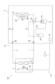
- FIG. 1 is a diagram showing an example of an overall configuration of a refrigeration cycle device 100.
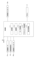
- FIG. FIG. 2 is a block diagram of a control unit 70. Mollier diagram of R454C.
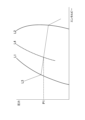
- FIG. 2 is a vapor-liquid equilibrium diagram of a mixed refrigerant of R32 and R1234yf.
- FIG. 1 is a diagram showing the relationship between the R32 content and temperature glide for a mixed refrigerant of R32 and R1234yf.
- FIG. 1 is a diagram showing the relationship between refrigerant quality and the R32 content of the circulating refrigerant when R454C is used.
- FIG. 13 is a diagram for explaining a decrease in temperature glide.
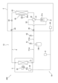
- FIG. 1 is a diagram showing an example of the overall configuration of a refrigeration cycle device 200 that is a testing machine for measuring the composition of a circulating refrigerant.
- the refrigeration cycle apparatus 100 is an air-conditioning apparatus that performs cooling operation and heating operation in a predetermined space to be air-conditioned by using a vapor compression refrigeration cycle.
- the refrigeration cycle device 100 mainly comprises a heat source unit 2, a utilization unit 3, a liquid side refrigerant connection pipe 6, a gas side refrigerant connection pipe 7, a remote control 8, and a control unit 70.
- the heat source unit 2 and the utilization unit 3 are connected via the liquid side refrigerant connection pipe 6 and the gas side refrigerant connection pipe 7 to form a main refrigerant circuit 10 in which the refrigerant circulates.
- the refrigeration cycle device 100 performs a vapor compression refrigeration cycle in which the refrigerant sealed in the main refrigerant circuit 10 is compressed, condensed, decompressed, evaporated, and then compressed again.
- the refrigeration cycle device 100 may include multiple utilization units 3. In this case, multiple utilization units 3 are connected in parallel to one heat source unit 2 to form a main refrigerant circuit 10.
- the refrigerant sealed in the main refrigerant circuit 10 is a non-azeotropic refrigerant mixture.
- a non-azeotropic refrigerant mixture is a mixture of multiple types of refrigerants with different boiling points.
- the heat source unit 2 is installed outdoors, such as outside a building having a space to be air-conditioned. As shown in Fig. 1, the heat source unit 2 mainly includes a compressor 21, a four-way switching valve 22, a heat source side heat exchanger 23, a heat source side fan 24, a heat source side expansion valve 25, an accumulator 26, a liquid side shutoff valve 28, and a gas side shutoff valve 29.
- Compressor 21 is a device that compresses low-pressure refrigerant in the refrigeration cycle until it becomes high pressure.
- Compressor 21 has a sealed structure in which a variable-volume compression element (not shown), such as a rotary or scroll type, is rotated by compressor motor 21a.
- the operating frequency (the rotation speed of compressor 21) of compressor motor 21a can be controlled by an inverter.
- the four-way switching valve 22 switches between a cooling operation connection state and a heating operation connection state by switching the connection state of the main refrigerant circuit 10.
- the cooling operation connection state (dotted line state in FIG. 1)
- the discharge side of the compressor 21 is connected to the gas side of the heat source side heat exchanger 23, and the suction side of the compressor 21 is connected to the gas side stop valve 29.
- the heating operation connection state (solid line state in FIG. 1)
- the discharge side of the compressor 21 is connected to the gas side stop valve 29, and the suction side of the compressor 21 is connected to the gas side of the heat source side heat exchanger 23.
- One of the connection ports of the four-way switching valve 22 is connected to the discharge side of the compressor 21 via the first piping 51.
- the heat source side heat exchanger 23 functions as a radiator (condenser) for high-pressure refrigerant in the refrigeration cycle during cooling operation, and as a heat sink (evaporator) for low-pressure refrigerant in the refrigeration cycle during heating operation.
- the heat source side fan 24 supplies air from outside the space to be air-conditioned (such as outside air) to the heat source side heat exchanger 23 in the heat source unit 2, exchanges heat with the refrigerant in the heat source side heat exchanger 23, and then generates an air flow for discharging the air to the outside of the heat source unit 2.
- the heat source side fan 24 is driven to rotate by the heat source side fan motor 24a.
- the heat source side expansion valve 25 is a throttling mechanism that has the function of reducing the pressure of the refrigerant.
- the heat source side expansion valve 25 is provided between the liquid side of the heat source side heat exchanger 23 and the liquid side shutoff valve 28.
- the heat source side expansion valve 25 is an electric expansion valve whose opening can be adjusted by control of the control unit 70.
- the accumulator 26 is provided between the suction side of the compressor 21 and one of the connection ports of the four-way switching valve 22. In the main refrigerant circuit 10 in the heating operation connection state, the accumulator 26 is provided between the compressor 21 and the heat source side heat exchanger 23. Inside the accumulator 26, an end of the second pipe 52 connected to the suction side of the compressor 21 and an end of the third pipe 53 connected to one of the connection ports of the four-way switching valve 22 are arranged. The second pipe 52 and the third pipe 53 are connected to each other via the accumulator 26.
- the accumulator 26 is a refrigerant container capable of temporarily storing excess refrigerant in the main refrigerant circuit 10 as liquid refrigerant.
- the refrigerant circulating in the main refrigerant circuit 10 flows through the third pipe 53 and into the inside of the accumulator 26.
- the refrigerant stored inside the accumulator 26 flows through the second pipe 52 and out of the accumulator 26.
- the liquid side shutoff valve 28 is a manual valve located at the connection between the heat source unit 2 and the liquid side refrigerant connection pipe 6.
- the gas side shutoff valve 29 is a manual valve located at the connection between the heat source unit 2 and the gas side refrigerant connection pipe 7.
- the heat source unit 2 has a heat source unit control unit 20 that controls the operation of each component that constitutes the heat source unit 2.
- the heat source unit control unit 20 constitutes the control unit 70.
- the heat source unit control unit 20 is, for example, a microcomputer including a CPU and memory.
- the heat source unit control unit 20 is connected to the utilization unit control unit 30 of the utilization unit 3 via a communication line, and transmits and receives control signals, etc.
- the utilization unit 3 is installed on the wall, ceiling, etc. of a room, etc., which is a space to be air-conditioned. As shown in FIG.
- the user-side heat exchanger 31 functions as a heat absorber (evaporator) for low-pressure refrigerant in the refrigeration cycle during cooling operation, and as a heat radiator (condenser) for high-pressure refrigerant in the refrigeration cycle during heating operation.
- the piping extending from the liquid side of the user-side heat exchanger 31 is connected to the liquid-side refrigerant connection piping 6.
- the piping extending from the gas side of the user-side heat exchanger 31 is connected to the gas-side refrigerant connection piping 7.
- the compressor 21, heat-source-side heat exchanger 23, heat-source-side expansion valve 25, and user-side heat exchanger 31 are connected in a ring shape to the main refrigerant circuit 10.
- the utilization side fan 32 supplies air from the space to be air-conditioned to the utilization side heat exchanger 31 in the utilization unit 3, exchanges heat with the refrigerant in the utilization side heat exchanger 31, and then generates an air flow for discharging the air into the space to be air-conditioned.
- the utilization side fan 32 is driven to rotate by the utilization side fan motor 32a.
- the utilization unit 3 has a utilization unit control unit 30 that controls the operation of each component that constitutes the utilization unit 3.
- the utilization unit control unit 30 constitutes the control unit 70.
- the utilization unit control unit 30 is, for example, a microcomputer that includes a CPU, memory, etc.
- the utilization unit control unit 30 is connected to the heat source unit control unit 20 of the heat source unit 2 via a communication line, and transmits and receives control signals, etc.
- the remote control 8 is placed in the space to be air-conditioned or in a specific space in a building having the space to be air-conditioned.
- the remote control 8 functions as an input device for a user of the refrigeration cycle apparatus 100 to input various instructions to the refrigeration cycle apparatus 100. For example, the user operates the remote control 8 to switch the operation state (heating operation or cooling operation) of the refrigeration cycle apparatus 100 or adjust the set temperature of the space to be air-conditioned.
- the remote control 8 also functions as a display device for displaying the operation state of the refrigeration cycle apparatus 100 and predetermined notification information.
- the remote control 8 is connected to the heat source unit control unit 20 and the utilization unit control unit 30 via communication lines, and transmits and receives signals to and from each other.
- Control Unit 70 In the refrigeration cycle apparatus 100, the heat source unit control section 20 and the utilization unit control section 30 are connected via a communication line to configure a control section 70, which is hardware that controls the operation of the refrigeration cycle apparatus 100.
- the control by the control section 70 is realized by the heat source unit control section 20 and the utilization unit control section 30 operating in an integrated manner.
- control unit 70 is electrically connected to the actuators included in the heat source unit 2.
- the actuators included in the heat source unit 2 are, specifically, the compressor motor 21a of the compressor 21, the heat source side expansion valve 25, and the heat source side fan motor 24a of the heat source side fan 24.
- the control unit 70 is also electrically connected to the remote control 8 and the actuators included in the utilization unit 3.
- the actuators included in the utilization unit 3 are, specifically, the utilization side fan motor 32a of the utilization side fan 32.
- the control unit 70 mainly has a memory unit 71, a communication unit 72, a mode control unit 73, an actuator control unit 74, and a display control unit 75. Each of these elements realizes a specific function of the control unit 70.
- the control unit 70 executes these functions by executing control programs stored in the ROM, RAM, flash memory, etc.
- the memory unit 71 stores predetermined information in a predetermined memory area upon request from other elements of the control unit 70.
- the predetermined information is, for example, the results of calculations performed by the control unit 70 and commands input to the remote control 8.
- the communication unit 72 functions as a communication interface for transmitting and receiving signals to and from each device connected to the control unit 70. Upon receiving a request from the actuator control unit 74, the communication unit 72 transmits a specified signal to a specified actuator. The communication unit 72 receives a signal output from the remote control 8, etc., and requests the memory unit 71 to store the signal in a specified memory area.
- the mode control unit 73 switches the operating mode of the refrigeration cycle device 100.
- the actuator control unit 74 controls the operation of each actuator included in the refrigeration cycle device 100 based on a control program. For example, the actuator control unit 74 controls the rotation speed of the compressor 21, the opening of the heat source side expansion valve 25, the rotation speed of the heat source side fan 24, and the rotation speed of the utilization side fan 32 in real time according to the set temperature, etc.
- the display control unit 75 is a functional unit that controls the operation of the remote control 8 as a display device.
- the display control unit 75 causes the remote control 8 to output predetermined information in order to notify the user of information related to the operating state and status of the refrigeration cycle device 100.
- the display control unit 75 causes the display of the remote control 8 to display information such as the operating mode and set temperature.
- the refrigeration cycle apparatus 100 which is an air-conditioning apparatus, operates in a cooling operation mode or a heating operation mode to adjust the temperature and humidity of the air in the space to be air-conditioned.
- the control unit 70 determines whether the operation mode should be the cooling operation mode or the heating operation mode, based on an instruction input by a user to the remote control 8.
- (2-1) Cooling Operation Mode the control unit 70 sets the four-way switching valve 22 to a cooling operation connection state and performs cooling operation in the space to be air-conditioned.
- the control unit 70 controls the rotation speed of the compressor 21, for example, so that the evaporation temperature of the refrigerant in the main refrigerant circuit 10 becomes a target evaporation temperature.
- the gas refrigerant discharged from the compressor 21 of the heat source unit 2 passes through the first pipe 51 and the four-way switching valve 22 and flows through the heat source side heat exchanger 23.
- the refrigerant flowing through the heat source side heat exchanger 23 releases heat or condenses by exchanging heat with outdoor air, and then flows toward the heat source side expansion valve 25.
- the control unit 70 controls the opening degree of the heat source side expansion valve 25 located between the heat source side heat exchanger 23 and the utilization side heat exchanger 31 so that conditions such as the degree of subcooling of the heat source side heat exchanger 23 and the degree of superheating of the utilization side heat exchanger 31 reaching predetermined target values are satisfied.
- the refrigerant decompressed by the heat source side expansion valve 25 passes through the liquid side shutoff valve 28 and the liquid side refrigerant connection pipe 6 to flow into the utilization unit 3 and into the utilization side heat exchanger 31.
- the refrigerant flowing through the utilization side heat exchanger 31 absorbs heat or evaporates by exchanging heat with the air in the space to be air-conditioned, then flows through the gas side refrigerant connection pipe 7 and flows into the heat source unit 2 from the gas side shutoff valve 29.
- the refrigerant that flows into the heat source unit 2 passes through the four-way switching valve 22, the third pipe 53, the accumulator 26, and the second pipe 52, and is sucked back into the compressor 21.
- the liquid refrigerant that did not evaporate completely in the utilization side heat exchanger 31 is stored as surplus refrigerant.
- the control unit 70 sets the four-way switching valve 22 to a heating operation connection state and performs heating operation in the space to be air-conditioned.
- the control unit 70 controls the rotation speed of the compressor 21, for example, so that the condensing temperature of the refrigerant in the main refrigerant circuit 10 becomes a target condensing temperature.
- the gas refrigerant discharged from the compressor 21 of the heat source unit 2 passes through the first pipe 51, the four-way switching valve 22, the gas side shutoff valve 29, and the gas side refrigerant connection pipe 7 to flow into the utilization unit 3 and into the utilization side heat exchanger 31.
- the refrigerant flowing through the utilization side heat exchanger 31 releases heat or condenses by exchanging heat with the air in the space to be air-conditioned, then flows through the liquid side refrigerant connection pipe 6 and flows into the heat source unit 2 from the liquid side shutoff valve 28.
- the refrigerant that flows into the heat source unit 2 is depressurized by the heat source side expansion valve 25.
- the control unit 70 controls the opening degree of the heat source side expansion valve 25 located between the utilization side heat exchanger 31 and the heat source side heat exchanger 23 so that conditions such as the degree of subcooling of the utilization side heat exchanger 31 and the degree of superheat of the heat source side heat exchanger 23 reaching predetermined target values are satisfied.
- the refrigerant decompressed by the heat source side expansion valve 25 flows through the heat source side heat exchanger 23.
- the refrigerant flowing through the heat source side heat exchanger 23 absorbs heat or evaporates by exchanging heat with outdoor air, and then passes through the four-way switching valve 22, the third pipe 53, the accumulator 26, and the second pipe 52 before being sucked back into the compressor 21.
- liquid refrigerant that did not evaporate completely in the heat source side heat exchanger 23 is stored as surplus refrigerant.
- the circulating refrigerant amount and the stagnant refrigerant amount are defined as follows.
- the circulating refrigerant amount is the weight of the circulating refrigerant, which is the refrigerant circulating through the main refrigerant circuit 10 during operation of the refrigeration cycle device 100.
- the stagnant refrigerant amount is the weight of the stagnant refrigerant, which is the liquid refrigerant stored in the accumulator 26 during operation of the refrigeration cycle device 100.
- the stagnant refrigerant does not circulate through the main refrigerant circuit 10 during operation of the refrigeration cycle device 100.
- the gas refrigerant in the accumulator 26 is a part of the circulating refrigerant and has the same composition as the circulating refrigerant.
- the temperature of the gas refrigerant in the accumulator 26 is the same as the temperature of the stagnant refrigerant. For example, when the temperature of the stagnant refrigerant is ⁇ 40° C., refrigerant at ⁇ 40° C. flows into the accumulator 26, and gas refrigerant at ⁇ 40° C. flows out of the accumulator 26. The temperature of the stagnant refrigerant is the same as the temperature of the gas outside the accumulator 26.
- the space in the main refrigerant circuit 10 in which the refrigerant is sealed is regarded as a single container, and this container is called the refrigerant circuit container.
- the charged refrigerant amount W3 is a value that can be measured when the main refrigerant circuit 10 is filled with refrigerant.
- the retained refrigerant amount W2 is, for example, the product of the effective volume of the accumulator 26 and the saturated liquid density of the refrigerant at the pressure of the refrigerant sucked into the compressor 21.
- the retained refrigerant amount W2 may also be calculated based on the height of the liquid level of the liquid refrigerant stored in the accumulator 26. The height of the liquid level of the liquid refrigerant is measured, for example, using a liquid level gauge attached to the accumulator 26.
- the weight ratio of the gas refrigerant in the refrigerant circuit container is called the refrigerant quality.
- the refrigerant quality Q is expressed by the following formula (II) or formula (III).
- Q W1 / (W1 + W2) (II)
- Q (W3 - W2) / W3 (III)
- the range of the refrigerant quality Q is 0 or more and 1 or less.
- the refrigerant quality exceeds a predetermined value that is determined according to the type of refrigerant sealed in the main refrigerant circuit 10. Specifically, the operation of the refrigeration cycle device 100 is controlled and the main refrigerant circuit 10 is designed so that the refrigerant quality exceeds the predetermined value.
- control unit 70 controls a parameter related to the wetness of the mixed refrigerant at the inlet of the accumulator 26 so that the refrigerant quality exceeds a predetermined value.
- control unit 70 adjusts the opening of the heat source side expansion valve 25 and the rotation speed of the heat source side fan 24 so that the refrigerant quality exceeds the predetermined value.
- the effective volume of the accumulator 26 is designed to be equal to or less than a predetermined value so that the refrigerant quality exceeds the predetermined value.
- the base composition is the composition of the non-azeotropic refrigerant mixture when it is filled into the main refrigerant circuit 10.
- the deviation between the circulating refrigerant composition and the base composition will be explained using Figures 3 and 4.
- the mixed refrigerant filled into the main refrigerant circuit 10 is assumed to be R454C.
- R454C contains 21.5 mass% R32 and 78.5 mass% R1234yf. Therefore, the base composition of the mixed refrigerant filled into the main refrigerant circuit 10 consists of 21.5 mass% R32 and 78.5 mass% R1234yf.
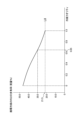
- Figure 3 is a Mollier diagram showing the saturated liquid line L1 and dry saturated vapor line L2 of R454C.
- Solid line L3 is the -40°C isotherm of R454C.
- Dotted line L4 represents the state of R454C at a specified refrigerant quality.
- Pressure P1 at the intersection of solid line L3 and dotted line L4 is the pressure of R454C at -40°C for a specified refrigerant quality.
- Figure 4 is a gas-liquid equilibrium diagram of a mixed refrigerant of R32 and R1234yf at pressure P1 in Figure 3.
- the horizontal axis of Figure 4 represents the content of R32 in the mixed refrigerant (0 mass% to 100 mass%).
- the vertical axis of Figure 4 represents the temperature of the mixed refrigerant.
- Figure 4 also shows boiling point curve L5 and dew point curve L6.
- the region lower than the boiling point curve L5 is the liquid phase.
- the region higher than the dew point curve L6 is the gas phase.
- the region between the boiling point curve L5 and the dew point curve L6 is the gas-liquid mixed phase.
- a mixed refrigerant with a base composition and an R32 content of 21.5% by mass is in a gas-liquid two-phase state at a temperature of -40°C.
- the R32 content S1 at the intersection of line L7 at -40°C and boiling point curve L5 is the R32 content of the stagnant refrigerant.
- the R32 content S2 at the intersection of line L7 at -40°C and dew point curve L6 is the R32 content of the circulating refrigerant.
- the refrigerant quality is limited to a specified range so that the difference between the R32 content S2 of the circulating refrigerant and the R32 content (21.5% by mass) of the mixed refrigerant with the base composition is equal to or less than a specified value.
- the horizontal axis of Figure 5 represents the content (mass%) of R32 contained in the mixed refrigerant of R32 and R1234yf.
- the vertical axis of Figure 5 represents the temperature glide of the mixed refrigerant. The temperature glide is the difference between the saturated gas temperature of the refrigerant and the saturated liquid temperature of the refrigerant.
- the saturated gas temperature of the refrigerant is assumed to be the condensation temperature of the refrigerant.
- the horizontal axis of Figure 6 represents the refrigerant quality of the refrigerant sealed in the main refrigerant circuit 10.
- the vertical axis of Figure 6 represents the content (mass%) of R32 contained in the circulating refrigerant. In Figure 6, the content (21.5 mass%) of R32 in the mixed refrigerant of the base composition is shown by line L8.
- the boiling point of R1234yf is higher than that of R32. Therefore, the content of R1234yf contained in the stagnant refrigerant tends to be higher than the content of R1234yf contained in the circulating refrigerant.
- the content of R32 contained in the circulating refrigerant also tends to be higher than the content of R32 contained in the stagnant refrigerant. Therefore, the lower the refrigerant quality, the greater the amount of stagnant refrigerant, and the greater the weight of R1234yf contained in the stagnant refrigerant, so the weight of R1234yf contained in the circulating refrigerant becomes smaller. Therefore, as shown in FIG.
- the refrigerant quality range is set so that the drop in temperature glide is 1 K or less.
- the temperature glide is 7.7 K.
- the R32 content of the mixed refrigerant is 30.0 mass%.
- the refrigerant quality is 0.65. Therefore, when the refrigerant quality is greater than 0.65, the R32 content of the circulating refrigerant is 21.5 mass% to 30.0 mass%, and the temperature glide is 6.7 K to 7.7 K.
- the refrigerant quality is set to exceed 0.65. This keeps the temperature glide drop below 1K, and suppresses the deviation between the circulating refrigerant composition and the base composition. In this way, the range of refrigerant quality is determined based on the temperature glide drop. Next, the temperature glide drop will be explained using Figure 7.
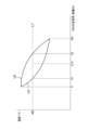
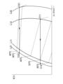
- FIG. 7 shows a Mollier diagram of a mixed refrigerant of R32 and R1234yf.
- the mixed refrigerant has a first composition or a second composition.
- the mixed refrigerant having the first composition contains 21.5 mass% R32 and 78.5 mass% R1234yf.
- the mixed refrigerant having the second composition contains 60.0 mass% R32 and 40.0 mass% R1234yf.
- FIG. 7 shows the saturated liquid line L11 and dry saturated vapor line L12 of the mixed refrigerant of the first composition, and the saturated liquid line L21 and dry saturated vapor line L22 of the mixed refrigerant of the second composition.
- FIG. 7 shows the isotherms of the mixed refrigerant of the first composition at 40°C, 33°C, and 30°C, and the isotherms of the mixed refrigerant of the second composition at 40°C and 38°C.
- the first composition is the composition of R454C, which is a mixed refrigerant sealed in the main refrigerant circuit 10.
- the first composition is a base composition.
- the second composition is an example of the composition of the circulating refrigerant when liquid refrigerant is stored in the accumulator 26 during operation of the refrigeration cycle device 100.
- the weight of R1234yf contained in the circulating refrigerant decreases as described above, and the composition of the circulating refrigerant gradually changes from the first composition to the second composition.
- FIG. 7 shows the condensation process C11-C12 of the circulating refrigerant of the first composition and the condensation process C21-C22 of the circulating refrigerant of the second composition.
- the condensation temperatures of the circulating refrigerant of the first composition and the second composition are 40°C.
- the saturated liquid temperature T1 of the circulating refrigerant of the first composition is 33°C.
- the saturated liquid temperature T3 of the circulating refrigerant of the second composition after the composition of the circulating refrigerant changes from the first composition to the second composition is 38°C.
- the temperature glide of the circulating refrigerant of the first composition is 7°C.
- the temperature glide of the circulating refrigerant of the second composition is 2°C. Therefore, when the composition of the circulating refrigerant changes from the first composition to the second composition, the temperature glide decreases by 5°C.
- the temperature glide decrease is equivalent to the value obtained by subtracting the saturated liquid temperature T1 of the circulating refrigerant of the first composition from the saturated liquid temperature T3 of the circulating refrigerant of the second composition.
- the saturated liquid temperature T3 of the circulating refrigerant with the second composition is 38°C, so if the temperature of the circulating refrigerant at the outlet of the condenser is controlled to be 30°C, the degree of subcooling will be 8°C. Therefore, if the composition of the circulating refrigerant changes from the first composition to the second composition, the refrigeration cycle device 100 will be operated with a degree of subcooling that is 5°C higher, which may result in a decrease in the performance of the condenser. Therefore, in order to minimize the increase in the degree of subcooling even if the composition of the circulating refrigerant changes, it is preferable that the temperature glide decrease is as small as possible. In this embodiment, the maximum allowable amount of temperature glide decrease is set to 1K, taking into account the variation in the measurement value of the thermistor used to measure the temperature of the circulating refrigerant.
- liquid refrigerant that has not been completely evaporated in the evaporator is stored as excess refrigerant in the accumulator 26.
- the refrigerant sealed in the main refrigerant circuit 10 is a non-azeotropic refrigerant mixture, which is a mixture of a low-boiling-point refrigerant and a high-boiling-point refrigerant.
- the boiling point of the high-boiling-point refrigerant is higher than that of the low-boiling-point refrigerant.
- the stagnant refrigerant which is the liquid refrigerant stored in the accumulator 26 has a higher content of high-boiling-point refrigerant than the circulating refrigerant circulating through the main refrigerant circuit 10.
- the stagnant refrigerant is gradually stored in the accumulator 26, the content of high-boiling-point refrigerant in the circulating refrigerant decreases, and the composition of the circulating refrigerant may deviate from the base composition.
- the amount of liquid refrigerant stored in the accumulator 26 is limited according to the type and amount of refrigerant sealed in the main refrigerant circuit 10. Specifically, the refrigeration cycle device 100 is controlled so that the refrigerant quality, which is set according to the type of refrigerant, exceeds a predetermined value.
- the higher the refrigerant quality the less the amount of stagnant refrigerant and the more the amount of circulating refrigerant. Therefore, the higher the refrigerant quality, the more the composition of the circulating refrigerant is prevented from deviating from the base composition. If the composition of the circulating refrigerant deviates from the base composition, there is a risk that the heat exchange performance and controllability of the refrigeration cycle device 100 will decrease. Therefore, the refrigeration cycle device 100 can prevent a decrease in heat exchange performance and controllability.
- the range of refrigerant quality is set so that the amount of change in temperature glide when the composition of the circulating refrigerant deviates from the base composition is equal to or less than a predetermined value. Specifically, the range of refrigerant quality is set so that the amount of decrease in temperature glide is equal to or less than 1 K. For the reasons described above, the greater the amount of decrease in temperature glide, the greater the risk of deterioration in the performance of the condenser. Therefore, the refrigeration cycle apparatus 100 can suppress the deterioration in performance caused by the change in the composition of the circulating refrigerant.
- a non-azeotropic refrigerant mixture is sealed in the main refrigerant circuit 10.
- a refrigerant such as R1123 contained in the non-azeotropic refrigerant mixture When a refrigerant such as R1123 contained in the non-azeotropic refrigerant mixture generates radicals, it may change into another compound through a disproportionation reaction.
- the disproportionation reaction is accompanied by the release of a large amount of heat. Therefore, the reliability of the refrigeration cycle apparatus 100 may be reduced if the refrigerant contained in the circulating refrigerant causes a disproportionation reaction.
- the refrigeration cycle device 100 prevents the composition of the circulating refrigerant from deviating from the base composition. This prevents an increase in the content of refrigerants in the circulating refrigerant that are prone to causing disproportionation reactions. Therefore, the refrigeration cycle device 100 can prevent a decrease in reliability caused by disproportionation reactions of the refrigerant.
- Example As shown in Fig. 6, in the refrigeration cycle apparatus 100, the composition of the circulating refrigerant changes depending on the refrigerant quality.
- an experiment was conducted to compare the actual measured value of the composition of the circulating refrigerant with the predicted value of the composition of the circulating refrigerant, as described below.
- the actual measured value was obtained by measuring the composition of the circulating refrigerant when the refrigerant quality was a predetermined value.
- the predicted value was obtained by calculating the change in composition based on the vapor-liquid equilibrium state of the refrigerant stored in the accumulator.
- a refrigeration cycle apparatus 200 which is a testing machine for measuring the actual values of the composition of the circulating refrigerant, has a configuration similar to that of the refrigeration cycle apparatus 100 shown in Fig. 1.
- the accumulator 126 is attached to the gas side refrigerant communication pipe 7 outside the heat source unit 2, not inside the heat source unit 2.
- the second pipe 52 connected to the suction side of the compressor 21 is directly connected to one of the connection ports of the four-way switching valve 22.
- the accumulator 126 is attached with a liquid level gauge for measuring the volume of the liquid refrigerant stored in the accumulator 126.
- the gas side refrigerant connection pipe 7 is divided into a first connection pipe 7a and a second connection pipe 7b by the accumulator 126.
- the first connection pipe 7a connects the gas side of the user side heat exchanger 31 to the accumulator 126.
- the second connection pipe 7b connects the accumulator 126 to the gas side shutoff valve 29.
- a first sampling valve 61 and a second sampling valve 62 are attached to the second connection pipe 7b.
- the first sampling valve 61 is attached near the accumulator 126.
- the second sampling valve 62 is attached near the gas side shutoff valve 29.
- the refrigeration cycle device 200 which is the test machine, is an air conditioner with a cooling capacity of 4.0 kW.
- the refrigeration cycle device 200 is operated in a cooling operation mode.
- the length of the liquid side refrigerant communication pipe 6 is 5.0 m.
- the outer diameter of the liquid side refrigerant communication pipe 6 is 6.4 mm.
- the length of the gas side refrigerant communication pipe 7 is 5.0 m.
- the outer diameter of the gas side refrigerant communication pipe 7 is 9.5 mm.
- the non-azeotropic refrigerant mixture filled in the main refrigerant circuit 10 of the refrigeration cycle device 200 is R454C.
- R454C contains 21.5% by mass of R32 and 78.5% by mass of R1234yf.
- a predetermined amount of additional refrigerant is charged so that liquid refrigerant accumulates in the accumulator 126.
- a parameter related to the wetness of the circulating refrigerant is manually controlled so that liquid refrigerant is stored in the accumulator 126.
- the gas refrigerant in the accumulator 126 and the circulating refrigerant were sampled, and the compositions of the refrigerants were measured by gas chromatography to obtain actual values of the composition of the circulating refrigerant.
- the gas refrigerant in the accumulator 126 was sampled from the first sampling valve 61.
- the circulating refrigerant was sampled from the second sampling valve 62.
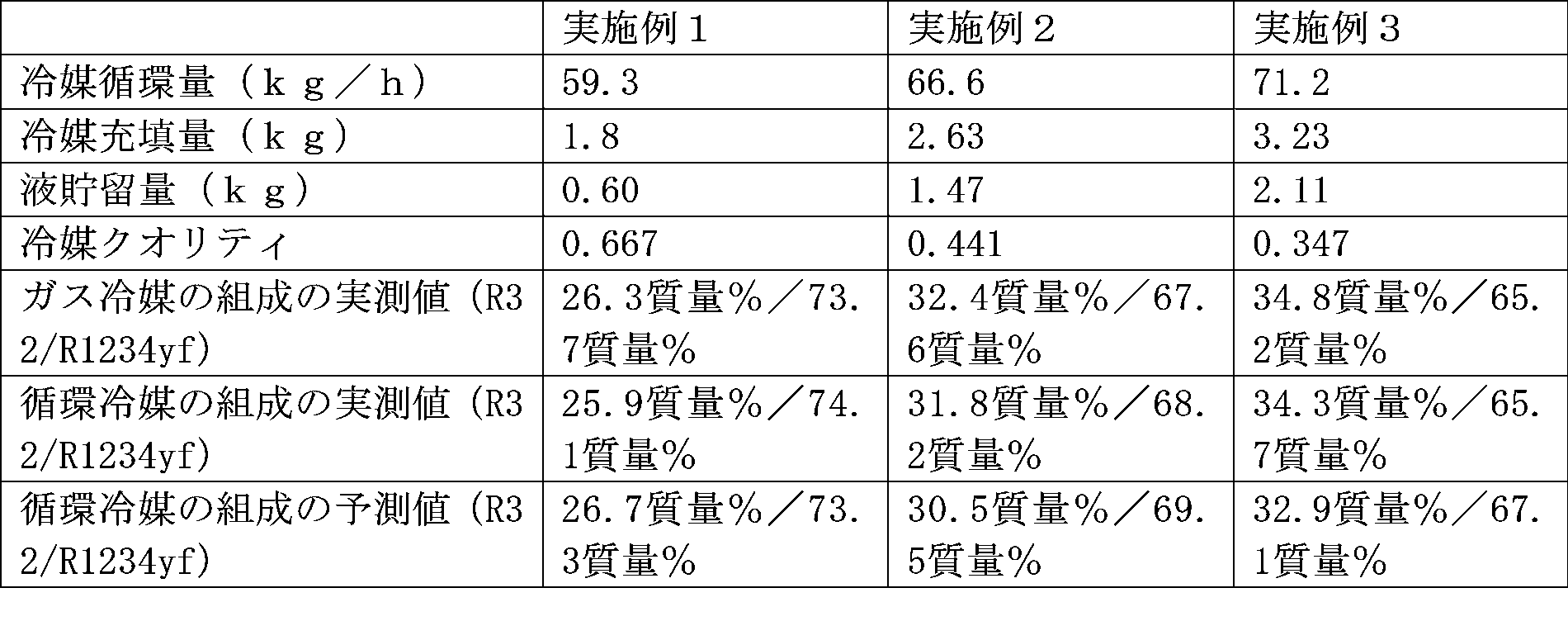
- the refrigerant circulation amount is the weight of refrigerant circulating through the main refrigerant circuit 10 per hour.
- the refrigerant charge amount is the weight of refrigerant charged in the main refrigerant circuit 10 after additional refrigerant is charged.
- the liquid storage amount is the weight of liquid refrigerant stored in the accumulator 126.
- the refrigerant qualities of Examples 1 to 3 are different from each other.
- the measured and predicted composition values are listed in the order of R32 content (mass%) and R1234yf content (mass%).
- the mixed refrigerant filled in the main refrigerant circuit 10 is R454C.
- R454C contains 21.5 mass% R32 and 78.5 mass% R1234yf.
- the content of R32 is limited to 30.0 mass% or less so that the temperature glide drop amount when the composition of the circulating refrigerant deviates from the base composition is 1 K or less.
- the refrigerant quality is set to be higher than 0.65.
- the first mixed refrigerant contains R1132(E) and R1234yf.
- the base composition of the first mixed refrigerant is 23.0 mass% R1132(E) and 77.0 mass% R1234yf.
- the temperature glide is 7.0 K.
- the temperature glide decreases by 1 K from 7.0 K to 6.0 K, the content of R1132(E) in the first mixed refrigerant is 45.0 mass%.
- the content of R1132(E) is limited to 45.0 mass% or less so that the temperature glide drop when the circulating refrigerant composition deviates from the base composition is 1 K or less. Therefore, when using the first mixed refrigerant, the refrigerant quality is set to be greater than 0.15.
- the second mixed refrigerant contains R1132(E), R1234yf, and R32.
- the base composition of the second mixed refrigerant is 22.0 mass% R1132(E), 56.0 mass% R1234yf, and 22.0 mass% R32.
- the temperature glide is 5.3 K.
- the content of R1132(E) in the second mixed refrigerant is 32.0 mass%.
- the content of R1132(E) is limited to 32.0 mass% or less so that the temperature glide drop when the circulating refrigerant composition deviates from the base composition is 1 K or less. Therefore, when using the second mixed refrigerant, the refrigerant quality is set to be greater than 0.22.
- the third mixed refrigerant contains R1123 and R1234yf.
- the base composition of the third mixed refrigerant is 34.0 mass% R1123 and 66.0 mass% R1234yf.
- the temperature glide is 8.0 K.
- the temperature glide decreases by 1 K from 8.0 K to 7.0 K, the content of R1123 in the third mixed refrigerant is 61.0 mass%.
- the R1123 content is limited to 61.0 mass% or less so that the temperature glide drop when the circulating refrigerant composition deviates from the base composition is 1 K or less. Therefore, when using the third mixed refrigerant, the refrigerant quality is set to be greater than 0.12.
Landscapes
- Engineering & Computer Science (AREA)
- Chemical & Material Sciences (AREA)
- Physics & Mathematics (AREA)
- Thermal Sciences (AREA)
- Mechanical Engineering (AREA)
- General Engineering & Computer Science (AREA)
- Chemical Kinetics & Catalysis (AREA)
- Combustion & Propulsion (AREA)
- Materials Engineering (AREA)
- Organic Chemistry (AREA)
- Analytical Chemistry (AREA)
- Power Engineering (AREA)
- Compression-Type Refrigeration Machines With Reversible Cycles (AREA)
Abstract
Description
冷凍サイクル装置100は、蒸気圧縮式の冷凍サイクルによって、所定の空調対象空間の冷房運転及び暖房運転を行う空気調和装置である。
熱源ユニット2は、空調対象空間を有する建物の外部等の屋外に設置される。図1に示されるように、熱源ユニット2は、主として、圧縮機21と、四路切換弁22と、熱源側熱交換器23と、熱源側ファン24と、熱源側膨張弁25と、アキュームレータ26と、液側閉鎖弁28と、ガス側閉鎖弁29と、を有する。
利用ユニット3は、空調対象空間である部屋等の壁及び天井等に設置される。図1に示されるように、利用ユニット3は、主として、利用側熱交換器31と、利用側ファン32と、を有する。
リモコン8は、空調対象空間、又は、空調対象空間を有する建物内の特定の空間に配置される。リモコン8は、冷凍サイクル装置100のユーザが、冷凍サイクル装置100に各種指示を入力するための入力装置として機能する。ユーザは、例えば、リモコン8を操作して、冷凍サイクル装置100の運転状態(暖房運転又は冷房運転)を切り換えたり、空調対象空間の設定温度を調整したりする。リモコン8は、冷凍サイクル装置100の運転状態、及び、所定の報知情報を表示するための表示装置としても機能する。リモコン8は、熱源ユニット制御部20及び利用ユニット制御部30と通信線を介して接続され、相互に信号の送受信を行う。
冷凍サイクル装置100では、熱源ユニット制御部20と利用ユニット制御部30とが通信線を介して接続されることで、冷凍サイクル装置100の動作を制御するハードウェアである制御部70が構成される。制御部70による制御は、熱源ユニット制御部20及び利用ユニット制御部30が一体的に動作することにより実現される。
空気調和装置である冷凍サイクル装置100は、冷房運転モード又は暖房運転モードで運転して、空調対象空間の空気の温度及び湿度を調整する。制御部70は、ユーザによってリモコン8に入力された指示に基づいて、冷房運転モード及び暖房運転モードのいずれの運転モードで運転すべきかを判断する。
冷房運転モードでは、制御部70は、四路切換弁22を冷房運転接続状態にして、空調対象空間における冷房運転を実行する。冷房運転モードでは、制御部70は、例えば、メイン冷媒回路10における冷媒の蒸発温度が目標蒸発温度になるように、圧縮機21の回転数を制御する。
暖房運転モードでは、制御部70は、四路切換弁22を暖房運転接続状態にして、空調対象空間における暖房運転を実行する。暖房運転モードでは、制御部70は、例えば、メイン冷媒回路10における冷媒の凝縮温度が目標凝縮温度になるように、圧縮機21の回転数を制御する。
循環冷媒量及び滞留冷媒量を次のように定義する。循環冷媒量とは、冷凍サイクル装置100の運転中にメイン冷媒回路10を循環する冷媒である循環冷媒の重量である。滞留冷媒量とは、冷凍サイクル装置100の運転中にアキュームレータ26内に貯留される液冷媒である滞留冷媒の重量である。滞留冷媒は、冷凍サイクル装置100の運転中にメイン冷媒回路10を循環しない。アキュームレータ26内のガス冷媒は、循環冷媒の一部であり、循環冷媒と同じ組成を有する。アキュームレータ26内のガス冷媒の温度は、滞留冷媒の温度と同じである。例えば、滞留冷媒の温度が-40℃の場合、アキュームレータ26には-40℃の冷媒が流入し、アキュームレータ26からは-40℃のガス冷媒が流出する。滞留冷媒の温度は、アキュームレータ26の外部の気体の温度と同じである。
W3=W1+W2 ・・・(I)
Q=W1/(W1+W2) ・・・(II)
Q=(W3-W2)/W3 ・・・(III)
(4-1)
メイン冷媒回路10を循環する冷媒のうち、蒸発器において蒸発しきれなかった液冷媒は、余剰冷媒としてアキュームレータ26内に貯留される。メイン冷媒回路10内に封入される冷媒は、低沸点冷媒と高沸点冷媒との混合物である非共沸混合冷媒である。高沸点冷媒の沸点は、低沸点冷媒の沸点よりも高い。そのため、アキュームレータ26内に貯留される液冷媒である滞留冷媒は、メイン冷媒回路10を循環する循環冷媒よりも、高沸点冷媒の含有率が高い。その結果、アキュームレータ26内に滞留冷媒が徐々に貯留されると、循環冷媒の高沸点冷媒の含有率が低下して、循環冷媒の組成がベース組成から乖離するおそれがある。
冷凍サイクル装置100では、循環冷媒の組成がベース組成から乖離した場合の温度グライドの変化量が所定値以下となるように、冷媒クオリティの範囲が設定される。具体的には、温度グライドの低下量が1K以下となるように、冷媒クオリティの範囲が設定される。上述した理由により、温度グライドの低下量が大きいほど、凝縮器の性能が低下するおそれがある。そのため、冷凍サイクル装置100は、循環冷媒の組成の変化に起因する性能低下を抑制することができる。
冷凍サイクル装置100では、メイン冷媒回路10内に非共沸混合冷媒が封入される。非共沸混合冷媒に含まれるR1123等の冷媒が、ラジカルを生成する場合、不均化反応により別の化合物に変化する場合がある。不均化反応は多量の熱放出を伴う。そのため、循環冷媒に含まれる冷媒が不均化反応を引き起こすことで、冷凍サイクル装置100の信頼性が低下するおそれがある。
図6に示されるように、冷凍サイクル装置100において、循環冷媒の組成は、冷媒クオリティに応じて変化する。循環冷媒の組成の変化量の確からしさを検証するために、次に説明するように、循環冷媒の組成の実測値と、循環冷媒の組成の予測値とを比較する実験を行った。実測値は、冷媒クオリティが所定の値である場合における、循環冷媒の組成を計測して得られた。予測値は、アキュームレータに貯留される冷媒の気液平衡状態に基づく組成の変化を算出して得られた。
図8に示されるように、循環冷媒の組成の実測値を測定するための試験機である冷凍サイクル装置200は、図1に示される冷凍サイクル装置100と類似する構成を有する。ただし、冷凍サイクル装置200では、アキュームレータ126は、熱源ユニット2の内部ではなく、熱源ユニット2の外部のガス側冷媒連絡配管7に取り付けられている。熱源ユニット2の内部では、圧縮機21の吸入側に接続される第2配管52は、四路切換弁22の接続ポートの1つに直接接続される。アキュームレータ126には、アキュームレータ126に貯留される液冷媒の容量を計測するための液面計が取り付けられている。
試験機である冷凍サイクル装置200は、冷房能力4.0kWの空気調和装置である。冷凍サイクル装置200は、冷房運転モードで運転される。液側冷媒連絡配管6の長さは、5.0mである。液側冷媒連絡配管6の外径は、6.4mmである。ガス側冷媒連絡配管7の長さは、5.0mである。ガス側冷媒連絡配管7の外径は、9.5mmである。
アキュームレータ126内のガス冷媒、及び、循環冷媒をサンプリングして、ガスクロマトグラフィーによって冷媒の組成を測定して、循環冷媒の組成の実測値を取得した。アキュームレータ126内のガス冷媒は、第1サンプリング弁61からサンプリングした。循環冷媒は、第2サンプリング弁62からサンプリングした。
冷媒クオリティ=(冷媒充填量-液貯留量)/冷媒充填量 ・・・(IV)
実施形態において、メイン冷媒回路10に封入される混合冷媒は、R454Cである。R454Cは、21.5質量%のR32と、78.5質量%のR1234yfと、を含む。この場合、循環冷媒の組成がベース組成から乖離した場合の温度グライドの低下量が1K以下となるように、R32の含有率が30.0質量%以下に制限される。その結果、冷媒クオリティは0.65を上回るように設定される。
第1の混合冷媒は、R1132(E)とR1234yfとを含む。第1の混合冷媒のベース組成は、23.0質量%のR1132(E)と、77.0質量%のR1234yfと、からなる。第1の混合冷媒のR1132(E)の含有率が、ベース組成の第1の混合冷媒のR1132(E)の含有率(23.0質量%)である場合の温度グライドは7.0Kである。温度グライドが7.0Kから1K低下して6.0Kとなった時における、第1の混合冷媒のR1132(E)の含有率は45.0質量%である。
第2の混合冷媒は、R1132(E)とR1234yfとR32とを含む。第2の混合冷媒のベース組成は、22.0質量%のR1132(E)と、56.0質量%のR1234yfと、22.0質量%のR32と、からなる。第2の混合冷媒のR1132(E)の含有率が、ベース組成の第2の混合冷媒のR1132(E)の含有率(22.0質量%)である場合の温度グライドは5.3Kである。温度グライドが5.3Kから1K低下して4.3Kとなった時における、第2の混合冷媒のR1132(E)の含有率は32.0質量%である。
第3の混合冷媒は、R1123とR1234yfとを含む。第3の混合冷媒のベース組成は、34.0質量%のR1123と、66.0質量%のR1234yfと、からなる。第3の混合冷媒のR1123の含有率が、ベース組成の第3の混合冷媒のR1123の含有率(34.0質量%)である場合の温度グライドは8.0Kである。温度グライドが8.0Kから1K低下して7.0Kとなった時における、第3の混合冷媒のR1123の含有率は61.0質量%である。
21 :圧縮機
23 :熱源側熱交換器(蒸発器,凝縮器)
25 :熱源側膨張弁(膨張機構)
26 :アキュームレータ
31 :利用側熱交換器(凝縮器、蒸発器)
70 :制御部
100 :冷凍サイクル装置
Claims (9)
- 圧縮機(21)と、
凝縮器(23)と、
膨張機構(25)と、
蒸発器(31)と、
アキュームレータ(26)と、
前記圧縮機、前記凝縮器、前記膨張機構、前記蒸発器、及び、前記アキュームレータが環状に接続され、混合冷媒が封入される冷媒回路(10)と、
を備え、
前記冷媒回路に封入される前記混合冷媒の量を第1量として、前記アキュームレータ内に貯留されている液冷媒の量を第2量とした場合に、前記第1量から前記第2量を引いた値を前記第1量で割った第1値は、前記混合冷媒に応じて決められる値を上回り、
前記混合冷媒は、非共沸混合冷媒である、
冷凍サイクル装置(100)。 - 前記第2量は、前記アキュームレータの有効容積と、前記圧縮機に吸入される前記混合冷媒の圧力における前記混合冷媒の飽和液体密度と、の積である、
請求項1に記載の冷凍サイクル装置。 - 前記冷媒回路に封入される前記混合冷媒は、第1の組成を有し、
前記アキュームレータ内に前記液冷媒が貯留されている場合に、前記冷媒回路を循環する前記混合冷媒は、第2の組成を有し、
T1は、前記第1の組成を有する前記混合冷媒の飽和液温度であり、
T2は、前記凝縮器の出口における、前記第1の組成を有する前記混合冷媒の温度の目標値であり、
T3は、前記凝縮器の出口における前記混合冷媒の温度がT2に制御されている場合に、前記混合冷媒の組成が前記第1の組成から前記第2の組成に変化した後における、前記第2の組成を有する前記混合冷媒の飽和液温度であり、
T3からT1を引いた第2値が1K以下となるように、前記第1値が設定される、
請求項1又は2に記載の冷凍サイクル装置。 - 前記混合冷媒は、21.5質量%のR32と、78.5質量%のR1234yfと、を含み、
前記第1値は、0.65を上回る、
請求項1から3のいずれか1項に記載の冷凍サイクル装置。 - 前記混合冷媒は、23.0質量%のR1132(E)と、77.0質量%のR1234yfと、を含み、
前記第1値は、0.15を上回る、
請求項1から3のいずれか1項に記載の冷凍サイクル装置。 - 前記混合冷媒は、22.0質量%のR1132(E)と、56.0質量%のR1234yfと、22.0質量%のR32と、を含み、
前記第1値は、0.22を上回る、
請求項1から3のいずれか1項に記載の冷凍サイクル装置。 - 前記混合冷媒は、34.0質量%のR1123と、66.0質量%のR1234yfと、を含み、
前記第1値は、0.12を上回る、
請求項1から3のいずれか1項に記載の冷凍サイクル装置。 - 前記アキュームレータの入口における前記混合冷媒の湿り度に関するパラメータを制御する制御部(70)をさらに備える、
請求項1から7のいずれか1項に記載の冷凍サイクル装置。 - 前記アキュームレータは、所定値以下の有効容積を有する、
請求項1から8のいずれか1項に記載の冷凍サイクル装置。
Priority Applications (3)
| Application Number | Priority Date | Filing Date | Title |
|---|---|---|---|
| EP23872228.4A EP4596996A4 (en) | 2022-09-28 | 2023-09-25 | REFRIGERATION CYCLE DEVICE |
| CN202380063919.2A CN119816693A (zh) | 2022-09-28 | 2023-09-25 | 冷冻循环装置 |
| US19/092,564 US20250224165A1 (en) | 2022-09-28 | 2025-03-27 | Refrigeration cycle apparatus |
Applications Claiming Priority (2)
| Application Number | Priority Date | Filing Date | Title |
|---|---|---|---|
| JP2022155366A JP7502672B2 (ja) | 2022-09-28 | 2022-09-28 | 冷凍サイクル装置 |
| JP2022-155366 | 2022-09-28 |
Related Child Applications (1)
| Application Number | Title | Priority Date | Filing Date |
|---|---|---|---|
| US19/092,564 Continuation US20250224165A1 (en) | 2022-09-28 | 2025-03-27 | Refrigeration cycle apparatus |
Publications (1)
| Publication Number | Publication Date |
|---|---|
| WO2024071003A1 true WO2024071003A1 (ja) | 2024-04-04 |
Family
ID=90477800
Family Applications (1)
| Application Number | Title | Priority Date | Filing Date |
|---|---|---|---|
| PCT/JP2023/034635 Ceased WO2024071003A1 (ja) | 2022-09-28 | 2023-09-25 | 冷凍サイクル装置 |
Country Status (5)
| Country | Link |
|---|---|
| US (1) | US20250224165A1 (ja) |
| EP (1) | EP4596996A4 (ja) |
| JP (2) | JP7502672B2 (ja) |
| CN (1) | CN119816693A (ja) |
| WO (1) | WO2024071003A1 (ja) |
Families Citing this family (3)
| Publication number | Priority date | Publication date | Assignee | Title |
|---|---|---|---|---|
| WO2025243502A1 (ja) * | 2024-05-24 | 2025-11-27 | 日立ジョンソンコントロールズ空調株式会社 | 冷凍サイクル装置 |
| WO2025243514A1 (ja) * | 2024-05-24 | 2025-11-27 | 日立ジョンソンコントロールズ空調株式会社 | 冷凍サイクルおよび空気調和装置 |
| WO2025243501A1 (ja) * | 2024-05-24 | 2025-11-27 | 日立ジョンソンコントロールズ空調株式会社 | 冷凍サイクル装置 |
Citations (4)
| Publication number | Priority date | Publication date | Assignee | Title |
|---|---|---|---|---|
| JP2002039648A (ja) * | 2000-07-25 | 2002-02-06 | Mitsubishi Electric Corp | 冷媒封入方法および空気調和機 |
| JP2002089978A (ja) * | 2000-09-11 | 2002-03-27 | Daikin Ind Ltd | ペア型の冷凍装置およびマルチ型の冷凍装置 |
| JP2004232951A (ja) * | 2003-01-30 | 2004-08-19 | Mitsubishi Electric Corp | 冷媒封入方法 |
| JP2015200431A (ja) | 2014-04-04 | 2015-11-12 | 三菱電機株式会社 | 空気調和機 |
Family Cites Families (3)
| Publication number | Priority date | Publication date | Assignee | Title |
|---|---|---|---|---|
| JPH0821667A (ja) * | 1994-07-07 | 1996-01-23 | Matsushita Refrig Co Ltd | 空気調和機 |
| US5626026A (en) * | 1994-07-21 | 1997-05-06 | Mitsubishi Denki Kabushiki Kaisha | Control-information detecting apparatus for a refrigeration air-conditioner using a non-azeotrope refrigerant |
| JPH09152199A (ja) * | 1995-11-28 | 1997-06-10 | Sanyo Electric Co Ltd | 空気調和機 |
-
2022
- 2022-09-28 JP JP2022155366A patent/JP7502672B2/ja active Active
-
2023
- 2023-09-25 EP EP23872228.4A patent/EP4596996A4/en active Pending
- 2023-09-25 WO PCT/JP2023/034635 patent/WO2024071003A1/ja not_active Ceased
- 2023-09-25 CN CN202380063919.2A patent/CN119816693A/zh active Pending
-
2024
- 2024-05-28 JP JP2024086054A patent/JP2024105724A/ja active Pending
-
2025
- 2025-03-27 US US19/092,564 patent/US20250224165A1/en active Pending
Patent Citations (4)
| Publication number | Priority date | Publication date | Assignee | Title |
|---|---|---|---|---|
| JP2002039648A (ja) * | 2000-07-25 | 2002-02-06 | Mitsubishi Electric Corp | 冷媒封入方法および空気調和機 |
| JP2002089978A (ja) * | 2000-09-11 | 2002-03-27 | Daikin Ind Ltd | ペア型の冷凍装置およびマルチ型の冷凍装置 |
| JP2004232951A (ja) * | 2003-01-30 | 2004-08-19 | Mitsubishi Electric Corp | 冷媒封入方法 |
| JP2015200431A (ja) | 2014-04-04 | 2015-11-12 | 三菱電機株式会社 | 空気調和機 |
Non-Patent Citations (1)
| Title |
|---|
| See also references of EP4596996A4 |
Also Published As
| Publication number | Publication date |
|---|---|
| EP4596996A1 (en) | 2025-08-06 |
| JP7502672B2 (ja) | 2024-06-19 |
| US20250224165A1 (en) | 2025-07-10 |
| CN119816693A (zh) | 2025-04-11 |
| JP2024049103A (ja) | 2024-04-09 |
| JP2024105724A (ja) | 2024-08-06 |
| EP4596996A4 (en) | 2026-01-07 |
Similar Documents
| Publication | Publication Date | Title |
|---|---|---|
| JP7502672B2 (ja) | 冷凍サイクル装置 | |
| CN105627649B (zh) | 冷冻循环装置 | |
| JP4864110B2 (ja) | 冷凍空調装置 | |
| JP4200532B2 (ja) | 冷凍装置 | |
| EP2752627B1 (en) | Refrigeration device | |
| JP5791716B2 (ja) | 冷凍空調装置及び冷凍空調装置の制御方法 | |
| EP3611443B1 (en) | Refrigeration cycle device | |
| CN112840164A (zh) | 空调装置、管理装置及制冷剂连通管 | |
| WO2004063644A1 (ja) | 冷凍装置及び冷凍装置の冷媒量検出方法 | |
| US12181168B2 (en) | Air conditioner and control method thereof | |
| EP3779326B1 (en) | Refrigeration cycle device | |
| AU2016279490A1 (en) | Air conditioner | |
| WO2023092889A1 (zh) | 一种多联机空调 | |
| JP6758506B2 (ja) | 空気調和装置 | |
| WO2024047954A1 (ja) | 冷凍サイクル装置および空気調和装置 | |
| US11835273B2 (en) | Refrigerant cycle apparatus | |
| JP2002295915A (ja) | 空気調和機 | |
| WO2019082331A1 (ja) | 冷凍空調装置及び制御装置 | |
| JP2002039648A (ja) | 冷媒封入方法および空気調和機 | |
| US11384949B2 (en) | Air conditioner system and control method thereof | |
| JP2024049104A (ja) | 冷凍サイクル装置 | |
| EP3882536A1 (en) | Air conditioner | |
| JP2001304699A (ja) | 冷凍装置 | |
| JP4548502B2 (ja) | 冷凍装置 | |
| WO2022029845A1 (ja) | 空気調和装置 |
Legal Events
| Date | Code | Title | Description |
|---|---|---|---|
| 121 | Ep: the epo has been informed by wipo that ep was designated in this application |
Ref document number: 23872228 Country of ref document: EP Kind code of ref document: A1 |
|
| WWE | Wipo information: entry into national phase |
Ref document number: 202380063919.2 Country of ref document: CN |
|
| WWP | Wipo information: published in national office |
Ref document number: 202380063919.2 Country of ref document: CN |
|
| WWE | Wipo information: entry into national phase |
Ref document number: 202517038058 Country of ref document: IN |
|
| WWE | Wipo information: entry into national phase |
Ref document number: 2023872228 Country of ref document: EP |
|
| NENP | Non-entry into the national phase |
Ref country code: DE |
|
| ENP | Entry into the national phase |
Ref document number: 2023872228 Country of ref document: EP Effective date: 20250428 |
|
| WWP | Wipo information: published in national office |
Ref document number: 202517038058 Country of ref document: IN |
|
| WWP | Wipo information: published in national office |
Ref document number: 2023872228 Country of ref document: EP |