WO2024071005A1 - 多孔質膜および造水方法 - Google Patents
多孔質膜および造水方法 Download PDFInfo
- Publication number
- WO2024071005A1 WO2024071005A1 PCT/JP2023/034640 JP2023034640W WO2024071005A1 WO 2024071005 A1 WO2024071005 A1 WO 2024071005A1 JP 2023034640 W JP2023034640 W JP 2023034640W WO 2024071005 A1 WO2024071005 A1 WO 2024071005A1
- Authority
- WO
- WIPO (PCT)
- Prior art keywords
- porous membrane
- membrane
- water
- reverse osmosis
- porous
- Prior art date
- Legal status (The legal status is an assumption and is not a legal conclusion. Google has not performed a legal analysis and makes no representation as to the accuracy of the status listed.)
- Ceased
Links
Images
Classifications
-
- B—PERFORMING OPERATIONS; TRANSPORTING
- B01—PHYSICAL OR CHEMICAL PROCESSES OR APPARATUS IN GENERAL
- B01D—SEPARATION
- B01D61/00—Processes of separation using semi-permeable membranes, e.g. dialysis, osmosis or ultrafiltration; Apparatus, accessories or auxiliary operations specially adapted therefor
- B01D61/02—Reverse osmosis; Hyperfiltration ; Nanofiltration
- B01D61/025—Reverse osmosis; Hyperfiltration
-
- B—PERFORMING OPERATIONS; TRANSPORTING
- B01—PHYSICAL OR CHEMICAL PROCESSES OR APPARATUS IN GENERAL
- B01D—SEPARATION
- B01D61/00—Processes of separation using semi-permeable membranes, e.g. dialysis, osmosis or ultrafiltration; Apparatus, accessories or auxiliary operations specially adapted therefor
- B01D61/14—Ultrafiltration; Microfiltration
- B01D61/145—Ultrafiltration
-
- B—PERFORMING OPERATIONS; TRANSPORTING
- B01—PHYSICAL OR CHEMICAL PROCESSES OR APPARATUS IN GENERAL
- B01D—SEPARATION
- B01D61/00—Processes of separation using semi-permeable membranes, e.g. dialysis, osmosis or ultrafiltration; Apparatus, accessories or auxiliary operations specially adapted therefor
- B01D61/58—Multistep processes
-
- B—PERFORMING OPERATIONS; TRANSPORTING
- B01—PHYSICAL OR CHEMICAL PROCESSES OR APPARATUS IN GENERAL
- B01D—SEPARATION
- B01D69/00—Semi-permeable membranes for separation processes or apparatus characterised by their form, structure or properties; Manufacturing processes specially adapted therefor
- B01D69/02—Semi-permeable membranes for separation processes or apparatus characterised by their form, structure or properties; Manufacturing processes specially adapted therefor characterised by their properties
-
- B—PERFORMING OPERATIONS; TRANSPORTING
- B01—PHYSICAL OR CHEMICAL PROCESSES OR APPARATUS IN GENERAL
- B01D—SEPARATION
- B01D71/00—Semi-permeable membranes for separation processes or apparatus characterised by the material; Manufacturing processes specially adapted therefor
- B01D71/06—Organic material
- B01D71/30—Polyalkenyl halides
- B01D71/32—Polyalkenyl halides containing fluorine atoms
- B01D71/34—Polyvinylidene fluoride
-
- C—CHEMISTRY; METALLURGY
- C02—TREATMENT OF WATER, WASTE WATER, SEWAGE, OR SLUDGE
- C02F—TREATMENT OF WATER, WASTE WATER, SEWAGE, OR SLUDGE
- C02F1/00—Treatment of water, waste water, or sewage
- C02F1/44—Treatment of water, waste water, or sewage by dialysis, osmosis or reverse osmosis
- C02F1/441—Treatment of water, waste water, or sewage by dialysis, osmosis or reverse osmosis by reverse osmosis
-
- C—CHEMISTRY; METALLURGY
- C02—TREATMENT OF WATER, WASTE WATER, SEWAGE, OR SLUDGE
- C02F—TREATMENT OF WATER, WASTE WATER, SEWAGE, OR SLUDGE
- C02F1/00—Treatment of water, waste water, or sewage
- C02F1/44—Treatment of water, waste water, or sewage by dialysis, osmosis or reverse osmosis
- C02F1/444—Treatment of water, waste water, or sewage by dialysis, osmosis or reverse osmosis by ultrafiltration or microfiltration
-
- B—PERFORMING OPERATIONS; TRANSPORTING
- B01—PHYSICAL OR CHEMICAL PROCESSES OR APPARATUS IN GENERAL
- B01D—SEPARATION
- B01D2325/00—Details relating to properties of membranes
- B01D2325/02—Details relating to pores or porosity of the membranes
-
- B—PERFORMING OPERATIONS; TRANSPORTING
- B01—PHYSICAL OR CHEMICAL PROCESSES OR APPARATUS IN GENERAL
- B01D—SEPARATION
- B01D2325/00—Details relating to properties of membranes
- B01D2325/02—Details relating to pores or porosity of the membranes
- B01D2325/0283—Pore size
-
- B—PERFORMING OPERATIONS; TRANSPORTING
- B01—PHYSICAL OR CHEMICAL PROCESSES OR APPARATUS IN GENERAL
- B01D—SEPARATION
- B01D2325/00—Details relating to properties of membranes
- B01D2325/20—Specific permeability or cut-off range
-
- B—PERFORMING OPERATIONS; TRANSPORTING
- B01—PHYSICAL OR CHEMICAL PROCESSES OR APPARATUS IN GENERAL
- B01D—SEPARATION
- B01D2325/00—Details relating to properties of membranes
- B01D2325/52—Crystallinity
-
- C—CHEMISTRY; METALLURGY
- C02—TREATMENT OF WATER, WASTE WATER, SEWAGE, OR SLUDGE
- C02F—TREATMENT OF WATER, WASTE WATER, SEWAGE, OR SLUDGE
- C02F2103/00—Nature of the water, waste water, sewage or sludge to be treated
- C02F2103/08—Seawater, e.g. for desalination
-
- Y—GENERAL TAGGING OF NEW TECHNOLOGICAL DEVELOPMENTS; GENERAL TAGGING OF CROSS-SECTIONAL TECHNOLOGIES SPANNING OVER SEVERAL SECTIONS OF THE IPC; TECHNICAL SUBJECTS COVERED BY FORMER USPC CROSS-REFERENCE ART COLLECTIONS [XRACs] AND DIGESTS
- Y02—TECHNOLOGIES OR APPLICATIONS FOR MITIGATION OR ADAPTATION AGAINST CLIMATE CHANGE
- Y02A—TECHNOLOGIES FOR ADAPTATION TO CLIMATE CHANGE
- Y02A20/00—Water conservation; Efficient water supply; Efficient water use
- Y02A20/124—Water desalination
- Y02A20/131—Reverse-osmosis
Definitions
- the present invention relates to porous membranes for use in fields such as water treatment, pharmaceutical manufacturing, food industry, and fermentation.
- porous membranes such as microfiltration membranes and ultrafiltration membranes have been used in a variety of fields, including water treatment (such as water purification or wastewater treatment), medical fields (such as blood purification), and the food industry.
- water treatment such as water purification or wastewater treatment
- medical fields such as blood purification
- food industry Recently, there has been a demand for highly fouling-resistant porous membranes that can efficiently filter easily fouling raw filtrates that have been considered difficult to filter in the past. Easily fouling raw filtrates are characterized by a higher than normal amount of fouling substances contained in the raw filtrate, and these fouling substances often contain organic matter. Common examples of organic matter include proteins, polysaccharides, and humic acid.
- the porous membrane is clogged with the contaminants contained in the raw filtrate, resulting in a problem of reduced filtration flux through the porous membrane.
- the pores in the porous membrane are likely to become clogged due to the interaction between the porous membrane and the organic matter, which causes the organic matter to be adsorbed onto the porous membrane.
- the porous membrane becomes clogged and the number of pores decreases, high pressure is required for filtration, and the contaminants are pressed against the porous membrane surface with high pressure, making adsorption more likely.
- one effective method for eliminating the adsorption of organic matter and recovering the filtration flux is to use chemicals, for example oxidizing agents such as sodium hypochlorite or alkalis such as sodium hydroxide, to decompose and remove the organic matter that has accumulated in the porous membrane.
- chemicals for example oxidizing agents such as sodium hypochlorite or alkalis such as sodium hydroxide
- oxidizing agents such as sodium hypochlorite or alkalis such as sodium hydroxide
- Patent Documents 1 and 2 disclose a method for increasing the proportion of stable ⁇ -structure crystals in polyvinylidene fluoride resin (hereinafter also referred to as "PVDF resin"). It is disclosed that an increase in the amount of stable crystals improves chemical resistance and increases cleaning strength.
- PVDF resin polyvinylidene fluoride resin
- the ⁇ -type structure crystals in the porous membranes of polyvinylidene fluoride resin in Patent Documents 1 and 2 are TGTG' (T: Trans, G: Gauche) structures. Since ⁇ -type structure crystals are twisted structures, the dipole moments are arranged in alternating directions and have no polarity. Therefore, they have a weak interaction with polar water molecules, and conversely, they have a strong interaction with organic matter due to hydrophobic interactions. In other words, porous membranes made of polyvinylidene fluoride resin with ⁇ -type structure crystals are prone to adsorb organic matter and are prone to blockage. Therefore, they need to be washed with a large amount of chemicals.
- TGTG' T: Trans, G: Gauche
- Patent Documents 1 and 2 improve the chemical resistance of the porous membrane, but the chemicals are expensive and may have a negative effect on module components equipped with the porous membrane and on processes other than the porous membrane. For example, the adhesive that bonds the porous membrane may deteriorate, resulting in a shortened lifespan of the porous membrane module, or when another separation membrane with relatively low chemical resistance is used downstream of the porous membrane, this may lead to deterioration of the downstream separation membrane.
- Patent Documents 2 and 3 disclose porous membranes that contain not only ⁇ -type structure crystals but also a large amount of ⁇ -type structure crystals, which are relatively metastable phases.
- ⁇ -type structure crystals have a TTTT planar zigzag structure, dipole moments are arranged in the same direction, and the membrane surface has a large number of electron donor components and is considered to have polarity.
- Patent Document 2 discloses a membrane in which the proportion of infrared absorbance derived from ⁇ -type structure crystals among the infrared absorbance derived from ⁇ -type structure crystals and ⁇ -type structure crystals is 32.5%.
- a membrane in which the ratio (H ⁇ /H ⁇ ) of ⁇ -type structure crystals (H ⁇ ) to ⁇ -type structure crystals (H ⁇ ) is 0.38.
- Patent Document 3 also discloses a membrane in which the abundance ratio of ⁇ -crystal structure to ⁇ -crystal structure is 0.11. Therefore, these membranes have a strong interaction with water molecules that also have polarity, and conversely, organic matter is difficult to adsorb.
- the method for producing a porous membrane in Patent Document 2 tends to form a porous membrane with a relatively fast phase separation rate and large pore size.
- the large pore size resulted in an insufficient number of pores.
- dirt components easily enter the porous membrane and cause clogging, and the desired filtration rate cannot be obtained.
- the membrane-forming stock solution contains polyvinylidene fluoride resin as a polymer and a mixture of multiple good solvents as a solvent, the self-diffusion coefficient of the polymer is not taken into consideration, and the good solvent does not contain the hydrogen-bonding solvent described below.
- the self-diffusion coefficient of the polymer is not taken into consideration either, and the content of the polymer in the membrane-forming stock solution is as high as 30 wt%, so that the number of pores in the porous membrane produced is small, and the pure water permeability is likely to be low.
- a porous membrane requires high pressure for filtration, and dirt components are pressed against the membrane surface with high pressure, which promotes adsorption and clogging of the porous membrane, and sufficient permeation liquid cannot be obtained when filtering a stock solution containing a large amount of dirt components.
- the problem that the present invention aims to solve is to obtain a porous membrane that can maintain high filtrate permeability even for a filtrate stock solution that is easily contaminated as described above, which has been considered difficult to filter because the porous membrane is significantly contaminated.
- porous membranes containing a large amount of ⁇ -structure crystals with emphasis on chemical resistance were common.
- Patent Document 3 since the polymer concentration in the membrane-forming stock solution is high, the phase separation rate is relatively slow, and it is easy to form a porous membrane containing a large amount of ⁇ -structure crystals, which are a metastable phase, while the number of pores in the porous membrane is small and the pure water permeability is likely to be low.
- Patent Document 2 even when the polymer concentration in the membrane-forming stock solution is low, it is easy to form a porous membrane containing a large amount of ⁇ -structure crystals by using a mixed solvent, but the phase separation rate is not sufficiently slow, so a porous membrane with a large pore size is likely to be formed. In other words, it was difficult to form a porous membrane that combines the three elements of being difficult to adsorb by containing a large amount of ⁇ -structure crystals, increasing the number of surface pores, ensuring a flow path, showing high pure water permeability, and having a relatively small surface pore size.
- the present invention aims to provide a porous membrane that has a high content of ⁇ -structure crystals and excellent fouling resistance, and further has high pure water permeability, which reduces adsorption even to easily fouling filtrate raw solutions, and has a relatively small surface pore size that prevents fouling components from penetrating the porous membrane, ensuring a high filtration flux for a long period of time.
- the present invention provides a porous membrane having the following configuration.
- a membrane filtration device comprising the porous membrane according to any one of (1) to (6).
- a freshwater production method including a pretreatment step of pretreating water to obtain reverse osmosis membrane feed water, and a reverse osmosis membrane treatment step of filtering the reverse osmosis membrane feed water through a reverse osmosis membrane to obtain permeate water, the water to be treated having a biopolymer concentration of 100 ⁇ g C/L or more, and the reverse osmosis membrane feed water having a biopolymer concentration of 75 ⁇ g C/L or less through pretreatment is supplied to the reverse osmosis membrane,
- the pretreatment step includes an ultrafiltration membrane treatment section equipped with an ultrafiltration membrane, and the ultrafiltration membrane is the porous membrane according to any one of (1) to (6).
- the present invention provides a porous membrane that has a high proportion of ⁇ -structure crystals to which organic matter does not easily adhere, a small surface pore size, and a sufficiently large number of pores. This makes it possible to provide a porous membrane that has high water permeability and excellent stain resistance, and can ensure high filtrate permeability for a long period of time even for filtrate raw solutions that are easily soiled.
- FIG. 1 is a schematic diagram showing the filtration state of the porous membrane of the present invention.
- FIG. 2 is a schematic diagram showing the filtration state using a conventional porous membrane.
- FIG. 3 is a schematic diagram showing the filtration state using a conventional porous membrane.
- FIG. 4 is a schematic diagram of the process for forming the porous membrane of the present invention.
- FIG. 5 is an electron microscope photograph showing a surface (part) of a porous membrane according to one embodiment of the present invention.
- FIG. 1 is a schematic diagram showing an example of a fresh water production method of the present invention.
- a filtrate stock solution that is easily soiled is characterized by having a higher than normal amount of contaminants, and these contaminants often contain useful substances that are the subject of removal. Examples of organic matter that generally contain large amounts of proteins, polysaccharides, humic acid, etc.
- the dirt related to "fouling resistance" in this invention refers to the clogging of the porous membrane with organic matter contained in the raw filtrate during the filtration process. As the clogging of the porous membrane with organic matter progresses, the filtration resistance increases and the amount of liquid that can pass through the porous membrane decreases.
- porous membranes having ⁇ -type crystal structure are prone to adsorb organic matter, and to solve this problem, a method of decomposing and removing the accumulated organic matter using a large amount of chemicals is used as an effective means.
- such chemicals not only decompose the accumulated organic matter, but also decompose the polymers that make up the membrane, and may also have a negative effect on module components equipped with the porous membrane and on processes other than the porous membrane. Therefore, a porous membrane having ⁇ -type crystal structure with excellent stain resistance is promising, but there has been no porous membrane that has ⁇ -type crystal structure and is highly permeable.
- the present invention relates to a membrane having ⁇ -type crystal structure, which further has high pure water permeability, thereby reducing adsorption even for the filtrate raw solution that is easily stained, and ensuring a high filtration flux.
- the porous membrane of the present invention with improved stain resistance will be described below.
- the porous membrane according to the embodiment of the present invention is a porous membrane containing polyvinylidene fluoride resin, has surface A and surface B, and in the IR spectrum of surface A measured by ATR (attenuated total reflection) method, the ratio ( H ⁇ / H ⁇ ratio) of ⁇ -type structure crystal ( H ⁇ ) to ⁇ -type structure crystal ( H ⁇ ) in the crystal part of polyvinylidene fluoride resin is 0 or more and 0.5 or less, and the pure water permeability is 0.25m3 / m2 /h/50kPa or more and 1.2m3 / m2 /h/50kPa or less. Note that the H ⁇ / H ⁇ ratio of 0 indicates that ⁇ -type structure crystal ( H ⁇ ) is 100%.
- the ratio (H ⁇ /H ⁇ ) of ⁇ -type structure crystals (H ⁇ ) and ⁇ -type structure crystals (H ⁇ ) in the crystal part of polyvinylidene fluoride resin is required to be 0 or more and 0.50 or less.
- three structures are known as the crystal structure of polyvinylidene fluoride resin: ⁇ -type, ⁇ -type, and ⁇ -type, which exists in a very small amount.
- we focused on ⁇ -type and ⁇ -type which are generally known to be formed more than ⁇ -type.
- ⁇ -type structure crystals have a TTTT planar zigzag structure, dipole moments are arranged in the same direction, there are many electron donating components on the film surface, and they are considered to have polarity. Therefore, they have a strong interaction with water molecules, which also have polarity, and conversely, organic matter is difficult to adsorb.
- H ⁇ /H ⁇ is 0 or more and 0.50 or less, thereby exhibiting excellent dirt resistance against organic matter.
- the ratio of ⁇ structure crystals (H ⁇ ) to ⁇ structure crystals (H ⁇ ) in the crystalline portion of the polyvinylidene fluoride resin (H ⁇ /H ⁇ ratio) can be calculated by the following formula (1), and is preferably 0.25 to 0.40, and more preferably 0.30 to 0.40.
- Ratio of ⁇ -type/ ⁇ -type structure crystals H ⁇ /H ⁇ Formula (1).
- the porous membrane of the present invention is characterized by a large amount of ⁇ -type structure crystals (H ⁇ ) in the crystal part of the polyvinylidene fluoride resin.
- H ⁇ ⁇ -type structure crystals
- the porous membrane of the present invention can generate a large number of fine holes even if the concentration of the PVDF polymer is low by controlling the phase separation rate of the polymer and the solvent. In the phase separation process of the polymer and the solvent, a relatively slow phase separation rate can be used to generate a small pore size and a large number of holes.
- the self-diffusion coefficient of the polymer can be used as an indicator of the phase separation rate, and by optimizing the polymer concentration, the solvent and temperature of the coagulation bath, it is possible to obtain a porous membrane that has a large number of pores and a small surface pore size while having a large number of pores and a large amount of ⁇ -structure crystals and excellent stain resistance.
- the porous membrane of the present invention is mainly composed of a crystalline polymer resin containing polyvinylidene fluoride, and within 50 ⁇ m from the surface A of the porous membrane, the polymer resin constituting the porous membrane has crystals, so the crystallinity is not limited, but it is more preferable that the crystallinity of PVDF is 30% or more.
- the crystallinity of 30% or more when the turbidity collides with the porous membrane, it is easy to suppress the deformation of the pores, and the turbidity is easy to bounce off the membrane surface, which is preferable.
- the crystallinity is more preferably 35% or more, and even more preferably 40% or more. However, if it is 80% or more, the flexibility of the porous membrane is lost, and it is easy to break during operation such as cross-flow operation, so it is preferable that it is 80% or less.
- a crystallinity of 30% or more By having a small ratio of H ⁇ /H ⁇ and a crystallinity of 30% or more, it is easy to obtain the effect of strong interaction with polar water molecules and difficult adsorption of organic matter.
- DSC differential scanning calorimeter
- the slices within 50 ⁇ m from the outer surface of the porous membrane used for measuring the crystallinity are taken with a commercially available freezing microtome.
- the porous membrane In the microtome, the porous membrane is moved a certain distance, and then the blade is brought into contact with the porous membrane to cut it.
- the blade is set in a direction parallel to the surface of the porous membrane.
- the porous membrane is cut once by moving the blade close to it at intervals of 5 ⁇ m. Then, the moving distance is set to 40 ⁇ m, and cutting is performed once more, so that a thickness of 40 ⁇ m to 45 ⁇ m can be taken from surface A.
- the pure water permeability is more preferably 0.30 m 3 /m 2 /h/50 kPa or more and 1.2 m 3 /m 2 /h/50 kPa or less, and even more preferably 0.40 m 3 /m 2 /h/50 kPa or more and 1.2 m 3 /m 2 /h/50 kPa or less.
- FIG. 1 is a conceptual schematic diagram showing a part of the cross section of a porous membrane.
- the solid lines drawn on the surface portion 102 show a schematic mesh structure.
- the filtration direction FL is the direction from the surface portion 102 toward the inside 103.
- the organic matter in the filtrate stock solution often contains coarse dirt components 201 and fine dirt components 202.
- the porous membrane is a ⁇ -type structure crystal, which has high polarity and suppresses the adsorption of the coarse dirt components 201 and the fine dirt components 202.
- the porous membrane 101 includes the surface portion 102 and the inside 103.
- the surface portion 102 has a denser structure than the interior portion 103, which makes it difficult for dirt components to penetrate into the porous membrane, and therefore is preferable because it tends to exhibit excellent dirt resistance. If the micropores in the surface portion 102 are dense, the coarse dirt components 201 cannot penetrate into the porous membrane and do not clog the surface layer 102 of the porous membrane, making the porous membrane less susceptible to dirt, which is preferable.
- FIG. 2 shows a schematic diagram of a filtrate concentrate that is difficult to filter, when it is filtered using a porous membrane with large pores containing many ⁇ -structure crystals, as has been known up until now.
- the porous membrane has low polarity due to the large amount of ⁇ -structure crystals, and it is easy for coarse organic dirt components 201 and fine dirt components 202 to be adsorbed to the porous membrane due to hydrophobic-hydrophobic interactions.
- the pore size is large, the coarse dirt components 201 easily penetrate into the interior of the porous membrane and cause clogging, and because the number of pores is small, the filtrate permeability is low.
- Figure 3 shows a schematic diagram of a filtrate stock solution that is difficult to filter, filtered through a porous membrane that has a relatively high content of ⁇ -structure crystals but low pure water permeability.
- porous membranes often have a small number of pores and low pure water permeability.
- the porous membrane has a high content of ⁇ -structure crystals, it adsorbs relatively little coarse dirt components 201 and fine dirt components 202.
- the pure water permeability is low, high pressure is required for the filtrate stock solution containing fine dirt components 202 to pass through the porous membrane. Therefore, the fine dirt components 202 are strongly pressed against the pores in the porous membrane, and are gradually adsorbed into the porous membrane. This tends to reduce the filtrate permeability.
- the porous membrane of the present invention further has a dextran removal rate of 45% or more and 80% or less of weight-average molecular weight of 40,000 Da, so that the coarse dirt substances and removal target substances in the filtrate liquid are prevented from penetrating into the membrane, and it is easy to show excellent dirt resistance.
- the dextran removal rate is more preferably 50% or more and 80% or less.
- the dextran removal rate can be calculated by the following formula (2) by filtering the dextran aqueous solution prepared so that the commercially available dextran with weight-average molecular weight of 40,000 Da is 1000 ppm and 25°C, with a cross-flow linear velocity of 1.0 m/sec and a transmembrane pressure difference of 10 kPa through the porous membrane.
- T ⁇ (Refractive index of original solution) - (Refractive index of permeated solution) ⁇ / (Refractive index of original solution) x 100 ...
- the cross-flow linear velocity is the flow rate of the raw liquid permeated in a direction perpendicular to the filtration direction divided by the cross-sectional area of the flow path
- the transmembrane pressure is the difference in pressure between the raw liquid permeated and the permeated liquid permeated across the porous membrane.
- the average surface pore diameter [nm] of the surface part of the porous membrane is 5.0 nm or more and 12 nm or less, since this prevents coarse dirt components in the filtrate and the objects to be removed from penetrating into the porous membrane, and tends to show high dirt resistance. It is even more preferable that the average surface pore diameter [nm] of the surface part is 5.0 nm or more and 8.0 nm or less.
- the surface pore diameter is the diameter of the pores present in the surface when the surface of the porous membrane is observed.
- the standard deviation of the surface pore diameter [nm] of the porous membrane is preferably 1.0 nm or more and 5.0 nm or less, which allows the porous membrane to be uniformly loaded with fouling substances and tends to exhibit excellent fouling resistance.
- the standard deviation of the surface pore diameter is preferably 1.0 nm or more and 5.0 nm or less, which allows the porous membrane to be uniformly loaded with fouling substances and tends to exhibit excellent fouling resistance. It is more preferable that the standard deviation of the surface pore diameter is 1.0 nm or more and 4.0 nm or less, and even more preferable that the standard deviation of the surface pore diameter is 1.0 nm or more and 3.0 nm or less.
- the standard deviation of the surface pore diameter can be determined by binarizing and analyzing an SEM image of the surface of the porous membrane as described above.
- the number of surface pores observed on the surface of the porous membrane is 200/ ⁇ m 2 to 2000/ ⁇ m 2 , which is preferable because it is possible to disperse the contaminants in the raw filtrate in the porous membrane, and it is easy to perform stably filtering highly turbid water for a long period of time. Even if the contaminants in the raw filtrate block some of the surface pores as the filtration progresses, if the number of surface pores is large, it is easy to ensure a sufficient number of flow paths through which the raw filtrate passes through the porous membrane, which is preferable. If the number of surface pores is 200/ ⁇ m 2 or more, it is easy to ensure a sufficient number of flow paths until cleaning such as back pressure cleaning is performed, even if the raw filtrate is easily dirty.
- the number of surface pores of the porous membrane is 290/ ⁇ m 2 to 1500/ ⁇ m 2 , and particularly preferably 350/ ⁇ m 2 to 1000/ ⁇ m 2.
- the number of surface pores of the porous membrane is the number of pores present in the surface when the surface of the porous membrane is observed.
- X is 30/ ⁇ m 2 /nm or more and 100/ ⁇ m 2 /nm or less, which prevents the dirt components in the filtrate from penetrating into the pores and ensures a sufficient number of flow paths through which the permeate permeates the porous membrane, making it easier to exhibit permeability, which is preferable.
- X is more preferably 50/ ⁇ m 2 /nm or more and 100/ ⁇ m 2 /nm or less, and more preferably 60/ ⁇ m 2 /nm or more and 100/ ⁇ m 2 /nm or less.
- the number of surface pores of the porous membrane can be obtained by binarizing an image obtained by SEM observing the surface of the porous membrane in the same manner as when the surface pore size was obtained, and analyzing it with Analyze Particles. The number of surface pores is divided by the area of the analyzed image to obtain the number of pores per unit area. As with the pore size, an image containing 1000 or more pores is analyzed and calculated.
- the porous membrane in the present application preferably has a nanomesh structure on its surface.
- the nanomesh structure is a structure in which the average cross-sectional pore diameter [nm] in the cross section of the outermost surface portion is 1 nm to 99 nm in the outermost surface portion from the surface to a thickness of 2 ⁇ m, and the number of cross-sectional pores is 100/ ⁇ m 2 to 1000/ ⁇ m 2.
- the cross-sectional pore refers to a hole observed in the cross section of the outermost surface portion.
- the average cross-sectional pore diameter [nm] in the cross section of the outermost surface portion is as fine as 1 nm to 99 nm, it is easy to capture coarse dirt components and objects to be removed in the filtrate at the outermost surface portion of the porous membrane and prevent them from penetrating into the porous membrane. Furthermore, since the number of cross-sectional pores is as large as 100/ ⁇ m 2 to 1000/ ⁇ m 2 , the pores are formed vertically, horizontally, and in all directions, the flow paths are easily connected in a straight line, and fine dirt components are less likely to clog when passing through the porous membrane. In addition, even if some of the pores become clogged, a flow path for the filtrate to pass through the porous membrane can be secured, and therefore the porous membrane is preferred as it tends to exhibit excellent resistance to fouling.
- the porous membrane of the present invention can be obtained by a production method including: step (A) of dissolving a polymer in a solvent to obtain a polymer solution; and then step (B) of solidifying the polymer solution in a non-solvent to form a porous membrane; in the polymer solution obtained in step (A), the self-diffusion coefficient [m 2 /sec] of the dissolved polymer calculated by all-atom molecular dynamics calculation is 0.8 ⁇ 10 -11 m 2 /sec to 1.6 ⁇ 10 -11 m 2 /sec; the non-solvent used in step (B) contains 90 to 100% by weight of water; and the temperature of the non-solvent is 6°C to 45°C.
- the type of polymer used in step (A) is not particularly limited, but specific examples include polysulfone resins, polyethersulfone resins, polyvinylidene fluoride resins, nylon, cellulose esters such as cellulose acetate or cellulose acetate propionate, fatty acid vinyl esters, polyvinyl alcohol, polyvinyl acetate, polyvinylpyrrolidone, acrylic acid esters or methacrylic acid esters such as ethylene oxide, propylene oxide or polymethyl methacrylate, or copolymers thereof.
- the polyvinylidene fluoride resin refers to a homopolymer of vinylidene fluoride or a copolymer of vinylidene fluoride.
- the copolymer of vinylidene fluoride refers to a polymer having a vinylidene fluoride residue structure.
- the polymer having a vinylidene fluoride residue structure is typically a copolymer of a vinylidene fluoride monomer and other fluorine-based monomers.
- fluorine-based monomers examples include vinyl fluoride, tetrafluoroethylene, hexafluoropropylene, and trifluorochloroethylene.
- vinylidene fluoride copolymer examples include ethylene and the like other than the above-mentioned fluorine-based monomers may be copolymerized to an extent that does not impair the effects of the present invention.
- the polyvinylidene fluoride resin comprises 50% by weight or more, and particularly preferably 60% by weight or more.
- the weight-average molecular weight of the polymer is preferably 50 to 1,000,000 Da, since this makes it easier to control the self-diffusion coefficient (described below) to a relatively slow range within an appropriate range.
- multiple types of polymers may be used in combination.
- the solvent preferably contains a good solvent.
- the term “good solvent” refers to a solvent capable of dissolving 5% by weight or more of a polymer even in a low temperature range of 60° C. or less.
- the good solvent include N-methyl-2-pyrrolidone (hereinafter, "NMP"), 2-pyrrolidone (hereinafter, “2P”), ⁇ -caprolactam (hereinafter, “ ⁇ -CL”), dimethylsulfoxide (hereinafter, “DMSO”), dimethylacetamide (hereinafter, “DMAc”), dimethylformamide (hereinafter, “DMF”), methyl ethyl ketone, acetone, tetrahydrofuran, tetramethylurea, trimethyl phosphate, or a mixture thereof.
- NMP N-methyl-2-pyrrolidone
- 2P 2-pyrrolidone
- ⁇ -CL ⁇ -caprolactam
- DMSO dimethylsulfoxide
- the good solvent is contained in the solvent in an amount of 40% by weight or more, and particularly preferably in an amount of 60% by weight or more.
- the "non-solvent" in step (B) refers to a solvent that does not dissolve or swell the polymer even when the non-solvent is heated to a high temperature up to the boiling point.
- non-solvent examples include aliphatic hydrocarbons such as water, hexane, pentane, benzene, toluene, methanol, ethanol, carbon tetrachloride, o-dichlorobenzene, trichloroethylene, ethylene glycol, diethylene glycol, triethylene glycol, propylene glycol, butylene glycol, pentanediol, hexanediol, and low molecular weight polyethylene glycol, aromatic hydrocarbons, aliphatic polyhydric alcohols, aromatic polyhydric alcohols, chlorinated hydrocarbons, and other chlorinated organic liquids or mixed solvents thereof.
- aliphatic hydrocarbons such as water, hexane, pentane, benzene, toluene, methanol, ethanol, carbon tetrachloride, o-dichlorobenzene, trichloroethylene, ethylene glycol, diethylene glycol, triethylene
- the concentration (wt%) of the polymer in the polymer solution is preferably equal to or higher than the entanglement concentration in order to control the self-diffusion coefficient within an appropriate range, and more specifically, is preferably 10 to 40 wt%, more preferably 12 to 30 wt%, and particularly preferably 15 to 25 wt%.
- the porous membrane formation process in step (B), in which the polymer solution is solidified in a non-solvent to form a porous membrane is a process for forming a porous membrane by non-solvent-induced phase separation.
- the polymer solution comes into contact with the non-solvent, the polymer cannot be completely dissolved in the solvent, and phase separation occurs into a phase containing a large amount of polymer and a phase containing a large amount of solvent, and each phase coarsens as it merges with the surrounding identical phases.
- FIG 4 is a schematic diagram showing the porous membrane formation process in step (B).
- Phase separation progresses in the polymer solution in the order of Figure 4(a) to (f), and the areas with high polymer concentration (polymer-rich phase 301) become coarse.
- the exchange of solvent and non-solvent progresses, and when the concentration of the non-solvent increases beyond a certain level, the polymer solidifies and the structure of the porous membrane is fixed.
- the solvent-rich phase 302 becomes the pores of the porous membrane.
- the inventors have found that in the production of the porous membrane of the present invention, by setting the self-diffusion coefficient of the polymer to a relatively low range of 0.8 ⁇ 10 ⁇ 11 m 2 /sec to 1.6 ⁇ 10 ⁇ 11 m 2 /sec, the progress of phase separation and coarsening can be suppressed, and the phase 301 containing a large amount of polymer and the phase 302 containing a large amount of solvent can be solidified in a state in which they are fine and exist in large quantities.
- the self-diffusion coefficient is 0.8 ⁇ 10 ⁇ 11 m 2 /sec or more, the polymer and the solvent have a sufficient diffusion coefficient for phase separation, and pores are easily formed.
- the self-diffusion coefficient is preferably 0.8 ⁇ 10 ⁇ 11 m 2 /sec to 1.4 ⁇ 10 ⁇ 11 m 2 /sec, and more preferably 0.8 ⁇ 10 ⁇ 11 m 2 /sec to 1.1 ⁇ 10 ⁇ 11 m 2 /sec.
- the self-diffusion coefficient can be determined by all-atom molecular dynamics calculations. All-atom molecular dynamics calculations are a method for determining the trajectory of each atom by solving the equation of motion of a molecular ensemble system for all of the constituent atoms one by one. First, a polymer solution system is created to have the polymer concentration (weight %) that will actually be used. At this time, one model polymer chain is modeled to have a molecular weight of 800-6000 and 1/200-1/5 of the weight-average molecular weight of the polymer that will actually be used. Potential parameters used in molecular dynamics calculations include those of DREIDING [S. L. Mayo, B. D. Olafson, W. A. Goddard III, J. Phys. Chem.
- a constant pressure and temperature ensemble is constructed by controlling the temperature to 25°C using the Nose-Hoover method [Hoover, W. G. Phys. Rev. A, 31, 1695 (1985)] and the pressure to 1 bar using the Andersen method [H. C. Andersen, J. Chem. Phys. 72, 2384 (1980)].
- the short-range Lennard-Johns interaction is handled by applying a switch function from 1.0 nm and cutting off at 1.2 nm, and the long-range electrostatic interaction is calculated using the Particle Mesh Ewald method.
- the unit cell length is adjusted to obtain the average density, and an additional calculation of 11 ns is performed in a constant temperature ensemble.
- the mean square displacement (MSD) of each atom in the polymer is obtained, and the self-diffusion coefficient of the polymer is calculated from the following formula (3).
- MSD mean square displacement
- the self-diffusion coefficient of the polymer in the polymer solution is determined by taking the weighted average of the self-diffusion coefficients of each polymer based on the weight percentage of the polymer.
- the non-solvent used for solidification contains 90 to 100% by weight of water, so that solidification is fast and the self-diffusion coefficient in the polymer solution is likely to affect the speed of phase separation and coarsening.
- the temperature of the non-solvent is 6°C to 45°C, so that solidification is fast and the self-diffusion coefficient in the polymer solution is likely to affect the speed of phase separation and coarsening.
- the temperature of the non-solvent is preferably 35°C to 40°C.
- the solvent contains a hydrogen-bonding solvent having a molecular weight of 500 Da or less and hydrogen-bonding donor and hydrogen-bonding acceptor properties, which is preferable because it is easy to control the self-diffusion coefficient of the polymer to an appropriate range.
- hydrogen-bonding donor properties means having positively polarized hydrogen atoms, specifically referring to having a hydroxyl group (OH group), a carboxyl group (COOH group), an amino group (NH group), etc.
- Having hydrogen-bonding acceptor properties means having a lone electron pair, specifically referring to having a carbonyl group, an alkoxy group, a cyano group, etc.
- Hydrogen bond donor and hydrogen bond acceptor solvents are not particularly limited, but specific examples include 2P, ⁇ -CL, 1,3-dimethylurea, N-methylacetamide, hydantoin, 2-imidazolidinone, DL-pyroglutamic acid, etc.
- the polymer to be dissolved contains a polymer having hydrogen bond donor properties and/or hydrogen bond acceptor properties, since this makes it easier to control the self-diffusion coefficient of the polymer within an appropriate range.
- the polymer has hydrogen bond donor properties and/or hydrogen bond acceptor properties, and interacts with the solvent having hydrogen bond donor properties and hydrogen bond acceptor properties through hydrogen bonds, making it easier to control the self-diffusion coefficient of the polymer to a relatively slow, appropriate range.
- the polymer having hydrogen bond donor properties and/or hydrogen bond acceptor properties accounts for 10% to 50% by weight of the porous membrane, from the viewpoint of controlling the self-diffusion coefficient of the polymer within an appropriate range.
- the hydrogen bonds between the polymer and the solvent are in an appropriate range, and the self-diffusion coefficient of the polymer is relatively slow and easy to control to an appropriate range.
- the value is more preferably 2.0 to 9.0, and particularly preferably 5.4 to 8.0.
- the hydrogen bonds between the polymer and the solvent are in an appropriate range, and the self-diffusion coefficient of the polymer is relatively slow and easy to control to an appropriate range.
- the value is more preferably 1.5 to 2.3, and particularly preferably 1.8 to 2.3.
- the porous membrane of the present invention may further include other layers.
- the porous membrane of the present invention is disposed on the surface.
- the other layer is not particularly limited as long as it is a component that can be overlapped with the porous membrane to form a layer, but it is preferable that the other layer is a support.
- the "support” refers to a structure that has a higher breaking strength than the porous membrane for physically reinforcing the porous membrane.
- the breaking strength (breaking strength per unit area) of the support is preferably 3 MPa or more, more preferably 10 MPa or more.
- the breaking strength of the support is preferably 300 gf or more, more preferably 800 gf or more.
- Liquids can be filtered by a membrane filtration device using the porous membrane of the present invention obtained as described above.
- membrane filtration devices include, but are not limited to, a raw water tank, a booster pump, a module consisting of several thousand to several tens of thousands of the porous hollow fiber membrane of the present invention, a filtered water tank, and a backwash pump.
- methods for filtering liquids include, but are not limited to, using the membrane filtration device to operate raw liquid such as industrial wastewater at an operating pressure of 10 kPa to 1 MPa to remove organic matter contained in the raw water.
- Water production systems using reverse osmosis membranes are used in many industrial and water treatment fields, including seawater desalination, and have been proven to be superior in terms of separation performance and energy efficiency compared to other separation methods.
- these water production systems have the problem that the transmembrane pressure increases rapidly due to the proliferation of microorganisms on the membrane surface or the adhesion of biological membranes (biofilms) to the membrane surface, i.e., biofouling, resulting in a decrease in the membrane's permeability and separation ability.
- Japanese Patent No. 6561082 and Japanese Patent No. 6630689 focus on biopolymers contained as part of the organic matter in the water to be treated, and disclose a method of adjusting the biopolymers in the water to be treated so that they are below a predetermined threshold value, and then performing membrane separation.
- the predetermined threshold value is any value within the range of 9 ⁇ g/L to 12 ⁇ g/L, or 9 ⁇ g/L to 17 ⁇ g/L.
- Biopolymers are hydrophilic high molecular weight organic matter (polysaccharides, proteins, etc.) that has a molecular weight of approximately 10 to 20 kDa or more among organic matter.
- the specified threshold disclosed in Patent No. 6,561,082 and Patent No. 6,630,689 was a very low concentration.
- the biopolymer concentration is high in treated water such as general seawater and sewage wastewater treatment water, making it difficult to achieve the specified threshold disclosed in Patent No. 6,561,082 and Patent No. 6,630,689.
- the intended supply target is a microfiltration membrane or ultrafiltration membrane rather than a reverse osmosis membrane, and since the fouling mechanism of the reverse osmosis membrane is different, it is difficult to apply the method as is.
- the present invention suppresses the progression of fouling in a pretreatment process and reverse osmosis membrane for treated water with high biofouling potential when using a membrane to desalinate seawater, brackish water, etc., or when purifying sewage treatment water or industrial wastewater to obtain reused water.
- the water production method of the present invention has any of the following configurations.
- the water production method includes a pretreatment process for pretreating the water to be treated to obtain reverse osmosis membrane feed water, and a reverse osmosis membrane treatment process for filtering the reverse osmosis membrane feed water with a reverse osmosis membrane to obtain permeated water, in which the water to be treated, which has a biopolymer concentration of 100 ⁇ g C/L or more, is supplied to the reverse osmosis membrane with the reverse osmosis membrane feed water having a biopolymer concentration of 75 ⁇ g C/L or less by pretreatment, and the pretreatment process includes ultrafiltration membrane treatment, and the ultrafiltration membrane is the porous membrane described above.
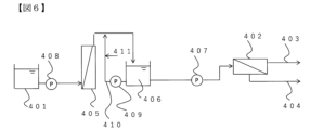
- the freshwater production method of the present invention is implemented in a freshwater production system in which water to be treated 401 is pretreated using an ultrafiltration membrane, then treated using a reverse osmosis membrane 402, and separated into permeate 403 and concentrated water 404.
- water to be treated examples include seawater, brackish water, river water, lake water, groundwater, sewage, and secondary sewage treatment water. Since the water to be treated contains solid components such as turbidity, if it is directly filtered using a reverse osmosis membrane, the solid components will adhere to the membrane surface in large amounts, causing a sudden rise in differential pressure and making operation impossible. For this reason, the water to be treated 401 is first treated in a pretreatment process 405 to produce reverse osmosis membrane feed water 406, which is then supplied to the reverse osmosis membrane.
- the reverse osmosis membrane feed water 406 which has a biopolymer concentration of 75 ⁇ g C/L or less by pretreatment, is supplied to the reverse osmosis membrane from the treated water 1 having a biopolymer concentration of 100 ⁇ g C/L or more. It is more preferable to supply the reverse osmosis membrane feed water 406, which has a biopolymer concentration of 50 ⁇ g C/L or less by pretreatment, to the reverse osmosis membrane from the treated water 401 having a biopolymer concentration of 100 ⁇ g C/L or more.
- the biopolymer concentration of the treated water 401 having a biopolymer concentration of 100 ⁇ g C/L or more to less than 20 ⁇ g C/L by pretreatment so it is preferable to supply the reverse osmosis membrane feed water 406 to the reverse osmosis membrane with a biopolymer concentration of 20 ⁇ g C/L or more.
- Biopolymers are hydrophilic organic polymers (polysaccharides, proteins, etc.) with a molecular weight of 10 to 20 kDa or more.
- biopolymers see, for example, Huber, S. A., Balz, A., Abert, M., Pronk, W., 2011. Characterization of aquatic humic and non-humic matter with size-exclusion chromatography e organic carbon detection e organic carbon detection e organic nitrogen detection (LC-OCD-OND).
- TOC can be measured by organic carbon exclusion chromatography (LC-OCD).
- the LC-OCD method is an analytical method in which TOC components in a sample are fractionated by molecular weight and displayed as a chromatogram, and on the chromatogram, organic substances with larger molecular weights and hydrophilicity tend to have shorter retention times.
- the measurement conditions for the LC-OCD method are a 250 mm x 20 mm TSK HW50S column, a flow rate of 1.1 mL/min, a sample injection amount of 1 mL, a UV wavelength of 254 nm, an acid injection amount to the OCD meter of 0.2 mL/min, a pH 6.85 phosphate buffer as the eluent, and a solution of 4 mL O-phosphoric acid (85%) and 0.5 g potassium peroxodisulfate added to 1 L of ultrapure water as the acidification solution.
- an LC-OCD device manufactured by DOC-Labar
- OCD meter wet total organic carbon meter
- HPLC high performance liquid chromatography
- the porous membrane of the present invention can be used as an ultrafiltration membrane. That is, the water production method of the present invention can use, as the ultrafiltration membrane, a porous membrane containing polyvinylidene fluoride resin, having a surface A and a surface B, in which, in an ATR (attenuated total reflection) method of surface A, the ratio (H ⁇ /H ⁇ ) of ⁇ -structure crystals (H ⁇ ) to ⁇ -structure crystals (H ⁇ ) in the crystal part of the polyvinylidene fluoride resin is 0 to 0.50, the pure water permeability is 0.25 m 3 /m 2 /h/50 kPa to 1.2 m 3 /m 2 /h/50 kPa, and the average surface pore size on surface A of the porous membrane is 5.0 nm to 12.0 nm.
- a porous membrane with a removal rate of 40,000 Da dextran of 45% or more and 80% or less is preferable.
- a dextran removal rate of 45% or more and 80% or less it is possible to prevent coarse contaminants and objects to be removed in the raw filtrate from penetrating into the membrane, and it is easy to show excellent resistance to dirt.
- the biopolymer removal rate of the membrane is easy to be high, and the amount of flocculant added can be reduced or no flocculant can be used at all, making it possible to reduce the biopolymer concentration of the reverse osmosis membrane feed water to 75 ⁇ g C/L or less.
- No flocculant is added to the water to be treated means that no flocculant is added to the water to be treated, that is, the water to be treated does not use a flocculant.
- the type of flocculant is not limited as long as it flocculates biopolymers, and the concentration of the flocculant corresponds to 0% to 0.05%.
- the dextran removal rate of the ultrafiltration membrane with a weight average molecular weight of 40,000 Da is 45% or more and 80% or less, and further 50% or more and 80% or less.
- the reverse osmosis membrane 2 may be made of any material that can reduce the salt concentration so that the treated water can be used as drinking water, industrial water, municipal water, etc.
- Examples include membranes made of cellulose acetate and polyamide materials. Of these, those made of polyamide materials are particularly effective in the method of the present invention.
- Polyamide membranes have low resistance to chlorine, which is most commonly used as a disinfectant to prevent the growth of biofilms, and even small concentrations of chlorine cause significant membrane deterioration, making it difficult to prevent biofouling. Therefore, the effects of implementing the present invention are evident.
- the rate of decrease in permeability of the reverse osmosis membrane is preferably 0.20 (%/hr) or less, and more preferably 0.18 (%/hr) or less.
- Ratio of ⁇ type/ ⁇ type structure crystals H ⁇ /H ⁇ Equation (1).
- T ⁇ (refractive index of undiluted solution) - (refractive index of permeated solution) ⁇ / (refractive index of undiluted solution) x 100 ... formula (2).
- the hollow fiber membrane was cut once by moving the blade close to it at 5 ⁇ m intervals. After that, the moving distance was set to 40 ⁇ m, and cutting was performed once more to collect a hollow fiber membrane section having a thickness of 40 to 45 ⁇ m from the surface.
- the slices were set in a DSC (SEIKO DSC6200) and the temperature was raised from room temperature to 300°C at 5°C/min, the endothermic peak of each polymer resin was regarded as the heat of fusion, and the heat was divided by the heat of complete crystalline fusion of the polymer resin to calculate as a percentage.
- the endothermic peak observed in the range of 100 to 190°C was regarded as the heat of fusion of the polyvinylidene fluoride resin, and the heat was divided by 104.6 J/g, which is the heat of complete crystalline fusion of the polyvinylidene fluoride resin, to calculate as a percentage.
- (vi) Self-diffusion coefficient of polymer The self-diffusion coefficient was determined by all-atom molecular dynamics calculation. A polymer solution system was prepared so that the polymer concentration (wt%) would be the concentration actually used. At this time, one model polymer chain was modeled so that the molecular weight was 800 to 6000 and 1/200 to 1/5 of the weight average molecular weight of the polymer actually used. GAFF2 was used as the potential parameter used in the molecular dynamics calculation. A constant pressure and temperature ensemble was constructed by controlling the temperature to 25°C and the pressure to 1 bar.
- the short-range Lennard-Johns interaction was handled by applying a switch function from 1.0 nm and cutting off at 1.2 nm, and the long-range electrostatic interaction was calculated by the Particle Mesh Ewald method.
- the unit cell length was adjusted to obtain the average density, and an additional calculation of 11 ns was performed in the constant temperature ensemble.
- the mean square displacement (MSD) of each atom of the polymer was determined using a 10 ns trajectory, and the self-diffusion coefficient was calculated from the following formula (3).
- the pore sizes of 1000 or more pores are averaged.
- the number of cross-sectional pores is divided by the area of the analyzed region to obtain the number of pores per unit area.
- an image containing 1000 or more pores is analyzed and calculated.
- the standard deviation of each cross-sectional pore size was calculated.
- the total perimeter of the cross-sectional pore size was calculated by binarizing the TEM image of the cross-section of the porous membrane as described above, selecting Perim in Analyze Particles, and dividing the total by the area of the observed region.
- a 250 mm ⁇ 20 mm TSK HW50S column was used, the flow rate was 1.1 mL/min, the sample injection amount was 1 mL, the UV wavelength was 254 nm, the acid injection amount to the OCD meter was 0.2 mL/min, pH 6.85 phosphate buffer was used as the eluent, and 4 mL O-phosphoric acid (85%) and 0.5 g potassium peroxodisulfate were added to 1 L of ultrapure water as the acidification solution.
- (x) Permeability Reduction Rate of Reverse Osmosis Membrane The reverse osmosis membrane was operated at a pressure of 5.5 MPa and a recovery rate of 37%. The recovery rate is calculated by the flow rate of reverse osmosis membrane permeate water/(flow rate of reverse osmosis membrane permeate water+flow rate of reverse osmosis membrane concentrated water) ⁇ 100.
- the permeability reduction rate of the reverse osmosis membrane was calculated based on the formula (4) using the flow rate of the permeate water 1 hour after the start of operation of the reverse osmosis membrane and the flow rate 50 hours after the start of operation.
- the amount of permeate water (g) for 5 minutes was used as each flow rate.
- Permeability decrease rate of reverse osmosis membrane [%/hr] (permeated water amount [g] after 51 hours from the start of operation)/(permeated water amount [g] after 1 hour from the start of operation)/50 ⁇ 100 (Equation (4)).
- Example 1 The porous membrane used was a hollow fiber porous membrane containing a support obtained by the following manufacturing method. 38% by mass of PVDF (Kureha Corporation; KF1300, weight average molecular weight 350,000 Da) and 62% by mass of ⁇ -butyrolactone were mixed and dissolved at 160°C to prepare a support membrane stock solution. This support membrane stock solution was discharged from a double-tube nozzle while accompanying an 85% by mass ⁇ -butyrolactone aqueous solution as a hollow portion forming liquid.
- the discharged support membrane stock solution was solidified in a cooling bath containing an 85% by mass ⁇ -butyrolactone aqueous solution at a temperature of 20°C installed 30 mm below the nozzle, to produce a hollow fiber support having a spherical structure.
- PVDF1 Arkema; Kynar (registered trademark) 710, weight average molecular weight 180,000 Da
- cellulose diacetate Eastman; CA-398-3
- cellulose triacetate Eastman; CA-436-80S
- NMP 68.7% by mass of NMP
- 12.1% by mass of 2P were mixed and stirred at 120°C for 4 hours to prepare a polymer solution with the composition ratio shown in Table 1.
- the polymer solution was uniformly applied to the outer surface of the hollow fiber support at 10 m/min (thickness 50 ⁇ m).
- the support to which the polymer solution was applied was immersed in a coagulation bath of distilled water at 35° C. for 10 seconds to coagulate, forming a porous membrane having a three-dimensional mesh structure.
- the evaluation results of the obtained porous membrane are shown in Table 1.
- the surface portion of the porous membrane from the surface to a thickness of 10 ⁇ m was denser than the inside.
- An image of the cross section of the outermost surface portion of the porous membrane observed with a TEM is shown in FIG. 5.
- the porous membrane had a nanomesh structure based on the cross-sectional pore size and the number of cross-sectional pores.
- the H ⁇ /H ⁇ of the obtained porous membrane was 0.37
- the pure water permeability was 0.43 m 3 /m 2 /h/50 kPa
- the dextran removal rate was 55%, which were good.
- the crystallinity of the outer surface resin was high at 49%.
- the value X obtained by dividing the number of surface pores by the average surface pore diameter was 66
- the average surface pore diameter was 7.2 nm
- the standard deviation was 2.5.
- Example 2 A porous membrane was obtained in the same manner as in Example 1, except that the NMP in the polymer solution was changed to DMSO and the distilled water in the coagulation bath was set to 40°C.
- the evaluation results of the porous membrane are shown in Table 1.
- the surface portion of the porous membrane up to a thickness of 10 ⁇ m from the surface was denser than the inside.
- the H ⁇ / H ⁇ of the obtained porous membrane was 0.27, the pure water permeability was 0.29 m3 / m2 /h/50 kPa, and the dextran removal rate was 63%, which were good results.
- Example 3 A porous membrane was obtained in the same manner as in Example 1, except that the NMP in the polymer solution was changed to DMF and the distilled water in the coagulation bath was set to 25° C.
- the evaluation results of the porous membrane are shown in Table 1.
- the surface portion of the porous membrane up to a thickness of 10 ⁇ m from the surface was denser than the inside.
- the H ⁇ / H ⁇ of the obtained porous membrane was 0.24, the pure water permeability was 0.45 m3 / m2 /h/50 kPa, and the dextran removal rate was 47%, which were good results.
- Example 1 In the membrane production of Example 1, the solvent in the polymer solution was all NMP, and a porous membrane was obtained in the same manner, except that the composition ratio was changed. The evaluation results of the porous membrane are shown in Table 2.
- the porous membrane did not have a nanomesh structure.
- the surface part of the porous membrane from the surface to a thickness of 10 ⁇ m was denser than the inside.
- the H ⁇ /H ⁇ of the obtained porous membrane was 1.0, the pure water permeability was 0.41 m 3 /m 2 /h/50 kPa, and the dextran removal rate was 55%.
- X was 13, the average surface pore size was 15 nm, and the standard deviation was 6.0.
- the crystallinity of the outer surface resin was low at 11%.
- the initial ratio (F2/F1) of the filtration flux after the permeation volume reached 400 L/m 2 (F2) to the initial ratio (F1) of the filtration flux immediately after the start of filtration was 0.38, and the filtration flux could not be maintained after long-term use.
- Comparative Example 2 A porous membrane was obtained by the same membrane production as in Comparative Example 1 except that the coagulation bath temperature was 6°C. The evaluation results of the porous membrane are shown in Table 2. The surface portion of the porous membrane from the surface to a thickness of 10 ⁇ m was denser than the inside. The H ⁇ / H ⁇ of the obtained porous membrane was 0.10, the pure water permeability was 0.10 m3 / m2 /h/50 kPa, and the dextran removal rate was 70%, which did not satisfy the conditions. Furthermore, X was 10, the average surface pore size was 8.0 nm, and the standard deviation was 1.9.
- Example 3 In the film formation of Example 1, PVDF1 in the polymer solution was replaced with PVDF2 (Solef9009 manufactured by Solvay) and the composition ratio was changed, and the film was formed in the same manner as in Comparative Example 1 to obtain a porous film.
- the evaluation results of the porous film are shown in Table 2.
- the porous film did not have a nanomesh structure.
- the surface part of the porous film from the surface to a thickness of 10 ⁇ m was denser than the inside.
- the H ⁇ /H ⁇ of the obtained porous film was 0.22, the pure water permeability was 0.21 m 3 /m 2 /h/50 kPa, and the dextran removal rate was 57%.
- a porous membrane was obtained by forming a membrane in the same manner as in Example 1, except that the distilled water in the coagulation bath was set to 21 ° C. The evaluation results of the porous membrane are shown in Table 2.
- the H ⁇ /H ⁇ of the obtained porous membrane was 0.63, the pure water permeability was 0.022 m 3 /m 2 /h / 50 kPa, and the dextran removal rate was 66%, which did not satisfy the conditions. Furthermore, X was 0.90, the average surface pore size was 15 nm, and the standard deviation was 8.5. (vii) When the long-term stability was evaluated by the filtration evaluation method for industrial wastewater, the amount of permeated liquid was extremely small, making it difficult to measure the filtration flux.
- Example 4 In the flow shown in Figure 6, the permeate water of the reverse osmosis membrane was produced from the water to be treated. That is, seawater 1 (biopolymer concentration 122 ⁇ g C/L) was used as the water to be treated, and the porous membrane of Example 1 was used for pretreatment. As a result, the biopolymer concentration of the reverse osmosis membrane feed water was 35 ⁇ g C/L.
- This reverse osmosis membrane feed water was pressurized with a high-pressure pump and filtered through the reverse osmosis membrane to obtain permeate water.
- the reverse osmosis membrane was a spiral reverse osmosis membrane with a polyamide membrane material, a salt rejection rate of 99.8%, and a membrane area of 37 m2 .
- the initial permeability ratio of the ultrafiltration membrane was 0.71
- the permeability decrease rate of the reverse osmosis membrane was 0.15%/hr.
- Example 5 In the flow shown in Figure 6, permeated water of the reverse osmosis membrane was produced from the water to be treated. That is, seawater 2 (biopolymer concentration 218 ⁇ g C/L) was used as the water to be treated, and the porous membrane of Example 1 was used for pretreatment. As a result, the biopolymer concentration of the reverse osmosis membrane feed water was 47 ⁇ g C/L.
- This reverse osmosis membrane feed water was pressurized with a high-pressure pump and filtered through the reverse osmosis membrane to obtain permeated water.
- the reverse osmosis membrane was a spiral reverse osmosis membrane with a polyamide membrane material, a salt rejection rate of 99.8%, and a membrane area of 37 m2 .
- the initial permeability ratio of the ultrafiltration membrane was 0.63
- the permeability decrease rate of the reverse osmosis membrane was 0.18%/hr.
- the permeate water of the reverse osmosis membrane was produced from the water to be treated. That is, seawater 1 (biopolymer concentration 122 ⁇ g C/L) was used as the water to be treated, and the porous membrane of Comparative Example 1 was used for pretreatment. As a result, the biopolymer concentration of the reverse osmosis membrane feed water was 85 ⁇ g C/L.
- This reverse osmosis membrane feed water was pressurized with a high-pressure pump and filtered through the reverse osmosis membrane to obtain permeate water.
- the reverse osmosis membrane was a spiral reverse osmosis membrane with a polyamide membrane material, a salt rejection rate of 99.8%, and a membrane area of 37 m2 .
- the initial permeability ratio of the ultrafiltration membrane was 0.53
- the permeability decrease rate of the reverse osmosis membrane was 0.25%/hr, showing that the permeability decrease rate of the reverse osmosis membrane was large.
- Table 3 The results are shown in Table 3.
- the permeate water of the reverse osmosis membrane was produced from the water to be treated. That is, seawater 2 (biopolymer concentration 218 ⁇ g C/L) was used as the water to be treated, and the porous membrane of Comparative Example 1 was used for pretreatment. As a result, the biopolymer concentration of the reverse osmosis membrane feed water was 139 ⁇ g C/L.
- This reverse osmosis membrane feed water was pressurized with a high-pressure pump and filtered through the reverse osmosis membrane to obtain permeate water.
- the reverse osmosis membrane was a spiral reverse osmosis membrane with a polyamide membrane material, a salt rejection rate of 99.8%, and a membrane area of 37 m2 .
- the initial permeability ratio of the ultrafiltration membrane was 0.45
- the permeability decrease rate of the reverse osmosis membrane was 0.45%/hr.
- the biopolymer concentration in the treated water was very high
- the permeability decrease of the ultrafiltration membrane was large, and the permeability decrease rate of the reverse osmosis membrane was also significantly large.
Landscapes
- Chemical & Material Sciences (AREA)
- Engineering & Computer Science (AREA)
- Water Supply & Treatment (AREA)
- Chemical Kinetics & Catalysis (AREA)
- Life Sciences & Earth Sciences (AREA)
- Hydrology & Water Resources (AREA)
- Environmental & Geological Engineering (AREA)
- Organic Chemistry (AREA)
- Nanotechnology (AREA)
- Separation Using Semi-Permeable Membranes (AREA)
Abstract
Description
(1)ポリフッ化ビニリデン樹脂を含む多孔質膜であって、一方の面を表面A、もう一方の面を表面Bとし、前記表面AにおいてATR法(全反射測定法)で測定される、ポリフッ化ビニリデン樹脂の結晶部におけるα型構造結晶(Hα) とβ型構造結晶(Hβ)の比率(Hα/Hβの比)が0以上0.50以下であり、且つ前記多孔質膜の純水透水性が0.25m3/m2/h/50kPa以上1.2m3/m2/h/50kPa 以下であり、前記多孔質膜の表面Aにおける表面孔の表面孔径の平均値が5.0nm以上12.0nm以下である多孔質膜である。
(2)前記多孔質膜の表面Aにおける前記フッ化ビニリデン樹脂の結晶化度が30%以上である(1)に記載の多孔質膜である。
(3)前記多孔質膜の4万Daデキストランの除去率が45%以上80%以下である(1)または(2)に記載の多孔質膜である。
(4)前記多孔質膜の表面Aにおける前記表面孔の数[個/μm2]を前記表面孔径の平均値[nm]で除した値:Xが30個/μm2/nm以上100個/μm2/nm以下である(1)~(3)のいずれかに記載の多孔質膜である。
(5)前記多孔質膜の表面Aにおける前記表面孔径の標準偏差が1.0nm以上5.0nm以下である(1)~(4)のいずれかに記載の多孔質膜である。
(6)前記多孔質膜の表面Aから厚み10μmまでの表面部が、内部より緻密である(1)~(5)のいずれかに記載の多孔質膜である。
(7)(1)~(6)のいずれかに記載の多孔質膜を用いた液体のろ過方法である。
(8)(1)~(6)のいずれかに記載の多孔質膜を備える膜ろ過装置である。
(9)被処理水を前処理して逆浸透膜供給水を得る前処理工程と、前記逆浸透膜供給水を逆浸透膜でろ過して透過水を得る逆浸透膜処理工程を含む造水方法において、前記被処理水はバイオポリマー濃度が100μgC/L以上の被処理水であり、前処理によってバイオポリマー濃度を75μgC/L以下とした前記逆浸透膜供給水を逆浸透膜に供給する造水方法であり、
前記前処理工程が限外ろ過膜を備える限外ろ過膜処理部を有し、前記限外ろ過膜が(1)~(6)のいずれかに記載の多孔質膜である、造水方法である。
(10)前記多孔質膜の表面Aにおける表面孔の数が200個/μm2以上2000個/μm2以下である(9)に記載の造水方法である。
(11)前記前処理工程の前記限外ろ過膜処理において、前記被処理水に凝集剤が含まれないことを特徴とする、(9)または(10)に記載の造水方法。
本発明の実施形態に係る多孔質膜は、ポリフッ化ビニリデン樹脂を含む多孔質膜であって、表面Aと表面Bを有し、表面AのATR法(全反射測定法)で測定されるIRスペクトルにおいて、ポリフッ化ビニリデン樹脂の結晶部におけるα型構造結晶(Hα)とβ型構造結晶(Hβ)の比率(Hα/Hβ比)が0以上0.5以下であり、且つ純水透水性が0.25m3/m2/h/50kPa以上1.2m3/m2/h/50kPa以下であることを必要とする。なお、Hα/Hβの比が0とはβ型構造結晶(Hβ)が100%であることを示す。
α型/β型構造結晶の比率=Hα/Hβ・・・・式(1)。
T={(原液の屈折率)-(透過液の屈折率)}/(原液の屈折率)×100 ・・・・式(2)
ここで、クロスフロー線速度は、ろ過原液のろ過方向と垂直な方向の流量を、該流れの流路の断面積で除した値である。また、膜間差圧とは、多孔質膜を隔てたろ過原液側の圧力と、透過液側の圧力の差である。
表面孔の数を表面孔径の平均値で除した値:Xが30個/μm2/nm以上100個/μm2/nm以下であることで、ろ過原液中の汚れ成分が細孔内に侵入を防ぎ、且つ透過液が多孔質膜を透過する流路の数を十分に確保できるため、透過液性を示しやすく、好ましい。Xは50個/μm2/nm以上100個/μm2/nm以下であることがさらに好ましく、60個/μm2/nm以上100個/μm2/nm以下であることがさらに好ましい。多孔質膜の表面孔の数は、表面孔径を求めた場合と同様に多孔質膜の表面を観察したSEMで得た画像を二値化してAnalyze Particlesで解析して得ることができる。解析した画像の面積で、表面孔の数を除すことで、単位面積当たりの孔の数とする。孔径と同様に孔1000個以上を含む画像を解析して算出する。
本発明の多孔質膜は、工程(A)高分子を溶媒に溶解して高分子溶液を得る工程と、その後に、工程(B)高分子溶液を非溶媒中で凝固させて多孔質膜を形成する多孔質膜形成工程とを含み、工程(A)で得られる高分子溶液中において、溶解された高分子の全原子分子動力学計算で算出される自己拡散係数[m2/sec]が0.8×10-11m2/sec~1.6×10-11m2/secで、工程(B)で用いる非溶媒が90~100重量%の水を含み、かつ、非溶媒の温度が6℃~45℃とする製造方法で得ることができる。
ここで、工程(B)の「非溶媒」とは、非溶媒を沸点まで高温にしても、高分子を溶解も膨潤もさせない溶媒をいう。非溶媒としては、例えば、水、ヘキサン、ペンタン、ベンゼン、トルエン、メタノール、エタノール、四塩化炭素、o-ジクロルベンゼン、トリクロルエチレン、エチレングリコール、ジエチレングリコール、トリエチレングリコール、プロピレングリコール、ブチレングリコール、ペンタンジオール、ヘキサンジオール若しくは低分子量のポリエチレングリコール等の脂肪族炭化水素、芳香族炭化水素、脂肪族多価アルコール、芳香族多価アルコール、塩素化炭化水素、又は、その他の塩素化有機液体あるいはそれらの混合溶媒が挙げられる。高分子溶液における高分子の濃度(重量%)は、自己拡散係数を適した範囲に制御するために、絡み合い濃度以上とすることが好ましく、より具体的には、10~40重量%が好ましく、12~30重量%がさらに好ましく、15~25重量%が特に好ましい。
D:自己拡散係数 t:時間
本発明の多孔質膜の製造において、凝固に用いる非溶媒が90~100重量%の水を含むことで、凝固が早く、高分子溶液における自己拡散係数が、相分離および粗大化の速度に影響を与えやすい。また、非溶媒の温度が6℃~45℃であることで、凝固が早く、高分子溶液における自己拡散係数が、相分離および粗大化の速度に影響を与えやすい。非溶媒の温度は35℃~40℃であることが好ましい。非溶媒の温度を35℃~40℃とすることで、特に凝固が速くなり、結晶形態はβ型構造結晶を多く生成することができる。つまり、上述したように高分子溶液中の高分子の自己拡散係数低い範囲に抑えつつ、かつ、高分子溶液中の溶媒と凝固浴中の非溶媒を効率的に交換し、より凝固を速めることで、β型構造結晶の割合を高めることと、且つ表面孔の数が多いことを両立する多孔質膜を得ることができる。
島津製作所株式会社のIRTracer-100を用いて、ATR法(全反射測定法)により分解能8cm-1で膜表面のIRスペクトルを測定した。測定面積、得られたスペクトルにおいて763cm-1の位置に現れるα型構造結晶のシグナルのピーク高さ(Hα)と、840cm-1に現れるβ 型構造結晶のシグナルのピーク高さ(Hβ)から、次式を用いてα型構造結晶とβ 型構造結晶の比率を算出した。
中空糸膜1~10本程度からなる長さ約10cmの小型モジュールを作製し、温度25℃、ろ過差圧18.6kPaの条件で表面Aから蒸留水を送液して全量ろ過し、一定時間の透過水量(m3)を測定して得た値を、単位時間(hr)、単位有効膜面積(m2)、50kPa当たりに換算して算出した。
デキストラン(Aldrich社製;重量平均分子量4万Da)を1000ppm蒸留水に混合して、デキストラン水溶液を調製した。調製したデキストラン水溶液を25℃で多孔質膜に膜間差圧10kPaとなるように供給して、クロスフロー線速度1.0m/secでクロスフローろ過し、透過液をサンプリングした。透過液をサンプリングしたタイミングで多孔質膜に供給したデキストラン水溶液(原液)をサンプリングした。透過液と原液の屈折率を測定し、式(2)に基づいて除去率:Tを求めた。
T={(原液の屈折率)-(透過液の屈折率)}/(原液の屈折率)×100・・・・式(2) 。
中空糸膜形状の多孔質膜の高分子樹脂の結晶化度の測定を示す。測定には中空糸膜の外表面から50μm以内の切片を用いた。中空糸膜の外表面を、市販の凍結ミクロトーム(Leica社製;Jung CM3000)で切開しサンプルを採取した。蒸留水中に浸漬した中空糸膜を、凍結ミクロトーム(Leica社製;Jung CM3000)を用いて-20℃で凍結し、中空糸膜の表面に平行な向きに刃を設置した。まず、移動距離を5μm間隔で刃に近づけて中空糸膜を1回切削した。その後、移動距離を40μmとして、さらに1回切削することで、表面から厚み40~45μmの中空糸膜切片を採取した。DSC(SEIKO製:DSC6200)に切片セットして室温から300℃まで5℃/分で上昇させたとき、それぞれの高分子樹脂の吸熱ピークを融解熱とみなし、該熱量を高分子樹脂の完全結晶融解熱量で除し、百分率として算出した。例えば、ポリフッ化ビニリデン系樹脂については、100~190℃の範囲に見られる吸熱ピークをポリフッ化ビニリデン系樹脂の融解熱と見なし、該熱量を、ポリフッ化ビニリデン系樹脂の完全結晶融解熱量である104.6J/gで除して、百分率として算出した。
多孔質膜を25℃で1晩、真空乾燥した後、SEM(株式会社日立ハイテクノロジーズ製;S-5500)を用いて、3万~10万倍の倍率で観察した。多孔質膜の表面を観察したSEMで得た画像を、フリーソフト「ImageJ」を使って二値化した。二値化する際は、Subtract Backgroundにて1pixelとしてCreate Backgroundした後、Threshold(二値化の閾値)で条件:RenyiEntropyを選択した。得られた二値化画像において、Analyze ParticlesでAreaを選択することで、各孔の面積を求め、各孔を円と仮定して算出した直径を表面孔径とした。表面孔径の平均値を求める際は、孔1000個以上の孔径を平均して求めた。同様に、各表面孔径の標準偏差を求めた。孔の数は、観察した領域の面積で除して、単位面積当たりの孔数とした。
自己拡散係数は、全原子分子動力学計算によって決定した。実際に使用する高分子濃度(重量%)となるように高分子溶液系を作成した。このときモデル高分子鎖1本を、分子量が800~6000であり、かつ実際に使用する高分子の重量平均分子量の1/200~1/5となるようにモデリングした。分子動力学計算で用いるポテンシャルパラメータには、GAFF2を用いた。温度を25℃に、圧力を1barに制御することで圧力・温度一定アンサンブルを構成した。このとき、近距離のLennard-Johns相互作用は、1.0nmからスイッチファンクションを適用し、1.2nmでカットオフすることで取り扱い、長距離の静電相互作用はParticle Mesh Ewald法で計算した。圧力・温度一定アンサンブルで、密度が一定になるまで分子動力学計算を実施した後、平均の密度になるようにユニットセル長を調整し、温度一定アンサンブルで11nsの追加計算を行った。10nsの軌跡を用いて、高分子の各原子の平均二乗変位(MSD)を求め、下記式(3)から自己拡散係数を算出した。このとき、Dの算出に用いるMSDとtの範囲は、log(MSD)をlog(t)で除した値が0.9~1.1の範囲にあることを確認した。複数種の高分子を混合して高分子溶液とする場合、各高分子の自己拡散係数を、高分子の重量%を基に加重平均した値を高分子溶液中の高分子の自己拡散係数とした。
D=MSD/6t ・・・・・式(3)
D:自己拡散係数 t:時間 。
化学工場の廃水(TOC;30mg/L、濁度;11NTU)を25℃で多孔質膜に膜間差圧100kPaとなるように供給して全量ろ過し、透過液量を測定した。透過液量が28L/m2となった際に、膜間差圧150kPaとなるように逆ろ過透過量が3L/m2となるまで逆ろ過を実施した。ろ過と逆ろ過を繰り返し行い、ろ過開始直後のろ過流束(F1)と、単位面積当たりの透過液量が400L/m2以上となった後のろ過開始直後(F2)ときのろ過流束の比(F2/F1):ろ過流束の初期比を算出した。ろ過流束の初期比は1に近いほど初期の特性が維持されており、長時間の使用後も多孔質膜は詰まりにくく良好なろ過ができる目安は50%以上である。
市販の凍結組織切片作成用包埋剤(ティシュー・テック社製;O.C.T.コンパウンド)を用いて包埋した多孔質膜を、クライオウルトラミクロトーム(Leica製;FC7)を用いて、-40℃で多孔質膜を表面と垂直な向きに100nmの厚みの切片を採取し、室温で12時間真空乾燥を行った。多孔質膜の最表面部の断面をTEM(日本電子社製;JEM-1400Plus)で観察し、画像を得て、フリーソフト「ImageJ」を使って二値化した。二値化する際は、Threshold(二値化の閾値)で条件:Minimumを選択した。得られた二値化画像において、Analyze ParticlesでAreaを選択することで、各孔の面積を求め、各孔を円と仮定して算出した直径を断面孔径とした。
被処理水および逆浸透膜供給水のバイオポリマー濃度は、Huber,S.A.,Balz,A.,Abert, M., Pronk, W., 2011.Characterisation of aquatic humic and non-humic matter with size-exclusion chromatography e organic carbon detection e organic carbon detection e organic nitrogen detection(LC-OCD-OND).Water Research 45(2),879-885に記載されているように、有機炭素検出型排除クロマトグラフ法(LC-OCD)で測定した。カラムとして250mm×20mm TSK HW50Sを用い、流速を1.1mL/minにし、サンプル注入量を1mLにし、UV波長を254nmにし、OCD計への酸注入量を0.2mL/minにし、溶離液としてpH6.85 リン酸バッファを用い、酸性化溶液として1L超純水に対し、4mL O-リン酸(85%)およびペルオキソ二硫酸カリウム0.5gを添加した。
逆浸透膜は、圧力5.5MPa、回収率37%で運転した。回収率とは逆浸透膜透過水の流量/(逆浸透膜透過水の流量+逆浸透膜濃縮水の流量)×100で算出される。 ここで、逆浸透膜の透水性低下率は、逆浸透膜の運転開始1時間後の透過水の流量と、運転開始50時間後の流量を用いて、式(4)に基づいて求めた。ここで、それぞれの流量は、5分間の透過水量(g)を用いた。
逆浸透膜の透水性低下率[%/hr]=(運転開始51時間後の透過水量[g])/(運転開始1時間後の透過水量[g])/50×100 ・・・式(4) 。
被処理水を限外ろ過膜に膜間差圧100kPaとなるように供給して全量ろ過し、透過水量を測定した。透過水量が28L/m2となった際に、膜間差圧150kPaとなるように逆ろ過透水量が3L/m2となるまで逆ろ過を実施した。ろ過と逆ろ過を繰り返し行い、限外ろ過膜でのろ過開始直後の透過水の流量F1(g)と、単位面積あたりの透過液量が400L/m2以上となった後のろ過開始直後の透過水の流量F2(g)を測定する。ここで、それぞれの流量は、5分間の透過水量(g)を用い、透過水の流量の比(F2/F1)を算出し、透水性初期値比とした。
多孔質膜は以下の製法で得た支持体を含む中空糸多孔質膜を用いた。38質量%のPVDF(クレハ社製;KF1300、重量平均分子量35万Da)と、62質量%のγ-ブチロラクトンを混合し、160℃で溶解して、支持膜原液を調製した。この支持膜原液を、85質量%γ-ブチロラクトン水溶液を中空部形成液体として随伴させながら二重管口金から吐出した。吐出した支持膜原液を、口金の30mm下方に設置した温度20℃の85質量%γ-ブチロラクトン水溶液が入った冷却浴中で凝固させて、球状構造を有する中空糸状の支持体を作製した。
(vii)工場廃水のろ過評価方法で、長時間安定性を評価したところ、透過液量が400L/m2後(F2)とろ過開始直後(F1)とのろ過流束の初期比(F2/F1)は0.63であり、長時間の使用後もろ過流束を維持できた。
実施例1の製膜において、ポリマー溶液におけるNMPをDMSOに変更し、凝固浴の蒸留水を40℃とした以外は、同様に製膜して多孔質膜を得た。多孔質膜の評価結果を表1に示す。多孔質膜は表面から厚み10μmまでの表面部が、内部より緻密であった。得られた多孔質膜のHα/Hβは0.27、純水透水性は0.29m3/m2/h/50kPa、デキストラン除去率は63%と良好であった。
実施例1の製膜において、ポリマー溶液におけるNMPをDMFに変更し、凝固浴の蒸留水を25℃とした以外は、同様に製膜して多孔質膜を得た。多孔質膜の評価結果を表1に示す。多孔質膜は表面から厚み10μmまでの表面部が、内部より緻密であった。得られた多孔質膜のHα/Hβは0.24、純水透水性は0.45m3/m2/h/50kPa、デキストラン除去率は47%と良好であった。
実施例1の製膜において、高分子溶液における溶媒を全てNMPとし、組成比を変更した以外は、同様に製膜して多孔質膜を得た。多孔質膜の評価結果を表2に示す。多孔質膜はナノ網目構造を有していなかった。多孔質膜は表面から厚み10μmまでの表面部が、内部より緻密であった。得られた多孔質膜のHα/Hβは1.0、純水透水性は0.41m3/m2/h/50kPa、デキストラン除去率は55%であった。さらに、Xは13で平均表面孔径は15nm、標準偏差は6. 0であった。また、外表面部樹脂の結晶化度は11%と低かった。(vii)工場廃水のろ過評価方法で、長時間安定性を評価したところ、透過液量が400L/m2後(F2)とろ過開始直後(F1)とのろ過流束の初期比(F2/F1)は0.38であり、長時間の使用後はろ過流束を維持できなかった。
比較例1の製膜において、凝固浴温度を6℃とした以外は、同様に製膜して多孔質膜を得た。多孔質膜の評価結果を表2に示す。多孔質膜は表面から厚み10μmまでの表面部が、内部より緻密であった。得られた多孔質膜のHα/Hβは0.10、純水透水性は0.10m3/m2/h/50kPa、デキストラン除去率は70%であり条件を満たさなかった。さらに、Xは10で平均表面孔径は8.0nm、標準偏差は1.9であった。(vii)工場廃水のろ過評価方法で、長時間安定性を評価したところ、透過液量が400L/m2後(F2)とろ過開始直後(F1)とのろ過流束の初期比(F2/F1)は0.37であり、長時間の使用後はろ過流束を維持できなかった。
実施例1の製膜において、高分子溶液におけるPVDF1をPVDF2(ソルベイ社製:Solef9009)とし、組成比を変更した以外は、比較例1と同様に製膜して多孔質膜を得た。多孔質膜の評価結果を表2に示す。多孔質膜はナノ網目構造を有していなかった。多孔質膜は表面から厚み10μmまでの表面部が、内部より緻密であった。得られた多孔質膜のHα/Hβは0.22、純水透水性は0.21m3/m2/h/50kPa、デキストラン除去率は57%であった。さらに、Xは7.6で平均表面孔径は10nm、標準偏差は4.1であり、条件を満たさなかった。(vii)工場廃水のろ過評価方法で、長時間安定性を評価したところ、透過液量が400L/m2後(F2)とろ過開始直後(F1)とのろ過流束の初期比(F2/F1)は0.40であり、長時間の使用後はろ過流束を維持できなかった。
高分子溶液を20質量%のPVDF3(クレハ社製;KFポリマー#110、重量平均分子量280000Da)、80質量%の混合溶媒(DMAc:GBL=89:11)を混合して120℃で4時間撹拌し、調製した。他は凝固浴の蒸留水を21℃とした以外は、実施例1と同様に製膜して多孔質膜を得た。多孔質膜の評価結果を表2に示す。得られた多孔質膜のHα/Hβは0.63、純水透水性は0.022m3/m2/h/50kPa、デキストラン除去率は66%であり条件を満たさなかった。さらに、Xは0.90で平均表面孔径は15nm、標準偏差は8.5であった。(vii)工場廃水のろ過評価方法で、長時間安定性を評価したところ、透過液量が著しく少なく、ろ過流束を測定することが困難であった。
図6に示すフローにて、被処理水から逆浸透膜の透過水を造水した。すなわち、海水1(バイオポリマー濃度122μgC/L)を被処理水とし、実施例1の多孔質膜を前処理に用いた結果、逆浸透膜供給水のバイオポリマー濃度は35μgC/Lであった。この逆浸透膜供給水を高圧ポンプで加圧することにより逆浸透膜でろ過し、透過水を得た。逆浸透膜は膜材質がポリアミド、脱塩率が99.8%、膜面積が37m2のスパイラル型の逆浸透膜であった。
図6に示すフローにて、被処理水から逆浸透膜の透過水を造水した。すなわち、海水2(バイオポリマー濃度218μgC/L)を被処理水とし、実施例1の多孔質膜を前処理に用いた結果、逆浸透膜供給水のバイオポリマー濃度は47μgC/Lであった。この逆浸透膜供給水を高圧ポンプで加圧することにより逆浸透膜でろ過し、透過水を得た。逆浸透膜は膜材質がポリアミド、脱塩率が99.8%、膜面積が37m2のスパイラル型の逆浸透膜であった。
図6に示すフローにて、被処理水から逆浸透膜の透過水を造水した。すなわち、海水1(バイオポリマー濃度122μgC/L)を被処理水とし、比較例1の多孔質膜を前処理に用いた結果、逆浸透膜供給水のバイオポリマー濃度は85μgC/Lであった。この逆浸透膜供給水を高圧ポンプで加圧することにより逆浸透膜でろ過し、透過水を得た。逆浸透膜は膜材質がポリアミド、脱塩率が99.8%、膜面積が37m2のスパイラル型の逆浸透膜であった。
図6に示すフローにて、被処理水から逆浸透膜の透過水を造水した。すなわち、海水2(バイオポリマー濃度218μgC/L)を被処理水とし、比較例1の多孔質膜を前処理に用いた結果、逆浸透膜供給水のバイオポリマー濃度は139μgC/Lであった。この逆浸透膜供給水を高圧ポンプで加圧することにより逆浸透膜でろ過し、透過水を得た。逆浸透膜は膜材質がポリアミド、脱塩率が99.8%、膜面積が37m2のスパイラル型の逆浸透膜であった。


102 表面部
103 内部
201 粗大な汚れ成分
202 微細な汚れ成分
300 高分子溶液
301 高分子を多く含む相
302 溶媒を多く含む相
FL ろ過方向
401 被処理水
402 逆浸透膜
403 透過水
404 濃縮水
405 前処理工程
406 逆浸透膜供給水
407 高圧ポンプ
408 送液ポンプ
409 供給ポンプ
410 洗浄剤
411 殺菌剤
Claims (11)
- ポリフッ化ビニリデン樹脂を含む多孔質膜であって、一方の面を表面A、もう一方の面を表面Bとし、前記表面AにおいてATR法(全反射測定法)にて測定される、ポリフッ化ビニリデン樹脂の結晶部におけるα型構造結晶(Hα) とβ型構造結晶(Hβ)の比率(Hα/Hβの比)が0以上0.50以下であり、
且つ前記多孔質膜の純水透水性が0.25m3/m2/h/50kPa以上1.2m3/m2/h/50kPa 以下であり、前記多孔質膜の前記表面Aにおける表面孔の表面孔径の平均値が5.0以上12.0nm以下である多孔質膜。 - 前記多孔質膜の表面Aにおける前記ポリフッ化ビニリデン樹脂の結晶化度が30%以上である請求項1に記載の多孔質膜。
- 前記多孔質膜の4万Daデキストランの除去率が45%以上80%以下である請求項1または2に記載の多孔質膜。
- 前記多孔質膜の表面Aにおける前記表面孔の数[個/μm2]を前記表面孔径の平均値[nm]で除した値:Xが30個/μm2/nm以上100個/μm2/nm以下である請求項1~3のいずれかに記載の多孔質膜。
- 前記多孔質膜の表面Aにおける前記表面孔径の標準偏差が1.0nm以上5.0nm以下である請求項1~4のいずれかに記載の多孔質膜。
- 前記多孔質膜の表面Aから厚み10μmまでの表面部が、内部より緻密である請求項1~5のいずれかに記載の多孔質膜。
- 請求項1~6のいずれかに記載の多孔質膜を用いた液体のろ過方法。
- 請求項1~6のいずれかに記載の多孔質膜を備える膜ろ過装置。
- 被処理水を前処理して逆浸透膜供給水を得る前処理工程と、前記逆浸透膜供給水を逆浸透膜でろ過して透過水を得る逆浸透膜処理工程を含む造水方法において、
前記被処理水はバイオポリマー濃度が100μgC/L以上の被処理水であり、前記前処理工程によってバイオポリマー濃度が75μgC/L以下の前記逆浸透膜供給水を得て、前記逆浸透膜処理工程に供給する造水方法であり、
前記前処理工程が限外ろ過膜を備える限外ろ過膜処理部を有し、
前記限外ろ過膜が請求項1~6のいずれかに記載の多孔質膜である、造水方法。 - 前記多孔質膜の表面Aにおける表面孔の数が200個/μm2以上2000個/μm2以下である請求項9に記載の造水方法。
- 前記前処理工程の前記限外ろ過膜処理において、被処理水に凝集剤を含まないことを特徴とする、請求項9または10に記載の造水方法。
Priority Applications (5)
| Application Number | Priority Date | Filing Date | Title |
|---|---|---|---|
| KR1020257008472A KR20250078440A (ko) | 2022-09-28 | 2023-09-25 | 다공질막 및 조수 방법 |
| AU2023353924A AU2023353924A1 (en) | 2022-09-28 | 2023-09-25 | Porous membrane and desalination method |
| CN202380062540.XA CN119816358A (zh) | 2022-09-28 | 2023-09-25 | 多孔膜及造水方法 |
| EP23872230.0A EP4596088A4 (en) | 2022-09-28 | 2023-09-25 | Porous membrane and desalination method |
| JP2023568518A JP7697531B2 (ja) | 2022-09-28 | 2023-09-25 | 多孔質膜および造水方法 |
Applications Claiming Priority (6)
| Application Number | Priority Date | Filing Date | Title |
|---|---|---|---|
| JP2022154563 | 2022-09-28 | ||
| JP2022-154563 | 2022-09-28 | ||
| JP2022193239 | 2022-12-02 | ||
| JP2022-193239 | 2022-12-02 | ||
| JP2023-034338 | 2023-03-07 | ||
| JP2023034338 | 2023-03-07 |
Publications (1)
| Publication Number | Publication Date |
|---|---|
| WO2024071005A1 true WO2024071005A1 (ja) | 2024-04-04 |
Family
ID=90477810
Family Applications (1)
| Application Number | Title | Priority Date | Filing Date |
|---|---|---|---|
| PCT/JP2023/034640 Ceased WO2024071005A1 (ja) | 2022-09-28 | 2023-09-25 | 多孔質膜および造水方法 |
Country Status (6)
| Country | Link |
|---|---|
| EP (1) | EP4596088A4 (ja) |
| JP (1) | JP7697531B2 (ja) |
| KR (1) | KR20250078440A (ja) |
| CN (1) | CN119816358A (ja) |
| AU (1) | AU2023353924A1 (ja) |
| WO (1) | WO2024071005A1 (ja) |
Citations (8)
| Publication number | Priority date | Publication date | Assignee | Title |
|---|---|---|---|---|
| JP2015073916A (ja) | 2013-10-04 | 2015-04-20 | 旭化成ケミカルズ株式会社 | 多孔性中空糸膜及びその製造方法 |
| JP2017029934A (ja) | 2015-08-03 | 2017-02-09 | 株式会社クラレ | 中空糸膜、及び中空糸膜の製造方法 |
| WO2019044312A1 (ja) * | 2017-08-31 | 2019-03-07 | オルガノ株式会社 | 水処理方法および水処理装置 |
| US20190126208A1 (en) * | 2016-04-21 | 2019-05-02 | Imperial Innovations Limited | Separation membranes |
| JP6561082B2 (ja) | 2017-02-21 | 2019-08-14 | 株式会社神鋼環境ソリューション | 水処理設備および水処理方法 |
| JP6630689B2 (ja) | 2017-02-21 | 2020-01-15 | 株式会社神鋼環境ソリューション | 水処理設備および水処理方法 |
| JP2021041313A (ja) * | 2019-09-06 | 2021-03-18 | 旭化成株式会社 | 中空糸膜 |
| JP2021176629A (ja) | 2020-05-01 | 2021-11-11 | 三菱ケミカル株式会社 | 樹脂組成物の製造方法、多孔質膜の製造方法、及び多孔質膜 |
Family Cites Families (4)
| Publication number | Priority date | Publication date | Assignee | Title |
|---|---|---|---|---|
| FR2600265B1 (fr) * | 1986-06-20 | 1991-09-06 | Rhone Poulenc Rech | Membranes semi-permeables sechables et hydrophiles a base de polyfluorure de vinylidene |
| JP2010094670A (ja) * | 2008-09-19 | 2010-04-30 | Toray Ind Inc | ポリフッ化ビニリデン系複合膜およびその製造方法 |
| KR101179161B1 (ko) * | 2009-11-12 | 2012-09-03 | 한국화학연구원 | 신규한 pvdf 중공사막 제조용 고분자 수지, 막오염 저항성이 우수한 pvdf 중공사막, 및 이의 제조방법 |
| KR101462939B1 (ko) * | 2011-11-16 | 2014-11-19 | 엘지전자 주식회사 | 친수성 폴리불화비닐리덴계 중공사 분리막 및 이의 제조방법 |
-
2023
- 2023-09-25 CN CN202380062540.XA patent/CN119816358A/zh active Pending
- 2023-09-25 WO PCT/JP2023/034640 patent/WO2024071005A1/ja not_active Ceased
- 2023-09-25 EP EP23872230.0A patent/EP4596088A4/en active Pending
- 2023-09-25 JP JP2023568518A patent/JP7697531B2/ja active Active
- 2023-09-25 AU AU2023353924A patent/AU2023353924A1/en active Pending
- 2023-09-25 KR KR1020257008472A patent/KR20250078440A/ko active Pending
Patent Citations (8)
| Publication number | Priority date | Publication date | Assignee | Title |
|---|---|---|---|---|
| JP2015073916A (ja) | 2013-10-04 | 2015-04-20 | 旭化成ケミカルズ株式会社 | 多孔性中空糸膜及びその製造方法 |
| JP2017029934A (ja) | 2015-08-03 | 2017-02-09 | 株式会社クラレ | 中空糸膜、及び中空糸膜の製造方法 |
| US20190126208A1 (en) * | 2016-04-21 | 2019-05-02 | Imperial Innovations Limited | Separation membranes |
| JP6561082B2 (ja) | 2017-02-21 | 2019-08-14 | 株式会社神鋼環境ソリューション | 水処理設備および水処理方法 |
| JP6630689B2 (ja) | 2017-02-21 | 2020-01-15 | 株式会社神鋼環境ソリューション | 水処理設備および水処理方法 |
| WO2019044312A1 (ja) * | 2017-08-31 | 2019-03-07 | オルガノ株式会社 | 水処理方法および水処理装置 |
| JP2021041313A (ja) * | 2019-09-06 | 2021-03-18 | 旭化成株式会社 | 中空糸膜 |
| JP2021176629A (ja) | 2020-05-01 | 2021-11-11 | 三菱ケミカル株式会社 | 樹脂組成物の製造方法、多孔質膜の製造方法、及び多孔質膜 |
Non-Patent Citations (8)
| Title |
|---|
| B. R. BROOKSR. E. BRUCCOLERIB. D. OLAFSOND. J. STATESS. SWAMINATHANM. KARPLUS, J. COMPUT. CHEM., vol. 4, 1983, pages 187 |
| H. C. ANDERSEN, J. CHEM. PHYS., vol. 72, 1980, pages 2384 |
| J. WANGR. M. WOLFJ. W. CALDWELLP. A. KOLLMAND. A. CASE, J. COMPUT. CHEM., vol. 25, 2004, pages 1157 |
| S. L. MAYOB. D. OLAFSONW. A. GODDARD III, J. PHYS. CHEM., vol. 94, 1990, pages 8897 |
| See also references of EP4596088A4 |
| W. G. PHYS. REV. A, vol. 31, 1985, pages 1695 |
| W. L. JORGENSEND. S. MAXWELLJULIAN TIRADO-RIVES, J. AM. CHEM. SOC., vol. 118, 1996, pages 11225 |
| WATER RESEARCH, vol. 45, no. 2, pages 879 - 885 |
Also Published As
| Publication number | Publication date |
|---|---|
| CN119816358A (zh) | 2025-04-11 |
| JPWO2024071005A1 (ja) | 2024-04-04 |
| EP4596088A1 (en) | 2025-08-06 |
| EP4596088A4 (en) | 2026-03-11 |
| AU2023353924A1 (en) | 2025-04-10 |
| JP7697531B2 (ja) | 2025-06-24 |
| KR20250078440A (ko) | 2025-06-02 |
Similar Documents
| Publication | Publication Date | Title |
|---|---|---|
| JP5622833B2 (ja) | 高耐久性pvdf多孔質膜及びその製造方法、並びに、これを用いた洗浄方法及び濾過方法 | |
| Li et al. | Treatment of oily wastewater by organic–inorganic composite tubular ultrafiltration (UF) membranes | |
| Ong et al. | Novel cellulose esters for forward osmosis membranes | |
| Aryanti et al. | Fouling and rejection characteristic of humic substances in polysulfone ultrafiltration membrane | |
| Darwish et al. | Effect of ultrafiltration membranes modifications by chitosan on humic acid fouling | |
| Hashino et al. | Effect of membrane surface morphology on membrane fouling with sodium alginate | |
| JP4135267B2 (ja) | 全量ろ過型膜分離装置の運転方法および全量ろ過型膜分離装置 | |
| Hwang et al. | Effects of membrane compositions and operating conditions on the filtration and backwashing performance of the activated carbon polymer composite membranes | |
| JP2012187575A (ja) | 複合膜及びその製造方法 | |
| JP7697531B2 (ja) | 多孔質膜および造水方法 | |
| JP7586198B2 (ja) | 多孔質膜及び多孔質膜の製造方法 | |
| JP6441712B2 (ja) | 被処理水の膜閉塞度評価方法 | |
| WO2020100763A1 (ja) | 多孔質膜を用いたろ過方法 | |
| JP7533799B1 (ja) | 造水方法 | |
| CN111051247A (zh) | 使用多孔膜的过滤方法 | |
| JP7552956B1 (ja) | 中空糸膜モジュールおよびろ過運転方法、ろ過装置 | |
| JP2006231274A (ja) | 中空糸膜、およびそれを用いた中空糸膜モジュール、膜ろ過装置、水処理方法 | |
| KR20210024074A (ko) | 알칼리-안정성 나노여과 복합 멤브레인 및 그의 제조 방법 | |
| KR20130101280A (ko) | 폴리아미드 역삼투 분리막을 이용한 산업폐수 내 유기용매의 농축 회수분리 방법 | |
| JP2006224051A (ja) | 多孔質膜、多孔質膜エレメント、および膜ろ過装置 | |
| Adamczak et al. | Fouling behavior and micropollutants removal during treatment of surface water by ultrafiltration using nanocomposite membranes | |
| 当コンテンツは神戸大学の学術成果です et al. | Development of antifouling membranes with high hydrophilicity for application in water treatment process | |
| JP2008036574A (ja) | 膜モジュール、及び水処理方法 |
Legal Events
| Date | Code | Title | Description |
|---|---|---|---|
| ENP | Entry into the national phase |
Ref document number: 2023568518 Country of ref document: JP Kind code of ref document: A |
|
| 121 | Ep: the epo has been informed by wipo that ep was designated in this application |
Ref document number: 23872230 Country of ref document: EP Kind code of ref document: A1 |
|
| DPE2 | Request for preliminary examination filed before expiration of 19th month from priority date (pct application filed from 20040101) | ||
| WWE | Wipo information: entry into national phase |
Ref document number: 202380062540.X Country of ref document: CN |
|
| WWE | Wipo information: entry into national phase |
Ref document number: AU2023353924 Country of ref document: AU |
|
| ENP | Entry into the national phase |
Ref document number: 2023353924 Country of ref document: AU Date of ref document: 20230925 Kind code of ref document: A |
|
| WWP | Wipo information: published in national office |
Ref document number: 202380062540.X Country of ref document: CN |
|
| WWE | Wipo information: entry into national phase |
Ref document number: 2023872230 Country of ref document: EP |
|
| NENP | Non-entry into the national phase |
Ref country code: DE |
|
| WWE | Wipo information: entry into national phase |
Ref document number: 11202501551S Country of ref document: SG |
|
| WWP | Wipo information: published in national office |
Ref document number: 11202501551S Country of ref document: SG |
|
| ENP | Entry into the national phase |
Ref document number: 2023872230 Country of ref document: EP Effective date: 20250428 |
|
| WWP | Wipo information: published in national office |
Ref document number: 1020257008472 Country of ref document: KR |
|
| WWP | Wipo information: published in national office |
Ref document number: 2023872230 Country of ref document: EP |