WO2024071335A1 - 物体検出装置 - Google Patents
物体検出装置 Download PDFInfo
- Publication number
- WO2024071335A1 WO2024071335A1 PCT/JP2023/035510 JP2023035510W WO2024071335A1 WO 2024071335 A1 WO2024071335 A1 WO 2024071335A1 JP 2023035510 W JP2023035510 W JP 2023035510W WO 2024071335 A1 WO2024071335 A1 WO 2024071335A1
- Authority
- WO
- WIPO (PCT)
- Prior art keywords
- random time
- vehicle
- transmission
- object detection
- detection device
- Prior art date
- Legal status (The legal status is an assumption and is not a legal conclusion. Google has not performed a legal analysis and makes no representation as to the accuracy of the status listed.)
- Ceased
Links
Images




Classifications
-
- G—PHYSICS
- G01—MEASURING; TESTING
- G01S—RADIO DIRECTION-FINDING; RADIO NAVIGATION; DETERMINING DISTANCE OR VELOCITY BY USE OF RADIO WAVES; LOCATING OR PRESENCE-DETECTING BY USE OF THE REFLECTION OR RERADIATION OF RADIO WAVES; ANALOGOUS ARRANGEMENTS USING OTHER WAVES
- G01S7/00—Details of systems according to groups G01S13/00, G01S15/00, G01S17/00
- G01S7/52—Details of systems according to groups G01S13/00, G01S15/00, G01S17/00 of systems according to group G01S15/00
- G01S7/523—Details of pulse systems
- G01S7/524—Transmitters
-
- G—PHYSICS
- G01—MEASURING; TESTING
- G01S—RADIO DIRECTION-FINDING; RADIO NAVIGATION; DETERMINING DISTANCE OR VELOCITY BY USE OF RADIO WAVES; LOCATING OR PRESENCE-DETECTING BY USE OF THE REFLECTION OR RERADIATION OF RADIO WAVES; ANALOGOUS ARRANGEMENTS USING OTHER WAVES
- G01S7/00—Details of systems according to groups G01S13/00, G01S15/00, G01S17/00
- G01S7/52—Details of systems according to groups G01S13/00, G01S15/00, G01S17/00 of systems according to group G01S15/00
- G01S7/537—Counter-measures or counter-counter-measures, e.g. jamming, anti-jamming
-
- G—PHYSICS
- G01—MEASURING; TESTING
- G01S—RADIO DIRECTION-FINDING; RADIO NAVIGATION; DETERMINING DISTANCE OR VELOCITY BY USE OF RADIO WAVES; LOCATING OR PRESENCE-DETECTING BY USE OF THE REFLECTION OR RERADIATION OF RADIO WAVES; ANALOGOUS ARRANGEMENTS USING OTHER WAVES
- G01S15/00—Systems using the reflection or reradiation of acoustic waves, e.g. sonar systems
- G01S15/02—Systems using the reflection or reradiation of acoustic waves, e.g. sonar systems using reflection of acoustic waves
- G01S15/04—Systems determining presence of a target
-
- G—PHYSICS
- G01—MEASURING; TESTING
- G01S—RADIO DIRECTION-FINDING; RADIO NAVIGATION; DETERMINING DISTANCE OR VELOCITY BY USE OF RADIO WAVES; LOCATING OR PRESENCE-DETECTING BY USE OF THE REFLECTION OR RERADIATION OF RADIO WAVES; ANALOGOUS ARRANGEMENTS USING OTHER WAVES
- G01S15/00—Systems using the reflection or reradiation of acoustic waves, e.g. sonar systems
- G01S15/88—Sonar systems specially adapted for specific applications
- G01S15/93—Sonar systems specially adapted for specific applications for anti-collision purposes
- G01S15/931—Sonar systems specially adapted for specific applications for anti-collision purposes of land vehicles
Definitions
- An embodiment of the present invention relates to an object detection device.
- object detection devices are used that detect objects present around the vehicle by transmitting transmission waves such as ultrasonic waves from the vehicle and receiving reception waves (reflected waves) that are generated when the transmission waves are reflected by objects.
- the object detection device of the embodiment is mounted on a vehicle and detects objects present around the vehicle. It includes a control unit that controls a transceiver unit that transmits a transmission wave and receives a reception wave generated when the transmission wave is reflected by the object to transmit the transmission wave at a predetermined transmission timing, and a determination unit that determines a random time, which is a waiting time for shifting the transmission timing, according to a shift position, which is the position of a shift lever that switches the transmission of the vehicle. The control unit controls the transceiver unit to transmit the transmission wave at a new transmission timing that is delayed by the determined random time.
- the random time is delayed according to the shift position, so that ultrasonic interference can be reliably avoided.
- FIG. 1 is a top view illustrating an example of a configuration of a vehicle according to an embodiment.
- FIG. 2 is a block diagram illustrating an example of a hardware configuration of the vehicle control system according to the embodiment.
- FIG. 3 is a block diagram showing an example of a functional configuration of the object detection device according to the present embodiment.
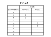
- FIG. 4A is a diagram showing an example of a random table when the shift position is D, which indicates forward movement.
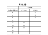
- FIG. 4B is a diagram showing an example of a random table when the shift position is R, which indicates reverse.
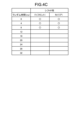
- FIG. 4C is a diagram showing an example of a random table when the shift position is P, which indicates parking.
- FIG. 5 is a flowchart showing an example of a procedure of ultrasonic wave transmission processing according to this embodiment.
- FIG. 6 is a diagram showing an example of ultrasonic transmission timings shifted by a random time in a conventional object detection device.
- FIG. 7 is a diagram showing an example of ultrasonic transmission timings
- FIG. 1 is a top view showing an example of the configuration of a vehicle 1 according to an embodiment.
- the vehicle 1 is an example of a moving body on which an object detection device according to this embodiment is mounted.
- the object detection device according to this embodiment is a device that detects objects present around the vehicle 1 based on information such as TOF (Time Of Flight) and Doppler shift obtained by transmitting a transmission wave from the vehicle 1 and receiving a reception wave (reflected wave) generated when the transmission wave is reflected by an object.
- TOF Time Of Flight
- Doppler shift obtained by transmitting a transmission wave from the vehicle 1 and receiving a reception wave (reflected wave) generated when the transmission wave is reflected by an object.
- the object detection device is connected to multiple transceivers 21A to 21L.
- transceiver 21 when there is no need to distinguish between the multiple transceivers 21A to 21L, they will be referred to as transceiver 21.
- Each transceiver unit 21 is installed on the vehicle body 2, which is the exterior of the vehicle 1, and transmits ultrasonic waves (an example of a transmitted wave) toward the outside of the vehicle body 2, and receives reflected waves from objects outside the vehicle body 2 as received waves.
- ultrasonic waves an example of a transmitted wave
- four transceivers 21A-21D are arranged at the front end of the vehicle body 2
- four transceivers 21E-21H are arranged at the rear end
- two transceivers 21I, 21J are arranged on the right side
- two transceivers 21K, 21L are arranged on the left side. Note that the number and installation positions of the transceivers 21 are not limited to this example.
- FIG. 2 is a block diagram showing an example of the hardware configuration of a vehicle control system 50 according to an embodiment.
- the vehicle control system 50 performs processing for controlling the vehicle 1 based on information output from the transmission/reception unit 21.
- the vehicle control system 50 according to this embodiment mainly includes an ECU (Electronic Control Unit) 100, a plurality of transmission/reception units 21, a brake system 221, a buzzer 222, an engine 223, and a shift sensor 224.
- ECU Electronic Control Unit
- the ECU 100 and each transmitter/receiver 21 are connected by an in-vehicle network, LIN (Local Interconnect Network) 240.
- the ECU 100 and each of the brake system 221, buzzer 222, engine 223, and shift sensor 224 are connected by a in-vehicle network, CAN (Controller Area Network) 230.
- Each transmitter/receiver 21 includes a transducer 211 constructed using a piezoelectric element or the like, an amplifier, etc., and realizes transmission and reception of ultrasonic waves by the vibration of the transducer 211. Specifically, each transmitter/receiver 21 transmits ultrasonic waves generated in response to the vibration of the transducer 211 as a transmission wave, and detects the vibration of the transducer 211 caused by a reflected wave (received wave) of the transmission wave reflected by an object such as an obstacle O or a road surface RS.
- the vibration of the transducer 211 is converted into an electrical signal, and based on the electrical signal, it is possible to obtain TOF corresponding to the distance from the transmitter/receiver 21 to the obstacle O, Doppler shift information corresponding to the relative speed of the obstacle O, etc.
- a configuration is illustrated in which both the transmission of the transmission wave and the reception of the reception wave are performed using a single transducer 211, but the configuration of the transmitter/receiver 21 is not limited to this.
- the transmission side and the reception side may be separated, such as a configuration in which a transducer for transmitting the transmission wave and a transducer for receiving the reception wave are separately provided.
- ECU 100 is a unit that executes various processes for controlling vehicle 1 based on various information. By sending control signals via CAN 230, ECU 100 can control brake system 221, engine 223, etc., and output sound to buzzer 222. ECU 100 can also receive detection results from shift sensor 224, etc., via CAN 230.
- the ECU 100 includes a CPU (Central Processing Unit) 130, a SSD (Solid State Drive) 121, a ROM (Read Only Memory) 122, and a RAM (Random Access Memory) 123.
- the ECU 100 is an example of an object detection device.
- the ECU 100 may also be referred to as an object detection device 100.
- the CPU 130 can execute various types of calculation processing and control, such as outputting an alarm to the buzzer 222, detecting objects, and determining whether or not there is interference with an object.
- the ROM 122 is a non-volatile storage device. Programs are stored in the ROM 122 in advance. The CPU 130 can read out the programs stored in the ROM 122 and execute calculation processing in accordance with the programs.
- SSD 121 is a rewritable non-volatile storage unit, and can store data even when the power of ECU 100 is turned off.
- CPU 130, ROM 122, RAM 123, etc. can be integrated in the same package.
- ECU 100 may be configured to use other logical calculation processors such as DSP (Digital Signal Processor) or logical circuits instead of CPU 130.
- HDD Hard Disk Drive
- SSD 121 and HDD may be provided separately from ECU 100.
- the brake system 221 may be, for example, an ABS (Anti-lock Brake System) that prevents the brakes from locking, an electronic stability control (ESC) that prevents the vehicle 1 from skidding when cornering, an electric brake system that increases the braking force (performing brake assist), or a brake by wire (BBW).
- ABS Anti-lock Brake System
- ESC electronic stability control
- BBW brake by wire
- the engine 223 is a prime mover that drives the vehicle 1 .
- the buzzer 222 is provided inside the vehicle 1 and outputs an alarm.
- the shift sensor 224 detects the shift position, which is the position of a shift lever that switches the transmission of the vehicle 1 , and notifies the ECU 100 of the shift position.
- Fig. 3 is a block diagram showing an example of a functional configuration of the object detection device 100 according to this embodiment.
- the object detection device 100 according to this embodiment has a functional configuration mainly including a sound wave control unit 150, a vehicle state estimation unit 160, a notification control unit 162, a vehicle information management unit 163, and a braking control unit 164.
- the vehicle state estimation unit 160 estimates various states of the vehicle 1 .
- the notification control unit 162 issues a notification by outputting an alarm from the buzzer 222 when the vehicle 1 is approaching an object, i.e., when a detection distance calculation unit 1521 (described later) determines that the distance to the object is equal to or shorter than a predetermined distance based on ultrasonic waves transmitted and received by the transmission/reception unit 21, the abnormality detection unit 1522 (described later).
- the vehicle information management unit 163 manages various information of the vehicle 1.
- the braking control unit 164 controls braking by the brake system 221.
- the ultrasonic wave control unit 150 controls the transmission of ultrasonic waves by the transmitting/receiving unit 21 and manages information based on the reflected waves received by the transmitting/receiving unit 21. As shown in FIG. 3, the ultrasonic wave control unit 150 includes a transmitting/receiving control unit 1510 and a transmitting/receiving information management unit 1520.
- the transmission/reception control unit 1510 controls the transmission and reception of ultrasonic waves by the transmission/reception unit 21. As shown in FIG. 3, the transmission/reception control unit 1510 includes a wave transmission control unit 1511, a random time determination unit 1512, and a random table 1513.
- the wave transmission control unit 1511 controls the transmitting/receiving unit to transmit ultrasonic waves at a predetermined transmission timing. More specifically, the wave transmission control unit 1511 controls the transmitting/receiving unit 21 to transmit ultrasonic waves at a new transmission timing that is delayed by a random time determined by a random time determination unit 1512 described below.
- the random time is a waiting time for shifting the transmission timing of the ultrasonic waves.
- the wave transmission control unit 1511 is an example of a control unit.
- the random time determination unit 1512 inputs the shift position detected by the shift sensor 224 from the shift sensor 224. The random time determination unit 1512 then determines a random time according to the input shift position.
- the random time determination unit 1512 is an example of a determination unit.
- the random time determination unit 1512 refers to the random table 1513 and determines different times for the random time of ultrasonic waves as transmission waves from the transceivers 21A to 21D provided at the front of the vehicle 1 and the random time of ultrasonic waves from the transceivers 21E to 21H provided at the rear of the vehicle 1, depending on the shift position.
- the random table 1513 is stored in a storage medium such as the SSD 121.
- the random table 1513 determines, for each shift position, the random time of the transmission waves from the transceivers 21A to 21D provided at the front of the vehicle 1 (an example of a first random time) and the random time of the transmission waves from the transceivers 21E to 21H provided at the rear of the vehicle 1 (an example of a second random time).
- FIGS. 4A to 4C are diagrams showing an example of a random table according to this embodiment.
- FIG. 4A is a diagram showing an example of a random table when the shift position is D, indicating forward movement.
- FIG. 4B is a diagram showing an example of a random table when the shift position is R, indicating reverse movement.
- FIG. 4C is a diagram showing an example of a random table when the shift position is P, indicating parking.
- the random time for Fr is the random time (first random time) of the transmission waves (i.e., ultrasound) from the transceivers 21A to 21D provided at the front of the vehicle 1
- the random time for Rr (rear) is the random time (second random time) of the transmission waves (i.e., ultrasound) from the transceivers 21E to 21H provided at the rear of the vehicle 1.
- three random times are set for each, and any random time can be selected from these.
- the random time of Fr (first random time) is set to be shorter than the random time of Rr.
- the random time of Fr (first random time) is set to be longer than the random time of Rr.
- the random time determination unit 1512 therefore refers to the random table 1513 and determines the random time of Fr and the random time of Rr when the shift position is D, which indicates forward movement, so that the random time of the transmission waves from the Fr transceiver unit 21, i.e., the transceiver units 21A-21D provided at the front of the vehicle 1, is shorter than the random time of the transmission waves from the Rr transceiver unit 21, i.e., the transceiver units 21E-21H provided at the rear of the vehicle 1.
- the random time determination unit 1512 also refers to the random table 1513 to determine the random time of Fr and the random time of Rr when the shift position is R, which indicates reverse gear, so that the random time of the transmission waves from the Fr transceiver unit 21, i.e., the transceiver units 21A-21D provided at the front of the vehicle 1, is longer than the random time of the transmission waves from the Rr transceiver unit 21, i.e., the transceiver units 21E-21H provided at the rear of the vehicle 1.
- the transmission/reception information management unit 1520 manages information based on the reflected waves received by the transmission/reception unit 21. As shown in FIG. 3, the transmission/reception information management unit 1520 includes a detection distance calculation unit 1521 and an abnormality detection unit 1522.
- the detection distance calculation unit 1521 calculates the distance to the object based on the transmitted wave sent by the transceiver unit 21 and the reflected wave received.
- a publicly known method is used to calculate the distance.
- the abnormality detection unit 1522 detects abnormalities in the vehicle 1, etc. In this embodiment, the abnormality detection unit 1522 determines that an object is approaching if the distance calculated by the detection distance calculation unit 1521 is equal to or less than a predetermined distance. The abnormality detection unit 1522 also detects whether or not ultrasonic waves are interfering based on the distance calculated by the detection distance calculation unit 1521. For example, if the abnormality detection unit 1522 detects that the distance calculated by the detection distance calculation unit 1521 is equal to or less than a predetermined threshold three times in a row, it determines that ultrasonic waves are interfering. Note that the method of detecting ultrasonic interference is not limited to this.
- 5 is a flowchart showing an example of the procedure of the ultrasonic wave transmission process according to this embodiment. This transmission process is performed when the vehicle 1 starts traveling and each time a gear shift is detected by the shift sensor 224.
- the random time determination unit 1512 obtains the current shift position from the shift sensor 224 (S11). Then, the random time determination unit 1512 determines whether the shift position is D or not (S12). If the shift position is D (S12: Yes), the random time determination unit 1512 selects the random table for shift D shown in FIG. 4A as the random table for Fr (front) and Rr (rear) (S13).
- the random time determination unit 1512 determines whether the shift position is R or not (S14). If the shift position is R (S14: Yes), the random time determination unit 1512 selects the random table for shift R shown in FIG. 4B as the random table for Fr (front) and Rr (rear) (S15).
- the random time determination unit 1512 determines whether the shift position is P or not (S16). If the shift position is P (S16: Yes), the random time determination unit 1512 selects the random table for shift P shown in FIG. 4C as the random table for Fr (front) and Rr (rear) (S17).
- the random time determination unit 1512 selects the random table corresponding to the previous shift position as the random table for Fr (front) and Rr (rear) (S18).
- the random time determination unit 1512 obtains and determines the random time set in the selected random table (S19).
- the wave transmission control unit 1511 controls the transceiver unit 21 to transmit ultrasound at a timing shifted by the random time determined in S19, causing the transceiver unit 21 to transmit ultrasound at a timing shifted by the random time (S20).
- a vehicle would transmit ultrasonic waves to detect an object, and if the distance to the object is close and less than a specified distance, a warning would be issued from a buzzer.
- the timing of transmitting ultrasonic waves is in a certain relationship between the vehicle and another vehicle, when the vehicle receives ultrasonic waves transmitted by the other vehicle, the ultrasonic waves may be mistakenly recognized as a reflected wave of the ultrasonic waves transmitted by the vehicle, resulting in so-called interference.
- the vehicle and another vehicle transmit ultrasonic waves at the same time, the vehicle will mistakenly recognize the ultrasonic waves returning from half the distance as a reflected wave. For this reason, if an object is close and is mistakenly recognized as being within the range of the buzzer output, this will lead to an erroneous buzzer output.
- conventional object detection devices have a technique of determining that interference is occurring if they detect the same distance continuously above a certain threshold. For example, an object detection device will determine that interference is occurring if it detects a distance of 30 cm three times in succession. If interference is determined to be occurring, the object detection device can avoid continuous detection of the same distance by shifting the timing of transmitting ultrasonic waves.
- FIGs 6 and 7 are diagrams showing an example of ultrasonic transmission timing shifted by a random time in a conventional object detection device.
- ultrasonic waves are transmitted at intervals of 168 ms, but if it is determined that there is interference, the object detection device can avoid interference by transmitting ultrasonic waves every 172 ms, shifting the transmission time by a random time of 4 ms.
- the random time determination unit 1512 determines a random time, which is a waiting time for shifting the transmission timing, according to the shift position, which is the position of the shift lever that switches the transmission of the vehicle 1, and the wave transmission control unit 1511 controls the transceiver unit 21 to transmit ultrasonic waves at a new transmission timing that is delayed by the determined random time. Therefore, according to this embodiment, even if another vehicle is equipped with the same object detection device as the host vehicle, the random time is delayed according to the shift position, making it possible to reliably avoid ultrasonic wave interference.
- the random time determination unit 1512 determines the random time of the ultrasonic waves from the transceivers 21A-21D provided at the front of the vehicle 1 to be different from the random time of the ultrasonic waves from the transceivers 21E-21H provided at the rear of the vehicle 1. Therefore, according to this embodiment, even if another vehicle is equipped with the same object detection device as the host vehicle, and further, because the random time of the transceivers 21A-21D at the front of the vehicle 1 differs from the random time of the transceivers 21E-21H at the rear of the vehicle 1, it is possible to more reliably avoid ultrasonic interference even when the host vehicle is following another vehicle.
- the random time determination unit 1512 determines the random time of Fr (front) and the random time of Rr such that the random time of Fr (front), i.e., the random time of ultrasonic waves from the transmitting/receiving unit 21 provided at the front of the vehicle 1 (first random time), is shorter than the random time of Rr (rear), i.e., the random time of ultrasonic waves from the transmitting/receiving unit 21 provided at the rear of the vehicle 1 (second random time).
- the random time of Fr is shorter than the random time of Rr, so that the timing of transmitting ultrasonic waves at Fr is earlier than the timing of transmitting ultrasonic waves at Rr, making it possible to perform object detection with higher accuracy and reliably avoid ultrasonic interference.
- the random time determination unit 1512 further determines the random time of Fr and the random time of Rr when the shift position is R, which indicates reverse driving, so that the random time of Fr (front), i.e., the random time of ultrasonic waves from the transceiver unit 21 provided at the front of the vehicle 1 (first random time), is longer than the random time of Rr (rear), i.e., the random time of ultrasonic waves from the transceiver unit 21 provided at the rear of the vehicle 1 (second random time).
- the random time of Fr is longer than the random time of Rr, so that the timing of transmitting ultrasonic waves at Rr is earlier than the timing of transmitting ultrasonic waves at Fr, making it possible to perform object detection with higher accuracy and reliably avoid ultrasonic wave interference.
- this embodiment includes an SSD 121 that stores a random table 1513 in which the random time of Fr and the random time of Rr are determined for each shift position, and the random time determination unit 1512 determines the random time of Fr and the random time of Rr based on the shift position and the random table 1513. Therefore, according to this embodiment, the random time can be determined by switching the random table, making it possible to easily and reliably avoid ultrasonic interference.
- the CPU 130 reads and executes a program stored in a storage device such as the ROM 122 or the SSD 121, thereby realizing various functional modules such as the wave transmission control unit 1511, the random time determination unit 1512, the detection distance calculation unit 1521, the abnormality detection unit 1522, the vehicle state estimation unit 160, the notification control unit 162, the vehicle information management unit 163, and the braking control unit 164.
- various functional modules such as the wave transmission control unit 1511, the random time determination unit 1512, the detection distance calculation unit 1521, the abnormality detection unit 1522, the vehicle state estimation unit 160, the notification control unit 162, the vehicle information management unit 163, and the braking control unit 164 can also be realized by independent hardware.
- the object detection program executed by the object detection device 100 of the above embodiment is provided in advance in a ROM or the like.
- the object detection program executed by the object detection device 100 of the above embodiment may be configured to be provided by being recorded in an installable or executable file format on a computer-readable recording medium such as a CD-ROM, a flexible disk (FD), a CD-R, or a DVD (Digital Versatile Disk).
- a computer-readable recording medium such as a CD-ROM, a flexible disk (FD), a CD-R, or a DVD (Digital Versatile Disk).
- the object detection program executed by the object detection device 100 of the above embodiment may be configured to be stored on a computer connected to a network such as the Internet and provided by being downloaded via the network. Also, the object detection program executed by the object detection device 100 of the above embodiment may be configured to be provided or distributed via a network such as the Internet.
- the object detection program executed by the object detection device 100 of the above embodiment has a modular configuration including the above-mentioned units (wave transmission control unit 1511, random time determination unit 1512, detection distance calculation unit 1521, abnormality detection unit 1522, vehicle state estimation unit 160, notification control unit 162, vehicle information management unit 163, braking control unit 164, etc.), and in terms of actual hardware, the CPU reads out the object detection program from the above-mentioned ROM and executes it, loading the above-mentioned units onto the main storage device, and the wave transmission control unit 1511, random time determination unit 1512, detection distance calculation unit 1521, abnormality detection unit 1522, vehicle state estimation unit 160, notification control unit 162, vehicle information management unit 163, braking control unit 164, etc. are generated on the main storage device.
- the above-mentioned units wave transmission control unit 1511, random time determination unit 1512, detection distance calculation unit 1521, abnormality detection unit 1522, vehicle state estimation unit 160, notification control unit 162, vehicle information management unit 163, braking control unit
- the object detection device (100) of this embodiment has at least the following configuration. That is, the object detection device (100) An object detection device (100) mounted on a vehicle (1) and detecting an object present in the vicinity of the vehicle (1), a control unit (1511) that controls a transmitting/receiving unit (21) that transmits a transmission wave and receives a reception wave generated by the transmission wave being reflected by the object to transmit the transmission wave at a predetermined transmission timing; a determination unit (1512) that determines a random time, which is a waiting time for shifting the transmission timing, in accordance with a shift position, which is a position of a shift lever for switching a transmission of the vehicle (1); The control unit (1511) controls the transmitting/receiving unit (21) to transmit the transmission wave at a new transmission timing obtained by delaying the transmission timing by the determined random time.
- this configuration makes it possible to reliably avoid ultrasonic interference even if another vehicle is equipped with the same object detection device (100) as the vehicle itself, by delaying the random time according to the shift position.
- the determination unit (1512) determines the random time of the transmission wave from the transceiver unit (21) provided at the front of the vehicle (1) to be different from the random time of the transmission wave from the transceiver unit (21) provided at the rear of the vehicle (1).
- the determination unit (1512) determines the first random time and the second random time so that, when the shift position indicates forward movement, the first random time, which is the random time of the transmission wave from the transceiver unit (21) provided at the front of the vehicle (1), is shorter than the second random time, which is the random time of the transmission wave from the transceiver unit (21) provided at the rear of the vehicle (1).
- this configuration makes it possible to perform object detection with higher accuracy while reliably avoiding ultrasonic interference when the vehicle is moving forward.
- the determination unit (1512) further determines the first random time and the second random time such that the first random time is longer than the second random time when the shift position indicates reverse.
- the object detection device (100) of the embodiment further includes a storage unit (121) that stores random information (1513) in which the first random time and the second random time are determined for each shift position, The determination unit (1512) determines the first random time and the second random time based on the shift position and the random information (1513).
- This configuration for example, makes it possible to easily and reliably avoid ultrasonic interference.
- Vehicle 21 Transmitter/receiver 50 Vehicle control system 100 Object detection device (ECU) 121 SSD 211 Transducer 150 Sound wave control unit 1510 Transmission/reception control unit 1511 Wave transmission control unit 1512 Random time determination unit 1513 Random table 1520 Transmission/reception information management unit 1521 Detection distance calculation unit 1522 Abnormality detection unit 160 Vehicle state estimation unit 162 Notification control unit 163 Vehicle information management unit 164 Braking control unit
Landscapes
- Engineering & Computer Science (AREA)
- Radar, Positioning & Navigation (AREA)
- Remote Sensing (AREA)
- Physics & Mathematics (AREA)
- Computer Networks & Wireless Communication (AREA)
- General Physics & Mathematics (AREA)
- Acoustics & Sound (AREA)
- Measurement Of Velocity Or Position Using Acoustic Or Ultrasonic Waves (AREA)
Abstract
Description
ブザー222は、車両1の内部に設けられ、警報を出力する。
シフトセンサ224は、車両1のトランスミッションを切り替えるシフトレバーの位置であるシフト位置を検出し、ECU100に通知する。
図3は、本実施形態にかかる物体検出装置100の機能的構成の一例を示すブロック図である。本実施形態にかかる物体検出装置100は、図3に示すように、音波制御部150と、車両状態推定部160と、報知制御部162と、車両情報管理部163と、制動制御部164と、を主に備えた機能的構成となっている。
報知制御部162は、車両1が物体に接近している場合、すなわち、後述する検知距離算出部1521により送受信部21で送受信する超音波に基づいて物体との距離が,後述する異常検出部1522により所定距離以下となったと判断された場合に、ブザー222から警報を出力させることで報知する。車両情報管理部163は、車両1の各種情報を管理する。制動制御部164は、ブレーキシステム221による制動を制御する。
図5は、本実施形態にかかる超音波の送信処理の手順の一例を示すフローチャートである。この送信処理は、車両1の走行開始から実施し、またシフトセンサ224によりシフトチェンジが検知されるごとに実行される。
本実施形態の物体検出装置(100)は、以下の構成を少なくとも備える。
すなわち、物体検出装置(100)は、
車両(1)に搭載され、前記車両(1)の周辺に存在する物体を検出する物体検出装置(100)であって、
送信波を送信し、前記送信波が前記物体に反射されることにより生じる受信波を受信する送受信部(21)に対して、所定の送信タイミングで前記送信波を送信させる制御を行う制御部(1511)と、
前記車両(1)のトランスミッションを切り替えるシフトレバーの位置であるシフト位置に応じて、前記送信タイミングをずらすための待ち時間であるランダム時間を決定する決定部(1512)と、を備え、
前記制御部(1511)は、前記送信タイミングを、決定された前記ランダム時間だけ遅らせた新たな送信タイミングで、前記送信波を送信するように前記送受信部(21)を制御する。
前記決定部(1512)は、前記シフト位置と前記ランダム情報(1513)とに基づいて、前記第1のランダム時間および前記第2のランダム時間を決定する。
21 送受信部
50 車両制御システム
100 物体検出装置(ECU)
121 SSD
211 振動子
150 音波制御部
1510 送受信制御部
1511 送波制御部
1512 ランダム時間決定部
1513 ランダムテーブル
1520 送受信情報管理部
1521 検知距離算出部
1522 異常検出部
160 車両状態推定部
162 報知制御部
163 車両情報管理部
164 制動制御部
Claims (5)
- 車両に搭載され、前記車両の周辺に存在する物体を検出する物体検出装置であって、
送信波を送信し、前記送信波が前記物体に反射されることにより生じる受信波を受信する送受信部に対して、所定の送信タイミングで前記送信波を送信させる制御を行う制御部と、
前記車両のトランスミッションを切り替えるシフトレバーの位置であるシフト位置に応じて、前記送信タイミングをずらすための待ち時間であるランダム時間を決定する決定部と、を備え、
前記制御部は、前記送信タイミングを、決定された前記ランダム時間だけ遅らせた新たな送信タイミングで、前記送信波を送信するように前記送受信部を制御する、
物体検出装置。 - 前記決定部は、前記車両の前部に設けられた前記送受信部からの前記送信波のランダム時間と、前記車両の後部に設けられた前記送受信部からの前記送信波のランダム時間と、を異なる時間に決定する、
請求項1に記載の物体検出装置。 - 前記決定部は、前記シフト位置が前進を示す場合には、前記車両の前部に設けられた前記送受信部からの前記送信波のランダム時間である第1のランダム時間が、前記車両の後部に設けられた前記送受信部からの前記送信波のランダム時間である第2のランダム時間よりも短くなるように、前記第1のランダム時間および前記第2のランダム時間を決定する、
請求項2に記載の物体検出装置。 - 前記決定部は、さらに、前記シフト位置が後退を示す場合には、前記第1のランダム時間が、前記第2のランダム時間よりも長くなるように、前記第1のランダム時間および前記第2のランダム時間を決定する、
請求項3に記載の物体検出装置。 - 前記シフト位置ごとに、前記第1のランダム時間と、前記第2のランダム時間とが定められたランダム情報を記憶する記憶部、をさらに備え、
前記決定部は、前記シフト位置と前記ランダム情報とに基づいて、前記第1のランダム時間および前記第2のランダム時間を決定する、
請求項4に記載の物体検出装置。
Priority Applications (3)
| Application Number | Priority Date | Filing Date | Title |
|---|---|---|---|
| US19/116,121 US20260104496A1 (en) | 2022-09-30 | 2023-09-28 | Object detection device |
| CN202380068565.0A CN119948358A (zh) | 2022-09-30 | 2023-09-28 | 物体检测装置 |
| EP23872555.0A EP4597165A4 (en) | 2022-09-30 | 2023-09-28 | OBJECT DETECTION DEVICE |
Applications Claiming Priority (2)
| Application Number | Priority Date | Filing Date | Title |
|---|---|---|---|
| JP2022-157358 | 2022-09-30 | ||
| JP2022157358A JP7825536B2 (ja) | 2022-09-30 | 2022-09-30 | 物体検出装置 |
Publications (1)
| Publication Number | Publication Date |
|---|---|
| WO2024071335A1 true WO2024071335A1 (ja) | 2024-04-04 |
Family
ID=90478113
Family Applications (1)
| Application Number | Title | Priority Date | Filing Date |
|---|---|---|---|
| PCT/JP2023/035510 Ceased WO2024071335A1 (ja) | 2022-09-30 | 2023-09-28 | 物体検出装置 |
Country Status (5)
| Country | Link |
|---|---|
| US (1) | US20260104496A1 (ja) |
| EP (1) | EP4597165A4 (ja) |
| JP (1) | JP7825536B2 (ja) |
| CN (1) | CN119948358A (ja) |
| WO (1) | WO2024071335A1 (ja) |
Citations (5)
| Publication number | Priority date | Publication date | Assignee | Title |
|---|---|---|---|---|
| JP2003302462A (ja) * | 2002-04-11 | 2003-10-24 | Denso Corp | レーダ装置,レーダ用信号処理装置,プログラム |
| US20040130482A1 (en) * | 2003-01-02 | 2004-07-08 | Yu-Shan Lin | Digital controlled linear sweep frequency mode for FMCW radar altimeter |
| JP2018059827A (ja) * | 2016-10-06 | 2018-04-12 | 京セラ株式会社 | 測距装置、測距方法及び車両 |
| JP2018059826A (ja) | 2016-10-06 | 2018-04-12 | 京セラ株式会社 | 測距装置、車両及び測距方法 |
| JP6413620B2 (ja) | 2014-10-22 | 2018-10-31 | 株式会社Soken | 物体検出装置 |
-
2022
- 2022-09-30 JP JP2022157358A patent/JP7825536B2/ja active Active
-
2023
- 2023-09-28 US US19/116,121 patent/US20260104496A1/en active Pending
- 2023-09-28 WO PCT/JP2023/035510 patent/WO2024071335A1/ja not_active Ceased
- 2023-09-28 EP EP23872555.0A patent/EP4597165A4/en active Pending
- 2023-09-28 CN CN202380068565.0A patent/CN119948358A/zh active Pending
Patent Citations (5)
| Publication number | Priority date | Publication date | Assignee | Title |
|---|---|---|---|---|
| JP2003302462A (ja) * | 2002-04-11 | 2003-10-24 | Denso Corp | レーダ装置,レーダ用信号処理装置,プログラム |
| US20040130482A1 (en) * | 2003-01-02 | 2004-07-08 | Yu-Shan Lin | Digital controlled linear sweep frequency mode for FMCW radar altimeter |
| JP6413620B2 (ja) | 2014-10-22 | 2018-10-31 | 株式会社Soken | 物体検出装置 |
| JP2018059827A (ja) * | 2016-10-06 | 2018-04-12 | 京セラ株式会社 | 測距装置、測距方法及び車両 |
| JP2018059826A (ja) | 2016-10-06 | 2018-04-12 | 京セラ株式会社 | 測距装置、車両及び測距方法 |
Non-Patent Citations (1)
| Title |
|---|
| See also references of EP4597165A4 |
Also Published As
| Publication number | Publication date |
|---|---|
| EP4597165A1 (en) | 2025-08-06 |
| EP4597165A4 (en) | 2026-01-14 |
| JP7825536B2 (ja) | 2026-03-06 |
| JP2024051284A (ja) | 2024-04-11 |
| CN119948358A (zh) | 2025-05-06 |
| US20260104496A1 (en) | 2026-04-16 |
Similar Documents
| Publication | Publication Date | Title |
|---|---|---|
| JP6293901B2 (ja) | 自動車の超音波センサの受信信号における標的エコーを検知する方法、超音波センサ装置および自動車 | |
| CN107110960B (zh) | 物体检测装置 | |
| JP3944022B2 (ja) | 車両の走行制御装置 | |
| WO2013136495A1 (ja) | 車両走行制御装置 | |
| CN106662642A (zh) | 检测系统 | |
| JP4824511B2 (ja) | 車両の走行安全装置 | |
| JP7825536B2 (ja) | 物体検出装置 | |
| JP7752587B2 (ja) | 物体検出装置 | |
| JP4950959B2 (ja) | 車両走行支援装置 | |
| US11999353B2 (en) | Detection device for detecting road surface information related to movable body and control thereof | |
| JP7714275B2 (ja) | 障害物検知装置、障害物検知方法及びプログラム | |
| KR20220052616A (ko) | 운전자 보조 장치, 차량 및 그 제어 방법 | |
| US20240151847A1 (en) | Object detection device | |
| JP7397191B2 (ja) | 物体の分類態様に応じて伝送信号を適合させる車両の距離センサの動作方法、演算デバイス、およびセンサデバイス | |
| JP6242702B2 (ja) | 自動制動制御装置 | |
| JP2024143931A (ja) | 物体検出装置、車両および物体検出方法 | |
| JP2024130468A (ja) | 障害物検知装置、障害物検知方法およびプログラム | |
| US20250044433A1 (en) | Object detection device | |
| JP2024054675A (ja) | 物体検出システム | |
| JP7721906B2 (ja) | 物体検出装置及び移動体制御装置 | |
| US12517246B2 (en) | Object detection device | |
| JP7547853B2 (ja) | 物体検出装置 | |
| US20220297684A1 (en) | Driving support apparatus, driving support method, and computer-readable medium | |
| JP2025030177A (ja) | 物体検出装置 | |
| JP2025062286A (ja) | 物体検出装置 |
Legal Events
| Date | Code | Title | Description |
|---|---|---|---|
| 121 | Ep: the epo has been informed by wipo that ep was designated in this application |
Ref document number: 23872555 Country of ref document: EP Kind code of ref document: A1 |
|
| WWE | Wipo information: entry into national phase |
Ref document number: 202380068565.0 Country of ref document: CN |
|
| WWE | Wipo information: entry into national phase |
Ref document number: 2023872555 Country of ref document: EP |
|
| NENP | Non-entry into the national phase |
Ref country code: DE |
|
| ENP | Entry into the national phase |
Ref document number: 2023872555 Country of ref document: EP Effective date: 20250430 |
|
| WWP | Wipo information: published in national office |
Ref document number: 202380068565.0 Country of ref document: CN |
|
| WWP | Wipo information: published in national office |
Ref document number: 2023872555 Country of ref document: EP |