WO2024080006A1 - システム - Google Patents
システム Download PDFInfo
- Publication number
- WO2024080006A1 WO2024080006A1 PCT/JP2023/030617 JP2023030617W WO2024080006A1 WO 2024080006 A1 WO2024080006 A1 WO 2024080006A1 JP 2023030617 W JP2023030617 W JP 2023030617W WO 2024080006 A1 WO2024080006 A1 WO 2024080006A1
- Authority
- WO
- WIPO (PCT)
- Prior art keywords
- switching units
- battery pack
- battery packs
- discharge
- management unit
- Prior art date
- Legal status (The legal status is an assumption and is not a legal conclusion. Google has not performed a legal analysis and makes no representation as to the accuracy of the status listed.)
- Ceased
Links
Images


Classifications
-
- H—ELECTRICITY
- H02—GENERATION; CONVERSION OR DISTRIBUTION OF ELECTRIC POWER
- H02J—ELECTRIC POWER NETWORKS; CIRCUIT ARRANGEMENTS OR SYSTEMS FOR SUPPLYING OR DISTRIBUTING ELECTRIC POWER; SYSTEMS FOR STORING ELECTRIC ENERGY
- H02J7/00—Circuit arrangements for charging or discharging batteries or for supplying loads from batteries
- H02J7/34—Parallel operation in networks using both storage and other DC sources, e.g. providing buffering
- H02J7/35—Parallel operation in networks using both storage and other DC sources, e.g. providing buffering with light sensitive cells
-
- H—ELECTRICITY
- H02—GENERATION; CONVERSION OR DISTRIBUTION OF ELECTRIC POWER
- H02J—ELECTRIC POWER NETWORKS; CIRCUIT ARRANGEMENTS OR SYSTEMS FOR SUPPLYING OR DISTRIBUTING ELECTRIC POWER; SYSTEMS FOR STORING ELECTRIC ENERGY
- H02J7/00—Circuit arrangements for charging or discharging batteries or for supplying loads from batteries
- H02J7/50—Circuit arrangements for charging or discharging batteries or for supplying loads from batteries acting upon multiple batteries simultaneously or sequentially
- H02J7/52—Circuit arrangements for charging or discharging batteries or for supplying loads from batteries acting upon multiple batteries simultaneously or sequentially for charge balancing, e.g. equalisation of charge between batteries
- H02J7/56—Active balancing, e.g. using capacitor-based, inductor-based or DC-DC converters
-
- B—PERFORMING OPERATIONS; TRANSPORTING
- B64—AIRCRAFT; AVIATION; COSMONAUTICS
- B64D—EQUIPMENT FOR FITTING IN OR TO AIRCRAFT; FLIGHT SUITS; PARACHUTES; ARRANGEMENT OR MOUNTING OF POWER PLANTS OR PROPULSION TRANSMISSIONS IN AIRCRAFT
- B64D27/00—Arrangement or mounting of power plants in aircraft; Aircraft characterised by the type or position of power plants
- B64D27/02—Aircraft characterised by the type or position of power plants
- B64D27/24—Aircraft characterised by the type or position of power plants using steam or spring force
-
- H—ELECTRICITY
- H02—GENERATION; CONVERSION OR DISTRIBUTION OF ELECTRIC POWER
- H02J—ELECTRIC POWER NETWORKS; CIRCUIT ARRANGEMENTS OR SYSTEMS FOR SUPPLYING OR DISTRIBUTING ELECTRIC POWER; SYSTEMS FOR STORING ELECTRIC ENERGY
- H02J7/00—Circuit arrangements for charging or discharging batteries or for supplying loads from batteries
- H02J7/34—Parallel operation in networks using both storage and other DC sources, e.g. providing buffering
- H02J7/342—The other DC source being a battery actively interacting with the first one, i.e. battery to battery charging
-
- H—ELECTRICITY
- H02—GENERATION; CONVERSION OR DISTRIBUTION OF ELECTRIC POWER
- H02J—ELECTRIC POWER NETWORKS; CIRCUIT ARRANGEMENTS OR SYSTEMS FOR SUPPLYING OR DISTRIBUTING ELECTRIC POWER; SYSTEMS FOR STORING ELECTRIC ENERGY
- H02J7/00—Circuit arrangements for charging or discharging batteries or for supplying loads from batteries
- H02J7/60—Circuit arrangements for charging or discharging batteries or for supplying loads from batteries including safety or protection arrangements
- H02J7/64—Circuit arrangements for charging or discharging batteries or for supplying loads from batteries including safety or protection arrangements against overvoltage
-
- H—ELECTRICITY
- H02—GENERATION; CONVERSION OR DISTRIBUTION OF ELECTRIC POWER
- H02J—ELECTRIC POWER NETWORKS; CIRCUIT ARRANGEMENTS OR SYSTEMS FOR SUPPLYING OR DISTRIBUTING ELECTRIC POWER; SYSTEMS FOR STORING ELECTRIC ENERGY
- H02J7/00—Circuit arrangements for charging or discharging batteries or for supplying loads from batteries
- H02J7/60—Circuit arrangements for charging or discharging batteries or for supplying loads from batteries including safety or protection arrangements
- H02J7/663—Circuit arrangements for charging or discharging batteries or for supplying loads from batteries including safety or protection arrangements using battery or load disconnect circuits
-
- H—ELECTRICITY
- H02—GENERATION; CONVERSION OR DISTRIBUTION OF ELECTRIC POWER
- H02J—ELECTRIC POWER NETWORKS; CIRCUIT ARRANGEMENTS OR SYSTEMS FOR SUPPLYING OR DISTRIBUTING ELECTRIC POWER; SYSTEMS FOR STORING ELECTRIC ENERGY
- H02J7/00—Circuit arrangements for charging or discharging batteries or for supplying loads from batteries
- H02J7/865—Battery or charger load switching, e.g. concurrent charging and load supply
-
- H—ELECTRICITY
- H02—GENERATION; CONVERSION OR DISTRIBUTION OF ELECTRIC POWER
- H02J—ELECTRIC POWER NETWORKS; CIRCUIT ARRANGEMENTS OR SYSTEMS FOR SUPPLYING OR DISTRIBUTING ELECTRIC POWER; SYSTEMS FOR STORING ELECTRIC ENERGY
- H02J7/00—Circuit arrangements for charging or discharging batteries or for supplying loads from batteries
- H02J7/90—Regulation of charging or discharging current or voltage
- H02J7/96—Regulation of charging or discharging current or voltage in response to battery voltage
Definitions
- the present invention relates to a system.
- a system may include a plurality of switching units connected in parallel to a bus to which a power generation unit and a load are connected, each switching on and off the connection of a battery pack to the bus.
- the system may include a plurality of the battery packs connected to each of the plurality of switching units.
- the system may include a management unit that manages the plurality of switching units to alternately discharge the plurality of battery packs so that the discharge rate of each of the plurality of battery packs is higher than when all of the plurality of battery packs are discharged.
- At least one of the plurality of switching units may have a discharge FET and a charge FET that can switch between a discharge state in which a current flows from the connected battery pack to the bus, a charge state in which a current flows from the bus to the battery pack, and a disconnected state in which no current flows between the bus and the battery pack.
- some of the multiple switching units may have the discharge FET and the charge FET, and another of the multiple switching units may have a contactor connected to the bus and the discharge FET and the charge FET connected in series between the contactor and the battery pack.
- the management unit may maintain the contactors of the other part of the multiple switching units in an off state while a predetermined condition is satisfied.
- the management unit may maintain the contactors of the other part of the multiple switching units in an off state while the system is located in an area where lightning occurs.
- the management unit may maintain the contactors of the other part of the multiple switching units in an off state when a malfunction occurs in at least one of the discharge FET and the charge FET of the other part of the multiple switching units.
- the contactor may be of a type that turns off when a control current is applied, and the management unit may apply the control current to the contactor while the predetermined condition is satisfied.
- some of the multiple switching units may have the discharge FET and the charge FET, and other of the multiple switching units may have contactors that switch on and off a current between the connected battery pack and the bus.
- the management unit may, during charging, set the some of the multiple switching units to the charging state and turn on the contactors of the other part of the multiple switching units, and during discharging, turn on the contactors of the other part of the multiple switching units, and alternately set the some of the multiple switching units to the discharging state.
- the management unit may alternately set the some of the multiple switching units to the discharging state such that not all of the switching units are in the discharging state at the same time.
- all of the multiple switching units may have the discharge FET and the charge FET.
- all of the multiple switching units may have a contactor connected to the bus, and the discharge FET and the charge FET connected in series between the contactor and the battery pack.
- the management unit may maintain the contactors of some of the multiple switching units in an off state while a predetermined condition is satisfied.
- the management unit may turn on only the contactors of some of the multiple switching units and maintain the contactors of other of the multiple switching units in an off state while the system is located in an area where lightning occurs.
- the contactors of the multiple switching units may be of a type that turns off when a control current is applied, and the management unit may apply the control current to the contactors of the other of the multiple switching units while the system is located in an area where lightning occurs.
- the management unit may control the multiple switching units to alternately discharge the multiple battery packs so that the voltage difference between the battery pack with the highest voltage and the battery pack with the lowest voltage among the multiple battery packs does not exceed a voltage threshold.
- the management unit may control the multiple switching units so as to simultaneously charge the multiple battery packs with the power generated by the power generation unit.
- the system may be mounted on an aircraft, the multiple battery packs may be disposed on the wings of the aircraft, the power generation unit may perform solar power generation, and the load may be a motor that rotates a propeller of the aircraft.
- the system may include the aircraft.
- the aircraft may have a communication control unit that uses power discharged by the multiple battery packs to provide wireless communication services to user terminals within a communication area formed by irradiating a beam toward the ground.
- 1 illustrates a schematic diagram of an example of a system 10.
- 1 illustrates a schematic diagram of an example of a system 10.
- 1 shows a schematic diagram of an example of current flow during charging in the system 10.
- 1 shows a schematic diagram of an example of current flow during discharge in the system 10.
- 2 illustrates an example of a functional configuration of a management device 100.
- 3 shows another example of current flow during discharge in the system 10 .
- 2 illustrates an example of the configuration of a plurality of switching units 210.
- 13 shows another example of the configuration of the multiple switching units 210.
- 13 shows another example of the configuration of the multiple switching units 210.
- 2 shows an example of a configuration of a switching unit 210 including a contactor 214, a discharge FET, and a charge FET.
- An example of an airplane 600 equipped with the system 10 is shown diagrammatically. Another example of an airplane 600 equipped with the system 10 is shown diagrammatically. Another example of an airplane 600 equipped with the system 10 is shown diagrammatically. Another example of an airplane 600 equipped with the system 10 is shown diagrammatically. An example of a HAPS 700 incorporating the system 10 is shown generally. 1 illustrates an example of a hardware configuration of a computer 1200 that functions as the management device 100.
- Batteries (especially batteries using lithium metal anodes) have the characteristic that they deteriorate quickly when the discharge rate is low.
- a technique has been proposed in which multiple battery packs are used in alternation to increase the discharge rate per battery pack. Any switching unit can be used to switch the battery packs as long as it can turn the battery packs on and off, but since the characteristics differ depending on the unit used, it may be necessary to devise a method according to the characteristics.
- the system 10 according to this embodiment realizes switching control that takes such characteristics into account. Furthermore, the system 10 according to this embodiment realizes battery charge and discharge management that takes the above-mentioned battery characteristics into account.
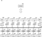
- FIG. 1 shows a schematic diagram of an example of a system 10.
- the system 10 includes a management device 100.
- the management device 100 manages a plurality of battery packs 200 connected in parallel to a bus 400 to which a plurality of power generation units 300 and a plurality of loads 500 are connected.
- the management device 100 may manage the charging and discharging of the plurality of battery packs 200.
- the system 10 may include a plurality of battery packs 200.
- the system 10 may include a plurality of power generation units 300.
- the system 10 may include a plurality of loads 500.
- the type of battery in the battery pack 200 may be any type.
- the battery pack 200 is, for example, a battery that uses lithium as the negative electrode.
- the battery pack 200 is, for example, a lithium ion battery.
- the battery pack 200 may have a lithium metal battery.
- the battery pack 200 includes a plurality of cells 202.
- the cells 202 may be, for example, battery cells that use metallic lithium as the negative electrode.
- the power generation unit 300 performs, for example, solar power generation.
- the power generation method used by the power generation unit 300 may be another power generation method.
- the battery pack 200 can be charged by the power generated by the power generation unit 300.
- Multiple power generation units 300 may be connected in parallel to the bus 400.
- the load 500 consumes power from the battery pack 200 or consumes power generated by the power generation unit 300.
- the load 500 may be any device that operates with power.
- the load 500 may be a device related to the flight of the aircraft, such as a propeller or elevator.
- the management device 100 may manage the charging and discharging of the multiple battery packs 200 so as to suppress deterioration of the multiple battery packs 200.
- each of the battery packs 200 is connected to the bus 400 via a switching unit 210 that switches the connection of the battery packs 200 to the bus 400 on and off.
- a plurality of switching units 210 are connected in parallel to the bus 400, and each of the plurality of switching units 210 is connected to each of the plurality of battery packs 200.
- a plurality of solar cells 310 are connected to the bus 400 via an MPPT (Maximum Power Point Tracking) 320.
- the solar cells 310 may be an example of a power generation unit 300.
- a plurality of loads 500 are connected to the bus 400 via a controller 510.
- a left load 500 arranged on the left side of the bus 400 and a right load 500 arranged on the right side of the bus 400 are illustrated.
- the battery packs 200 When describing the battery packs 200, they may be described from left to right as battery pack A, battery pack B, battery pack C, battery pack D, battery pack E, battery pack F, battery pack G, and battery pack H.
- the switching units 210 When describing the switching units 210, they may be described from left to right as switching unit A, switching unit B, switching unit C, switching unit D, switching unit E, switching unit F, switching unit G, and switching unit E.
- FIG. 3 shows a schematic example of a current flow during charging in the system 10.
- the management device 100 may control the electrical connection of the multiple battery packs 200 to the bus 400 so that the multiple battery packs 200 are simultaneously charged with power generated by the multiple solar cells 310.
- the management device 100 controls all of the switching units 210 so that all of the battery packs 200 are electrically connected to the bus 400.
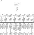
- FIG. 4 shows a schematic example of a current flow during discharging in the system 10.
- the management device 100 may control the multiple switching units 210 to alternately discharge the multiple battery packs 200 so that the discharge rate of each of the multiple battery packs 200 is higher than when all of the multiple battery packs 200 are discharging.
- the management device 100 controls the multiple switching units 210 to, for example, discharge the multiple battery packs 200 one by one in sequence.
- the management device 100 controls the multiple switching units 210 to, for example, repeatedly discharge the battery packs 200 in the order of battery pack A, battery pack B, battery pack C, battery pack D, battery pack E, battery pack F, battery pack G, and battery pack H.
- the management device 100 also controls the multiple switching units 210 to, for example, prioritize and sequentially discharge the battery packs 200 with higher voltages among the multiple battery packs 200. In this way, by discharging the eight battery packs 200 alternately, the discharge rate of the battery packs 200 can be increased by eight times compared to the case where all eight battery packs 200 are discharged.
- the management device 100 switches between charging and discharging the multiple battery packs 200 depending on the situation. For example, when all the battery packs 200 are electrically connected to the bus 400 for charging, if there is a large voltage difference between the battery pack 200 with the highest voltage and the battery pack 200 with the lowest voltage among the multiple battery packs 200, current will flow from the former to the latter, increasing the charging rate of the latter and possibly accelerating deterioration of the latter.
- the management device 100 may control the multiple switching units 210 to alternately discharge the multiple battery packs 200 so that the difference in remaining capacity between the battery pack 200 with the maximum remaining capacity and the battery pack 200 with the minimum remaining capacity among the multiple battery packs 200 does not exceed a predetermined voltage threshold.
- the management device 100 may control the multiple switching units 210 to alternately discharge the multiple battery packs 200 so that the difference in remaining capacity between the battery pack 200 with the maximum remaining capacity and the battery pack 200 with the minimum remaining capacity among the multiple battery packs 200 does not exceed a predetermined remaining capacity threshold.
- the management device 100 first starts discharging the battery pack 200 (sometimes referred to as the first battery pack 200) with the highest voltage among the multiple battery packs 200.
- the management device 100 starts discharging the second battery pack 200 before the difference between the voltage of the first battery pack 200 and the battery pack 200 (sometimes referred to as the second battery pack 200) with the highest voltage among the other multiple battery packs 200 among the multiple battery packs 200 becomes larger than the voltage threshold.
- the management device 100 stops discharging the first battery pack 200 after a predetermined time has elapsed since starting discharging the second battery pack 200. By repeating such control, it is possible to prevent the voltage difference between the battery pack 200 with the highest voltage and the battery pack 200 with the lowest voltage among the multiple battery packs 200 from becoming larger than a predetermined voltage threshold.
- the predetermined time may be, for example, about 0.01 to 1 second.
- FIG. 5 shows an example of the functional configuration of the management device 100.
- the management device 100 may include a management unit 110, a pack-related information acquisition unit 112, an estimation unit 114, and a receiving unit 116. Note that it is not essential that the management device 100 includes all of these.
- the management unit 110 controls the multiple switching units 210 to alternately discharge the multiple battery packs 200 so that the discharge rate of each of the multiple battery packs 200 is higher than when all of the multiple battery packs 200 are discharged.
- the management unit 110 may control the multiple switching units 210 to alternately discharge the multiple battery packs 200 so that the voltage difference between the battery pack 200 with the highest voltage and the battery pack 200 with the lowest voltage does not exceed a predetermined voltage threshold.
- the management unit 110 first starts discharging the battery pack 200 (sometimes referred to as the first battery pack 200) with the highest voltage among the multiple battery packs 200.
- the management unit 110 starts discharging the second battery pack 200 before the difference between the voltage of the first battery pack 200 and the battery pack 200 (sometimes referred to as the second battery pack 200) with the highest voltage among the other multiple battery packs 200 among the multiple battery packs 200 becomes greater than a predetermined voltage threshold.
- the management unit 110 stops discharging the first battery pack 200 after a predetermined time has elapsed since starting discharging the second battery pack 200.
- the management unit 110 repeats this control to sequentially discharge the multiple battery packs 200.
- the management unit 110 may control the electrical connection of the multiple battery packs 200 to the bus 400 so that the multiple battery packs 200 are simultaneously charged with power generated by the multiple solar cells 310.
- the management unit 110 controls the multiple switching units 210 so that the multiple battery packs 200 are simultaneously charged with power generated by the multiple solar cells 310.
- the management unit 110 may manage the voltage from the solar cells 310 to the bus 400 so that it is between the voltage of the battery pack 200 with the highest voltage among the multiple battery packs 200 and the voltage of the battery pack 200 with the lowest voltage.
- the management unit 110 may manage the voltage from the solar cells 310 to the bus 400 so that it is between the voltage of the battery pack 200 with the highest voltage among the multiple battery packs 200 and the voltage of the battery pack 200 with the lowest voltage by controlling the multiple MPPTs 320.
- the pack-related information acquisition unit 112 acquires pack-related information related to the battery pack 200 for each of the multiple battery packs 200. For example, the pack-related information acquisition unit 112 acquires information detected by a sensor disposed for each of the multiple battery packs 200 from the sensor as pack-related information.
- the pack-related information may include the OCV (Open Circuit Voltage) of the battery pack 200.
- the pack-related information may include the CCV (Closed Circuit Voltage) of the battery pack 200.
- the pack-related information may include the DCIR (Direct Current Internal Resistance) of the battery pack 200.
- the pack-related information may include the SOH (State of Health) of the battery pack 200.
- the pack-related information may include the SOC (State of Charge) of the battery pack 200.
- the pack-related information may include the current value of the battery pack 200.
- the pack-related information may include the discharge time of the battery pack 200.
- the pack-related information may include the integrated capacity of the battery pack 200.
- the pack-related information may include the temperature of the battery pack 200.
- the estimation unit 114 estimates the state of the battery pack 200 based on the pack-related information acquired by the pack-related information acquisition unit 112.
- the estimation unit 114 may perform the estimation using an estimation method used in an existing BMS (Battery Management System).
- the estimation unit 114 stores the relationship between the SOC and DCIR of the battery pack 200, and estimates the OCV of the battery pack 200 from the stored DCIR, SOH, current value, discharge time, CCV, and integrated capacity.
- the estimation unit 114 first estimates the SOC and SOH before the start of discharge from the OCV, current value, discharge time, CCV, integrated capacity, and temperature before the start of discharge. Next, the estimation unit 114 uses this data to estimate the current DCIR from a pre-stored database. The estimation unit 114 then estimates the current OCV from the estimated current DCIR, CCV, and current value.
- the management unit 110 may control the multiple switching units 210 to alternately discharge the multiple battery packs 200 based on the OCV of each of the multiple battery packs 200 acquired by the pack-related information acquisition unit 112, so that the voltage difference between the battery pack 200 with the highest voltage and the battery pack 200 with the lowest voltage among the multiple battery packs 200 does not exceed a predetermined voltage threshold.
- the management unit 110 may also control the multiple switching units 210 to alternately discharge the multiple battery packs 200 based on the OCVs of each of the multiple battery packs 200 estimated by the estimation unit 114, so that the voltage difference between the battery pack 200 with the highest voltage and the battery pack 200 with the lowest voltage among the multiple battery packs 200 does not exceed a predetermined voltage threshold.
- the management unit 110 may preset a voltage threshold such that the charging rate from the battery pack 200 with the highest voltage to the battery pack 200 with the lowest voltage does not become faster than a predetermined charging rate threshold.
- the charging rate threshold may be, for example, 0.3 C or less, and more preferably, 0.2 C or less.
- the management unit 110 starts the discharge of the second battery pack 200 with the next highest voltage (referred to as the second battery pack 200) before the voltage of the first battery pack 200 becomes lower than the voltage of the battery pack 200 with the next highest voltage by 6 V or more, and stops the discharge of the first battery pack 200 after a predetermined time has elapsed.
- the management unit 110 starts discharging the second battery pack 200 before the voltage of the first battery pack 200 becomes 9V or more lower than the voltage of the second battery pack 200, and stops discharging the first battery pack 200 after a predetermined time has elapsed.
- the management unit 110 may manage the consumption of the power generated by the solar cell 310 so that the charge rate at which the multiple battery packs 200 are charged does not exceed the charge rate threshold. For example, the management unit 110 controls the controller 510 so that the load 500 consumes the power generated by the solar cell 310 so that the charge rate at which the multiple battery packs 200 are charged by the power generated by the solar cell 310 does not exceed the charge rate threshold.
- the management unit 110 may manage the battery packs 200 so as to increase the power consumption of the battery pack 200 being discharged when the discharge rate of the battery pack 200 being discharged continues to be slower than a predetermined discharge rate threshold for a predetermined time.
- the management unit 110 controls the controller 510 so that the load 500 consumes the power of the battery pack 200.
- the predetermined time may be arbitrarily set in units of seconds or minutes. This makes it possible to prevent the deterioration of the battery pack 200 from accelerating due to a long period of time in which a low discharge rate continues.
- the discharge rate threshold may be 0.3C to 2.0C, and more preferably 0.4C to 1.0C.
- Table 1 shows the results of an experiment conducted to examine the degree of deterioration at various discharge and charge rates for a battery pack 200 having battery cells with metallic lithium in the negative electrode. The experiment was conducted multiple times for each combination of discharge and charge rates, with a mark of " ⁇ ” indicating that 80% of the initial capacity was maintained for an average of 250 cycles or more, a mark of " ⁇ ” indicating that 80% of the initial capacity was maintained for an average of 200 to 250 cycles, and a mark of "x” indicating that 80% of the initial capacity was maintained for an average of 180 cycles or less.
- the experimental results show that, after repeatedly discharging a plurality of battery packs 200 at a discharge rate of 0.3 C and charging at a charge rate of 0.1 C, 80% of the initial capacity was maintained for an average of 200 to 250 cycles.
- 80% of the initial capacity was maintained, indicating that the average was 250 cycles or more.
- the discharge rate is preferably 0.3C to 2.0C, and more preferably 0.4C to 1.0C.
- the charge rate is preferably 0.3C or less, and more preferably 0.2C or less.
- the receiving unit 116 receives various types of information from the outside.
- the receiving unit 116 receives, for example, control instructions for the management unit 110.
- the management unit 110 may control the multiple switching units 210 according to the control instructions received by the receiving unit 116.
- the receiving unit 116 receives, for example, weather information for the area in which the system 10 is located.
- the management unit 110 may control the multiple switching units 210 based on the weather information received by the receiving unit 116.
- FIG. 6 shows a schematic diagram of another example of the current flow during discharging in the system 10.
- the management unit 110 may control the multiple switching units 210 to sequentially discharge the multiple battery packs 200 in groups of two or more. For example, the management unit 110 controls the multiple battery packs 200 to sequentially discharge two at a time. Also, for example, the management unit 110 controls the multiple battery packs 200 to sequentially discharge three at a time. Also, for example, the management unit 110 controls the multiple battery packs 200 to sequentially discharge four at a time. These are examples, and the management unit 110 may control the multiple battery packs 200 to sequentially discharge even more.
- the management unit 110 may execute control for the multiple left battery packs 200 and the multiple right battery packs 200 so that the voltage difference between the left and right battery packs 200 is not too large.
- the management unit 110 discharges the left and right sides of multiple left battery packs 200 and multiple right battery packs 200 alternately, such as one on the left side, one on the right side, one on the left side, one on the right side, and so on.
- the left and right battery packs 200 By alternately discharging the left and right battery packs 200, it is possible to prevent the voltage difference between the left and right sides from becoming too large.
- the management unit 110 may discharge the left and right sides alternately, taking into consideration the positional relationship between the multiple left battery packs 200 and the multiple right battery packs 200.
- the management unit 110 discharges the left and right sides alternately, such as the left battery pack 200, the right battery pack 200 that corresponds positionally to the left battery pack 200, the next left battery pack 200, and the right battery pack 200 that corresponds positionally to the left battery pack 200.
- "Positionally corresponding" may mean, for example, being in symmetrical positions.
- the management unit 110 discharges the first battery pack 200, then discharges the eighth battery pack 200 in a symmetrical position, discharges the second battery pack 200, then discharges the seventh battery pack 200 in a symmetrical position, discharges the third battery pack 200, then discharges the sixth battery pack 200 in a symmetrical position, and discharges the fourth battery pack 200, then discharges the fifth battery pack 200 in a symmetrical position.
- the management unit 110 may discharge the left and right sides alternately without considering the positional relationship between the multiple left battery packs 200 and the multiple right battery packs 200.
- the management unit 110 discharges the first battery pack 200, then discharges one of the fifth to eighth battery packs 200, discharges the second battery pack 200, then discharges one of the remaining three of the fifth to eighth battery packs, discharges the third battery pack 200, then discharges one of the remaining two of the fifth to eighth battery packs, and discharges the fourth battery pack 200, then discharges one of the remaining one of the fifth to eighth battery packs.
- the management unit 110 may control the multiple switching units 210 to sequentially discharge each of the multiple left battery packs 200 and each of the multiple right battery packs 200.
- the management unit 110 may control the multiple switching units 210 to sequentially discharge each of the multiple left battery packs 200 and each of the multiple right battery packs 200, taking into account the positional relationship between the multiple left battery packs 200 and the multiple right battery packs 200.
- the management unit 110 may control the multiple switching units 210 to sequentially discharge each of the multiple left battery packs 200 and each of the multiple right battery packs 200, symmetrically.
- the management unit 110 controls the multiple switching units 210 to discharge, for example, the first battery pack 200 and the eighth battery pack 200, the second battery pack 200 and the seventh battery pack 200, the third battery pack 200 and the sixth battery pack 200, and the fourth battery pack 200 and the fifth battery pack 200 in that order.
- the management unit 110 may discharge the first battery pack 200 and the eighth battery pack 200 simultaneously, alternately, or sequentially.
- the management unit 110 may control the pair of the first battery pack 200 and the eighth battery pack 200, the pair of the second battery pack 200 and the seventh battery pack 200, the pair of the third battery pack 200 and the sixth battery pack 200, and the pair of the fourth battery pack 200 and the fifth battery pack 200 so that the pair with the higher voltage is preferentially discharged.
- the management unit 110 may identify the battery pack 200 with the higher voltage for each of the multiple pairs, and preferentially discharge the pair with the identified battery pack 200 having the higher voltage. Also, for example, the management unit 110 may preferentially discharge the pair with the higher average voltage among the multiple pairs.
- the management unit 110 may also control the multiple switching units 210 to sequentially discharge each of the multiple left-side battery packs 200 and the multiple right-side battery packs 200, without taking into account the relative positions of the multiple left-side battery packs 200 and the multiple right-side battery packs 200.
- the management unit 110 may manage the multiple battery packs 200 so that any combination of the multiple left-side battery packs 200 and the multiple right-side battery packs 200 is sequentially discharged.
- the first battery pack 200 is combined with any one of the fifth to eighth battery packs 200
- the second battery pack 200 is combined with any one of the remaining three of the fifth to eighth battery packs 200
- the third battery pack 200 is combined with any one of the remaining two of the fifth to eighth battery packs 200
- the fourth battery pack 200 is combined with the remaining battery pack 200 of the fifth to eighth battery packs 200, and the combinations are managed so that they are discharged in order.
- the management unit 110 identifies the battery pack 200 with the highest voltage for each of the multiple sets, and determines the order of the sets in descending order of voltage. The management unit 110 then discharges the battery packs 200 while appropriately switching between the sets in the determined order so that the voltage difference between the battery pack 200 with the highest voltage and the battery pack 200 with the lowest voltage among the multiple battery packs 200 does not exceed the voltage threshold.
- FIG. 7 shows a schematic example of the configuration of the multiple switching units 210.
- at least one of the multiple switching units 210 has a FET 211 (sometimes referred to as a discharge FET) and a FET 212 (sometimes referred to as a charge FET) that can switch between a discharge state in which a current flows from the connected battery pack 200 to the bus 400, a charge state in which a current flows from the bus 400 to the battery pack 200, and a disconnected state in which no current flows between the bus 400 and the battery pack 200.
- a FET 211 sometimes referred to as a discharge FET
- FET 212 sometimes referred to as a charge FET
- the discharge FET and the charge FET may both be P-type FETs.
- the discharge FET and the charge FET may both be N-type FETs.
- the management unit 110 controls the discharge FET and the charge FET to switch between the charge state, the discharge state, and the disconnected state.
- the discharge FET and the charge FET may be configured in any way as long as they are capable of switching between the charge state, the discharge state, and the disconnected state.
- all of the multiple switching units 210 have a discharge FET and a charge FET. While the contactors mechanically control on and off, the FETs control on and off electrically. Therefore, compared to when contactors are used, by using FETs, it is possible to improve the resistance to on and off switching. Also, compared to a configuration in which contactors are added to some or all of the multiple switching units 210, it is possible to reduce the overall weight.
- the management unit 110 may start discharging the next battery pack 200 while one battery pack 200 is being discharged, and stop discharging the battery pack 200 after a predetermined time has elapsed. This makes it possible to continue discharging without interruption.
- FETs have a lower withstand voltage than contactors, so there is concern that they may break down if an overvoltage is applied due to, for example, a direct lightning strike on the system 10.
- a FET When a FET is broken by lightning or the like, there are three patterns: one where the current cannot be turned off (does not go into a disconnected state) (sometimes referred to as pattern A), one where the current does not flow (sometimes referred to as pattern B), and one where the FET is half broken (sometimes referred to as pattern C).
- pattern A the bus 400 and the battery pack 200 are always electrically connected, and the deterioration of the battery pack 200 is accelerated, but there is no significant effect on the operation of the system 10.
- FIG. 8 is a schematic diagram showing another example of the configuration of the multiple switching units 210.
- the system 10 may be configured such that some of the multiple switching units 210 have a discharge FET and a charge FET, and other parts of the multiple switching units 210 have a contactor 214 that switches the current between the connected battery pack 200 and the bus 400 on and off.
- the management unit 110 may charge all of the multiple battery packs 200 by putting the switching unit 210, which is composed of a discharge FET and a charge FET, into a charging state and turning on the contactor 214 of the switching unit 210, which is composed of a contactor 214.
- the management unit 110 may turn on the contactor 214 of the switching unit 210, which is composed of a contactor 214, and may alternately put the multiple switching units 210, which are composed of a discharge FET and a charge FET, into a discharging state.
- the management unit 110 may put one of the switching units 210, which is composed of a discharge FET and a charge FET, into a discharging state while putting the next switching unit 210 into a discharging state, and after a predetermined time has elapsed, put one switching unit 210 into a disconnected state.
- the management unit 110 may alternately switch the switching units 210, which are configured with a discharge FET and a charge FET, to the discharge state so that they do not simultaneously enter the discharge state.
- the contactor 214 of the switching unit 210 which is configured with the contactor 214, on during the discharge, the discharge can be uninterrupted even if the switching units 210, which are configured with a discharge FET and a charge FET, are alternately turned on so that they do not simultaneously enter the discharge state.
- the ratio of switching units 210 having discharge FETs and charge FETs to switching units 210 having contactors 214 may be any ratio. For example, by configuring one of the multiple switching units 210 with a contactor 214, it is possible to maintain the function of at least one switching unit 210 and the battery pack 200 even if an overvoltage is applied to the system 10. Also, for example, by configuring two of the multiple switching units 210 with contactors 214, it is possible to provide redundancy.
- the management unit 110 may charge all of the battery packs 200 by setting the six switching units 210 to a charging state and turning on the contactors 214 of the two switching units 210 during charging.
- the management unit 110 may turn on the two contactors 214 and alternately set the six switching units 210 to a discharging state during discharging.
- the management unit 110 may set one of the six switching units 210 to a discharging state while setting the next switching unit 210 to a discharging state, and after a predetermined time has elapsed, set the one switching unit 210 to a discharging state.
- the management unit 110 may also alternately set the six switching units 210 to a discharging state so that they are not simultaneously in a discharging state.
- FIG. 9 shows another example of the configuration of the multiple switching units 210.
- the system 10 may be configured such that some of the multiple switching units 210 have a discharge FET and a charge FET, and other parts of the multiple switching units 210 have a contactor 214 connected to the bus 400, and a discharge FET and a charge FET connected in series between the contactor 214 and the battery pack 200.
- the management unit 110 may maintain some of the other contactors 214 of the multiple switching units 210 in the off state while a predetermined condition is satisfied.
- the management unit 110 determines whether or not the predetermined condition is satisfied based on, for example, weather information for the area in which the system 10 is located that is received from the outside by the receiving unit 116.
- the weather information may indicate the current weather in each area.
- the weather information may indicate a weather forecast for each area.
- the management unit 110 maintains the contactors 214 in the off state while the system 10 is located in an area where lightning occurs.
- the management unit 110 may turn the contactors 214 on if the system 10 is not located in an area where lightning occurs.
- the management unit 110 may alternately place some of the switching units 210 having a discharge FET and a charge FET among the switching units 210 into the discharge state during discharging, and when the contactor 214 is in the ON state, the management unit 110 may alternately place all of the switching units 210 into the discharge state during discharging.
- the area where lightning occurs may be an area where lightning is currently occurring, or an area where lightning is expected to occur.
- the contactor 214 is turned off in areas where lightning occurs, so that even if lightning strikes and causes the FETs of some of the multiple switching units 210 to break down and current to stop flowing, the FETs of the other parts of the multiple switching units 210 can be protected.
- the contactor 214 is turned on in areas where lightning does not occur, so that overall, in areas where lightning occurs, the discharge FETs and charge FETs of the switching unit 210, which is composed of the contactor 214, discharge FETs, and charge FETs, can be protected, and in areas other than areas where lightning occurs, switching is performed using the discharge FETs and charge FETs rather than the contactor 214, thereby increasing resistance to switching.
- the eight switching units 210 six switching units 210 are configured with a discharge FET and a charge FET, and two switching units 210 are configured with a contactor 214, a discharge FET, and a charge FET.
- the management unit 110 may keep the contactors 214 off for the two switching units 210 while the system 10 is located in an area where lightning occurs, and may turn on the contactors 214 for the two switching units 210 when the system 10 is not located in an area where lightning occurs.
- the management unit 110 may alternately put all six switching units 210 into the discharge state when discharging when the system 10 is located in an area where lightning occurs, and may alternately put the eight switching units 210 into the discharge state when discharging when the system 10 is not located in an area where lightning occurs.
- the contactor 214 may be a type that turns off when a control current is applied.
- the management unit 110 applies a control current to the contactors 214 of the two switching units 210 to turn them off.
- the FETs 211 and 212 of the two switching units 210 can be protected.
- the control current to the contactor 214 stops, the contactor 214 turns on, and the power from the two battery packs 200 connected to the two switching units 210 is supplied to the load 500, etc., so that at least the minimum functionality of the system 10 can be maintained.
- the ratio of switching units 210 configured with a discharge FET and a charge FET to switching units 210 configured with a contactor 214, a discharge FET, and a charge FET may be any ratio.
- one of the multiple switching units 210 may be configured with a contactor 214, a discharge FET, and a charge FET, and two of the multiple switching units 210 may be configured with a contactor 214, a discharge FET, and a charge FET.
- all of the multiple switching units 210 may be composed of contactors 214, discharge FETs, and charge FETs. This can further enhance safety.
- the management unit 110 may turn on the contactors 214 of only some of the multiple switching units 210 and maintain the contactors 214 of the other switching units 210 in the off state.
- the management unit 110 may turn on the contactors 214 of only the number of switching units 210 necessary to maintain the minimum functionality of the system 10, and maintain the contactors 214 of the other switching units 210 in the off state.
- All of the contactors 214 of the multiple switching units 210 may be of a type that turns off when a control current is applied, and while the system 10 is located in an area where lightning occurs, the management unit 110 may turn on only the contactors 214 of some of the multiple switching units 210 and apply a control current to the contactors 214 of the remaining switching units 210 to maintain them in the off state.
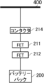
- the switching unit 210 is a schematic diagram showing an example of the configuration of the switching unit 210 including the contactor 214, a discharge FET, and a charge FET.
- the switching unit 210 may have a contactor 214 connected to the bus 400, and a discharge FET and a charge FET connected in series between the contactor 214 and the battery pack 200.
- the management unit 110 keeps the contactor 214 off, for example, while the system 10 is located in an area where lightning occurs. This prevents electricity from flowing through the FETs 211, 212, and the battery pack 200 even if lightning strikes the system 10, and protects the FETs 211, 212, and the battery pack 200.
- the management unit 110 may also turn off the contactor 214 if a malfunction occurs in at least one of the FETs 211 and 212 for some reason. If FET211 and FET212 fall into the fault pattern C, electricity flowing through FET211 and FET212 may cause them to heat up and possibly catch fire, but this can be prevented by turning off contactor 214.
- the contactor 214 is of a type that turns off when a control current is applied, but this is not limited thereto.
- the contactor 214 may be of a type that turns on when a control current is applied.
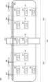
- FIG. 11 shows a schematic diagram of an example of an airplane 600 equipped with the system 10.
- the airplane 600 may be an example of an air vehicle.
- battery packs 220 to 231 are shown as an example of a plurality of battery packs 200.
- battery packs 220 to 224 are arranged in the left wing section 622 of the wing section 620
- battery packs 225 and 226 are arranged in the fuselage 610
- battery packs 227 to 231 are arranged in the right wing section 624 of the wing section 620.
- the management device 100 the multiple switching units 210, the multiple power generation units 300, and the wiring from the battery pack 220 to the bus 400 of the battery pack 231 are not shown.
- the following mainly describes an example in which the multiple switching units 210 are all configured with discharge FETs and charge FETs.
- the management device 100 is disposed, for example, in the fuselage 610 of the airplane 600.
- the power generation unit 300 is disposed, for example, on the upper surface of the wing unit 620.
- the battery packs 220 to 231 are connected in parallel to the bus 400.
- the propeller 630 is an example of a load 500.
- the management unit 110 may repeat the following sequence: select and discharge one battery pack each from the symmetrically arranged groups 901 and 905, select and discharge one battery pack each from the groups 902 and 904, and select and discharge two battery packs from the group 903.
- the order in which one battery pack each is selected from the two symmetrically arranged groups may be selected so that the front-to-back directions match, or may not match.
- the management unit 110 discharges the battery packs 220 and 229, the battery packs 221 and 230, the battery packs 222 and 231 in that order, the battery packs 223 and 227, the battery packs 224 and 228 in that order, and the battery packs 225 and 226.
- the switching units 210 connected to the battery packs 225 and 226 may be configured with contactors 214.
- FIG. 12 shows a schematic diagram of another example of an airplane 600 equipped with the system 10.
- battery packs 220 to 225 are arranged in the left wing section 622 of the wing section 620
- battery packs 226 to 231 are arranged in the right wing section 624 of the wing section 620.
- the management unit 110 may repeat the sequence of selecting and discharging one battery from each of the symmetrically arranged groups 901 and 904, and selecting and discharging one battery from each of the groups 902 and 903.
- the order of selecting one battery from each of the two symmetrically arranged groups may be selected so that the front-to-back directions match, or may not match.
- the management unit 110 discharges battery pack 220 and battery pack 229, battery pack 221 and battery pack 230, battery pack 222 and battery pack 231 in that order, battery pack 223 and battery pack 226, battery pack 224 and battery pack 227, and battery pack 225 and battery pack 228 in that order.
- FIG. 13 shows a schematic diagram of another example of an airplane 600 equipped with the system 10.
- battery packs 220 to 226 are arranged on the left side of the airplane 600
- battery packs 227 to 240 are arranged in the center of the airplane 600
- battery packs 231 to 237 are arranged on the right side of the airplane 600.
- the management unit 110 may repeat the sequence of selecting and discharging one battery from each of the symmetrically arranged groups 901 and 905, selecting and discharging one battery from each of the groups 902 and 904, and selecting and discharging two batteries from the group 903.
- the order of selecting one battery from each of the two symmetrically arranged groups may be selected so that the front-to-back directions match, or may not match.
- the management unit 110 discharges the battery packs 220 and 236, the battery packs 221 and 237 in this order, the battery packs 222 and 231, the battery packs 223 and 232, the battery packs 224 and 233, the battery packs 225 and 234, the battery packs 226 and 235 in this order, and the battery packs 227 and 228, and the battery packs 229 and 230 in this order.
- FIG 14 shows a schematic diagram of another example of an airplane 600 equipped with the system 10.
- battery pack 220, battery pack 223, battery pack 228, and battery pack 229 are arranged in the left wing section 622 of the wing section 620
- battery pack 224 to battery pack 227 are arranged in the center of the airplane 600
- battery pack 230 to battery pack 235 are arranged in the right wing section 624 of the wing section 620.
- the management unit 110 may repeat the sequence of selecting and discharging one battery from each of the symmetrically arranged groups 901 and 905, selecting and discharging one battery from each of the groups 902 and 904, and selecting and discharging two batteries from the group 903.
- the order of selecting one battery from each of the two symmetrically arranged groups may be selected so that the front-to-back directions match, or may not match.
- the management unit 110 discharges the battery packs 220 and 234, the battery packs 221 and 235 in this order, the battery packs 222 and 232, the battery packs 223 and 233 in this order, the battery packs 229 and 231, the battery packs 228 and 230, the battery packs 226 and 227, and the battery packs 224 and 225 in this order.
- FIG. 15 shows a schematic diagram of an example of a HAPS 700 equipped with the system 10.
- the HAPS 700 is an aircraft that provides wireless communication services to user terminals 30 within a communication area 704 formed by irradiating a beam 702 toward the ground.
- HAPS 700 includes an airframe 710, a center section 720, a propeller 730, a pod 740, and solar panels 750.
- Airframe 710 has a wing section 712.
- Wing section 712 includes a left wing section 714 and a right wing section 716.
- a plurality of battery packs 200 connected in parallel are arranged inside the wing 712.
- the plurality of left battery packs 200 may be arranged in the left wing 714, and the plurality of right battery packs 200 may be arranged in the right wing 716.
- the plurality of battery packs 200 may be connected to the bus 400 via a plurality of switching units 210.
- the solar panel 750 may be connected to the bus 400 via the MPPT 320.
- the power discharged by the plurality of battery packs 200 is used by each component of the HAPS 700.
- the power discharged by the plurality of battery packs 200 is used by the motor of the propeller 730.
- the motor of the propeller 730 may be an example of a load 500.
- a flight control section 722 controls the flight of the HAPS 700 using power discharged by the multiple battery packs 200.
- the communication control section 724 controls the communication of the HAPS 700 using power discharged by the multiple battery packs 200.
- the flight control unit 722 controls the flight of the HAPS 700, for example, by controlling the rotation of the propeller 730.
- the flight control unit 722 may also control the flight of the HAPS 700 by changing the angle of flaps or elevators (not shown).
- the flight control unit 722 may be equipped with various sensors, such as a positioning sensor such as a GPS sensor, a gyro sensor, and an acceleration sensor, and may manage the position, movement direction, and movement speed of the HAPS 700.
- the communication control unit 724 uses a service link (SL) antenna to form a communication area 704 on the ground.
- the communication control unit 724 uses the SL antenna to form a service link with a user terminal 30 on the ground.
- the SL antenna may be a multi-beam antenna.
- the communication area 704 may be a multi-cell.
- the communication control unit 724 may use an FL (Feeder Link) antenna to form a feeder link with the ground gateway 40.
- the communication control unit 724 may access the network 20 via the gateway 40.
- the communication control unit 724 may communicate with the communication satellite 50 using a satellite communication antenna.
- the communication control unit 724 may access the network 20 via the communication satellite 50 and the satellite communication station 60.
- the user terminal 30 may be any communication terminal capable of communicating with the HAPS 700.
- the user terminal 30 may be a mobile phone such as a smartphone.
- the user terminal 30 may be a tablet terminal or a PC (Personal Computer), etc.
- the user terminal 30 may be a so-called IoT (Internet of Things) device.
- the user terminal 30 may include anything that falls under the so-called IoE (Internet of Everything).
- HAPS 700 relays communication between the network 20 and the user terminal 30, for example, via a feeder link or a communication satellite 50 and a service link. HAPS 700 may provide wireless communication services to the user terminal 30 by relaying communication between the user terminal 30 and the network 20.
- the network 20 includes a mobile communication network.
- the mobile communication network may conform to any of the following communication methods: 3G (3rd Generation), LTE (Long Term Evolution), 5G (5th Generation), and 6G (6th Generation) or later.
- the network 20 may include the Internet.
- the HAPS 700 transmits data received from a user terminal 30 within the communication area 704 to the network 20. Also, when the HAPS 700 receives data addressed to a user terminal 30 within the communication area 704 via the network 20, it transmits the data to the user terminal 30.
- HAPS700 maintains a communication area 704 in a specific area on the ground, for example, in the stratosphere while circling a predetermined flight path.
- HAPS700 stores electricity generated by solar panels 750 in multiple battery packs 200 during the day, and maintains flight in the stratosphere by using the power of the multiple battery packs 200 at night.
- HAPS700 maintains flight in the stratosphere, for example, by rising and storing potential energy while charging the multiple battery packs 200 during the day, and by descending gently at night and operating the propellers 730 etc. using the power of the battery packs 200 as appropriate.
- the management device 800 manages multiple HAPS 700.
- the management device 800 may communicate with the HAPS 700 via the network 20 and the gateway 40.
- the management device 800 may communicate with the HAPS 700 via the network 20, the satellite communication station 60, and the communication satellite 50.
- the management device 800 controls the HAPS 700 by sending instructions.
- the management device 800 may cause the HAPS 700 to circle above a target area on the ground so that the communication area 704 covers the target area. For example, while flying in a circular orbit above the target area, the HAPS 700 maintains a feeder link with the gateway 40 by adjusting the direction of the FL antenna, and maintains coverage of the target area by the communication area 704 by adjusting the direction of the SL antenna.
- the management unit 110 of the management device 100 manages the multiple battery packs 200 so that the multiple battery packs 200 are alternately discharged so that the voltage difference between the battery pack 200 with the highest voltage and the battery pack 200 with the lowest voltage does not exceed the voltage threshold. This reduces the deterioration of the multiple battery packs 200 as described above, and extends the period during which the HAPS 700 can maintain flight in the stratosphere.
- the management unit 110 may manage the HAPS 700 to rise using the power generated by the solar panel 750 so that the charge rate at which the multiple battery packs 200 are charged by the power generated by the solar panel 750 does not become faster than the charge rate threshold.
- the management unit 110 controls the power generated by the solar panel 750 to be supplied to the propeller 730, flaps, elevator, etc., and the flight control unit 722 controls the propeller 730, flaps, and elevator to raise the HAPS 700.
- the surplus power By converting the surplus power into potential energy, the surplus power can be made available without waste.
- the management unit 110 may manage the load 500 to be increased by the power of the discharging battery pack 200 when the discharge rate of the discharging battery pack 200 among the multiple battery packs 200 continues to be slower than the discharge rate threshold for a predetermined period of time.
- the management unit 110 controls the power of the discharging battery pack 200 to be supplied to the propeller 730, flaps, elevator, etc.
- the flight control unit 722 controls the propeller 730, flaps, and elevator to raise the HAPS 700.
- the management unit 110 may manage the battery packs 200 so that during a time period determined as daytime, the battery packs 200 are alternately discharged so that the voltage difference between the battery pack 200 with the highest voltage and the battery pack 200 with the lowest voltage does not exceed a first voltage threshold, and during a time period determined as nighttime, the battery packs 200 are alternately discharged so that the voltage difference between the battery pack 200 with the highest voltage and the battery pack 200 with the lowest voltage does not exceed a second voltage threshold that is greater than the first voltage threshold.
- the battery packs 200 are not charged by the solar panel 750, so there is little problem even if the voltage difference between the battery pack 200 with the highest voltage and the battery pack 200 with the lowest voltage is greater than during the day.
- FIG. 16 shows a schematic diagram of an example of a hardware configuration of a computer 1200 functioning as the management device 100.
- a program installed on the computer 1200 can cause the computer 1200 to function as one or more "parts" of the device according to the above embodiment, or cause the computer 1200 to execute operations or one or more "parts” associated with the device according to the above embodiment, and/or cause the computer 1200 to execute a process or steps of the process according to the above embodiment.
- Such a program can be executed by the CPU 1212 to cause the computer 1200 to execute specific operations associated with some or all of the blocks of the flowcharts and block diagrams described herein.
- the computer 1200 includes a CPU 1212, a RAM 1214, and a graphics controller 1216, which are interconnected by a host controller 1210.
- the computer 1200 also includes a communication interface 1222, a storage device 1224, and input/output units such as a DVD drive and an IC card drive, which are connected to the host controller 1210 via the input/output controller 1220.
- the storage device 1224 may be a hard disk drive, a solid state drive, or the like.
- the computer 1200 also includes a ROM 1230 and a legacy input/output unit such as a keyboard, which are connected to the input/output controller 1220 via an input/output chip 1240.
- the CPU 1212 operates according to the programs stored in the ROM 1230 and the RAM 1214, thereby controlling each unit.
- the graphics controller 1216 acquires image data generated by the CPU 1212 into a frame buffer or the like provided in the RAM 1214 or into itself, and causes the image data to be displayed on the display device 1218.
- the communication interface 1222 communicates with other electronic devices via a network.
- the storage device 1224 stores programs and data used by the CPU 1212 in the computer 1200.
- the IC card drive reads programs and data from an IC card and/or writes programs and data to an IC card.
- ROM 1230 stores therein a boot program or the like executed by computer 1200 upon activation, and/or a program that depends on the hardware of computer 1200.
- I/O chip 1240 may also connect various I/O units to I/O controller 1220 via USB ports, parallel ports, serial ports, keyboard ports, mouse ports, etc.
- the programs are provided by a computer-readable storage medium such as a DVD-ROM or an IC card.
- the programs are read from the computer-readable storage medium, installed in storage device 1224, RAM 1214, or ROM 1230, which are also examples of computer-readable storage media, and executed by CPU 1212.
- the information processing described in these programs is read by computer 1200, and brings about cooperation between the programs and the various types of hardware resources described above.
- An apparatus or method may be constructed by realizing the operation or processing of information according to the use of computer 1200.
- CPU 1212 may execute a communication program loaded into RAM 1214 and instruct communication interface 1222 to perform communication processing based on the processing described in the communication program.
- communication interface 1222 reads transmission data stored in a transmission buffer area provided in RAM 1214, storage device 1224, a DVD-ROM, or a recording medium such as an IC card, and transmits the read transmission data to the network, or writes received data received from the network to a reception buffer area or the like provided on the recording medium.
- the CPU 1212 may also cause all or a necessary portion of a file or database stored in an external recording medium such as the storage device 1224, a DVD drive (DVD-ROM), an IC card, etc. to be read into the RAM 1214, and perform various types of processing on the data on the RAM 1214. The CPU 1212 may then write back the processed data to the external recording medium.
- an external recording medium such as the storage device 1224, a DVD drive (DVD-ROM), an IC card, etc.
- CPU 1212 may perform various types of processing on data read from RAM 1214, including various types of operations, information processing, conditional judgment, conditional branching, unconditional branching, information search/replacement, etc., as described throughout this disclosure and specified by the instruction sequence of the program, and write back the results to RAM 1214.
- CPU 1212 may also search for information in a file, database, etc. in the recording medium.
- CPU 1212 may search for an entry whose attribute value of the first attribute matches a specified condition from among the multiple entries, read the attribute value of the second attribute stored in the entry, and thereby obtain the attribute value of the second attribute associated with the first attribute that satisfies a predetermined condition.
- the above-described programs or software modules may be stored in a computer-readable storage medium on the computer 1200 or in the vicinity of the computer 1200.
- a recording medium such as a hard disk or RAM provided in a server system connected to a dedicated communication network or the Internet can be used as a computer-readable storage medium, thereby providing the programs to the computer 1200 via the network.
- the blocks in the flowcharts and block diagrams in this embodiment may represent stages of a process where an operation is performed or "parts" of a device responsible for performing the operation. Particular stages and “parts" may be implemented by dedicated circuitry, programmable circuitry provided with computer-readable instructions stored on a computer-readable storage medium, and/or a processor provided with computer-readable instructions stored on a computer-readable storage medium.
- the dedicated circuitry may include digital and/or analog hardware circuitry and may include integrated circuits (ICs) and/or discrete circuits.
- the programmable circuitry may include reconfigurable hardware circuitry including AND, OR, XOR, NAND, NOR, and other logical operations, flip-flops, registers, and memory elements, such as, for example, field programmable gate arrays (FPGAs) and programmable logic arrays (PLAs).
- FPGAs field programmable gate arrays
- PDAs programmable logic arrays
- a computer-readable storage medium may include any tangible device capable of storing instructions that are executed by a suitable device, such that a computer-readable storage medium having instructions stored thereon comprises an article of manufacture that includes instructions that can be executed to create means for performing the operations specified in the flowchart or block diagram.
- Examples of computer-readable storage media may include electronic storage media, magnetic storage media, optical storage media, electromagnetic storage media, semiconductor storage media, and the like.
- Computer-readable storage media may include floppy disks, diskettes, hard disks, random access memories (RAMs), read-only memories (ROMs), erasable programmable read-only memories (EPROMs or flash memories), electrically erasable programmable read-only memories (EEPROMs), static random access memories (SRAMs), compact disk read-only memories (CD-ROMs), digital versatile disks (DVDs), Blu-ray disks, memory sticks, integrated circuit cards, and the like.
- RAMs random access memories
- ROMs read-only memories
- EPROMs or flash memories erasable programmable read-only memories
- EEPROMs electrically erasable programmable read-only memories
- SRAMs static random access memories
- CD-ROMs compact disk read-only memories
- DVDs digital versatile disks
- Blu-ray disks memory sticks, integrated circuit cards, and the like.
- the computer readable instructions may include either assembler instructions, instruction set architecture (ISA) instructions, machine instructions, machine-dependent instructions, microcode, firmware instructions, state setting data, or source or object code written in any combination of one or more programming languages, including object-oriented programming languages such as Smalltalk (registered trademark), JAVA (registered trademark), C++, etc., and conventional procedural programming languages such as the "C" programming language or similar programming languages.
- ISA instruction set architecture
- machine instructions machine-dependent instructions
- microcode firmware instructions
- state setting data or source or object code written in any combination of one or more programming languages, including object-oriented programming languages such as Smalltalk (registered trademark), JAVA (registered trademark), C++, etc., and conventional procedural programming languages such as the "C" programming language or similar programming languages.
- the computer-readable instructions may be provided to a processor of a general-purpose computer, special-purpose computer, or other programmable data processing apparatus, or to a programmable circuit, either locally or over a local area network (LAN), a wide area network (WAN) such as the Internet, so that the processor of the general-purpose computer, special-purpose computer, or other programmable data processing apparatus, or to a programmable circuit, executes the computer-readable instructions to generate means for performing the operations specified in the flowcharts or block diagrams.
- processors include computer processors, processing units, microprocessors, digital signal processors, controllers, microcontrollers, etc.
- 10 system 20 network, 30 user terminal, 40 gateway, 50 communication satellite, 60 satellite communication station, 100 management device, 110 management unit, 112 pack-related information acquisition unit, 114 estimation unit, 116 receiving unit, 200 battery pack, 202 cell, 210 switching unit, 211 FET, 212 FET, 214 contactor, 220, 221, 222, 223, 224, 225, 226, 227, 228, 229, 230, 231, 232, 233, 234, 235, 236, 237 battery pack, 300 power generation unit, 310 solar cell, 320 MPPT, 400 bus, 500 load, 510 controller, 600 airplane, 610 fuselage, 620 wing , 622 left wing, 624 right wing, 630 propeller, 700 HAPS, 702 beam, 704 communication area, 710 fuselage, 712 wing, 714 left wing, 716 right wing, 720 center, 722 flight control unit, 724 communication control unit, 730 propeller, 740 pod, 750 solar panel, 800 management device, 901, 902,
Landscapes
- Engineering & Computer Science (AREA)
- Power Engineering (AREA)
- Aviation & Aerospace Engineering (AREA)
- Charge And Discharge Circuits For Batteries Or The Like (AREA)
- Secondary Cells (AREA)
Abstract
Description
[先行技術文献]
[特許文献]
[特許文献1]特開2020-043494号公報

Claims (19)
- 発電部及び負荷が接続されたバスに対して並列に接続された複数の切替部であって、それぞれが前記バスに対するバッテリーパックの接続のオンオフを切り替える複数の切替部と、
前記複数の切替部のそれぞれに接続された複数の前記バッテリーパックと、
前記複数のバッテリーパックのすべてが放電する場合と比較して、前記複数のバッテリーパックのそれぞれの放電レートが高くなるように、前記複数のバッテリーパックに交互に放電させるように前記複数の切替部を管理する管理部と
を備え、
前記複数の切替部のうちの少なくともいずれかは、接続された前記バッテリーパックから前記バスに対して電流が流れる放電状態、前記バスから前記バッテリーパックに対して電流が流れる充電状態、及び前記バスと前記バッテリーパックとの間に電流が流れない切断状態とを切替可能な、放電用FET及び充電用FETを有する、システム。 - 前記複数の切替部のうちの一部は、前記放電用FET及び前記充電用FETを有し、前記複数の切替部のうちの他の一部は、前記バスに接続されたコンタクタと、前記コンタクタと前記バッテリーパックとの間に直列に接続された前記放電用FET及び前記充電用FETとを有する、請求項1に記載のシステム。
- 前記管理部は、予め定められた条件が満たされている間、前記複数の切替部のうちの前記他の一部の前記コンタクタをオフの状態で維持する、請求項2に記載のシステム。
- 前記管理部は、前記システムが、雷が発生するエリアに位置する間、前記複数の切替部のうちの前記他の一部の前記コンタクタをオフの状態で維持する、請求項3に記載のシステム。
- 前記管理部は、前記複数の切替部のうちの前記他の一部の前記放電用FET及び前記充電用FETの少なくともいずれかに不具合が発生している場合、当該他の一部の前記コンタクタをオフの状態で維持する、請求項3又は4に記載のシステム。
- 前記コンタクタは、制御電流が加わったときにオフになるタイプであり、
前記管理部は、前記予め定められた条件が満たされている間、前記コンタクタに対して前記制御電流を加える、請求項3から5のいずれか一項に記載のシステム。 - 前記複数の切替部のうちの一部は、前記放電用FET及び前記充電用FETを有し、前記複数の切替部のうちの他の一部は、接続された前記バッテリーパックと前記バスとの間の電流のオンオフを切り替えるコンタクタを有する、請求項1に記載のシステム。
- 前記管理部は、充電時において、前記複数の切替部のうちの前記一部を前記充電状態にし、前記複数の切替部のうちの前記他の一部の前記コンタクタをオンにし、放電時において、前記複数の切替部のうちの前記他の一部の前記コンタクタをオンにし、前記複数の切替部のうちの前記一部を交互に前記放電状態にする、請求項7に記載のシステム。
- 前記管理部は、前記放電時において、前記複数の切替部のうちの前記一部について、同時に全ての前記切替部が前記放電状態にならないように交互に前記放電状態にする、請求項8に記載のシステム。
- 前記複数の切替部のすべてが、前記放電用FET及び前記充電用FETを有する、請求項1に記載のシステム。
- 前記複数の切替部のすべてが、前記バスに接続されたコンタクタと、前記コンタクタと前記バッテリーパックとの間に直列に接続された前記放電用FET及び前記充電用FETとを有する、請求項1に記載のシステム。
- 前記管理部は、予め定められた条件が満たされている間、前記複数の切替部のうちの一部の切替部の前記コンタクタをオフの状態で維持する、請求項11に記載のシステム。
- 前記管理部は、前記システムが、雷が発生するエリアに位置する間、前記複数の切替部のうちの前記一部の切替部の前記コンタクタのみをオンとし、前記複数の切替部のうちの他の切替部の前記コンタクタをオフの状態で維持する、請求項12に記載のシステム。
- 前記複数の切替部の前記コンタクタは、制御電流が加わったときにオフになるタイプであり、
前記管理部は、前記システムが、雷が発生するエリアに位置する間、前記複数の切替部のうちの前記他の切替部の前記コンタクタに対して前記制御電流を加える、請求項13に記載のシステム。 - 前記管理部は、前記複数のバッテリーパックのうち、電圧が最大のバッテリーパックと、電圧が最小のバッテリーパックとの電圧の差が電圧閾値より大きくならないように、前記複数のバッテリーパックに交互に放電させるように前記複数の切替部を制御する、請求項1から14のいずれか一項に記載のシステム。
- 前記管理部は、前記発電部によって発電された電力によって、前記複数のバッテリーパックを同時に充電するように、前記複数の切替部を制御する、請求項1から15のいずれか一項に記載のシステム。
- 前記システムは飛行体に搭載され、
前記複数のバッテリーパックは前記飛行体の翼部に配置され、
前記発電部は太陽光発電を実行し、
前記負荷は、前記飛行体のプロペラを回転させるモータである、請求項1から16のいずれか一項に記載のシステム。 - 前記飛行体を備える、請求項17に記載のシステム。
- 前記飛行体は、
前記複数のバッテリーパックによって放電された電力を用いて、地上に向けてビームを照射することにより形成した通信エリア内のユーザ端末に無線通信サービスを提供する通信制御部
を有する、請求項18に記載のシステム。
Priority Applications (3)
| Application Number | Priority Date | Filing Date | Title |
|---|---|---|---|
| EP23877014.3A EP4557571A4 (en) | 2022-10-13 | 2023-08-24 | SYSTEM |
| CN202380059976.3A CN119731907A (zh) | 2022-10-13 | 2023-08-24 | 系统 |
| US18/970,932 US12374904B2 (en) | 2022-10-13 | 2024-12-06 | Control system for alternately discharging battery packs of a power system |
Applications Claiming Priority (2)
| Application Number | Priority Date | Filing Date | Title |
|---|---|---|---|
| JP2022164496A JP7500680B2 (ja) | 2022-10-13 | 2022-10-13 | システム |
| JP2022-164496 | 2022-10-13 |
Related Child Applications (1)
| Application Number | Title | Priority Date | Filing Date |
|---|---|---|---|
| US18/970,932 Continuation US12374904B2 (en) | 2022-10-13 | 2024-12-06 | Control system for alternately discharging battery packs of a power system |
Publications (1)
| Publication Number | Publication Date |
|---|---|
| WO2024080006A1 true WO2024080006A1 (ja) | 2024-04-18 |
Family
ID=90669401
Family Applications (1)
| Application Number | Title | Priority Date | Filing Date |
|---|---|---|---|
| PCT/JP2023/030617 Ceased WO2024080006A1 (ja) | 2022-10-13 | 2023-08-24 | システム |
Country Status (5)
| Country | Link |
|---|---|
| US (1) | US12374904B2 (ja) |
| EP (1) | EP4557571A4 (ja) |
| JP (1) | JP7500680B2 (ja) |
| CN (1) | CN119731907A (ja) |
| WO (1) | WO2024080006A1 (ja) |
Families Citing this family (4)
| Publication number | Priority date | Publication date | Assignee | Title |
|---|---|---|---|---|
| JP2024143917A (ja) * | 2023-03-31 | 2024-10-11 | 本田技研工業株式会社 | 電力供給システム、電力供給システムを備える移動体、及び、電力供給システムの制御方法 |
| JP2024143933A (ja) * | 2023-03-31 | 2024-10-11 | 本田技研工業株式会社 | 電力供給システム及び電力供給システムを備える移動体 |
| JP2024143912A (ja) * | 2023-03-31 | 2024-10-11 | 本田技研工業株式会社 | 電力供給システム、電力供給システムを備える移動体、及び、電力供給システムの制御方法 |
| JP7761111B1 (ja) * | 2024-10-09 | 2025-10-28 | 富士電機株式会社 | 制御システム |
Citations (6)
| Publication number | Priority date | Publication date | Assignee | Title |
|---|---|---|---|---|
| JPH09312172A (ja) * | 1996-05-22 | 1997-12-02 | Sony Corp | バッテリパック、充電器、および充電システム、並びに充電方法 |
| JP2008125199A (ja) * | 2006-11-09 | 2008-05-29 | Sanyo Electric Co Ltd | パック電池の制御方法 |
| JP2013153545A (ja) * | 2010-08-06 | 2013-08-08 | Sanyo Electric Co Ltd | 電池並列処理回路及び電池システム |
| WO2016121072A1 (ja) * | 2015-01-29 | 2016-08-04 | 株式会社自律制御システム研究所 | 飛行ロボット装置 |
| JP2020043494A (ja) | 2018-09-11 | 2020-03-19 | Hapsモバイル株式会社 | 制御装置、プログラム、制御方法及び飛行体 |
| JP2021166436A (ja) * | 2020-04-07 | 2021-10-14 | ソフトバンク株式会社 | システム、プログラム、管理方法、及び飛行体 |
Family Cites Families (14)
| Publication number | Priority date | Publication date | Assignee | Title |
|---|---|---|---|---|
| DE102009019531A1 (de) * | 2009-04-30 | 2009-12-24 | Daimler Ag | Elektrisch antreibbares Kraftfahrzeug |
| US8946937B2 (en) * | 2010-08-18 | 2015-02-03 | Volterra Semiconductor Corporation | Switching circuits for extracting power from an electric power source and associated methods |
| JP5867345B2 (ja) * | 2012-09-03 | 2016-02-24 | カシオ計算機株式会社 | 充電装置および充電方法 |
| JP5772781B2 (ja) * | 2012-10-10 | 2015-09-02 | トヨタ自動車株式会社 | 車両、電源システムおよび電源システムの制御方法 |
| JP6293010B2 (ja) * | 2014-07-23 | 2018-03-14 | 本田技研工業株式会社 | 蓄電システム |
| US10076964B2 (en) * | 2015-12-15 | 2018-09-18 | Faraday & Future Inc. | Pre-charge system and method |
| TWI624133B (zh) * | 2016-11-08 | 2018-05-11 | 磐石電池股份有限公司 | Charge and discharge balance control device and method |
| JP6723204B2 (ja) * | 2017-08-07 | 2020-07-15 | 三菱重工業株式会社 | 充放電制御装置、充放電制御システム、充放電制御方法及び充放電制御プログラム |
| US10367358B2 (en) * | 2018-01-03 | 2019-07-30 | Fu-Chieh Chen | Active equalizing charging device |
| CN110797925B (zh) * | 2018-08-01 | 2021-08-03 | Oppo广东移动通信有限公司 | 电池控制系统和方法、电子设备 |
| JP7144466B2 (ja) * | 2020-01-28 | 2022-09-29 | 矢崎総業株式会社 | 電池制御ユニットおよび電池システム |
| US20220029431A1 (en) * | 2020-07-23 | 2022-01-27 | Aurora Flight Sciences Corporation, a subsidiary of The Boeing Company | Switchable Battery Management System |
| EP4233084B1 (de) * | 2020-12-21 | 2026-02-11 | Siemens Aktiengesellschaft | Schutzschaltgerät und verfahren |
| KR102844151B1 (ko) * | 2021-01-11 | 2025-08-07 | 주식회사 엘지에너지솔루션 | 배터리 제어 장치, 배터리 시스템, 전원 공급 시스템 및 배터리 제어 방법 |
-
2022
- 2022-10-13 JP JP2022164496A patent/JP7500680B2/ja active Active
-
2023
- 2023-08-24 EP EP23877014.3A patent/EP4557571A4/en active Pending
- 2023-08-24 CN CN202380059976.3A patent/CN119731907A/zh active Pending
- 2023-08-24 WO PCT/JP2023/030617 patent/WO2024080006A1/ja not_active Ceased
-
2024
- 2024-12-06 US US18/970,932 patent/US12374904B2/en active Active
Patent Citations (6)
| Publication number | Priority date | Publication date | Assignee | Title |
|---|---|---|---|---|
| JPH09312172A (ja) * | 1996-05-22 | 1997-12-02 | Sony Corp | バッテリパック、充電器、および充電システム、並びに充電方法 |
| JP2008125199A (ja) * | 2006-11-09 | 2008-05-29 | Sanyo Electric Co Ltd | パック電池の制御方法 |
| JP2013153545A (ja) * | 2010-08-06 | 2013-08-08 | Sanyo Electric Co Ltd | 電池並列処理回路及び電池システム |
| WO2016121072A1 (ja) * | 2015-01-29 | 2016-08-04 | 株式会社自律制御システム研究所 | 飛行ロボット装置 |
| JP2020043494A (ja) | 2018-09-11 | 2020-03-19 | Hapsモバイル株式会社 | 制御装置、プログラム、制御方法及び飛行体 |
| JP2021166436A (ja) * | 2020-04-07 | 2021-10-14 | ソフトバンク株式会社 | システム、プログラム、管理方法、及び飛行体 |
Non-Patent Citations (1)
| Title |
|---|
| See also references of EP4557571A4 |
Also Published As
| Publication number | Publication date |
|---|---|
| US12374904B2 (en) | 2025-07-29 |
| JP7500680B2 (ja) | 2024-06-17 |
| EP4557571A4 (en) | 2025-12-17 |
| CN119731907A (zh) | 2025-03-28 |
| JP2024057688A (ja) | 2024-04-25 |
| US20250096580A1 (en) | 2025-03-20 |
| EP4557571A1 (en) | 2025-05-21 |
Similar Documents
| Publication | Publication Date | Title |
|---|---|---|
| JP7500680B2 (ja) | システム | |
| JP7549083B2 (ja) | システム、プログラム、及び管理方法 | |
| US20230044238A1 (en) | System, program, management method, and aircraft | |
| US11813946B2 (en) | Fail operational vehicle power supply | |
| CN115367123B (zh) | 飞行器的动力分配网络中的电故障隔离 | |
| US20210020998A1 (en) | Power pack and power pack circuitry | |
| US11187751B2 (en) | Relay operation state maintaining device and electronic device including the same | |
| US11962147B2 (en) | Circuit and system for coupling battery packs to motor controller in electric or hybrid aircraft | |
| KR20220095354A (ko) | 항공모빌리티의 전력 관리 시스템 및 그 운영방법 | |
| JP7756882B2 (ja) | システム | |
| CN114636940B (zh) | 故障检测方法、电池管理系统及整机控制器 | |
| CN107681762A (zh) | 一种平流层浮空器供电结构 | |
| JP7121773B2 (ja) | 制御装置、システム、プログラム及び制御方法 | |
| JP7583619B2 (ja) | 制御装置、プログラム、システム及び制御方法 | |
| JP7463484B1 (ja) | 発電システム、及び飛行体 | |
| JP7076488B2 (ja) | 管理装置、プログラム、システム及び制御方法 | |
| RU2730703C1 (ru) | Способ эксплуатации многоблочной литий-ионной аккумуляторной батареи в составе космического аппарата | |
| CN117118008A (zh) | 卫星用锂离子蓄电池组过放电保护方法及系统 | |
| JP2024129432A (ja) | 制御装置、プログラム、及び飛行体 |
Legal Events
| Date | Code | Title | Description |
|---|---|---|---|
| 121 | Ep: the epo has been informed by wipo that ep was designated in this application |
Ref document number: 23877014 Country of ref document: EP Kind code of ref document: A1 |
|
| WWE | Wipo information: entry into national phase |
Ref document number: 2023877014 Country of ref document: EP |
|
| WWE | Wipo information: entry into national phase |
Ref document number: 202380059976.3 Country of ref document: CN |
|
| ENP | Entry into the national phase |
Ref document number: 2023877014 Country of ref document: EP Effective date: 20250213 |
|
| WWP | Wipo information: published in national office |
Ref document number: 202380059976.3 Country of ref document: CN |
|
| NENP | Non-entry into the national phase |
Ref country code: DE |
|
| WWP | Wipo information: published in national office |
Ref document number: 2023877014 Country of ref document: EP |