WO2024084892A1 - 給電システム、電動工具システム、及び給電装置 - Google Patents
給電システム、電動工具システム、及び給電装置 Download PDFInfo
- Publication number
- WO2024084892A1 WO2024084892A1 PCT/JP2023/034441 JP2023034441W WO2024084892A1 WO 2024084892 A1 WO2024084892 A1 WO 2024084892A1 JP 2023034441 W JP2023034441 W JP 2023034441W WO 2024084892 A1 WO2024084892 A1 WO 2024084892A1
- Authority
- WO
- WIPO (PCT)
- Prior art keywords
- power
- storage battery
- tool
- battery
- power supply
- Prior art date
- Legal status (The legal status is an assumption and is not a legal conclusion. Google has not performed a legal analysis and makes no representation as to the accuracy of the status listed.)
- Ceased
Links
Images



Classifications
-
- H—ELECTRICITY
- H02—GENERATION; CONVERSION OR DISTRIBUTION OF ELECTRIC POWER
- H02J—ELECTRIC POWER NETWORKS; CIRCUIT ARRANGEMENTS OR SYSTEMS FOR SUPPLYING OR DISTRIBUTING ELECTRIC POWER; SYSTEMS FOR STORING ELECTRIC ENERGY
- H02J7/00—Circuit arrangements for charging or discharging batteries or for supplying loads from batteries
- H02J7/80—Circuit arrangements for charging or discharging batteries or for supplying loads from batteries including monitoring or indicating arrangements
-
- B—PERFORMING OPERATIONS; TRANSPORTING
- B25—HAND TOOLS; PORTABLE POWER-DRIVEN TOOLS; MANIPULATORS
- B25F—COMBINATION OR MULTI-PURPOSE TOOLS NOT OTHERWISE PROVIDED FOR; DETAILS OR COMPONENTS OF PORTABLE POWER-DRIVEN TOOLS NOT PARTICULARLY RELATED TO THE OPERATIONS PERFORMED AND NOT OTHERWISE PROVIDED FOR
- B25F5/00—Details or components of portable power-driven tools not particularly related to the operations performed and not otherwise provided for
-
- H—ELECTRICITY
- H02—GENERATION; CONVERSION OR DISTRIBUTION OF ELECTRIC POWER
- H02J—ELECTRIC POWER NETWORKS; CIRCUIT ARRANGEMENTS OR SYSTEMS FOR SUPPLYING OR DISTRIBUTING ELECTRIC POWER; SYSTEMS FOR STORING ELECTRIC ENERGY
- H02J7/00—Circuit arrangements for charging or discharging batteries or for supplying loads from batteries
- H02J7/34—Parallel operation in networks using both storage and other DC sources, e.g. providing buffering
- H02J7/342—The other DC source being a battery actively interacting with the first one, i.e. battery to battery charging
-
- H—ELECTRICITY
- H02—GENERATION; CONVERSION OR DISTRIBUTION OF ELECTRIC POWER
- H02J—ELECTRIC POWER NETWORKS; CIRCUIT ARRANGEMENTS OR SYSTEMS FOR SUPPLYING OR DISTRIBUTING ELECTRIC POWER; SYSTEMS FOR STORING ELECTRIC ENERGY
- H02J7/00—Circuit arrangements for charging or discharging batteries or for supplying loads from batteries
- H02J7/70—Circuit arrangements for charging or discharging batteries or for supplying loads from batteries characterised by the mechanical construction
- H02J7/731—Circuit arrangements for charging or discharging batteries or for supplying loads from batteries characterised by the mechanical construction specially adapted for holding portable devices containing batteries
-
- H—ELECTRICITY
- H02—GENERATION; CONVERSION OR DISTRIBUTION OF ELECTRIC POWER
- H02J—ELECTRIC POWER NETWORKS; CIRCUIT ARRANGEMENTS OR SYSTEMS FOR SUPPLYING OR DISTRIBUTING ELECTRIC POWER; SYSTEMS FOR STORING ELECTRIC ENERGY
- H02J7/00—Circuit arrangements for charging or discharging batteries or for supplying loads from batteries
- H02J7/70—Circuit arrangements for charging or discharging batteries or for supplying loads from batteries characterised by the mechanical construction
-
- Y—GENERAL TAGGING OF NEW TECHNOLOGICAL DEVELOPMENTS; GENERAL TAGGING OF CROSS-SECTIONAL TECHNOLOGIES SPANNING OVER SEVERAL SECTIONS OF THE IPC; TECHNICAL SUBJECTS COVERED BY FORMER USPC CROSS-REFERENCE ART COLLECTIONS [XRACs] AND DIGESTS
- Y02—TECHNOLOGIES OR APPLICATIONS FOR MITIGATION OR ADAPTATION AGAINST CLIMATE CHANGE
- Y02E—REDUCTION OF GREENHOUSE GAS [GHG] EMISSIONS, RELATED TO ENERGY GENERATION, TRANSMISSION OR DISTRIBUTION
- Y02E60/00—Enabling technologies; Technologies with a potential or indirect contribution to GHG emissions mitigation
- Y02E60/10—Energy storage using batteries
Definitions
- the present disclosure relates to a power supply system, a power tool system, and a power supply device, and more specifically to a power supply system, a power tool system, and a power supply device that supply power to a handheld power tool.
- Patent Document 1 describes a power supply adapter device for power tools that supplies power from a portable, large-capacity storage battery to the power tool using a power relay unit that is similar in shape to a conventionally used rechargeable battery.
- the objective of this disclosure is to provide a power supply system, a power tool system, and a power supply device that can improve workability.
- the power supply system supplies power to a handheld power tool.
- the power supply system includes a first storage battery, a power supply circuit, a second storage battery, and a tool holding unit.
- the power supply circuit converts AC power from a commercial power source into DC power and supplies it to the first storage battery.
- the second storage battery is built into the power tool, or built into a battery pack that can be attached to the power tool.
- the tool holding unit can hold a battery-equipped power tool, and while holding the battery-equipped power tool, supplies power from the first storage battery to the second storage battery.
- the battery-equipped power tool is the power tool with the second storage battery built in, or the power tool to which the battery pack with the second storage battery built in is attached.
- the power tool system includes the power supply system and a battery-equipped power tool.
- the battery-equipped power tool is the power tool with the second storage battery built in, or the power tool to which the battery pack with the second storage battery built in is attached.
- the power supply device supplies power to a handheld power tool.
- the power supply device includes a first storage battery, a power supply circuit, and a tool holding unit.
- the power supply circuit converts AC power from a commercial power source into DC power and supplies it to the first storage battery.
- the tool holding unit is capable of holding a battery-equipped power tool, and while holding the battery-equipped power tool, supplies power from the first storage battery to a second storage battery.
- the battery-equipped power tool is the power tool with the second storage battery built in, or the power tool with a battery pack with the second storage battery built in attached.
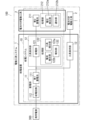
- FIG. 1 is a block diagram of a power tool system including a power supply system according to an embodiment of the present disclosure.
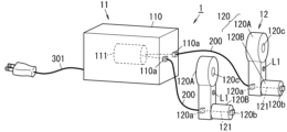
- FIG. 2 is a schematic view of a power supply device constituting the power supply system.
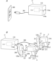
- FIG. 3A is a diagram for explaining the procedure for supplying power to a first storage battery that constitutes the above-mentioned power supply system
- FIG. 3B is a diagram for explaining the procedure for supplying power to a second storage battery that constitutes the above-mentioned power supply system.
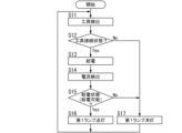
- FIG. 4 is a flowchart illustrating a first notification process by a tool holding unit constituting the power supply system.
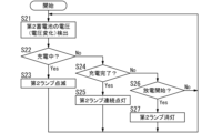
- FIG. 5 is a flowchart illustrating a second notification process performed by a battery-powered power tool constituting the power supply system.
- FIG. 1 is a block diagram of a power tool system including a power supply system according to an embodiment of the present disclosure.
- FIG. 2 is a schematic view of a power supply device constituting the power supply system.
- FIG. 3A is
- FIG. 6 is a block diagram showing a modification of the above power supply system.
- FIG. 7A is a schematic diagram of a power supply device constituting the above modified example
- FIG. 7B is a diagram for explaining a procedure for supplying power to a second storage battery constituting the above modified example.
- FIG. 8 is a flowchart illustrating a notification process performed by the tool holding unit constituting the modified example of the above embodiment.
- FIG. 9 is a flowchart illustrating a second lamp lighting control process constituting the notification process of the above embodiment.
- FIG. 10 is a flowchart illustrating an instruction process performed by a battery-powered power tool according to the above modified example.
- a power supply system 10 (hereinafter, referred to as "power supply system 10 of the present disclosure") according to an embodiment (see FIGS. 1 to 5) or modified examples (see FIGS. 6 to 10) of the present disclosure is a power tool power supply system that supplies power to a power tool 21.
- the power tool 21 in the present disclosure is a handheld tool that operates on DC power obtained by converting AC power.
- the power tool 21 is, for example, a rotating tool such as an electric screwdriver, but may also be a cutting tool, and the type of the power tool is not important.
- the power supply system 10 includes a first storage battery 111, a power supply circuit 112, a second storage battery 211, and a tool holding unit 12.
- the first storage battery 111 stores DC power (hereinafter simply referred to as “power”) obtained by the power supply circuit 112 converting AC power.
- the power supply circuit 112 converts AC power from the commercial power source 300 into DC power and supplies (feeds) the DC power to the first storage battery 111 .
- the second storage battery 211 stores the power supplied from the first storage battery 111 via the tool holding unit 12.
- the second storage battery 211 is built into the battery pack 22 that can be attached to the power tool 21, but may be built into the power tool 21, for example, as described in a modified example.
- the tool holding unit 12 is capable of holding a battery-powered power tool 2 and is a tool holding unit with a power supply function that supplies power from the first storage battery 111 to the second storage battery 211 while holding the battery-powered power tool 2 .
- the battery-powered power tool 2 is a power tool 21 equipped with a battery pack 22 having a built-in second storage battery 211 as shown in FIG. 1, but it may also be a power tool 21 having a built-in second storage battery 211 as described in the modified example shown in FIG. 6.
- the power supply circuit 112 pre-charges the first storage battery 111, and the tool holding unit 12 holds a battery-equipped power tool 2 that includes the second storage battery 211 or has a battery pack 22 that includes the second storage battery 211 attached thereto, while supplying power from the first storage battery 111 to the second storage battery 211.
- the power supply system 10 of the present disclosure includes multiple tool holding units 12. This allows multiple battery-equipped power tools 2 to be charged simultaneously, thereby improving workability.
- the power supply system 10 of the present disclosure includes a power storage unit 11.
- the power storage unit 11 includes a first storage battery 111, a power supply circuit 112, and a first housing 110 as shown in Fig. 2 or 7A.
- the first housing 110 houses the first storage battery 111 and the power supply circuit 112. Note that the power supply circuit 112 is omitted in Figures 2 and 7A and so on.
- the tool holding unit 12 includes a second housing 120 as shown in FIG. 2 or FIG. 7A.
- the second housing 120 houses a power supply unit 121 and a processing unit 122 (both described below), and is capable of holding a battery-equipped power tool 2.
- At least one of the first housing 110 (power storage unit 11) and the multiple second housings 120 (multiple tool holding units 12) is portable.
- the power storage unit 11 and all of the multiple tool holding units 12 may be portable (portable), or only the multiple tool holding units 12 may be portable and the power storage unit 11 may be difficult to carry (fixed).
- the power storage unit 11 and the tool holding unit 12 are separate, and at least one of them is portable, which improves workability in a variety of environments (such as various manufacturing lines that manufacture various products on an assembly line).
- the power supply device 1 constituting the power supply system 10 further includes a power supply terminal 110a, an input terminal 120a, an output terminal 120b, and a power receiving terminal 201, as shown in FIG. 2 or FIG. 7A.
- the power supply terminal 110a is provided on the first housing 110 constituting the power storage unit 11, and is electrically connected to the first storage battery 111 housed in the first housing 110.
- the input terminal 120a is provided on the second housing 120 that constitutes the tool holding unit 12, and can be electrically connected to the power supply terminal 110a via the connection cable 200.
- the output terminal 120b is provided on the second housing 120 and is electrically connected to the input terminal 120a.
- the power receiving terminal 201 is provided on the power tool 21 or the battery pack 22 and is electrically connected to the second storage battery 211 built into the power tool 21 or the battery pack 22.
- the output terminal 120b and the power receiving terminal 201 can be electrically connected by a physical connection.
- a physical connection is when the output terminal 120b and the power receiving terminal 201 come into contact with each other.
- the output terminal 120b is a convex portion provided on the second housing 120 and the power receiving terminal 201 is a convex portion provided on the battery pack 22, the tips of the two convex portions come into contact with each other.
- the output terminal 120b is a convex portion provided on the second housing 120 and the power receiving terminal 201 is a concave portion provided on the battery pack 22, the convex portion may be inserted into the concave portion.
- connection between the power storage unit 11 and the tool holding unit 12 is made via the connection cable 200, which increases the freedom of positioning of the tool holding unit 12 relative to the power storage unit 11.
- connection between the tool holding unit 12 and the battery-equipped power tool 2 is made by a physical connection, and while the physical connection is released, the battery-equipped power tool 2 operates using power from the second storage battery 211, making it possible to move the battery-equipped power tool 2 to any position. As a result, workability can be further improved.
- the tool holding unit 12 includes a power supply unit 121 as shown in FIGS. 1 and 2 or 6 and 7A.
- the power supply unit 121 supplies power when the output terminal 120b and the power receiving terminal 201 are physically connected. Power supply here refers to the supply of power from the first storage battery 111 to the second storage battery 211.
- the battery-equipped power tool 2 is held by an operator's hand with the output terminal 120b and the power receiving terminal 201 physically separated, and performs an operation based on power from the second storage battery 211.
- the operation is to rotate the tool tip 23 attached to the tool body 21A.
- the worker can simply set the battery-equipped power tool 2 on the tool holder 12 between tasks, and the second storage battery 211 will be charged with power from the first storage battery 111. This allows a series of tasks to be performed without changing batteries or removing and attaching the battery pack 22, improving workability.
- the tool holding unit 12 further includes a notification unit (a first notification unit 12A and a second notification unit 12B in the embodiment, and a notification unit 12C in the modified example; hereinafter, these units will be referred to as “notification units (12A, 12B, 12C)”).
- a notification unit a first notification unit 12A and a second notification unit 12B in the embodiment, and a notification unit 12C in the modified example; hereinafter, these units will be referred to as “notification units (12A, 12B, 12C)”.
- the notification unit (12A, 12B, 12C) notifies at least one of whether or not the power supply unit 121 is supplying power and the charging state of the second storage battery 211 based on the power supply (e.g., charging, charging complete, etc.).
- the notification may be, for example, the lighting of the first lamp L1 (notification that power can be supplied) in response to the first storage battery 111 changing from a state in which power cannot be supplied (a state in which a tool is not connected or a state in which no power is being supplied) to a state in which power can be supplied (a state in which a tool is connected and power is being supplied).
- the notification may be a change in the lighting state of the second lamp based on the voltage or voltage change of the second storage battery 211 (for example, flashing to indicate that charging is in progress, continuous lighting to indicate that charging is complete, etc.).
- the first storage battery 111 has a larger capacity than the second storage battery 211.
- the first storage battery 111 has a large capacity, once the first storage battery 111 is charged, it is possible to at least one of simultaneously charge multiple second storage batteries 211 from the first storage battery 111 and repeatedly charge one second storage battery 211 from the first storage battery 111, thereby further improving workability.
- the second storage battery 211 has a faster charging speed than the first storage battery 111. Note that in this embodiment, the second storage battery 211 is a different type of storage battery from the first storage battery 111, and can be charged faster than the first storage battery 111. Therefore, the second storage battery 211 can be charged in a shorter time than the first storage battery 111.
- the second storage battery 211 can be charged at high speed, a series of tasks can be carried out while charging the second storage battery 211 between tasks, thereby further improving workability.
- the second storage battery 211 has a longer life than the first storage battery 111.
- the long life of the second storage battery 211 reduces the frequency of replacement of the second storage battery 211, making it possible to provide a power tool 21 that includes a built-in second storage battery 211 (and therefore does not require a battery pack 22), as described in the modified example shown in FIG. 6.
- the second storage battery 211 has a higher energy density than the first storage battery 111.
- the high energy density of the second storage battery 211 makes it possible to reduce at least one of the volume and weight of the second storage battery 211, thereby making the battery-equipped power tool 2 at least one of smaller and lighter, and thus further improving workability.
- the second storage battery 211 in the present disclosure is an all-solid-state battery.
- the second storage battery 211 may be, for example, a stack of a plurality of thin-plate-shaped all-solid-state batteries.
- the second storage battery 211 being a solid-state battery capable of rapid charging further improves operability.
- the long life of the solid-state battery makes it possible to provide a power tool 21 incorporating the second storage battery 211, which is an all-solid-state battery.
- the high energy density of the solid-state battery makes it possible to at least one of reduce the size and weight of the battery-equipped power tool 2, thereby further improving operability.
- a power tool system 100 includes the power supply system 10 as described above and a battery-equipped power tool 2, as shown in FIG. 1 or FIG. 6.
- the battery-equipped power tool 2 is a power tool 21 with a built-in second storage battery 211, or a power tool 21 equipped with a battery pack 22 with a built-in second storage battery 211.
- the power supply circuit 112 pre-charges the first storage battery 111, and the tool holding unit 12 holds the battery-equipped power tool 2 that has a built-in second storage battery 211 or is equipped with a battery pack 22 with a built-in second storage battery 211, while supplying power from the first storage battery 111 to the second storage battery 211.
- Battery-equipped power tool in the embodiment is a power tool 21 equipped with a battery pack 22 having a built-in second storage battery 211, as shown in FIG. 1.
- the tool holding section 12 holds the battery-equipped power tool 2 equipped with a battery pack 22 incorporating a second storage battery 211 while supplying power to the second storage battery 211, eliminating the need to attach and detach the battery pack 22 for charging, thereby improving workability.
- the battery-equipped power tool 2 in a modified example is a power tool 21 having a built-in second storage battery 211 as shown in FIG.
- the tool holding section 12 holds the battery-equipped power tool 2 with the built-in second storage battery 211 while supplying power to the second storage battery 211, eliminating the need to replace the battery in the battery-equipped power tool 2 and improving workability.
- a power supply device 1 according to an embodiment or modification of the present disclosure (hereinafter, referred to as “power supply device 1 of the present disclosure”) is a power tool power supply device that supplies power to a hand-held power tool 21.
- the power supply device 1 of the present disclosure includes a first storage battery 111, a power supply circuit 112, and a tool holding unit 12.
- the power supply circuit 112 converts AC power from the commercial power source 300 into DC power and supplies it to the first storage battery 111.
- the tool holding unit 12 is capable of holding a battery-equipped power tool 2, and while holding the battery-equipped power tool 2, supplies power from the first storage battery 111 to the second storage battery 211.
- the battery-equipped power tool 2 is a power tool 21 with a built-in second storage battery 211, or a power tool 21 equipped with a battery pack 22 with a built-in second storage battery 211.
- the power supply circuit 112 pre-charges the first storage battery 111, and the tool holding unit 12 holds the battery-equipped power tool 2 that has the second storage battery 211 built in or is equipped with a battery pack 22 that has the second storage battery 211 built in, while supplying power from the first storage battery 111 to the second storage battery 211.
- the power tool system 100 of this embodiment includes a power supply device 1 and one or more (here, a plurality) battery-equipped power tools 2.
- the power supply device 1 includes a power storage unit 11 and one or more (here, a plurality) tool holding units 12.
- the power storage unit 11 includes a first storage battery 111 and a power supply circuit 112.
- Each of the one or more tool holding units 12 includes a power supply unit 121 and a processing unit 122.
- the processing unit 122 includes a tool detection unit 122a, a current detection unit 122b, and a first notification unit 12A.
- Each of the one or more battery-equipped power tools 2 includes a power tool 21 and a battery pack 22.
- the battery pack 22 includes a second storage battery 211 and a processing unit 212.
- the processing unit 212 includes a voltage detection unit 212a and a second notification unit 12B.
- the power storage unit 11 stores power (DC power) for operating the power tool 21.
- the power supply circuit 112 constituting the power storage unit 11 is connected to the commercial power source 300, for example, via a power cable 301 as shown in FIG. 2.
- the power supply circuit 112 converts AC power from the commercial power source 300 into DC power and supplies it to the first storage battery 111.
- the power storage unit 11 may have, for example, an indicator lamp (not shown) for notifying the charging state of the first storage battery 111.
- the power supply circuit 112 includes a processing circuit (not shown) for controlling the lighting of the indicator lamp.
- the first storage battery 111 is, for example, a lithium ion battery. Although an iron phosphate lithium ion battery is suitable as the lithium ion battery, other lithium ion batteries (such as a ternary lithium ion battery) may also be used. Alternatively, the first storage battery 111 is not limited to a lithium ion battery, and may be, for example, a nickel-metal hydride battery or a lead storage battery, and basically, the type does not matter as long as it has a larger capacity than the second storage battery. Therefore, the first storage battery 111 may be of the same type as the second storage battery 211 (such as an all-solid-state battery group consisting of multiple all-solid-state batteries connected in parallel).
- the first storage battery 111 may be a capacitor with a lower energy density than the above-mentioned batteries (for example, an electric double layer or a large-capacity electrolytic capacitor).
- the first storage battery 111 and the power supply circuit 112 are housed in a first housing 110 as shown in FIG. 3A, for example.
- the first housing 110 is provided with one or more (here, multiple) power supply terminals 110a.
- the power supply terminal 110a is a terminal for supplying (feeding) the power of the first storage battery 111 to the second storage battery 211 of the battery-equipped power tool 2 via the power supply unit 121 of the tool holding unit 12.
- Each of the one or more power supply terminals 110a (hereinafter simply referred to as "power supply terminal 110a") provided on the first housing 110 of the storage unit 11 is electrically connected to the secondary side of the first storage battery 111 in the first housing 110.
- the tool holding unit 12 is capable of holding the battery-powered power tool 2, and while holding the battery-powered power tool 2, supplies power from the first storage battery 111 to the second storage battery 211.
- the tool holding unit 12 has a second housing 120.
- the second housing 120 has a shape capable of holding the battery-equipped power tool 2.
- the second housing 120 is provided with an input terminal 120a that is electrically connected to the power supply terminal 110a of the power storage unit 11 via a connection cable 200, and an output terminal 120b that is physically coupled and electrically connected to a power receiving terminal 201 (described later) of the battery-equipped power tool 2.
- the input terminal 120a and the output terminal 120b are electrically connected via a power supply unit 121 housed within the second housing 120.
- the second housing 120 is composed of a tool body holding part 120A and a battery pack holding part 120B, as shown in FIG. 2.
- the tool body holding part 120A has an insertion hole 120c formed at one end into which the tip tool 23 attached to the tool body 21A (see FIG. 3B) of the power tool 21 is inserted, and the input terminal 120a is provided at the other end.
- the battery pack holding part 120B is attached to the end of the tool body holding part 120A on the side where the input terminal 120a is provided, and the output terminal 120b is provided at a position opposite the input terminal 120a.
- the power supply unit 121 constituting the tool holding unit 12 performs the power supply described above. That is, the power supply unit 121 supplies the power stored in the first storage battery 111 to the second storage battery 211.
- the power supply unit 121 includes, for example, a connection line (see, for example, FIG. 2) that electrically connects the input terminal 120a and the output terminal 120b, and a switch (not shown) that opens and closes the connection line.
- the power supply unit 121 supplies power when the input terminal 120a is electrically connected to the power supply terminal 110a of the power storage unit 11 via the connection cable 200, and the output terminal 120b is physically coupled to and electrically connected to the power receiving terminal 201 of the battery-equipped power tool 2 (see FIG. 3B). Specifically, power supply is started when the power supply unit 121 closes the connection line via the switch (electrically connecting the input terminal 120a and the output terminal 120b).
- the input terminal 120a of the tool holding unit 12 is constantly connected to the power supply terminal 110a of the power storage unit 11 via the connection cable 200.
- the output terminal 120b of the tool holding unit 12 is physically coupled and electrically connected to the power receiving terminal 201 of the battery-equipped power tool 2 during the interval between operations in the series of operations (i.e., between operations).
- the processing unit 122 that constitutes the tool holding unit 12 performs various types of processing.
- the various types of processing include processing by the tool detection unit 122a, processing by the current detection unit 122b, and processing by the first notification unit 12A.
- the processing unit 122 also performs various types of judgment processing, which are explained in the flowchart of FIG. 4.
- the tool detection unit 122a constituting the processing unit 122 detects the battery-equipped power tool 2. That is, the tool detection unit 122a detects the physical connection between the input terminal 120a of the tool holding unit 12 and the power receiving terminal 201 of the battery-equipped power tool 2 (e.g., determines whether or not they are physically connected) via a contact sensor (not shown) provided on either the input terminal 120a or the power receiving terminal 201.
- the current detection unit 122b detects the current from the first storage battery 111 to the second storage battery 211. That is, the current detection unit 122b detects the electrical connection between the input terminal 120a of the tool holding unit 12 and the power receiving terminal 201 of the battery-equipped power tool 2 (for example, determines whether or not there is an electrical connection).
- the first notification unit 12A issues a notification based on the detection results of the tool detection unit 122a and the current detection unit 122b. For example, the first notification unit 12A notifies that power supply is possible when the input terminal 120a of the tool holding unit 12 and the power receiving terminal 201 of the battery-equipped power tool 2 are physically coupled and electrically connected.
- the notification by the first notification unit 12A is issued through the operation of the first lamp L1 (for example, turning it on and off).
- the first lamp L1 is provided on the surface of the tool body holding part 120A on the side where the battery pack holding part 120B is attached (the surface corresponding to the battery-equipped power tool 2).
- the battery-equipped power tool 2 in this embodiment is a power tool 21 to which a battery pack 22 is attached.
- the power tool 21 is, for example, a rotary tool as shown in Fig. 3B.
- the power tool 21 is composed of a tool body 21A and a grip portion 21B.
- a tip tool 23, such as a screwdriver, is attached to the tool body 21A, and the grip portion 21B is held by the hand of an operator.
- One end of the grip portion 21B is attached to the tool body 21A, and a battery pack 22 is attached to the other end.
- the tip tool 23 attached to the tool body 21A is driven to rotate by the power of the second storage battery 211 in the battery pack 22 attached to the grip portion 21B.
- the battery pack 22 is a member that includes a second storage battery 211 and is detachable from the power tool 21.
- the battery pack 22 is provided with a power receiving terminal 201.
- the power receiving terminal 201 is a terminal that receives power from the first storage battery 111 of the power storage unit 11 via the power supply unit 121 of the tool holding unit 12, and is electrically connected to the primary side of the second storage battery 211.
- the power receiving terminal 201 has a shape that allows it to be physically connected to the output terminal 120b of the tool holding unit 12.
- the battery pack 22 is also provided with a second lamp L2.
- the second lamp L2 is provided on the rear end side of the battery pack 22 (the side opposite to the side where the tool tip 23 is attached), but it may be provided anywhere on the battery pack 22 as long as it is in a position that is easily visible to the operator.
- the second lamp L2 is not limited to being provided on the battery pack 22, and may also be provided on the power tool 21 (e.g., the tool body 21A, etc.).
- the second storage battery 211 in this embodiment is an all-solid-state battery.
- the second storage battery 211 does not have to be an all-solid-state battery as long as it is a storage battery that can be charged faster than the first storage battery 111.
- the battery-equipped power tool 2 in this embodiment is replaceable as a whole battery pack 22, it does not necessarily have to have a long life.
- the processing unit 212 constituting the battery pack 22 (or in a modified example, the battery-equipped power tool 2) performs various types of processing.
- the various types of processing include processing by the voltage detection unit 212a and processing by the second notification unit 12B.
- the processing unit 212 also performs various types of processing such as judgments that are explained in the flowchart of FIG. 5.
- the voltage detection unit 212a constituting the processing unit 212 detects the voltage of the second storage battery 211.
- the voltage detection unit 212a detects the voltage of the second storage battery 211, for example, via a voltage sensor (not shown) provided on the secondary side of the second storage battery 211.
- the second notification unit 12B judges the state of the second storage battery 211 based on the detection result of the voltage detection unit 212a, and issues a notification according to the judgment result.
- the judgment of the state of the second storage battery 211 includes, for example, a judgment of whether charging is in progress, a judgment of whether charging is completed, a judgment of whether discharging (i.e., operation of the power tool 21 based on the power of the second storage battery 211) has started, etc.
- the second notification unit 12B determines that charging is in progress, for example, when the detection result of the voltage detection unit 212a is equal to or lower than the threshold value and is rising. In addition, the second notification unit 12B determines that charging is complete, for example, when the detection result exceeds the threshold value, and determines that discharging has started, for example, when the detection result falls below the threshold value.
- the notification according to the judgment result is made through the second lamp.
- the notification through the second lamp may be, for example, a notification by a difference in the lighting state of the second lamp.
- the notification by a difference in the lighting state may be, for example, a blinking according to the judgment result that charging is in progress, a continuous lighting according to the judgment result that charging is complete, and an extinguishing according to the judgment result that discharging has started.
- the notification through the second lamp may be, for example, a notification by a difference in the color of the second lamp (e.g., yellow light emission corresponding to charging, blue light emission corresponding to charging completion, no light emission or white light emission corresponding to discharging start, etc.).
- the processing unit 122 of the tool holding unit 12 executes a process (first notification process) according to the flowchart of Fig. 4.
- the process of Fig. 4 is started in response to the start of the power tool system 100 (the tool holding unit 12) and is ended in response to the stop of the operation.
- the tool detection unit 122a that constitutes the processing unit 122 detects the battery-equipped power tool 2 (step S11).
- the processing unit 122 judges whether or not the battery-powered power tool 2 has been detected (i.e., whether or not the output terminal 120b of the tool holding unit 12 is physically connected to the power receiving terminal 201 of the battery-powered power tool 2) (step S12). If it is judged that the battery-powered power tool 2 has not been detected (the output terminal 120b is not physically connected to the power receiving terminal 201), the process proceeds to step S17.
- step S11 If it is determined in step S11 that the battery-equipped power tool 2 has been detected (the output terminal 120b is or has been physically connected to the power receiving terminal 201), the power supply unit 121 supplies power from the first storage battery 111 to the second storage battery 211 (electrically connects the input terminal 120a and the output terminal 120b by closing the connection line via the switch) (step S13).
- the current detection unit 122b detects the current flowing through the connection line (step S14).
- the processing unit 122 determines whether or not the connection line is in a power supply state where a current is flowing through it (or power supply from the first storage battery 111 is possible) based on the detection result of step S14 (step S15). If it is determined that the connection line is not in a power supply state (power supply is not possible), the process proceeds to step S17.
- step S15 If it is determined in step S15 that the power supply state (power supply possible) is established, the first notification unit 12A turns on (or keeps) the first lamp L1 lit (step S16). This allows the operator to visually confirm that power supply from the first storage battery 111 is possible. Then, the process returns to step S11.
- step S12 If it is determined in step S12 that the battery-equipped power tool 2 has not been detected, or if it is determined in step S15 that the power tool is not being supplied with power (power supply is not possible), the first notification unit 12A turns off the first lamp L1 (or keeps it turned off) (step S17). After that, the process returns to step S11.
- the processing unit 212 of the battery pack 22 executes a process (second notification process) according to the flowchart of Fig. 5.
- the process of Fig. 5 is started in response to the start of the power tool system 100 (the battery-equipped power tool 2) and is ended in response to the stop of the operation.
- the voltage detection unit 212a that constitutes the processing unit 212 detects the voltage of the second storage battery 211 (step S21).
- step S22 the processing unit 212 determines whether the second storage battery 211 is being charged based on the detection result of step S21 (step S22). If it is determined that the second storage battery 211 is not being charged, the process proceeds to step S24.
- step S22 If it is determined in step S22 that the second storage battery 211 is being charged, the second notification unit 12B causes the second lamp L2 to blink (step S23). This allows the worker to visually confirm that the second storage battery 211 is being charged. Then, the process returns to step S21.
- step S22 determines whether or not charging of the second storage battery 211 is completed (or has already been completed) based on the detection result of step S21 (step S24). If it is determined that charging of the second storage battery 211 is not yet completed, the process proceeds to step S26.
- step S24 If it is determined in step S24 that charging of the second storage battery 211 is complete, the second notification unit 12B causes the second lamp L2 to be continuously lit (step S25). This allows the worker to visually confirm that charging of the second storage battery 211 is complete. Then, the process returns to step S21.
- step S24 If it is determined in step S24 that charging of the second storage battery 211 has not yet been completed, the processing unit 212 determines whether or not discharging from the second storage battery 211 has started (or is currently discharging) (step S26). If it is determined that discharging from the second storage battery 211 has not yet started (is not currently discharging), the processing returns to step S21.
- step S26 If it is determined in step S26 that discharging from the second storage battery 211 has started (discharging is in progress), the second notification unit 12B turns off (maintains the off state) the second lamp L2 (step S27). This allows the worker to visually confirm that the second storage battery 211 is discharging. Then, the process returns to step S21.
- the worker uses a battery-powered power tool 2 (e.g., an electric screwdriver) to perform a series of tasks (such as tightening screws).
- a battery-powered power tool 2 e.g., an electric screwdriver
- the worker Before the series of tasks begins (for example, after the series of tasks on the previous day are completed), the worker connects the power storage unit 11 to the commercial power source 300 with the power cable 301 as shown in FIG. 3A, and charges the first storage battery 111.
- the worker disconnects the power storage unit 11 from the commercial power source 300 and sets it in the work area. Then, as shown in FIG. 3B, the input terminal 120a of the tool holding unit 12 is connected to the power supply terminal 110a of the power storage unit 11 with the connection cable 200, and the battery-equipped power tool 2 is set on the tool holding unit 12. As a result, the tip tool 23 attached to the tool body 21A is inserted into the insertion hole 120c of the tool body holding unit 120A that constitutes the second housing 120.
- the power receiving terminal 201 provided on the battery pack 22 of the battery-equipped power tool 2 is physically connected to the output terminal 120b of the tool holding unit 12, thereby electrically connecting the power supply unit 121 of the tool holding unit 12 and the second storage battery 211 in the battery pack 22.
- the first lamp L1 is turned on.
- the worker places the battery-equipped power tool 2 in the tool holder 12, which recharges the second storage battery 211.
- the worker sets the battery-equipped power tool 2 in the tool holder 12 each time a task is completed (between tasks). This charges the discharged second storage battery 211, allowing the worker to continue the series of tasks without replacing the battery pack 22.
- a power tool system 100 in this modified example includes a power supply device 1 and one or more (here, a plurality) battery-equipped power tools 2.
- the power supply device 1 includes a power storage unit 11 and one or more (here, a plurality) tool holding units 12.
- the power storage unit 11 includes a first storage battery 111 and a power supply circuit 112.
- Each of the one or more tool holding units 12 includes a power supply unit 121 and a processing unit 122.
- the processing unit 122 includes a tool detection unit 122a, a current detection unit 122b, and a notification unit 12C.
- Each of the one or more battery-equipped power tools 2 includes a second storage battery 211 and a processing unit 212.
- the processing unit 212 includes a voltage detection unit 212a and a notification unit 212b.
- the power tool system 100 of this modified example shown in FIG. 6 differs from the power tool system 100 of the above embodiment shown in FIG. 1 in that the battery-equipped power tool 2 has a built-in second storage battery 211 and a processing unit 212, and does not require the attachment of a battery pack 22 (see FIG. 7A, etc.).
- the second housing 120 constituting the tool holding section 12 of this modified example does not have a battery pack holding section 120B, but only has a tool body holding section 120A, which is different from the second housing 120 constituting the tool holding section 12 of the above embodiment.
- the power tool system 100 of this modified example differs from the power tool system 100 of the above embodiment (see FIG. 1) in that the tool holding unit 12 (processing unit 122) has an alarm unit 12C instead of the first alarm unit 12A, and the battery-equipped power tool 2 has a notification unit 212b instead of the second alarm unit 12B (see FIG. 6).
- the notification unit 212b judges the state of the second storage battery 211 based on the detection result of the voltage detection unit 212a, and notifies the tool holding unit 12 (alarm unit 12C) according to the judgment result.
- the notification is made, for example, by wired communication via an electric path (part of the above-mentioned connection line) between the power supply unit 121 constituting the tool holding unit 12 and the second storage battery 211 constituting the battery-equipped power tool 2.
- the notification may be made by wireless communication.
- the notification unit 12C like the first notification unit 12A, not only issues a notification based on the detection results of the tool detection unit 122a and the current detection unit 122b through the first lamp L1, but also issues a notification based on the notification from the notification unit 212b through the second lamp L2.
- the first lamp L1 in this modified example is provided on the tool body holding part 120A constituting the second housing 120 of the tool holding part 12 (see FIG. 7A, etc.) in the same manner as the first lamp L1 in the above embodiment (see FIG. 2, etc.).
- the second lamp L2 in this modified example is different from the second lamp L2 in this embodiment in that it is provided on the tool body holding part 120A alongside the first lamp L1 (see FIG. 7A, etc.).
- the input terminal 120a, output terminal 120b and power supply unit 121 in this modified example are provided in the tool body holding unit 120A constituting the second housing 120 of the tool holding unit 12 (see FIG. 7A, etc.).
- the power receiving terminal 201 in this modified example is provided on the tool body 21A (see FIG. 7B, etc.).
- step S13A the second lamp L2 is controlled to be lit (second lamp lighting control process) based on a notification from the battery-equipped power tool 2 (notification unit 212b).
- the second lamp lighting control process will be described with reference to FIG. 9.
- step S17a the second lamp L2 is also turned off in addition to the first lamp L1.
- step S13A The second lamp lighting control process in step S13A is executed according to the flowchart in FIG. 9.
- the processing unit 122 determines whether or not a blinking instruction has been notified from the battery-equipped power tool 2 (notification unit 212b) (step S131). If it is determined that a blinking instruction has not been notified, the process proceeds to step S133.
- step S131 If it is determined in step S131 that a blinking instruction has been notified, the notification unit 12C blinks the second lamp L2 (step S132). After that, the process returns to the upper-level flowchart (see FIG. 8).
- step S131 If it is determined in step S131 that there is no notification of a blinking instruction, the processing unit 122 determines whether or not there is a notification of a continuous lighting instruction from the battery-equipped power tool 2 (notification unit 212b) (step S133). If it is determined that there is no notification of a continuous lighting instruction, the process returns to the upper flowchart (see FIG. 8).
- the notification unit 12C causes the second lamp L2 to be continuously illuminated (step S134). After that, the process returns to the upper-level flowchart (see FIG. 8).
- the processing unit 212 of the battery-powered power tool 2 in this modified example executes processing (notification processing) according to the flowchart of Fig. 10.
- the flowchart of Fig. 10 is similar to the flowchart of Fig. 5, except that steps S23a and S25a are replaced with steps S23a and S25a, and steps S26 and S27 are omitted.
- step S24 if it is determined in step S24 that charging of the second storage battery 211 has not yet been completed, the process returns to step S131.
- step S23a a blinking instruction is sent to the tool holding unit 12 (alarm unit 12C). Processing then returns to step S131.
- step S25a a continuous illumination instruction is sent to the tool holding unit 12 (alarm unit 12C). Processing then returns to step S131.
- the power storage unit 11 and the tool holding unit 12 constituting the power supply device 1 are separate from each other and electrically connected via the connection cable 200, as shown in FIG. 2 and FIG. 7A.
- the power storage unit 11 and the tool holding unit 12 may be integrated and electrically connected directly without the connection cable 200.
- the group of elements constituting the power storage unit 11, such as the first storage battery 111, and the group of elements constituting the tool holding unit 12, such as the power supply unit 121, may be housed in a single housing (not shown).
- the power storage unit 11 and the tool holding unit 12 may be physically combined (integrated) and electrically connected.
- the integrated unit of the power storage unit 11 and the tool holding unit 12 is portable, but it may also be stationary.
- the notification by the first notification unit 12A in the above embodiment and the above modified example is not limited to a notification that power supply from the first storage battery 111 is possible (power supply possible), and may be a notification that power supply from the first storage battery 111 is not possible (power supply not possible).
- the notification by the notification unit 212b in the modified example is not limited to a notification that power supply is possible, and may be a notification that power supply is not possible.
- the power supply system (10) supplies power to a handheld power tool (21).
- the power supply system (10) includes a first storage battery (111), a power supply circuit (112), a second storage battery (211), and a tool holding unit (12).
- the power supply circuit (112) converts AC power from a commercial power source (300) into DC power and supplies the DC power to the first storage battery (111).
- the second storage battery (211) is built into the power tool (21) or is built into a battery pack (22) that can be attached to the power tool (21).
- the tool holding unit (12) can hold a battery-equipped power tool (2) and supplies power from the first storage battery (111) to the second storage battery (211) while holding the battery-equipped power tool (2).
- the battery-equipped power tool (2) is a power tool (21) having a built-in second storage battery (211) or a power tool (21) equipped with a battery pack (22) having a built-in second storage battery (211).
- the power supply circuit (112) precharges the first storage battery (111), and the tool holding unit (12) holds the battery-equipped power tool (2) that has a built-in second storage battery (211) or is equipped with a battery pack (22) with a built-in second storage battery (211) while supplying power from the first storage battery (111) to the second storage battery (211).
- the power supply system (10) according to the second aspect is the first aspect and includes multiple tool holding units (12).
- multiple battery-equipped power tools (2) can be charged simultaneously, improving workability.
- the power supply system (10) is the first or second aspect and includes a power storage unit (11).
- the power storage unit (11) includes a first storage battery (111), a power supply circuit (112), and a first housing (110).
- the first housing (110) houses the first storage battery (111) and the power supply circuit (112).
- the tool holding unit (12) includes a second housing (120).
- the second housing (120) is capable of holding a battery-equipped power tool (2). At least one of the first housing (110) and the multiple second housings (120) is portable.
- the power storage unit (11) and the tool holding unit (12) are separate, and at least one of them is portable, which improves workability in a variety of environments.
- the power supply system (10) further includes a power supply terminal (110a), an input terminal (120a), an output terminal (120b), and a power receiving terminal (201) in the third aspect.
- the power supply terminal (110a) is provided in the first housing (110) and is electrically connected to the first storage battery (111).
- the input terminal (120a) is provided in the second housing (120) and can be electrically connected to the power supply terminal (110a) via a connection cable (200).
- the output terminal (120b) is provided in the second housing (120) and is electrically connected to the input terminal (120a).
- the power receiving terminal (201) is provided in the power tool (21) or the battery pack (22) and is electrically connected to the second storage battery (211).
- the output terminal (120b) and the power receiving terminal (201) can be electrically connected by physical coupling.
- connection between the power storage unit (11) and the tool holding unit (12) is made via the connection cable (200), which increases the freedom of positioning of the tool holding unit (12) relative to the power storage unit (11).
- connection between the tool holding unit (12) and the battery-equipped power tool (2) is made by a physical connection, and while the physical connection is released, the battery-equipped power tool (2) operates using power from the second storage battery (211), making it possible to move the battery-equipped power tool (2) to any position. As a result, workability can be further improved.
- the tool holding unit (12) includes a power supply unit (121).
- the power supply unit (121) supplies power with the output terminal (120b) and the power receiving terminal (201) physically connected.
- the power supply is the supply of power from the first storage battery (111) to the second storage battery (211).
- the battery-equipped power tool (2) operates based on the power of the second storage battery (211) with the output terminal (120b) and the power receiving terminal (201) physically separated.
- the second storage battery (211) is charged with power from the first storage battery (111), and a series of tasks can be performed without changing the battery or removing the battery pack (22), improving workability.
- the power supply system (10) is the fifth aspect, and further includes a notification unit (12A, 12B, 12C).
- the notification unit (12A, 12B, 12C) notifies at least one of whether power supply is possible and the charging state of the second storage battery (211) based on the power supply.
- the first storage battery (111) has a larger capacity than the second storage battery (211).
- the first storage battery (111) since the first storage battery (111) has a large capacity, once the first storage battery (111) is charged, at least one of the following becomes possible: simultaneous charging of multiple second storage batteries (211) from the first storage battery (111) and repeated charging of one second storage battery (211) from the first storage battery (111), thereby further improving workability.
- the second storage battery (211) has a faster charging speed than the first storage battery (111).
- the second storage battery (211) is capable of being charged at high speed, a series of tasks can be carried out while charging the second storage battery (211) between tasks, thereby further improving workability.
- the second storage battery (211) is a solid-state battery.
- the second storage battery (211) is a solid-state battery capable of rapid charging, which further improves operability.
- the long life of the solid-state battery reduces the frequency of replacement of the second storage battery, making it possible to provide a power tool with a built-in second storage battery (without the battery pack 22).
- the high energy density of the solid-state battery allows for a reduction in at least one of the volume and weight of the second storage battery, which further improves operability.
- the power tool system (100) includes a power supply system (10) according to any one of the first to ninth aspects and a battery-equipped power tool (2).
- the battery-equipped power tool (2) is a power tool (21) with a built-in second storage battery (211) or a power tool (21) equipped with a battery pack (22) with a built-in second storage battery (211).
- the power supply circuit (112) precharges the first storage battery (111), and the tool holding unit (12) holds the battery-equipped power tool (2) that includes a second storage battery (211) or is equipped with a battery pack (22) that includes a second storage battery (211) while supplying power from the first storage battery (111) to the second storage battery (211).
- the battery-equipped power tool (2) is a power tool (21) with a built-in second storage battery (211).
- the tool holding section (12) holds the battery-equipped power tool (2) having the built-in second storage battery (211) while supplying power to the second storage battery (211), eliminating the need to replace the battery in the battery-equipped power tool (2) and improving workability.
- the battery-equipped power tool (2) is a power tool (21) equipped with a battery pack (22) having a built-in second storage battery (211).
- the tool holding section (12) holds the battery-equipped power tool (2) equipped with a battery pack (22) incorporating a second storage battery (211) while supplying power to the second storage battery (211), eliminating the need to attach and detach the battery pack (22) for charging, thereby improving workability.
- the power supply device (1) supplies power to a handheld power tool (21).
- the power supply device (1) includes a first storage battery (111), a power supply circuit (112), and a tool holding unit (12).
- the power supply circuit (112) converts AC power from a commercial power source (300) into DC power and supplies it to the first storage battery (111).
- the tool holding unit (12) can hold a battery-equipped power tool (2) and supplies power from the first storage battery (111) to the second storage battery (211) while holding the battery-equipped power tool (2).
- the battery-equipped power tool (2) is a power tool (21) with a built-in second storage battery (211) or a power tool (21) equipped with a battery pack (22) with a built-in second storage battery (211).
- the power supply circuit (112) precharges the first storage battery (111), and the tool holding unit (12) holds the battery-equipped power tool (2) that includes a second storage battery (211) or is equipped with a battery pack (22) that includes a second storage battery (211) while supplying power from the first storage battery (111) to the second storage battery (211).
Landscapes
- Engineering & Computer Science (AREA)
- Power Engineering (AREA)
- Mechanical Engineering (AREA)
- Battery Mounting, Suspending (AREA)
- Secondary Cells (AREA)
- Portable Power Tools In General (AREA)
- Charge And Discharge Circuits For Batteries Or The Like (AREA)
Abstract
Description
最初に、本開示の要部(実施形態及び変形例に共通の事項)について、主として図1及び図2、並びに図6及び図7Aを用いて説明する。
本開示の実施形態(図1~図5参照)又は変形例(図6~図10参照)に係る給電システム10(以下では、「本開示の給電システム10」と記す)は、電動工具21に対して給電を行う電動工具用給電システムである。本開示でいう電動工具21とは、手持ち可能な工具であって、交流電力を変換して得られる直流電力で動作する。電動工具21は、具体的には、例えば、電動ドライバ等の回転工具であるが、切断工具などでもよく、その種類は問わない。
第1蓄電池111は、給電回路112が交流電力を変換して得られる直流電力(以下、単に「電力」と記す)を蓄電する。
給電回路112は、商用電源300からの交流電力を直流電力に変換して第1蓄電池111に供給(給電)する。
第2蓄電池211は、第1蓄電池111から工具保持部12を介して給電される電力を蓄電する。第2蓄電池211は、本実施形態では、電動工具21に装着可能な電池パック22に内蔵されているが、例えば、変形例で説明するように、電動工具21に内蔵されていてもよい。
工具保持部12は、電池付き電動工具2を保持可能であり、電池付き電動工具2を保持しながら、第1蓄電池111の電力を第2蓄電池211に供給する給電機能付き工具保持部である。
電池付き電動工具2は、本実施形態では、図1に示すような、第2蓄電池211が内蔵された電池パック22が装着されている電動工具21であるが、図6に示す変形例で説明するような、第2蓄電池211が内蔵された電動工具21でもよい。
本開示の給電システム10は、図1又は図6に示すように、工具保持部12を複数備える。これによって、複数の電池付き電動工具2を同時に充電できるので、作業性の向上を図ることができる。
本開示の給電システム10は、図1又は図6に示すように、蓄電部11を備える。蓄電部11は、第1蓄電池111、給電回路112、並びに図2又は図7Aに示すような第1筐体110を含む。
第1筐体110は、第1蓄電池111及び給電回路112を収納する。なお、図2及び図7A等では、給電回路112は省略されている。
給電システム10を構成する給電装置1(図1参照:後述)は、図2又は図7Aに示すように、給電端子110aと、入力端子120aと、出力端子120bと、受電端子201と、を更に備える。
工具保持部12は、図1及び図2、又は図6及び図7Aに示すように、給電部121を備える。
電池付き電動工具2は、出力端子120bと受電端子201とが物理的に分離した状態で、作業者の手により把持され、第2蓄電池211の電力に基づく動作を行う。動作は、例えば、電動工具21が回転工具の場合、工具本体21Aに装着された先端工具23の回転駆動である。
工具保持部12は、図2又は図7Aに示すように、報知部(実施形態では第1報知部12A及び第2報知部12B、変形例では報知部12C:以下“報知部(12A,12B,12C)”のように記す)を更に備える。
第1蓄電池111は、第2蓄電池211と比べて容量がより大きい。
第2蓄電池211は、第1蓄電池111と比べて充電速度がより速い。なお、本実施形態では、第2蓄電池211は、第1蓄電池111とは異なる種類の蓄電池であり、第1蓄電池111と比べて、より高速に充電可能である。従って、第2蓄電池211は、第1蓄電池11と比べて、より短い時間で充電可能である。
本開示における第2蓄電池211は、全固体電池である。第2蓄電池211は、例えば、薄板状の全固体電池を複数、積層したものでもよい。
本開示の実施形態又は変形例に係る電動工具システム100(以下、「本開示の電動工具システム100」と記す)は、図1又は図6に示すように、前述のような給電システム10と、電池付き電動工具2と、を備える。
(1-12-1)実施形態における電池付き電動工具
実施形態における電池付き電動工具2は、図1に示すような、第2蓄電池211が内蔵された電池パック22が装着されている電動工具21である。
変形例における電池付き電動工具2は、図6に示すような、第2蓄電池211が内蔵された電動工具21である。
本開示の実施形態又は変形例に係る給電装置1(以下、「本開示の給電装置1」と記す)は、手持ち可能な電動工具21に対して給電を行う電動工具用給電装置である。
次に、本開示の実施形態に係る電動工具システム100等について図1~図5により説明する。なお、既出事項についての説明は、省略又は簡略化する。
本実施形態の電動工具システム100は、図1に示すように、給電装置1と、1つ以上(ここでは、複数)の電池付き電動工具2と、を備える。給電装置1は、蓄電部11と、1つ以上(ここでは、複数)の工具保持部12と、を備える。蓄電部11は、第1蓄電池111と、給電回路112と、を備える。
蓄電部11は、電動工具21が動作するための電力(直流電力)を蓄電する。蓄電部11を構成する給電回路112は、例えば、図2に示すような電源ケーブル301を介して、商用電源300に接続される。給電回路112は、前述したように、商用電源300からの交流電力を直流電力に変換して第1蓄電池111に供給する。なお、蓄電部11は、例えば、第1蓄電池111の充電状態を報知するための表示ランプ(図示しない)を有していてもよい。その場合、給電回路112には、当該表示ランプの点灯制御などを行う処理回路(図示しない)が含まれる。
工具保持部12は、前述したように、電池付き電動工具2を保持可能であり、電池付き電動工具2を保持しながら、第1蓄電池111の電力を第2蓄電池211に供給する。
本実施形態における電池付き電動工具2は、図1等に示したように、電池パック22が装着された電動工具21である。
電動工具21は、例えば、図3Bに示すような回転工具である。電動工具21は、工具本体21A及び把持部21Bで構成される。工具本体21Aには、例えば、ドライバ等の先端工具23が装着され、把持部21Bは、作業者の手で把持される。把持部21Bは、一端側が工具本体21Aに取り付けられており、他端側に電池パック22が装着される。工具本体21Aに装着された先端工具23は、把持部21Bに装着された電池パック22内の第2蓄電池211の電力で回転駆動される。
電池パック22は、第2蓄電池211を内蔵した、電動工具21に対して着脱可能な部材である。電池パック22には、受電端子201が設けられている。
次に、工具保持部12の処理部122による第1報知処理、及び電池パック22の処理部212による第2報知処理について、図4及び図5のフローチャートを用いて説明する。なお、既出事項の説明は省略又は簡略化する。
工具保持部12の処理部122は、図4のフローチャートに従う処理(第1報知処理)を実行する。なお、図4の処理は、電動工具システム100(工具保持部12)の起動に応じて開始され、動作停止に応じて終了される。
電池パック22の処理部212は、図5のフローチャートに従う処理(第2報知処理)を実行する。なお、図5の処理は、電動工具システム100(電池付き電動工具2)の起動に応じて開始され、動作停止に応じて終了される。
次に、電動工具システム100の動作例について、図3A及び図3Bを用いて説明する。ただし、以下に記載の事項は、例示に過ぎず、種々の変更が可能である。
次に、上述した電動工具システム100等の変形例について図6~図10により説明する。なお、以下では、本変形例における電動工具システム100等の、上記実施形態における電動工具システム100等に対する相違点のみ説明し、共通する事項の説明は省略又は簡略化する。
この変形例における電動工具システム100は、図6に示すように、給電装置1と、1つ以上(ここでは、複数)の電池付き電動工具2と、を備える。給電装置1は、蓄電部11と、1つ以上(ここでは、複数)の工具保持部12と、を備える。蓄電部11は、第1蓄電池111と、給電回路112と、を備える。
(3-2-1)報知処理
本変形例における工具保持部12の処理部122は、図8のフローチャートに従う処理(報知処理)を実行する。図8のフローチャートは、図4のフローチャートにおいて、ステップS13及びステップS14の間にステップS13Aが追加され、かつ、ステップS17に代えてステップS17aを備える。
本変形例における電池付き電動工具2の処理部212は、図10のフローチャートに従う処理(通知処理)を実行する。図10のフローチャートは、図5のフローチャートにおいて、ステップS23及びステップS25に代えてステップS23a及びステップS25aを備え、かつ、ステップS26及びステップS27を省略したものである。
(4-1)蓄電部と工具保持部との一体化
上述した実施形態及び変形例では、給電装置1を構成する蓄電部11と工具保持部12とは、図2及び図7Aに示したように、互いに別体であり、接続ケーブル200を介して電気的に接続されたが、蓄電部11と工具保持部12とは、一体であって、接続ケーブル200を介すことなく直接、電気的に接続されてもよい。
上記実施形態及び上記変形例における第1報知部12Aによる報知(図4及び図8の各々のステップS16、における第1ランプ点灯処理)は、第1蓄電池111からの給電が可能である旨(給電可能)の報知に限らず、第1蓄電池111からの給電が不可能である旨(給電不能)の報知でもよい。変形例における通知部212bによる通知は、給電可能の通知に限らず、給電不能の通知でもよい。
本開示の第1の態様に係る給電システム(10)は、手持ち可能な電動工具(21)に対して給電を行う。給電システム(10)は、第1蓄電池(111)と、給電回路(112)と、第2蓄電池(211)と、工具保持部(12)と、を備える。給電回路(112)は、商用電源(300)からの交流電力を直流電力に変換して第1蓄電池(111)に供給する。第2蓄電池(211)は、電動工具(21)に内蔵されている、又は電動工具(21)に装着可能な電池パック(22)に内蔵されている。工具保持部(12)は、電池付き電動工具(2)を保持可能であり、電池付き電動工具(2)を保持しながら、第1蓄電池(111)の電力を第2蓄電池(211)に供給する。電池付き電動工具(2)は、第2蓄電池(211)が内蔵された電動工具(21)、又は第2蓄電池(211)が内蔵された電池パック(22)が装着されている電動工具(21)、である。
1 給電装置
10 給電システム
11 蓄電部
111 第1蓄電池
112 給電回路
12 工具保持部
121 給電部
12A 第1報知部(報知部)
12B 第2報知部(報知部)
12C 報知部
2 電池付き電動工具
21 電動工具
22 電池パック
211 第2蓄電池
110 第1筐体
110a 給電端子
120 第2筐体
120a 入力端子
120b 出力端子
201 受電端子
200 接続ケーブル
300 商用電源
Claims (13)
- 手持ち可能な電動工具に対して給電を行う給電システムであって、
第1蓄電池と、
商用電源からの交流電力を直流電力に変換して前記第1蓄電池に供給する給電回路と、
前記電動工具に内蔵された又は前記電動工具に装着可能な電池パックに内蔵された第2蓄電池と、
前記第2蓄電池が内蔵された前記電動工具、又は前記第2蓄電池が内蔵された前記電池パックが装着されている前記電動工具、である電池付き電動工具を保持可能であり、前記電池付き電動工具を保持しながら、前記第1蓄電池の電力を前記第2蓄電池に供給する工具保持部と、を備える、
給電システム。 - 前記工具保持部を複数備える、
請求項1に記載の給電システム。 - 前記第1蓄電池、前記給電回路、並びに前記第1蓄電池及び前記給電回路を収納する第1筐体、を含む蓄電部、を備え、
前記工具保持部は、前記電池付き電動工具を保持可能な第2筐体を含み
前記第1筐体及び複数の前記第2筐体のうち少なくとも1つは、持ち運び可能である、
請求項1又は2に記載の給電システム。 - 前記第1筐体に設けられ、前記第1蓄電池と電気的に接続された給電端子と、
前記第2筐体に設けられ、前記給電端子と接続ケーブルを介して電気的に接続され得る入力端子と、
前記第2筐体に設けられ、前記入力端子と電気的に接続された出力端子と、
前記電動工具又は前記電池パックに設けられ、前記第2蓄電池と電気的に接続された受電端子と、を更に備え、
前記出力端子と前記受電端子とは、物理的な結合によって電気的に接続され得る、
請求項3に記載の給電システム。 - 前記工具保持部は、前記出力端子と前記受電端子とが物理的に結合した状態で、前記第1蓄電池の電力の前記第2蓄電池への供給である給電、を行う給電部を備え、
前記電池付き電動工具は、前記出力端子と前記受電端子とが物理的に分離した状態で、前記第2蓄電池の電力に基づく動作を行う、
請求項4に記載の給電システム。 - 前記給電の可否、及び前記給電に基づく前記第2蓄電池の充電状態、の少なくとも一方に関する報知を行う報知部を更に備える、
請求項5に記載の給電システム。 - 前記第1蓄電池は、前記第2蓄電池と比べて容量がより大きい、
請求項1~6のいずれか一項に記載の給電システム。 - 前記第2蓄電池は、前記第1蓄電池と比べて充電速度がより速い、
請求項1~7のいずれか一項に記載の給電システム。 - 前記第2蓄電池は、全固体電池である、
請求項8に記載の給電システム。 - 請求項1~9のいずれか一項に記載の給電システムと、
前記第2蓄電池が内蔵された前記電動工具、又は前記第2蓄電池が内蔵された前記電池パックが装着されている前記電動工具、である電池付き電動工具と、を備える、
電動工具システム。 - 前記電池付き電動工具は、前記第2蓄電池が内蔵された前記電動工具である、
請求項10に記載の電動工具システム。 - 前記電池付き電動工具は、前記第2蓄電池が内蔵された前記電池パックが装着されている前記電動工具である、
請求項10に記載の電動工具システム。 - 手持ち可能な電動工具に対して給電を行う給電装置であって、
第1蓄電池と、
商用電源からの交流電力を直流電力に変換して前記第1蓄電池に供給する給電回路と、
第2蓄電池が内蔵された前記電動工具、又は前記第2蓄電池が内蔵された電池パックが装着されている前記電動工具、である電池付き電動工具を保持可能であり、前記電池付き電動工具を保持しながら、前記第1蓄電池の電力を前記第2蓄電池に供給する工具保持部と、を備える、
給電装置。
Priority Applications (2)
| Application Number | Priority Date | Filing Date | Title |
|---|---|---|---|
| EP23879540.5A EP4607751A4 (en) | 2022-10-17 | 2023-09-22 | POWER SUPPLY SYSTEM, POWER TOOL SYSTEM AND POWER SUPPLY DEVICE |
| CN202380071828.3A CN120035920A (zh) | 2022-10-17 | 2023-09-22 | 供电系统、电动工具系统和供电装置 |
Applications Claiming Priority (2)
| Application Number | Priority Date | Filing Date | Title |
|---|---|---|---|
| JP2022-166372 | 2022-10-17 | ||
| JP2022166372A JP7875096B2 (ja) | 2022-10-17 | 2022-10-17 | 電動工具用給電システム、電動工具システム、及び電動工具用給電装置 |
Publications (1)
| Publication Number | Publication Date |
|---|---|
| WO2024084892A1 true WO2024084892A1 (ja) | 2024-04-25 |
Family
ID=90737554
Family Applications (1)
| Application Number | Title | Priority Date | Filing Date |
|---|---|---|---|
| PCT/JP2023/034441 Ceased WO2024084892A1 (ja) | 2022-10-17 | 2023-09-22 | 給電システム、電動工具システム、及び給電装置 |
Country Status (4)
| Country | Link |
|---|---|
| EP (1) | EP4607751A4 (ja) |
| JP (1) | JP7875096B2 (ja) |
| CN (1) | CN120035920A (ja) |
| WO (1) | WO2024084892A1 (ja) |
Citations (4)
| Publication number | Priority date | Publication date | Assignee | Title |
|---|---|---|---|---|
| JP2001145276A (ja) | 1999-11-19 | 2001-05-25 | Suzuki Atsuko | 電動工具用電源供給アダプター装置 |
| JP2011097681A (ja) * | 2009-10-27 | 2011-05-12 | Panasonic Electric Works Power Tools Co Ltd | 電動装置の電源システム |
| JP2013229996A (ja) * | 2012-04-25 | 2013-11-07 | Nikon Corp | 充電装置 |
| JP2022017963A (ja) * | 2020-07-14 | 2022-01-26 | パナソニックIpマネジメント株式会社 | 工具システム、工具、作業対象特定システム、作業対象特定方法及びプログラム |
Family Cites Families (2)
| Publication number | Priority date | Publication date | Assignee | Title |
|---|---|---|---|---|
| US7176656B2 (en) * | 2004-06-22 | 2007-02-13 | Campbell Hausfeld/Scott Fetzer Company | Tool with battery pack |
| JP5663353B2 (ja) * | 2010-10-27 | 2015-02-04 | 株式会社マキタ | 電動工具システム |
-
2022
- 2022-10-17 JP JP2022166372A patent/JP7875096B2/ja active Active
-
2023
- 2023-09-22 CN CN202380071828.3A patent/CN120035920A/zh active Pending
- 2023-09-22 EP EP23879540.5A patent/EP4607751A4/en active Pending
- 2023-09-22 WO PCT/JP2023/034441 patent/WO2024084892A1/ja not_active Ceased
Patent Citations (4)
| Publication number | Priority date | Publication date | Assignee | Title |
|---|---|---|---|---|
| JP2001145276A (ja) | 1999-11-19 | 2001-05-25 | Suzuki Atsuko | 電動工具用電源供給アダプター装置 |
| JP2011097681A (ja) * | 2009-10-27 | 2011-05-12 | Panasonic Electric Works Power Tools Co Ltd | 電動装置の電源システム |
| JP2013229996A (ja) * | 2012-04-25 | 2013-11-07 | Nikon Corp | 充電装置 |
| JP2022017963A (ja) * | 2020-07-14 | 2022-01-26 | パナソニックIpマネジメント株式会社 | 工具システム、工具、作業対象特定システム、作業対象特定方法及びプログラム |
Non-Patent Citations (1)
| Title |
|---|
| See also references of EP4607751A4 |
Also Published As
| Publication number | Publication date |
|---|---|
| EP4607751A4 (en) | 2026-03-11 |
| JP7875096B2 (ja) | 2026-06-17 |
| JP2024058943A (ja) | 2024-04-30 |
| CN120035920A (zh) | 2025-05-23 |
| EP4607751A1 (en) | 2025-08-27 |
Similar Documents
| Publication | Publication Date | Title |
|---|---|---|
| CA2759391C (en) | Rechargeable flashlight, battery and charger adapter and protector therefor | |
| TWI388295B (zh) | 可再充電之電源裝置 | |
| CN102457088B (zh) | 电动工具系统 | |
| JP5488877B2 (ja) | 電動工具 | |
| EP2575235A1 (en) | Battery control system | |
| EP3961853A1 (en) | Charging hub with satellite devices | |
| US10862176B2 (en) | Portable rechargeable battery pack with a selectable battery switch and state of charge display for cordless power tools | |
| CA2482111A1 (en) | Portable welding-type apparatus with interchangeable energy storage device | |
| CN102763304A (zh) | 用于由多个电池组供电的电工具的供电接口 | |
| JP2020005349A (ja) | 充電式クリーナ | |
| JP2014150678A (ja) | 電動機械器具、及びその本体 | |
| JP2009504125A (ja) | 二次電池を二次電池によって充電する可動式充電器 | |
| JP6793335B2 (ja) | 充電アダプタ | |
| US20240204329A1 (en) | Bike Derailleur Battery Case with Bi-directional Charging/Discharging USB C Power Delivery (PD) Converter | |
| JP2024058943A (ja) | 電動工具用給電システム、電動工具システム、及び電動工具用給電装置 | |
| CN101238627A (zh) | 用于从第二电池对第一电池进行充电的装置和方法 | |
| JP2011097681A (ja) | 電動装置の電源システム | |
| US20240372377A1 (en) | Internal rechargeable battery for powering auxiliary functions for power tools | |
| CN109005619B (zh) | 一种具有充放电管理功能的led驱动芯片 | |
| JP5535517B2 (ja) | キャパシタ電源装置を使用する電動工具の駆動方法 | |
| JP2008271647A (ja) | 携帯給電装置 | |
| JPH11233159A (ja) | 充電式電池パック | |
| JP2002208495A (ja) | 照明装置 | |
| JP2017060575A (ja) | 電気機器および電気掃除機 | |
| JP3557004B2 (ja) | 充電方法 |
Legal Events
| Date | Code | Title | Description |
|---|---|---|---|
| 121 | Ep: the epo has been informed by wipo that ep was designated in this application |
Ref document number: 23879540 Country of ref document: EP Kind code of ref document: A1 |
|
| WWE | Wipo information: entry into national phase |
Ref document number: 202380071828.3 Country of ref document: CN |
|
| WWE | Wipo information: entry into national phase |
Ref document number: 2023879540 Country of ref document: EP |
|
| NENP | Non-entry into the national phase |
Ref country code: DE |
|
| WWP | Wipo information: published in national office |
Ref document number: 202380071828.3 Country of ref document: CN |
|
| ENP | Entry into the national phase |
Ref document number: 2023879540 Country of ref document: EP Effective date: 20250519 |
|
| WWP | Wipo information: published in national office |
Ref document number: 2023879540 Country of ref document: EP |