WO2024084952A1 - 情報処理装置および方法 - Google Patents
情報処理装置および方法 Download PDFInfo
- Publication number
- WO2024084952A1 WO2024084952A1 PCT/JP2023/036015 JP2023036015W WO2024084952A1 WO 2024084952 A1 WO2024084952 A1 WO 2024084952A1 JP 2023036015 W JP2023036015 W JP 2023036015W WO 2024084952 A1 WO2024084952 A1 WO 2024084952A1
- Authority
- WO
- WIPO (PCT)
- Prior art keywords
- information
- mesh
- encoding
- base mesh
- unit
- Prior art date
- Legal status (The legal status is an assumption and is not a legal conclusion. Google has not performed a legal analysis and makes no representation as to the accuracy of the status listed.)
- Ceased
Links
Images













Classifications
-
- G—PHYSICS
- G06—COMPUTING OR CALCULATING; COUNTING
- G06T—IMAGE DATA PROCESSING OR GENERATION, IN GENERAL
- G06T9/00—Image coding
- G06T9/001—Model-based coding, e.g. wire frame
-
- G—PHYSICS
- G06—COMPUTING OR CALCULATING; COUNTING
- G06T—IMAGE DATA PROCESSING OR GENERATION, IN GENERAL
- G06T17/00—Three-dimensional [3D] modelling for computer graphics
- G06T17/20—Finite element generation, e.g. wire-frame surface description, tesselation
-
- G—PHYSICS
- G06—COMPUTING OR CALCULATING; COUNTING
- G06T—IMAGE DATA PROCESSING OR GENERATION, IN GENERAL
- G06T9/00—Image coding
- G06T9/004—Predictors, e.g. intraframe, interframe coding
-
- H—ELECTRICITY
- H04—ELECTRIC COMMUNICATION TECHNIQUE
- H04N—PICTORIAL COMMUNICATION, e.g. TELEVISION
- H04N19/00—Methods or arrangements for coding, decoding, compressing or decompressing digital video signals
- H04N19/10—Methods or arrangements for coding, decoding, compressing or decompressing digital video signals using adaptive coding
- H04N19/102—Methods or arrangements for coding, decoding, compressing or decompressing digital video signals using adaptive coding characterised by the element, parameter or selection affected or controlled by the adaptive coding
- H04N19/103—Selection of coding mode or of prediction mode
- H04N19/11—Selection of coding mode or of prediction mode among a plurality of spatial predictive coding modes
-
- H—ELECTRICITY
- H04—ELECTRIC COMMUNICATION TECHNIQUE
- H04N—PICTORIAL COMMUNICATION, e.g. TELEVISION
- H04N19/00—Methods or arrangements for coding, decoding, compressing or decompressing digital video signals
- H04N19/70—Methods or arrangements for coding, decoding, compressing or decompressing digital video signals characterised by syntax aspects related to video coding, e.g. related to compression standards
Definitions
- This disclosure relates to an information processing device and method, and in particular to an information processing device and method that can suppress a decrease in coding efficiency.
- V-DMC Video-based Dynamic Mesh Coding
- meshes which are 3D data that represent the three-dimensional structure of an object using vertices and connections
- the mesh to be encoded is represented by a coarse base mesh and displacement vectors of the division points obtained by subdividing the base mesh, and the base mesh and displacement vectors are encoded.
- the displacement vectors are stored (packed) in a two-dimensional image, and are encoded as a moving image (displacement video) with the two-dimensional images as frames.
- intra-encoding which encodes each frame independently
- inter-encoding which encodes by taking advantage of the correlation between frames.
- intra-encoding method an encoding method that references adjacent faces, such as Draco, has been proposed.
- vertex information indicating the positions of the vertices that make up the base mesh and connection information indicating the connections between the vertices that make up the base mesh are converted into "secondary information indicating the relationship between adjacent faces" and then encoded.
- dividing into sub-meshes reduces the number of faces in one coding unit (a data unit that can be coded independently of others).
- a coding method that references adjacent faces as described above, if the number of faces in a coding unit is reduced, the effectiveness of using the results of referencing adjacent faces is reduced, and there is a risk of reduced coding efficiency.
- An information processing device includes an encoding method determination unit that selects a first method or a second method as the encoding method for a base mesh to be intra-encoded, a first encoding unit that, when the first method is selected as the encoding method, converts vertex information indicating the positions of vertices constituting the base mesh and connection information indicating the connections between the vertices constituting the base mesh into secondary information indicating the relationship between adjacent faces of the base mesh and encodes the converted information, and, when the second method is selected as the encoding method, a second encoding unit that encodes the vertex information and the connection information without converting them into the secondary information, wherein the base mesh is an information processing device that is generated by thinning out vertices from an original mesh to be encoded that is composed of vertices and connections that represent the three-dimensional structure of an object, and is a coarser mesh than the original mesh.
- a first method or a second method is selected as an encoding method for a base mesh to be intra-encoded, and when the first method is selected as the encoding method, vertex information indicating the positions of the vertices constituting the base mesh and connection information indicating the connections between the vertices constituting the base mesh are converted into secondary information indicating the relationship between adjacent faces of the base mesh and encoded, and when the second method is selected as the encoding method, the vertex information and the connection information are encoded without being converted into the secondary information, and the base mesh is an information processing method that is generated by thinning out the vertices from an original mesh to be encoded, which is composed of vertices and connections that represent the three-dimensional structure of an object, and is a mesh that is coarser than the original mesh.
- An information processing device includes a first decoding unit that decodes the encoded data of the base mesh when the encoding method control information indicates a first method as the encoding method of the intra-encoded base mesh, generates secondary information indicating the relationship between adjacent faces of the base mesh, and converts the generated secondary information into vertex information and connection information of the base mesh, and a second decoding unit that decodes the encoded data of the base mesh when the encoding method control information indicates a second method as the encoding method, and generates the vertex information and connection information that have not been converted into the secondary information, the base mesh being a mesh that is coarser than the original mesh and is generated by thinning out the vertices from an original mesh to be encoded that is composed of vertices and connections that represent a three-dimensional structure of an object, the vertex information being information indicating the positions of the vertices that constitute the base mesh, the connection information being information indicating the connections between the vertices that constitute the base mesh,
- An information processing method is an information processing method, which, when the encoding method control information indicates a first method as the encoding method of an intra-encoded base mesh, decodes the encoded data of the base mesh, generates secondary information indicating the relationship between adjacent faces of the base mesh, and converts the generated secondary information into vertex information and connection information of the base mesh, and, when the encoding method control information indicates a second method as the encoding method, decodes the encoded data of the base mesh, and generates the vertex information and connection information that have not been converted into the secondary information
- the base mesh is a mesh that is coarser than the original mesh and is generated by thinning out the vertices from an original mesh to be encoded that is composed of vertices and connections that represent a three-dimensional structure of an object
- the vertex information is information indicating the positions of the vertices that constitute the base mesh
- the connection information is information indicating the connections between the vertices that constitute the base mesh
- the first method is
- a first method or a second method is selected as the coding method for a base mesh to be intra-coded, and when the first method is selected as the coding method, vertex information indicating the positions of the vertices constituting the base mesh and connection information indicating the connections between the vertices constituting the base mesh are converted into secondary information indicating the relationship between adjacent faces of the base mesh and are coded, and when the second method is selected as the coding method, the vertex information and connection information are coded without being converted into secondary information.
- the encoding method control information indicates a first method as the encoding method for an intra-encoded base mesh
- the encoded data of the base mesh is decoded, secondary information indicating the relationship between adjacent faces of the base mesh is generated, and the generated secondary information is converted into vertex information and connection information of the base mesh
- the encoding method control information indicates a second method as the encoding method
- the encoded data of the base mesh is decoded, and vertex information and connection information that have not been converted into the secondary information are generated.
- FIG. 13 is a diagram for explaining a mesh.
- FIG. 1 is a diagram for explaining V-DMC.
- FIG. 11 is a diagram for explaining a displacement vector.
- FIG. 13 is a diagram for explaining a displacement video.
- FIG. 1 is a diagram illustrating an example of an intra-encoding method.
- FIG. 1 is a diagram illustrating an example of an intra-encoding method.
- FIG. 13 is a diagram for explaining sub-meshing.
- FIG. 13 is a diagram for explaining sub-meshing.
- FIG. 13 is a diagram for explaining sub-meshing.
- FIG. 13 is a diagram for explaining sub-meshing.
- FIG. 13 is a diagram for explaining sub-meshing.
- FIG. 11 is a diagram for explaining a comparison of bit amounts.
- FIG. 11 is a diagram for explaining a comparison of bit amounts.
- FIG. 13 is a diagram illustrating an example of a bit amount comparison.
- FIG. 13 is a diagram illustrating an example of an encoding method.
- FIG. 1 is a diagram showing an overview of an encoding method.
- FIG. 13 is a diagram illustrating an example of a low patch.
- FIG. 13 is a diagram illustrating an example of a low patch.
- FIG. 13 is a diagram showing an example of storing low patches.
- FIG. 13 is a diagram illustrating an example of a comparative example of bit rates.
- FIG. 2 is a block diagram showing an example of the main configuration of an encoding device.
- FIG. 2 is a block diagram showing an example of the main configuration of an intra section.
- 11 is a flowchart illustrating an example of the flow of an encoding process.
- FIG. 13 is a flowchart illustrating an example of the flow of an intra-encoding process.
- FIG. 2 is a block diagram showing an example of the main configuration of a decoding device. 13 is a block diagram showing an example of the main configuration of an intra-decoding unit.
- FIG. 2 is a block diagram showing an example of a main configuration of a computer.
- Non-patent literature 1 (above)
- the contents of the above-mentioned non-patent documents and the contents of other documents referenced in the above-mentioned non-patent documents are also used as the basis for determining the support requirements.
- vertices 11 and connections 12 that connect these vertices 11 form polygonal planes (polygons).
- polygons also called faces
- a texture 13 can be applied to each face of this mesh.
- Mesh data is composed of information such as that shown in the lower part of Figure 1.
- the vertex information 14 shown first from the left in the lower part of Figure 1 is information indicating the three-dimensional position (three-dimensional coordinates (X, Y, Z)) of each vertex 11 that constitutes the mesh.
- the connection information 15 shown second from the left in the lower part of Figure 1 is information indicating each connection 12 that constitutes the mesh.
- the texture image 16 shown third from the left in the lower part of Figure 1 is map information of the texture 13 that is applied to each face.
- the UV map 17 shown fourth from the left in the lower part of Figure 1 is information indicating the correspondence between the vertices 11 and the texture 13.
- the UV map 17 shows the coordinates (UV coordinates) in the texture image 16 of each vertex 11.
- V-DMC Video-based Dynamic Mesh Coding
- the mesh to be coded is represented as a coarse base mesh and the displacement vectors of the division points obtained by subdividing the base mesh, and the base mesh and the displacement vectors are coded.
- the shape of this subdivided base mesh differs from the shape of the original mesh. More specifically, as shown in the bottom row of Figure 2, the positions of the division points (on the dotted lines) differ from those of the original mesh. In this specification, the difference between the positions of the division points and the positions of the vertices of the original mesh is referred to as a displacement vector.
- the original mesh since the original mesh is known, it can generate a base mesh and further derive such a displacement vector. In the decoder, it can generate (restore) the original mesh (or a mesh equivalent to it) by subdividing the base mesh and applying this displacement vector to each vertex.
- V-DMC supports scalable decoding.
- the displacement vectors are hierarchically organized by level of resolution (number of divisions of the base mesh) as shown in FIG. 4, for example, and are packed into the two-dimensional image 31 as data for each level.
- LoD0 packed into the two-dimensional image 31 indicates the data of the displacement vector of the vertex in the highest level (lowest resolution) of the displacement vectors of each vertex hierarchically organized by level of resolution.
- LoD1 indicates the data of the displacement vector of the vertex in the level one level higher than LoD0.
- LoD2 indicates the data of the displacement vector of the vertex in the level one level higher than LoD1. In this way, the displacement vectors are divided by level (collected into data for each level) and packed.
- the displacement vector may be packed into the two-dimensional image as a transform coefficient by coefficient transformation such as wavelet transform.
- the displacement vector may also be quantized.
- the displacement vector may be transformed into a transform coefficient by wavelet transform, the transform coefficient may be quantized, and the quantized transform coefficient (quantized coefficient) may be packed.
- the three-dimensional shape of an object can also change in the time direction.
- being variable in the time direction is also referred to as being "dynamic.” Therefore, the mesh (i.e., the base mesh and the displacement vector) is also dynamic. Therefore, the displacement vector is encoded as a moving image with the two-dimensional image as a frame. In this specification, this moving image is also referred to as a displacement video.
- ⁇ Encoding the base mesh> There are two methods for encoding the base mesh: intra-encoding, which encodes each frame independently, and inter-encoding, which encodes by utilizing the correlation between frames.
- intra-encoding method an encoding method that refers to adjacent faces, such as Draco, has been proposed.
- vertex information indicating the positions of the vertices that make up the base mesh and connection information indicating the connections between the vertices that make up the base mesh are converted into "secondary information indicating the relationship between adjacent faces" and encoded.
- connection information is classified and symbolized for each face according to the pattern of whether adjacent faces are detected in the search order.
- the symbols are then encoded.
- the search order is set in a spiral shape, and each face (triangle in the figure) is detected in that search order, and is clustered (classified) and symbolized according to whether adjacent faces are detected.
- the face is clustered into five types of symbols: C, L, R, S, and E.
- C the vertex v to be processed
- L the face adjacent to the left of the face to be processed
- S the face to be processed
- the face to be processed is clustered into the symbol S. If the vertex v to be processed is visited and the faces adjacent to the left and right of the face to be processed are visited, the face to be processed is clustered into the symbol E.
- the symbols into which the faces are converted in this way are encoded as connection information.
- each symbol is set according to the detection status of adjacent faces.
- each symbol is set according to the face arrangement (the positional relationship between the face to be processed and its adjacent faces).
- the connection information is converted into "secondary information that indicates the relationship between adjacent faces" and encoded.
- the vertex position is predicted by parallelogram prediction using the encoded adjacent faces (gray dots).
- the prediction residual is then encoded as the vertex information of the vertex v to be processed.
- This prediction residual depends on the position of the predicted point, i.e., parallelogram prediction, i.e., the correlation between the shape of the face to be processed and its adjacent faces.
- the vertex information is converted into "secondary information indicating the relationship between adjacent faces" and then encoded.
- encoding methods that refer to adjacent faces use the results of that referencing, i.e., the relationship between adjacent faces, to improve encoding efficiency.
- one frame is divided into multiple submeshes (patches) and each is coded independently, as disclosed in, for example, Non-Patent Document 2 and Non-Patent Document 3.
- mesh 41 is divided into submeshes 42 and 43, and each of these submeshes is coded independently.
- a coding method can be selected for each submesh. Therefore, a coding method that is more suitable for the shape characteristics of the mesh can be selected.
- this base mesh 50 represents the face of a person, as shown on the left side of FIG. 9.
- this base mesh 50 includes a head 51, which has a relatively simple three-dimensional shape, and a hair 52, which has a relatively complex three-dimensional shape.
- the correlation between frames is sufficiently high, inter-coding tends to have higher coding efficiency than intra-coding.
- the three-dimensional shape of the head 51 is relatively simple, the correlation between frames is likely to be high, making it suitable for inter-coding.
- the three-dimensional shape of the hair 52 is relatively complex, the correlation between frames is likely to be low, making it unsuitable for inter-coding.
- dividing into sub-meshes reduces the number of faces in one coding unit (a data unit that can be coded independently of others).
- a coding method that references adjacent faces as described above, if the number of faces in a coding unit is reduced, the effectiveness of using the results of referencing adjacent faces is reduced, and there is a risk of reduced coding efficiency.
- the amount of data that is coded independently increases.
- the number of headers increases, and the amount of overhead information increases, which may reduce coding efficiency.
- ⁇ Bit amount comparison> For example, the amount of bits required for encoding using an encoding method that refers to adjacent faces, such as Draco, is compared in three cases.
- first case as shown on the left in FIG. 12, one patch 61 is encoded in one go.
- second case as shown in the center in FIG. 12, one patch 61 is divided into three patches A to C, and these patches are merged and encoded in one go.
- third case as shown on the right in FIG. 12, one patch 61 is divided into three patches A to C, and patch 61-1 (patch A), patch 61-2 (patch B), and patch 61-3 (patch C) are encoded independently.
- the vertex information and connection information of the base mesh are encoded by a coding method different from the "coding method for referring to adjacent faces". For example, as shown in the top row of the table in Fig. 14, the vertex information and connection information of the base mesh are encoded without being converted into "secondary information indicating the relationship between adjacent faces" (Method 1).
- an encoding method may be selected and encoding may be performed using the selected encoding method (method 1-1).
- the encoding method of the base mesh to be intra-encoded may be determined (the encoding method may be variable), and as the encoding method, an encoding method may be applied that encodes the vertex information and connection information of the base mesh without converting them into "secondary information indicating the relationship between adjacent faces".
- candidates for encoding methods including an encoding method for encoding the vertex information and connection information of a base mesh without converting it into "secondary information indicating the relationship between adjacent faces" may be prepared in advance, and an encoding method to be applied to the base mesh to be intra-encoded may be selected (determined) from among the candidates.
- an encoding method for converting the vertex information and connection information of a base mesh into "secondary information indicating the relationship between adjacent faces" and encoding it (hereinafter also referred to as a first method) and an encoding method for encoding the vertex information and connection information of a base mesh without converting it into the secondary information (hereinafter also referred to as a second method) may be prepared as candidates, and one of them may be applied to the base mesh to be intra-encoded.
- selecting an encoding method is also referred to as "determining an encoding method”.
- an information processing device (also referred to as a first information processing device) includes an encoding method determination unit that selects a first method or a second method as an encoding method for a base mesh to be intra-encoded, a first encoding unit that converts vertex information indicating the positions of the vertices that make up the base mesh and connection information indicating the connections between the vertices that make up the base mesh into secondary information indicating the relationship between adjacent faces of the base mesh and encodes the converted information, when the first method is selected as the encoding method, and a second encoding unit that encodes the vertex information and connection information without converting them into secondary information, when the second method is selected as the encoding method.
- a first method or a second method is selected as the encoding method for a base mesh to be intra-encoded, and when the first method is selected as the encoding method, vertex information indicating the positions of the vertices constituting the base mesh and connection information indicating the connections between the vertices constituting the base mesh are converted into secondary information indicating the relationship between adjacent faces of the base mesh and encoded, and when the second method is selected as the encoding method, the vertex information and connection information are encoded without being converted into secondary information.
- an information processing device (also referred to as a second information processing device) includes a first decoding unit that decodes the encoded data of a base mesh when the encoding method control information indicates a first method as the encoding method of the intra-encoded base mesh, generates secondary information indicating the relationship between adjacent faces of the base mesh, and converts the generated secondary information into vertex information and connection information of the base mesh, and a second decoding unit that decodes the encoded data of the base mesh when the encoding method control information indicates a second method as the encoding method, and generates vertex information and connection information that have not been converted into the secondary information.
- the encoded data of the base mesh is decoded to generate secondary information indicating the relationship between adjacent faces of the base mesh, and the generated secondary information is converted into vertex information and connection information of the base mesh
- the encoding method control information indicates a second method as the encoding method
- the encoded data of the base mesh is decoded to generate vertex information and connection information that has not been converted into the secondary information.
- the base mesh is a mesh that is coarser than the original mesh to be encoded, and is generated by thinning out vertices from the original mesh, which is composed of vertices and connections that represent the three-dimensional structure of the object.
- the vertex information is information that indicates the positions of the vertices that make up the base mesh.
- the connection information is information that indicates the connections between the vertices that make up the base mesh.
- the first method is an encoding method that converts the vertex information and connection information into the above-mentioned secondary information and encodes it.
- the second method is an encoding method that encodes the vertex information and connection information without converting it into the above-mentioned secondary information.
- the vertex information and connectivity information of the base mesh may be encoded and decoded in any manner as long as they are not converted into "secondary information indicating the relationship between adjacent faces.”
- the second encoding unit may encode the vertex information by utilizing the correlation between the vertices of the base mesh.
- the second encoding unit may differentially encode the vertex information.
- the second encoding unit may arithmetically encode the vertex information.
- the second decoding unit may decode the coded data of the vertex information that has been coded using the correlation between the vertices of the base mesh using a decoding method corresponding to the coding method. For example, the second decoding unit may differentially decode the coded data of the vertex information that has been differentially coded. Also, the second decoding unit may arithmetically decode the coded data of the vertex information that has been arithmetically coded.
- the second encoding unit may perform fixed bit encoding of the vertex information.
- the second decoding unit may perform fixed bit decoding of the fixed bit encoded vertex information.
- encoding method control information indicating the encoding method selected in the encoder may be transmitted from the encoder to the decoder (method 1-1-1).
- encoding method control information indicating the applied (selected) encoding method may be generated and transmitted.
- whether to apply the above-mentioned first method or the second method may be selected for each submesh (patch), as shown in FIG. 15, and decoding may be performed. Then, the submeshes (patches) decoded by each method may be combined to reconstruct the base mesh.
- This encoding method control information may be stored in a header and transmitted, for example. Also, this encoding method control information may be encoded and transmitted (as encoded data).
- the second encoding unit may further store in the header encoding method control information indicating the applied (selected) encoding method and encode it.
- the first information processing device described above may further include a third encoding unit that stores in the header encoding method control information indicating the applied (selected) encoding method and encodes it.
- the second decoding unit may further decode the encoded data of the encoding method control information stored in the header.
- the second information processing device described above may further include a third decoding unit that decodes the encoded data of the encoding method control information stored in the header.
- the first decoding unit and the second decoding unit may perform encoding based on the encoding method control information. That is, when the encoding method control information specifies the first method, the first decoding unit may decode the encoded data of the base mesh, and when the encoding method control information specifies the second method, the second decoding unit may decode the encoded data of the base mesh.
- the first decoding unit decodes the encoded data of the base mesh, generates secondary information indicating the relationship between adjacent faces of the base mesh, and converts the secondary information into vertex information and connection information of the base mesh.
- the second decoding unit decodes the encoded data of the base mesh, and generates vertex information and connection information that have not been converted into the secondary information.
- the decoder can more easily decode by applying the same encoding method as the encoder used for encoding.
- the coding scheme control information may be any information indicating the coding scheme applied in the encoder.
- the coding scheme control information may include an index indicating the applied coding scheme. For example, when a first scheme is applied, an index (e.g., 0) indicating the first scheme may be transmitted as the coding scheme control information, and when a second scheme is applied, an index (e.g., 1) indicating the second scheme may be transmitted as the coding scheme control information.
- Flag information indicating whether the second method (or the first method) has been applied may also be transmitted as the encoding method control information.
- the base mesh when encoding the vertex information and connection information of the base mesh using an encoding method that encodes the information without converting it into "secondary information indicating the relationship between adjacent faces," the base mesh may be converted into information for transmission (raw patch).
- a raw patch may be generated from the base mesh and encoded (method 1-2).
- the raw patch is information for transmitting the base mesh, and although its data format is different from that of a general base mesh, it is information that directly indicates the vertex information and connection information, and is not information that indicates the relationship between adjacent faces of the base mesh.
- Draco may be provided as a first method, and an encoding method for encoding raw patches may be provided as a second method, and either of these may be applied to encode and decode the base mesh.
- the first information processing device may further include a raw patch generation unit that converts the base mesh to generate a raw patch as information for transmission.
- the raw patch may be encoded without being converted into secondary information indicating the relationship between adjacent faces of the base mesh.
- the second decoding unit may decode the encoded data of the base mesh and generate a raw patch, which is information in a transmission format of the base mesh.
- the second information processing device may further include a reconstruction unit that reconstructs the base mesh using the raw patch.
- This data of the low patch includes mesh information including vertex information and connection information of the base mesh, and low patch information consisting of meta information regarding the base mesh.
- the mesh information may further include UV coordinates (information indicating the correspondence between vertices and textures).
- the mesh information may further include attribute information such as normal vectors.
- the low patch information may include information indicating the number of low patches.
- the low patch information may also include information indicating the number of faces in each low patch.
- the low patch information may also include information indicating the number of vertices in each low patch.
- the low patch information may also include information indicating the number of UV coordinates (also referred to as the number of UVs) in each low patch.
- the low patch information may also include the number of attribute information (for example, the number of normal vectors) in each low patch.
- the data format of the low patch may be any format.
- the low patch mesh information may be in a format (hereinafter also referred to as the first format) in which duplicate information is omitted and each element (e.g., vertex information, etc.) is represented by the minimum number of elements (method 1-2-1).
- patch A has 8 vertices (v:8), 8 UVs (vt:8), and 4 faces (f:4), as shown in square 111.
- Patch B has 4 vertices (v:4), 4 UVs (vt:4), and 2 faces (f:2), as shown in square 112.
- square 113 shows the connection information (vN), UV coordinates (vtN), and connection information (for each face) (fN) of patch A.
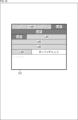
- the raw patch information and mesh information are shown, for example, as shown in box 121 in FIG. 17. Note that in FIG. 17, mesh information is shown only for patch A.
- the raw patch information indicates that the number of raw patches is 2, the number of faces in each raw patch is 4 and 2, the number of vertices in each raw patch is 8 and 4, and the number of UVs in each raw patch is 8 and 4.
- the three-dimensional coordinates (xyz) of each vertex are indicated as vertex information (v1 to v8).
- the coordinates (uv) in the texture map of each vertex are indicated as UV coordinates (vt1 to vt8).
- the edges (connections) of each face are indicated as connection information.
- the mesh information of patch A may also include attribute information such as normal vectors (normal).
- the raw patch mesh information may be in a format (hereinafter also referred to as the second format) in which the vertex coordinates of each face are shown for each connection (method 1-2-2).
- the raw patch information and mesh information may be shown, for example, as shown in square 122 in Fig. 17.
- the raw patch information indicates that the number of raw patches is 2, and the number of faces in each raw patch is 4 and 2.
- the number of vertices and UVs in each raw patch can be omitted.
- the three-dimensional coordinates (xyz) of each vertex are indicated for each connection as vertex information.
- the coordinates (uv) in the texture map of each vertex are indicated for each connection as UV coordinates (vt1 to vt8).
- the order of each vertex in the vertex information indicates the connections. In other words, this order corresponds to the connection information. Therefore, explicit indication of connection information such as that in square 121 can be omitted.
- the encoded data of the raw patch may be stored anywhere in the bit stream. For example, as shown in the seventh row from the top of the table in FIG. 14, all the raw patches may be stored in a header and encoded (method 1-2-3).
- the second encoding unit may store vertex information in a header and encode it.
- the second decoding unit may decode the encoded data of the vertex information stored in the header to generate vertex information.
- vertex information may be stored in the displacement video, and the rest may be stored in the header and encoded (method 1-2-4).
- vertex information may be packed together with the displacement vector into a two-dimensional image 131 (frame image of the displacement video).
- the three-dimensional coordinates (x, y, z) of each vertex are stored as the vertex information. That is, the coordinate value of one component (x component, y component, or z component) of one vertex is stored as one pixel value. That is, absolute information indicating the coordinates is stored in the frame image of the displacement video together with relative information such as the displacement vector.
- each component of the vertex information may be stored in a different component.
- all components of the vertex information may be stored in one component.
- the coordinate value of one component of one vertex is stored as one pixel value.
- the coordinate values (x component, y component, and z component) of one vertex are stored using three pixels.
- the second encoding unit may encode the vertex information by storing it in a displacement video whose frames are 2D images in which displacement vectors are stored.
- the displacement vector is the difference in position between the vertices of the subdivided base mesh and the vertices of the original mesh.
- the first information processing device may further include a third encoding unit that encodes the encoding method control information, which indicates the applied (selected) encoding method, by storing it in a header.
- the second decoding unit may decode the encoded data of a displacement video having frames of 2D images in which displacement vectors are stored, and generate vertex information to be stored in the displacement video.
- the displacement vector is the difference in position between the vertices of the subdivided base mesh and the vertices of the original mesh.
- the second information processing device may further include a third decoding unit that decodes the encoded data of the encoding method control information stored in the header.
- the table shown in FIG. 19 shows a comparison result of the bit rate (Mbps) of the encoded data when 11 patches are encoded using the first method and when they are encoded using the second method.
- the second method (low patch) has a smaller bit rate than the first method (Draco). Therefore, by applying the second method as in method 1, it is possible to suppress a decrease in coding efficiency. In particular, when performing sub-meshing, which is likely to result in a small number of faces, by applying the second method as in method 1, it is possible to suppress a decrease in coding efficiency.
- the first method (Draco) has a smaller bit rate than the second method (raw patch).
- the second method does not always have a smaller bit rate than the first method. Therefore, by making the encoding method selectable as in method 1-1, it is possible to suppress a decrease in encoding efficiency in a wider variety of cases.
- any method may be used for selecting (determining) this encoding method. For example, it may be selected (determined) based on the number of faces, or it may be selected (determined) by comparing the encoding costs. Note that when selecting this encoding method from pre-prepared options, the number of candidates may be any number. Furthermore, any type of encoding method may be included in the options. Furthermore, the encoding method may be selected (determined) for any data unit. For example, the encoding method may be selected (determined) for each frame, for each base mesh, or for each sub-mesh (patch).
- Embodiment ⁇ Encoding device> The present technology can be applied to an encoding device that encodes a mesh.
- Fig. 20 is a block diagram showing an example of the configuration of an encoding device, which is one aspect of an information processing device to which the present technology is applied.
- the encoding device 200 shown in Fig. 20 is a device that encodes a mesh.
- the encoding device 200 encodes a mesh in a manner basically similar to V-DMC described in Non-Patent Document 1.
- the encoding device 200 encodes the mesh by applying method 1, method 1-1, method 1-1-1, and method 1-2 described above in ⁇ 3. Encoding without conversion to secondary information>.
- the encoding device 200 may also apply one or more of methods 1-2-1 to 1-2-4. Therefore, the encoding device 200 can also be said to be a first information processing device.
- FIG. 20 shows the main processing units, data flows, etc., and is not necessarily all that is shown in FIG. 20.
- the encoding device 200 has a preprocessing unit 211, an encoding method determination unit 212, an intra encoding unit 213, an inter encoding unit 214, and a bitstream generation unit 215.
- the pre-processing unit 211 acquires a mesh and generates a base mesh and a displacement vector for each patch that corresponds to the mesh.
- the pre-processing unit 211 supplies the generated base mesh for each patch to the encoding method determination unit 212.
- the coding method determination unit 212 determines the coding method for the base mesh of each patch. For example, the coding method determination unit 212 determines whether to apply intra-coding or inter-coding, and if it is determined to apply intra-coding, selects whether to apply a first method or a second method, and generates coding method control information indicating the selected coding method (first method or second method). The coding method determination unit 212 supplies the base mesh (of the patch) to be intra-coded and the displacement vector corresponding to that base mesh, together with the coding method control information, to the intra-coding unit 213. The coding method determination unit 212 also supplies the base mesh (of the patch) to be inter-coded and the displacement vector corresponding to that base mesh to the inter-coding unit 214.
- the coding method determination unit 212 controls the intra coding unit 213 (each processing unit) so as to code the base mesh using the determined coding method. For example, when the coding method determination unit 212 selects the first method, it controls the intra coding unit 213 to code the base mesh using the first method. Also, when the coding method determination unit 212 selects the second method, it controls the intra coding unit 213 to code the base mesh using the second method.
- the intra-encoding unit 213 encodes the supplied base mesh using a method specified by the encoding method control information.
- the intra-encoding unit 213 also encodes the supplied displacement vector by storing it in a displacement video.
- the intra-encoding unit 213 supplies the generated encoded data to the bitstream generation unit 215.
- the inter-encoding unit 214 inter-encodes the supplied base mesh.
- the inter-encoding unit 214 also stores the supplied displacement vector in a displacement video and encodes it.
- the inter-encoding unit 214 supplies the generated encoded data to the bitstream generation unit 215.
- the bitstream generation unit 215 combines the encoded data of each patch supplied from the intra-encoding unit 213 and the inter-encoding unit 214 to generate one bitstream.
- the bitstream generation unit 215 outputs the generated bitstream to the outside of the encoding device 200. This bitstream is supplied to a decoder, for example, via any transmission medium or storage medium, or both.
- Fig. 21 is a block diagram showing a main configuration example of the intra-encoding unit 213 in Fig. 20.
- Fig. 21 shows main processing units, data flows, etc., and does not necessarily show everything. That is, in the intra-encoding unit 213, there may be processing units that are not shown as blocks in Fig. 21, and there may be processing and data flows that are not shown as arrows, etc. in Fig. 21.
- the intra-encoding unit 213 has a base mesh encoding unit 251, a raw patch generation unit 252, a displacement vector correction unit 253, a packing unit 254, a displacement video encoding unit 255, a mesh reconstruction unit 256, an attribute map correction unit 257, an attribute video encoding unit 258, a header encoding unit 259, and a synthesis unit 260.
- Each processing unit operates under the control of the encoding method determination unit 212.
- the base mesh encoding unit 251 acquires a base mesh and intra-encodes it using a first method. That is, the base mesh encoding unit 251 converts the base mesh into "secondary information indicating the relationship between adjacent faces" and encodes it, generating encoded data for the base mesh.
- the base mesh encoding unit 251 supplies the generated encoded data for the base mesh to the synthesis unit 260. That is, the base mesh encoding unit 251 can also be considered a first encoding unit.
- the base mesh encoding unit 251 may also decode the encoded data and generate (restore) a base mesh. This generated (restored) base mesh includes encoding distortion.
- the base mesh encoding unit 251 supplies the base mesh to the displacement vector correction unit 253 and the mesh reconstruction unit 256.
- the raw patch generation unit 252 acquires a base mesh and generates a raw patch (mesh information and raw patch information) corresponding to the base mesh.
- the raw patch generation unit 252 may generate a raw patch of the first format or a raw patch of the second format, as described with reference to FIG. 17.
- the vertex information may be stored in the header or in the displacement video.
- the raw patch generation unit 252 supplies all of the generated raw patch data to the header encoding unit 259.
- the raw patch generation unit 252 supplies the vertex information to the displacement vector correction unit 253, and supplies the other data to the header encoding unit 259.
- the displacement vector correction unit 253 acquires a base mesh including encoding distortion supplied from the base mesh encoding unit 251. Furthermore, when the second method is selected by the encoding method determination unit 212, the displacement vector correction unit 253 acquires vertex information supplied from the raw patch generation unit 252. Furthermore, the displacement vector correction unit 253 acquires a displacement vector supplied from the encoding method determination unit 212.
- the displacement vector correction unit 253 subdivides the acquired base mesh and corrects the displacement vector using the subdivided base mesh. This correction may be omitted. Furthermore, when vertex information is supplied from the raw patch generation unit 252, the displacement vector correction unit 253 may correct the vertex information using the subdivided base mesh. The displacement vector correction unit 253 supplies the displacement vector and vertex information to the packing unit 254.
- the packing unit 254 acquires the displacement vector supplied from the displacement vector correction unit 253 and packs it into a two-dimensional image of the current frame (also called a frame image). At that time, the packing unit 254 may perform coefficient transformation (e.g., wavelet transformation) on the displacement vector and pack the transformation coefficient into the two-dimensional image. The packing unit 254 may also quantize the displacement vector (or the transformation coefficient) and pack the quantized coefficient into the two-dimensional image. The packing unit 254 supplies the two-dimensional image in which the displacement vector or information equivalent thereto is packed to the displacement video encoding unit 255.
- coefficient transformation e.g., wavelet transformation
- the packing unit 254 may acquire vertex information supplied from the displacement vector correction unit 253 and pack it into a two-dimensional image of the current frame (also called a frame image). In this case, the packing unit 254 supplies the two-dimensional image in which the displacement vector or information equivalent thereto, and the vertex information or information equivalent thereto are packed to the displacement video encoding unit 255.
- the displacement video encoding unit 255 acquires the two-dimensional image supplied from the packing unit 254.
- the displacement video encoding unit 255 treats the two-dimensional image as a frame image and encodes (intra-encodes) it as a moving image (displacement video) using a 2D codec.
- the displacement video encoding unit 255 encodes the vertex information without converting it into "secondary information indicating the relationship between adjacent faces of the base mesh.” Therefore, it can also be said that the displacement video encoding unit 255 encodes the vertex information using a second method. Therefore, the displacement video encoding unit 255 can also be said to be a second encoding unit.
- the displacement video encoding unit 255 supplies the encoded data of the generated displacement video to the mesh reconstruction unit 256 and the synthesis unit 260.
- the mesh reconstruction unit 256 decodes the encoded data of the displacement video supplied from the displacement video encoding unit 255, and derives a displacement vector by unpacking from the two-dimensional image, etc.
- the mesh reconstruction unit 256 also subdivides the base mesh (including encoding distortion) supplied from the base mesh encoding unit 251, and reconstructs a mesh by applying the derived displacement vector. This mesh includes encoding distortion.
- the mesh reconstruction unit 256 supplies the reconstructed mesh to the attribute map correction unit 257.
- the attribute map correction unit 257 acquires an attribute map such as a texture, and corrects the attribute map using the mesh (including encoding distortion) supplied from the mesh reconstruction unit 256.
- the attribute map correction unit 257 supplies the corrected attribute map to the attribute video encoding unit 258. Note that this correction may be omitted.
- the attribute video encoding unit 258 converts the attribute map supplied from the attribute map correction unit 257 into frame images and encodes them as a moving image (attribute video).
- the attribute video encoding unit 258 supplies the generated encoded data of the attribute video to the synthesis unit 260.
- the header encoding unit 259 encodes the header. For example, when the encoding method determination unit 212 selects the second method, the header encoding unit 259 acquires the raw patch supplied from the raw patch generation unit 252, stores it in the header, and encodes it using the second method. For example, the header encoding unit 259 may encode the raw patch by utilizing the correlation between the vertices of the base mesh. For example, the header encoding unit 259 may differentially encode the raw patch. Also, the header encoding unit 259 may arithmetically encode the raw patch. Also, the header encoding unit 259 may perform fixed bit encoding on the raw patch.
- the header encoding unit 259 encodes the base mesh without converting it into "secondary information indicating the relationship between adjacent faces of the base mesh". Therefore, the header encoding unit 259 can also be called a second encoding unit. Note that this raw patch may or may not include vertex information.
- the header encoding unit 259 also obtains the encoding method control information supplied from the encoding method determination unit 212, stores it in the header, and encodes it. Therefore, for example, when vertex information is stored in the displacement video, the header encoding unit 259 can be said to be a third encoding unit.
- the header encoding unit 259 supplies the generated encoded data of the header to the synthesis unit 260.
- the synthesis unit 260 synthesizes (multiplexes) the supplied encoded data of the header, the encoded data of the base mesh, the encoded data of the displacement video, and the encoded data of the attribute video.
- the synthesis unit 260 supplies the synthesized encoded data to the bitstream generation unit 215.
- the encoding device 200 can encode the base mesh as described above in ⁇ 3. Encoding without conversion to secondary information>, thereby suppressing a decrease in encoding efficiency.
- step S201 the pre-processing unit 211 generates a base mesh and a displacement vector for each patch.
- step S202 the encoding method determination unit 212 determines the encoding method for the base mesh of each patch generated in step S201. For example, the encoding method determination unit 212 selects the first method or the second method as the encoding method for the base mesh of each patch generated in step S201. Then, the encoding method determination unit 212 generates encoding method control information indicating the selected encoding method.
- step S203 the intra-encoding unit 213 performs intra-encoding processing on the patch to be intra-encoded, and encodes its base mesh and displacement vector.
- step S204 the inter-encoding unit 214 performs inter-encoding processing on the patch to be inter-encoded, and encodes its base mesh and displacement vector.
- step S205 the bitstream generation unit 215 synthesizes (multiplexes) the encoded data obtained by the processing in step S203 and the encoded data obtained by the processing in step S204 to generate a bitstream.
- step S205 When step S205 is completed, the encoding process ends.
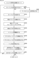
- the base mesh encoding unit 251 determines in step S251 whether or not to encode the low patch. If it is determined that the low patch is not to be encoded, the process proceeds to step S252.
- step S252 the base mesh encoding unit 251 encodes the base mesh using a first method.
- the base mesh encoding unit 251 converts the base mesh into "secondary information indicating the relationship between adjacent faces of the base mesh" and encodes it.
- step S252 When the processing of step S252 ends, the process proceeds to step S254. Also, if it is determined in step S251 that the raw patch is to be encoded, the process proceeds to step S253.
- step S253 the raw patch generator 252 converts the base mesh to generate a raw patch as information for transmission.
- step S253 the process proceeds to step S254.
- step S254 the displacement vector correction unit 253 appropriately corrects the displacement vector using a base mesh that includes coding distortion.
- step S255 the packing unit 254 packs the appropriately corrected displacement vector into a frame image of the displacement video.
- step S256 the displacement video encoding unit 255 encodes the displacement video.
- step S257 the mesh reconstruction unit 256 reconstructs the mesh using the base mesh including the coding distortion and the displacement vector.
- step S258 the attribute map correction unit 257 uses the reconstructed mesh to appropriately correct the attribute map.
- step S259 the attribute video encoding unit 258 encodes the appropriately corrected attribute map.
- step S260 the header encoding unit 259 encodes the header. If it is determined in step S251 that the raw patch is to be encoded, the header encoding unit 259 stores the raw patch generated in step S253 in the header and encodes it. In addition, the header encoding unit 259 stores the encoding method control information generated by the processing in step S202 in the header and encodes it.
- step S261 the synthesis unit 260 multiplexes the encoded data generated in each process to generate a bitstream.
- step S262 the base mesh encoding unit 251 determines whether all patches have been processed. If it is determined that there are unprocessed patches, the process returns to step S251, and subsequent processes are executed. Also, if it is determined in step S262 that all patches have been processed, the intra-encoding process ends, and the process returns to FIG. 22.
- the encoding device 200 can encode the base mesh as described above in ⁇ 3. Encoding without conversion to secondary information>, thereby preventing a decrease in encoding efficiency.
- Fig. 24 is a block diagram showing an example of the configuration of a decoding device, which is one aspect of an information processing device to which the present technology is applied.
- the decoding device 300 shown in Fig. 24 is a device that decodes mesh encoded data.
- the decoding device 300 decodes mesh encoded data in a manner basically similar to V-DMC described in Non-Patent Document 1.
- the decoding device 300 decodes the encoded data of the mesh by applying the methods 1, 1-1, 1-1-1, and 1-2 described above in ⁇ 3. Encoding without conversion to secondary information>.
- the decoding device 300 may also apply one or more of the methods 1-2-1 to 1-2-4 described above. Therefore, the decoding device 300 can also be said to be a second information processing device.
- the decoding device 300 is a decoding device corresponding to the encoding device 200 in FIG. 20, and can decode the bit stream generated by the encoding device 200 and reconstruct a mesh.
- FIG. 24 shows the main processing units, data flows, etc., and is not necessarily all that is shown in FIG. 24.
- processing units that are not shown as blocks in FIG. 24, and there may be processing and data flows that are not shown as arrows, etc. in FIG. 24.
- the decoding device 300 has a demultiplexing unit 311, a header decoding unit 312, an intra decoding unit 313, an inter decoding unit 314, and a synthesis unit 315.
- the decoding device 300 is supplied with a bitstream generated by an encoding device (e.g., encoding device 200) that encodes the mesh using the V-DMC method.
- an encoding device e.g., encoding device 200
- the demultiplexing unit 311 demultiplexes the bitstream and extracts each piece of coded data contained in the bitstream. For example, the demultiplexing unit 311 extracts header coded data from the bitstream and supplies it to the header decoding unit 312. Based on the control of the header decoding unit 312, the demultiplexing unit 311 also supplies coded data of patches in which the base mesh is intra-coded to the intra decoding unit 313, and supplies coded data of patches in which the base mesh is inter-coded to the inter decoding unit 314.
- the header decoding unit 312 decodes the encoded data of the header supplied from the demultiplexing unit 311, and supplies necessary information to the demultiplexing unit 311, the intra decoding unit 313, and the inter decoding unit 314 as appropriate.
- the header decoding unit 312 also controls the operation of the demultiplexing unit 311, the intra decoding unit 313, and the inter decoding unit 314.
- the header decoding unit 312 also decodes the encoded data of the encoding method control information and generates (restores) the encoding method control information. Therefore, the header decoding unit 312 can also be considered a third decoding unit.
- the header decoding unit 312 supplies the encoding method control information to the intra decoding unit 313.
- the header decoding unit 312 obtains the encoded data of the raw patch stored in the header, decodes it using the second method, and generates (restores) the raw patch.
- the header decoding unit 312 generates a base mesh that is not converted into secondary information indicating the relationship between adjacent faces of the base mesh. Therefore, the header decoding unit 312 can also be called a second decoding unit.
- This encoded data may be encoded using the correlation between the vertices of the base mesh. For example, the header decoding unit 312 may differentially decode the encoded data of the raw patch that has been differentially encoded.
- the header decoding unit 312 may also arithmetically decode the encoded data of the raw patch that has been arithmetically encoded.
- the header decoding unit 312 may also fixed-bit decode the encoded data of the raw patch that has been fixed-bit encoded.
- the header decoding unit 312 supplies the generated (restored) raw patch to the intra decoding unit 313.
- the intra-decoding unit 313 obtains the coded data of the intra-coded patch from the demultiplexing unit 311 and performs intra-decoding under the control of the header decoding unit 312. At that time, the intra-decoding unit 313 decodes the coded data by applying the coding method specified by the coding method control information supplied from the header decoding unit 312. The intra-decoding unit 313 supplies the mesh and attribute map of the patch generated (reconstructed) by the decoding to the synthesis unit 315.
- the inter decoding unit 314 Based on the control of the header decoding unit 312, the inter decoding unit 314 obtains the coded data of the inter coded patch from the demultiplexing unit 311, performs inter decoding, generates (restores) the mesh and attribute map of the patch, and supplies them to the synthesis unit 315.
- the synthesis unit 315 synthesizes the meshes and attribute maps of each patch supplied from the intra-decoding unit 313 and the inter-decoding unit 314, and generates and outputs a mesh and attribute map for the entire object.
- Fig. 25 is a block diagram showing a main example configuration of the intra decoder 313 in Fig. 24.
- Fig. 25 shows main processing units, data flows, etc., and does not necessarily show everything. That is, in the intra decoder 313, there may be processing units not shown as blocks in Fig. 25, and there may be processing and data flows not shown as arrows, etc. in Fig. 25.
- the intra-decoding unit 313 has a displacement video decoding unit 351, an unpacking unit 352, a base mesh decoding unit 353, a reconstruction unit 354, a subdivision unit 355, a displacement vector application unit 356, and an attribute video decoding unit 357.
- Each processing unit operates under the control of the header decoding unit 312.
- the displacement video decoding unit 351 decodes the encoded data of the displacement video supplied from the demultiplexing unit 311, and generates (restores) the displacement video. Note that raw patches (vertex information) may be stored in this displacement video. In that case, it can also be said that the displacement video decoding unit 351 decodes the encoded data of the displacement video, and generates the vertex information to be stored in the displacement video. Therefore, the displacement video decoding unit 351 can also be said to be a second decoding unit.
- the displacement video decoding unit 351 supplies the generated displacement video (the current frame) to the unpacking unit 352.
- the unpacking unit 352 unpacks (extracts) a displacement vector from the current frame of the displacement video supplied from the displacement video decoding unit 351.
- the unpacking unit 352 may unpack a transform coefficient and perform coefficient transformation (e.g., wavelet transformation) on the transform coefficient to derive a displacement vector.
- the unpacking unit 352 may also unpack a quantized coefficient and dequantize the quantized coefficient to derive a displacement vector.
- the unpacking unit 352 may also unpack a quantized coefficient and dequantize the quantized coefficient to derive a transform coefficient, and perform coefficient transformation (e.g., wavelet transformation) on the transform coefficient to derive a displacement vector.
- the unpacking unit 352 supplies the unpacked displacement vector to the displacement vector application unit 356.
- the unpacking unit 352 also unpacks the vertex information and supplies it to the reconstruction unit 354.
- the base mesh decoding unit 353 obtains the coding method control information supplied from the header decoding unit 312.
- the base mesh decoding unit 353 decodes the coded data of the base mesh supplied from the demultiplexing unit 311 using the first method, and generates (restores) the base mesh.
- the base mesh decoding unit 353 decodes the coded data of the base mesh, generates secondary information indicating the relationship between adjacent faces of the base mesh, and converts the generated secondary information into vertex information and connection information of the base mesh. Therefore, the base mesh decoding unit 353 can also be called a first decoding unit.
- the base mesh decoding unit 353 supplies the generated base mesh to the subdivision unit 355.
- the reconstruction unit 354 acquires the coding method control information supplied from the header decoding unit 312. If the coding method control information specifies the second method, the reconstruction unit 354 acquires the raw patch (the raw patch included in the header) supplied from the header decoding unit 312. As described above, the vertex information constituting the raw patch may be stored in the header or in the displacement video. If the vertex information is stored in the displacement video, the reconstruction unit 354 further acquires the vertex information supplied from the unpacking unit 352. The reconstruction unit 354 reconstructs the base mesh using the raw patch acquired in this manner. In other words, the reconstruction unit 354 converts the raw patch, which is information for transmission, into a base mesh. The data format of this raw patch may be the first format, the second format, or another format. The reconstruction unit 354 supplies the reconstructed base mesh to the subdivision unit 355.
- the subdivision unit 355 subdivides the base mesh supplied from the base mesh decoding unit 353, and supplies the subdivided base mesh to the displacement vector application unit 356.
- the subdivision unit 355 also subdivides the base mesh supplied from the reconstruction unit 354, and supplies the subdivided base mesh to the displacement vector application unit 356.
- the displacement vector application unit 356 applies the displacement vectors supplied from the unpacking unit 352 to the vertices of the subdivided base mesh supplied from the subdivision unit 355, and reconstructs the mesh.
- this reconstructed mesh is also referred to as a decoded mesh.
- the displacement vector application unit 356 generates a decoded mesh.
- the displacement vector application unit 356 supplies the generated decoded mesh to the synthesis unit 315.
- the attribute video decoding unit 357 decodes the encoded data of the attribute video supplied from the demultiplexing unit 311 and generates the attribute video (the current frame).
- the attribute video decoding unit 357 supplies the generated current frame of the attribute video, i.e., the attribute map corresponding to the decoded mesh, to the synthesis unit 315.
- the decoding device 300 can decode the coded data of the base mesh as described above in ⁇ 3. Coding without conversion to secondary information>, thereby suppressing a decrease in coding efficiency.
- step S301 the demultiplexer 311 demultiplexes the bit stream and extracts various encoded data.
- the header decoding unit 312 decodes the coded data of the header extracted in step S301, and generates (restores) information to be stored in the header. For example, the header decoding unit 312 decodes the coded data of the coding method control information, and generates (restores) the coding method control information. Furthermore, when the coding method control information specifies the second method, the header decoding unit 312 obtains the coded data of the raw patch stored in the header, decodes it using the second method, and generates (restores) the raw patch. In other words, the header decoding unit 312 generates a base mesh that has not been converted into secondary information indicating the relationship between adjacent faces of the base mesh.
- step S303 the intra-decoding unit 313 executes intra-decoding processing and intra-decodes the encoded data of the intra-coded patch.
- step S304 the inter-decoding unit 314 executes an inter-decoding process to inter-decode the coded data of the inter-coded patch.
- step S305 the synthesis unit 315 synthesizes the 3D data of each patch generated by the processing in steps S303 and S304.
- step S305 When the processing of step S305 is completed, the decoding process ends.
- step S351 the displacement video decoding unit 351 decodes the encoded data of the displacement video and generates (restores) the displacement video. Note that raw patches (vertex information) may be stored in this displacement video. In that case, it can be said that the displacement video decoding unit 351 decodes the encoded data of the displacement video and generates vertex information to be stored in the displacement video.
- the unpacking unit 352 unpacks (extracts) a displacement vector from the current frame of the displacement video.
- the unpacking unit 352 may unpack a transform coefficient and perform coefficient transformation (e.g., wavelet transformation) on the transform coefficient to derive a displacement vector.
- the unpacking unit 352 may also unpack a quantized coefficient and dequantize the quantized coefficient to derive a displacement vector.
- the unpacking unit 352 may also unpack a quantized coefficient and dequantize the quantized coefficient to derive a transform coefficient, and perform coefficient transformation (e.g., wavelet transformation) on the transform coefficient to derive a displacement vector. Note that if raw patches (vertex information) are stored in this displacement video, the unpacking unit 352 also unpacks the vertex information.
- step S353 the base mesh decoding unit 353 determines whether or not to decode the low patch. If the encoding method control information specifies the first method, it is determined that the low patch is not to be decoded, and the process proceeds to step S354.
- step S354 the base mesh decoding unit 353 decodes the coded data of the base mesh extracted from the bit stream by the demultiplexing in step S301 using the first method, and generates (restores) the base mesh.
- the base mesh decoding unit 353 decodes the coded data of the base mesh, generates secondary information indicating the relationship between adjacent faces of the base mesh, and converts the generated secondary information into vertex information and connection information of the base mesh.
- step S354 When the processing of step S354 ends, the process proceeds to step S356. Also, in step S353, if the encoding method control information specifies the second method, it is determined that the raw patch is to be decoded, and the process proceeds to step S355.
- step S355 the reconstruction unit 354 acquires the raw patch (the raw patch stored in the header and transmitted) generated (restored) by the processing of step S302.
- the vertex information constituting the raw patch may be stored in the header or in the displacement video.
- the reconstruction unit 354 further acquires the vertex information unpacked from the displacement video.
- the reconstruction unit 354 reconstructs the base mesh using the raw patch acquired in this manner. In other words, the reconstruction unit 354 converts the raw patch, which is information for transmission, into a base mesh.
- the data format of this raw patch may be the first format, the second format, or another format.
- step S356 the subdivision unit 355 subdivides the base mesh obtained in step S354 or step S355.
- step S357 the displacement vector application unit 356 applies the displacement vectors unpacked from the displacement video to the vertices of the subdivided base mesh to reconstruct the mesh (generate a decoded mesh).
- step S358 the attribute video decoding unit 357 decodes the encoded data of the attribute video extracted from the bitstream by the demultiplexing in step S301, and generates the attribute video (the current frame).
- step S359 the base mesh decoding unit 353 determines whether all patches have been processed. If it is determined that there are unprocessed patches, the process returns to step S351, and subsequent processes are executed. Also, if it is determined in step S359 that all patches have been processed, the intra-decoding process ends, and the process returns to FIG. 26.
- the decoding device 300 can decode the coded data of the base mesh as described above in ⁇ 3. Coding without conversion to secondary information>, thereby preventing a decrease in coding efficiency.
- the above-mentioned series of processes can be executed by hardware or software.
- the programs constituting the software are installed in a computer.
- the computer includes a computer built into dedicated hardware, and a general-purpose personal computer, etc., capable of executing various functions by installing various programs.
- FIG. 28 is a block diagram showing an example of the hardware configuration of a computer that executes the above-mentioned series of processes using a program.
- a CPU Central Processing Unit
- ROM Read Only Memory
- RAM Random Access Memory
- An input/output interface 910 Also connected to the bus 904 is an input/output interface 910.
- An input unit 911, an output unit 912, a memory unit 913, a communication unit 914, and a drive 915 are connected to the input/output interface 910.
- the input unit 911 includes, for example, a keyboard, a mouse, a microphone, a touch panel, an input terminal, etc.
- the output unit 912 includes, for example, a display, a speaker, an output terminal, etc.
- the storage unit 913 includes, for example, a hard disk, a RAM disk, a non-volatile memory, etc.
- the communication unit 914 includes, for example, a network interface.
- the drive 915 drives removable media 921 such as a magnetic disk, an optical disk, a magneto-optical disk, or a semiconductor memory.
- the CPU 901 loads a program stored in the storage unit 913, for example, into the RAM 903 via the input/output interface 910 and the bus 904, and executes the program, thereby carrying out the above-mentioned series of processes.
- the RAM 903 also stores data necessary for the CPU 901 to execute various processes, as appropriate.
- the program executed by the computer can be applied by recording it on removable media 921 such as package media, for example.
- the program can be installed in the storage unit 913 via the input/output interface 910 by inserting the removable media 921 into the drive 915.
- the program can also be provided via a wired or wireless transmission medium, such as a local area network, the Internet, or digital satellite broadcasting. In that case, the program can be received by the communication unit 914 and installed in the storage unit 913.
- a wired or wireless transmission medium such as a local area network, the Internet, or digital satellite broadcasting.
- the program can be received by the communication unit 914 and installed in the storage unit 913.
- this program can also be pre-installed in the ROM 902 or memory unit 913.
- the present technology may be applied to any configuration, for example, to various electronic devices.
- the present technology can be implemented as part of an apparatus, such as a processor (e.g., a video processor) as a system LSI (Large Scale Integration), a module using multiple processors (e.g., a video module), a unit using multiple modules (e.g., a video unit), or a set in which other functions are added to a unit (e.g., a video set).
- a processor e.g., a video processor
- system LSI Large Scale Integration
- modules using multiple processors e.g., a video module
- a unit using multiple modules e.g., a video unit
- a set in which other functions are added to a unit e.g., a video set.
- the present technology can also be applied to a network system consisting of multiple devices.
- the present technology may be implemented as cloud computing in which multiple devices share and collaborate on processing via a network.
- the present technology may be implemented in a cloud service that provides image (video) related services to any terminal, such as a computer, AV (Audio Visual) equipment, portable information processing terminal, IoT (Internet of Things) device, etc.
- a system refers to a collection of multiple components (devices, modules (parts), etc.), regardless of whether all the components are in the same housing. Therefore, multiple devices housed in separate housings and connected via a network, and a single device in which multiple modules are housed in a single housing, are both systems.
- Systems, devices, processing units, etc. to which the present technology is applied can be used in any field, for example, transportation, medical care, crime prevention, agriculture, livestock farming, mining, beauty, factories, home appliances, weather, nature monitoring, etc.
- the applications thereof are also arbitrary.
- a "flag” refers to information for identifying multiple states, and includes not only information used to identify two states, true (1) or false (0), but also information capable of identifying three or more states.
- the value that this "flag” can take may be, for example, two values, 1/0, or three or more values. That is, the number of bits constituting this "flag” is arbitrary, and may be one bit or multiple bits.
- identification information including flags
- identification information includes flags
- “flag” and “identification information” include not only the information itself, but also difference information with respect to the reference information.
- various information (metadata, etc.) related to the encoded data may be transmitted or recorded in any form as long as it is associated with the encoded data.
- the term "associate” means, for example, making one piece of data available (linked) when processing the other piece of data.
- data associated with each other may be combined into one piece of data, or each piece of data may be individual data.
- information associated with encoded data (image) may be transmitted on a transmission path different from that of the encoded data (image).
- information associated with encoded data (image) may be recorded on a recording medium different from that of the encoded data (image) (or on a different recording area of the same recording medium).
- this "association" may be a part of the data, not the entire data.
- an image and information corresponding to that image may be associated with each other in any unit, such as multiple frames, one frame, or a part of a frame.
- the configuration described above as one device (or processing unit) may be divided and configured as multiple devices (or processing units).
- the configurations described above as multiple devices (or processing units) may be combined and configured as one device (or processing unit).
- configurations other than those described above may be added to the configuration of each device (or processing unit).
- part of the configuration of one device (or processing unit) may be included in the configuration of another device (or other processing unit).
- the above-mentioned program may be executed in any device.
- the device has the necessary functions (functional blocks, etc.) and is capable of obtaining the necessary information.
- each step of a single flowchart may be executed by a single device, or may be shared among multiple devices.
- the multiple processes may be executed by a single device, or may be shared among multiple devices.
- multiple processes included in a single step may be executed as multiple step processes.
- processes described as multiple steps may be executed collectively as a single step.
- the processing of the steps describing a program executed by a computer may be executed chronologically in the order described in this specification, or may be executed in parallel, or individually at the required timing, such as when a call is made. In other words, as long as no contradiction arises, the processing of each step may be executed in an order different from the order described above. Furthermore, the processing of the steps describing this program may be executed in parallel with the processing of other programs, or may be executed in combination with the processing of other programs.
- the multiple technologies related to the present technology can be implemented independently and individually, so long as no contradictions arise.
- any multiple of the present technologies can also be implemented in combination.
- part or all of the present technology described in any embodiment can be implemented in combination with part or all of the present technology described in another embodiment.
- part or all of any of the present technologies described above can be implemented in combination with other technologies not described above.
- the present technology can also be configured as follows.
- the base mesh is a mesh that is coarser than an original mesh to be encoded, the original mesh being composed of vertices and connections that represent a three-dimensional structure of an object, and is generated by thinning out the vertices from the original mesh.
- the information processing device further stores encoding method control information indicating the selected encoding method in the header and performs encoding.
- the second encoding unit encodes the vertex information by storing it in a displacement video having a 2D image in which a displacement vector is stored as a frame,
- the information processing device according to any one of (1) to (4), wherein the displacement vector is a difference in position between the vertices of the subdivided base mesh and the vertices of the original mesh.
- the information processing device further comprising: a third encoding unit that stores, in a header, encoding method control information indicating the selected encoding method and encodes the encoding method.
- a raw patch generating unit converts the base mesh to generate a raw patch as information for transmission, The information processing device according to any one of (1) to (9), wherein, when the second method is selected as the encoding method, the second encoding unit encodes the raw patch without converting it into the secondary information.
- the raw patch includes mesh information including the vertex information and the connectivity information, and raw patch information consisting of meta information regarding the base mesh.
- the vertex information omits duplicate information and the vertices are represented by a minimum number of vertices.
- the vertex information indicates the vertex for each of the connections.
- the information processing device according to any one of (11) to (13), wherein the raw patch information includes information indicating the number of the raw patches and information indicating the number of faces in the raw patch.
- the raw patch information includes information indicating the number of the raw patches and information indicating the number of faces in the raw patch.
- the first method is selected as the encoding method
- vertex information indicating the positions of the vertices constituting the base mesh and connection information indicating the connections between the vertices constituting the base mesh are converted into secondary information indicating the relationship between adjacent faces of the base mesh, and encoded
- the vertex information and the connection information are encoded without being converted into the secondary information
- the base mesh is a mesh that is coarser than an original mesh to be encoded, the original mesh being composed of vertices and connections that represent a three-dimensional structure of an object, and is generated by thinning out the vertice
- a method for encoding a base mesh comprising: a first decoding unit that, when the encoding method control information indicates a first method as an encoding method for the intra-encoded base mesh, decodes encoded data of the base mesh, generates secondary information indicating a relationship between adjacent faces of the base mesh, and converts the generated secondary information into vertex information and connection information of the base mesh; and a second decoding unit that, when the encoding method control information indicates a second method as the encoding method, decodes encoded data of the base mesh, and generates the vertex information and the connection information that are not converted into the secondary information
- the base mesh is a mesh that is coarser than an original mesh to be encoded, the original mesh being composed of vertices and connections that represent a three-dimensional structure of an object, and is generated by thinning out the vertices from the original mesh;
- the vertex information is information indicating positions of vertices constituting the base mesh
- the connection information is information indicating connections between the
- the information processing device further comprising: a third decoding unit that decodes the encoded data of the encoding method control information stored in a header.
- the second decoding unit decodes the encoded data of the base mesh and generates a raw patch which is information of the transmission format of the base mesh;
- the information processing device according to any one of (21) to (29), further comprising a reconstruction unit that reconstructs the base mesh using the raw patch.
- the raw patch includes mesh information including the vertex information and the connectivity information, and raw patch information consisting of meta information regarding the base mesh.
- the information processing device in which duplicate information is omitted from the vertex information, and the vertices are represented by a minimum number of vertices. (33) The information processing device according to (31), wherein the vertex information indicates the vertex for each of the connections. (34) The information processing device according to any one of (31) to (33), wherein the raw patch information includes information indicating the number of the raw patches and information indicating the number of faces in the raw patch.
- the coding scheme control information indicates a first scheme as the coding scheme of the intra-coded base mesh, decoding the coded data of the base mesh, generating secondary information indicating a relationship between adjacent faces of the base mesh, and converting the generated secondary information into vertex information and connection information of the base mesh; If the encoding method control information indicates a second method as the encoding method, decoding the encoded data of the base mesh to generate the vertex information and the connection information that have not been converted into the secondary information;
- the base mesh is a mesh that is coarser than an original mesh to be encoded, the original mesh being composed of vertices and connections that represent a three-dimensional structure of an object, and is generated by thinning out the vertices from the original mesh;
- the vertex information is information indicating positions of vertices constituting the base mesh,
- the connection information is information indicating connections between the vertices constituting the base mesh, and the first method is an encoding method for converting the vertex information and the connection information into the secondary
Landscapes
- Engineering & Computer Science (AREA)
- Physics & Mathematics (AREA)
- Multimedia (AREA)
- General Physics & Mathematics (AREA)
- Theoretical Computer Science (AREA)
- Signal Processing (AREA)
- Computer Graphics (AREA)
- Geometry (AREA)
- Software Systems (AREA)
- Compression, Expansion, Code Conversion, And Decoders (AREA)
- Compression Or Coding Systems Of Tv Signals (AREA)
Abstract
Description
1.技術内容・技術用語をサポートする文献等
2.ベースメッシュのイントラ符号化
3.2次情報に変換しない符号化
4.実施の形態
5.付記
本技術で開示される範囲は、実施の形態に記載されている内容だけではなく、出願当時において公知となっている以下の非特許文献等に記載されている内容や以下の非特許文献において参照されている他の文献の内容等も含まれる。
<V-DMC>
従来、立体構造物(3次元形状のオブジェクト)の3次元構造を表す3Dデータとして、頂点および接続によりポリゴンを形成することによりオブジェクト表面の3次元形状を表現するメッシュ(Mesh)があった。
ベースメッシュの符号化方法として、フレーム毎に独立に符号化するイントラ符号化と、フレーム間の相関を利用して符号化するインター符号化がある。イントラ符号化として、例えばDracoなどのように、隣接するフェイスを参照する符号化方式が提案されている。このような符号化方式では、ベースメッシュを構成する頂点の位置を示す頂点情報や、ベースメッシュを構成する頂点間の接続を示す接続情報が、「互いに隣接するフェイス同士の関係性を示す2次情報」に変換されて符号化される。
例えばDracoのように隣接するフェイスを参照する符号化方式を用いて符号化した場合のビット量を3つのケースで比較する。1つ目のケースでは、図12の左に示されるように、1つのパッチ61を1回で符号化する。2つ目のケースでは、図12の中央に示されるように、1つのパッチ61をパッチA乃至パッチCに3分割し、それらのパッチをまとめて(マージして)1回で符号化する。3つ目のケースでは、図12の右に示されるように、1つのパッチ61をパッチA乃至パッチCに3分割し、パッチ61-1(パッチA)、パッチ61-2(パッチB)、パッチ61-3(パッチC)をそれぞれ独立に符号化する。
<方法1>
そこで、ベースメッシュをイントラ符号化する場合、ベースメッシュの頂点情報および接続情報を「隣接するフェイスを参照する符号化方式」とは異なる符号化方式で符号化する。例えば、図14の表の最上段に示されるように、ベースメッシュの頂点情報および接続情報を「互いに隣接するフェイス同士の関係性を示す2次情報」に変換せずに符号化する(方法1)。
この方法1が適用される場合、例えば、図14の表の上から2段目に示されるように、符号化方式を選択し、選択した符号化方式で符号化してもよい(方法1-1)。つまり、イントラ符号化するベースメッシュの符号化方式を決定するようにし(符号化方式を可変とし)、その符号化方式として、ベースメッシュの頂点情報および接続情報を「互いに隣接するフェイス同士の関係性を示す2次情報」に変換せずに符号化する符号化方式を適用することができるようにしてもよい。
なお、この第2の方式において、ベースメッシュの頂点情報および接続情報は、「互いに隣接するフェイス同士の関係性を示す2次情報」に変換されなければ、どのように符号化および復号されてもよい。
このように符号化方式を可変とする場合、エンコーダおよびデコーダにおいて、互いに同一の符号化方式が適用されるようにすればよい。
この符号化方式制御情報は、エンコーダにおいて適用された符号化方式を示すものであればどのような情報であってもよい。例えば、符号化方式制御情報が、適用された符号化方式を示すインデックスを含んでもよい。例えば、第1の方式が適用された場合、第1の方式を示すインデックス(例えば0)が符号化方式制御情報として伝送され、第2の方式が適用された場合、第2の方式を示すインデックス(例えば1)が符号化方式制御情報として伝送されてもよい。
上述のように、ベースメッシュの頂点情報および接続情報を「互いに隣接するフェイス同士の関係性を示す2次情報」に変換せずに符号化する符号化方式で符号化する場合、ベースメッシュは、伝送用情報(ローパッチ(RAW patch))に変換してもよい。例えば、図14の表の上から4段目に示されるように、ベースメッシュからローパッチが生成され、そのローパッチが符号化されてもよい(方法1-2)。ローパッチは、ベースメッシュの伝送用の情報であり、一般的なベースメッシュとデータ形式が異なるものの、頂点情報や接続情報をそのまま示す情報であり、ベースメッシュの互いに隣接するフェイス同士の関係性を示す情報ではない。
次に、このローパッチのデータについて説明する。このローパッチのデータは、ベースメッシュの頂点情報および接続情報を含むメッシュ情報と、そのベースメッシュに関するメタ情報からなるローパッチ情報とを含む。メッシュ情報には、UV座標(頂点とテクスチャとの対応関係を示す情報)がさらに含まれてもよい。また、メッシュ情報には、例えば法線ベクトル等の属性情報がさらに含まれてもよい。ローパッチ情報には、ローパッチの数を示す情報が含まれてもよい。また、ローパッチ情報には、各ローパッチ内のフェイス数を示す情報が含まれてもよい。また、ローパッチ情報には、各ローパッチ内の頂点数を示す情報が含まれてもよい。また、ローパッチ情報には、各ローパッチ内のUV座標の数(UV数とも称する)を示す情報が含まれてもよい。また、ローパッチ情報には、各ローパッチ内の属性情報の数(例えば法線ベクトルの数)等が含まれてもよい。
ローパッチ(メッシュ情報およびローパッチ情報)のデータ形式はどのような形式であってもよい。例えば、図14の表の上から5段目に示されるように、ローパッチのメッシュ情報において、重複情報が省略され、各要素(例えば頂点情報等)が最小数で示される形式(以下において第1の形式とも称する)であってもよい(方法1-2-1)。
また、図14の表の上から6段目に示されるように、ローパッチのメッシュ情報において、各フェイスの頂点座標等が接続毎に示される形式(以下において第2の形式とも称する)であってもよい(方法1-2-2)。つまり、図16のパッチAおよびパッチBについて、ローパッチ情報およびメッシュ情報を、例えば図17の四角122内のように示してもよい。
ローパッチの符号化データは、ビットストリームのどこに格納されてもよい。例えば、図14の表の上から7段目に示されるように、ローパッチを全てヘッダに格納して符号化してもよい(方法1-2-3)。例えば、上述の第1の情報処理装置において、第2の符号化部が、頂点情報をヘッダに格納して符号化してもよい。また、上述の第2の情報処理装置において、第2の復号部が、ヘッダに格納される頂点情報の符号化データを復号し、頂点情報を生成してもよい。
また、例えば、図14の表の最下段に示されるように、頂点情報を変位ビデオに格納し、その他をヘッダに格納して符号化してもよい(方法1-2-4)。例えば、図18に示されるように、頂点情報が変位ベクトルとともに2次元画像131(変位ビデオのフレーム画像)にパッキングされてもよい。その場合、頂点情報として各頂点の3次元座標(x,y,z)が格納される。つまり、1つの頂点の1成分(x成分、y成分、またはz成分)の座標値が1つの画素値として格納される。つまり、変位ビデオのフレーム画像に、変位ベクトルのような相対情報とともに、座標を示す絶対情報が格納される。
図19に示される表は、11個のパッチを第1の方式を用いて符号化した場合と第2の方式を用いて符号化した場合とで符号化データのビットレート(Mbps)の比較結果を示す。
上述した各種方法(方法1、方法1-1、方法1-1-1、方法1-2、方法1-2-1、方法1-2-2、方法1-2-3、方法1-2-4、および、これら以外の上述した方法)は、適宜、組み合わせて適用してもよい。
<符号化装置>
本技術は、メッシュを符号化する符号化装置に適用することができる。図20は、本技術を適用した情報処理装置の一態様である符号化装置の構成の一例を示すブロック図である。図20に示される符号化装置200は、メッシュを符号化する装置である。符号化装置200は、非特許文献1に記載のV-DMCと基本的に同様の方法でメッシュを符号化する。
図21は、図20のイントラ符号化部213の主な構成例を示すブロック図である。図21においては、処理部やデータの流れ等の主なものを示しており、図21に示されるものが全てとは限らない。つまり、イントラ符号化部213において、図21においてブロックとして示されていない処理部が存在したり、図21において矢印等として示されていない処理やデータの流れが存在したりしてもよい。
この符号化装置200により実行される符号化処理の流れの例を、図22のフローチャートを参照して説明する。
次に、図22のステップS203において実行されるイントラ符号化処理の流れの例を、図23のフローチャートを参照して説明する。
本技術は、メッシュの符号化データを復号する復号装置に適用することができる。図24は、本技術を適用した情報処理装置の一態様である復号装置の構成の一例を示すブロック図である。図24に示される復号装置300は、メッシュの符号化データを復号する装置である。復号装置300は、非特許文献1に記載のV-DMCと基本的に同様の方法でメッシュの符号化データを復号する。
図25は、図24のイントラ復号部313の主な構成例を示すブロック図である。図25においては、処理部やデータの流れ等の主なものを示しており、図25に示されるものが全てとは限らない。つまり、イントラ復号部313において、図25においてブロックとして示されていない処理部が存在したり、図25において矢印等として示されていない処理やデータの流れが存在したりしてもよい。
この復号装置300により実行される復号処理の流れの例を、図26のフローチャートを参照して説明する。
次に、図26のステップS303において実行されるイントラ復号処理の流れの例を、図27のフローチャートを参照して説明する。
<コンピュータ>
上述した一連の処理は、ハードウエアにより実行させることもできるし、ソフトウエアにより実行させることもできる。一連の処理をソフトウエアにより実行する場合には、そのソフトウエアを構成するプログラムが、コンピュータにインストールされる。ここでコンピュータには、専用のハードウエアに組み込まれているコンピュータや、各種のプログラムをインストールすることで、各種の機能を実行することが可能な、例えば汎用のパーソナルコンピュータ等が含まれる。
本技術は、任意の構成に適用することができる。例えば、本技術は、様々な電子機器に適用され得る。
本技術を適用したシステム、装置、処理部等は、例えば、交通、医療、防犯、農業、畜産業、鉱業、美容、工場、家電、気象、自然監視等、任意の分野に利用することができる。また、その用途も任意である。
なお、本明細書において「フラグ」とは、複数の状態を識別するための情報であり、真(1)または偽(0)の2状態を識別する際に用いる情報だけでなく、3以上の状態を識別することが可能な情報も含まれる。したがって、この「フラグ」が取り得る値は、例えば1/0の2値であってもよいし、3値以上であってもよい。すなわち、この「フラグ」を構成するbit数は任意であり、1bitでも複数bitでもよい。また、識別情報(フラグも含む)は、その識別情報をビットストリームに含める形だけでなく、ある基準となる情報に対する識別情報の差分情報をビットストリームに含める形も想定されるため、本明細書においては、「フラグ」や「識別情報」は、その情報だけではなく、基準となる情報に対する差分情報も包含する。
(1) イントラ符号化するベースメッシュの符号化方式として第1の方式または第2の方式を選択する符号化方式決定部と、
前記符号化方式として前記第1の方式が選択された場合、前記ベースメッシュを構成する頂点の位置を示す頂点情報と、前記ベースメッシュを構成する前記頂点間の接続を示す接続情報とを、前記ベースメッシュの互いに隣接するフェイス同士の関係性を示す2次情報に変換して符号化する第1の符号化部と、
前記符号化方式として前記第2の方式が選択された場合、前記頂点情報および前記接続情報を前記2次情報に変換せずに符号化する第2の符号化部と
を備え、
前記ベースメッシュは、オブジェクトの3次元構造を表現する頂点および接続により構成される符号化対象のオリジナルメッシュから前記頂点を間引くことにより生成される、前記オリジナルメッシュよりも粗いメッシュである
情報処理装置。
(2) 前記第2の符号化部は、前記ベースメッシュの頂点間の相関を利用して、前記頂点情報を符号化する
(1)に記載の情報処理装置。
(3) 前記第2の符号化部は、前記頂点情報を差分符号化する
(2)に記載の情報処理装置。
(4) 前記第2の符号化部は、前記頂点情報を算術符号化する
(2)に記載の情報処理装置。
(5) 前記第2の符号化部は、前記頂点情報を固定ビット符号化する
(1)に記載の情報処理装置。
(6) 前記第2の符号化部は、前記頂点情報をヘッダに格納して符号化する
(1)乃至(5)のいずれかに記載の情報処理装置。
(7) 前記第2の符号化部は、さらに、選択された前記符号化方式を示す符号化方式制御情報を前記ヘッダに格納して符号化する
(6)に記載の情報処理装置。
(8) 前記第2の符号化部は、前記頂点情報を、変位ベクトルが格納された2D画像をフレームとする変位ビデオに格納して符号化し、
前記変位ベクトルは、細分化された前記ベースメッシュの前記頂点と前記オリジナルメッシュの前記頂点との間の位置の差である
(1)乃至(4)のいずれかに記載の情報処理装置。
(9) 選択された前記符号化方式を示す符号化方式制御情報をヘッダに格納して符号化する第3の符号化部をさらに備える
(8)に記載の情報処理装置。
(10) 前記ベースメッシュを変換して伝送用情報としてローパッチを生成するローパッチ生成部をさらに備え、
前記第2の符号化部は、前記符号化方式として前記第2の方式が選択された場合、前記ローパッチを前記2次情報に変換せずに符号化する
(1)乃至(9)のいずれかに記載の情報処理装置。
(11) 前記ローパッチは、前記頂点情報および前記接続情報を含むメッシュ情報と、前記ベースメッシュに関するメタ情報からなるローパッチ情報とを含む
(10)に記載の情報処理装置。
(12) 前記頂点情報は、重複情報が省略され、前記頂点が最小数で示される
(11)に記載の情報処理装置。
(13) 前記頂点情報は、前記頂点が前記接続毎に示される
(11)に記載の情報処理装置。
(14) 前記ローパッチ情報は、前記ローパッチの数を示す情報と、前記ローパッチ内のフェイス数を示す情報とを含む
(11)乃至(13)のいずれかに記載の情報処理装置。
(15) イントラ符号化するベースメッシュの符号化方式として第1の方式または第2の方式を選択し、
前記符号化方式として前記第1の方式が選択された場合、前記ベースメッシュを構成する頂点の位置を示す頂点情報と、前記ベースメッシュを構成する前記頂点間の接続を示す接続情報とを、前記ベースメッシュの互いに隣接するフェイス同士の関係性を示す2次情報に変換して符号化し、
前記符号化方式として前記第2の方式が選択された場合、前記頂点情報および前記接続情報を前記2次情報に変換せずに符号化し、
前記ベースメッシュは、オブジェクトの3次元構造を表現する頂点および接続により構成される符号化対象のオリジナルメッシュから前記頂点を間引くことにより生成される、前記オリジナルメッシュよりも粗いメッシュである
情報処理方法。
を備え、
前記ベースメッシュは、オブジェクトの3次元構造を表現する頂点および接続により構成される符号化対象のオリジナルメッシュから前記頂点を間引くことにより生成される、前記オリジナルメッシュよりも粗いメッシュであり、
前記頂点情報は、前記ベースメッシュを構成する頂点の位置を示す情報であり、
前記接続情報は、前記ベースメッシュを構成する前記頂点間の接続を示す情報であり、 前記第1の方式は、前記頂点情報および前記接続情報を前記2次情報に変換して符号化する符号化方式であり、
前記第2の方式は、前記頂点情報および前記接続情報を前記2次情報に変換せずに符号化する符号化方式である
情報処理装置。
(22) 前記第2の復号部は、前記ベースメッシュの頂点間の相関を利用して符号化された前記頂点情報の符号化データを復号する
(21)に記載の情報処理装置。
(23) 前記第2の復号部は、差分符号化された前記頂点情報の符号化データを復号する
(22)に記載の情報処理装置。
(24) 前記第2の復号部は、算術符号化された前記頂点情報の符号化データを復号する
(22)に記載の情報処理装置。
(25) 前記第2の復号部は、固定ビット符号化された前記頂点情報を復号する
(21)に記載の情報処理装置。
(26) 前記第2の復号部は、ヘッダに格納される前記頂点情報の符号化データを復号し、前記頂点情報を生成する
(21)乃至(25)のいずれかに記載の情報処理装置。
(27) 前記第2の復号部は、さらに、前記ヘッダに格納される前記符号化方式制御情報の符号化データを復号する
(26)に記載の情報処理装置。
(28) 前記第2の復号部は、変位ベクトルが格納された2D画像をフレームとする変位ビデオの符号化データを復号し、前記変位ビデオに格納される前記頂点情報を生成し、 前記変位ベクトルは、細分化された前記ベースメッシュの前記頂点と前記オリジナルメッシュの前記頂点との間の位置の差である
(21)乃至(23)のいずれかに記載の情報処理装置。
(29) ヘッダに格納される前記符号化方式制御情報の符号化データを復号する第3の復号部をさらに備える
(28)に記載の情報処理装置。
(30) 前記第2の復号部は、前記ベースメッシュの符号化データを復号し、前記ベースメッシュの伝送用形式の情報であるローパッチを生成し、
前記ローパッチを用いて前記ベースメッシュを再構成する再構成部をさらに備える
(21)乃至(29)のいずれかに記載の情報処理装置。
(31) 前記ローパッチは、前記頂点情報および前記接続情報を含むメッシュ情報と、前記ベースメッシュに関するメタ情報からなるローパッチ情報とを含む
(30)に記載の情報処理装置。
(32) 前記頂点情報は、重複情報が省略され、前記頂点が最小数で示される
(31)に記載の情報処理装置。
(33) 前記頂点情報は、前記頂点が前記接続毎に示される
(31)に記載の情報処理装置。
(34) 前記ローパッチ情報は、前記ローパッチの数を示す情報と、前記ローパッチ内のフェイス数を示す情報とを含む
(31)乃至(33)のいずれかに記載の情報処理装置。
(35) 符号化方式制御情報がイントラ符号化されたベースメッシュの符号化方式として第1の方式を示す場合、前記ベースメッシュの符号化データを復号し、前記ベースメッシュの互いに隣接するフェイス同士の関係性を示す2次情報を生成し、生成された前記2次情報を前記ベースメッシュの頂点情報および接続情報に変換し、
前記符号化方式制御情報が前記符号化方式として第2の方式を示す場合、前記ベースメッシュの符号化データを復号し、前記2次情報に変換されていない前記頂点情報および前記接続情報を生成し、
前記ベースメッシュは、オブジェクトの3次元構造を表現する頂点および接続により構成される符号化対象のオリジナルメッシュから前記頂点を間引くことにより生成される、前記オリジナルメッシュよりも粗いメッシュであり、
前記頂点情報は、前記ベースメッシュを構成する頂点の位置を示す情報であり、
前記接続情報は、前記ベースメッシュを構成する前記頂点間の接続を示す情報であり、 前記第1の方式は、前記頂点情報および前記接続情報を前記2次情報に変換して符号化する符号化方式であり、
前記第2の方式は、前記頂点情報および前記接続情報を前記2次情報に変換せずに符号化する符号化方式である
情報処理方法。
Claims (20)
- イントラ符号化するベースメッシュの符号化方式として第1の方式または第2の方式を選択する符号化方式決定部と、
前記符号化方式として前記第1の方式が選択された場合、前記ベースメッシュを構成する頂点の位置を示す頂点情報と、前記ベースメッシュを構成する前記頂点間の接続を示す接続情報とを、前記ベースメッシュの互いに隣接するフェイス同士の関係性を示す2次情報に変換して符号化する第1の符号化部と、
前記符号化方式として前記第2の方式が選択された場合、前記頂点情報および前記接続情報を前記2次情報に変換せずに符号化する第2の符号化部と
を備え、
前記ベースメッシュは、オブジェクトの3次元構造を表現する頂点および接続により構成される符号化対象のオリジナルメッシュから前記頂点を間引くことにより生成される、前記オリジナルメッシュよりも粗いメッシュである
情報処理装置。 - 前記第2の符号化部は、前記ベースメッシュの頂点間の相関を利用して、前記頂点情報を符号化する
請求項1に記載の情報処理装置。 - 前記第2の符号化部は、前記頂点情報をヘッダに格納して符号化する
請求項1に記載の情報処理装置。 - 前記第2の符号化部は、さらに、選択された前記符号化方式を示す符号化方式制御情報を前記ヘッダに格納して符号化する
請求項3に記載の情報処理装置。 - 前記第2の符号化部は、前記頂点情報を、変位ベクトルが格納された2D画像をフレームとする変位ビデオに格納して符号化し、
前記変位ベクトルは、細分化された前記ベースメッシュの前記頂点と前記オリジナルメッシュの前記頂点との間の位置の差である
請求項1に記載の情報処理装置。 - 選択された前記符号化方式を示す符号化方式制御情報をヘッダに格納して符号化する第3の符号化部をさらに備える
請求項5に記載の情報処理装置。 - 前記ベースメッシュを変換して伝送用情報としてローパッチを生成するローパッチ生成部をさらに備え、
前記第2の符号化部は、前記符号化方式として前記第2の方式が選択された場合、前記ローパッチを前記2次情報に変換せずに符号化する
請求項1に記載の情報処理装置。 - 前記ローパッチは、前記頂点情報および前記接続情報を含むメッシュ情報と、前記ベースメッシュに関するメタ情報からなるローパッチ情報とを含む
請求項7に記載の情報処理装置。 - 前記ローパッチ情報は、前記ローパッチの数を示す情報と、前記ローパッチ内のフェイス数を示す情報とを含む
請求項8に記載の情報処理装置。 - イントラ符号化するベースメッシュの符号化方式として第1の方式または第2の方式を選択し、
前記符号化方式として前記第1の方式が選択された場合、前記ベースメッシュを構成する頂点の位置を示す頂点情報と、前記ベースメッシュを構成する前記頂点間の接続を示す接続情報とを、前記ベースメッシュの互いに隣接するフェイス同士の関係性を示す2次情報に変換して符号化し、
前記符号化方式として前記第2の方式が選択された場合、前記頂点情報および前記接続情報を前記2次情報に変換せずに符号化し、
前記ベースメッシュは、オブジェクトの3次元構造を表現する頂点および接続により構成される符号化対象のオリジナルメッシュから前記頂点を間引くことにより生成される、前記オリジナルメッシュよりも粗いメッシュである
情報処理方法。 - 符号化方式制御情報が、イントラ符号化されたベースメッシュの符号化方式として第1の方式を示す場合、前記ベースメッシュの符号化データを復号し、前記ベースメッシュの互いに隣接するフェイス同士の関係性を示す2次情報を生成し、生成された前記2次情報を前記ベースメッシュの頂点情報および接続情報に変換する第1の復号部と、
前記符号化方式制御情報が前記符号化方式として第2の方式を示す場合、前記ベースメッシュの符号化データを復号し、前記2次情報に変換されていない前記頂点情報および前記接続情報を生成する第2の復号部と
を備え、
前記ベースメッシュは、オブジェクトの3次元構造を表現する頂点および接続により構成される符号化対象のオリジナルメッシュから前記頂点を間引くことにより生成される、前記オリジナルメッシュよりも粗いメッシュであり、
前記頂点情報は、前記ベースメッシュを構成する頂点の位置を示す情報であり、
前記接続情報は、前記ベースメッシュを構成する前記頂点間の接続を示す情報であり、 前記第1の方式は、前記頂点情報および前記接続情報を前記2次情報に変換して符号化する符号化方式であり、
前記第2の方式は、前記頂点情報および前記接続情報を前記2次情報に変換せずに符号化する符号化方式である
情報処理装置。 - 前記第2の復号部は、前記ベースメッシュの頂点間の相関を利用して符号化された前記頂点情報の符号化データを復号する
請求項11に記載の情報処理装置。 - 前記第2の復号部は、ヘッダに格納される前記頂点情報の符号化データを復号し、前記頂点情報を生成する
請求項11に記載の情報処理装置。 - 前記第2の復号部は、さらに、前記ヘッダに格納される前記符号化方式制御情報の符号化データを復号する
請求項13に記載の情報処理装置。 - 前記第2の復号部は、変位ベクトルが格納された2D画像をフレームとする変位ビデオの符号化データを復号し、前記変位ビデオに格納される前記頂点情報を生成し、
前記変位ベクトルは、細分化された前記ベースメッシュの前記頂点と前記オリジナルメッシュの前記頂点との間の位置の差である
請求項11に記載の情報処理装置。 - ヘッダに格納される前記符号化方式制御情報の符号化データを復号する第3の復号部をさらに備える
請求項15に記載の情報処理装置。 - 前記第2の復号部は、前記ベースメッシュの符号化データを復号し、前記ベースメッシュの伝送用形式の情報であるローパッチを生成し、
前記ローパッチを用いて前記ベースメッシュを再構成する再構成部をさらに備える
請求項11に記載の情報処理装置。 - 前記ローパッチは、前記頂点情報および前記接続情報を含むメッシュ情報と、前記ベースメッシュに関するメタ情報からなるローパッチ情報とを含む
請求項17に記載の情報処理装置。 - 前記ローパッチ情報は、前記ローパッチの数を示す情報と、前記ローパッチ内のフェイス数を示す情報とを含む
請求項18に記載の情報処理装置。 - 符号化方式制御情報がイントラ符号化されたベースメッシュの符号化方式として第1の方式を示す場合、前記ベースメッシュの符号化データを復号し、前記ベースメッシュの互いに隣接するフェイス同士の関係性を示す2次情報を生成し、生成された前記2次情報を前記ベースメッシュの頂点情報および接続情報に変換し、
前記符号化方式制御情報が前記符号化方式として第2の方式を示す場合、前記ベースメッシュの符号化データを復号し、前記2次情報に変換されていない前記頂点情報および前記接続情報を生成し、
前記ベースメッシュは、オブジェクトの3次元構造を表現する頂点および接続により構成される符号化対象のオリジナルメッシュから前記頂点を間引くことにより生成される、前記オリジナルメッシュよりも粗いメッシュであり、
前記頂点情報は、前記ベースメッシュを構成する頂点の位置を示す情報であり、
前記接続情報は、前記ベースメッシュを構成する前記頂点間の接続を示す情報であり、 前記第1の方式は、前記頂点情報および前記接続情報を前記2次情報に変換して符号化する符号化方式であり、
前記第2の方式は、前記頂点情報および前記接続情報を前記2次情報に変換せずに符号化する符号化方式である
情報処理方法。
Priority Applications (4)
| Application Number | Priority Date | Filing Date | Title |
|---|---|---|---|
| US19/113,908 US20260099950A1 (en) | 2022-10-19 | 2023-10-03 | Information processing device and method |
| CN202380071185.2A CN119999192A (zh) | 2022-10-19 | 2023-10-03 | 信息处理装置和方法 |
| JP2024551439A JPWO2024084952A1 (ja) | 2022-10-19 | 2023-10-03 | |
| EP23879599.1A EP4607919A4 (en) | 2022-10-19 | 2023-10-03 | INFORMATION PROCESSING DEVICE AND METHOD |
Applications Claiming Priority (2)
| Application Number | Priority Date | Filing Date | Title |
|---|---|---|---|
| JP2022167296 | 2022-10-19 | ||
| JP2022-167296 | 2022-10-19 |
Publications (1)
| Publication Number | Publication Date |
|---|---|
| WO2024084952A1 true WO2024084952A1 (ja) | 2024-04-25 |
Family
ID=90737349
Family Applications (1)
| Application Number | Title | Priority Date | Filing Date |
|---|---|---|---|
| PCT/JP2023/036015 Ceased WO2024084952A1 (ja) | 2022-10-19 | 2023-10-03 | 情報処理装置および方法 |
Country Status (5)
| Country | Link |
|---|---|
| US (1) | US20260099950A1 (ja) |
| EP (1) | EP4607919A4 (ja) |
| JP (1) | JPWO2024084952A1 (ja) |
| CN (1) | CN119999192A (ja) |
| WO (1) | WO2024084952A1 (ja) |
Cited By (3)
| Publication number | Priority date | Publication date | Assignee | Title |
|---|---|---|---|---|
| WO2026004667A1 (ja) * | 2024-06-28 | 2026-01-02 | パナソニック インテレクチュアル プロパティ コーポレーション オブ アメリカ | 符号化方法、復号方法、符号化装置及び復号装置 |
| WO2026014392A1 (ja) * | 2024-07-08 | 2026-01-15 | パナソニック インテレクチュアル プロパティ コーポレーション オブ アメリカ | 符号化方法、復号方法、符号化装置及び復号装置 |
| WO2026018820A1 (ja) * | 2024-07-17 | 2026-01-22 | パナソニック インテレクチュアル プロパティ コーポレーション オブ アメリカ | 復号方法及び復号装置 |
Citations (4)
| Publication number | Priority date | Publication date | Assignee | Title |
|---|---|---|---|---|
| JP2005332028A (ja) * | 2004-05-18 | 2005-12-02 | Nippon Telegr & Teleph Corp <Ntt> | 3次元グラフィックスデータ作成方法、テクスチャ画像作成方法、多次元データ符号化方法、多次元データ復号方法及びそれらの方法を実現するための装置、並びにそれらの方法を実現するためのプログラム |
| JP2020119292A (ja) * | 2019-01-24 | 2020-08-06 | キヤノン株式会社 | 情報処理装置、情報処理方法、データ構造、及びプログラム |
| JP2021022122A (ja) * | 2019-07-26 | 2021-02-18 | キヤノン株式会社 | 情報処理装置、情報処理方法、データ構造、及びプログラム |
| WO2023181875A1 (ja) * | 2022-03-24 | 2023-09-28 | ソニーグループ株式会社 | 情報処理装置および方法 |
Family Cites Families (2)
| Publication number | Priority date | Publication date | Assignee | Title |
|---|---|---|---|---|
| US11373339B2 (en) * | 2020-03-18 | 2022-06-28 | Sony Group Corporation | Projection-based mesh compression |
| US11836953B2 (en) * | 2020-10-06 | 2023-12-05 | Sony Group Corporation | Video based mesh compression |
-
2023
- 2023-10-03 EP EP23879599.1A patent/EP4607919A4/en active Pending
- 2023-10-03 WO PCT/JP2023/036015 patent/WO2024084952A1/ja not_active Ceased
- 2023-10-03 JP JP2024551439A patent/JPWO2024084952A1/ja active Pending
- 2023-10-03 US US19/113,908 patent/US20260099950A1/en active Pending
- 2023-10-03 CN CN202380071185.2A patent/CN119999192A/zh active Pending
Patent Citations (4)
| Publication number | Priority date | Publication date | Assignee | Title |
|---|---|---|---|---|
| JP2005332028A (ja) * | 2004-05-18 | 2005-12-02 | Nippon Telegr & Teleph Corp <Ntt> | 3次元グラフィックスデータ作成方法、テクスチャ画像作成方法、多次元データ符号化方法、多次元データ復号方法及びそれらの方法を実現するための装置、並びにそれらの方法を実現するためのプログラム |
| JP2020119292A (ja) * | 2019-01-24 | 2020-08-06 | キヤノン株式会社 | 情報処理装置、情報処理方法、データ構造、及びプログラム |
| JP2021022122A (ja) * | 2019-07-26 | 2021-02-18 | キヤノン株式会社 | 情報処理装置、情報処理方法、データ構造、及びプログラム |
| WO2023181875A1 (ja) * | 2022-03-24 | 2023-09-28 | ソニーグループ株式会社 | 情報処理装置および方法 |
Non-Patent Citations (4)
| Title |
|---|
| ALEXIS TOURAPISJUNGSUN KIMDIMITRI PODBORSKIKHALED MAMMOU: "Base mesh data substream format for VDMC", ISO/IEC JTC 1/SC 29/WG 7 M60362, July 2022 (2022-07-01) |
| JUNGSUN KIMALEXIS TOURAPISDIMITRI PODBORSKIKHALED MAMMOUDAVID: "VDMC support in the V3C framework", ISO/IEC JTC 1/SC 29/WG 7 M60363, July 2022 (2022-07-01) |
| KHALED MAMMOUJUNGSUN KIMALEXIS TOURAPISDIMITRI PODBORSKIKRASIMIR KOLAROV: "V-CG] Apple's Dynamic Mesh Coding CfP Response", ISO/IEC JTC 1/SC 29/WG 7 M59281, April 2022 (2022-04-01) |
| See also references of EP4607919A4 |
Cited By (3)
| Publication number | Priority date | Publication date | Assignee | Title |
|---|---|---|---|---|
| WO2026004667A1 (ja) * | 2024-06-28 | 2026-01-02 | パナソニック インテレクチュアル プロパティ コーポレーション オブ アメリカ | 符号化方法、復号方法、符号化装置及び復号装置 |
| WO2026014392A1 (ja) * | 2024-07-08 | 2026-01-15 | パナソニック インテレクチュアル プロパティ コーポレーション オブ アメリカ | 符号化方法、復号方法、符号化装置及び復号装置 |
| WO2026018820A1 (ja) * | 2024-07-17 | 2026-01-22 | パナソニック インテレクチュアル プロパティ コーポレーション オブ アメリカ | 復号方法及び復号装置 |
Also Published As
| Publication number | Publication date |
|---|---|
| CN119999192A (zh) | 2025-05-13 |
| US20260099950A1 (en) | 2026-04-09 |
| EP4607919A4 (en) | 2026-02-25 |
| EP4607919A1 (en) | 2025-08-27 |
| JPWO2024084952A1 (ja) | 2024-04-25 |
Similar Documents
| Publication | Publication Date | Title |
|---|---|---|
| JP7384159B2 (ja) | 画像処理装置および方法 | |
| US20210027505A1 (en) | Image processing apparatus and method | |
| WO2024084952A1 (ja) | 情報処理装置および方法 | |
| JP7327399B2 (ja) | 画像処理装置および方法 | |
| JP2025504783A (ja) | 点群圧縮のための拡張フレームワーク | |
| EP4607465A1 (en) | Information processing device and method | |
| JP7586078B2 (ja) | 情報処理装置および方法 | |
| KR20210070282A (ko) | 화상 처리 장치 및 방법 | |
| EP4325853A1 (en) | Point cloud data transmission device, point cloud data transmission method, point cloud data reception device, and point cloud data reception method | |
| US20260073574A1 (en) | Information processing apparatus and method | |
| JP2022047546A (ja) | 情報処理装置および方法 | |
| WO2022145214A1 (ja) | 情報処理装置および方法 | |
| WO2022230941A1 (ja) | 情報処理装置および方法 | |
| JP7544049B2 (ja) | 情報処理装置および方法 | |
| WO2023127513A1 (ja) | 情報処理装置および方法 | |
| WO2024057903A1 (ja) | 情報処理装置および方法 | |
| CN120283407A (zh) | 编解码方法、编码器、解码器以及存储介质 | |
| WO2025253923A1 (ja) | 情報処理装置および方法 | |
| WO2025150399A1 (ja) | 情報処理装置および方法、並びに、ビットストリーム | |
| WO2025249188A1 (ja) | 情報処理装置および方法 | |
| WO2025126818A1 (ja) | 情報処理装置および方法 | |
| WO2026074909A1 (ja) | 情報処理装置および方法 | |
| WO2025009375A1 (ja) | 情報処理装置および方法 | |
| WO2024219213A1 (ja) | 情報処理装置および方法 | |
| WO2026013943A1 (ja) | 情報処理装置および方法 |
Legal Events
| Date | Code | Title | Description |
|---|---|---|---|
| 121 | Ep: the epo has been informed by wipo that ep was designated in this application |
Ref document number: 23879599 Country of ref document: EP Kind code of ref document: A1 |
|
| WWE | Wipo information: entry into national phase |
Ref document number: 2024551439 Country of ref document: JP |
|
| WWE | Wipo information: entry into national phase |
Ref document number: 202380071185.2 Country of ref document: CN |
|
| WWE | Wipo information: entry into national phase |
Ref document number: 202517036342 Country of ref document: IN |
|
| WWP | Wipo information: published in national office |
Ref document number: 202517036342 Country of ref document: IN |
|
| WWP | Wipo information: published in national office |
Ref document number: 202380071185.2 Country of ref document: CN |
|
| WWE | Wipo information: entry into national phase |
Ref document number: 2023879599 Country of ref document: EP |
|
| NENP | Non-entry into the national phase |
Ref country code: DE |
|
| ENP | Entry into the national phase |
Ref document number: 2023879599 Country of ref document: EP Effective date: 20250519 |
|
| WWP | Wipo information: published in national office |
Ref document number: 2023879599 Country of ref document: EP |