WO2024085265A1 - 무선 통신 시스템에서, ris 패턴을 이용한 빔 스위핑을 수행하기 위한 장치 및 방법 - Google Patents
무선 통신 시스템에서, ris 패턴을 이용한 빔 스위핑을 수행하기 위한 장치 및 방법 Download PDFInfo
- Publication number
- WO2024085265A1 WO2024085265A1 PCT/KR2022/015730 KR2022015730W WO2024085265A1 WO 2024085265 A1 WO2024085265 A1 WO 2024085265A1 KR 2022015730 W KR2022015730 W KR 2022015730W WO 2024085265 A1 WO2024085265 A1 WO 2024085265A1
- Authority
- WO
- WIPO (PCT)
- Prior art keywords
- ris
- pattern
- slot
- symbol
- terminal
- Prior art date
- Legal status (The legal status is an assumption and is not a legal conclusion. Google has not performed a legal analysis and makes no representation as to the accuracy of the status listed.)
- Ceased
Links
Images





Classifications
-
- H—ELECTRICITY
- H04—ELECTRIC COMMUNICATION TECHNIQUE
- H04B—TRANSMISSION
- H04B7/00—Radio transmission systems, i.e. using radiation field
- H04B7/02—Diversity systems; Multi-antenna system, i.e. transmission or reception using multiple antennas
- H04B7/04—Diversity systems; Multi-antenna system, i.e. transmission or reception using multiple antennas using two or more spaced independent antennas
- H04B7/06—Diversity systems; Multi-antenna system, i.e. transmission or reception using multiple antennas using two or more spaced independent antennas at the transmitting station
- H04B7/0613—Diversity systems; Multi-antenna system, i.e. transmission or reception using multiple antennas using two or more spaced independent antennas at the transmitting station using simultaneous transmission
- H04B7/0615—Diversity systems; Multi-antenna system, i.e. transmission or reception using multiple antennas using two or more spaced independent antennas at the transmitting station using simultaneous transmission of weighted versions of same signal
- H04B7/0619—Diversity systems; Multi-antenna system, i.e. transmission or reception using multiple antennas using two or more spaced independent antennas at the transmitting station using simultaneous transmission of weighted versions of same signal using feedback from receiving side
- H04B7/0636—Feedback format
- H04B7/0643—Feedback on request
-
- H—ELECTRICITY
- H04—ELECTRIC COMMUNICATION TECHNIQUE
- H04B—TRANSMISSION
- H04B7/00—Radio transmission systems, i.e. using radiation field
- H04B7/02—Diversity systems; Multi-antenna system, i.e. transmission or reception using multiple antennas
- H04B7/04—Diversity systems; Multi-antenna system, i.e. transmission or reception using multiple antennas using two or more spaced independent antennas
- H04B7/04013—Intelligent reflective surfaces
-
- H—ELECTRICITY
- H04—ELECTRIC COMMUNICATION TECHNIQUE
- H04B—TRANSMISSION
- H04B7/00—Radio transmission systems, i.e. using radiation field
- H04B7/02—Diversity systems; Multi-antenna system, i.e. transmission or reception using multiple antennas
- H04B7/04—Diversity systems; Multi-antenna system, i.e. transmission or reception using multiple antennas using two or more spaced independent antennas
- H04B7/06—Diversity systems; Multi-antenna system, i.e. transmission or reception using multiple antennas using two or more spaced independent antennas at the transmitting station
- H04B7/0686—Hybrid systems, i.e. switching and simultaneous transmission
- H04B7/0695—Hybrid systems, i.e. switching and simultaneous transmission using beam selection
- H04B7/06952—Selecting one or more beams from a plurality of beams, e.g. beam training, management or sweeping
-
- H—ELECTRICITY
- H04—ELECTRIC COMMUNICATION TECHNIQUE
- H04B—TRANSMISSION
- H04B7/00—Radio transmission systems, i.e. using radiation field
- H04B7/14—Relay systems
- H04B7/15—Active relay systems
- H04B7/155—Ground-based stations
- H04B7/15528—Control of operation parameters of a relay station to exploit the physical medium
-
- H—ELECTRICITY
- H04—ELECTRIC COMMUNICATION TECHNIQUE
- H04L—TRANSMISSION OF DIGITAL INFORMATION, e.g. TELEGRAPHIC COMMUNICATION
- H04L27/00—Modulated-carrier systems
- H04L27/26—Systems using multi-frequency codes
-
- H—ELECTRICITY
- H04—ELECTRIC COMMUNICATION TECHNIQUE
- H04J—MULTIPLEX COMMUNICATION
- H04J13/00—Code division multiplex systems
- H04J13/0007—Code type
- H04J13/0022—PN, e.g. Kronecker
- H04J13/0025—M-sequences
-
- H—ELECTRICITY
- H04—ELECTRIC COMMUNICATION TECHNIQUE
- H04J—MULTIPLEX COMMUNICATION
- H04J13/00—Code division multiplex systems
- H04J13/0007—Code type
- H04J13/0055—ZCZ [zero correlation zone]
- H04J13/0059—CAZAC [constant-amplitude and zero auto-correlation]
- H04J13/0062—Zadoff-Chu
Definitions
- This disclosure relates generally to wireless communication systems, and more specifically to a method and apparatus for performing beam sweeping using a reconfigurable intelligent surface (RIS) reflection pattern.
- RIS reconfigurable intelligent surface
- the maximum transmission speed is tera (i.e., 1,000 gigabytes) bps (bit per second), and the wireless delay time is 100 microseconds ( ⁇ sec).
- the transmission speed in the 6G communication system is 50 times faster and the wireless delay time is reduced by one-tenth.
- 6G communication systems will operate in the Terahertz (THz) band (e.g., from 95 Gigahertz (GHz) to 3 THz).
- THz Terahertz
- the importance of technology that can guarantee signal reach, or coverage, is expected to increase in the terahertz band due to more serious path loss and atmospheric absorption compared to the mmWave band introduced in 5G.
- the main technologies to ensure coverage are RF (Radio Frequency) elements, antennas, new waveforms that are better in terms of coverage than OFDM (Orthogonal Frequency Division Multiplexing), beamforming, and massive multiple input/output (MASSIVE multiple input/output).
- Multi-antenna transmission technologies such as Input and Multiple-Output (MIMO), Full Dimensional MIMO (FD-MIMO), array antenna, and large scale antenna must be developed.
- MIMO Input and Multiple-Output
- FD-MIMO Full Dimensional MIMO
- array antenna array antenna
- large scale antenna must be developed.
- new technologies such as metamaterial-based lenses and antennas, high-dimensional spatial multiplexing technology using Orbital Angular Momentum (OAM), and Reconfigurable Intelligent Surface (RIS) are being discussed.
- OFAM Orbital Angular Momentum
- RIS Reconfigurable Intelligent Surface
- the 6G communication system uses full duplex technology where uplink and downlink simultaneously utilize the same frequency resources at the same time, satellite and Network technology that comprehensively utilizes HAPS (High-Altitude Platform Stations), network structure innovation technology that supports mobile base stations and enables network operation optimization and automation, and dynamic frequency sharing through collision avoidance based on spectrum usage prediction.
- HAPS High-Altitude Platform Stations
- AI-based communication technology that utilizes AI (Artificial Intelligence) from the design stage and internalizes end-to-end AI support functions to realize system optimization, and overcomes the limits of terminal computing capabilities.
- Next-generation distributed computing technologies that realize complex services using ultra-high-performance communication and computing resources (Mobile Edge Computing (MEC), cloud, etc.) are being developed.
- MEC Mobile Edge Computing
- the 6G communication system Due to the research and development of these 6G communication systems, a new level of hyper-connected experience (the next hyper-connected) is possible through the hyper-connectivity of the 6G communication system, which includes not only connections between objects but also connections between people and objects. experience) is expected to become possible. Specifically, it is expected that the 6G communication system will be able to provide services such as truly immersive eXtended Reality (XR), high-fidelity mobile hologram, and digital replica. In addition, services such as remote surgery, industrial automation, and emergency response through improved security and reliability are provided through the 6G communication system, enabling application in various fields such as industry, medicine, automobiles, and home appliances. It will be.
- XR truly immersive eXtended Reality
- high-fidelity mobile hologram high-fidelity mobile hologram
- digital replica digital replica
- services such as remote surgery, industrial automation, and emergency response through improved security and reliability are provided through the 6G communication system, enabling application in various fields such as industry, medicine, automobiles, and home appliances. It will be.
- a base station can perform beam sweeping using a reconfigurable intelligent surface (RIS) reflection pattern. More specifically, a method is being considered for the base station to transmit a signal regarding the RIS pattern to perform synchronization and beam sweeping between the base station and the terminal.
- RIS reconfigurable intelligent surface
- this disclosure seeks to provide an apparatus and method that can effectively provide services in a wireless communication system.
- an apparatus and method are provided for a base station to transmit a signal regarding a RIS pattern to perform synchronization and beam sweeping between the base station and a terminal.
- the present disclosure provides an apparatus and method that can effectively provide services in a wireless communication system.
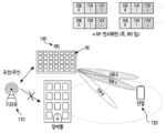
- FIG. 1 illustrates an example of a wireless communication environment including a reconfigurable intelligent surface (RIS) in a wireless communication system, according to various embodiments of the present disclosure.
- RIS reconfigurable intelligent surface
- FIG. 2 illustrates the functional configuration of a base station in a wireless communication system, according to various embodiments of the present disclosure.
- Figure 3 shows the functional configuration of a terminal in a wireless communication system according to various embodiments of the present disclosure.
- FIG. 4 illustrates the functional configuration of a RIS in a wireless communication system, according to various embodiments of the present disclosure.
- Figure 5 shows an example of a radio resource area in a wireless communication system, according to embodiments of the present disclosure.
- FIG. 6 illustrates a time-domain mapping structure and beam sweeping operation of a synchronization signal in a new radio (NR) system according to various embodiments of the present disclosure.
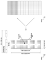
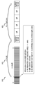
- FIG. 7 illustrates an example of a slot structure included in a signal related to a RIS pattern, according to various embodiments of the present disclosure.
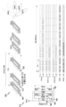
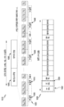
- FIG. 8 shows another example of a slot structure included in a signal related to a RIS pattern, according to various embodiments of the present disclosure.
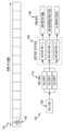
- Figure 9 shows an example of a resource structure for configuring a signal regarding a RIS pattern, according to various embodiments of the present disclosure.
- FIG. 10 shows the structures of a signal and a data signal related to a RIS pattern, according to various embodiments of the present disclosure.
- FIG. 11 illustrates a signal flow for performing beam sweeping using a RIS pattern according to various embodiments of the present disclosure.
- FIG. 12 illustrates a flow of operations for a base station to perform beam sweeping using a RIS pattern, according to various embodiments of the present disclosure.
- FIG. 13 illustrates a flow of operations for a terminal to perform beam sweeping using a RIS pattern, according to various embodiments of the present disclosure.
- a method performed by a base station includes generating a synchronization signal transmitted through at least one symbol and at least one slot including the at least one symbol.
- RIS reconfigurable intelligent surface
- a method performed by a terminal includes a synchronization signal transmitted from a base station through at least one symbol and the at least one symbol including the at least one symbol.
- Receiving a slot, the at least one symbol is used to determine an operation to be performed by the terminal during a predetermined time interval including the at least one slot, and, from the base station, one or more symbols formed according to a RIS pattern
- Receiving at least one slot containing the synchronization signal through a beam performing measurement for each beam based on one or more beams formed according to the RIS pattern, and transmitting the measurement result for each beam to the base station. It may include receiving a data signal from the base station through the RIS to which the RIS pattern determined based on the measurement results for each beam is applied.
- a base station in a wireless communication system, includes at least one transceiver; and at least one processor functionally coupled to the at least one transceiver, wherein the at least one processor includes at least one synchronization signal transmitted through at least one symbol and the at least one symbol.
- Generate one slot transmit the at least one slot including the at least one symbol to a reconfigurable intelligent surface (RIS) and a terminal, and the at least one symbol includes the at least one slot.
- RIS reconfigurable intelligent surface
- a terminal in a wireless communication system, includes at least one transceiver; and at least one processor functionally coupled to the at least one transceiver, wherein the at least one processor controls a synchronization signal transmitted through at least one symbol from a base station and the at least one symbol.
- the at least one symbol is used to determine an operation to be performed by the terminal during a predetermined time interval containing the at least one slot, and from the base station, the RIS pattern Receive at least one slot containing the synchronization signal through one or more beams formed according to the RIS pattern, perform beam-by-beam measurement based on the one or more beams formed according to the RIS pattern, and send the beam-by-beam measurement to the base station. It may be configured to transmit the results and receive a data signal from the base station through the RIS to which the RIS pattern determined based on the measurement results for each beam is applied.
- Terms used in the following description to refer to the components of the device e.g., control unit, processor, reflection element (RE)
- terms to refer to the device e.g., reconfigurable intelligent surface (RIS)
- data e.g. signal, feedback, report, reporting, information, parameter, value, bit, codeword, etc.
- Terms to refer to the concept of wireless communication e.g., channel, artificial channel, reflection pattern, beam, etc.
- wireless communication e.g., channel, artificial channel, reflection pattern, beam, etc.
- the present disclosure describes various embodiments using terms used in some communication standards (eg, 3rd Generation Partnership Project (3GPP)), but this is only an example for explanation.
- 3GPP 3rd Generation Partnership Project
- Various embodiments of the present disclosure can be easily modified and applied to other communication systems.
- FIG. 1 illustrates an example of a wireless communication environment including a reconfigurable intelligent surface (RIS), according to various embodiments of the present disclosure.
- Figure 1 illustrates a base station 110, a terminal 120, and a reconfigurable intelligent surface (RIS) 130 as some of the nodes that use a wireless channel in a wireless communication system.
- Figure 1 shows only one base station, but other base stations identical or similar to the base station 110 may be further included.
- Figure 1 shows only one RIS, but other RISs identical or similar to the RIS 130 may be further included.
- the base station 110 is a network infrastructure that provides wireless access to the terminal 120.
- the base station 110 has coverage defined as a certain geographic area based on the distance over which signals can be transmitted.
- the base station 110 includes 'access point (AP)', 'eNodeB (eNB)', '5G node (5th generation node)', and '6G node (6th generation node).
- AP access point
- eNB eNodeB
- eNB '5G node
- 6G node 6th generation node
- TRP transmission/reception point
- the terminal 120 is a device used by a user and communicates with the base station 110 through a wireless channel. In some cases, at least one of the terminals 120 may be operated without user involvement. That is, at least one of the terminals 120 is a device that performs machine type communication (MTC) and may not be carried by the user.
- the terminal 120 is a terminal, as well as 'user equipment (UE)', 'mobile station', 'subscriber station', and 'customer premises equipment (CPE)'. , may be referred to as 'remote terminal', 'wireless terminal', 'electronic device', or 'user device' or other terms with equivalent technical meaning. there is.
- the base station 110 and the terminal 120 can transmit and receive wireless signals in the millimeter wave (mmWave) band (e.g., 28 GHz, 30 GHz, 38 GHz, 60 GHz, over 60 GHz, etc.).
- mmWave millimeter wave
- the base station 110 and the terminal 120 may perform beamforming.
- beamforming may include transmission beamforming and reception beamforming. That is, the base station 110 and the terminal 120 can provide directionality to a transmitted signal or a received signal.
- the signal transmitted from the base station 110 to the terminal 120 may be reflected by the RIS 130 and transmitted to the terminal 120.
- the base station 110 can control at least one RIS reflection pattern to provide directionality to a signal transmitted to the terminal 120.
- the beamforming or beam management procedure performed by the base station 110 and the terminal 120 is based on the RIS reflection pattern adjusted by the base station 110. It may include beamforming and beam management procedures performed between the terminal 120 and the terminal 120.
- the base station 110 and the terminal 120 use a beam search or beam management procedure. Serving beams (SSB 0, SSB 1...SSB N) can be selected.
- the serving beams (SSB 0, SSB 1...SSB N) are selected, subsequent communication is performed using a resource in a quasi co-located (QCL) relationship with the resource that transmitted the serving beams (SSB 0, SSB 1...SSB N). This can be done through resources.
- QCL quasi co-located
- the terminal 120 may indirectly receive a signal transmitted from the base station 110 by reflecting it through the RIS 130. That is, the terminal 120 can receive the reflected signal reflected by the RIS (130).
- the RIS 130 may refer to a device including a plurality of reflection elements (RE).
- the RIS 130 may include a plurality of REs and a RIS controller (RIS controller, RC).
- RIS 130 may be connected to the base station 110.
- the RIS 130 may be connected to the base station 110 via a wire.
- the RIS 130 may be connected to the base station 110 wirelessly.
- the base station 110 may be connected wired or wirelessly to the RIS controller (RC) included in the RIS 130, and may provide a control signal so that the RIS controller can control the RIS reflection pattern using RE. Can be transmitted.
- RC RIS controller
- Each RE of the RIS 130 can adjust the phase and amplitude of the signal to be reflected.
- the RIS 130 may adjust the phase and amplitude of the signal received from the base station 110 by a specific value based on each RE.
- the combination of the phase and amplitude of the signal to be adjusted to a specific value may be referred to as a reflection pattern. That is, the RIS 130 can adjust the phase and amplitude of the signal received from the base station 110 based on the reflection pattern.
- the RIS controller that receives the control signal from the base station can control the reflection pattern of the RIS.
- RIS 130 may be operated based on a plurality of reflection patterns. For example, a first reflection pattern among a plurality of reflection patterns may be applied to a plurality of REs included in the RIS 130.
- the RIS 130 to which the first reflection pattern is applied may reflect the signal received from the base station 110 as a signal having first reflection characteristics.
- reflecting a signal with reflection characteristics changes the characteristics of the received signal and reflects it as is, or generates and transmits a new signal based on the characteristics of the received signal and the reflection pattern to be adjusted (reflection phase and reflection amplitude). It can mean doing.
- a second reflection pattern different from the first reflection pattern among the plurality of reflection patterns when applied to the RIS 130, it may be applied to a plurality of REs included in the RIS 130. At this time, the RIS 130 may reflect a signal having characteristics different from the signal reflected by the first reflection pattern. That is, the RIS 130 to which the second reflection pattern is applied can reflect a signal having second reflection characteristics. According to one embodiment, a plurality of reflection patterns may be included in one RIS beam book.
- the RIS 130 uses a specific reflection pattern and the time for which the specific reflection pattern is maintained (hereinafter referred to as a reflection pattern period). (referred to as a pattern period) can be determined.
- the reflection pattern and reflection pattern period of the RIS (130) can be configured from the base station (110).
- the RIS 130 may receive configuration information from the base station 110 and determine a reflection pattern and reflection pattern period based on this. Additionally, the RIS 130 may determine the reflection pattern and reflection pattern period based on information on the wire (wired connection) connected from the base station 110.
- determining a reflection pattern may mean that one of the reflection patterns of a specific RIS beam book is selected and used to reflect a signal. Therefore, according to various embodiments of the present disclosure, a signal transmitted by the base station to the terminal or a signal received by the terminal from the base station described below may include a signal transmitted from the base station and transmitted to the terminal through a RIS reflection pattern. .
- the terminal 130 which cannot receive a signal directly from the base station 110 due to an obstacle, can maintain communication by receiving a signal reflected by the RIS 130. Additionally, the base station can determine the reflection pattern of the RIS that reflects the signal transmitted to the terminal. For efficient signal transmission and reception in consideration of beam direction or beamforming, the base station may perform beam sweeping using at least one RIS pattern. However, since the RIS pattern is used for beamforming of the base station, the beam sweeping operation using SSB between the existing base station and the terminal may generally be inefficient in terms of complexity, accuracy, or delay time. Therefore, according to various embodiments of the present disclosure, when performing beamforming using a RIS pattern, a method of transmitting and receiving a signal to optimize a beam sweeping operation may be discussed.
- FIG. 2 illustrates the functional configuration of a base station in a wireless communication system, according to various embodiments of the present disclosure.
- the configuration illustrated in FIG. 2 may be understood as the configuration of the base station 110.
- Terms such as '... unit' and '... unit' used hereinafter refer to a unit that processes at least one function or operation, which can be implemented through hardware, software, or a combination of hardware and software. there is.
- the base station 110 may include a wireless communication unit 210, a backhaul communication unit 220, a storage unit 230, and a control unit 240.
- the wireless communication unit 210 performs functions for transmitting and receiving signals through a wireless channel. For example, the wireless communication unit 210 performs a conversion function between a baseband signal and a bit string according to the physical layer standard of the system. For example, when transmitting data, the wireless communication unit 210 generates complex symbols by encoding and modulating the transmission bit string. Additionally, when receiving data, the wireless communication unit 210 restores the received bit stream by demodulating and decoding the baseband signal. Additionally, the wireless communication unit 210 upconverts the baseband signal into a radio frequency (RF) band signal and transmits it through an antenna, and downconverts the RF band signal received through the antenna into a baseband signal.
- RF radio frequency
- the wireless communication unit 210 may include a transmission filter, a reception filter, an amplifier, a mixer, an oscillator, a digital to analog convertor (DAC), an analog to digital convertor (ADC), etc. Additionally, the wireless communication unit 210 may include multiple transmission and reception paths. Furthermore, the wireless communication unit 210 may include at least one antenna array composed of a plurality of antenna elements. In terms of hardware, the wireless communication unit 210 may be composed of a digital unit and an analog unit, and the analog unit includes a number of sub-units depending on operating power, operating frequency, etc. It can be composed of:
- the wireless communication unit 210 can transmit and receive signals.
- the wireless communication unit 210 may include at least one transceiver.
- the wireless communication unit 210 may transmit a synchronization signal, reference signal, system information, message, control information, or data. Additionally, the wireless communication unit 210 may perform beamforming.
- the wireless communication unit 210 transmits and receives signals as described above. Accordingly, all or part of the wireless communication unit 210 may be referred to as a ‘transmission unit’, a ‘reception unit’, or a ‘transmission/reception unit’. Additionally, in the following description, transmission and reception performed through a wireless channel are used to mean that the processing as described above is performed by the wireless communication unit 210.
- the backhaul communication unit 220 provides an interface for communicating with other nodes in the network. That is, the backhaul communication unit 220 converts a bit string transmitted from the base station 110 to another node, for example, another access node, another base station, upper node, core network, etc., into a physical signal, and Converts physical signals into bit strings.
- another node for example, another access node, another base station, upper node, core network, etc.
- the storage unit 230 stores data such as basic programs, application programs, and setting information for operation of the base station 110.
- the storage unit 230 may include memory.
- the storage unit 230 may be comprised of volatile memory, non-volatile memory, or a combination of volatile memory and non-volatile memory. And, the storage unit 230 provides stored data according to the request of the control unit 240.
- the control unit 240 controls the overall operations of the base station 110. For example, the control unit 240 transmits and receives signals through the wireless communication unit 210 or the backhaul communication unit 220. Additionally, the control unit 240 records and reads data from the storage unit 230. Additionally, the control unit 240 can perform protocol stack functions required by communication standards. For this purpose, the control unit 240 may include at least one processor.
- the configuration of the base station 110 shown in FIG. 2 is only an example of a base station, and examples of base stations that perform various embodiments of the present disclosure are not limited to the configuration shown in FIG. 2. That is, some configurations may be added, deleted, or changed according to various embodiments.
- the base station is described as one entity, but the present disclosure is not limited to this.
- the base station may be implemented to form an access network with an integrated deployment as well as a distributed deployment.
- the base station is divided into a central unit (CU) and a digital unit (DU), with the CU performing upper layer functions (e.g., packet data convergence protocol (PDCP, RRC)) and the DU performing lower layer functions. It can be implemented to perform (lower layers) (e.g. MAC (medium access control), PHY (physical)).
- the base station may further include a radio unit (RU) that processes radio frequency (RF) signals.
- the base station's DU can form beam coverage on the wireless channel.
- Figure 3 shows the functional configuration of a terminal in a wireless communication system according to various embodiments of the present disclosure.
- the configuration illustrated in FIG. 3 can be understood as the configuration of the terminal 120.
- Terms such as '... unit' and '... unit' used hereinafter refer to a unit that processes at least one function or operation, which can be implemented through hardware, software, or a combination of hardware and software. there is.
- the terminal 120 may include a communication unit 310, a storage unit 320, and a control unit 330.
- the communication unit 310 performs functions for transmitting and receiving signals through a wireless channel. For example, the communication unit 310 performs a conversion function between a baseband signal and a bit string according to the physical layer standard of the system. For example, when transmitting data, the communication unit 310 generates complex symbols by encoding and modulating the transmission bit string. Additionally, when receiving data, the communication unit 310 restores the received bit stream by demodulating and decoding the baseband signal. Additionally, the communication unit 310 upconverts the baseband signal into an RF band signal and transmits it through an antenna, and downconverts the RF band signal received through the antenna into a baseband signal. For example, the communication unit 310 may include a transmission filter, reception filter, amplifier, mixer, oscillator, DAC, ADC, etc.
- the communication unit 310 may include multiple transmission and reception paths. Furthermore, the communication unit 310 may include an antenna unit. The communication unit 310 may include at least one antenna array comprised of multiple antenna elements. In terms of hardware, the communication unit 310 may be composed of digital circuits and analog circuits (eg, radio frequency integrated circuit (RFIC)). Here, the digital circuit and analog circuit can be implemented in one package. Additionally, the communication unit 310 may include multiple RF chains. The communication unit 310 may perform beamforming. The communication unit 310 may apply a beamforming weight to the signal to be transmitted and received in order to give directionality according to the settings of the control unit 330. According to one embodiment, the communication unit 310 may include a radio frequency (RF) block (or RF unit).
- RF radio frequency
- the RF block may include a first RF circuitry related to an antenna and a second RF circuitry related to baseband processing.
- the first RF circuit may be referred to as RF-A (antenna).
- the second RF circuit may be referred to as RF-B (baseband).
- the communication unit 310 can transmit and receive signals.
- the communication unit 310 may include at least one transceiver.
- the communication unit 310 can receive a downlink signal.
- Downlink signals include synchronization signal (SS), reference signal (RS) (e.g., cell-specific reference signal (CRS), demodulation (DM)-RS), system information (e.g., MIB, SIB, It may include remaining system information (RMSI), other system information (OSI), a configuration message, control information, or downlink data.
- RS reference signal
- DM demodulation
- MIB cell-specific reference signal
- SIB system information
- RMSI remaining system information
- OSI system information
- the communication unit 310 can transmit an uplink signal.
- Uplink signals include random access-related signals (e.g., random access preamble (RAP) (or Msg1 (message 1)), Msg3 (message 3)), reference signals (e.g., sounding reference signal (SRS), DM) -RS), or power headroom report (PHR), etc.
- RAP random access preamble
- Msg1 messagessage 1
- Msg3 messagessage 3
- reference signals e.g., sounding reference signal (SRS), DM) -RS
- PHR power headroom report
- the communication unit 310 may include different communication modules to process signals in different frequency bands. Furthermore, the communication unit 310 may include multiple communication modules to support multiple different wireless access technologies. For example, different wireless access technologies include Bluetooth low energy (BLE), wireless fidelity (Wi-Fi), WiFi gigabyte (WiGig), and cellular networks (e.g. long term evolution (LTE), new wireless access (NR)).
- different frequency bands may include super high frequency (SHF) (e.g., 2.5GHz, 5Ghz) bands and millimeter wave (e.g., 38GHz, 60GHz, etc.) bands.
- SHF super high frequency
- the communication unit 310 may provide the same wireless access on different frequency bands (e.g., unlicensed band for licensed assisted access (LAA), citizens broadband radio service (CBRS) (e.g., 3.5 GHz)). You can also use technology.
- LAA licensed assisted access
- CBRS citizens broadband radio service
- the communication unit 310 transmits and receives signals as described above. Accordingly, all or part of the communication unit 310 may be referred to as a ‘transmission unit’, a ‘reception unit’, or a ‘transmission/reception unit’. Additionally, in the following description, transmission and reception performed through a wireless channel are used to mean that the processing as described above is performed by the communication unit 310.
- the storage unit 320 stores data such as basic programs, application programs, and setting information for operation of the terminal 120.
- the storage unit 320 may be comprised of volatile memory, non-volatile memory, or a combination of volatile memory and non-volatile memory. And, the storage unit 320 provides stored data according to the request of the control unit 330.
- the control unit 330 controls the overall operations of the terminal 120. For example, the control unit 330 transmits and receives signals through the communication unit 310. Additionally, the control unit 330 records and reads data from the storage unit 320. Additionally, the control unit 330 can perform protocol stack functions required by communication standards. For this purpose, the control unit 330 may include at least one processor. The control unit 330 may include at least one processor or microprocessor, or may be part of a processor. Additionally, a portion of the communication unit 310 and the control unit 330 may be referred to as CP. The control unit 330 may include various modules for performing communication. According to various embodiments, the control unit 330 may control the terminal to perform operations according to various embodiments. The configuration of the terminal 120 shown in FIG. 3 is only an example of a terminal, and examples of terminals that perform various embodiments of the present disclosure are not limited to the configuration shown in FIG. 3. That is, some configurations may be added, deleted, or changed according to various embodiments.
- FIG. 4 illustrates the functional configuration of a reconfigurable intelligent surface (RIS) in a wireless communication system, according to various embodiments of the present disclosure.
- FIG. 4 may be understood as the functional configuration of a RIS controller included in RIS.
- the configuration illustrated in FIG. 4 may be understood as the configuration of the RIS 130.
- Terms such as '... unit' and '... unit' used hereinafter refer to a unit that processes at least one function or operation, which can be implemented through hardware, software, or a combination of hardware and software. there is.
- the RIS 130 may include a wireless communication unit 410, a backhaul communication unit 420, a storage unit 430, and a control unit 440.
- the wireless communication unit 410 performs functions for transmitting and receiving signals through a wireless channel. For example, the wireless communication unit 410 performs a conversion function between a baseband signal and a bit string according to the physical layer standard of the system. For example, when transmitting data, the wireless communication unit 410 generates complex symbols by encoding and modulating the transmission bit string. Additionally, when receiving data, the wireless communication unit 410 restores the received bit stream by demodulating and decoding the baseband signal. Additionally, the wireless communication unit 410 upconverts the baseband signal into a radio frequency (RF) band signal and transmits it through an antenna, and downconverts the RF band signal received through the antenna into a baseband signal.
- RF radio frequency
- the wireless communication unit 410 of the RIS 130 may receive a signal from the base station 110, reflect the received signal, and transmit it to the terminal 120. Additionally, the wireless communication unit 410 of the RIS 130 may receive a signal from the terminal 120, reflect the received signal, and transmit it to the base station 110. At this time, the RIS 130 may reflect the received signal as is or transmit a signal generated based on information of the received signal through the wireless communication unit 410. According to one embodiment, the RIS 130 may adjust the RIS reflection pattern based on the control signal received from the base station 110 and may reflect the received signal based on the adjusted RIS reflection pattern.
- the wireless communication unit 410 may include a transmission filter, a reception filter, an amplifier, a mixer, an oscillator, a digital to analog convertor (DAC), an analog to digital convertor (ADC), etc. Additionally, the wireless communication unit 410 may include multiple transmission and reception paths. Furthermore, the wireless communication unit 410 may include at least one antenna array composed of a plurality of antenna elements. In terms of hardware, the wireless communication unit 410 may be composed of a digital unit and an analog unit, and the analog unit includes a number of sub-units depending on operating power, operating frequency, etc. It can be composed of:
- the wireless communication unit 410 may include a plurality of reflection elements (RE). Based on the plurality of REs, the wireless communication unit 410 may reflect signals. In the case of reflection, the amplitude and phase of the received signal can be adjusted to specific values. The combination of amplitude and phase of a signal to be adjusted to a specific value may be referred to as a reflection pattern. According to one embodiment, signal reflection based on various reflection patterns may include substantially the same or similar functions as beamforming of the base station 110.
- RE reflection elements
- the wireless communication unit 410 can transmit and receive signals.
- the wireless communication unit 410 may include at least one transceiver.
- the wireless communication unit 410 may transmit a synchronization signal, reference signal, system information, message, control information, or data. Additionally, the wireless communication unit 410 may perform beamforming.
- the wireless communication unit 410 transmits and receives signals as described above. Accordingly, all or part of the wireless communication unit 410 may be referred to as a ‘transmission unit’, a ‘reception unit’, or a ‘transmission/reception unit’. Additionally, in the following description, transmission and reception performed through a wireless channel are used to mean that the processing as described above is performed by the wireless communication unit 410.
- the backhaul communication unit 420 provides an interface for communicating with other nodes in the network. That is, the backhaul communication unit 420 converts a bit string transmitted from the RIS 130 to another node, for example, another access node, base station, upper node, core network, etc., into a physical signal, and converts the bit string transmitted from the RIS 130 to a physical signal received from the other node. Convert the signal to a bit string.
- the RIS 130 may receive setting information about the reflection pattern and reflection pattern period from the base station 110 through the backhaul communication unit 420.
- the storage unit 430 stores data such as basic programs, application programs, and setting information for operation of the RIS (130).
- the storage unit 430 may include memory.
- the storage unit 430 may be comprised of volatile memory, non-volatile memory, or a combination of volatile memory and non-volatile memory.
- the storage unit 430 provides stored data according to the request of the control unit 440.
- the storage unit 430 may store information (i.e., RIS beambook) on a plurality of reflection patterns applied to the RIS 130 in advance.
- the control unit 440 controls the overall operations of the RIS (130). For example, the control unit 440 transmits and receives signals through the wireless communication unit 410 or the backhaul communication unit 420. Additionally, the control unit 440 records and reads data from the storage unit 430. Additionally, the control unit 440 can perform protocol stack functions required by communication standards. For this purpose, the control unit 440 may include at least one processor.
- the configuration of the RIS 130 shown in FIG. 4 is only an example of a RIS, and examples of base stations that perform various embodiments of the present disclosure are not limited to the configuration shown in FIG. 4. That is, some configurations may be added, deleted, or changed according to various embodiments.
- Figure 5 shows an example of a radio resource area in a wireless communication system, according to embodiments of the present disclosure.
- the radio resource area may include a structure of a time-frequency area.
- the wireless communication system may include a NR communication system.
- the horizontal axis represents the time domain and the vertical axis represents the frequency domain.
- the length of the wireless frame 504 is 10 ms.
- the radio frame 504 may be a time domain section consisting of 10 subframes.
- the length of the subframe 503 is 1 ms.
- the unit in the time domain may be orthogonal frequency division multiplexing (OFDM) and/or discrete fourier transform (DFT)-spread-OFDM (DFT-s-OFDM) symbols, and may be Nsymb OFDM and/or DFT-s-OFDM symbols.
- Symbols 501 may be gathered to form one slot 502.
- the OFDM symbol may include a symbol for transmitting and receiving signals using the OFDM multiplexing method
- the DFT-s-OFDM symbol may include DFT-s-OFDM or SC-FDMA ( It may include symbols for transmitting and receiving signals using a single carrier frequency division multiple access (multiple access) multiplexing method.
- the minimum transmission unit in the frequency domain is a subcarrier, and the carrier bandwidth constituting the resource grid may be composed of a total of NscBW subcarriers 505.
- embodiments related to downlink signal transmission and reception are described for convenience of explanation, but this is also applicable to embodiments related to uplink signal transmission and reception.
- the number of slots 502 constituting one subframe 503 and the length of the slots 502 may vary depending on the subcarrier spacing.
- This subcarrier spacing may be referred to as numerology ( ⁇ ).
- ⁇ numerology
- the subcarrier spacing, the number of slots included in the subframe, the length of the slot, and the length of the subframe can be variably configured.
- the subcarrier spacing (SCS) when the subcarrier spacing (SCS) is 15 kHz, one slot 502 constitutes one subframe 503, and the slot 502 and the subframe 503
- the length of may be 1 ms each.
- the subcarrier spacing is 30 kHz
- two slots may constitute one subframe 503. At this time, the length of the slot is 0.5ms and the length of the subframe is 1ms.
- the subcarrier spacing, the number of slots included in the subframe, the length of the slot, and the length of the subframe may be applied variably depending on the communication system.
- the subcarrier interval is 15 kHz, and two slots constitute one subframe.
- the length of the slot may be 0.5 ms and the length of the subframe may be 1 ms.
- the subcarrier spacing ( ⁇ ) may be one of 15kHz, 30kHz, 60kHz, 120kHz, and 240kHz, and the number of slots included in one subframe depending on the subcarrier spacing ( ⁇ ) can be 1, 2, 4, 8, 16.
- the basic unit of resources may be a resource element (RE) 506, and the resource element 506 may be expressed as an OFDM symbol index and a subcarrier index.
- a resource block may include a plurality of resource elements.
- the frequency domain may include common resource blocks (CRBs).
- a physical resource block (PRB) may be defined in the bandwidth part (BWP) in the frequency domain. CRB and PRB numbers may be determined differently depending on the subcarrier spacing.
- an RB can be defined as Nsymb consecutive OFDM symbols in the time domain and N SCRB consecutive subcarriers in the frequency domain.
- scheduling information for downlink data or uplink data may be transmitted from the base station 110 to the terminal 120 through downlink control information (DCI).
- DCI may be defined according to various formats, and each format determines whether the DCI includes scheduling information (e.g., UL grant) for uplink data or scheduling information for downlink data. It may indicate whether it includes (DL resource allocation), whether it is a compact DCI with a small size of control information, whether it is a fall-back DCI, whether spatial multiplexing using multiple antennas is applied, and/or whether it is a DCI for power control.
- NR DCI format 1_0 or NR DCI format 1_1 may include scheduling for downlink data.
- NR DCI format 0_0 or NR DCI format 0_1 may include scheduling for uplink data.
- Figure 5 shows an example of a downlink and uplink slot structure in a wireless communication system.
- Figure 5 shows the structure of the resource grid of the 3GPP NR system.
- a slot may include a plurality of orthogonal frequency division multiplexing (OFDM) symbols in the time domain and a plurality of resource blocks (RBs) in the frequency domain.
- OFDM orthogonal frequency division multiplexing
- RBs resource blocks
- a signal may consist of part or all of a resource grid.
- the number of OFDM symbols included in one slot may vary depending on the length of the CP (cyclic prefix).
- FIG. 5 for convenience of explanation, the case where one slot is composed of 14 OFDM symbols is illustrated, but in the case of the signal referred to in this disclosure, the configuration of the symbols is not specified.
- the modulation method of the generated signal is not limited to a specific value of QAM (Quadrature Amplitude Modulation), and can follow the modulation method of various communication standards such as BPSK (Binary phase-shift keying) and QPSK (Quadrature Phase Shift Keying). there is.
- QAM Quadrature Amplitude Modulation
- BPSK Binary phase-shift keying
- QPSK Quadrature Phase Shift Keying
- an operation for performing beam sweeping using a RIS pattern is described based on an LTE communication system or an NR communication system, but the content of the present disclosure is not limited thereto, but is based on downlink or uplink It can be applied in various wireless communication systems for transmitting control information.
- the contents of this disclosure can be applied to unlicensed bands as well as licensed bands, as needed.
- higher layer signaling or higher signal is transmitted from the base station 110 to the terminal 120 using a physical layer downlink data channel, or from the terminal 120 to the physical layer uplink data channel. It may be a signal transmission method transmitted to the base station 110 using . According to one embodiment, the signal transmitted from the base station to the terminal may be transmitted through the RIS reflection plane. According to one embodiment, the upper layer signaling is radio resource control (RRC) signaling, or signaling according to the F1 interface between a centralized unit (CU) and a distributed unit (DU), or a media access control (MAC) control element. It may include at least one of the signal transmission methods transmitted through a control element (MAC CE). Additionally, according to one embodiment, higher layer signaling or higher signal may include system information commonly transmitted to a plurality of terminals 120, for example, a system information block (SIB).
- SIB system information block
- a synchronization signal block (or referred to as SS Block, SS/PBCH block, etc.) may be transmitted for initial access, and the synchronization signal block may be transmitted as a primary synchronization (PSS) signal), SSS (secondary synchronization, signal), and PBCH (physical broadcast channel).
- PSS primary synchronization
- SSS secondary synchronization, signal
- PBCH physical broadcast channel
- SSB may include information about the beam used by the base station to transmit a signal, and the SSB index or SSB described below may mean at least one beam.
- the terminal obtains downlink time and frequency domain synchronization from a synchronization signal through a cell search procedure and uses a cell ID. can be obtained.
- Synchronization signals may include PSS and SSS.
- the terminal can receive a PBCH including a master information block (MIB) from the base station and obtain system information and basic parameter values related to transmission and reception, such as system bandwidth or related control information.
- the terminal may obtain a system information block (SIB) by performing decoding on a physical downlink control channel (PDCCH) and a physical downlink shared channel (PDSCH) based on the received PBCH.
- SIB system information block
- the terminal exchanges its identity with the base station through a random access step and can initially access the network through steps such as registration and authentication.
- one slot may include 14 symbols.
- uplink-downlink configuration of symbols and/or slots in a 5G communication system can be set in three steps. there is.
- uplink-downlink of a symbol and/or slot can be set semi-statically through cell-specific configuration information through system information in a symbol unit. More specifically, cell-specific uplink-downlink configuration information through system information may include uplink-downlink pattern information and standard subcarrier information.
- Uplink-downlink pattern information includes the pattern period, the number of consecutive downlink slots from the starting point of each pattern, the number of symbols in the next slot, the number of consecutive uplink slots from the end of the pattern, and the symbol of the next slot. The number can be indicated. Slots and symbols that are not indicated as uplink or downlink may be determined as flexible slots/symbols.
- a flexible slot or a slot containing flexible symbols is configured to determine the number of consecutive downlink symbols and slots from the start symbol of each slot. It can be indicated as the number of consecutive uplink symbols from the end of , or it can be indicated as the entire downlink of the slot or the uplink of the entire slot.
- symbols indicated as flexible symbols in each slot may indicate whether each is a downlink symbol, an uplink symbol, or a flexible symbol through a slot format indicator (SFI) included in the downlink control channel.
- SFI slot format indicator
- the slot format indicator can select one index from a table in which the uplink-downlink configuration of 14 symbols in one slot is preset (e.g., 3GPP TS 38.213 Table 11.1.1-1).
- FIG. 6 illustrates a time-domain mapping structure and beam sweeping operation of a synchronization signal in a new radio (NR) system according to various embodiments of the present disclosure.
- - PSS primary synchronization signal 602: A signal that serves as a standard for DL time/frequency synchronization and may provide some cell ID information.
- - SSS secondary synchronization signal 604: It serves as a standard for DL time/frequency synchronization and can provide the cell ID and some remaining information. Additionally, it can serve as a reference signal for demodulation of PBCH.
- MIB master information block
- Essential system information includes search space-related control information indicating radio resource mapping information of the control channel, scheduling control information for a separate data channel transmitting system information, and SFN (System Frame), which is a frame unit index that serves as a timing standard. Number), etc. may be included.
- the SS/PBCH block may consist of N OFDM symbols and may include a combination of PSS, SSS, PBCH, etc. .
- the SS/PBCH block includes PSS occupying 127 subcarriers in the first OFDM symbol, SSS occupying 127 subcarriers in the third OFDM symbol, and
- the fourth OFDM symbol may include a PBCH occupying 240 subcarriers each and 48 subcarriers on each side of the SSS.
- an SSB burst set (combined with SS burst set) including at least one SS/PBCH block is shown (620).
- the base station can transmit up to L SS/PBCH blocks, and L SS/PBCH blocks can be mapped within a half frame (5ms).
- L SS/PBCH blocks may be periodically repeated in units of P, which is a predetermined period (eg, 20 ms).
- the number (L) of SS/PBCH blocks included in one SS/PBCH burst set may vary depending on the numerology.
- L per half frame can be 4 or 8, and in a higher frequency band (e.g., FR 2), if the subcarrier spacing is 240 kHz , L per half frame may be 64.
- the period P can be informed to the terminal by the base station through signaling. If there is no separate signaling for period P, the terminal can apply a pre-arranged default value.
- FIG. 5 shows an example in which beam sweeping is applied on a SS/PBCH block basis over time (620).
- the terminal uses a beam radiated in the SB #1 direction to SB #L by beamforming applied to SS/PBCH block #1 (605) to block #L (625).
- SS/PBCH blocks can be received.
- the terminal can obtain the optimal synchronization signal through a beam radiating from the base station in the direction where the terminal is located.
- a beam may mean an SS/PBCH block, and beam sweeping may include transmitting different SS/PBCH blocks in a time division multiplexed environment.
- the terminal may receive an SS/PBCH block to determine whether the radio link quality of the current cell is maintained above a certain level. Additionally, in the handover procedure in which the terminal moves access from the current cell to an adjacent cell, the terminal determines the radio link quality of the adjacent cell and uses the SS/PBCH block of the adjacent cell to obtain time/frequency synchronization of the adjacent cell. You can receive it.
- the base station can control the RIS reflection pattern using L1 signaling or radio resource control (RRC) signaling.
- RRC radio resource control
- the base station may perform RIS beam sweeping by controlling the RIS reflection pattern.
- the base station knows in advance the specific reflection pattern information to be applied at each point in time, and can transmit one or more SSBs each mapped to at least one RIS beam corresponding to the specific reflection pattern to the terminal.
- the terminal can detect the best SSB ID by calculating the signal strength for each SSB based on the received SSB, and report the detection result to the base station.
- the base station can perform efficient communication using an optimal beam by transmitting a data signal by applying a RIS pattern corresponding to the SSB based on the detection result.
- a base station may further transmit a signal related to a RIS pattern in addition to a signal including SSB for synchronization and beam sweeping of the 5G system.
- a signal related to the RIS pattern described in the present disclosure includes a synchronization signal transmitted through at least one symbol generated by a base station and at least one slot including at least one symbol. May contain signals.
- a signal related to a RIS pattern may have a structure with reduced complexity in terms of time resources and may have the structural characteristic of being transmitted for every slot.
- the base station transmits and transmits relatively low-capacity data at low speeds and applies signals related to the RIS pattern to communication systems such as mMTC (massive machine type communication) or passive IoT (passive internet of things) that require low-power and low-complexity performance. In this case, more efficient signal transmission and reception can be performed.
- the base station when transmitting a signal related to a RIS pattern, can transmit a synchronization signal at every slot, making it suitable for an environment that requires time synchronization between different communication nodes, such as an unlicensed band communication system.
- the configuration included in the signal related to the RIS pattern and the operations of the base station, RIS, and terminal that perform beam sweeping based on this are described in detail.
- FIG. 7 illustrates an example of a slot structure included in a signal related to a RIS pattern, according to various embodiments of the present disclosure.
- FIG. 7 shows an example of a slot structure included in a signal related to a RIS pattern transmitted by a base station.
- the slot structure disclosed in FIG. 7 is shown based on the time axis including slot and symbol units, but is not limited thereto, and includes time division duplexing (TDD), frequency division duplexing (FDD), and TDM. This does not exclude application to various communication systems including time division multiplexing (time division multiplexing), frequency division multiplexing (FDM), and half duplex (HD).
- TDD time division duplexing
- FDD frequency division duplexing
- HD half duplex
- a signal related to a RIS pattern may include at least one slot including a plurality of (eg, 14) symbols (710).
- At least one slot may include a resource element (RE) 702 to which a specific sequence is mapped.
- a specific sequence may be mapped to a certain number of frequency axis resource elements corresponding to one symbol included in at least one slot.
- the PSS sequence is mapped to 127 resource elements, and the PSS sequence can be applied based on the basic 127-m-sequence.
- the terminal can detect the synchronization of the PSS cycle by searching the PSS sequence based on the m-sequence. That is, the base station can perform synchronization with the terminal based on the PSS.
- one or more symbols 702 included in at least one slot may be mapped to an m-sequence.
- the symbol 702 mapped to the m-sequence may include information for time synchronization of the base station and the terminal and an indicator indicating the role of at least one slot.
- an indicator indicating the role of a slot may include at least one type of sequence among ⁇ X 0 ⁇ , ⁇ X 1 ⁇ , or ⁇ X 2 ⁇ .
- sequence 7 is explained focusing on a symbol mapped to an m-sequence, but is not limited thereto, and is a constant amplitude zero auto-correlation (CAZAC) function that performs substantially the same or similar function.
- CAZAC constant amplitude zero auto-correlation
- sequence, Zadoff-Chu sequence, and Gold sequence can include symbols mapped to sequences with excellent autocorrelation characteristics.
- At least one slot may include a symbol 702 mapped to an m-sequence (eg, ⁇ X m ⁇ ).
- the symbol 702 mapped to the m-sequence includes information about time synchronization, and the terminal that has received at least one slot from the base station can obtain time synchronization with the base station based on the symbol 702. .
- the symbol 702 may include an indicator indicating the role of at least one slot, and the terminal that has received at least one slot from the base station may determine the role of the at least one slot received based on the symbol 702. can be identified.
- At least one slot may serve to instruct the terminal to detect the SSB ID.
- symbol 702 may include information indicating that at least one slot detects the SSB ID.
- a terminal that has received at least one slot containing a symbol mapped to the ⁇ X 0 ⁇ sequence can perform an operation to detect the SSB ID.
- the operation of the terminal detecting the SSB ID may include detecting information related to the SSB ID included in at least one slot.
- the SSB ID detected by the terminal may include at least one of an SS/PBCH block index, information about the RIS pattern, or a RIS pattern index.
- the terminal when at least one slot includes a symbol mapped to the ⁇ X 0 ⁇ sequence, transmits a signal including the at least one slot using the remaining resources of the at least one slot. It is possible to identify the index of the received beam (e.g., identify the RIS pattern from which the signal including at least one slot is reflected), and measure the beam based on the received signal (e.g., L1-RSRP (reference signals received power measurement) can be performed.
- L1-RSRP reference signals received power measurement
- At least one slot may serve to indicate that the at least one slot is a slot for RIS beam switching.
- the symbol 702 may include information indicating that at least one slot is a slot for RIS beam switching. For example, a terminal that has received at least one slot containing a symbol mapped to the ⁇ Therefore, you can proceed in idle mode.
- At least one slot may serve to indicate that the at least one slot is a slot for data transmission.
- the symbol 702 may include information indicating that at least one slot is a slot for data transmission. For example, a terminal that has received at least one slot including a symbol mapped to the ⁇ X 2 ⁇ sequence can identify that the at least one slot is a slot for data transmission.
- the terminal may perform data decoding using the remaining resources of the at least one slot.
- the remaining resources of at least one slot in which the terminal performs data decoding may include information such as data information or a demodulate reference signal (DMRS) for decoding.
- DMRS demodulate reference signal
- the base station may transmit at least one slot containing a symbol mapped to the ⁇ X 1 ⁇ sequence, and the RIS switched accordingly Based on the pattern, signals containing symbols and data symbols mapped to the ⁇ X 2 ⁇ sequence can be transmitted.
- the signal 705 that the terminal receives from the base station may include a signal mapped to a different sequence or a synchronization signal to which a different cyclic shift (CS) is applied.
- CS cyclic shift
- the signal 705 that the terminal receives from the base station may include a signal mapped to a different sequence or a synchronization signal to which a different cyclic shift (CS) is applied.
- CS cyclic shift
- the terminal may receive a signal from a base station through RIS (705), and the received signal may include a reference sequence (715).
- the reference sequence may include at least one of a ⁇ X 0 ⁇ correlator, a ⁇ X 1 ⁇ correlator, or a ⁇ X 2 ⁇ correlator.
- the terminal can compare the correlation coefficient of the reference sequence (725) and identify the maximum correlation value to identify time synchronization with the base station and the role of the signal.
- a structure in which the symbol of at least one slot included in a signal transmitted from the base station to the terminal is mapped to an m-sequence is shown, but this is only an example, and at least one slot is autocorrelated It may include symbols that are mapped to any sequence with excellent characteristics, and of course, the role of the slot that each sequence can indicate or the operation of the terminal may vary accordingly.
- the structure of at least one slot shown in FIG. 7 can include various information so that the terminal can obtain time synchronization and identify the role of at least one slot, and such information
- the mapping method or specific slot structure can be implemented in various ways as long as it does not exceed the scope of the function.
- FIG. 8 shows another example of a slot structure included in a signal related to a RIS pattern, according to various embodiments of the present disclosure.
- FIG. 8 shows an example of a slot structure included in a signal related to a RIS pattern transmitted by a base station, in addition to the slot structure disclosed in FIG. 7.
- the slot structure disclosed in FIG. 8 is shown based on the time axis including slot and symbol units, but is not limited thereto and includes time division duplexing (TDD), frequency division duplexing (FDD), and TDM This does not exclude application to various communication systems including time division multiplexing (time division multiplexing), frequency division multiplexing (FDM), half duplex (HD), etc.
- TDD time division duplexing
- FDD frequency division duplexing
- HD half duplex
- Figure 8 shows a symbol mapped to the m-sequence disclosed in Figure 7 (although a slot structure including 802 is shown, the present invention is not limited thereto, and at least one slot 810 may include only the symbol 804 excluding the symbol 802.
- a signal related to a RIS pattern may include at least one slot including a plurality of (eg, 14) symbols (810).
- At least one slot may include resource elements (REs) 802 and 804 to which a specific sequence is mapped.
- a specific sequence may be mapped to a certain number of frequency axis resource elements corresponding to one symbol included in at least one slot.
- the PSS sequence of the LTE system can be applied based on the basic Zadoff-chu sequence.
- one or more symbols 804 included in at least one slot may be mapped to a Zadoff-chu sequence.
- the symbol 804 mapped to the Zadoff-chu sequence may include information on at least one beam transmitted by the base station through RIS.
- at least one beam is transmitted by at least one RIS pattern and may correspond to at least one RIS pattern.
- information on at least one beam may include an SSB ID (or index) or a beam ID (or index).
- the information of at least one beam may include information in which the SSB ID is encoded with a cyclic shift (CS).
- CS cyclic shift
- CAZAC constant amplitude CAZAC
- At least one slot may include a symbol 804 mapped to a Zadoff-chu sequence.
- the symbol 802 mapped to the Zadoff-chu sequence includes information about the beam index (e.g., SSB index or RIS pattern index), and the terminal that has received at least one slot from the base station uses the symbol 804. Based on , the beam index (hereinafter, including the SSB index or RIS pattern index) of the signal through which at least one received slot is transmitted can be identified.
- the terminal when the symbol 804 is mapped to the zadoff-chu sequence, the terminal can identify the encoded beam index using the CS included in the symbol 804. The terminal can perform beam measurement on the signal based on the identified beam index and report the beam measurement results to the base station.
- the terminal may identify the beam index of a signal including at least one slot based on one symbol 804 included in the received at least one slot.
- the terminal can perform a correlation operation between the symbol 804 of at least one slot 810 included in the received signal 805 and the basic sequence, and as a result of the operation, the terminal includes at least one slot. It may be determined that the beam index of the signal is 5.
- the terminal may receive a signal from a base station through RIS (805), and the received signal may include one symbol (802) mapped to an m-sequence correlator within at least one slot. (815).
- the terminal can compare the correlation coefficients of the reference sequence and identify the maximum correlation value to identify time synchronization with the base station and the role of the signal (825).
- the signal received by the terminal may include one symbol 804 mapped to the zadoff-chu sequence correlator within at least one slot (835).
- the terminal can identify the peak value by detecting one symbol 804 mapped to the zadoff-chu sequence and identify the corresponding beam index based on the identified peak value.
- Figure 8 shows that at least one slot received by the terminal includes a symbol 802 and a symbol 804, and the terminal initiates an operation of decoding all of them, but is not limited to this and at least one slot
- Each symbol may exist independently in a slot, and the terminal may only perform a separate operation corresponding to each symbol.
- the terminal can identify the role of at least one slot of the received signal and the beam index corresponding to the at least one slot, and confirm the operation of the base station based on the identification result (855). For example, the terminal can identify whether the base station is performing RIS switching or transmitting data based on the identification result. Additionally, the terminal may determine the operation of the terminal based on the identification result (865). For example, the terminal may perform at least one of detecting a beam index, entering an idle mode, or decoding data based on information indicated by at least one slot of the received signal.
- a structure in which the symbol of at least one slot included in the signal transmitted from the base station to the terminal is mapped to the zadoff-chu sequence is shown, but this is only an example, and at least one slot is It may include symbols that are mapped to any sequence with excellent correlation characteristics, and of course, the role of the slot that each sequence can indicate or the operation of the terminal may vary accordingly.
- the structure of at least one slot shown in FIG. 8 can include various information so that the terminal can identify the beam index or RIS pattern index based on the signal received from the base station through RIS.
- the way such information is mapped or the specific slot structure can be implemented in various ways as long as it does not exceed the scope of the function.
- the operation of a base station and a terminal transmitting and receiving information for synchronization and transmitting and receiving at least one slot and symbol to indicate an index for a beam (RIS pattern) is synchronization of the NR system. It can operate regardless of transmission and reception of signals (e.g., SS/PBCH block).
- a signal including at least one slot and symbol to indicate an index for a beam (RIS pattern) may mean a signal related to the RIS pattern.
- the NR system requires that the terminal decode the DMRS sequence or PBCH payload in the PBCH in order to identify the SSB index, and the base station and the terminal transmit signals related to the RIS pattern according to various embodiments of the present disclosure. By transmitting and receiving, the complexity of the transceiver can be reduced and efficient synchronization signals can be transmitted and received.
- FIG. 9 shows an example of a resource structure for configuring a signal regarding a RIS pattern, according to various embodiments of the present disclosure. Specifically, FIG. 9 shows an example where the base station transmits a signal including an SS/PBCH block in addition to the slot structure disclosed in FIG. 7 or FIG. 8.
- operations performed by the base station based on at least one slot included in a synchronization signal can be instructed to the terminal.
- the base station periodically transmits a signal including the SS/PBCH block of the NR system to the terminal and at the same time transmits a signal about the RIS pattern to the terminal at a specific period (e.g., per slot or frame). Can be transmitted.
- the SS/PBCH block transmitted from the base station to the terminal may include information for indicating a signal regarding the RIS pattern.
- Information for indicating a signal about the RIS pattern may be a flag indicator indicated by 1 bit.
- Information for indicating a signal about the RIS pattern may be indicated through 1-bit L1 signaling (e.g., downlink control information (DCI)).
- DCI downlink control information
- the base station sets information for indicating a signal about the RIS pattern.
- Configuration information for the terminal may be transmitted in advance to the terminal through higher layer signaling (eg, RRC signaling).
- the terminal that receives the SS/PBCH block containing information for indicating a signal about the RIS pattern signals the presence of the RIS pattern signal indicator or a value of 1. If so, it can be identified that a signal about the RIS pattern will be transmitted, and if the RIS pattern signal indicator does not exist or is signaled with a value of 0, transmission of the SS/PBCH block will continue without transmission of a signal about the RIS pattern. can be identified.
- the terminal when a signal regarding the RIS pattern is transmitted, the SS/PBCH block may continue to be transmitted along with the signal regarding the RIS pattern, or only the signal regarding the RIS pattern may be transmitted without transmission of the SS/PBCH block. You can. Accordingly, the terminal can further receive information from the base station regarding whether to maintain transmission of the SS/PBCH block when a signal related to the RIS pattern is transmitted.
- the SS/PBCH block transmitted from the base station to the terminal may include configuration information for configuring a signal related to the RIS pattern.
- Setting information for setting a signal about the RIS pattern may include at least one of information about the slot offset or information about the transmission period of the signal about the RIS pattern.
- the transmission period of a signal related to the RIS pattern may be indicated using at least one of a system frame number (SFN), the number of subframes, or the number of slots.
- SFN system frame number
- the terminal may receive configuration information for configuring a signal related to the RIS pattern in advance from the base station through higher layer signaling (eg, RRC signaling).
- the SS/PBCH block that the terminal receives from the base station may include a value 905 in which the flag indicating a signal related to the RIS pattern is set to 1, and the signal related to the RIS pattern may be set to 1.
- the terminal can identify that a signal related to the RIS pattern is transmitted every 5 subframes (5 slots (5ms) in 15kHz SCS).
- the base station may give priority to transmission and reception of the signal related to the RIS pattern and transmit only the signal related to the RIS pattern.
- a terminal receiving a signal about the RIS pattern identifies that the flag value included in the SS/PBCH block is 0, it can identify that transmission of the signal about the RIS pattern is terminated.
- the terminal receives a signal related to the RIS pattern based on the SS/PBCH block, so that the base station can perform any operation in the slot without receiving a control signal (e.g., DCI) through a separate control channel. It is possible to identify what is being performed, and the corresponding terminal operation can be identified and performed. In addition, the terminal can perform a time synchronization process with the base station at every slot and simultaneously obtain information about the operation of the base station and RIS. Therefore, using the signal related to the RIS pattern, the base station provides synchronization for each slot to achieve timing synchronization even in a communication environment where the frame structure (e.g., SFN, subframe, etc.) is not standardized like the existing NR system. Signals can be transmitted.
- the frame structure e.g., SFN, subframe, etc.
- the terminal detects the sequence of a signal related to the RIS pattern transmitted by the base station by applying one of N different CS (cyclic shift) candidates using N multiple correlators and determines the largest correlation value. It is possible to identify cases with , and only perform essential operations corresponding to them, thereby reducing the computational complexity of the terminal. For example, if the signal that the base station transmits to the terminal through RIS is for data transmission, the terminal can identify the operation of this base station and perform only data decoding operations without performing other operations.
- CS cyclic shift
- FIG. 10 shows the structures of a signal and a data signal related to a RIS pattern, according to various embodiments of the present disclosure. Specifically, FIG. 10 shows a transmission structure including various embodiments according to FIGS. 6 to 9. However, this is only an example, and according to one embodiment, all signals or symbols shown in FIG. 10 do not always have to be included together, and may be configured independently.
- the terminal may receive a signal 1010 (eg, super-frame) related to the RIS pattern for beam sweeping and data transmission and reception according to the RIS pattern.
- the signal 1010 regarding the RIS pattern may include a section 1055 for RIS beam sweeping and a section 1065 for data transmission and reception.
- the section 1055 for RIS beam sweeping may include slots for each beam index (SSB index or beam pattern index).
- the section 1055 for RIS beam sweeping may include slots 1025 for SSB 0 to slots 1035 for SSB L.
- Slots for each beam index may include M slots 1005 for RIS pattern switching and N slots 1015 for detecting the beam index.
- each slot may include the slot structure 1020 disclosed in FIG. 7 or 8.
- the base station can control the RIS to apply a reflection pattern corresponding to the beam index to be transmitted and transmit M slots (S 2,i ) for RIS pattern switching.
- the terminal can receive N slots (S 1,i ) for beam index detection through the reflection pattern applied in the previous RIS pattern switching section, and can measure beam index detection and RSRP values for each beam index.
- the beam index may be transmitted sequentially from beam index 0 to beam index L-1.
- one slot (S 2,0 ) among the M slots 1005 for RIS pattern switching is mapped to an m-sequence indicating that it is a slot for RIS pattern switching. It may include a symbol 1002 and a symbol 1004 mapped to a Zadoff-chu sequence indicating SSB 0 (beam index 0 or RIS pattern index 0).
- the base station can change the reflection pattern of the RIS, and the terminal can identify it and enter idle mode.
- RIS pattern switching corresponding to beam index 0 is performed, and the terminal can receive a signal based on beam index 0.
- one slot (S 1,0 ) among the N slots 1015 for detecting the beam index is a symbol 1002 mapped to an m-sequence indicating that it is a slot for detecting the beam index. and a symbol 1004 mapped to a Zadoff-chu sequence indicating SSB 0 (beam index 0 or RIS pattern index 0).
- the base station can transmit a signal corresponding to beam index 0 for beam sweeping, and the terminal can identify beam index 0 included in the signal and perform beam measurement based on this.
- the terminal may receive a slot for RIS pattern switching corresponding to beam index L-1 and enter idle mode. After RIS pattern switching corresponding to beam index L-1 is performed, the terminal receives a slot for beam index detection corresponding to beam index L-1, then identifies the beam index L-1 and measures the beam based on it. can be performed.
- the base station may determine the optimal beam pattern (eg, beam index, SSB index) based on the beam measurement results of the terminal.
- the base station can apply information about the determined optimal beam pattern to the signal 1045 about the RIS pattern and transmit it to the terminal for data transmission.
- the section 1065 for RIS data transmission may include slots corresponding to the optimal beam index.
- the base station can control the RIS to apply an optimal reflection pattern for data transmission and transmit M slots (S 2, D ) for switching RIS patterns.
- K data slots (S 3 ) can be transmitted based on the applied reflection pattern.
- the terminal may receive a slot for RIS pattern switching corresponding to the beam index D determined as the optimal beam pattern and enter the idle mode. After RIS pattern switching corresponding to beam index D is performed, the terminal can receive a slot for data transmission and reception corresponding to beam index D and then decode the data.
- Figure 10 shows a data transmission section immediately after beam sweeping for the beam index L-1, but is not limited thereto, and shows the beam measurement results between the base station and the terminal and the time section required to determine the optimal beam. Of course, this can be included.
- At least one slot included in a signal related to the RIS pattern may include one or more symbols 1002 and 1004 (1020).
- this may mean detection (also data muting) regarding beam index i.
- the symbol 1002 may include an m-sequence of ⁇ X 0 ⁇
- this may mean RIS pattern switching (also data muting).
- the symbol 1002 may include an m-sequence of ⁇ X 1 ⁇
- the symbol 1004 may include RIS pattern index information that the base station wishes to apply.
- the base station may control the RIS reflection pattern by transmitting a symbol 1004 to the RIS.
- this may mean data transmission based on the RIS pattern determined as the optimal beam.
- the terminal can detect the m-sequence of symbol 1002 among symbols included in at least one slot through the following operation.
- the terminal uses Zadoff- The beam index can be determined by detecting the CS of the chu sequence.
- the terminal can perform data decoding.
- FIG. 11 illustrates a signal flow for performing beam sweeping using a RIS pattern according to various embodiments of the present disclosure. Specifically, FIG. 11 shows a signal flow for performing beam sweeping based on signals related to the RIS pattern disclosed in FIGS. 6 to 10. However, this is only an example, and the signal related to the RIS pattern may include the slot structure shown in FIG. 8, or may include only the slot structure shown in FIG. 7.
- the base station may transmit a signal including an SS/PBCH block to the terminal.
- the base station may transmit a synchronization signal of the NR system (e.g., SS/PBCH block including PSS, SSS, and PBCH) to RIS or the terminal.
- the SS/PBCH block transmitted by the base station may include the SS/PBCH disclosed in FIG. 9.
- the base station may periodically transmit a signal including the SS/PBCH block of the NR system to the terminal, and at the same time transmit a signal regarding the RIS pattern to the terminal at a specific period (e.g., per slot or frame).
- the SS/PBCH block transmitted by the base station may include information for indicating a signal regarding the RIS pattern, as described in detail in FIG. 9.
- step 1105 is not an essential step, and the base station, RIS, and terminal can only perform operations excluding step 1105, so step 1105 can be omitted.
- the base station may omit step 1105 for synchronization signal transmission and beam sweeping.
- the base station may transmit a slot containing a symbol related to a synchronization signal to the RIS and the terminal.
- the base station may generate a synchronization signal transmitted through at least one symbol and at least one slot including at least one symbol.
- the base station may transmit at least one slot containing at least one symbol generated to the RIS and the terminal.
- at least one symbol may be used to determine an operation to be performed by the terminal during a predetermined time interval including at least one slot.
- a signal related to at least one RIS pattern transmitted from the base station to the terminal may include the slot structure disclosed in FIGS. 7 to 10.
- a signal related to at least one RIS pattern transmitted by the base station may include a synchronization signal and at least one slot.
- a signal related to at least one RIS pattern may include at least one of slots for RIS pattern switching, slots for beam index detection, or slots for data transmission. Slots included in a signal related to the RIS pattern may each be mapped to beam indices for beam sweeping.
- the terminal may obtain time synchronization with the base station based on a signal related to the received RIS pattern.
- the signal about the RIS pattern includes information about time synchronization and may be referred to as a synchronization signal. The roles of slots included in signals related to the RIS pattern or mapped beam indices are described in FIGS. 7 to 10.
- the RIS can switch the RIS pattern based on a signal regarding the RIS pattern received from the base station.
- a signal regarding the RIS pattern received from the base station includes a specific RIS pattern index (corresponding to a specific beam index).
- the RIS may perform RIS pattern conversion corresponding to a specific RIS pattern index.
- a terminal receiving a signal related to the same RIS pattern may enter idle mode.
- the terminal may perform measurement for each beam based on the signal regarding the RIS pattern received from the base station. For example, the terminal may identify that at least one slot is a slot for beam index detection based on one symbol among the symbols of at least one slot included in the signal related to the received RIS pattern, and the other A beam index corresponding to at least one slot can be identified based on the symbol. The terminal can measure the beam based on the identified beam index.
- the parameters used to measure the beam are generally RSRP (reference signal received power), but RSSI (received signal strength indicator), RSRQ (reference signal received quality), SINR (signal to interference noise ratio), CQI (channel It may include at least one of a quality indicator), a modulation coding scheme (MCS), or a rank index (RI), and may further include substantially the same or similar parameters.
- the terminal may transmit the measurement results for each beam to the base station.
- the terminal can sequentially receive signals transmitted for each RIS pattern according to the beam index and report the measurement results for each beam to the base station.
- the base station may determine a RIS pattern for transmitting data.
- the base station may determine the optimal RIS pattern based on measurement results for each beam received from the terminal.
- the base station may generate a signal related to the RIS pattern for transmitting data based on the determined RIS pattern.
- At least one slot included in a signal related to a RIS pattern for transmitting data may include a symbol mapped to the determined RIS pattern index and a symbol indicating RIS pattern switching.
- at least one slot may include symbols indicating data decoding and symbols for transmitting data.
- the base station may transmit a signal and a data signal for controlling the RIS pattern to the RIS and the terminal, respectively.
- the base station may transmit a signal related to the RIS pattern generated based on the determined RIS pattern to the RIS and the terminal.
- the RIS may receive a signal regarding the RIS pattern and switch the RIS pattern based on at least one slot including a symbol mapped to the determined RIS pattern index and a symbol indicating RIS pattern switching.
- a terminal receiving a signal related to the same RIS pattern may enter idle mode.
- the terminal can receive at least one slot for data decoding based on the switched RIS pattern (e.g., the determined RIS pattern), and receive and decode data based on this. .
- the base station can transmit a synchronization signal with reduced complexity and a signal for beam sweeping to the terminal, and based on this, data signal transmission and reception to which an optimal beam or RIS reflection pattern is applied can be possible.
- FIG. 12 illustrates a flow of operations for a base station to perform beam sweeping using a RIS pattern, according to various embodiments of the present disclosure.
- FIG. 12 shows the operation flow of a base station for performing beam sweeping based on signals related to the RIS pattern disclosed in FIGS. 6 to 10.
- the signal related to the RIS pattern may include the slot structure shown in FIG. 8, or may include only the slot structure shown in FIG. 7.
- the base station may transmit a signal including an SS/PBCH block to the terminal.
- the base station may transmit a synchronization signal of the NR system (e.g., SS/PBCH block including PSS, SSS, and PBCH) to RIS or the terminal.
- the SS/PBCH block transmitted by the base station may include the SS/PBCH disclosed in FIG. 9.
- the base station may periodically transmit a signal including the SS/PBCH block of the NR system to the terminal, and at the same time transmit a signal regarding the RIS pattern to the terminal at a specific period (e.g., per slot or frame).
- the SS/PBCH block transmitted by the base station may include information for indicating a signal regarding the RIS pattern, as described in detail in FIG. 9.
- step 1205 is not an essential step, and the base station can only perform operations excluding step 1205, so step 1205 may be omitted.
- the base station may omit step 1205 for synchronization signal transmission and beam sweeping.
- the base station may transmit a slot containing a symbol related to a synchronization signal to the RIS and the terminal.
- the base station may generate a synchronization signal transmitted through at least one symbol and at least one slot including at least one symbol.
- the base station may transmit at least one slot containing at least one symbol generated to the RIS and the terminal.
- at least one symbol may be used to determine an operation to be performed by the terminal during a predetermined time interval including at least one slot.
- a signal related to at least one RIS pattern transmitted from the base station to the terminal may include the slot structure disclosed in FIGS. 7 to 10.
- a signal related to at least one RIS pattern transmitted by the base station may include a synchronization signal and at least one slot.
- a signal related to at least one RIS pattern may include at least one of slots for RIS pattern switching, slots for beam index detection, or slots for data transmission. Slots included in a signal related to the RIS pattern may each be mapped to beam indices for beam sweeping.
- the terminal may obtain time synchronization with the base station based on a signal related to the RIS pattern transmitted by the base station.
- the signal about the RIS pattern includes information about time synchronization and may be referred to as a synchronization signal.
- the roles of slots included in signals related to the RIS pattern or mapped beam indices are described in FIGS. 7 to 10.
- the RIS can switch the RIS pattern based on a signal regarding the RIS pattern received from the base station.
- one symbol indicates that it is a slot for RIS pattern switching, and the other symbol includes a specific RIS pattern index (corresponding to a specific beam index).
- the RIS may perform RIS pattern conversion corresponding to a specific RIS pattern index.
- a terminal receiving a signal related to the same RIS pattern may enter idle mode.
- the base station may receive measurement results for each beam from the terminal.
- measurement results for each beam may be generated by the terminal.
- the terminal may perform measurement for each beam based on a signal related to the RIS pattern received from the base station. For example, the terminal may identify that at least one slot is a slot for beam index detection based on one symbol among the symbols of at least one slot included in the signal related to the received RIS pattern, and the other A beam index corresponding to at least one slot can be identified based on the symbol. The terminal can measure the beam based on the identified beam index.
- the parameters used to measure the beam are generally RSRP (reference signal received power), but RSSI (received signal strength indicator), RSRQ (reference signal received quality), SINR (signal to interference noise ratio), CQI (channel It may include at least one of a quality indicator), a modulation coding scheme (MCS), or a rank index (RI), and may further include substantially the same or similar parameters.
- the base station may receive measurement results for each beam from the terminal.
- the terminal can sequentially receive signals transmitted for each RIS pattern according to the beam index and report the measurement results for each beam to the base station.
- the base station may determine a RIS pattern for transmitting data.
- the base station may determine the optimal RIS pattern based on measurement results for each beam received from the terminal.
- the base station may generate a signal related to the RIS pattern for transmitting data based on the determined RIS pattern.
- At least one slot included in a signal related to a RIS pattern for transmitting data may include a symbol mapped to the determined RIS pattern index and a symbol indicating RIS pattern switching.
- at least one slot may include symbols indicating data decoding and symbols for transmitting data.
- the base station may transmit a signal and a data signal for controlling the RIS pattern to the RIS or the terminal, respectively.
- the base station may transmit a signal related to the RIS pattern generated based on the determined RIS pattern to the RIS and the terminal.
- the RIS may receive a signal regarding the RIS pattern and switch the RIS pattern based on at least one slot including a symbol mapped to the determined RIS pattern index and a symbol indicating RIS pattern switching.
- a terminal receiving a signal related to the same RIS pattern may enter idle mode.
- the terminal can receive at least one slot for data decoding based on the switched RIS pattern (e.g., the determined RIS pattern), and receive and decode data based on this. .
- the base station can transmit a synchronization signal with reduced complexity and a signal for beam sweeping to the terminal, and based on this, data signal transmission and reception to which an optimal beam or RIS reflection pattern is applied can be possible.
- FIG. 13 illustrates a flow of operations for a terminal to perform beam sweeping using a RIS pattern, according to various embodiments of the present disclosure. Specifically, FIG. 13 shows the operation flow of a terminal for performing beam sweeping based on signals related to the RIS pattern disclosed in FIGS. 6 to 10. However, this is only an example, and the signal related to the RIS pattern may include the slot structure shown in FIG. 8, or may include only the slot structure shown in FIG. 7.
- the terminal may receive a signal including an SS/PBCH block from the base station.
- the terminal may receive a synchronization signal of the NR system (e.g., SS/PBCH block including PSS, SSS, and PBCH) from the base station.
- the SS/PBCH block received by the terminal may include the SS/PBCH disclosed in FIG. 9.
- the terminal may periodically receive a signal including the SS/PBCH block of the NR system from the base station, and at the same time receive a signal related to the RIS pattern from the base station at a specific period (for example, per slot or frame).
- the SS/PBCH block received by the terminal may include information for indicating a signal regarding the RIS pattern, as described in detail in FIG. 9.
- step 1305 is not an essential step, and the terminal can only perform operations excluding step 1305, so step 1305 can be omitted.
- the terminal may omit step 1305 for synchronization signal reception and beam sweeping.
- the terminal may receive at least one slot including a symbol related to a synchronization signal from the base station.
- the base station may generate at least one slot including at least one symbol and a synchronization signal transmitted through at least one symbol.
- the terminal may receive from the base station at least one slot containing at least one symbol generated by the base station.
- at least one symbol may be used to determine an operation to be performed by the terminal during a predetermined time interval including at least one slot.
- a signal related to at least one RIS pattern that the terminal receives from the base station may include the slot structure disclosed in FIGS. 7 to 10.
- a signal related to at least one RIS pattern received by the terminal may include a synchronization signal and at least one slot.
- a signal related to at least one RIS pattern may include at least one of slots for RIS pattern switching, slots for beam index detection, or slots for data transmission. Slots included in a signal related to the RIS pattern may each be mapped to beam indices for beam sweeping.
- the terminal may obtain time synchronization with the base station based on a signal related to the received RIS pattern.
- the signal about the RIS pattern includes information about time synchronization and may be referred to as a synchronization signal. The roles of slots included in signals related to the RIS pattern or mapped beam indices are described in FIGS. 7 to 10.
- the RIS can switch the RIS pattern based on a signal regarding the RIS pattern received from the base station.
- one symbol indicates that it is a slot for RIS pattern switching, and the other symbol includes a specific RIS pattern index (corresponding to a specific beam index).
- the RIS may perform RIS pattern conversion corresponding to a specific RIS pattern index.
- a terminal receiving a signal related to the same RIS pattern may enter idle mode.
- the terminal may perform beam-by-beam measurement.
- the terminal may perform measurement for each beam based on a signal related to the RIS pattern received from the base station. For example, the terminal may identify that at least one slot is a slot for beam index detection based on one symbol among the symbols of at least one slot included in the signal related to the received RIS pattern, and the other A beam index corresponding to at least one slot can be identified based on the symbol. The terminal can measure the beam based on the identified beam index.
- the parameters used to measure the beam are generally RSRP (reference signal received power), but RSSI (received signal strength indicator), RSRQ (reference signal received quality), SINR (signal to interference noise ratio), CQI (channel It may include at least one of a quality indicator), a modulation coding scheme (MCS), or a rank index (RI), and may further include substantially the same or similar parameters.
- the terminal may transmit the measurement results for each beam to the base station.
- the terminal can sequentially receive signals transmitted for each RIS pattern according to the beam index and report the measurement results for each beam to the base station.
- the base station may determine the optimal RIS pattern based on measurement results for each beam received from the terminal.
- the base station may generate a signal related to the RIS pattern for transmitting data based on the determined RIS pattern.
- At least one slot included in a signal related to a RIS pattern for transmitting data may include a symbol mapped to the determined RIS pattern index and a symbol indicating RIS pattern switching.
- at least one slot may include symbols indicating data decoding and symbols for transmitting data.
- the terminal may receive a data signal from the base station.
- the terminal may receive a signal related to the RIS pattern generated based on the determined RIS pattern from the base station.
- the RIS may receive a signal regarding the RIS pattern and switch the RIS pattern based on at least one slot including a symbol mapped to the determined RIS pattern index and a symbol indicating RIS pattern switching.
- a terminal receiving a signal related to the same RIS pattern may enter idle mode.
- the terminal can receive at least one slot for data decoding based on the switched RIS pattern (e.g., the determined RIS pattern), and receive and decode data based on this. .
- the base station can transmit a synchronization signal with reduced complexity and a signal for beam sweeping to the terminal, and based on this, data signal transmission and reception to which an optimal beam or RIS reflection pattern is applied can be possible.
- a method performed by a base station includes generating a synchronization signal transmitted through at least one symbol and at least one slot including the at least one symbol.
- RIS reconfigurable intelligent surface
- the at least one slot includes at least one other symbol including an indicator indicating one or more beams formed according to the RIS pattern, and the at least one symbol is in the m-sequence. and the at least one other symbol may be encoded using a cyclic shift (CS) based on the zadoff-chu sequence.
- CS cyclic shift
- the method may further include transmitting a signal including a synchronization signal block (SSB) to the terminal, and the signal including the SSB indicates the at least one slot.
- the information for indicating the at least one slot includes a flag indicator for the at least one slot, information about an offset for the at least one slot, or a transmission period for the at least one slot. It may include at least one of the information about.
- the at least one symbol may include information indicating that the section of the at least one slot is a section for performing one of switching of the RIS pattern, detection of the RIS pattern index, or decoding of data. You can.
- the method when the at least one symbol indicates that a section of the at least one slot is a section for performing switching of the RIS pattern, the method is to perform switching of the RIS pattern to the RIS. It may further include transmitting configuration information indicating, and transmitting configuration information indicating to the terminal to enter an idle mode.
- a method performed by a terminal includes a synchronization signal transmitted from a base station through at least one symbol and the at least one symbol including the at least one symbol.
- Receiving a slot, the at least one symbol is used to determine an operation to be performed by the terminal during a predetermined time interval including the at least one slot, and, from the base station, one or more symbols formed according to a RIS pattern
- Receiving at least one slot containing the synchronization signal through a beam performing measurement for each beam based on one or more beams formed according to the RIS pattern, and transmitting the measurement result for each beam to the base station. It may include receiving a data signal from the base station through the RIS to which the RIS pattern determined based on the measurement results for each beam is applied.
- the at least one slot includes at least one other symbol including an indicator indicating one or more beams formed according to the RIS pattern, and the at least one symbol is in the m-sequence. and the at least one other symbol may be encoded using a cyclic shift (CS) based on the zadoff-chu sequence, and the method includes: Identifying an operation to be performed by the terminal based on a correlation value, and one or more beams formed according to the RIS pattern based on the correlation value of the zadoff-chu sequence transmitted through the at least one other symbol It may further include a step of identifying.
- CS cyclic shift
- the method may further include receiving a signal including a synchronization signal block (SSB) from the base station, and the signal including the SSB indicates the at least one slot.
- information for indicating the at least one slot, and the information for indicating the at least one slot includes a flag indicator for the at least one slot, information about an offset for the at least one slot, or information about a transmission period for the at least one slot. It may contain at least one piece of information.
- SSB synchronization signal block
- the at least one symbol may include information indicating that the section of the at least one slot is a section for performing one of switching of the RIS pattern, detection of the RIS pattern index, or decoding of data. You can.
- the method when the at least one symbol indicates that a section of the at least one slot is a section for switching the RIS pattern, the method enters an idle mode from the base station. It may further include receiving setting information instructing what to do.
- a base station in a wireless communication system, includes at least one transceiver; and at least one processor functionally coupled to the at least one transceiver, wherein the at least one processor includes at least one synchronization signal transmitted through at least one symbol and the at least one symbol.
- Generate one slot transmit the at least one slot including the at least one symbol to a reconfigurable intelligent surface (RIS) and a terminal, and the at least one symbol includes the at least one slot.
- RIS reconfigurable intelligent surface
- the at least one slot includes at least one other symbol including an indicator indicating one or more beams formed according to the RIS pattern, and the at least one symbol is in the m-sequence. and the at least one other symbol may be encoded using a cyclic shift (CS) based on the zadoff-chu sequence.
- CS cyclic shift
- the at least one processor is further configured to transmit a signal including a synchronization signal block (SSB) to the terminal, and the signal including the SSB indicates the at least one slot.
- the information for indicating the at least one slot includes a flag indicator for the at least one slot, information about an offset for the at least one slot, or a transmission period for the at least one slot. It may contain at least one of the following information.
- the at least one symbol may include information indicating that the section of the at least one slot is a section for performing one of switching of the RIS pattern, detection of the RIS pattern index, or decoding of data. You can.
- the at least one processor when the at least one symbol indicates that a section of the at least one slot is a section for performing switching of the RIS pattern, the at least one processor sends the RIS to the RIS. It may be further configured to transmit setting information indicating a pattern change, and to transmit setting information indicating to the terminal to enter an idle mode.
- a terminal in a wireless communication system, includes at least one transceiver; and at least one processor functionally coupled to the at least one transceiver, wherein the at least one processor controls a synchronization signal transmitted through at least one symbol from a base station and the at least one symbol.
- the at least one symbol is used to determine an operation to be performed by the terminal during a predetermined time interval containing the at least one slot, and from the base station, the RIS pattern Receive at least one slot containing the synchronization signal through one or more beams formed according to the RIS pattern, perform beam-by-beam measurement based on the one or more beams formed according to the RIS pattern, and send the beam-by-beam measurement to the base station. It may be configured to transmit the results and receive a data signal from the base station through the RIS to which the RIS pattern determined based on the measurement results for each beam is applied.
- the at least one slot includes at least one other symbol including an indicator indicating one or more beams formed according to the RIS pattern, and the at least one symbol is in the m-sequence. and the at least one other symbol may be encoded using a cyclic shift (CS) based on a zadoff-chu sequence, and the at least one processor may transmit m transmitted through the at least one symbol.
- CS cyclic shift
- -one that identifies an operation to be performed by the terminal based on the correlation value of the sequence, and is formed according to the RIS pattern based on the correlation value of the zadoff-chu sequence transmitted through the at least one other symbol It may be further configured to identify more than one beam.
- the at least one processor may be further configured to receive a signal including a synchronization signal block (SSB) from the base station, and the signal including the SSB indicates the at least one slot.
- the information for indicating the at least one slot includes a flag indicator for the at least one slot, information about an offset for the at least one slot, or a transmission period for the at least one slot. It may contain at least one of the following information.
- the at least one symbol may include information indicating that the section of the at least one slot is a section for performing one of switching of the RIS pattern, detection of the RIS pattern index, or decoding of data. You can.
- the at least one processor when the at least one symbol indicates that a section of the at least one slot is a section for switching the RIS pattern, the at least one processor is idle from the base station. It may be further configured to receive setup information instructing to enter the mode.
- a computer-readable storage medium that stores one or more programs (software modules) may be provided.
- One or more programs stored in a computer-readable storage medium are configured to be executable by one or more processors in an electronic device (configured for execution).
- One or more programs include instructions that cause the electronic device to execute methods according to embodiments described in the claims or specification of the present disclosure.
- These programs may include random access memory, non-volatile memory, including flash memory, read only memory (ROM), and electrically erasable programmable ROM. (electrically erasable programmable read only memory, EEPROM), magnetic disc storage device, compact disc-ROM (CD-ROM), digital versatile discs (DVDs), or other types of disk storage. It can be stored in an optical storage device or magnetic cassette. Alternatively, it may be stored in a memory consisting of a combination of some or all of these. Additionally, multiple configuration memories may be included.
- non-volatile memory including flash memory, read only memory (ROM), and electrically erasable programmable ROM. (electrically erasable programmable read only memory, EEPROM), magnetic disc storage device, compact disc-ROM (CD-ROM), digital versatile discs (DVDs), or other types of disk storage. It can be stored in an optical storage device or magnetic cassette. Alternatively, it may be stored in a memory consisting of a combination of some or all of these. Additionally, multiple configuration memories may
- the program may be distributed through a communication network such as the Internet, an intranet, a local area network (LAN), a wide area network (WAN), or a storage area network (SAN), or a combination thereof. It may be stored on an attachable storage device that is accessible. This storage device can be connected to a device performing an embodiment of the present disclosure through an external port. Additionally, a separate storage device on a communications network may be connected to the device performing embodiments of the present disclosure.
- a communication network such as the Internet, an intranet, a local area network (LAN), a wide area network (WAN), or a storage area network (SAN), or a combination thereof. It may be stored on an attachable storage device that is accessible. This storage device can be connected to a device performing an embodiment of the present disclosure through an external port. Additionally, a separate storage device on a communications network may be connected to the device performing embodiments of the present disclosure.
Landscapes
- Engineering & Computer Science (AREA)
- Computer Networks & Wireless Communication (AREA)
- Signal Processing (AREA)
- Mobile Radio Communication Systems (AREA)
Abstract
Description


Claims (15)
- 무선 통신 시스템에 있어서, 기지국은,적어도 하나의 송수신부(transceiver); 및상기 적어도 하나의 송수신부와 기능적으로 결합된 적어도 하나의 프로세서(processor)를 포함하고,상기 적어도 하나의 프로세서는,적어도 하나의 심볼을 통해 전송되는 동기 신호 및 상기 적어도 하나의 심볼을 포함하는 적어도 하나의 슬롯을 생성하고,RIS(reconfigurable intelligent surface) 및 단말에게, 상기 적어도 하나의 심볼을 포함하는 상기 적어도 하나의 슬롯을 전송하고, 상기 적어도 하나의 심볼은 상기 적어도 하나의 슬롯을 포함하는 소정의 시간 구간 동안의 상기 단말이 수행해야할 동작을 결정하기 위하여 사용되고,상기 단말에게 RIS 패턴에 따라 형성되는 하나 이상의 빔을 통해 상기 동기 신호를 포함하는 적어도 하나의 슬롯을 전송하고,상기 단말로부터, 상기 RIS 패턴에 따라 형성되는 하나 이상의 빔에 기반하여 빔 별 측정 결과를 수신하고,상기 빔 별 측정 결과에 기반하여 데이터를 전송하기 위한 RIS 패턴을 결정하고,상기 RIS에게, 상기 결정된 RIS 패턴에 기반하여 RIS 패턴을 제어하기 위한 신호를 전송하고, 및상기 단말에게, 상기 결정된 RIS 패턴이 적용된 RIS를 통해, 데이터 신호를 전송하도록 구성되는 장치.
- 청구항 1에 있어서,상기 적어도 하나의 슬롯은, 상기 RIS 패턴에 따라 형성되는 하나 이상의 빔을 지시하는 지시자를 포함하는 적어도 하나의 다른 심볼을 포함하고,상기 적어도 하나의 심볼은, m-sequence에 기반하여 매핑되고, 및상기 적어도 하나의 다른 심볼은, zadoff-chu sequence에 기반한 CS(cyclic shift)를 이용하여 인코딩되는 장치.
- 청구항 1에 있어서, 상기 적어도 하나의 프로세서는,상기 단말에게, SSB(synchronization signal block)가 포함된 신호를 전송하도록 더 구성되고,상기 SSB가 포함된 신호는, 상기 적어도 하나의 슬롯을 지시하기 위한 정보를 포함하고,상기 적어도 하나의 슬롯을 지시하기 위한 정보는, 상기 적어도 하나의 슬롯을 위한 플래그 지시자, 상기 적어도 하나의 슬롯을 위한 오프셋에 대한 정보 또는 상기 적어도 하나의 슬롯을 위한 전송 주기에 대한 정보 중 적어도 하나를 포함하는 장치.
- 청구항 1에 있어서,상기 적어도 하나의 심볼은, 상기 적어도 하나의 슬롯의 구간이 RIS 패턴의 전환, RIS 패턴 인덱스의 검출 또는 데이터의 디코딩 중 하나를 수행하기 위한 구간인 것을 지시하는 정보를 포함하는 장치.
- 청구항 4에 있어서, 상기 적어도 하나의 심볼이, 상기 적어도 하나의 슬롯의 구간이 상기 RIS 패턴의 전환을 수행하기 위한 구간인 것을 지시하는 경우, 상기 적어도 하나의 프로세서는,상기 RIS에게, 상기 RIS 패턴의 전환을 지시하는 설정 정보를 전송하고, 및상기 단말에게, 유휴(idle) 모드로 진입할 것을 지시하는 설정 정보를 전송하도록 더 구성되는 장치.
- 무선 통신 시스템에 있어서, 단말은,적어도 하나의 송수신부(transceiver); 및상기 적어도 하나의 송수신부와 기능적으로 결합된 적어도 하나의 프로세서(processor)를 포함하고,상기 적어도 하나의 프로세서는,기지국으로부터, 적어도 하나의 심볼을 통해 전송되는 동기 신호 및 상기 적어도 하나의 심볼을 포함하는 상기 적어도 하나의 슬롯을 수신하고, 상기 적어도 하나의 심볼은 상기 적어도 하나의 슬롯을 포함하는 소정의 시간 구간 동안의 상기 단말이 수행해야할 동작을 결정하기 위하여 사용되고,상기 기지국으로부터, RIS 패턴에 따라 형성되는 하나 이상의 빔을 통해 상기 동기 신호를 포함하는 적어도 하나의 슬롯을 수신하고,상기 RIS 패턴에 따라 형성되는 하나 이상의 빔에 기반하여 빔 별 측정을 수행하고,상기 기지국에게, 상기 빔 별 측정 결과를 전송하고,상기 기지국으로부터, 상기 빔 별 측정 결과에 기반하여 결정된 RIS 패턴이 적용된 상기 RIS를 통해, 데이터 신호를 수신하도록 구성되는 장치.
- 청구항 6에 있어서,상기 적어도 하나의 슬롯은, 상기 RIS 패턴에 따라 형성되는 하나 이상의 빔을 지시하는 지시자를 포함하는 적어도 하나의 다른 심볼을 포함하고,상기 적어도 하나의 심볼은, m-sequence에 기반하여 매핑되고, 및상기 적어도 하나의 다른 심볼은, zadoff-chu sequence에 기반한 CS(cyclic shift)를 이용하여 인코딩되고,상기 적어도 하나의 프로세서는,상기 적어도 하나의 심볼을 통해 전송되는 m-sequence의 상관(correlation) 값에 기반하여 상기 단말이 수행해야할 동작을 식별하고, 및상기 적어도 하나의 다른 심볼을 통해 전송되는 zadoff-chu sequence의 상관 값에 기반하여 상기 RIS 패턴에 따라 형성되는 하나 이상의 빔을 식별하도록 더 구성되는 장치.
- 청구항 6에 있어서, 상기 적어도 하나의 프로세서는,상기 기지국으로부터, SSB(synchronization signal block)가 포함된 신호를 수신하도록 더 구성되고,상기 SSB가 포함된 신호는 상기 적어도 하나의 슬롯을 지시하기 위한 정보를 포함하고,상기 적어도 하나의 슬롯을 지시하기 위한 정보는 상기 적어도 하나의 슬롯을 위한 플래그 지시자, 상기 적어도 하나의 슬롯을 위한 오프셋에 대한 정보 또는 상기 적어도 하나의 슬롯을 위한 전송 주기에 대한 정보 중 적어도 하나를 포함하는 장치.
- 청구항 6에 있어서,상기 적어도 하나의 심볼은, 상기 적어도 하나의 슬롯의 구간이 RIS 패턴의 전환, RIS 패턴 인덱스의 검출 또는 데이터의 디코딩 중 하나를 수행하기 위한 구간인 것을 지시하는 정보를 포함하는 장치.
- 청구항 9에 있어서, 상기 적어도 하나의 심볼이, 상기 적어도 하나의 슬롯의 구간이 상기 RIS 패턴의 전환을 위한 구간인 것을 지시하는 경우, 상기 적어도 하나의 프로세서는,상기 기지국으로부터, 유휴(idle) 모드로 진입할 것을 지시하는 설정 정보를 수신하도록 더 구성되는 장치.
- 무선 통신 시스템에 있어서, 기지국에 의해 수행되는 방법은,적어도 하나의 심볼을 통해 전송되는 동기 신호 및 상기 적어도 하나의 심볼을 포함하는 적어도 하나의 슬롯을 생성하는 단계;RIS(reconfigurable intelligent surface) 및 단말에게, 상기 적어도 하나의 심볼을 포함하는 상기 적어도 하나의 슬롯을 전송하는 단계, 상기 적어도 하나의 심볼은 상기 적어도 하나의 슬롯을 포함하는 소정의 시간 구간 동안의 상기 단말이 수행해야할 동작을 결정하기 위하여 사용되고;상기 단말에게 RIS 패턴에 따라 형성되는 하나 이상의 빔을 통해 상기 동기 신호를 포함하는 적어도 하나의 슬롯을 전송하는 단계;상기 단말로부터, 상기 RIS 패턴에 따라 형성되는 하나 이상의 빔에 기반하여 빔 별 측정 결과를 수신하는 단계;상기 빔 별 측정 결과에 기반하여 데이터를 전송하기 위한 RIS 패턴을 결정하는 단계;상기 RIS에게, 상기 결정된 RIS 패턴에 기반하여 RIS 패턴을 제어하기 위한 신호를 전송하는 단계; 및상기 단말에게, 상기 결정된 RIS 패턴이 적용된 RIS를 통해, 데이터 신호를 전송하는 단계를 포함하는 방법.
- 청구항 11에 있어서,상기 적어도 하나의 슬롯은, 상기 RIS 패턴에 따라 형성되는 하나 이상의 빔을 지시하는 지시자를 포함하는 적어도 하나의 다른 심볼을 포함하고,상기 적어도 하나의 심볼은, m-sequence에 기반하여 매핑되고, 및상기 적어도 하나의 다른 심볼은, zadoff-chu sequence에 기반한 CS(cyclic shift)를 이용하여 인코딩되는 방법.
- 청구항 11에 있어서, 상기 방법은,상기 단말에게, SSB(synchronization signal block)가 포함된 신호를 전송하는 단계를 더 포함하고,상기 SSB가 포함된 신호는, 상기 적어도 하나의 슬롯을 지시하기 위한 정보를 포함하고,상기 적어도 하나의 슬롯을 지시하기 위한 정보는, 상기 적어도 하나의 슬롯을 위한 플래그 지시자, 상기 적어도 하나의 슬롯을 위한 오프셋에 대한 정보 또는 상기 적어도 하나의 슬롯을 위한 전송 주기에 대한 정보 중 적어도 하나를 포함하는 방법.
- 청구항 11에 있어서,상기 적어도 하나의 심볼은, 상기 적어도 하나의 슬롯의 구간이 RIS 패턴의 전환, RIS 패턴 인덱스의 검출 또는 데이터의 디코딩 중 하나를 수행하기 위한 구간인 것을 지시하는 정보를 포함하는 방법.
- 청구항 14에 있어서, 상기 적어도 하나의 심볼이, 상기 적어도 하나의 슬롯의 구간이 상기 RIS 패턴의 전환을 수행하기 위한 구간인 것을 지시하는 경우, 상기 방법은,상기 RIS에게, 상기 RIS 패턴의 전환을 지시하는 설정 정보를 전송하는 단계; 및상기 단말에게, 유휴(idle) 모드로 진입할 것을 지시하는 설정 정보를 전송하는 단계를 더 포함하는 방법.
Priority Applications (2)
| Application Number | Priority Date | Filing Date | Title |
|---|---|---|---|
| EP22962827.6A EP4597855A4 (en) | 2022-10-17 | 2022-10-17 | DEVICE AND METHOD FOR PERFORMING BEAM SCANNING USING RIS PATTERN IN WIRELESS COMMUNICATION SYSTEM |
| PCT/KR2022/015730 WO2024085265A1 (ko) | 2022-10-17 | 2022-10-17 | 무선 통신 시스템에서, ris 패턴을 이용한 빔 스위핑을 수행하기 위한 장치 및 방법 |
Applications Claiming Priority (1)
| Application Number | Priority Date | Filing Date | Title |
|---|---|---|---|
| PCT/KR2022/015730 WO2024085265A1 (ko) | 2022-10-17 | 2022-10-17 | 무선 통신 시스템에서, ris 패턴을 이용한 빔 스위핑을 수행하기 위한 장치 및 방법 |
Publications (1)
| Publication Number | Publication Date |
|---|---|
| WO2024085265A1 true WO2024085265A1 (ko) | 2024-04-25 |
Family
ID=90737725
Family Applications (1)
| Application Number | Title | Priority Date | Filing Date |
|---|---|---|---|
| PCT/KR2022/015730 Ceased WO2024085265A1 (ko) | 2022-10-17 | 2022-10-17 | 무선 통신 시스템에서, ris 패턴을 이용한 빔 스위핑을 수행하기 위한 장치 및 방법 |
Country Status (2)
| Country | Link |
|---|---|
| EP (1) | EP4597855A4 (ko) |
| WO (1) | WO2024085265A1 (ko) |
Cited By (1)
| Publication number | Priority date | Publication date | Assignee | Title |
|---|---|---|---|---|
| US20240340067A1 (en) * | 2023-04-10 | 2024-10-10 | Nokia Technologies Oy | User equipment dynamic scaling beam sweeping factor reporting |
Citations (3)
| Publication number | Priority date | Publication date | Assignee | Title |
|---|---|---|---|---|
| WO2021172631A1 (ko) * | 2020-02-28 | 2021-09-02 | 엘지전자 주식회사 | 무선통신시스템에서 ue가 기지국과의 초기 접속을 수행하는 방법 및 이를 위한 장치 |
| WO2022049112A1 (en) * | 2020-09-01 | 2022-03-10 | Vestel Elektronik Sanayi ve Ticaret A. S. | Channel estimation for configurable surfaces |
| WO2022054985A1 (ko) * | 2020-09-10 | 2022-03-17 | 엘지전자 주식회사 | 무선 통신 시스템에서 단말 및 기지국의 신호 송수신 방법 및 장치 |
Family Cites Families (3)
| Publication number | Priority date | Publication date | Assignee | Title |
|---|---|---|---|---|
| WO2017091187A1 (en) * | 2015-11-23 | 2017-06-01 | Intel IP Corporation | Evolved node-b (enb), user equipment (ue) and methods for transmission of beam-forming training references signals (btrs) |
| WO2021221183A1 (ko) * | 2020-04-27 | 2021-11-04 | 엘지전자 주식회사 | 반사 모듈을 이용한 빔 관리 방법 |
| CN114449528B (zh) * | 2020-11-06 | 2026-01-30 | 维沃移动通信有限公司 | 识别节点方法、装置、设备及可读存储介质 |
-
2022
- 2022-10-17 EP EP22962827.6A patent/EP4597855A4/en active Pending
- 2022-10-17 WO PCT/KR2022/015730 patent/WO2024085265A1/ko not_active Ceased
Patent Citations (3)
| Publication number | Priority date | Publication date | Assignee | Title |
|---|---|---|---|---|
| WO2021172631A1 (ko) * | 2020-02-28 | 2021-09-02 | 엘지전자 주식회사 | 무선통신시스템에서 ue가 기지국과의 초기 접속을 수행하는 방법 및 이를 위한 장치 |
| WO2022049112A1 (en) * | 2020-09-01 | 2022-03-10 | Vestel Elektronik Sanayi ve Ticaret A. S. | Channel estimation for configurable surfaces |
| WO2022054985A1 (ko) * | 2020-09-10 | 2022-03-17 | 엘지전자 주식회사 | 무선 통신 시스템에서 단말 및 기지국의 신호 송수신 방법 및 장치 |
Non-Patent Citations (3)
| Title |
|---|
| EMIL BJÖRNSON; HENK WYMEERSCH; BHO MATTHIESEN; PETAR POPOVSKI; LUCA SANGUINETTI; ELISABETH DE CARVALHO: "Reconfigurable Intelligent Surfaces: A Signal Processing Perspective With Wireless Applications", ARXIV.ORG, CORNELL UNIVERSITY LIBRARY, 201 OLIN LIBRARY CORNELL UNIVERSITY ITHACA, NY 14853, 1 February 2021 (2021-02-01), 201 Olin Library Cornell University Ithaca, NY 14853 , XP081872361 * |
| MENGNAN JIAN; GEORGE C. ALEXANDROPOULOS; ERTUGRUL BASAR; CHONGWEN HUANG; RUIQI LIU; YUANWEI LIU; CHAU YUEN: "Reconfigurable Intelligent Surfaces for Wireless Communications: Overview of Hardware Designs, Channel Models, and Estimation Techniques", ARXIV.ORG, CORNELL UNIVERSITY LIBRARY, 201 OLIN LIBRARY CORNELL UNIVERSITY ITHACA, NY 14853, 7 March 2022 (2022-03-07), 201 Olin Library Cornell University Ithaca, NY 14853, XP091177944 * |
| See also references of EP4597855A4 * |
Cited By (1)
| Publication number | Priority date | Publication date | Assignee | Title |
|---|---|---|---|---|
| US20240340067A1 (en) * | 2023-04-10 | 2024-10-10 | Nokia Technologies Oy | User equipment dynamic scaling beam sweeping factor reporting |
Also Published As
| Publication number | Publication date |
|---|---|
| EP4597855A4 (en) | 2025-09-17 |
| EP4597855A1 (en) | 2025-08-06 |
Similar Documents
| Publication | Publication Date | Title |
|---|---|---|
| WO2021049907A1 (en) | Random access response and contention resolution | |
| WO2021034084A1 (en) | Repetition of prach preamble transmission for ues | |
| WO2018084616A1 (en) | Apparatus and method for beam management in wireless communication system | |
| WO2021071343A1 (ko) | 무선 통신 시스템에서 상향링크 또는 하향링크의 송수신을 위한 자원 설정 방법 및 장치 | |
| WO2022060186A1 (ko) | 무선 통신 시스템에서 프론트홀 전송을 위한 장치 및 방법 | |
| WO2013157785A1 (en) | Hierarchical channel sounding and channel state information feedback in massive mimo systems | |
| WO2019103560A1 (ko) | Srs를 전송 및 수신하는 방법과 이를 위한 통신 장치 | |
| WO2021025523A1 (en) | Method and apparatus for performing handover of terminal in wireless communication system | |
| WO2023121214A1 (ko) | 무선 통신 시스템에서 사이드링크를 위한 qos 설정 제어를 지원하는 방법 및 장치 | |
| WO2022240190A1 (en) | Apparatus and method for multiplexing switching of integrated access and backhaul node in wireless communication system | |
| WO2019124957A1 (en) | Apparatus and method for measurement configuration in wireless communication system | |
| WO2018128418A1 (en) | Method and apparatus for receiving data in wireless communication system | |
| KR20240053303A (ko) | 무선 통신 시스템에서, ris 패턴을 이용한 빔 스위핑을 수행하기 위한 장치 및 방법 | |
| WO2019172683A1 (ko) | 무선 통신 시스템에서 시스템 정보를 획득하기 위한 장치 및 방법 | |
| WO2022203324A1 (ko) | 무선 통신 시스템에서 간섭 측정 방법 및 장치 | |
| WO2023249356A1 (ko) | 무선 통신 시스템에서 프론트홀 전송을 위한 장치 및 방법 | |
| WO2022030863A1 (ko) | 무선 통신 시스템에서 슬라이스 기반 시스템 접속 설정 정보를 처리하기 위한 장치 및 방법 | |
| WO2023249380A1 (ko) | 전이중(full-duplex) 통신 시스템에 있어서, 단말 간 간섭 측정을 위한 방법 및 장치 | |
| WO2024181608A1 (en) | Apparatus and method for configuring cross-link interference resource in a full-duplex communication system | |
| WO2025063605A1 (ko) | 상향링크 송수신을 위한 방법 및 장치 | |
| WO2024085279A1 (ko) | 무선 통신 시스템에서 신호를 송수신하기 위한 방법 및 장치 | |
| WO2022211440A1 (ko) | 무선 통신 시스템에서 우선순위에 기초하여 사이드링크 릴레이 탐색 메시지를 전송하는 방법 및 장치 | |
| WO2026034815A1 (ko) | 무선 통신 시스템에서 이동성 관리를 위한 방법 및 장치 | |
| WO2024080853A1 (en) | Method and device for supporting energy saving in wireless communication system | |
| WO2025159464A1 (ko) | 무선 통신 시스템에서 하향링크 참조 신호를 송수신하기 위한 방법 및 장치 |
Legal Events
| Date | Code | Title | Description |
|---|---|---|---|
| 121 | Ep: the epo has been informed by wipo that ep was designated in this application |
Ref document number: 22962827 Country of ref document: EP Kind code of ref document: A1 |
|
| WWE | Wipo information: entry into national phase |
Ref document number: 2022962827 Country of ref document: EP |
|
| ENP | Entry into the national phase |
Ref document number: 2022962827 Country of ref document: EP Effective date: 20250429 |
|
| NENP | Non-entry into the national phase |
Ref country code: DE |
|
| WWP | Wipo information: published in national office |
Ref document number: 2022962827 Country of ref document: EP |