WO2024090148A1 - 非水電解質二次電池 - Google Patents
非水電解質二次電池 Download PDFInfo
- Publication number
- WO2024090148A1 WO2024090148A1 PCT/JP2023/036005 JP2023036005W WO2024090148A1 WO 2024090148 A1 WO2024090148 A1 WO 2024090148A1 JP 2023036005 W JP2023036005 W JP 2023036005W WO 2024090148 A1 WO2024090148 A1 WO 2024090148A1
- Authority
- WO
- WIPO (PCT)
- Prior art keywords
- phase
- negative electrode
- silicon
- lithium
- positive electrode
- Prior art date
- Legal status (The legal status is an assumption and is not a legal conclusion. Google has not performed a legal analysis and makes no representation as to the accuracy of the status listed.)
- Ceased
Links
Images

Classifications
-
- H—ELECTRICITY
- H01—ELECTRIC ELEMENTS
- H01M—PROCESSES OR MEANS, e.g. BATTERIES, FOR THE DIRECT CONVERSION OF CHEMICAL ENERGY INTO ELECTRICAL ENERGY
- H01M4/00—Electrodes
- H01M4/02—Electrodes composed of, or comprising, active material
- H01M4/36—Selection of substances as active materials, active masses, active liquids
- H01M4/362—Composites
- H01M4/366—Composites as layered products
-
- H—ELECTRICITY
- H01—ELECTRIC ELEMENTS
- H01M—PROCESSES OR MEANS, e.g. BATTERIES, FOR THE DIRECT CONVERSION OF CHEMICAL ENERGY INTO ELECTRICAL ENERGY
- H01M4/00—Electrodes
- H01M4/02—Electrodes composed of, or comprising, active material
- H01M4/13—Electrodes for accumulators with non-aqueous electrolyte, e.g. for lithium-accumulators; Processes of manufacture thereof
-
- H—ELECTRICITY
- H01—ELECTRIC ELEMENTS
- H01M—PROCESSES OR MEANS, e.g. BATTERIES, FOR THE DIRECT CONVERSION OF CHEMICAL ENERGY INTO ELECTRICAL ENERGY
- H01M4/00—Electrodes
- H01M4/02—Electrodes composed of, or comprising, active material
- H01M4/36—Selection of substances as active materials, active masses, active liquids
- H01M4/38—Selection of substances as active materials, active masses, active liquids of elements or alloys
- H01M4/386—Silicon or alloys based on silicon
-
- H—ELECTRICITY
- H01—ELECTRIC ELEMENTS
- H01M—PROCESSES OR MEANS, e.g. BATTERIES, FOR THE DIRECT CONVERSION OF CHEMICAL ENERGY INTO ELECTRICAL ENERGY
- H01M4/00—Electrodes
- H01M4/02—Electrodes composed of, or comprising, active material
- H01M4/36—Selection of substances as active materials, active masses, active liquids
- H01M4/48—Selection of substances as active materials, active masses, active liquids of inorganic oxides or hydroxides
- H01M4/52—Selection of substances as active materials, active masses, active liquids of inorganic oxides or hydroxides of nickel, cobalt or iron
- H01M4/525—Selection of substances as active materials, active masses, active liquids of inorganic oxides or hydroxides of nickel, cobalt or iron of mixed oxides or hydroxides containing iron, cobalt or nickel for inserting or intercalating light metals, e.g. LiNiO2, LiCoO2 or LiCoOxFy
-
- H—ELECTRICITY
- H01—ELECTRIC ELEMENTS
- H01M—PROCESSES OR MEANS, e.g. BATTERIES, FOR THE DIRECT CONVERSION OF CHEMICAL ENERGY INTO ELECTRICAL ENERGY
- H01M4/00—Electrodes
- H01M4/02—Electrodes composed of, or comprising, active material
- H01M4/36—Selection of substances as active materials, active masses, active liquids
- H01M4/58—Selection of substances as active materials, active masses, active liquids of inorganic compounds other than oxides or hydroxides, e.g. sulfides, selenides, tellurides, halogenides or LiCoFy; of polyanionic structures, e.g. phosphates, silicates or borates
- H01M4/583—Carbonaceous material, e.g. graphite-intercalation compounds or CFx
- H01M4/587—Carbonaceous material, e.g. graphite-intercalation compounds or CFx for inserting or intercalating light metals
-
- H—ELECTRICITY
- H01—ELECTRIC ELEMENTS
- H01M—PROCESSES OR MEANS, e.g. BATTERIES, FOR THE DIRECT CONVERSION OF CHEMICAL ENERGY INTO ELECTRICAL ENERGY
- H01M4/00—Electrodes
- H01M4/02—Electrodes composed of, or comprising, active material
- H01M4/62—Selection of inactive substances as ingredients for active masses, e.g. binders, fillers
-
- Y—GENERAL TAGGING OF NEW TECHNOLOGICAL DEVELOPMENTS; GENERAL TAGGING OF CROSS-SECTIONAL TECHNOLOGIES SPANNING OVER SEVERAL SECTIONS OF THE IPC; TECHNICAL SUBJECTS COVERED BY FORMER USPC CROSS-REFERENCE ART COLLECTIONS [XRACs] AND DIGESTS
- Y02—TECHNOLOGIES OR APPLICATIONS FOR MITIGATION OR ADAPTATION AGAINST CLIMATE CHANGE
- Y02E—REDUCTION OF GREENHOUSE GAS [GHG] EMISSIONS, RELATED TO ENERGY GENERATION, TRANSMISSION OR DISTRIBUTION
- Y02E60/00—Enabling technologies; Technologies with a potential or indirect contribution to GHG emissions mitigation
- Y02E60/10—Energy storage using batteries
Definitions
- This disclosure relates to a non-aqueous electrolyte secondary battery.
- Patent Document 1 proposes an active material in which a surface layer containing a lithium sulfonate compound is formed on the particle surface of lithium titanate mainly composed of Li 4 Ti 5 O 12. Patent Document 1 describes that the use of this active material as a negative electrode active material can suppress the resistance change of a battery before and after storage under charge.
- a nonaqueous electrolyte secondary battery is a nonaqueous electrolyte secondary battery including a positive electrode, a negative electrode, and a nonaqueous electrolyte, the positive electrode including a lithium-containing transition metal composite oxide and a sulfonic acid compound present on particle surfaces of the composite oxide, the sulfonic acid compound being a compound represented by formula (I):
- A is a Group 1 or Group 2 element
- R is a hydrocarbon group
- n is 1 or 2.
- the negative electrode includes a silicon-containing material.
- the silicon-containing material includes an ion-conducting phase and a Si phase dispersed in the ion-conducting phase, and the size of the Si phase is 110 nm or less.
- the nonaqueous electrolyte secondary battery disclosed herein has high capacity and excellent output and cycle characteristics.
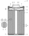
- FIG. 1 is a cross-sectional view of a nonaqueous electrolyte secondary battery according to an embodiment
- FIG. 2 is a diagram showing a particle cross-section of a silicon-containing material according to an embodiment.
- the main cause of such a decline in cycle characteristics is believed to be the large expansion and contraction of the negative electrode mixture layer as the charge and discharge depth is deepened, resulting in insufficient diffusion of the electrolyte in the negative electrode mixture layer and thus non-uniform battery reactions.
- the inventors therefore used a lithium-containing transition metal composite oxide with a specific sulfonic acid compound attached to the particle surface as the positive electrode active material, and a silicon-containing material with an Si phase size of 110 nm or less dispersed in an ion conductive phase as the negative electrode active material, thereby successfully improving output characteristics and cycle characteristics while ensuring high capacity.
- the nonaqueous electrolyte secondary battery according to the present disclosure the expansion and contraction of the negative electrode mixture layer is kept small even when the negative electrode is deeply charged and discharged, which is believed to improve cycle characteristics.
- the sulfonic acid compound represented by the above formula (I) functions specifically when applied to the particle surface of a lithium-containing transition metal composite oxide to reduce the reaction resistance in the positive electrode and deepen the charge/discharge depth of the positive electrode.
- a battery with high capacity and excellent output characteristics and cycle characteristics cannot be realized by simply applying a sulfonic acid compound to the positive electrode.
- the size of the Si phase of the silicon-containing material 110 nm or less the cycle characteristics are specifically improved compared to the case of using a silicon-containing material with a Si phase size exceeding 110 nm.
- a nonaqueous electrolyte secondary battery 10 is exemplified, which is a cylindrical battery in which a wound electrode body 14 is housed in a cylindrical exterior can 16 with a bottom, but the exterior body of the battery is not limited to a cylindrical exterior can.
- Other embodiments of the nonaqueous electrolyte secondary battery according to the present disclosure include a prismatic battery with a prismatic exterior can, a coin battery with a coin-shaped exterior can, and a pouch-type battery with an exterior body composed of a laminate sheet including a metal layer and a resin layer.
- the electrode body is not limited to a wound type, and may be a laminated type electrode body in which multiple positive electrodes and multiple negative electrodes are alternately stacked with separators between them.
- the nonaqueous electrolyte secondary battery 10 includes a wound electrode assembly 14, a nonaqueous electrolyte, and an exterior can 16 that contains the electrode assembly 14 and the nonaqueous electrolyte.
- the electrode assembly 14 has a positive electrode 11, a negative electrode 12, and a separator 13, and has a wound structure in which the positive electrode 11 and the negative electrode 12 are wound in a spiral shape with the separator 13 interposed therebetween.
- the exterior can 16 is a cylindrical metal container with a bottom that is open at one axial end, and the opening of the exterior can 16 is closed by a sealing body 17.
- the sealing body 17 side of the battery is referred to as the top
- the bottom side of the exterior can 16 is referred to as the bottom.
- the non-aqueous electrolyte has ionic conductivity (e.g., lithium ion conductivity).
- the non-aqueous electrolyte may be a liquid electrolyte (electrolytic solution) or a solid electrolyte.
- the liquid electrolyte includes a non-aqueous solvent and an electrolyte salt dissolved in the non-aqueous solvent.
- a non-aqueous solvent for example, esters, ethers, nitriles, amides, and mixed solvents of two or more of these are used as the non-aqueous solvent.
- the non-aqueous solvent include ethylene carbonate (EC), ethyl methyl carbonate (EMC), dimethyl carbonate (DMC), diethyl carbonate (DEC), and mixed solvents of these.
- the non-aqueous solvent may contain a halogen-substituted product (e.g., fluoroethylene carbonate, etc.) in which at least a part of the hydrogen of these solvents is replaced with a halogen atom such as fluorine.
- a halogen-substituted product e.g., fluoroethylene carbonate, etc.
- a lithium salt such as LiPF6 is used as the electrolyte salt.
- the solid electrolyte for example, a solid or gel-like polymer electrolyte, an inorganic solid electrolyte, etc. are used.
- the polymer electrolyte includes, for example, a lithium salt and a matrix polymer, or a non-aqueous solvent, a lithium salt, and a matrix polymer.
- the matrix polymer for example, a polymer material that absorbs the non-aqueous solvent and gels is used.
- the polymer material for example, a fluororesin, an acrylic resin, a polyether resin, etc. are used.
- the inorganic solid electrolyte for example, a material known in all-solid-state lithium ion secondary batteries, etc. (for example, an oxide-based solid electrolyte, a sulfide-based solid electrolyte, a halide-based solid electrolyte, etc.) is used.
- the positive electrode 11, negative electrode 12, and separator 13 that make up the electrode body 14 are all long, strip-like bodies that are wound in a spiral shape and stacked alternately in the radial direction of the electrode body 14.
- the negative electrode 12 is formed to be slightly larger than the positive electrode 11 in order to prevent lithium precipitation. That is, the negative electrode 12 is formed to be longer in the length direction and width direction than the positive electrode 11.
- the separator 13 is formed to be at least slightly larger than the positive electrode 11, and for example, two separators 13 are arranged to sandwich the positive electrode 11.
- the electrode body 14 has a positive electrode lead 20 connected to the positive electrode 11 by welding or the like, and a negative electrode lead 21 connected to the negative electrode 12 by welding or the like.
- Insulating plates 18, 19 are arranged above and below the electrode body 14.
- the positive electrode lead 20 passes through a through hole in the insulating plate 18 and extends toward the sealing body 17, and the negative electrode lead 21 passes outside the insulating plate 19 and extends toward the bottom side of the outer can 16.
- the positive electrode lead 20 is connected to the underside of the internal terminal plate 23 of the sealing body 17 by welding or the like, and the cap 27, which is the top plate of the sealing body 17 and is electrically connected to the internal terminal plate 23, serves as the positive electrode terminal.
- the negative electrode lead 21 is connected to the inner bottom inner surface of the outer can 16 by welding or the like, and the outer can 16 serves as the negative electrode terminal.
- a gasket 28 is provided between the exterior can 16 and the sealing body 17 to ensure airtightness inside the battery.
- the exterior can 16 has a grooved portion 22 formed with a portion of the side surface that protrudes inward to support the sealing body 17.
- the grooved portion 22 is preferably formed in an annular shape along the circumferential direction of the exterior can 16, and supports the sealing body 17 on its upper surface.
- the sealing body 17 is fixed to the top of the exterior can 16 by the grooved portion 22 and the open end of the exterior can 16 that is crimped against the sealing body 17.
- the sealing body 17 has a structure in which, in order from the electrode body 14 side, an internal terminal plate 23, a lower valve body 24, an insulating member 25, an upper valve body 26, and a cap 27 are stacked.
- Each member constituting the sealing body 17 has, for example, a disk or ring shape, and each member except for the insulating member 25 is electrically connected to each other.
- the lower valve body 24 and the upper valve body 26 are connected at their respective centers, and the insulating member 25 is interposed between their respective peripheral edges.
- the positive electrode 11, negative electrode 12, and separator 13 that make up the electrode body 14 will be described in detail, in particular the positive electrode active material that makes up the positive electrode 11, and the negative electrode active material that makes up the negative electrode 12.
- the positive electrode 11 has a positive electrode core 30 and a positive electrode mixture layer 31 arranged on the positive electrode core 30.
- a foil of a metal stable in the potential range of the positive electrode 11, such as aluminum, an aluminum alloy, stainless steel, or titanium, or a film having the metal arranged on the surface can be used.
- the positive electrode mixture layer 31 contains a positive electrode active material, a conductive agent, and a binder, and is preferably provided on both sides of the positive electrode core 30 except for the part to which the positive electrode lead 20 is connected.
- the positive electrode 11 can be produced, for example, by applying a positive electrode mixture slurry containing a positive electrode active material, a conductive agent, and a binder to the surface of the positive electrode core 30, drying the coating, and then compressing it to form the positive electrode mixture layer 31 on both sides of the positive electrode core 30.
- Examples of the conductive agent contained in the positive electrode mixture layer 31 include carbon black such as acetylene black and ketjen black, graphite, carbon nanotubes (CNT), carbon nanofibers, graphene, metal fibers, metal powders, conductive whiskers, etc.
- carbon black such as acetylene black and ketjen black
- graphite carbon nanotubes (CNT)
- carbon nanofibers carbon nanofibers
- graphene graphene
- metal fibers metal powders
- conductive whiskers etc.
- One type of conductive agent may be used alone, or multiple types may be used in combination.
- binder contained in the positive electrode mixture layer 31 examples include fluorine-containing resins such as polytetrafluoroethylene (PTFE) and polyvinylidene fluoride (PVDF), olefin resins such as polyethylene, polypropylene, ethylene-propylene-isoprene copolymer, and ethylene-propylene-butadiene copolymer, and acrylic resins such as polyacrylonitrile (PAN), polyimide, polyamide, and ethylene-acrylic acid copolymer. These resins may also be used in combination with carboxymethylcellulose (CMC) or a salt thereof, polyethylene oxide (PEO), and the like.
- CMC carboxymethylcellulose
- PEO polyethylene oxide
- One type of binder may be used alone, or multiple types may be used in combination.
- the content of the conductive agent and the binder is, for example, 0.1% by mass or more and 5% by mass or less, relative to the mass of the positive electrode mixture layer 31.
- the positive electrode 11 contains a lithium-containing transition metal composite oxide and a sulfonic acid compound present on the particle surface of the composite oxide.
- the lithium-containing transition metal composite oxide having the sulfonic acid compound attached to the particle surface functions as a positive electrode active material.
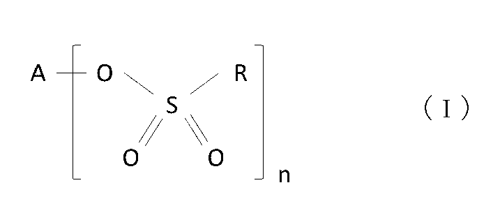
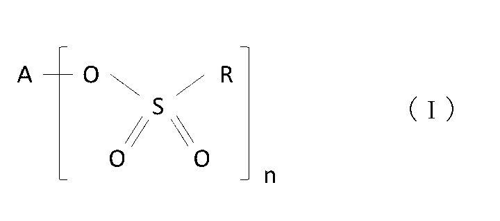
- the sulfonic acid compound is a compound represented by formula (I). In the formula, A is a Group 1 or Group 2 element, R is a hydrocarbon group, and n is 1 or 2.
- the sulfonic acid compound represented by formula (I) functions specifically when applied to the particle surface of the lithium-containing transition metal oxide to reduce the reaction resistance in the positive electrode 11 and improve the output characteristics of the battery. In addition, the lower resistance makes it possible to deepen the charge/discharge depth, thereby achieving high capacity. Although the sulfonic acid compound exerts this effect even in a very small amount, it is preferable that the sulfonic acid compound be present on the particle surface of the complex oxide in an amount of 0.01 mass% or more relative to the lithium-containing transition metal complex oxide.
- the content of the sulfonic acid compound is more preferably 0.05 mass% or more relative to the lithium-containing transition metal complex oxide, and particularly preferably 0.10 mass% or more.
- the upper limit of the sulfonic acid compound content is not particularly limited, but from the viewpoint of achieving both output characteristics and cycle characteristics, it is preferably 2.0 mass% relative to the lithium-containing transition metal composite oxide, more preferably 1.5 mass%, and particularly preferably 1.0 mass%.
- An example of a suitable content of the sulfonic acid compound is 0.05 mass% or more and 1.50 mass% or less, 0.1 mass% or more and 1.0 mass% or less, or 0.2 mass% or more and 0.7 mass% or less relative to the lithium-containing transition metal composite oxide.
- the positive electrode active material may be composed essentially of only composite particles that are lithium-containing transition metal composite oxides with a sulfonic acid compound attached to the particle surface as the main component (the component with the highest mass percentage).
- the positive electrode active material may also contain composite oxides other than the composite particles or other compounds within a range that does not impair the objectives of the present disclosure.
- a composite oxide that does not have a sulfonic acid compound attached to the particle surface may be included as part of the positive electrode active material.
- the lithium-containing transition metal oxide preferably has a layered rock salt structure.
- a sulfonic acid compound is applied to a composite oxide with a layered rock salt structure, the above effect becomes more pronounced.
- the layered rock salt structure of the lithium-containing transition metal oxide include a layered rock salt structure belonging to the space group R-3m and a layered rock salt structure belonging to the space group C2/m. Among these, from the viewpoint of high capacity and stability of the crystal structure, a layered rock salt structure belonging to the space group R-3m is preferred.
- the layered rock salt structure of the lithium-containing transition metal oxide includes a transition metal layer, a Li layer, and an oxygen layer.
- the lithium-containing transition metal oxide is a composite oxide that contains, in addition to Li, metal elements such as Ni, Co, Mn, and Al.
- the metal element that constitutes the lithium-containing transition metal oxide is, for example, at least one selected from Mg, Al, Ca, Sc, Ti, V, Cr, Mn, Fe, Co, Ni, Cu, Zn, Ga, Ge, Y, Zr, Sn, Sb, W, Pb, and Bi. Of these, it is preferable that the oxide contains at least one selected from Co, Ni, and Mn.
- the lithium-containing transition metal oxide preferably contains 70 mol% or more, and more preferably 80 mol% or more of Ni relative to the total number of moles of metal elements excluding Li. Furthermore, the effect of adding a sulfonic acid compound is more pronounced when a lithium-containing transition metal oxide with a high Ni content is used.
- the Ni content may be 85 mol% or more, or may be 90 mol% or more, relative to the total number of moles of metal elements excluding Li.
- the upper limit of the Ni content is, for example, 95 mol%.
- the Al content is 4 mol% or more and 15 mol% or less, and the Co content is 1.5 mol% or less, relative to the total number of moles of metal elements excluding Li. If the Al content is within this range, the crystal structure is stabilized and contributes to improved cycle characteristics, compared to when the content is outside this range. Although Co does not have to be substantially added, adding a small amount of Co tends to improve battery performance.
- the Mn content is, for example, 4 mol% or more and 15 mol% or less, relative to the total number of moles of metal elements excluding Li.
- the content of elements constituting the lithium-containing transition metal composite oxide can be measured using an inductively coupled plasma atomic emission spectrometer (ICP-AES), an electron probe microanalyzer (EPMA), or an energy dispersive X-ray analyzer (EDX), etc.
- ICP-AES inductively coupled plasma atomic emission spectrometer
- EPMA electron probe microanalyzer
- EDX energy dispersive X-ray analyzer
- the lithium-containing transition metal complex oxide is, for example, a secondary particle formed by the aggregation of multiple primary particles.
- the volume-based median diameter (D50) of the complex oxide is not particularly limited, but for example, it is 3 ⁇ m to 30 ⁇ m, preferably 5 ⁇ m to 25 ⁇ m.
- the D50 of the complex oxide means the D50 of the secondary particle.
- D50 means the particle size at which the cumulative frequency is 50% from the smallest particle size in the volume-based particle size distribution.
- the particle size distribution of the complex oxide (as well as that of the negative electrode active material) can be measured using a laser diffraction particle size distribution measuring device (for example, MT3000II manufactured by Microtrack Bell Co., Ltd.) with water as the dispersion medium.
- a laser diffraction particle size distribution measuring device for example, MT3000II manufactured by Microtrack Bell Co., Ltd.
- the average particle size of the primary particles constituting the lithium-containing transition metal composite oxide is, for example, 0.05 ⁇ m or more and 1 ⁇ m or less.
- the average particle size of the primary particles is calculated by averaging the diameters of the circumscribed circles of the primary particles extracted by analyzing scanning electron microscope (SEM) images of the cross sections of the secondary particles.
- the sulfonic acid compound present on the particle surface of the lithium-containing transition metal composite oxide is the compound represented by formula (I) as described above.
- A is a Group 1 or Group 2 element
- R is a hydrocarbon group
- n is 1 or 2.
- A is preferably a Group 1 element. Among them, Li or Na is more preferable, and Li is particularly preferable.
- R is preferably an alkyl group.
- the number of carbon atoms in the alkyl group is preferably 5 or less, and more preferably 3 or less. From the viewpoint of reducing reaction resistance, a suitable example of R is an alkyl group having 3 or less carbon atoms, and among these, a methyl group is preferable. Note that in R, some of the hydrogens bonded to the carbons may be substituted with fluorine. Also, n in formula (I) is preferably 1.
- sulfonic acid compounds include lithium methanesulfonate, lithium ethanesulfonate, lithium propanesulfonate, sodium methanesulfonate, sodium ethanesulfonate, magnesium methanesulfonate, and lithium fluoromethanesulfonate.
- at least one selected from the group consisting of lithium methanesulfonate, lithium ethanesulfonate, and sodium methanesulfonate is preferred, with lithium methanesulfonate being particularly preferred.
- the sulfonic acid compound is present, for example, homogeneously on the entire particle surface of the lithium-containing transition metal composite oxide.
- the presence of the sulfonic acid compound on the particle surface of the composite oxide can be confirmed by Fourier transform infrared spectroscopy (FT-IR).
- FT-IR Fourier transform infrared spectroscopy
- the positive electrode active material containing lithium methanesulfonate has absorption peaks, for example, near 1238 cm -1 , 1175 cm -1 , 1065 cm -1 , and 785 cm -1 .
- the peaks near 1238 cm -1 , 1175 cm -1 , and 1065 cm -1 are peaks due to SO stretching vibration derived from lithium methanesulfonate.
- the peak near 785 cm -1 is a peak due to CS stretching vibration derived from lithium methanesulfonate.
- positive electrode active materials containing sulfonic acid compounds other than lithium methanesulfonate can also be confirmed from the absorption peaks due to sulfonic acid compounds in the infrared absorption spectrum.
- the presence of sulfonic acid compounds on the particle surface of lithium-containing transition metal composite oxides can also be confirmed by ICP, atomic absorption spectrometry, X-ray photoelectron spectroscopy (XPS), synchrotron radiation XRD measurement, TOF-SIMS, etc.
- the positive electrode active material which is an example of an embodiment, can be manufactured by the following method. Note that the manufacturing method described here is only one example, and the manufacturing method of the positive electrode active material is not limited to this method.
- a metal oxide containing metal elements such as Ni, Co, Mn, and Al is synthesized.
- the metal oxide is mixed with a lithium compound and baked to obtain a lithium-containing transition metal composite oxide.
- the metal oxide can be synthesized, for example, by dropping an alkaline solution such as sodium hydroxide into a solution of a metal salt containing Ni, Co, Mn, Al, etc. while stirring it, adjusting the pH to the alkaline side (e.g., 8.5 to 12.5), thereby precipitating (co-precipitating) a composite hydroxide containing metal elements such as Ni, Co, Mn, and Al, and then heat-treating the composite hydroxide.
- the heat treatment temperature is not particularly limited, but an example is 300°C to 600°C.
- lithium compound examples include Li2CO3 , LiOH , Li2O2 , Li2O , LiNO3 , LiNO2 , Li2SO4 , LiOH.H2O , LiH, and LiF.
- the metal oxide and the lithium compound are mixed so that the molar ratio of the metal element in the metal oxide to Li in the lithium compound is 1:0.98 or more and 1: 1.1 or less.
- other metal raw materials may be added as necessary.
- the mixture of metal oxide and lithium compound is fired, for example, under an oxygen atmosphere.
- the mixture may be fired through multiple heating processes.
- the firing process includes, for example, a first heating process in which the temperature is raised to 450°C or higher and 680°C or lower at a heating rate of 1.0°C/min or higher and 5.5°C/min or lower, and a second heating process in which the temperature is raised to a temperature exceeding 680°C at a heating rate of 0.1°C/min or higher and 3.5°C/min or lower.
- the maximum temperature reached in the firing process may be set to 700°C or higher and 850°C or lower, and this temperature may be maintained for 1 hour or higher and 10 hours or lower.
- the fired product (lithium-containing transition metal composite oxide) is washed with water and dehydrated to obtain a cake-like composition.
- This washing step removes any remaining alkaline components.
- the washing and dehydration can be carried out by a conventionally known method.
- the cake-like composition is then dried to obtain a powder-like composition.
- the drying step may be carried out in a vacuum atmosphere.
- An example of the drying conditions is a temperature of 150°C to 400°C for 0.5 hours to 15 hours.
- the sulfonic acid compound is added, for example, to the cake-like composition obtained in the washing step, or to the powder-like composition obtained in the drying step.
- a sulfonic acid solution may be added in place of or together with the sulfonic acid compound. This results in a positive electrode active material in which the sulfonic acid compound is attached to the particle surface of the lithium-containing transition metal composite oxide.
- the sulfonic acid compound may be added as an aqueous dispersion.
- the sulfonic acid solution is preferably an aqueous solution of sulfonic acid.
- the concentration of sulfonic acid in the sulfonic acid solution is, for example, 0.5% by mass or more and 40% by mass or less.
- adding a sulfonic acid solution to the cake-like composition causes the Li dissolved in the water in the cake to react with the sulfonic acid, producing lithium sulfonate.
- the negative electrode 12 has a negative electrode core 40 and a negative electrode mixture layer 41 arranged on the negative electrode core 40.
- a foil of a metal stable in the potential range of the negative electrode 12, such as copper, copper alloy, stainless steel, nickel, or nickel alloy, or a film having the metal arranged on the surface can be used.
- the negative electrode mixture layer 41 contains a negative electrode active material and a binder, and is preferably provided on both sides of the negative electrode core 40 except for the part to which the negative electrode lead 21 is connected.
- the negative electrode 12 can be produced, for example, by applying a negative electrode mixture slurry containing a negative electrode active material and a binder to the surface of the negative electrode core 40, drying the coating, and then compressing it to form the negative electrode mixture layer 41 on both sides of the negative electrode core 40.
- the negative electrode mixture layer 41 may contain a conductive agent such as CNT.
- the binder contained in the negative electrode mixture layer 41 may be a fluorine-containing resin, an olefin resin, PAN, a polyimide, a polyamide, an acrylic resin, or the like.
- polyvinyl acetate, styrene-butadiene rubber (SBR), or the like may also be used. Of these, it is preferable to use SBR.
- SBR styrene-butadiene rubber
- One type of binder may be used alone, or multiple types may be used in combination.
- the content of the binder is, for example, 0.1% by mass or more and 5% by mass or less with respect to the mass of the negative electrode mixture layer 41.
- the negative electrode mixture layer 41 contains CMC or a salt thereof, polyacrylic acid (PAA) or a salt thereof, polyvinyl alcohol (PVA), or the like. These function as thickeners in the negative electrode mixture slurry.
- Negative electrode 12 includes silicon-containing material 50 having a particle cross section as shown in FIG. 2.
- Silicon-containing material 50 is included in negative electrode mixture layer 41 and functions as a negative electrode active material that absorbs and releases Li ions during charging and discharging of the battery.
- Silicon-containing material 50 includes ion-conducting phase 51 and Si phase 52 dispersed in ion-conducting phase 51.
- the size of Si phase 52 is 110 nm or less.
- the cycle characteristics change specifically at the boundary of Si phase size of 110 nm.
- the size of Si phase 52 of silicon-containing material 50 is 110 nm or less, the cycle characteristics are specifically improved.
- the negative electrode 12 may use only the silicon-containing material 50 as the negative electrode active material, but preferably contains both a carbon material and the silicon-containing material 50. By using the carbon material and the silicon-containing material 50 in combination, it becomes easier to achieve both high capacity and excellent cycle characteristics.
- the negative electrode 12 may contain, for example, a silicon-containing material other than the silicon-containing material 50 as the negative electrode active material, or a material containing other elements that form an alloy with Li, but in this embodiment, it essentially contains only the carbon material and the silicon-containing material 50.
- the content of the carbon material is preferably higher than the content of the silicon-containing material 50.
- the content of the silicon-containing material 50 is preferably 40 mass% or less of the total mass of the negative electrode active material, more preferably 35 mass% or less, and particularly preferably 30 mass% or less.
- the content of the silicon-containing material 50 is preferably 5 mass% or more of the total mass of the negative electrode active material.
- An example of a suitable range for the content of silicon-containing material 50 is 5% by mass or more and 35% by mass or less of the total mass of the negative electrode active material, and more preferably 5% by mass or more and 30% by mass or less, or 5% by mass or more and 25% by mass or less.
- negative electrode 12 may contain silicon-containing materials other than silicon-containing material 50 within a range that does not impair the objective of the present disclosure.
- the average size of the Si phase of the silicon-containing material contained in negative electrode 12 may be 110 nm or less, and a silicon-containing material whose Si phase size exceeds 110 nm may be included.
- the carbon material that functions as the negative electrode active material is, for example, at least one selected from the group consisting of natural graphite, artificial graphite, soft carbon, and hard carbon. Among them, it is preferable to use, as the carbon material, at least artificial graphite such as massive artificial graphite (MAG) and graphitized mesophase carbon microbeads (MCMB), natural graphite such as flake graphite, massive graphite, and earthy graphite, or a mixture of these.
- the volume-based D50 of the carbon material is, for example, 1 ⁇ m or more and 30 ⁇ m or less, and preferably 5 ⁇ m or more and 25 ⁇ m or less.
- Soft carbon and hard carbon are classified as amorphous carbons that do not have a developed graphite crystal structure. More specifically, they refer to carbon components with a d(002) interplanar spacing of 0.342 nm or more as determined by X-ray diffraction. Soft carbon is also called graphitizable carbon, and is carbon that is more easily graphitized by high-temperature treatment than hard carbon. Hard carbon is also called non-graphitizable carbon. In the configuration of the present invention, it is not necessary to clearly distinguish between soft carbon and hard carbon. Graphite and at least one of the amorphous carbons, soft carbon and hard carbon, may be used in combination as the negative electrode active material.
- the silicon-containing material 50 includes an ion-conducting phase 51 and an Si phase 52 dispersed in the ion-conducting phase 51.
- the silicon-containing material 50 is a composite particle composed of the ion-conducting phase 51 and the Si phase 52.
- the D50 of the silicon-containing material 50 is generally smaller than the D50 of graphite.
- the volume-based D50 of the silicon-containing material 50 is, for example, 1 ⁇ m or more and 20 ⁇ m or less, or 1 ⁇ m or more and 15 ⁇ m or less. Note that one type of silicon-containing material 50 may be used alone, or two or more types may be used in combination.
- the ion-conducting phase 51 is at least one selected from the group consisting of, for example, a silicate phase, a carbon phase, a silicide phase, and a silicon oxide phase.
- the silicide phase is a phase of a compound consisting of Si and an element more electrically positive than Si, and examples thereof include NiSi, Mg 2 Si, and TiSi 2.
- the Si phase 52 is formed by dispersing Si in the form of fine particles.
- the ion-conducting phase 51 is a continuous phase constituted by a collection of particles finer than the Si phase 52.
- the size of the Si phase 52 in the silicon-containing material 50 is 110 nm or less, as described above. It is preferable that the average size of the Si phase 52 contained in one particle of the silicon-containing material 50 is 110 nm or less.
- the Si phase 52 is dispersed in the ion-conducting phase 51 in the particle cross section of the silicon-containing material 50 in the form of fine particles. For this reason, hereinafter, the average size of the Si phase 52 may be referred to as the "average particle size.”
- the average particle size of the Si phase is calculated by randomly selecting 100 silicon-containing materials, taking SEM images of the cross sections of each particle, and averaging the diameters of the circumscribing circles ⁇ of the Si phases extracted by image analysis.
- the particle cross sections can be prepared by the cross-section polisher (CP) method.
- the average particle size of the Si phase is 110 nm or less. Note that, as long as the average particle size of the Si phase is 110 nm or less throughout the entire negative electrode mixture layer 41, a silicon-containing material whose average particle size of the Si phase exceeds 110 nm may be used. However, when two or more types of materials are used, it is preferable that all of the materials are silicon-containing materials 50 whose Si phase 52 has an average particle size of 110 nm or less.
- the Si phase 52 contained in one particle of the silicon-containing material 50 may have an average particle size of 110 nm or less, but all of the particles may have particle sizes of 110 nm or less.
- the average particle size of the Si phase 52 is preferably 100 nm or less, more preferably 90 nm or less, and particularly preferably 80 nm or less. In this case, particle expansion associated with charging and discharging can be effectively suppressed while maintaining a high capacity, and the effect of improving cycle characteristics becomes more pronounced.
- the average particle size of the Si phase 52 may be 50 nm or less, 30 nm or less, 20 nm or less, or 10 nm or less.
- the lower limit of the average particle size of the Si phase 52 is not particularly limited, but is, for example, 1 nm.
- An example of a suitable range of the average particle size of the Si phase 52 may be 1 nm or more and 50 nm or less, 1 nm or more and 40 nm or less, 1 nm or more and 30 nm or less, 5 nm or more and 30 nm or less, or 10 nm or more and 30 nm or less. If the average particle size of the Si phase 52 is within this range, the effect of improving the cycle characteristics is greater than when the average particle size is outside this range.
- the silicon-containing material 50 may have a conductive layer covering the surface of the ion-conducting phase 51.
- the conductive layer is made of a material having a higher conductivity than the ion-conducting phase 51 and forms a good conductive path in the negative electrode mixture layer 41.
- the conductive layer is, for example, a carbon coating made of a conductive carbon material.
- the conductive carbon material may be carbon black such as acetylene black or ketjen black, graphite, or amorphous carbon (amorphous carbon) with low crystallinity.
- the thickness of the conductive layer is preferably 1 nm or more and 200 nm or less, or 5 nm or more and 100 nm or less, taking into consideration the need to ensure conductivity and the diffusibility of Li ions into the particles.
- the thickness of the conductive layer can be measured by observing the cross section of the composite material using a SEM or a transmission electron microscope (TEM).
- the ion-conducting phase 51 may contain at least one element selected from the group consisting of Group 1 and Group 2 elements of the periodic table.
- the ion-conducting phase 51 may be a silicon oxide phase doped with Li.
- the ion-conducting phase 51 may also contain at least one element selected from the group consisting of B, Al, Zr, Nb, Ta, V, Y, Ti, P, Bi, Zn, Sn, Pb, Sb, Co, Er, F, W, and lanthanides.
- a suitable example of the silicon-containing material 50 is a composite particle having a sea-island structure in which fine Si (Si phase 52) is approximately uniformly dispersed in an amorphous silicon oxide phase (ion conductive phase 51), and is generally represented by the general formula SiO x (0 ⁇ x ⁇ 2).
- the main component of the silicon oxide may be silicon dioxide.
- the silicon oxide phase may be doped with Li.
- the content ratio (x) of oxygen to Si is, for example, 0.5 ⁇ x ⁇ 2.0, and preferably 0.8 ⁇ x ⁇ 1.5.
- a suitable silicon-containing material 50 is a composite particle having a sea-island structure in which fine Si is dispersed substantially uniformly in an amorphous silicate phase.
- a suitable silicate phase is a lithium silicate phase containing Li.
- a suitable silicon-containing material 50 is a composite particle having an island structure in which fine Si particles are uniformly dispersed in a carbon phase.
- the carbon phase is preferably an amorphous carbon phase.
- the carbon phase may contain a crystalline phase component, but preferably contains more amorphous phase components.
- the amorphous carbon phase is composed of a carbon material having an average interplanar spacing of (002) faces of more than 0.34 nm as measured by X-ray diffraction, for example.
- the composite material containing a carbon phase may or may not have a conductive layer separate from the carbon phase.
- the silicon-containing material 50 is obtained, for example, by synthesizing SiO 2 nanoparticles using alkoxysilane as a raw material, synthesizing a polymer containing SiO 2 nanoparticles, carbonizing the polymer, and performing a reduction process (see the examples described later for details). In this case, a composite particle in which fine Si is dispersed substantially uniformly in an amorphous carbon phase is obtained.
- the size of the Si phase 52 can be reduced by, for example, performing a long-term grinding process on the SiO 2 nanoparticles using a grinder such as a bead mill. The grinding is continued for, for example, 100 hours or more until the average particle size of the SiO 2 nanoparticles reaches the desired particle size. At this time, the grinding process is performed by adding isopropyl alcohol, which promotes the refinement of the SiO 2 nanoparticles.
- the particle expansion rate of the silicon-containing material 50 is preferably 210% or less, and more preferably 170% or less.
- the particle expansion coefficient of the silicon-containing material 50 is measured by the following method. (1) The battery to be evaluated is disassembled, and the negative electrode plate is cut out. Using metallic Li as the counter electrode and an ionic liquid as the electrolyte, a single-electrode cell is produced in which the particle cross-section of the silicon-containing material is exposed. (2) The single-electrode cell is charged at 0.002 C in a temperature environment of 25° C. until the cell voltage reaches 5 mV, and then discharged at 0.05 C until the cell voltage reaches 1.0 V, and the particle cross-section of the silicon-containing material is observed in situ using a SEM.
- the particle volume (V1) of the silicon-containing material in the charged state and the particle volume (V2) of the silicon-containing material in the discharged state are determined, and the particle expansion coefficient (V1 x 100/V2) is calculated.
- the expansion rate of the negative electrode mixture layer 41 during charging per discharge capacity is preferably 50%/(mAh/g) or less, more preferably 48%/(mAh/g) or less.
- the discharge capacity is the discharge capacity per 1 g of the negative electrode active material.
- the expansion rate of the negative electrode mixture layer 41 during charging can be controlled by the amount of silicon-containing material 50 added and the particle expansion rate.
- the lower limit of the expansion rate of the negative electrode mixture layer 41 during charging per discharge capacity is not particularly limited, but one example is 40%/(mAh/g). If the expansion rate of the negative electrode mixture layer 41 during charging is 40%/(mAh/g) or more, it is easier to achieve a high capacity compared to when the expansion rate is less than 40%/(mAh/g).
- the expansion rate during charging per discharge capacity of the negative electrode mixture layer 41 is measured by the following method.
- the battery to be evaluated is disassembled, the negative electrode is cut out, and a single-electrode cell is prepared using metallic Li as the counter electrode and an ionic liquid as the electrolyte.
- the single-electrode cell is charged at 0.1 C in a temperature environment of 25° C. until the cell voltage reaches 5 mV, and then discharged at 0.1 C until the cell voltage reaches 1.0 V, and the discharge capacity (mAh/g) per 1 g of negative electrode active material is determined.
- the thickness (T1) of the negative electrode mixture layer in a charged state and the thickness (T2) of the negative electrode mixture layer in a discharged state are determined, and the increase rate of the thickness (T1 ⁇ 100/T2 ⁇ 100) is calculated. This is then divided by the discharge capacity (mAh/g) per 1 g of active material in the negative electrode mixture to calculate the expansion rate during charge per discharge capacity of the negative electrode mixture layer.
- a porous sheet having ion permeability and insulation is used for the separator 13.
- the porous sheet include a microporous thin film, a woven fabric, and a nonwoven fabric.
- the material of the separator 13 is preferably a polyolefin such as polyethylene or polypropylene, or cellulose.
- the separator 13 may have a single layer structure or a multilayer structure.
- the separator 13 may have, for example, a multilayer structure including a thermoplastic resin layer such as a polyolefin and a cellulose fiber layer, a two-layer structure of polyethylene (PE)/polypropylene (PP), or a three-layer structure of PE/PP/PE.
- a filler layer containing an inorganic filler may be disposed at the interface between the separator 13 and at least one of the positive electrode 11 and the negative electrode 12.
- inorganic fillers include oxides containing metal elements such as Ti, Al, Si, and Mg, and phosphate compounds.
- the filler layer can be formed by applying a slurry containing the filler to the surface of the positive electrode 11, the negative electrode 12, or the separator 13.
- a resin layer (heat-resistant layer) having high heat resistance such as aramid resin may be disposed on the surface of the separator 13.
- the separator 13 may have, for example, a substrate made of a porous sheet and a filler layer or a heat-resistant layer disposed on the substrate.
- Example 1 [Synthesis of positive electrode active material]
- the composite hydroxide represented by [Ni 0.90 Al 0.05 Mn 0.05 ] (OH) 2 obtained by the coprecipitation method was calcined at 500 ° C. for 8 hours to obtain an oxide (Ni 0.90 Al 0.05 Mn 0.05 O 2 ).
- LiOH and the composite oxide were mixed so that the molar ratio of Li to the total amount of Ni, Al, and Mn was 1.03:1 to obtain a mixture.
- This mixture was calcined from room temperature to 650 ° C. at a heating rate of 2.0 ° C.
- the positive electrode active material, acetylene black, and polyvinylidene fluoride were mixed in a mass ratio of 98:1:1, and N-methyl-2-pyrrolidone (NMP) was used as a dispersion medium to prepare a positive electrode mixture slurry.
- NMP N-methyl-2-pyrrolidone
- the positive electrode mixture slurry was applied onto a positive electrode core made of aluminum foil, the coating was dried and compressed, and then the positive electrode core was cut into a predetermined electrode size to obtain a positive electrode having a positive electrode mixture layer formed on both sides of the positive electrode core. An exposed portion was provided in which the surface of the positive electrode core was exposed in a part of the positive electrode.
- Tetraethylorthosilane (TEOS) and cetyltrimethylammonium bromide (CTAB) were mixed in a mixed solution of ethanol/water/ammonia to obtain SiO 2 nanoparticles modified with CTAB.
- the obtained SiO 2 nanoparticles were milled for 300 hours using a bead mill with the addition of isopropyl alcohol.
- resorcinol and formaldehyde were added and polymerized to obtain polymer particles containing SiO 2 nanoparticles. At this time, the ratio of resorcinol to TEOS was about 0.5:1.
- the polymer was carbonized by heating to 800°C in a nitrogen atmosphere, and further mixed with magnesium powder and heated to 650°C in an argon atmosphere to perform a magnesium thermal reduction reaction.
- MgO was dissolved from the particles after the reaction in a HCl/H 2 O/ethanol solution, washed with ethanol, and then dried to obtain a mesoporous silicon-containing material in which a Si phase was dispersed in an amorphous carbon phase.
- the average particle size of the Si phase was 5 nm.
- the silicon-containing material and artificial graphite were mixed in a mass ratio of 10:90.
- the negative electrode active material, sodium carboxymethylcellulose (CMC-Na), and a dispersion of styrene-butadiene rubber (SBR) were mixed in a solid content mass ratio of 100:1:1, and a negative electrode mixture slurry was prepared using water as a dispersion medium.
- the negative electrode mixture slurry was applied to both sides of a negative electrode core made of copper foil, the coating film was dried, and then the coating film was rolled using a roller and cut to a predetermined electrode size to obtain a negative electrode in which a negative electrode mixture layer was formed on both sides of the negative electrode core.
- an exposed portion in which the surface of the negative electrode core was exposed was provided in a part of the negative electrode.
- a non-aqueous electrolyte solution was prepared by dissolving LiPF6 at a concentration of 1.2 mol/L in a mixed solvent of ethylene carbonate (EC), methyl ethyl carbonate (MEC), and dimethyl carbonate (DMC) in a volume ratio of 3:3:4 (25 ° C.).
- EC ethylene carbonate
- MEC methyl ethyl carbonate
- DMC dimethyl carbonate
- test cell non-aqueous electrolyte secondary battery
- An aluminum lead was attached to the exposed portion of the positive electrode, and a nickel lead was attached to the exposed portion of the negative electrode, and the positive and negative electrodes were spirally wound with a polyolefin separator interposed therebetween, and then pressed in the radial direction to produce a flat wound electrode body.
- This electrode body was housed in an exterior body made of an aluminum laminate sheet, and the nonaqueous electrolyte was injected, and the opening of the exterior body was sealed to obtain a test cell.
- Example 2 A test cell was produced in the same manner as in Example 1, except that in the synthesis of the positive electrode active material, the amount of lithium methanesulfonate added to the lithium-containing transition metal composite oxide was changed to 0.3 mass %.
- Example 3 A test cell was produced in the same manner as in Example 1, except that in the synthesis of the positive electrode active material, the amount of lithium methanesulfonate added to the lithium-containing transition metal composite oxide was changed to 0.5% by mass.
- Example 4 A test cell was produced in the same manner as in Example 1, except that in the synthesis of the positive electrode active material, the amount of lithium methanesulfonate added to the lithium-containing transition metal composite oxide was changed to 1.0 mass %.
- Example 5 A test cell was prepared in the same manner as in Example 3, except that a mixture of the above silicon-containing material and artificial graphite in a mass ratio of 20:80 was used as the negative electrode active material.
- Example 6 A nonaqueous electrolyte secondary battery was fabricated in the same manner as in Example 3, except that a silicon-containing material having an average particle size of the Si phase of 20 nm was used as the negative electrode active material.
- the silicon-containing material was synthesized as follows. Synthesis of silicon-containing materials Tetraethylorthosilicate (TEOS) and cetyltrimethylammonium bromide (CTAB) were mixed in a mixed solution of ethanol/water/ammonia to obtain SiO 2 nanoparticles modified with CTAB. The obtained SiO 2 nanoparticles were milled for 200 hours using a bead mill with the addition of isopropyl alcohol.
- TEOS Tetraethylorthosilicate
- CTAB cetyltrimethylammonium bromide
- resorcinol and formaldehyde were added and polymerized to obtain polymer particles containing SiO 2 nanoparticles.
- the ratio of resorcinol to TEOS was about 0.5:1.
- the polymer was carbonized by heating to 800°C in a nitrogen atmosphere, and further mixed with magnesium powder and heated to 650°C in an argon atmosphere to perform a magnesium thermal reduction reaction.
- MgO was dissolved from the particles after the reaction in a HCl/H 2 O/ethanol solution, washed with ethanol, and then dried to obtain a mesoporous silicon-containing material in which a Si phase was dispersed in an amorphous carbon phase.
- Example 7 A test cell was prepared in the same manner as in Example 6, except that a mixture of the silicon-containing material used in Example 6 and artificial graphite in a mass ratio of 20:80 was used as the negative electrode active material.
- Example 8 A test cell was prepared in the same manner as in Example 3, except that sodium methanesulfonate was used instead of lithium methanesulfonate in the synthesis of the positive electrode active material.
- Example 9 A test cell was prepared in the same manner as in Example 3, except that in the synthesis of the positive electrode active material, lithium ethanesulfonate was used instead of lithium methanesulfonate.
- Example 10 A nonaqueous electrolyte secondary battery was fabricated in the same manner as in Example 3, except that a silicon-containing material having an average particle size of the Si phase of 100 nm was used as the negative electrode active material.
- the silicon-containing material was synthesized as follows. Synthesis of silicon-containing materials A silicon-containing material was synthesized in the same manner as in Example 1, except that the SiO2 nanoparticles were pulverized using a bead mill for 100 hours.
- Example 11 A nonaqueous electrolyte secondary battery was fabricated in the same manner as in Example 3, except that a silicon-containing material having an average particle size of the Si phase of 80 nm was used as the negative electrode active material.
- the silicon-containing material was synthesized as follows. Synthesis of silicon-containing materials A silicon-containing material was synthesized in the same manner as in Example 1, except that the SiO2 nanoparticles were milled using a bead mill for 150 hours.
- a nonaqueous electrolyte secondary battery was produced in the same manner as in Example 1, except that lithium methanesulfonate was not used in the synthesis of the positive electrode active material, and a silicon-containing material having an average particle size of the Si phase of 120 nm was used as the negative electrode active material.
- the synthesis method of the silicon-containing material is as follows. Synthesis of silicon-containing materials A silicon-containing material was synthesized in the same manner as in Example 1, except that the SiO2 nanoparticles were milled using a bead mill for 50 hours.
- Example 2 A test cell was prepared in the same manner as in Example 1, except that lithium methanesulfonate was not used in the synthesis of the positive electrode active material.
- Example 3 A test cell was prepared in the same manner as in Example 3, except that in the synthesis of the positive electrode active material, lithium succinate was used instead of lithium methanesulfonate.
- Example 4 A test cell was prepared in the same manner as in Example 3, except that in the synthesis of the positive electrode active material, lithium oxalate was used instead of lithium methanesulfonate.
- Example 5 A test cell was prepared in the same manner as in Example 3, except that the silicon-containing material used in Comparative Example 1 was used as the silicon-containing material.
- the output characteristics and cycle characteristics (capacity maintenance rate) of each test cell of the examples and comparative examples were evaluated by the following method, and the evaluation results are shown in Table 1.
- the output characteristics of each test cell shown in Table 1 are relative values when the value of the test cell of Comparative Example 2 is set to 100, and a higher value means better output characteristics.
- test cells of the Examples have higher discharge load characteristics and superior output characteristics than the test cells of Comparative Examples 1 to 4.
- all of the test cells of the Examples have higher capacity retention rates after cycle testing and superior cycle characteristics than the test cell of Comparative Example 5.
- the test cells of the Examples achieve both excellent output characteristics and cycle characteristics. As the output characteristics improve, as in the test cell of Comparative Example 5, it becomes difficult to ensure good cycle characteristics, but the test cells of the Examples have good cycle characteristics despite their high output characteristics.
- the test cell of Comparative Example 1 which does not use a sulfonic acid compound in the positive electrode and uses a silicon-containing compound with an average particle size of the Si phase exceeding 110 nm as the negative electrode active material, has lower output characteristics than the test cells of the Examples. Furthermore, the capacity retention rate of the test cell of Comparative Example 1 was similar to that of Example 10, which had the lowest capacity retention rate of the Examples (output characteristic: 102.0).
- a non-aqueous electrolyte secondary battery including a positive electrode, a negative electrode, and a non-aqueous electrolyte
- the positive electrode includes a lithium-containing transition metal composite oxide and a sulfonic acid compound present on the particle surface of the composite oxide,
- the sulfonic acid compound is a compound represented by formula (I), In the formula, A is a Group 1 or Group 2 element, R is a hydrocarbon group, and n is 1 or 2;
- the negative electrode comprises a silicon-containing material; the silicon-containing material comprises an ion-conducting phase and a Si phase dispersed in the ion-conducting phase, the Si phase having a size of 110 nm or less.
- Configuration 2 The nonaqueous electrolyte secondary battery according to configuration 1, wherein the sulfonic acid compound is present in an amount of 0.1% by mass or more and 1.0% by mass or less with respect to the lithium-containing transition metal composite oxide.
- Configuration 3 The nonaqueous electrolyte secondary battery according to configuration 1 or 2, wherein A in formula (I) is Li or Na.
- Configuration 4 The nonaqueous electrolyte secondary battery according to any one of configurations 1 to 3, wherein R in formula (I) is an alkyl group having 3 or less carbon atoms.
- Configuration 5 The nonaqueous electrolyte secondary battery according to any one of configurations 1 to 4, wherein the lithium-containing transition metal composite oxide has a layered rock salt structure.
- Configuration 6 The nonaqueous electrolyte secondary battery according to any one of configurations 1 to 5, wherein the negative electrode mixture layer contains, as negative electrode active materials, a carbon material and the silicon-containing material.
- Aspect 7 The nonaqueous electrolyte secondary battery according to any one of aspects 1 to 6, wherein the ion-conducting phase is at least one selected from the group consisting of a silicate phase, a carbon phase, a silicide phase, and a silicon oxide phase.
- Configuration 8 The nonaqueous electrolyte secondary battery according to any one of configurations 1 to 7, wherein the size of the Si phase is 1 nm or more and 50 nm or less.
Landscapes
- Chemical & Material Sciences (AREA)
- Chemical Kinetics & Catalysis (AREA)
- Electrochemistry (AREA)
- General Chemical & Material Sciences (AREA)
- Inorganic Chemistry (AREA)
- Composite Materials (AREA)
- Engineering & Computer Science (AREA)
- Materials Engineering (AREA)
- Battery Electrode And Active Subsutance (AREA)
Abstract
Description
正極11は、正極芯体30と、正極芯体30上に配置された正極合剤層31とを有する。正極芯体30には、アルミニウム、アルミニウム合金、ステンレス鋼、チタンなどの正極11の電位範囲で安定な金属の箔、当該金属を表面に配置したフィルム等を用いることができる。正極合剤層31は、正極活物質、導電剤、および結着剤を含み、正極リード20が接続される部分を除く正極芯体30の両面に設けられることが好ましい。正極11は、例えば、正極活物質、導電剤、および結着剤を含む正極合剤スラリーを正極芯体30の表面に塗布し、塗膜を乾燥させた後、圧縮して正極合剤層31を正極芯体30の両面に形成することにより作製できる。


負極12は、負極芯体40と、負極芯体40上に配置された負極合剤層41とを有する。負極芯体40には、銅、銅合金、ステンレス鋼、ニッケル、ニッケル合金などの負極12の電位範囲で安定な金属の箔、当該金属を表面に配置したフィルム等を用いることができる。負極合剤層41は、負極活物質および結着剤を含み、負極リード21が接続される部分を除く負極芯体40の両面に設けられることが好ましい。負極12は、例えば、負極芯体40の表面に負極活物質および結着剤を含む負極合剤スラリーを塗布し、塗膜を乾燥させた後、圧縮して負極合剤層41を負極芯体40の両面に形成することにより作製できる。なお、負極合剤層41には、CNT等の導電剤が含まれていてもよい。
(1)評価対象の電池を解体して負極板を切り出し、対極に金属Liを、電解液にイオン液体を用いて、ケイ素含有材料の粒子断面が露出した状態の単極セルを作製する。
(2)単極セルを、25℃の温度環境下、0.002Cでセル電圧が5mVになるまで充電した後、0.05Cでセル電圧が1.0Vになるまで放電し、in-situでケイ素含有材料の粒子断面をSEMで観察する。
(3)ケイ素含有材料の粒子断面積の変化から、充電状態のケイ素含有材料の粒子体積(V1)、および放電状態のケイ素含有材料の粒子体積(V2)を求め、粒子膨張率(V1×100/V2)を算出する。
(1)評価対象の電池を解体して負極を切り出し、対極に金属Liを、電解液にイオン液体を用いて単極セルを作製する。
(2)単極セルを、25℃の温度環境下、0.1Cでセル電圧が5mVになるまで充電した後、0.1Cでセル電圧が1.0Vになるまで放電し、負極活物質1gあたりの放電容量(mAh/g)を求める。
(3)充電状態の負極合剤層の厚み(T1)、および放電状態の負極合剤層の厚み(T2)を求め、当該厚みの増加率(T1×100/T2-100)を算出し、負極合剤中の活物質1gあたりの放電容量(mAh/g)で除して負極合剤層の放電容量あたりの充電時膨張率を算出する。
セパレータ13には、イオン透過性および絶縁性を有する多孔性シートが用いられる。多孔性シートの具体例としては、微多孔薄膜、織布、不織布等が挙げられる。セパレータ13の材質としては、ポリエチレン、ポリプロピレン等のポリオレフィン、セルロースなどが好適である。セパレータ13は、単層構造であってもよく、複層構造であってもよい。セパレータ13は、例えば、ポリオレフィン等の熱可塑性樹脂層およびセルロース繊維層を含む複層構造、ポリエチレン(PE)/ポリプロピレン(PP)の二層構造、又はPE/PP/PEの三層構造を有していてもよい。
[正極活物質の合成]
共沈法により得られた[Ni0.90Al0.05Mn0.05](OH)2で表される複合水酸化物を500℃で8時間焼成して酸化物(Ni0.90Al0.05Mn0.05O2)を得た。次に、LiOHおよび当該複合酸化物を、Liと、Ni、Al、およびMnの総量とのモル比が1.03:1になるように混合して混合物を得た。この混合物を酸素濃度95%の酸素気流下(10cm3あたり2mL/minおよび混合物1kgあたり5L/minの流量)、昇温速度2.0℃/minで室温から650℃まで焼成した後、昇温速度0.5℃/minで650℃から780℃まで焼成してリチウム含有遷移金属複合酸化物を得た。
上記正極活物質と、アセチレンブラックと、ポリフッ化ビニリデンとを、98:1:1の質量比で混合し、分散媒としてN-メチル-2-ピロリドン(NMP)を用いて、正極合剤スラリーを調製した。次に、アルミニウム箔からなる正極芯体上に正極合剤スラリーを塗布し、塗膜を乾燥、圧縮した後、正極芯体を所定の電極サイズに切断して、正極芯体の両面に正極合剤層が形成された正極を得た。なお、正極の一部に正極芯体の表面が露出した露出部を設けた。
エタノール/水/アンモニアの混合用液中にて、テトラエキシシラン(TEOS)と臭化セチルトリメチルアンモニウム(CTAB)を混合してCTABで修飾されたSiO2ナノ粒子を得た。得られたSiO2ナノ粒子を、ビーズミルを用い、イソプロピルアルコールを添加して300時間粉砕処理した。さらに、レゾルシノールとホルムアルデヒドを加えて重合させることによりSiO2ナノ粒子を内包したポリマー粒子を得た。この際、レゾルシノールとTEOSの比率を約0.5:1とした。得られたポリマー粒子を乾燥後、窒素雰囲気中、800℃に加熱してポリマーを炭化させ、さらに、マグネシウム粉末と混合してアルゴン雰囲気中にて650℃で加熱することにより、マグネシウム熱還元反応を行った。HCl/H2O/エタノール溶液にて反応後の粒子からMgOを溶解させ、エタノールで洗浄後、乾燥させることにより、非晶質炭素相中にSi相が分散したメソポーラスなケイ素含有材料を得た。
負極活物質として、上記ケイ素含有材料と、人造黒鉛とを、10:90の質量比で混合したものを用いた。当該負極活物質と、カルボキシメチルセルロースナトリウム(CMC-Na)と、スチレン-ブタジエンゴム(SBR)のディスパージョンを、100:1:1の固形分質量比で混合し、分散媒として水を用いて負極合剤スラリーを調製した。当該負極合剤スラリーを銅箔からなる負極芯体の両面に塗布し、塗膜を乾燥させた後、ローラーを用いて塗膜を圧延し、所定の電極サイズに切断して、負極芯体の両面に負極合剤層が形成された負極を得た。なお、負極の一部に負極芯体の表面が露出した露出部を設けた。
エチレンカーボネート(EC)と、メチルエチルカーボネート(MEC)と、ジメチルカーボネート(DMC)を、3:3:4の体積比(25℃)で混合した混合溶媒に対して、LiPF6を1.2モル/リットルの濃度で溶解させて非水電解液を調製した。
上記正極の露出部にアルミニウムリードを、上記負極の露出部にニッケルリードをそれぞれ取り付け、ポリオレフィン製のセパレータを介して正極と負極を渦巻き状に巻回した後、径方向にプレス成形して扁平状の巻回型電極体を作製した。この電極体をアルミラミネートシートで構成される外装体内に収容し、上記非水電解液を注入した後、外装体の開口部を封止して試験セルを得た。
正極活物質の合成において、リチウム含有遷移金属複合酸化物に対するメタンスルホン酸リチウムの添加量を0.3質量%に変更したこと以外は、実施例1と同様にして試験セルを作製した。
正極活物質の合成において、リチウム含有遷移金属複合酸化物に対するメタンスルホン酸リチウムの添加量を0.5質量%に変更したこと以外は、実施例1と同様にして試験セルを作製した。
正極活物質の合成において、リチウム含有遷移金属複合酸化物に対するメタンスルホン酸リチウムの添加量を1.0質量%に変更したこと以外は、実施例1と同様にして試験セルを作製した。
負極活物質として、上記ケイ素含有材料と、人造黒鉛とを、20:80の質量比で混合したものを用いた以外は、実施例3と同様にして試験セルを作製した。
Si相の平均粒径が20nmであるケイ素含有材料を負極活物質として用いたこと以外は、実施例3と同様にして非水電解質二次電池を作製した。当該ケイ素含有材料の合成法は、下記の通りである。
[ケイ素含有材料の合成]
エタノール/水/アンモニアの混合用液中にて、テトラエキシシラン(TEOS)と臭化セチルトリメチルアンモニウム(CTAB)を混合してCTABで修飾されたSiO2ナノ粒子を得た。得られたSiO2ナノ粒子を、ビーズミルを用い、イソプロピルアルコールを添加して200時間粉砕処理した。さらに、レゾルシノールとホルムアルデヒドを加えて重合させることによりSiO2ナノ粒子を内包したポリマー粒子を得た。この際、レゾルシノールとTEOSの比率を約0.5:1とした。得られたポリマー粒子を乾燥後、窒素雰囲気中、800℃に加熱してポリマーを炭化させ、さらに、マグネシウム粉末と混合してアルゴン雰囲気中にて650℃で加熱することにより、マグネシウム熱還元反応を行った。HCl/H2O/エタノール溶液にて反応後の粒子からMgOを溶解させ、エタノールで洗浄後、乾燥させることにより、非晶質炭素相中にSi相が分散したメソポーラスなケイ素含有材料を得た。
負極活物質として、実施例6で用いたケイ素含有材料と、人造黒鉛とを、20:80の質量比で混合したものを用いた以外は、実施例6と同様にして試験セルを作製した。
正極活物質の合成において、メタンスルホン酸リチウムに代えてメタンスルホン酸ナトリウムを用いたこと以外は、実施例3と同様にして試験セルを作製した。
正極活物質の合成において、メタンスルホン酸リチウムに代えてエタンスルホン酸リチウムを用いたこと以外は、実施例3と同様にして試験セルを作製した。
Si相の平均粒径が100nmであるケイ素含有材料を負極活物質として用いたこと以外は、実施例3と同様にして非水電解質二次電池を作製した。当該ケイ素含有材料の合成法は、下記の通りである。
[ケイ素含有材料の合成]
SiO2ナノ粒子を、ビーズミルを用いて100時間粉砕処理した以外は、実施例1の場合と同様の方法でケイ素含有材料を合成した。
Si相の平均粒径が80nmであるケイ素含有材料を負極活物質として用いたこと以外は、実施例3と同様にして非水電解質二次電池を作製した。当該ケイ素含有材料の合成法は、下記の通りである。
[ケイ素含有材料の合成]
SiO2ナノ粒子を、ビーズミルを用いて150時間粉砕処理した以外は、実施例1の場合と同様の方法でケイ素含有材料を合成した。
正極活物質の合成においてメタンスルホン酸リチウムを用いなかったこと、およびSi相の平均粒径が120nmであるケイ素含有材料を負極活物質として用いたこと以外は、実施例1と同様にして非水電解質二次電池を作製した。当該ケイ素含有材料の合成法は、下記の通りである。
[ケイ素含有材料の合成]
SiO2ナノ粒子を、ビーズミルを用いて50時間粉砕処理した以外は、実施例1の場合と同様の方法でケイ素含有材料を合成した。
正極活物質の合成において、メタンスルホン酸リチウムを用いなかったこと以外は、実施例1と同様にして試験セルを作製した。
正極活物質の合成において、メタンスルホン酸リチウムに代えてコハク酸リチウムを用いたこと以外は、実施例3と同様にして試験セルを作製した。
正極活物質の合成において、メタンスルホン酸リチウムに代えてシュウ酸リチウムを用いたこと以外は、実施例3と同様にして試験セルを作製した。
ケイ素含有材料として、比較例1で用いたケイ素含有材料を用いたこと以外は、実施例3と同様にして試験セルを作製した。
上記試験セルを、25℃の温度環境下、0.3Itで電池電圧が4.2Vになるまで定電流充電した後、4.2Vで電流値が0.02Itになるまで定電圧充電した。その後、0.2Itで電池電圧が2.5Vになるまで定電流放電した。その後、再度0.3Itで電池電圧が4.2Vになるまで定電流充電した後、4.2Vで電流値が0.02Itになるまで定電圧充電した。その後、0.5Itで電池電圧が2.5Vになるまで定電流放電した。その際の放電容量の値を用いて、下記式により放電負荷特性を求めた。
放電負荷特性(%)=(0.5Itでの放電容量/0.02Itでの放電容量)
上記試験セルを、25℃の温度環境下、0.3Itで電池電圧が4.2Vになるまで定電流充電した後、4.2Vで電流値が0.02Itになるまで定電圧充電した。その後、0.5Itで電池電圧が2.5Vになるまで定電流放電した。この充放電を1サイクルとして、300サイクル行い、1サイクル目の放電容量と、300サイクル目の放電容量を求めて、下記式により容量維持率を算出した。
容量維持率(%)=(300サイクル目放電容量÷1サイクル目放電容量)×100

構成1:正極と、負極と、非水電解質とを備えた非水電解質二次電池であって、
前記正極は、リチウム含有遷移金属複合酸化物と、当該複合酸化物の粒子表面に存在するスルホン酸化合物とを含み、
前記スルホン酸化合物は、式(I)で表される化合物であり、
前記負極は、ケイ素含有材料を含み、
前記ケイ素含有材料は、イオン伝導相と、前記イオン伝導相中に分散したSi相とを含み、前記Si相のサイズが110nm以下である、非水電解質二次電池。
構成2: 前記スルホン酸化合物は、前記リチウム含有遷移金属複合酸化物に対して0.1質量%以上1.0質量%以下の量で存在している、構成1に記載の非水電解質二次電池。
構成3:式(I)のAが、Li又はNaである、構成1又は2に記載の非水電解質二次電池。
構成4:式(I)のRが、炭素数3以下のアルキル基である、構成1~3のいずれか1つに記載の非水電解質二次電池。
構成5:前記リチウム含有遷移金属複合酸化物は、層状岩塩構造を有する、構成1~4のいずれか1つに記載の非水電解質二次電池。
構成6:前記負極合剤層は、負極活物質として、炭素材料と、前記ケイ素含有材料とを含む、構成1~5のいずれか1つに記載の非水電解質二次電池。
構成7:前記イオン伝導相は、シリケート相、炭素相、シリサイド相、および酸化ケイ素相からなる群より選択される少なくとも1種である、構成1~6のいずれか1つに記載の非水電解質二次電池。
構成8:前記Si相のサイズが1nm以上50nm以下である、構成1~7のいずれか1つに記載の非水電解質二次電池。
Claims (8)
- 正極と、負極と、非水電解質とを備えた非水電解質二次電池であって、
前記正極は、リチウム含有遷移金属複合酸化物と、当該複合酸化物の粒子表面に存在するスルホン酸化合物とを含み、
前記スルホン酸化合物は、式(I)で表される化合物であり、

前記負極は、ケイ素含有材料を含み、
前記ケイ素含有材料は、イオン伝導相と、前記イオン伝導相中に分散したSi相とを含み、前記Si相のサイズが110nm以下である、非水電解質二次電池。 - 前記スルホン酸化合物は、前記リチウム含有遷移金属複合酸化物に対して0.1質量%以上1.0質量%以下の量で存在している、請求項1に記載の非水電解質二次電池。
- 式(I)のAが、Li又はNaである、請求項1又は2に記載の非水電解質二次電池。
- 式(I)のRが、炭素数3以下のアルキル基である、請求項1又は2に記載の非水電解質二次電池。
- 前記リチウム含有遷移金属複合酸化物は、層状岩塩構造を有する、請求項1又は2に記載の非水電解質二次電池。
- 前記負極は、負極活物質として、炭素材料と、前記ケイ素含有材料とを含む、請求項1又は2に記載の非水電解質二次電池。
- 前記イオン伝導相は、シリケート相、炭素相、シリサイド相、および酸化ケイ素相からなる群より選択される少なくとも1種である、請求項1又は2に記載の非水電解質二次電池。
- 前記Si相のサイズが1nm以上50nm以下である、請求項1又は2に記載の非水電解質二次電池。
Priority Applications (3)
| Application Number | Priority Date | Filing Date | Title |
|---|---|---|---|
| EP23882357.9A EP4611090A4 (en) | 2022-10-24 | 2023-10-03 | SECONDARY BATTERY WITH NON-AQUEOUS ELECTROLYTE |
| CN202380072094.0A CN120019518A (zh) | 2022-10-24 | 2023-10-03 | 非水电解质二次电池 |
| JP2024552912A JPWO2024090148A1 (ja) | 2022-10-24 | 2023-10-03 |
Applications Claiming Priority (2)
| Application Number | Priority Date | Filing Date | Title |
|---|---|---|---|
| JP2022170058 | 2022-10-24 | ||
| JP2022-170058 | 2022-10-24 |
Publications (1)
| Publication Number | Publication Date |
|---|---|
| WO2024090148A1 true WO2024090148A1 (ja) | 2024-05-02 |
Family
ID=90830659
Family Applications (1)
| Application Number | Title | Priority Date | Filing Date |
|---|---|---|---|
| PCT/JP2023/036005 Ceased WO2024090148A1 (ja) | 2022-10-24 | 2023-10-03 | 非水電解質二次電池 |
Country Status (4)
| Country | Link |
|---|---|
| EP (1) | EP4611090A4 (ja) |
| JP (1) | JPWO2024090148A1 (ja) |
| CN (1) | CN120019518A (ja) |
| WO (1) | WO2024090148A1 (ja) |
Citations (9)
| Publication number | Priority date | Publication date | Assignee | Title |
|---|---|---|---|---|
| JP2006228439A (ja) * | 2005-02-15 | 2006-08-31 | Hitachi Maxell Ltd | 非水電解液電池および非水電解液電池の製造方法 |
| JP2009187940A (ja) * | 2008-01-11 | 2009-08-20 | Sony Corp | 正極活物質、並びにこれを用いた正極および非水電解質二次電池 |
| JP2009193780A (ja) * | 2008-02-13 | 2009-08-27 | Sony Corp | 正極活物質、これを用いた正極および非水電解質二次電池 |
| JP2018006164A (ja) | 2016-07-01 | 2018-01-11 | 宇部興産株式会社 | 蓄電デバイスの電極用チタン酸リチウム粉末および活物質材料、並びにそれを用いた蓄電デバイス |
| CN109616657A (zh) * | 2018-12-17 | 2019-04-12 | 中科廊坊过程工程研究院 | 一种高镍复合正极材料及其制备方法和应用 |
| WO2020203420A1 (ja) * | 2019-03-29 | 2020-10-08 | パナソニックIpマネジメント株式会社 | 非水電解質二次電池 |
| CN112164774A (zh) * | 2020-09-08 | 2021-01-01 | 合肥国轩高科动力能源有限公司 | 一种复合高镍三元正极材料及其制备方法 |
| WO2021172443A1 (ja) * | 2020-02-28 | 2021-09-02 | パナソニックIpマネジメント株式会社 | 二次電池用負極およびその製造方法ならびに二次電池 |
| WO2021199587A1 (ja) * | 2020-03-30 | 2021-10-07 | パナソニックIpマネジメント株式会社 | 二次電池用負極活物質およびこれを用いた二次電池 |
Family Cites Families (2)
| Publication number | Priority date | Publication date | Assignee | Title |
|---|---|---|---|---|
| WO2019009239A1 (ja) * | 2017-07-03 | 2019-01-10 | 株式会社村田製作所 | 二次電池、電池パック、電動車両、電力貯蔵システム、電動工具および電子機器 |
| US10840565B2 (en) * | 2018-08-13 | 2020-11-17 | Global Graphene Group, Inc. | Method of improving power density and fast-chargeability of a lithium secondary battery |
-
2023
- 2023-10-03 JP JP2024552912A patent/JPWO2024090148A1/ja active Pending
- 2023-10-03 WO PCT/JP2023/036005 patent/WO2024090148A1/ja not_active Ceased
- 2023-10-03 CN CN202380072094.0A patent/CN120019518A/zh active Pending
- 2023-10-03 EP EP23882357.9A patent/EP4611090A4/en active Pending
Patent Citations (9)
| Publication number | Priority date | Publication date | Assignee | Title |
|---|---|---|---|---|
| JP2006228439A (ja) * | 2005-02-15 | 2006-08-31 | Hitachi Maxell Ltd | 非水電解液電池および非水電解液電池の製造方法 |
| JP2009187940A (ja) * | 2008-01-11 | 2009-08-20 | Sony Corp | 正極活物質、並びにこれを用いた正極および非水電解質二次電池 |
| JP2009193780A (ja) * | 2008-02-13 | 2009-08-27 | Sony Corp | 正極活物質、これを用いた正極および非水電解質二次電池 |
| JP2018006164A (ja) | 2016-07-01 | 2018-01-11 | 宇部興産株式会社 | 蓄電デバイスの電極用チタン酸リチウム粉末および活物質材料、並びにそれを用いた蓄電デバイス |
| CN109616657A (zh) * | 2018-12-17 | 2019-04-12 | 中科廊坊过程工程研究院 | 一种高镍复合正极材料及其制备方法和应用 |
| WO2020203420A1 (ja) * | 2019-03-29 | 2020-10-08 | パナソニックIpマネジメント株式会社 | 非水電解質二次電池 |
| WO2021172443A1 (ja) * | 2020-02-28 | 2021-09-02 | パナソニックIpマネジメント株式会社 | 二次電池用負極およびその製造方法ならびに二次電池 |
| WO2021199587A1 (ja) * | 2020-03-30 | 2021-10-07 | パナソニックIpマネジメント株式会社 | 二次電池用負極活物質およびこれを用いた二次電池 |
| CN112164774A (zh) * | 2020-09-08 | 2021-01-01 | 合肥国轩高科动力能源有限公司 | 一种复合高镍三元正极材料及其制备方法 |
Non-Patent Citations (1)
| Title |
|---|
| See also references of EP4611090A4 |
Also Published As
| Publication number | Publication date |
|---|---|
| EP4611090A4 (en) | 2026-04-29 |
| JPWO2024090148A1 (ja) | 2024-05-02 |
| CN120019518A (zh) | 2025-05-16 |
| EP4611090A1 (en) | 2025-09-03 |
Similar Documents
| Publication | Publication Date | Title |
|---|---|---|
| JP7325050B2 (ja) | 非水電解質二次電池用正極活物質、非水電解質二次電池、及び非水電解質二次電池用正極活物質の製造方法 | |
| WO2024004578A1 (ja) | 非水電解質二次電池 | |
| EP4579834A1 (en) | Non-aqueous electrolyte secondary battery | |
| EP4621901A1 (en) | Non-aqueous electrolyte secondary battery | |
| WO2024070259A1 (ja) | 非水電解質二次電池 | |
| EP4579835A1 (en) | Nonaqueous electrolyte secondary battery | |
| WO2024070220A1 (ja) | 非水電解質二次電池 | |
| WO2024042897A1 (ja) | 二次電池用負極および非水電解質二次電池 | |
| WO2024062866A1 (ja) | 二次電池用正極活物質および二次電池 | |
| EP4611090A1 (en) | Non-aqueous electrolyte secondary battery | |
| US20260135165A1 (en) | Non-aqueous electrolyte secondary battery | |
| EP4579839A1 (en) | Non-aqueous electrolyte secondary battery | |
| EP4579837A1 (en) | Nonaqueous electrolyte secondary battery | |
| EP4579836A1 (en) | Nonaqueous electrolyte secondary battery | |
| EP4611054A1 (en) | Negative electrode for non-aqueous-electrolyte secondary battery, and non-aqueous-electrolyte secondary battery | |
| EP4513594A1 (en) | Positive electrode active material for non-aqueous electrolyte secondary batteries, and non-aqueous electrolyte secondary battery | |
| EP4661105A1 (en) | Positive electrode active material for nonaqueous electrolyte secondary batteries, and nonaqueous electrolyte secondary battery | |
| WO2024070385A1 (ja) | 非水電解質二次電池 | |
| WO2024106063A1 (ja) | 非水電解質二次電池 | |
| WO2024042939A1 (ja) | 非水電解質二次電池 | |
| WO2023074427A1 (ja) | 非水電解質二次電池 | |
| WO2024247965A1 (ja) | 非水電解質二次電池 | |
| WO2024062848A1 (ja) | 二次電池用正極活物質および二次電池 | |
| WO2024095686A1 (ja) | 二次電池用正極および二次電池 | |
| WO2024181049A1 (ja) | 二次電池用正極および二次電池 |
Legal Events
| Date | Code | Title | Description |
|---|---|---|---|
| 121 | Ep: the epo has been informed by wipo that ep was designated in this application |
Ref document number: 23882357 Country of ref document: EP Kind code of ref document: A1 |
|
| WWE | Wipo information: entry into national phase |
Ref document number: 202380072094.0 Country of ref document: CN |
|
| WWE | Wipo information: entry into national phase |
Ref document number: 2024552912 Country of ref document: JP |
|
| WWP | Wipo information: published in national office |
Ref document number: 202380072094.0 Country of ref document: CN |
|
| WWE | Wipo information: entry into national phase |
Ref document number: 2023882357 Country of ref document: EP |
|
| NENP | Non-entry into the national phase |
Ref country code: DE |
|
| ENP | Entry into the national phase |
Ref document number: 2023882357 Country of ref document: EP Effective date: 20250526 |
|
| WWP | Wipo information: published in national office |
Ref document number: 2023882357 Country of ref document: EP |