WO2024095660A1 - 基地局装置、端末装置、及び方法 - Google Patents
基地局装置、端末装置、及び方法 Download PDFInfo
- Publication number
- WO2024095660A1 WO2024095660A1 PCT/JP2023/035953 JP2023035953W WO2024095660A1 WO 2024095660 A1 WO2024095660 A1 WO 2024095660A1 JP 2023035953 W JP2023035953 W JP 2023035953W WO 2024095660 A1 WO2024095660 A1 WO 2024095660A1
- Authority
- WO
- WIPO (PCT)
- Prior art keywords
- information
- terminal device
- error
- base station
- station device
- Prior art date
- Legal status (The legal status is an assumption and is not a legal conclusion. Google has not performed a legal analysis and makes no representation as to the accuracy of the status listed.)
- Ceased
Links
Images


Classifications
-
- H—ELECTRICITY
- H04—ELECTRIC COMMUNICATION TECHNIQUE
- H04W—WIRELESS COMMUNICATION NETWORKS
- H04W64/00—Locating users or terminals or network equipment for network management purposes, e.g. mobility management
-
- H—ELECTRICITY
- H04—ELECTRIC COMMUNICATION TECHNIQUE
- H04B—TRANSMISSION
- H04B1/00—Details of transmission systems, not covered by a single one of groups H04B3/00 - H04B13/00; Details of transmission systems not characterised by the medium used for transmission
- H04B1/38—Transceivers, i.e. devices in which transmitter and receiver form a structural unit and in which at least one part is used for functions of transmitting and receiving
- H04B1/3822—Transceivers, i.e. devices in which transmitter and receiver form a structural unit and in which at least one part is used for functions of transmitting and receiving specially adapted for use in vehicles
-
- H—ELECTRICITY
- H04—ELECTRIC COMMUNICATION TECHNIQUE
- H04W—WIRELESS COMMUNICATION NETWORKS
- H04W24/00—Supervisory, monitoring or testing arrangements
- H04W24/10—Scheduling measurement reports ; Arrangements for measurement reports
-
- H—ELECTRICITY
- H04—ELECTRIC COMMUNICATION TECHNIQUE
- H04W—WIRELESS COMMUNICATION NETWORKS
- H04W4/00—Services specially adapted for wireless communication networks; Facilities therefor
- H04W4/30—Services specially adapted for particular environments, situations or purposes
- H04W4/40—Services specially adapted for particular environments, situations or purposes for vehicles, e.g. vehicle-to-pedestrians [V2P]
- H04W4/44—Services specially adapted for particular environments, situations or purposes for vehicles, e.g. vehicle-to-pedestrians [V2P] for communication between vehicles and infrastructures, e.g. vehicle-to-cloud [V2C] or vehicle-to-home [V2H]
-
- H—ELECTRICITY
- H04—ELECTRIC COMMUNICATION TECHNIQUE
- H04W—WIRELESS COMMUNICATION NETWORKS
- H04W76/00—Connection management
- H04W76/20—Manipulation of established connections
Definitions
- This disclosure relates to a base station device, a terminal device, and a method.
- UAV unmanned aerial vehicles
- UAV operation is automatically controlled by wireless communication with air traffic control systems and the like.
- Mobile communications via base station equipment are used for wireless communications between UAVs and air traffic control systems, and it is expected that mobile communications specifications will be increasingly studied in the future. This also applies to vehicles such as autonomous cars and autonomous ships, as well as UAVs.
- Non-patent document 1 describes the specifications for transmitting and receiving information between a terminal device installed in a UAV and a base station device in 4G E-UTRA (Fourth Generation Evolved Universal Terrestrial Radio Access), a wireless specification defined by the Third Generation Partnership Project (3GPP (registered trademark)).
- 4G E-UTRA Fullth Generation Evolved Universal Terrestrial Radio Access
- 3GPP Third Generation Partnership Project
- the route information includes a list of waypoints that represent specific points on the route, and the expected arrival time at each waypoint when the UAV is expected to arrive.
- the waypoint list includes the position coordinates of one or more waypoints on the planned flight path.
- the actual arrival time of the UAV at a waypoint may differ from the predicted arrival time. This is expressed as a temporal error between the predicted and actual arrival times at the waypoint.
- the UAV may also travel a certain distance away from the planned flight path. This is expressed as a spatial error between the planned and actual flight paths.
- the route information reported by the terminal device to the base station device includes a temporal error and a spatial error regarding the travel path of the UAV.
- route information In light of the fact that transmitting route information to a base station device is useful for handover control, etc., it is desirable for the route information to have small errors, i.e., to have high accuracy. As a result of detailed consideration by the inventors, it was found that the current 3GPP specifications have no provisions regarding the degree of error that route information should have, the degree of error that is acceptable in the route information, or the degree of accuracy of route information that is required.
- This disclosure provides a technique for exchanging error information about route information between a terminal device and a base station device.
- a terminal device in the present disclosure includes a control unit configured to generate route information regarding a route of the terminal device used by a base station device and to generate error information regarding the route information, and a communication unit configured to transmit the error information to the base station device.
- the base station device of the present disclosure includes a communication unit configured to receive error information about route information, the route information being information about a route of a terminal device, and a control unit configured to use the error information.
- the base station device can determine the degree of error in the route information received from the terminal device.
- FIG. 1 is a diagram showing a communication system S.
- FIG. 2 is a diagram showing a protocol stack of the U-plane.
- FIG. 3 is a diagram showing a protocol stack of the C-plane.
- FIG. 4 is a block diagram showing a schematic hardware configuration of the terminal device 10.
- FIG. 5 is a block diagram showing a schematic functional configuration of the terminal device 10.
- FIG. 6 is a block diagram showing a schematic hardware configuration of the base station device 20.
- FIG. 7 is a block diagram showing a schematic functional configuration of the base station device 20.
- FIG. FIG. 1 is a diagram showing a communication system S.
- FIG. 2 is a diagram showing a protocol stack of the U-plane.
- FIG. 3 is a diagram showing a protocol stack of the C-plane.
- FIG. 4 is a block diagram showing a schematic hardware configuration of the terminal device 10.
- FIG. 5 is a block diagram showing a schematic functional configuration of the terminal device 10.
- FIG. 6 is a
- FIG. 8 is a diagram illustrating a process of transmitting route information.
- FIG. 9 is a diagram showing a process of transmitting route information and error information according to the first embodiment.
- FIG. 10 is a diagram illustrating an example of generating and transmitting route information and error information according to the first embodiment.
- FIG. 11 is a diagram showing another example of generating and transmitting route information and error information according to the first embodiment.
- FIG. 12 is a diagram showing yet another example of generating and transmitting route information and error information according to the first embodiment.
- FIG. 13 is a diagram showing a process of transmitting reference information, route information, and error information according to the second embodiment.
- each of the embodiments described below is merely an example of a configuration capable of realizing the present disclosure.
- Each of the following embodiments can be modified or changed as appropriate depending on the configuration of the device to which the present disclosure is applied and various conditions. Not all of the combinations of elements included in each of the following embodiments are necessarily essential to realizing the present disclosure, and some of the elements can be omitted as appropriate. Therefore, the scope of the present disclosure is not limited by the configurations described in each of the following embodiments. As long as there are no mutual contradictions, a configuration that combines multiple configurations described in the following embodiments can also be adopted.
- a terminal device is mounted inside a UAV, and the terminal device and base station device exchange error information and/or accuracy information regarding information relating to the movement path of the terminal device following the movement of the UAV.
- the terminal device and base station device are collectively referred to as communication devices.
- this embodiment may be applied not only to UAVs, but also to any vehicle, including manned and unmanned vehicles, vehicles, autonomous vehicles/semi-autonomous vehicles, ships, autonomous ships/semi-autonomous ships, etc. In other words, this embodiment can be applied to any vehicle including the above vehicles.
- a communication system S of the embodiment includes one or more terminal apparatuses (Terminal Apparatus) 10, one or more base station apparatuses (Base Station Apparatus) 20, and a core network 30.
- the communication system S is configured according to predetermined technical specifications (Technical Specifications, TS).
- TS Technical Specifications
- the communication system S may comply with technical specifications (e.g., 5G, 5G Advanced, 6G, etc.) defined by 3GPP.
- communication system S the user plane, where user data is transmitted and received, and the control plane, where control data is transmitted and received, are configured separately.
- communication system S supports C/U separation.
- the user plane is abbreviated as the U plane
- the control plane is abbreviated as the C plane.
- the terminal device 10 may be a device that wirelessly communicates with the base station device 20, for example, a communication device, and may be, for example, a user equipment (UE) that operates in accordance with the 3GPP 5G NR (New Radio) specifications.
- the terminal device 10 may also be a device that complies with other older or newer 3GPP specifications.
- the terminal device 10 may be, for example, a communication module mounted on a UAV.
- the terminal device 10 may be a device adapted to one or more of enhanced Mobile Broadband (eMBB), Ultra-Reliable and Low Latency Communications (URLLC), and massive Machine Type Communications (mMTC).
- eMBB enhanced Mobile Broadband
- URLLC Ultra-Reliable and Low Latency Communications
- mMTC massive Machine Type Communications
- the base station device 20 wirelessly communicates with the terminal device 10 in the U-plane and C-plane. In other words, the base station device 20 terminates the U-plane protocol and the C-plane protocol for the terminal device 10.
- the base station device 20 communicates with the core network 30 in the U-plane and C-plane. More specifically, the core network 30 includes multiple logical nodes including an Access and Mobility Management Function (AMF) and a User Plane Function (UPF). The base station device 20 connects to the AMF in the C-plane and connects to the UPF in the U-plane.
- AMF Access and Mobility Management Function
- UPF User Plane Function
- the base station device 20 may be, for example, a gNB that provides the terminal device 10 with a U-plane and a C-plane conforming to the 3GPP 5G NR specifications and connects to the 3GPP 5GC (5G Core Network).
- the base station device 20 may also be an eNB that connects to the 3GPP EPC (Evolved Packet Core).
- the base station device 20 may be a device conforming to other older or newer 3GPP specifications.
- the base station device 20 may be composed of multiple unit devices.
- the base station device 20 may be composed of a centralized unit (Central Unit, CU), a distributed unit (Distributed Unit, DU), and a radio unit (Radio Unit, RU).
- Central Unit Central Unit
- DU Distributed Unit
- Radio Unit Radio Unit
- a radio access network is formed by interconnecting multiple base station devices 20.
- the radio access network formed by base station devices 20 that are gNBs may be referred to as an NG-RAN.
- a base station device 20 that is a gNB may be referred to as an NG-RAN node.
- the multiple base station devices 20 are connected to each other by a specific interface (e.g., an Xn interface). More specifically, for example, the multiple base station devices 20 are connected to each other by an Xn-U interface in the U-plane, and are connected to each other by an Xn-C interface in the C-plane. Note that the multiple base station devices 20 may also be connected to each other by other interfaces with different functions or names.
- a specific interface e.g., an Xn interface
- the multiple base station devices 20 are connected to each other by an Xn-U interface in the U-plane, and are connected to each other by an Xn-C interface in the C-plane.
- the multiple base station devices 20 may also be connected to each other by other interfaces with different functions or names.
- Each base station device 20 is connected to the core network 30 via a specific interface (e.g., an NG interface). More specifically, for example, each base station device 20 is connected to the UPF of the core network 30 via an NG-U interface in the U-plane, and is connected to the AMF of the core network 30 via an NG-C interface in the C-plane. Note that each base station device 20 may also be connected to the core network 30 via other interfaces with different functions or names.
- a specific interface e.g., an NG interface
- the radio protocol architecture between the terminal device 10 and the base station device 20 will be described with reference to FIG. 2.
- the radio protocol architecture between the terminal device 10 and the base station device 20 and between the terminal device 10 and the core network 30 will be described with reference to FIG. 3.
- the U-plane protocol stack includes, from the bottom up, a physical (PHY) layer, a media access control (MAC) layer, a radio link control (RLC) layer, a packet data convergence protocol (PDCP) layer, and a service data adaptation protocol (SDAP) layer.
- PHY physical
- MAC media access control
- RLC radio link control
- PDCP packet data convergence protocol
- SDAP service data adaptation protocol
- the C-plane protocol stack includes, from the bottom up, a physical (PHY) layer, a media access control (MAC) layer, a radio link control (RLC) layer, a packet data convergence protocol (PDCP) layer, a radio resource control (RRC) layer, and a non-access stratum (NAS).
- PHY physical
- MAC media access control
- RLC radio link control
- PDCP packet data convergence protocol
- RRC radio resource control
- NAS non-access stratum
- the terminal device 10 has, as hardware elements, a processor 101, a memory 102, an input/output interface 103, a wireless interface 104, and an antenna 105.
- the above elements provided in the terminal device 10 are connected to each other by an internal bus.
- the terminal device 10 may have hardware elements other than the elements shown in FIG. 4.
- the processor 101 is a computing element that realizes various functions of the terminal device 10.
- the processor 101 may be a SoC (System-on-a-Chip) that includes elements such as a CPU (Central Processing Unit), a GPU (Graphics Processing Unit), and a memory controller.
- SoC System-on-a-Chip
- the memory 102 is composed of at least one storage medium such as a RAM (Random Access Memory) or an eMMC (embedded Multi Media Card).
- the memory 102 is an element that temporarily or permanently stores programs and data used to execute various processes in the terminal device 10.
- the programs include one or more instructions for the operation of the terminal device 10.
- the processor 101 realizes the functions of the terminal device 10 by expanding and executing the programs stored in the memory 102 in the memory 102 and/or a system memory (not shown).
- the input/output interface 103 is an interface that accepts operations on the terminal device 10 and supplies them to the processor 101, as well as presenting various information to the user, and is, for example, a touch panel.
- the wireless interface 104 is a circuit that performs various signal processing to realize wireless communication, and includes a baseband processor and an RF circuit.
- the wireless interface 104 transmits and receives wireless signals to and from the base station device 20 via the antenna 105.
- the terminal device 10 may also include sensors for detecting the altitude and speed of the terminal device 10 as the UAV moves, or may be connected to such sensors.
- the sensors include, for example, air pressure sensors and acceleration sensors.
- the terminal device 10 may include a receiving device for receiving GNSS (Global Navigation Satellite System) signals for detecting the position, speed, altitude, etc. of the terminal device 10, and for receiving planned route information from an air traffic control system.
- GNSS Global Navigation Satellite System
- the planned route information includes the route, points, and a certain range of geographical information along which the terminal device 10 is planned to move/pass.
- the terminal device 10 has, as functional blocks, a control unit 110 and a communication unit 120.
- the communication unit 120 has a transmission unit 121 and a reception unit 122.
- the control unit 110 includes a processor 101 and a memory 102. In other words, the control unit 110 is realized by the processor 101 and the memory 102. The control unit 110 executes various control processes in the terminal device 10. For example, the control unit 110 controls wireless communication with the base station device 20 via the communication unit 120.
- the communication unit 120 includes the wireless interface 104 and the antenna 105. In other words, the communication unit 120 is realized by the wireless interface 104 and the antenna 105.
- the communication unit 120 wirelessly communicates with the base station device 20 by transmitting and receiving wireless signals to and from the base station device 20.
- the control unit 110 operates to execute various processes of the terminal device 10 of this embodiment.
- the base station device 20 has, as hardware elements, a processor 201, a memory 202, a network interface 203, a wireless interface 204, and an antenna 205.
- the above elements provided in the base station device 20 are connected to each other by an internal bus.
- the base station device 20 may have hardware elements other than the elements shown in FIG. 6.
- the processor 201 is a computing element that realizes various functions of the base station device 20.
- the processor 201 may be a CPU, and may further include other processors such as a GPU.
- Memory 202 is composed of at least one storage medium such as ROM (Read Only Memory), RAM, HDD (Hard Disk Drive), SSD (Solid State Drive), etc.
- Memory 202 is an element that temporarily or permanently stores programs and data used to execute various processes in base station device 20.
- the programs include one or more instructions for the operation of base station device 20.
- Processor 201 realizes the functions of base station device 20 by expanding and executing the programs stored in memory 202 in memory 202 and/or a system memory (not shown).
- the network interface 203 is an interface used to send and receive signals to and from other base station devices 20 and the core network 30.
- the wireless interface 204 is a circuit that performs various signal processing to realize wireless communication, and includes a baseband processor and an RF circuit.
- the wireless interface 204 transmits and receives wireless signals to and from the base station device 20 via the antenna 205.
- the base station device 20 has, as functional blocks, a control unit 210, a communication unit 220, and a network communication unit 230.
- the communication unit 220 has a transmission unit 221 and a reception unit 222.
- the control unit 210 includes a processor 201 and a memory 202. In other words, the control unit 210 is realized by the processor 201 and the memory 202. The control unit 210 executes various control processes in the base station device 20. For example, the control unit 210 controls wireless communication with the terminal device 10 via the communication unit 220. Also, for example, the control unit 210 controls communication with other nodes (e.g., other base station devices 20, nodes of the core network 30) via the network communication unit 230.
- other nodes e.g., other base station devices 20, nodes of the core network 30
- the communication unit 220 includes the wireless interface 204 and the antenna 205. In other words, the communication unit 220 is realized by the wireless interface 204 and the antenna 205. The communication unit 220 wirelessly communicates with the terminal device 10 by transmitting and receiving wireless signals to and from the terminal device 10.
- the network communication unit 230 includes the network interface 203.
- the network communication unit 230 is realized by the network interface 203.
- the network interface 203 transmits and receives signals to and from the network (and thus to the other nodes described above).
- the control unit 210 operates to execute various processes of the base station device 20 of this embodiment.
- the terminal device 10 and the base station device 20 transmit and receive user data and control data to and from each other.
- the transmission and reception of control data in the downlink and uplink will be exemplified below.
- the terminal device 10 and the base station device 20 transmit and receive user data and control data using multiple hierarchical channels.
- a physical channel is a channel used for physical communication between the terminal device 10 and the base station device 20.
- Examples of physical channels include a physical downlink control channel (Physical Downlink Control CHannel, PDCCH), a physical broadcast channel (Physical Broadcast CHannel, PBCH), and a physical uplink control channel (Physical Uplink Control CHannel, PUCCH).
- a transport channel is a channel that is located above a physical channel, and is mapped to a physical channel at the PHY layer. Multiple transport channels may be mapped to one physical channel.
- Examples of transport channels include a downlink shared channel (DL-SCH) and an uplink shared channel (UL-SCH).
- DL-SCH downlink shared channel
- UL-SCH uplink shared channel
- data in the downlink may also be referred to as DL-SCH data.
- data in the uplink may also be referred to as UL-SCH data.
- DL-SCH data includes user data in the downlink.
- UL-SCH data includes user data in the uplink.
- a logical channel is a channel that is located above a transport channel and is mapped to a transport channel at the MAC layer. Multiple logical channels may be mapped to one transport channel, and one logical channel may be mapped to multiple transport channels. Logical channels are classified according to the characteristics of the information they transmit. Examples of logical channels include the Broadcast Control Channel (BCCH), the Common Control Channel (CCCH), and the Dedicated Control Channel (DCCH).
- BCCH Broadcast Control Channel
- CCCH Common Control Channel
- DCCH Dedicated Control Channel
- the base station device 20 transmits control data in the RRC layer to the terminal device 10 using a signaling radio bearer (SRB) established between the terminal device 10 and the base station device 20 in the RRC layer.
- SRB signaling radio bearer
- messages exchanged between the base station device 20 and the terminal device 10 in the RRC layer may be referred to as RRC messages.
- There are multiple types of SRBs e.g., SRB0, SRB1, SRB2, SRB3, SRB4.
- the SRBs are used to transmit and receive RRC messages as well as NAS messages that include control data in the NAS layer.
- CCCH or DCCH is used to transmit RRC messages from the base station device 20 to the terminal device 10.
- the CCCH and DCCH are each mapped to the PDSCH via the DL-SCH.
- the RRC message corresponds to Layer 3 signaling.
- the RRC reconfiguration message is an RRC message transmitted from the base station device 20 to the terminal device 10 using SRB1 or SRB3.
- the DCCH is used to transmit the RRC reconfiguration message.
- the RRC reconfiguration message is used to perform reconfiguration or modification of the connection between the base station device 20 and the terminal device 10.
- the terminal device 10 transmits an RRC message to the base station device 20 using the above-mentioned SRB.
- the CCCH or DCCH is used to transmit the RRC message from the terminal device 10 to the base station device 20.
- the CCCH and DCCH are each mapped to the PUSCH via the UL-SCH.
- the RRC message corresponds to Layer 3 signaling.
- the user equipment information request message is an RRC message transmitted from the base station device 20 to the terminal device 10 using SRB1.
- DCCH is used to transmit the user equipment information request message.
- the user equipment information request message is used by the base station device 20 to extract information from the terminal device 10.
- the user equipment information response message is an RRC message transmitted from the terminal device 10 to the base station device 20 using SRB1 or SRB2.
- DCCH is used to transmit the user equipment information response message.
- the user equipment information response message is used to transfer information related to the terminal device 10 to the base station device 20.
- the terminal device 10 transmits path information to the base station device 20.
- the path information includes information on the movement path of the terminal device 10, such as the position coordinates of a waypoint that the terminal device 10 has passed through/is expected to pass through according to the movement of a vehicle including a UAV, and the time when the terminal device 10 has arrived at the waypoint/is expected to arrive at the waypoint.
- the path information may also include position information of the terminal device 10, such as the altitude and/or position where the terminal device 10 is located according to the movement of the vehicle.
- the path information is generated by the terminal device 10 based on planned path information and position information, etc. acquired from a GPS, an air traffic control system, and/or a sensor, etc.
- the transmission of route information from the terminal device 10 to the base station device 20 is expected to be useful, for example, for handover and control of beam directionality.
- the process in which the terminal device 10 transmits route information to the base station device 20 will be described with reference to FIG. 8.
- the message described in FIG. 8 is transmitted by an RRC message.
- the RRC message is exchanged between the terminal device 10 and the base station device 20 in the RRC layer shown in FIG. 3, that is, in the C-plane.
- the control unit 110 in the terminal device 10 generates path information available (PathInfoAvailable) information, and the transmission unit 121 of the communication unit 120 transmits the path information available information to the base station device 20 (step S801).
- the path information available information is an information element indicating that the terminal device 10 has available path information, such as that the terminal device 10 has reached a specific waypoint.
- the path information available information is generated in response to determining, for example, that the terminal device 10 has reached/is scheduled to reach a specific waypoint at a specific time, based on information received from a GPS.
- the path information available information includes flight path information available (flightPathInfoAvailable) information defined for the path information of the terminal device 10 following the movement of the UAV.
- the route information availability information may be transmitted when an RRC connection is established between the terminal device 10 and the base station device 20.
- the transmitter 121 transmits an RRC connection setup complete (RRCConnectionSetupComplete) message to the base station device 20.
- the route information availability information may be included in the RRC connection setup complete message or another RRC message defined in a standard such as 5G.
- the route information availability information may also be transmitted when the RRC connection is re-established between the terminal device 10 and the base station device 20.
- the transmission unit 121 transmits an RRC connection re-establishment complete (RRCConnectionReestablishmentComplete) message to the base station device 20.
- the route information availability information may be included in the RRC connection re-establishment complete message or another RRC message defined in a standard such as 5G.
- the route information availability information may also be transmitted when the RRC connection between the terminal device 10 and the base station device 20 is resumed.
- the transmission unit 121 transmits an RRC connection resume complete (RRCConnectionResumeComplete) message to the base station device 20.
- the route information availability information may be included in the RRC connection resume complete message or another RRC message defined in a standard such as 5G.
- the route information availability information may also be transmitted when the RRC connection is reconfigured between the terminal device 10 and the base station device 20.
- the transmission unit 121 transmits an RRC connection reconfiguration complete (RRCConnectionReconfigurationComplete) message to the base station device 20 in response to a request message from the base station device 20.
- the route information availability information may be included in the RRC connection reconfiguration complete message or another RRC message defined in a standard such as 5G.
- the route information availability information may also be transmitted when the terminal device 10 notifies the base station device 20 of its internal state.
- the transmission unit 121 transmits a UE assistance information (UE Assistance Information) message to the base station device 20 in response to an RRC reconfiguration message from the base station device 20.
- the route information availability information may be included in the UE assistance information message or another RRC message defined in a standard such as 5G.
- the control unit 210 When the receiver 222 of the communication unit 220 in the base station device 20 receives the route information availability information, the control unit 210 generates route information request (PathInfoReq) information. Then, the transmitter 221 transmits the route information request information to the terminal device 10 (step S802).
- the route information request information is an information element for requesting route information.
- the route information request information includes flight path information request (flightPathInfoReq) information that is specified for the route information of the terminal device 10 following the movement of the UAV.
- the route information request information may be transmitted when the base station device 20 requests the terminal device 10 to report information.
- the transmission unit 221 transmits a UE information request (UEInformationRequest) message to the terminal device 10.
- the route information request information may be included in the UE information request message or another RRC message defined in a standard such as 5G.
- the path information report information is an information element for reporting the path information of the terminal device 10, and includes path information of the UAV.
- the path information may include the actual arrival time when the terminal device 10 arrived at the waypoint/the expected arrival time when the terminal device 10 is expected to arrive, the position information of the waypoint, the position information of the terminal device 10, and information regarding the planned flight path, etc.
- the route information report information is generated, for example, by determining the position information of the waypoint where the terminal device 10 has arrived/is expected to arrive and the time where the terminal device 10 has arrived/is expected to arrive, based on information received from a GPS, etc.
- the route information report information includes flight path information report (flightPathInfoReport) information that specifies the route information of the terminal device 10 following the movement of the UAV.
- the route information report information may be transmitted when the terminal device 10 reports information to the base station device 20.
- the transmission unit 121 transmits a UE information response (UEInformationResponse) message to the terminal device 10 in response to a UE information request message from the base station device 20.
- the route information report information may be included in the UE information response message or other RRC messages defined in standards such as 5G. In this embodiment, the message may be referred to as information and/or information element.
- route information report information is transmitted in response to the terminal device 10 transmitting route information available information or in response to the base station device 20 transmitting route information request information, but is not limited to such an example.
- the route information report information may be actively transmitted from the terminal device 10 without the terminal device 10 transmitting route information available information. Also, the route information report information may be actively transmitted from the terminal device 10 without the base station device 20 transmitting route information request information.
- the route information report information may be transmitted periodically, for example.
- the route information report information may also be transmitted in response to a change in the route information, for example, when the terminal device 10 passes a specific waypoint, when the travel route is changed, etc.
- the control unit 110 in the terminal device 10 periodically acquires information from the GPS, for example, and detects whether or not there has been a change in the route information, such as when the terminal device 10 passes a specific waypoint.
- the terminal device 10 transmits error information and/or accuracy information together with route information to the base station device 20. Due to factors such as weather, surrounding environment, and/or performance of the UAV itself, the terminal device 10 may arrive at a waypoint late or early. This is expressed as an error in the time it takes for the terminal device 10 to arrive at a specific point such as a waypoint, that is, a time error.
- the UAV may also move a certain distance away from the planned flight path. This is expressed as an error in the position of the terminal device 10 along the planned flight path, i.e., a spatial error.
- the route information reported by the terminal device 10 to the base station device 20 includes a time error and/or a spatial error regarding the movement route of the UAV.
- the time error and the spatial error are collectively referred to as an error.
- the terminal device 10 can calculate the temporal error of the route information, for example, by receiving the predicted arrival time at the waypoint from an air traffic control system at a fixed timing and comparing it with the actual arrival time at the waypoint. Similarly, the terminal device 10 can calculate the spatial error of the route information, for example, by receiving its own position information from a GPS at a fixed timing and comparing it with the planned route.
- the terminal device 10 transmits route information including the expected arrival time of the terminal device 10 to the waypoint to the base station device 20.
- the base station device 20 cannot determine from the expected arrival time how late or early the terminal device 10 is expected to arrive at the waypoint.
- the route information may also include location information of the terminal device 10, and by notifying the base station device 20 of the location information of the terminal device 10, the base station device 20 can ascertain the actual location of the terminal device 10. However, the base station device 20 cannot ascertain from the location information how far the terminal device 10 has moved from the planned route.
- the base station device 20 may miss the fact that the terminal device 10 has passed the waypoint. Also, if the terminal device 10 arrives at the waypoint later than the expected arrival time and the base station device 20 is unable to recognize this, the base station device 20 may wait longer than necessary for the terminal device 10 to arrive at the waypoint, which may result in unnecessary consumption of wireless resources and power.
- the terminal device 10 transmits information regarding the error in the above-mentioned travel route together with the route information to the base station device 20.
- the information regarding the error in the travel route is referred to as error information, deviation information, mismatch information, or difference information.
- error information information regarding the error in the travel route
- deviation information deviation information
- mismatch information mismatch information
- difference information difference information
- the error information includes a temporal error and/or a spatial error.
- the temporal error includes an error regarding the time when the terminal device 10 reaches a particular point.
- the temporal error may be estimated by the terminal device 10 using predefined numerical values and calculation methods, etc., in which case the temporal error has a level of temporal error estimated by the terminal device 10.
- the base station device 20 can know how late or early the terminal device 10 has arrived/is expected to arrive at the waypoint.
- the spatial error includes an error related to the position where the terminal device 10 moves along the planned path.
- the spatial error may be estimated by the terminal device 10 using predefined numerical values and calculation methods, etc., in which case the positional error has a temporal error at the level estimated by the terminal device 10.
- the base station device 20 can know how far the terminal device 10 has moved from the planned path.
- Accuracy information includes temporal accuracy and/or spatial accuracy.
- Temporal accuracy includes accuracy regarding the time when the terminal device 10 reaches a particular point.
- the temporal accuracy may be estimated by the terminal device 10 using predefined numerical values and calculation methods, etc., in which case the temporal error has a level of temporal accuracy estimated by the terminal device 10.
- the base station device 20 can also know how late or early the terminal device 10 has arrived/is expected to arrive at the waypoint.
- the spatial accuracy also includes the accuracy of the position where the terminal device 10 moves along the planned path.
- the spatial accuracy may be estimated by the terminal device 10 using predefined numerical values and calculation methods, etc., in which case the spatial error has a level of spatial accuracy estimated by the terminal device 10.
- the base station device 20 can also determine how far the terminal device 10 is moving from the planned path.
- the route information and error information are transmitted by an RRC message.
- the route information is transmitted according to the method described in FIG. 8. Note that the route information and error information may be exchanged not only by an RRC message but also by messages of other layers. For example, the route information may be exchanged via a MAC Control Element (MAC CE).
- MAC CE MAC Control Element
- control unit 110 in the terminal device 10 generates route information availability information, and the transmission unit 121 of the communication unit 120 transmits the route information availability information to the base station device 20 (step S901).
- the process of generating and transmitting the route information availability information is similar to the process described in FIG. 8, so a detailed description will be omitted.
- the controller 210 When the receiver 222 of the communication unit 220 in the base station device 20 receives the route information availability information, the controller 210 generates route information request information. Then, the transmitter 221 transmits the route information request information to the terminal device 10 (step S902).
- the process of generating and transmitting the route information request information is similar to the process described in FIG. 8, so a detailed description will be omitted.
- the controller 110 When the receiver 122 of the communication unit 120 in the terminal device 10 receives the route information request information, the controller 110 generates route information report information. Then, the transmitter 121 transmits the route information report information to the base station device 20 (step S903).
- the route information report information includes route information and error information.
- the route information includes the expected arrival time/actual arrival time of the terminal device 10 at the waypoint.
- the expected arrival time and actual arrival time at the waypoint are calculated by the terminal device 10 or the air traffic control system as the terminal device 10 and the air traffic control system exchange information such as planned route information and position information.
- the route information may also include location information such as the altitude and/or position at which the terminal device 10 is located.
- the error information includes a temporal error related to the time when the terminal device 10 reaches a specific point and a spatial error related to the position where the terminal device 10 moves along the planned route.
- the temporal error includes, for example, the time difference between the expected arrival time t1 of the terminal device 10 at a specific waypoint at time T1 and the expected arrival time t2 of the terminal device 10 at that waypoint at time T2, which is later than T1. This is because the expected arrival time at a waypoint may fluctuate over time due to factors such as weather.
- the time error also includes, for example, the time difference between the expected arrival time t1 of the terminal device 10 at a particular waypoint at time T1 and the actual arrival time t2 of the terminal device 10 at that waypoint at time T2. This is because, for example, the waypoint may be reached earlier/later than expected due to factors such as weather.
- the time error includes a fixed value derived from a previously calculated time error or derived by other methods.
- the fixed value may be the average value of previously calculated time errors for each terminal device 10, or may be a value such as +5 seconds or -5 seconds. +5 seconds means that the waypoint will be reached 5 seconds late, and -5 seconds means that the waypoint will be reached 5 seconds early.
- the fixed value may also be derived taking into account factors that affect the movement of the terminal device 10, such as the performance of the terminal device 10 and the weather.
- the spatial error includes the distance between the actual location of the terminal device 10 and the planned route or a certain range of the planned route. For example, factors such as strong winds may cause the terminal device 10 to move beyond a certain range from the planned route.
- the spatial error includes a fixed value derived from a previously calculated spatial error or derived by other methods.
- the fixed value may be an average value of previously calculated spatial errors for each terminal device 10, or a value such as 10 meters. 10 meters means moving 10 meters away from the planned route or a certain range of the planned route.
- the fixed value may also be derived taking into account factors that affect the movement of the terminal device 10, such as the performance of the terminal device 10 and the weather.
- the time error included in the error information may be a numerical value representing the above-mentioned time error, for example, a numerical value expressed in units such as hours, minutes, seconds, and milliseconds.
- the time error included in the error information may be an index value indicating a numerical value or a numerical range representing the time error.
- Table 1 shows an example of a mapping table between predefined time error ranges and corresponding index values. In this case, the base station device 20 stores a mapping table such as that shown in Table 1, and obtains the corresponding time error or time error range based on the index value.
- the temporal error included in the error information may be a value representing an error class or an error rank defined for each numerical range representing the temporal error.
- class and “rank” are used interchangeably.
- the error class may include, for example, three classes: low, middle, and high.
- the temporal error included in the error information may be an index value indicating the error class.
- Table 2 shows an example of a mapping table of predefined temporal error ranges, corresponding error classes, and corresponding index values. In this case, the base station device 20 stores a mapping table such as that shown in Table 2, and obtains the corresponding error class based on the index value.
- the time error included in the error information may be a value indicating whether the time error exceeds a predefined reference value, allowable error, threshold, or limit.
- the reference value may be, for example, a value such as 5 seconds, where 5 seconds means that the time error is within 5 seconds.
- the time error may include values of 0 (within the reference value) and 1 (not within the reference value).
- the reference value may be a value defined for the entire system, or may be a value defined for each base station device 20, each cell, or each cell group. When the reference value is a value defined for each base station device 20, each cell, or each cell group, the reference value is notified from the base station device 20, for example, by route information request information.
- the spatial error included in the error information may be a numerical value representing the spatial error, for example, a numerical value expressed in units such as kilometers and meters.
- the spatial error included in the error information may be an index value indicating a numerical value or a numerical range representing the spatial error.
- Table 3 shows an example of a mapping table of predefined spatial error ranges and corresponding index values. In this case, the base station device 20 stores a mapping table such as that shown in Table 3, and obtains the corresponding spatial error or spatial error range based on the index value.
- the spatial error included in the error information may be a value representing an error class defined for each numerical range representing the spatial error.
- the error class may include, for example, three classes: low, middle, and high.
- the spatial error included in the error information may be an index value indicating the error class.
- Table 4 shows an example of a mapping table of predefined spatial error ranges, corresponding error classes, and corresponding index values. In this case, the base station device 20 stores a mapping table such as that shown in Table 4, and obtains the corresponding error class based on the index value.
- the spatial error included in the error information may be a value indicating whether the spatial error exceeds a predefined reference value.
- the reference value may be, for example, a value such as 10 meters, where 10 meters means that the spatial error is within 10 meters.
- the spatial error may include values of 0 (within the reference value) and 1 (not within the reference value).
- the reference value may be defined and notified in the same manner as the reference value for the temporal error described above.
- the base station device 20 can ascertain how late or early the terminal device 10 is expected to arrive at the waypoint. For example, the base station device 20 may determine whether the time error exceeds a predefined reference value, and if the time error exceeds the predefined reference value, determine that the time error exceeds the allowable error. The same applies to the spatial error.
- the reference value may be a value defined for the entire system, or may be a value defined for each base station device 20, each cell, or each cell group.
- the base station device 20 may, for example, request the terminal device 10 to retransmit the route information. This request is executed, for example, by the base station device 20 transmitting route information request information to the terminal device 10. Instead of requesting to retransmit the route information, the base station device 20 may request the terminal device 10 to change the route information.
- the base station device 20 may also start measurements on the terminal device 10 in response to determining that the time error exceeds a predefined reference value, for example, that the terminal device 10 has exceeded the reference value and arrived at the waypoint prematurely.
- the terminal device 10 may, for example, change the route information in response to determining that the time error exceeds a predefined reference value, for example, that the terminal device 10 is expected to arrive at the waypoint later than the reference value.
- the terminal device 10 may transmit an indication indicating that the route information has been changed to the base station device 20 as the route information.
- accuracy information may be transmitted.
- the accuracy information includes temporal accuracy regarding the time when the terminal device 10 reaches a particular point and spatial accuracy regarding the position where the terminal device 10 moves along the planned path.
- the temporal accuracy includes, for example, the time difference between the expected arrival time t1 of the terminal device 10 at a particular waypoint at time T1 and the expected arrival time t2 of the terminal device 10 at that waypoint at time T2 later than T1.
- Temporal accuracy also includes, for example, the time difference between the expected arrival time t1 of the terminal device 10 at a particular waypoint at time T1 and the actual arrival time t2 of the terminal device 10 at that waypoint at time T2.
- the temporal accuracy includes a fixed value derived from a previously calculated temporal accuracy or derived by other methods.
- the fixed value may be an average value of previously calculated temporal accuracy for each terminal device 10, or may be a value such as +5 seconds or -5 seconds. +5 seconds means that the time to reach the waypoint is within 5 seconds late, and -5 seconds means that the time to reach the waypoint is within 5 seconds early.
- the fixed value may also be derived taking into account factors that affect the movement of the terminal device 10, such as the performance of the terminal device 10 and the weather.
- spatial accuracy includes the distance between the actual location of the terminal device 10 and the planned route or a certain range of the planned route.
- the spatial accuracy includes a fixed value derived from a previously calculated spatial accuracy or derived by other methods.
- the fixed value may be an average value of the previously calculated spatial accuracy for each terminal device 10, or a value such as 10 meters. 10 meters means that the distance traveled away from the planned route or a certain range of the planned route is within 10 meters.
- the fixed value may also be derived taking into account factors that affect the movement of the terminal device 10, such as the performance of the terminal device 10 and the weather.
- the temporal accuracy included in the accuracy information may be a numerical value representing the above-mentioned temporal accuracy, for example, a numerical value expressed in units such as hours, minutes, seconds, and milliseconds.
- the temporal accuracy included in the accuracy information may be an index value indicating a numerical value or a numerical range representing the temporal accuracy.
- Table 5 shows an example of a mapping table between predefined temporal accuracy ranges and corresponding index values. In this case, the base station device 20 stores a mapping table such as that shown in Table 5, and obtains the corresponding temporal accuracy or temporal accuracy range based on the index value.
- the temporal accuracy included in the accuracy information may be a value representing an accuracy class defined for each numerical range representing the temporal accuracy.
- the accuracy class may include, for example, three classes: high, middle, and low.
- the temporal accuracy included in the accuracy information may be an index value indicating the accuracy class.
- Table 6 shows an example of a mapping table of predefined temporal accuracy ranges, corresponding accuracy classes, and corresponding index values. In this case, the base station device 20 stores a mapping table such as that shown in Table 6, and obtains the corresponding accuracy class based on the index value.
- the temporal accuracy included in the accuracy information may be a value indicating whether the temporal accuracy is within a predefined reference value.
- the reference value may be, for example, a value such as 5 seconds, where 5 seconds means that the temporal accuracy is within 5 seconds.
- the temporal accuracy may include values of 0 (within the reference value) and 1 (not within the reference value).
- the reference value may be a value defined for the entire system, or may be a value defined for each base station device 20, each cell, or each cell group. When the reference value is a value defined for each base station device 20, each cell, or each cell group, the reference value is notified from the base station device 20, for example, by route information request information.
- the spatial accuracy included in the accuracy information may be a numerical value representing the spatial accuracy described above, for example, a numerical value expressed in units such as kilometers and meters.
- the spatial accuracy included in the accuracy information may be an index value indicating a numerical value or a numerical range representing the spatial accuracy.
- Table 7 shows an example of a mapping table between predefined spatial accuracy ranges and corresponding index values. In this case, the base station device 20 stores a mapping table such as that shown in Table 7, and obtains the corresponding spatial accuracy or spatial accuracy range based on the index value.
- the spatial accuracy included in the accuracy information may be a value representing an accuracy class defined for each numerical range representing the spatial accuracy.
- the accuracy class may include, for example, three classes: high, middle, and low.
- the spatial accuracy may be an index value indicating the accuracy class.
- Table 8 shows an example of a mapping table of predefined spatial accuracy ranges, corresponding accuracy classes, and corresponding index values. In this case, the base station device 20 stores a mapping table such as that shown in Table 8, and obtains the corresponding accuracy class based on the index value.
- the spatial accuracy included in the accuracy information may be a value indicating whether the spatial accuracy is within a predefined reference value.
- the reference value may be, for example, a value such as 10 meters, where 10 meters means that the spatial accuracy is within 10 meters.
- the spatial accuracy may include values of 0 (within the reference value) and 1 (not within the reference value).
- the reference value may be defined and notified in the same manner as the reference value for temporal accuracy described above.
- the base station device 20 can also determine how late or early the terminal device 10 is expected to arrive at the waypoint. In other words, accuracy information can also perform a similar function as error information. The examples described below regarding error information also apply to accuracy information.
- the error information and/or accuracy information is included in the route information report information and transmitted together with the route information, the error information and/or accuracy information does not necessarily have to be transmitted at the same time.
- the error information and/or accuracy information may be transmitted at a different time from the route information.
- the error information and/or accuracy information may be included in the UE information report message.
- the error information is generated by the terminal device 10 calculating a temporal error and/or a spatial error.
- the route information report information may be transmitted periodically or in response to a change in the route information. In either case, the terminal device 10 generates error information for each of a plurality of waypoints.
- the error information is generated by calculating the expected arrival time at the waypoint, but is not limited to such an example.
- the error information may also be generated by calculating the expected arrival time/actual arrival time at the waypoint, or by calculating the average value of previously calculated time errors, etc.
- the terminal device 10 generates and transmits error information that is applied to the entire route.
- the error information is included in the route information report information together with the route information.
- the process of generating and transmitting the route information report information is similar to the process described in FIG. 9, and therefore a detailed description will be omitted.
- the terminal device 10 With reference to FIG. 10, an example in which the terminal device 10 generates and transmits error information that is applied to the entire route will be described.
- the terminal device 10 moves toward waypoint A, passes waypoint A, and then moves toward waypoint B.
- the terminal device 10 calculates an expected arrival time t1 to waypoint A, and transmits route information including the expected arrival time t1 to the base station device 20.
- the terminal device 10 calculates the expected arrival time t2 at waypoint A, and calculates the time error a between the expected arrival time t1.
- the terminal device 10 transmits route information including the expected arrival time t2 and error information including the time error a to the base station device 20.
- the time error a may be a numerical value representing the time error between the expected arrival time t1 and the expected arrival time t2, or an index value indicating an error class, etc.
- the terminal device 10 passes through waypoint A and moves toward waypoint B.
- the terminal device 10 calculates the expected arrival time t3 to waypoint B, and transmits route information including the expected arrival time t3 to the base station device 20.
- the terminal device 10 calculates the predicted arrival time t4 at waypoint B, and calculates the time error b between the predicted arrival time t3. Then, the terminal device 10 transmits route information including the predicted arrival time t3 and error information to the base station device 20. At this time, the terminal device 10 compares the time error b with the time error a, and if the time difference with the time error a is within a predefined threshold range, that is, within a certain range, the error information may include the time error a. On the other hand, if the time difference between the time error b and the time error a exceeds the predefined threshold range, the error information may include the time error b.
- time error a calculated at a specific timing in the example shown in FIG. 10 when error information is first transmitted, does not fluctuate within the threshold range, then that time error a is applied to the entire route. Also, the time error b may not be calculated, and the time error a calculated at time T2 may be included in the error information transmitted thereafter.
- the time error for the final destination to be reached by the terminal device 10 may be calculated periodically or in response to a change in the route information.
- the terminal device 10 generates and transmits error information for the final destination C will be described.
- the terminal device 10 calculates the estimated arrival time t1 to the final destination C at time T1, and transmits route information including the estimated arrival time t1 to the base station device 20.
- the estimated arrival time t1 is calculated periodically while the terminal device 10 is moving, based on information such as the position coordinates of the final destination C transmitted from an air traffic control system, for example.
- the terminal device 10 calculates the estimated arrival time t2 at the final destination C, and calculates the time error a between the estimated arrival time t1.
- the terminal device 10 transmits route information including the estimated arrival time t1 and error information including the time error a to the base station device 20.
- the time error a may be a numerical value representing the time error between the estimated arrival time t1 and the estimated arrival time t2, or an index value indicating the error class, etc.
- the terminal device 10 calculates the expected arrival time t3 at the final destination C, and transmits route information including the expected arrival time t3 to the base station device 20.
- the terminal device 10 calculates the estimated arrival time t4 at the final destination C, and calculates the time error b between the estimated arrival time t3. Then, the terminal device 10 transmits route information including the estimated arrival time t3 and error information to the base station device 20. At this time, the terminal device 10 compares the time error b with the time error a, and if the time difference with the time error a is within a predefined threshold range, the error information may include the time error a. On the other hand, if the time difference between the time error b and the time error a exceeds the predefined threshold range, the error information may include the time error b.
- the time error a calculated at a given timing in the example shown in FIG. 11, when the error information is first transmitted, does not fluctuate within the threshold range, then the time error a is applied to the entire route. Also, the time error b may not be calculated, and the time error a calculated at time T2 may be included in the error information transmitted thereafter.
- the error information is generated by the terminal device 10 calculating a temporal error and/or a spatial error together with the route information.
- the route information report information may be transmitted periodically or in response to a change in the route information. In either case, the terminal device 10 generates error information for each of a plurality of waypoints.
- the error information is generated by calculating the expected arrival time at the waypoint, but is not limited to such an example.
- the error information may also be generated by calculating the expected arrival time/actual arrival time at the waypoint, or by calculating the average value of previously calculated time errors, etc.
- the terminal device 10 generates and transmits error information that is applied to each waypoint.
- the error information is included in the route information report information together with the route information.
- the process of generating and transmitting the route information report information is similar to the process described in FIG. 9, and therefore a detailed description will be omitted.
- the terminal device 10 With reference to FIG. 12, an example in which the terminal device 10 generates and transmits error information applied to each waypoint will be described.
- the terminal device 10 moves toward waypoint A, passes waypoint A, and then moves toward waypoint B.
- the terminal device 10 calculates an expected arrival time t1 to waypoint A at time T1, and transmits route information including the expected arrival time t1 to the base station device 20.
- the terminal device 10 calculates the expected arrival time t2 at waypoint A, and calculates the time error a between the expected arrival time t1.
- the terminal device 10 transmits route information including the expected arrival time t2 and error information including the time error a to the base station device 20.
- the time error a may be a numerical value representing the time error between the expected arrival time t1 and the expected arrival time t2, or an index value indicating an error class, etc.
- the terminal device 10 passes through waypoint A and moves toward waypoint B.
- the terminal device 10 calculates the expected arrival time t3 to waypoint B, and transmits route information including the expected arrival time t3 to the base station device 20.
- the terminal device 10 calculates the expected arrival time t4 at waypoint B, and calculates the time error b between the expected arrival time t3.
- the terminal device 10 then transmits to the base station device 20 route information including the expected arrival time t3 and error information including the time error b.
- the temporal error for a waypoint is calculated for each waypoint and each time error information is transmitted. This example may be applied to the spatial error as well.
- the fixed value may be the average value of the time error previously calculated for each terminal device 10, or may be a value such as +5 seconds or -5 seconds. +5 seconds means that the waypoint will be reached 5 seconds late, and -5 seconds means that the waypoint will be reached 5 seconds early.
- the fixed value may also be derived taking into consideration factors that affect the movement of the terminal device 10, such as the performance of the terminal device 10 and the weather.
- the time error may be a numerical value representing the time error, or an index value indicating the error class, etc.
- the terminal device 10 may transmit error information including a time error set for each terminal device 10 together with the route information.
- the error information may be included in the route information report information as capability information.
- the error information may also be transmitted when the terminal device 10 notifies the base station device 20 of its own capabilities.
- the terminal device 10 transmits a UE capability information (UECapabilityInformation) message to the base station device 20.
- UECapabilityInformation UECapabilityInformation
- the error information may be included as capability information in the UE capability information message or other RRC messages defined in standards such as 5G.
- the other RRC messages may include the above-mentioned RRC connection setup complete message, RRC connection re-establishment complete message, RRC connection resumption complete message, and RRC connection reconfiguration complete message.
- a time error is defined for each terminal device 10, and error information including the time error is transmitted as capability information.
- This example may also be applied to spatial errors in a similar manner.
- the processing according to the first embodiment has been described above. According to this embodiment, it is possible to notify the base station device 20 of how late or early the terminal device 10 has arrived/is expected to arrive at a particular point, and how far the terminal device 10 has moved from a particular position.
- the base station device 20 transmits, to the terminal device 10, reference information for determining an error level and/or an accuracy level, degree, or magnitude for the route information.
- the reference information for the error may include, for example, a required temporal error and/or a required spatial error that the base station device 20 requests of the terminal device 10.
- the required temporal error and the required spatial error are collectively referred to as a required error.
- the required temporal error is used interchangeably with an allowable temporal error
- the required spatial error is used interchangeably with an allowable spatial error, and are collectively referred to as an allowable temporal error, an allowable spatial error, and an allowable error.
- the required temporal error included in the reference information may be, for example, a numerical value or a numerical range expressed in units such as hours, minutes, seconds, and milliseconds.
- the required temporal error included in the reference information may be an index value indicating a numerical value or a numerical range representing the required temporal error.
- Table 9 shows an example of a mapping table between predefined required temporal error ranges and corresponding index values. In this case, the terminal device 10 stores a mapping table such as that shown in Table 9, and obtains the required temporal error range based on the index value.
- the required temporal error included in the reference information may be a value representing an error class defined for each numerical range representing the required temporal error.
- the error class may include, for example, three classes: low, middle, and high.
- the required temporal error included in the reference information may be an index value indicating the error class.
- Table 10 shows an example of a mapping table of predefined required temporal errors, corresponding error classes, and corresponding index values. In this case, the terminal device 10 stores a mapping table such as that shown in Table 10, and obtains the corresponding error class based on the index value.
- the format of the required temporal error value described above also applies to the required spatial error.
- the reference information may be defined for the entire system, or for each base station device 20, each cell, or each cell group.
- the above-mentioned reference information may be reference information for determining the accuracy level of the route information.
- the reference information for accuracy may include, for example, a required temporal accuracy and/or a required spatial accuracy that the base station device 20 requests of the terminal device 10.
- the required temporal accuracy and/or the required spatial accuracy are collectively referred to as the required accuracy.
- the required temporal accuracy included in the reference information may be, for example, a numerical value or a numerical range expressed in units such as hours, minutes, seconds, and milliseconds.
- the required temporal accuracy included in the reference information may be an index value indicating a numerical value or a numerical range representing the required temporal accuracy.
- Table 11 shows an example of a mapping table between predefined required temporal accuracy ranges and corresponding index values. In this case, the terminal device 10 stores a mapping table such as that shown in Table 11, and obtains the required temporal accuracy range based on the index value.
- the required temporal accuracy included in the reference information may be a value representing an accuracy class defined for each numerical range representing the required temporal accuracy.
- the accuracy class may include, for example, three classes: high, middle, and low.
- the required temporal accuracy included in the reference information may be an index value indicating the accuracy class.
- Table 12 shows an example of a mapping table of predefined required temporal accuracy ranges, corresponding accuracy classes, and corresponding index values. In this case, the terminal device 10 stores a mapping table such as that shown in Table 12, and obtains the corresponding accuracy class based on the index value.
- the above-mentioned format of the required temporal accuracy value also applies to the required spatial accuracy.
- the reference information may be a value defined for the entire system, or may be a value defined for each base station device 20, each cell, or each cell group.
- the base station device 20 transmits reference information to the terminal device 10
- the terminal device 10 transmits the corresponding error information together with route information to the base station device 20.
- the reference information, route information, and error information are transmitted by an RRC message.
- the route information and error information are transmitted according to the method described in FIG. 8 and FIG. 9.
- the reference information, route information, and error information may be exchanged not only by an RRC message, but also by messages of other layers.
- route information may be exchanged via a MAC Control Element (MAC CE).
- MAC CE MAC Control Element
- control unit 110 in the terminal device 10 generates route information availability information, and the transmission unit 121 of the communication unit 120 transmits the route information availability information to the base station device 20 (step S1301).
- the process of generating and transmitting the route information availability information is similar to the process described in FIG. 8, so a detailed description will be omitted.
- the controller 210 When the receiver 222 of the communication unit 220 in the base station device 20 receives the route information availability information, the controller 210 generates route information request information. Then, the transmitter 221 transmits the route information request information to the terminal device 10 (step S1302).
- the route information request information includes reference information for determining the error level and/or accuracy level for the route information to be transmitted in step S1302.
- the reference information may be transmitted when the base station device 20 requests the terminal device 10 to report information.
- the transmission unit 221 transmits a UE information request message to the terminal device 10.
- the reference information may be included in the UE information request message or another RRC message defined in a standard such as 5G.
- the reference information may also be transmitted when an RRC connection is established between the terminal device 10 and the base station device 20.
- the transmission unit 221 transmits an RRC connection setup (RRCConnectionSetup) message to the base station device 20.
- the reference information may be included in the RRC connection setup message or another RRC message defined in a standard such as 5G.
- the reference information may also be transmitted when the RRC connection is re-established between the terminal device 10 and the base station device 20.
- the transmission unit 221 transmits an RRC connection re-establishment message to the base station device 20.
- the reference information may be included in the RRC connection re-establishment message or another RRC message defined in a standard such as 5G.
- the reference information may also be transmitted when the RRC connection between the terminal device 10 and the base station device 20 is resumed.
- the transmission unit 221 transmits an RRC connection resume (RRCConnectionResume) message to the base station device 20.
- the reference information may be included in the RRC connection resume message or another RRC message defined in a standard such as 5G.
- the reference information may also be transmitted when the RRC connection is reconfigured between the terminal device 10 and the base station device 20.
- the transmission unit 221 transmits an RRC connection reconfiguration message to the base station device 20.
- the reference information may be included in the RRC connection reconfiguration message or another RRC message defined in a standard such as 5G.
- the control unit 110 When the receiving unit 122 of the communication unit 120 in the terminal device 10 receives the route information request information including the reference information, the control unit 110 generates route information report information. Then, the transmitting unit 121 transmits the route information report information to the base station device 20 (step S1303).
- the route information report information includes route information. Furthermore, if the route information request information includes reference information for determining the error level for the route information, the information report message includes error information. Furthermore, if the route information request information includes reference information for determining the accuracy level for the route information, the route information report information includes accuracy information.
- the error information may include a value indicating whether the temporal error calculated by the terminal device 10 exceeds the numerical value or the numerical range of the required temporal error.
- the error information may include values of 0 (exceeding the required temporal error) and 1 (not exceeding the required temporal error).
- the error information may include a value indicating which error class the temporal error calculated by the terminal device 10 belongs to.
- the error information may include values of 1 (in the low class), 2 (in the middle class), and 3 (in the high class).
- the accuracy information may include a value indicating whether the temporal accuracy calculated by the terminal device 10 is within the numerical value or numerical range of the required temporal accuracy.
- the accuracy information may include values of 0 (within the required temporal accuracy) and 1 (not within the required temporal accuracy).
- the accuracy information may include a value indicating which accuracy class the temporal accuracy calculated by the terminal device 10 is in.
- the accuracy information may include values of 1 (in the high class), 2 (in the middle class), and 3 (in the low class).
- the terminal device 10 can determine whether or not the error in the route information to be transmitted is within the range of error required by the base station device 20. Similarly, the terminal device 10 can determine whether or not the accuracy of the route information to be transmitted is within the range of accuracy required by the base station device 20.
- the base station device 20 transmits reference information to the terminal device 10, but the present invention is not limited to such an example.
- the required temporal error and/or the required spatial error may be defined for the entire system.
- the reference information for determining the error level for the route information may be defined for the entire system.
- the terminal device 10 generates error information based on the defined reference information without receiving the reference information from the base station device 20.
- the terminal device 10 transmits accuracy information corresponding to the defined reference information without receiving the reference information from the base station device 20.
- the terminal device 10 can determine how late or early the terminal device 10 has arrived/is expected to arrive at a particular point, and how far the terminal device 10 has moved from a particular position.
- the terminal device 10 transmits route information and error information to the base station device 20 as a handover procedure from the source base station device to the target base station device is executed following the movement of the terminal device 10, the route information and error information may also be transmitted to the target base station device.
- the source base station device receives the route information and error information from the terminal device 10, and the source base station device transfers the route information and error information to the target base station device. Communication between the source base station device and the target base station device is executed via the Xn-C interface.
- the route information and accuracy information may also be transmitted to the target base station device.
- the source base station device receives the route information and accuracy information from the terminal device 10, and the source base station device transfers the route information and accuracy information to the target base station device.
- the terminal device 10 in response to receiving a handover request message from the source base station device, the terminal device 10 generates a handover request acknowledgement message and transmits it to the source base station device.
- the route information and error information may be included in the handover request acknowledgement message.
- Information transmitted and received in the above embodiment may be contained and transmitted in the same or a different message or the same or a different element already described in the technical specifications, or may be contained and transmitted in a newly defined message or element.
- Information transmitted and received in the above embodiment may be transmitted and received using a layer and/or a different channel different from those in the above embodiment.
- the means and/or functions provided by the devices described in the above embodiments can be provided by software recorded in a physical memory device and a computer that executes the software, by software alone, by hardware alone, or by a combination of these.
- any of the above devices is provided by electronic circuits that are hardware, it can be provided by digital circuits including a large number of logic circuits, or by analog circuits.
- the device described in the above embodiment executes a program stored on a non-transitory tangible storage medium. Execution of this program results in the execution of a method corresponding to the program.
- a terminal device (10), A control unit (110) configured to generate route information for a route of the terminal device used by a base station device (20) and to generate error information for the route information; a communication unit (120) configured to transmit the error information to a base station device;
- a terminal device including:
- control unit is further configured to generate the error information based on the reference information.
- control unit is further configured to generate the error information based on predefined reference information for determining an error level for the route information.
- a terminal device (10), A control unit (110) configured to generate route information for a route of the terminal device used by a base station device (20) and to generate accuracy information for the route information; a communication unit (120) configured to transmit the accuracy information to a base station device;
- a terminal device including:
- Appendix 17 The terminal device according to any one of appendixes 12 to 16, wherein the communication unit is further configured to receive, from the base station device, reference information for determining an accuracy level for the route information.
- control unit is further configured to generate the accuracy information based on the reference information.
- control unit 19 The terminal device according to any one of Supplementary Notes 12 to 16, wherein the control unit is further configured to generate the accuracy information based on predefined criteria information for determining an accuracy level for the route information.
- Appendix 21 The terminal device according to any one of appendices 12 to 20, wherein the control unit is further configured to generate the accuracy information for each point through which the terminal device passes.
- a base station apparatus as described in Supplementary Note 23.
- a base station device comprising: (Appendix 34) The control unit is further configured to generate reference information for determining an accuracy level of the route information; The communication unit is further configured to transmit the reference information to a terminal device. 34.
- a base station apparatus as described in Supplementary Note 33.
- Appendix 38 38.
- a method comprising:
- a method comprising:
- a method comprising:
- a method comprising:
- the processor (101) in the terminal device (10) When executed, the processor (101) in the terminal device (10) generating route information for a route of the terminal device used by a base station device (20) and generating accuracy information for the route information; transmitting the accuracy information to a base station device; and a computer-readable non-transitory tangible recording medium storing a program for causing the base station device to execute the above steps.
- a communication system including a terminal device (10) and a base station device (20), The terminal device Generate route information regarding a route of the terminal device, and generate error information regarding the route information; The error information is transmitted to the base station device; The base station device is configured to receive the error information. Communications system.
- a communication system including a terminal device (10) and a base station device (20),
- the terminal device Generate route information regarding a route of the terminal device, and generate accuracy information regarding the route information;
- the accuracy information is configured to be transmitted to the base station device;
- the base station device is configured to receive the accuracy information.
Landscapes
- Engineering & Computer Science (AREA)
- Computer Networks & Wireless Communication (AREA)
- Signal Processing (AREA)
- Mobile Radio Communication Systems (AREA)
Abstract
Description
1.1. 通信システム
図1に示すように、実施形態の通信システムSは、1以上の端末装置(Terminal Apparatus)10と、1以上の基地局装置(Base Station Apparatus)20と、コアネットワーク30とを含む。通信システムSは、所定の技術仕様(Technical Specifications,TS)に従って構成される。例えば、通信システムSは、3GPPが規定する技術仕様(例えば、5G、5Gアドバンスト、6G等)に準拠してよい。
端末装置10及び基地局装置20は、ユーザデータ及び制御データを互いに送受信する。下りリンク及び上りリンクにおける制御データの送受信について以下に例示する。
本実施形態では、端末装置10が基地局装置20に経路情報を送信する。経路情報は、UAV等を含むビークルの移動に従って端末装置10が経由した/経由することが予想されるウェイポイントの位置座標、及び端末装置10がウェイポイントに到達した時刻/到達することが予想される時刻等、端末装置10の移動経路に関する情報を含む。また、経路情報は、ビークルの移動に従って端末装置10が位置する高度及び/または位置等、端末装置10の位置情報を含んでもよい。経路情報は、GPS、航空管制システム、及び/またはセンサ等から取得される予定経路情報及び位置情報等に基づいて端末装置10によって生成される。
次に、第1実施形態を説明する。第1実施形態では、端末装置10が基地局装置20に、経路情報と共にその誤差情報及び/または正確度情報を送信する。天候、周囲環境、及び/またはUAV自体の性能等の要因に起因して、端末装置10は、ウェイポイントに遅れてまたは早まって到達することがある。このことは、端末装置10がウェイポイントなどの特定の地点に到達する時間に関する誤差、つまり、時間的誤差として表される。

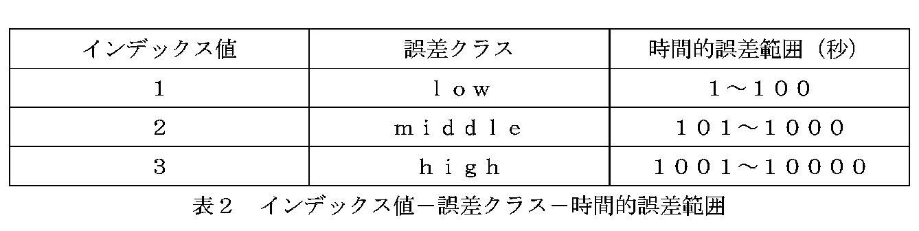
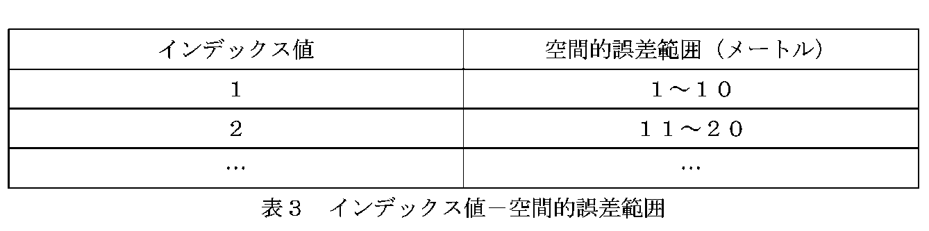
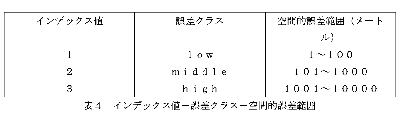
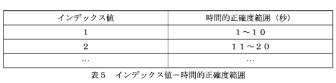

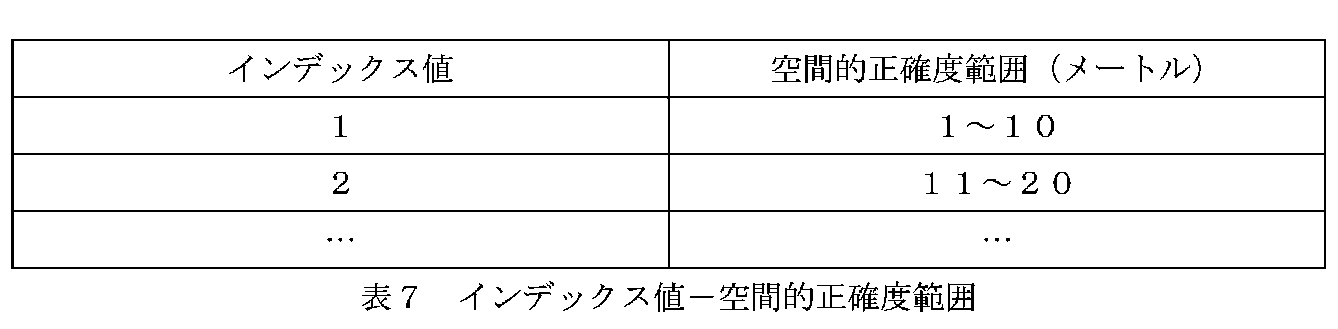
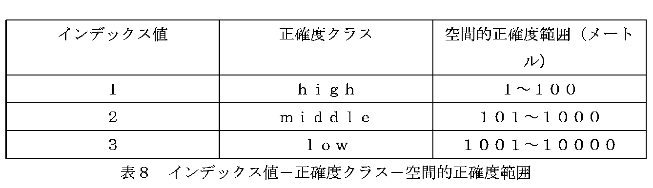
本章では、誤差情報が経路情報全体に対して適用される例を説明する。本例において、誤差情報は、端末装置10が時間的誤差及び/または空間的誤差を計算することによって生成される。経路情報報告情報が周期的に、または経路情報に変更があったことに応答して送信されてもよいことは上述した。いずれのケースでも、端末装置10は、複数のウェイポイントのそれぞれに対して誤差情報を生成する。
本章では、誤差情報がウェイポイントごとに適用される例を説明する。本例において、誤差情報は、経路情報と共に、端末装置10が時間的誤差及び/または空間的誤差を計算することによって生成される。経路情報報告情報が周期的に、または経路情報に変更があったことに応答して送信されてもよいことは上述した。いずれのケースでも、端末装置10は、複数のウェイポイントのそれぞれに対して誤差情報を生成する。
本章では、誤差情報を、端末装置10の能力情報(capability information)として送信する例を説明する。例えば、端末装置10ごとの過去に計算した時間的誤差が一定の範囲内にある場合、過去に計算した時間的誤差から導出された固定値が時間的誤差として端末装置10ごとに定義されてもよい。
次に、第2実施形態を説明する。第2実施形態では、基地局装置20が端末装置10に、経路情報についての誤差レベル及び/または正確度レベル、程度、または大きさを判定するための基準情報を送信する。以下、「レベル」、「程度」、及び「大きさ」は、交換可能に使用される。誤差に対する基準情報は、例えば、基地局装置20が端末装置10に対して要求する、要求時間的誤差及び/または要求空間的誤差を含んでもよい。要求時間的誤差及び要求空間的誤差は、要求誤差と総称する。要求時間的誤差は許容時間的誤差と交換可能に使用され、要求空間的誤差は許容空間的誤差と交換可能に使用され、許容時間的誤差及び許容空間的誤差、許容誤差と総称する。
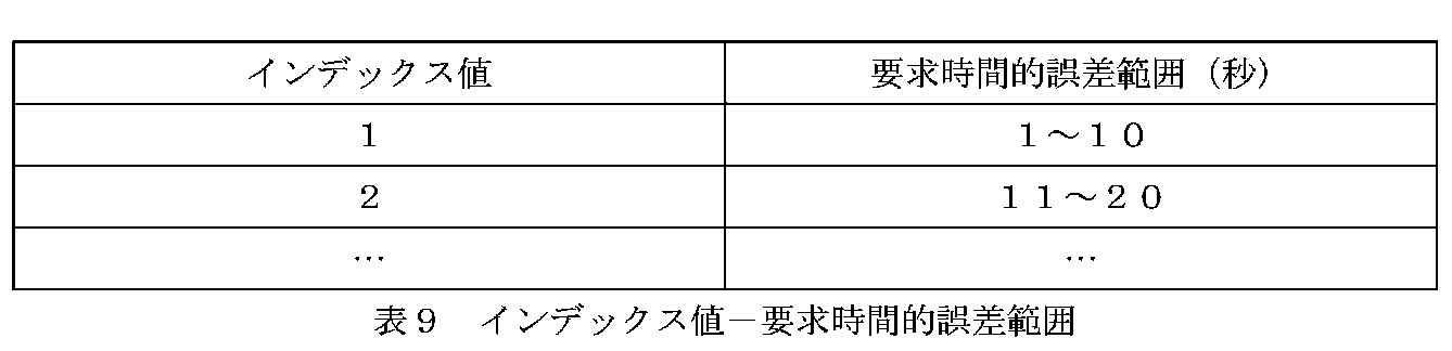

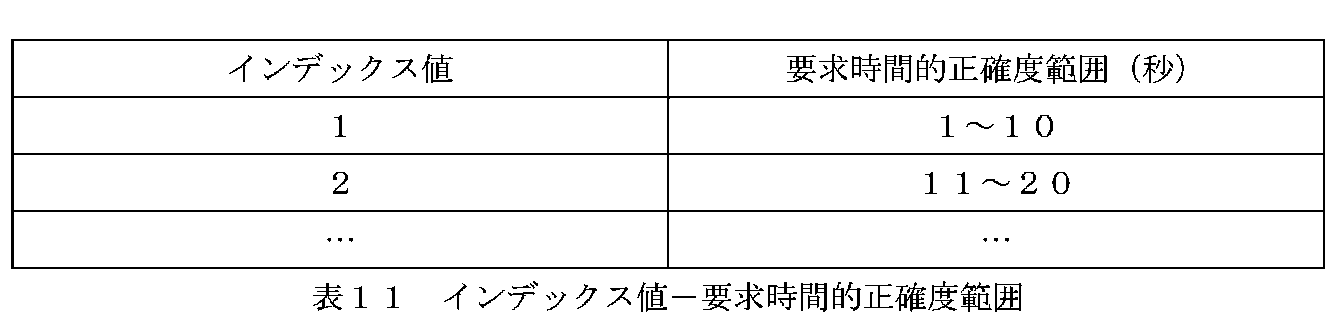
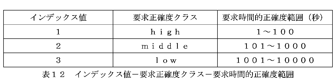
本開示は、上記実施形態に準拠して記述されたが、本開示は当該実施形態や構造に限定されるものではないと理解される。本開示は、様々な変形例や均等範囲内の変形をも包含する。上記実施形態に含まれる1つ以上の要素を含む他の組み合わせも、本開示の範疇や思想範囲に入るものである。
上記実施形態及び変形例の一部または全部は、以下の付記のようにも記載され得るが、以下の付記の内容には限定されない。以下では、複数の付記に従属する付記に対して、複数の付記に従属する付記が従属するという関係性が表現される。以下に表現される付記の従属関係の全てが上記実施形態に含まれる。
端末装置(10)であって、
基地局装置(20)によって使用される、前記端末装置の経路に関する経路情報を生成し、前記経路情報についての誤差情報を生成するように構成された制御部(110)と、
前記誤差情報を、基地局装置に送信するように構成された通信部(120)と、
を含む、端末装置。
前記誤差情報は、時間的誤差を含む、付記1に記載の端末装置。
前記時間的誤差は、前記端末装置が特定の地点に到達する時間に関する誤差を含む、付記2に記載の端末装置。
前記誤差情報は、空間的誤差を含む、付記1~3の何れか一項に記載の端末装置。
前記空間的誤差は、前記端末装置が予定経路を移動する位置に関する誤差を含む、付記4に記載の端末装置。
前記通信部は、前記基地局装置から、前記経路情報についての誤差レベルを判定するための基準情報を受信するように更に構成されている、付記1~5の何れか一項に記載の端末装置。
前記制御部は、前記基準情報に基づいて、前記誤差情報を生成するように更に構成されている、付記6に記載の端末装置。
前記制御部は、前記経路情報についての誤差レベルを判定するための予め定義された基準情報に基づいて、前記誤差情報を生成するように更に構成されている、付記1乃至5の何れか一項に記載の端末装置。
前記制御部は、前記端末装置が移動する経路全体に対して、前記誤差情報を生成するように更に構成されている、付記1~8の何れか一項に記載の端末装置。
前記制御部は、前記端末装置が経由する地点ごとに、前記誤差情報を生成するように更に構成されている、付記1~8の何れか一項に記載の端末装置。
前記通信部は、前記誤差情報を前記端末装置の能力情報として送信するように更に構成されている、付記1~10の何れか一項に記載の端末装置。
端末装置(10)であって、
基地局装置(20)によって使用される、前記端末装置の経路に関する経路情報を生成し、前記経路情報についての正確度情報を生成するように構成された制御部(110)と、
前記正確度情報を、基地局装置に送信するように構成された通信部(120)と、
を含む、端末装置。
前記正確度情報は、時間的正確度を含む、付記12に記載の端末装置。
前記時間的正確度は、前記端末装置が特定の地点に到達する時間に関する正確度を含む、付記13に記載の端末装置。
前記正確度情報は、空間的正確度を含む、付記12~14の何れか一項に記載の端末装置。
前記空間的正確度は、前記端末装置が予定経路を移動する位置に関する正確度を含む、付記15に記載の端末装置。
前記通信部は、前記基地局装置から、前記経路情報についての正確度レベルを判定するための基準情報を受信するように更に構成されている、付記12~16の何れか一項に記載の端末装置。
前記制御部は、前記基準情報に基づいて、前記正確度情報を生成するように更に構成されている、付記17に記載の端末装置。
前記制御部は、前記経路情報についての正確度レベルを判定するための予め定義された基準情報に基づいて、前記正確度情報を生成するように更に構成されている、付記12乃至16の何れか一項に記載の端末装置。
前記制御部は、前記端末装置が移動する経路全体に対して、前記正確度情報を生成するように更に構成されている、付記12~19の何れか一項に記載の端末装置。
前記制御部は、前記端末装置が経由する地点ごとに、前記正確度情報を生成するように更に構成されている、付記12~20の何れか一項に記載の端末装置。
前記通信部は、前記正確度情報を前記端末装置の能力情報として送信するように更に構成されている、付記12~21の何れか一項に記載の端末装置。
基地局装置(20)であって、
経路情報についての誤差情報を受信するように構成された通信部(220)であって、前記経路情報は、端末装置(10)の経路に関する情報である、通信部と、
前記誤差情報を使用するように構成された制御部(210)と、
を含む、基地局装置。
(付記24)
前記制御部は、前記経路情報についての誤差レベルを判定するための基準情報を生成するように更に構成され、
前記通信部は、前記基準情報を、端末装置に送信するように更に構成されている、
付記23に記載の基地局装置。
前記通信部は、前記誤差情報は、前記基準情報に基づいて生成されている、付記24に記載の基地局装置。
前記誤差情報は、時間的誤差を含む、付記25に記載の基地局装置。
前記時間的誤差は、前記端末装置が特定の地点に到達する時間に関する誤差を含む、付記26に記載の基地局装置。
前記誤差情報は、空間的誤差を含む、付記25~27の何れか一項に記載の基地局装置。
前記空間的誤差は、前記端末装置が予定経路を移動する位置に関する誤差を含む、付記28に記載の基地局装置。
前記基準情報は、基地局装置ごとに定義される、付記24~29の何れか一項に記載の基地局装置。
前記基準情報は、セルごとに定義される、付記24~29の何れか一項に記載の基地局装置。
前記基準情報は、セルグループごとに定義される、付記24~29の何れか一項に記載の基地局装置。
基地局装置(20)であって、
経路情報についての正確度情報を受信するように構成された通信部(220)であって、前記経路情報は、端末装置(10)の経路に関する情報である、通信部と、
前記正確度情報を使用するように構成された制御部(210)と、
を含む、基地局装置。
(付記34)
前記制御部は、前記経路情報についての正確度レベルを判定するための基準情報を生成するように更に構成され、
前記通信部は、前記基準情報を、端末装置に送信するように更に構成されている、
付記33に記載の基地局装置。
前記通信部は、前記端末装置から、前記正確度情報は、前記基準情報に基づいて生成されている、付記34に記載の基地局装置。
前記正確度情報は、時間的正確度を含む、付記35に記載の基地局装置。
前記時間的正確度は、前記端末装置が特定の地点に到達する時間に関する正確度を含む、付記36に記載の基地局装置。
前記正確度情報は、空間的正確度を含む、付記35~37の何れか一項に記載の基地局装置。
前記空間的正確度は、前記端末装置が予定経路を移動する位置に関する正確度を含む、付記38に記載の基地局装置。
前記基準情報は、基地局装置ごとに定義される、付記34~39の何れか一項に記載の基地局装置。
前記基準情報は、セルごとに定義される、付記34~39の何れか一項に記載の基地局装置。
前記基準情報は、セルグループごとに定義される、付記34~39の何れか一項に記載の基地局装置。
端末装置(10)によって実行される方法であって、
基地局装置(20)によって使用される、前記端末装置の経路に関する経路情報を生成し、前記経路情報についての誤差情報を生成することと、
前記誤差情報を、基地局装置に送信することと、
を含む、方法。
端末装置(10)によって実行される方法であって、
基地局装置(20)によって使用される、前記端末装置の経路に関する経路情報を生成し、前記経路情報についての正確度情報を生成することと、
前記正確度情報を、基地局装置に送信することと、
を含む、方法。
基地局装置(20)によって実行される方法であって、
経路情報についての誤差情報を受信することであって、前記経路情報は、端末装置(10)の経路に関する情報である、ことと
前記誤差情報を使用することと、
を含む、方法。
基地局装置(20)によって実行される方法であって、
経路情報についての正確度情報を受信することであって、前記経路情報は、端末装置(10)の経路に関する情報である、ことと
前記正確度情報を使用することと、
を含む、方法。
実行されるとき、端末装置(10)におけるプロセッサ(101)に、
基地局装置(20)によって使用される、前記端末装置の経路に関する経路情報を生成し、前記経路情報についての誤差情報を生成することと、
前記誤差情報を、基地局装置に送信することと、
を実行させる、プログラム。
実行されるとき、端末装置(10)におけるプロセッサ(101)に、
基地局装置(20)によって使用される、前記端末装置の経路に関する経路情報を生成し、前記経路情報についての正確度情報を生成することと、
前記正確度情報を、基地局装置に送信することと、
を実行させる、プログラム。
実行されるとき、基地局装置(20)におけるプロセッサ(201)に、
経路情報についての誤差情報を受信することであって、前記経路情報は、端末装置(10)の経路に関する情報である、ことと
前記誤差情報を使用することと、
を実行させる、プログラム。
実行されるとき、基地局装置(20)におけるプロセッサ(201)に、
経路情報についての正確度情報を受信することであって、前記経路情報は、端末装置(10)の経路に関する情報である、ことと
前記正確度情報を使用することと、
を実行させる、プログラム。
実行されるとき、端末装置(10)におけるプロセッサ(101)に、
基地局装置(20)によって使用される、前記端末装置の経路に関する経路情報を生成し、前記経路情報についての誤差情報を生成することと、
前記誤差情報を、基地局装置に送信することと、
を実行させる、プログラムを記憶したコンピュータ読取可能な非遷移的実体的記録媒体。
実行されるとき、端末装置(10)におけるプロセッサ(101)に、
基地局装置(20)によって使用される、前記端末装置の経路に関する経路情報を生成し、前記経路情報についての正確度情報を生成することと、
前記正確度情報を、基地局装置に送信することと、 を実行させる、プログラムを記憶したコンピュータ読取可能な非遷移的実体的記録媒体。
実行されるとき、基地局装置(20)におけるプロセッサ(201)に、
経路情報についての誤差情報を受信することであって、前記経路情報は、端末装置(10)の経路に関する情報である、ことと
前記誤差情報を使用することと、
を実行させる、プログラムを記憶したコンピュータ読取可能な非遷移的実体的記録媒体。
実行されるとき、基地局装置(20)におけるプロセッサ(201)に、
経路情報についての正確度情報を受信することであって、前記経路情報は、端末装置(10)の経路に関する情報である、ことと
前記正確度情報を使用することと、
を実行させる、プログラムを記憶したコンピュータ読取可能な非遷移的実体的記録媒体。
端末装置(10)及び基地局装置(20)を含む通信システムであって、
前記端末装置は、
前記端末装置の経路に関する経路情報を生成し、前記経路情報についての誤差情報を生成し、
前記誤差情報を、前記基地局装置に送信する
ように構成され、
前記基地局装置は、前記誤差情報を受信するように構成されている、
通信システム。
端末装置(10)及び基地局装置(20)を含む通信システムであって、
前記端末装置は、
前記端末装置の経路に関する経路情報を生成し、前記経路情報についての正確度情報を生成し、
前記正確度情報を、前記基地局装置に送信する
ように構成され、
前記基地局装置は、前記正確度情報を受信するように構成されている、
通信システム。
Claims (16)
- 端末装置(10)であって、
基地局装置(20)によって使用される、前記端末装置の経路に関する経路情報を生成し、前記経路情報についての誤差情報を生成するように構成された制御部(110)と、
前記誤差情報を、基地局装置に送信するように構成された通信部(120)と、
を含む、端末装置。 - 前記誤差情報は、時間的誤差を含む、請求項1に記載の端末装置。
- 前記時間的誤差は、前記端末装置が特定の地点に到達する時間に関する誤差を含む、請求項2に記載の端末装置。
- 前記誤差情報は、空間的誤差を含む、請求項1に記載の端末装置。
- 前記空間的誤差は、前記端末装置が予定経路を移動する位置に関する誤差を含む、請求項4に記載の端末装置。
- 前記通信部は、前記基地局装置から、前記経路情報についての誤差レベルを判定するための基準情報を受信するように更に構成されている、請求項1に記載の端末装置。
- 前記制御部は、前記基準情報に基づいて、前記誤差情報を生成するように更に構成されている、請求項6に記載の端末装置。
- 前記制御部は、前記経路情報についての誤差レベルを判定するための予め定義された基準情報に基づいて、前記誤差情報を生成するように更に構成されている、請求項1に記載の端末装置。
- 前記制御部は、前記端末装置が移動する経路全体に対して、前記誤差情報を生成するように更に構成されている、請求項1に記載の端末装置。
- 前記制御部は、前記端末装置が経由する地点ごとに、前記誤差情報を生成するように更に構成されている、請求項1に記載の端末装置。
- 前記通信部は、前記誤差情報を前記端末装置の能力情報として送信するように更に構成されている、請求項1に記載の端末装置。
- 基地局装置(20)であって、
経路情報についての誤差情報を受信するように構成された通信部(220)であって、前記経路情報は、端末装置(10)の経路に関する情報である、通信部と、
前記誤差情報を使用するように構成された制御部(210)と、
を含む、基地局装置。 - 前記制御部は、前記経路情報についての誤差レベルを判定するための基準情報を生成するように更に構成され、
前記通信部は、前記基準情報を、端末装置に送信するように更に構成されている、
請求項12に記載の基地局装置。 - 前記通信部は、前記誤差情報は、前記基準情報に基づいて生成されている、請求項13に記載の基地局装置。
- 端末装置(10)によって実行される方法であって、
基地局装置(20)によって使用される、前記端末装置の経路に関する経路情報を生成し、前記経路情報についての誤差情報を生成することと、
前記誤差情報を、基地局装置に送信することと、
を含む、方法。 - 基地局装置(20)によって実行される方法であって、
経路情報についての誤差情報を受信することであって、前記経路情報は、端末装置(10)の経路に関する情報である、ことと
前記誤差情報を使用することと、
を含む、方法。
Priority Applications (4)
| Application Number | Priority Date | Filing Date | Title |
|---|---|---|---|
| EP23885423.6A EP4615080A4 (en) | 2022-11-04 | 2023-10-02 | BASE STATION DEVICE, TERMINAL DEVICE AND PROCESS |
| CN202380075606.9A CN120113300A (zh) | 2022-11-04 | 2023-10-02 | 基站装置、终端装置及方法 |
| JP2024554322A JPWO2024095660A1 (ja) | 2022-11-04 | 2023-10-02 | |
| US19/193,276 US20250261267A1 (en) | 2022-11-04 | 2025-04-29 | Base station apparatus, terminal apparatus, and method |
Applications Claiming Priority (2)
| Application Number | Priority Date | Filing Date | Title |
|---|---|---|---|
| JP2022-177218 | 2022-11-04 | ||
| JP2022177218 | 2022-11-04 |
Related Child Applications (1)
| Application Number | Title | Priority Date | Filing Date |
|---|---|---|---|
| US19/193,276 Continuation US20250261267A1 (en) | 2022-11-04 | 2025-04-29 | Base station apparatus, terminal apparatus, and method |
Publications (1)
| Publication Number | Publication Date |
|---|---|
| WO2024095660A1 true WO2024095660A1 (ja) | 2024-05-10 |
Family
ID=90930339
Family Applications (1)
| Application Number | Title | Priority Date | Filing Date |
|---|---|---|---|
| PCT/JP2023/035953 Ceased WO2024095660A1 (ja) | 2022-11-04 | 2023-10-02 | 基地局装置、端末装置、及び方法 |
Country Status (5)
| Country | Link |
|---|---|
| US (1) | US20250261267A1 (ja) |
| EP (1) | EP4615080A4 (ja) |
| JP (1) | JPWO2024095660A1 (ja) |
| CN (1) | CN120113300A (ja) |
| WO (1) | WO2024095660A1 (ja) |
Citations (2)
| Publication number | Priority date | Publication date | Assignee | Title |
|---|---|---|---|---|
| US20210012665A1 (en) * | 2017-09-28 | 2021-01-14 | Lenovo (Beijing) Limited | METHOD AND APPARATUS FOR CONTROLLING THE OPERATION OF AERIAL UEs |
| JP2022177218A (ja) | 2021-12-08 | 2022-11-30 | ベイジン バイドゥ ネットコム サイエンス テクノロジー カンパニー リミテッド | 虚像生成モデルのトレーニング方法および虚像生成方法 |
Family Cites Families (1)
| Publication number | Priority date | Publication date | Assignee | Title |
|---|---|---|---|---|
| WO2019218114A1 (en) * | 2018-05-14 | 2019-11-21 | Lenovo (Beijing) Limited | Method and apparatus for flight path information reporting |
-
2023
- 2023-10-02 EP EP23885423.6A patent/EP4615080A4/en active Pending
- 2023-10-02 WO PCT/JP2023/035953 patent/WO2024095660A1/ja not_active Ceased
- 2023-10-02 JP JP2024554322A patent/JPWO2024095660A1/ja active Pending
- 2023-10-02 CN CN202380075606.9A patent/CN120113300A/zh active Pending
-
2025
- 2025-04-29 US US19/193,276 patent/US20250261267A1/en active Pending
Patent Citations (2)
| Publication number | Priority date | Publication date | Assignee | Title |
|---|---|---|---|---|
| US20210012665A1 (en) * | 2017-09-28 | 2021-01-14 | Lenovo (Beijing) Limited | METHOD AND APPARATUS FOR CONTROLLING THE OPERATION OF AERIAL UEs |
| JP2022177218A (ja) | 2021-12-08 | 2022-11-30 | ベイジン バイドゥ ネットコム サイエンス テクノロジー カンパニー リミテッド | 虚像生成モデルのトレーニング方法および虚像生成方法 |
Non-Patent Citations (3)
| Title |
|---|
| HUAWEI, HISILICON, CMCC, FRAUNHOFER, NOKIA, NOKIA SHANGHAI BELL, LENOVO, MOTOROLA MOBILITY, INTERDIGITAL, KDDI: "Discussion on flight path information", 3GPP TSG RAN WG2 MEETING #101BIS R2-1805125, 6 April 2018 (2018-04-06), XP051415864 * |
| JEDRZEJ STANCZAK, NOKIA, NOKIA SHANGHAI BELL: "On Flight Path Plan (FPP) for UAVs – Role, Content and Reporting Aspects", 3GPP TSG RAN WG2 MEETING #120 R2-2212269, 3 November 2022 (2022-11-03), XP052216353 * |
| See also references of EP4615080A4 |
Also Published As
| Publication number | Publication date |
|---|---|
| CN120113300A (zh) | 2025-06-06 |
| EP4615080A4 (en) | 2026-03-04 |
| JPWO2024095660A1 (ja) | 2024-05-10 |
| US20250261267A1 (en) | 2025-08-14 |
| EP4615080A1 (en) | 2025-09-10 |
Similar Documents
| Publication | Publication Date | Title |
|---|---|---|
| US20240396685A1 (en) | Method for user equipment in wireless communication system | |
| JP7604463B2 (ja) | 無線通信システムにおけるユーザ機器による方法 | |
| US12301498B2 (en) | Method and apparatus for performing sidelink-based positioning | |
| US20220229146A1 (en) | Prs transmission-based sidelink positioning of server terminal in nr v2x | |
| US20220326335A1 (en) | Sidelink tdoa-based positioning | |
| US12282086B2 (en) | Method and apparatus for efficient assistance data transfer in NR positioning | |
| CN115462135B (zh) | Nr v2x中的基于非独立免执照频带的定位方法和装置 | |
| US12474432B2 (en) | User equipment (UE) movement state estimation based on measurements for two or more sites in a wireless network | |
| KR102806428B1 (ko) | Das 기반 측위를 수행하는 방법 및 장치 | |
| CN116709371A (zh) | 基于测量间隙的sl prs传输的方法和设备 | |
| CN116669190A (zh) | 用于sl定位的测量间隙形成的方法和装置 | |
| JP7389294B1 (ja) | サーバ装置、制御方法及びプログラム | |
| WO2024095660A1 (ja) | 基地局装置、端末装置、及び方法 | |
| US20240129882A1 (en) | Positioning method and apparatus, device, and medium | |
| KR20260015827A (ko) | Soft v2x 에 기초한 위치 측정 방법 및 장치 | |
| US20240334386A1 (en) | Operation method related to positioning of sidelink remote ue in wireless communication system | |
| WO2024070217A1 (ja) | 基地局装置及び基地局装置の方法 | |
| WO2024070567A1 (ja) | 基地局装置、端末装置、及び方法 | |
| EP4668590A1 (en) | Method and device for wireless signal transmission/reception in wireless communication system | |
| WO2024212211A1 (en) | Devices and methods of communication | |
| US20260025785A1 (en) | Method and device for performing wireless communication on basis of prs | |
| EP4668641A1 (en) | Method and device for transmitting and receiving wireless signal in wireless communication system | |
| WO2025013847A1 (ja) | 通信装置、基地局、及び通信方法 | |
| WO2025013848A1 (ja) | 通信装置、基地局、及び通信方法 | |
| JP2026505445A (ja) | 無線通信システムにおいて無線信号の送受信方法および装置 |
Legal Events
| Date | Code | Title | Description |
|---|---|---|---|
| 121 | Ep: the epo has been informed by wipo that ep was designated in this application |
Ref document number: 23885423 Country of ref document: EP Kind code of ref document: A1 |
|
| WWE | Wipo information: entry into national phase |
Ref document number: 2024554322 Country of ref document: JP |
|
| WWE | Wipo information: entry into national phase |
Ref document number: 202380075606.9 Country of ref document: CN |
|
| WWE | Wipo information: entry into national phase |
Ref document number: 2023885423 Country of ref document: EP |
|
| NENP | Non-entry into the national phase |
Ref country code: DE |
|
| WWP | Wipo information: published in national office |
Ref document number: 202380075606.9 Country of ref document: CN |
|
| ENP | Entry into the national phase |
Ref document number: 2023885423 Country of ref document: EP Effective date: 20250604 |
|
| WWP | Wipo information: published in national office |
Ref document number: 2023885423 Country of ref document: EP |