WO2024095669A1 - スクロール圧縮機、及びそれを備える冷凍装置 - Google Patents
スクロール圧縮機、及びそれを備える冷凍装置 Download PDFInfo
- Publication number
- WO2024095669A1 WO2024095669A1 PCT/JP2023/036185 JP2023036185W WO2024095669A1 WO 2024095669 A1 WO2024095669 A1 WO 2024095669A1 JP 2023036185 W JP2023036185 W JP 2023036185W WO 2024095669 A1 WO2024095669 A1 WO 2024095669A1
- Authority
- WO
- WIPO (PCT)
- Prior art keywords
- space
- flow path
- partition member
- casing
- scroll compressor
- Prior art date
- Legal status (The legal status is an assumption and is not a legal conclusion. Google has not performed a legal analysis and makes no representation as to the accuracy of the status listed.)
- Ceased
Links
Images


Classifications
-
- F—MECHANICAL ENGINEERING; LIGHTING; HEATING; WEAPONS; BLASTING
- F04—POSITIVE - DISPLACEMENT MACHINES FOR LIQUIDS; PUMPS FOR LIQUIDS OR ELASTIC FLUIDS
- F04C—ROTARY-PISTON, OR OSCILLATING-PISTON, POSITIVE-DISPLACEMENT MACHINES FOR LIQUIDS; ROTARY-PISTON, OR OSCILLATING-PISTON, POSITIVE-DISPLACEMENT PUMPS
- F04C18/00—Rotary-piston pumps specially adapted for elastic fluids
- F04C18/02—Rotary-piston pumps specially adapted for elastic fluids of arcuate-engagement type, i.e. with circular translatory movement of co-operating members, each member having the same number of teeth or tooth-equivalents
- F04C18/0207—Rotary-piston pumps specially adapted for elastic fluids of arcuate-engagement type, i.e. with circular translatory movement of co-operating members, each member having the same number of teeth or tooth-equivalents both members having co-operating elements in spiral form
- F04C18/0215—Rotary-piston pumps specially adapted for elastic fluids of arcuate-engagement type, i.e. with circular translatory movement of co-operating members, each member having the same number of teeth or tooth-equivalents both members having co-operating elements in spiral form where only one member is moving
-
- F—MECHANICAL ENGINEERING; LIGHTING; HEATING; WEAPONS; BLASTING
- F04—POSITIVE - DISPLACEMENT MACHINES FOR LIQUIDS; PUMPS FOR LIQUIDS OR ELASTIC FLUIDS
- F04C—ROTARY-PISTON, OR OSCILLATING-PISTON, POSITIVE-DISPLACEMENT MACHINES FOR LIQUIDS; ROTARY-PISTON, OR OSCILLATING-PISTON, POSITIVE-DISPLACEMENT PUMPS
- F04C23/00—Combinations of two or more pumps, each being of rotary-piston or oscillating-piston type, specially adapted for elastic fluids; Pumping installations specially adapted for elastic fluids; Multi-stage pumps specially adapted for elastic fluids
- F04C23/008—Hermetic pumps
-
- F—MECHANICAL ENGINEERING; LIGHTING; HEATING; WEAPONS; BLASTING
- F04—POSITIVE - DISPLACEMENT MACHINES FOR LIQUIDS; PUMPS FOR LIQUIDS OR ELASTIC FLUIDS
- F04C—ROTARY-PISTON, OR OSCILLATING-PISTON, POSITIVE-DISPLACEMENT MACHINES FOR LIQUIDS; ROTARY-PISTON, OR OSCILLATING-PISTON, POSITIVE-DISPLACEMENT PUMPS
- F04C29/00—Component parts, details or accessories of pumps or pumping installations, not provided for in groups F04C18/00 - F04C28/00
- F04C29/02—Lubrication; Lubricant separation
- F04C29/026—Lubricant separation
-
- F—MECHANICAL ENGINEERING; LIGHTING; HEATING; WEAPONS; BLASTING
- F04—POSITIVE - DISPLACEMENT MACHINES FOR LIQUIDS; PUMPS FOR LIQUIDS OR ELASTIC FLUIDS
- F04C—ROTARY-PISTON, OR OSCILLATING-PISTON, POSITIVE-DISPLACEMENT MACHINES FOR LIQUIDS; ROTARY-PISTON, OR OSCILLATING-PISTON, POSITIVE-DISPLACEMENT PUMPS
- F04C2240/00—Components
- F04C2240/30—Casings or housings
Definitions
- This disclosure relates to scroll compressors, and in particular to scroll compressors that are less likely to cause unintended discharge of lubricating oil.
- Patent Document 1 JP Patent Publication No. 2017-025762 discloses a scroll compressor.
- Scroll compressors contain refrigerant and lubricating oil. After the compression process, the refrigerant is discharged from the scroll compressor. Meanwhile, the lubricating oil is expected to remain inside the scroll compressor. However, because lubricating oil is compatible with the refrigerant, a phenomenon known as "oil rise" can occur in which the lubricating oil is discharged outside the scroll compressor along with the refrigerant.
- the scroll compressor according to the first aspect includes a casing, a partition member, a compression element, a first flow path, and a second flow path.
- the casing has an internal space in which lubricating oil is present.
- the casing is cylindrical.
- the partition member is fixed to the casing to divide the internal space into a first space and a second space.
- the compression element has a fixed scroll and a movable scroll. The movable scroll moves relative to the fixed scroll.
- the compression element discharges refrigerant into the first space.
- the first flow path is provided in the partition member.
- the first flow path passes the refrigerant from the first space to the second space.
- the second flow path is provided in the partition member so as to be spaced apart from the first flow path.
- the second flow path is configured to guide the lubricating oil to the second space.
- the second flow path has a narrow portion.
- the narrow portion has the narrowest flow path area.
- the ratio of the hydraulic diameter of the narrow portion to the length of the narrow portion in the axial direction of the casing is 0.01 or more and 0.07 or less.
- a second flow path dedicated to lubricating oil is provided in the partition member, separate from the first flow path for the refrigerant.
- the narrow portion of the second flow path has a shape defined by 0.01 ⁇ D/L ⁇ 0.07, so the second flow path allows the lubricating oil, which is a liquid, to pass through while offering resistance to the refrigerant, which is a gas. This reduces the chances of the refrigerant and the lubricating oil mixing, thereby suppressing oil rise.
- the scroll compressor according to the second aspect comprises a casing, a partition member, a compression element, a first flow path, and a second flow path.
- the casing has an internal space in which lubricating oil is present.
- the casing is cylindrical.
- the partition member is fixed to the casing to divide the internal space into a first space and a second space.
- the compression element has a fixed scroll, a movable scroll, and a discharge hole.
- the movable scroll moves relative to the fixed scroll.
- the discharge hole faces the first space.
- the first flow path is provided in the partition member.
- the first flow path connects the first space and the second space.
- the first flow path has a radial dimension of the partition member of 2 mm or more.
- the second flow path is provided in the partition member so as to be spaced apart from the first flow path.
- the second flow path has a radial dimension of the partition member of 2 mm or more.
- the second flow path has a narrow portion.
- the narrow portion has the narrowest flow path area.
- the ratio of the hydraulic diameter of the narrow portion to the length of the narrow portion in the axial direction of the casing is 0.01 or more and 0.07 or less.
- a second flow path dedicated to lubricating oil is provided in the partition member, separate from the first flow path for the refrigerant.
- the narrow portion of the second flow path has a shape defined by 0.01 ⁇ D/L ⁇ 0.07, so the second flow path allows the lubricating oil, which is a liquid, to pass through while offering resistance to the refrigerant, which is a gas. This reduces the chances of the refrigerant and the lubricating oil mixing, thereby suppressing oil rise.
- the scroll compressor according to the third aspect is the scroll compressor according to the first or second aspect, in which the ratio of the hydraulic diameter of the narrow portion to the length of the narrow portion is 0.03 or more and 0.06 or less.
- the narrow portion of the second flow path has a shape that satisfies 0.03 ⁇ D/L ⁇ 0.06, so the second flow path presents further resistance to the gaseous refrigerant. Therefore, oil rise is more effectively suppressed.
- the scroll compressor according to the fourth aspect is a scroll compressor according to any one of the first to third aspects, in which the length of the narrow portion is 5 mm or more and 80 mm or less.
- the narrow portion of the second flow path has a length of 5 mm or more and 80 mm or less. Therefore, the length that creates resistance to the refrigerant is ensured, and oil rise is suppressed.
- the scroll compressor according to the fifth aspect is a scroll compressor according to any one of the first to fourth aspects, in which the partition member is a separate part from the compression element.
- the member that separates the first space from the second space does not compress the refrigerant. Therefore, the design of the narrow portion is less subject to the design constraints of the compression element.
- the scroll compressor according to the sixth aspect is a scroll compressor according to any one of the first to fifth aspects, in which the partition member is a fixed scroll.
- the fixed scroll also serves to separate the first space from the second space. This allows the number of parts in the scroll compressor to be reduced.
- the scroll compressor according to the seventh aspect is a scroll compressor according to any one of the first to sixth aspects, in which the cross-sectional shape of the narrow portion is a rectangle having a first side extending in the radial direction of the casing and a second side extending in the circumferential direction of the casing by a length not greater than three times that of the first side.
- the length of the second side is three times or less than the length of the first side. Therefore, since the lengths of the second side and the first side are close, the narrow portion does not need to have an extremely flat structure, and manufacturing processing is easy.
- the scroll compressor according to the eighth aspect is a scroll compressor according to any one of the first to sixth aspects, in which the cross-sectional shape of the narrow portion is a triangle having a height extending in the radial direction of the casing and a base extending in the circumferential direction of the casing a length that is three times or less than the height.
- the length of the base is three times or less the height. Therefore, since the length of the base and the height are close, the narrow portion does not need to have an extremely flat structure, making it easy to process for manufacturing.
- the scroll compressor according to the ninth aspect is a scroll compressor according to any one of the first to sixth aspects, in which the cross-sectional shape of the narrow portion is semicircular or semielliptical.
- the shape of the narrow portion is semicircular or semielliptical. Therefore, processing to form the narrow portion is easy.
- the scroll compressor according to the tenth aspect is a scroll compressor according to any one of the first to ninth aspects, in which the partition member has a step portion.
- the step portion receives the lubricating oil moving from the first space.
- the second flow path is in communication with the step portion.
- the step portion faces the first space. Therefore, the step portion collects the lubricating oil present in the first space and guides the lubricating oil to the second flow path, further reducing the chance of the refrigerant and the lubricating oil mixing.
- the refrigeration device includes a scroll compressor according to any one of the first to tenth aspects.
- the scroll compressor of the refrigeration system has a second flow path dedicated to lubricating oil, separate from the first flow path for the refrigerant.
- the narrow portion of the second flow path has a shape defined by 0.01 ⁇ D/L ⁇ 0.07, so the second flow path allows the lubricating oil, which is a liquid, to pass through while offering resistance to the refrigerant, which is a gas. This reduces the chances of the refrigerant and lubricating oil mixing, suppressing oil rise.
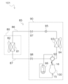
- FIG. 1 is a refrigerant circuit diagram showing a configuration of a refrigeration device 101.
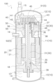
- 1 is a cross-sectional view showing a scroll compressor 100 according to a first embodiment.
- 1 is a schematic diagram of a main part of a scroll compressor 100 according to a first embodiment.
- FIG. 2 is a perspective view showing a partition member 50 according to the first embodiment.
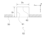
- 4 is a schematic diagram showing a cross section of a second flow path 52 according to the first embodiment.
- FIG. FIG. 4 is a schematic diagram showing the movement of a refrigerant.
- FIG. 1A is a schematic diagram showing a cross section of a second flow path 52 according to a first modified example 1A of the first embodiment.
- FIG. 10 is a schematic diagram showing a cross section of a second flow path 52 according to a second modified example 1B of the first embodiment.
- FIG. FIG. 11 is a schematic diagram of a main part of a scroll compressor 100 according to a third modified example 1C of the first embodiment.
- FIG. 6 is a schematic diagram of a main part of a scroll compressor 100 according to a second embodiment.
- FIG. 11 is a perspective view showing a partition member 50 according to a second embodiment.
- FIG. 4 is a cross-sectional view of a scroll compressor 100 according to a second embodiment.
- First Embodiment 1 shows the configuration of a refrigeration device 101 according to the first embodiment.
- the refrigeration device 101 has a heat source unit 90, a utilization unit 80, and a communication pipe group 85.
- the heat source unit 90 functions as a heat source or cold source for the refrigerant.
- the heat source unit 90 has a scroll compressor 100, a four-way switching valve 92, a heat source heat exchanger 93, a heat source fan 94, an expansion valve 95, an accumulator 96, a liquid shutoff valve 97, and a gas shutoff valve 98.
- the utilization unit 80 provides the heat or cold received from the refrigerant to the user.
- the utilization unit 80 has a utilization heat exchanger 81 and a utilization fan 82.
- the interconnecting piping group 85 connects the heat source unit 90 and the utilization unit 80.
- the interconnecting piping group 85 has a liquid pipe 86 and a gas pipe 87.
- the liquid pipe 86 connects the liquid shutoff valve 97 and the utilization heat exchanger 81.
- the gas pipe 87 connects the gas shutoff valve 98 and the utilization heat exchanger 81.
- the scroll compressor 100 generates high-pressure gas refrigerant by compressing low-pressure gas refrigerant.
- the refrigeration device 101 operates in a cold heat utilization mode.
- the utilization heat exchanger 81 functions as an evaporator or heat absorber, and provides cold heat to the user.
- the refrigeration device 101 operates in a hot heat utilization mode.
- the utilization heat exchanger 81 functions as a condenser or heat radiator, and provides hot heat to the user.
- FIG. 2 shows the configuration of the scroll compressor 100.
- the scroll compressor 100 has a casing 10, a motor 20, a crankshaft 30, and a compression element 40.
- the casing 10 has a body portion 11, an upper portion 12, and a lower portion 13 that are hermetically joined together.
- the internal space S exists within the casing 10.
- the internal space S contains the scroll compressor 100 components, a refrigerant, and lubricating oil LO.
- a suction pipe 15 is attached to the upper portion 12 for drawing in low-pressure gas refrigerant.
- a discharge pipe 16 is attached to the body portion 11 for discharging high-pressure gas refrigerant.
- a partition member 50 and a support member 18 are also attached to the body portion 11.
- the partition member 50 divides the internal space S into a first space S1 and a second space S2.
- the partition member 50 also supports the compression element 40 and the upper portion of the crankshaft 30.
- the support member 18 supports the lower portion of the crankshaft 30.
- An oil reservoir 14 for storing lubricating oil LO is provided near the lower portion 13.
- the motor 20 generates power for driving the compression element 40 by utilizing electric power supplied from outside the scroll compressor 100.
- the motor 20 has a stator 21 and a rotor 22.
- the stator 21 is fixed to the body 11.
- the rotor 22 is disposed in a cavity in the center of the stator 21 and is supported rotatably.
- crankshaft 30 transmits the power generated by the motor 20 to the compression element 40.
- the crankshaft 30 has a main shaft portion 31 and an eccentric portion 32 that is eccentric from the main shaft portion 31. A part of the main shaft portion 31 passes through a cavity in the center of the rotor 22 and is fixed to the rotor 22.
- a main passage 35 is provided inside the crankshaft 30 to draw up the lubricating oil LO from the oil reservoir 14.
- the main passage 35 is connected to a number of branch passages 36 extending radially of the crankshaft 30.
- the branch passages 36 are for supplying the lubricating oil LO to the side of the main shaft portion 31 or the eccentric portion 32.
- the branch passages 36 guide the lubricating oil LO to the first bearing 37, the second bearing 38, and the third bearing 39.
- the compression element 40 generates high-pressure gas refrigerant by compressing a low-pressure gas refrigerant using power transmitted by the crankshaft 30.
- the compression element 40 has a fixed scroll 41 and a movable scroll 42.
- the fixed scroll 41 is supported by a partition member 50.
- the movable scroll 42 has a boss 46.
- the eccentric portion 32 of the crankshaft 30 is fitted into a recess of the boss 46.
- the rotation of the crankshaft 30 is transmitted to the boss 46 via the first bearing 37, whereby the movable scroll 42 revolves relative to the fixed scroll 41.
- a number of compression chambers 43 are formed between the fixed scroll 41 and the movable scroll 42. As the crankshaft 30 revolves the movable scroll 42, the volume of the compression chambers 43 varies, thereby compressing the refrigerant. The generated high-pressure gas refrigerant is discharged from a discharge hole 45 provided in the fixed scroll 41 into the first space S1.
- FIG. 3 shows the partition member 50 and its surrounding structure.
- the casing 10 has a cylindrical shape extending in the axial direction a.
- the cross section of the body 11 of the casing 10 is a circle spaced apart from the center in the radial direction r and extending along the circumferential direction c perpendicular to the radial direction r.
- the inner circumference Ci of the body 11 of the casing 10 is shown.
- the internal space S of the casing 10 is divided into a first space S1 and a second space S2 by the partition member 50.
- the partition member 50 supports the compression element 40.
- the partition member 50 has a fixing surface 55.
- the fixing surface 55 is fixed to the body of the casing 10.
- the diameter of the partition member 50 is, for example, 140 mm or more and 250 mm.
- the inner circumference Ci of the body 11 of the casing 10 is, for example, 520 mm or more and 800 mm.
- the partition member 50 is a separate part from the compression element 40.
- FIG. 4 shows the detailed structure of the partition member 50.
- the partition member 50 has a peripheral edge 54.
- the peripheral edge 54 has a fixing surface 55 and a step portion 57.
- the fixing surface 55 is provided on a portion of the partition member 50 that bulges outward in the radial direction r of the body portion 11 of the casing 10, in other words, in the radial direction r of the partition member 50.
- the fixed surface 55 is provided with one first flow path 51 and one second flow path 52.
- the second flow path 52 is spaced apart from the first flow path 51.
- the first flow path 51 is for passing the refrigerant from the first space S1 to the second space S2.
- the second flow path 52 is for guiding the lubricating oil LO to the second space S2.
- the second flow path 52 has a narrow section 59.
- the narrow section 59 is the portion of the second flow path 52 that has the narrowest flow path area.
- the second flow path 52 has a constant flow path area, so the narrow section 59 is the entire second flow path 52.
- the narrow portion 59 has a length L and a hydraulic diameter D.
- the length L is the dimension of the narrow portion 59 in the axial direction a of the casing 10.
- the hydraulic diameter D is the diameter of the circular cross-sectional area of the narrow portion 59, whose cross-sectional area is not circular, when converted into a flow path having a circular cross-sectional area. Methods for calculating hydraulic radius are well known to those skilled in the art.
- the length L is, for example, 5 mm or more and 80 mm or less.
- the ratio D/L of the hydraulic diameter D to the length L is set, for example, to 0.01 or more and 0.07 or less. Preferably, the ratio D/L is set, for example, to 0.03 or more and 0.06 or less.
- the dimension Er of the first flow passage 51 in the radial direction r of the body 11 of the casing 10, in other words, in the radial direction r of the partition member 50, is, for example, 2 mm or more and 20 mm or less.
- the step portion 57 is provided above the fixed surface 55 on the periphery 54 of the partition member 50.
- the step portion 57 faces the first space S1.
- the step portion 57 is retracted by a retraction width W inward in the radial direction r from the fixed surface 55.
- the retraction width W is 3 mm or less, and preferably 2 mm or less.
- the second flow path 52 is in communication with the step portion 57.
- the partition member 50 further has a storage section 56.
- the storage section 56 stores the boss 46 of the movable scroll 42.
- the storage section 56 also functions as a temporary storage section for collecting the lubricating oil LO that has finished lubricating the compression element 40.
- Figure 5 shows the cross-sectional shape of narrow portion 59.
- the cross-section of narrow portion 59 is a rectangle having a first side 61 extending in the radial direction r of casing 10 and a second side 62 extending in the circumferential direction c.
- the length Dc of second side 62 is three times or less the length Dr of first side 61.
- the length Dc of second side 62 is one time or more the length Dr of first side 61.
- FIG. 6 shows the movement of the refrigerant.
- the movement of the refrigerant is represented by the thick solid arrows.
- the refrigerant compressed to a high pressure state, is discharged from the discharge hole 45 into the first space S1.
- the refrigerant collides with the upper part 12 of the casing 10 that surrounds the first space S1, or moves along the inner surface of the upper part 12.
- the refrigerant then passes through the first flow path 51 and moves to the second space S2. Note that the refrigerant does not pass through the second flow path 52 very much due to the resistance caused by the small dimensions Dr and Dc, in other words, the small hydraulic diameter D.
- the refrigerant that fills the first space S1 contains a certain amount of lubricating oil LO. As the refrigerant moves as described above, a portion of the lubricating oil LO passes through the first flow path 51 and moves to the second space S2.
- Figure 7 shows other movements of the lubricant LO.
- the movement of the lubricant LO is represented by thick dashed arrows.
- a certain amount of lubricating oil LO is separated from the refrigerant and becomes oil droplets that adhere to the inner surface of the upper part 12.
- the lubricating oil LO in the form of oil droplets then falls downward along the inner surface of the upper part 12 due to the action of gravity.
- the oil droplets of the lubricating oil LO then collect at the step portion 57.
- the lubricating oil LO moves along the inner circumference Ci of the body part 11 of the casing 10 and the step portion 57.
- the lubricating oil LO in a liquid state then passes through the first flow path 51 or the second flow path 52 due to the action of gravity and moves to the second space S2.
- the lubricating oil LO then falls into the oil reservoir 14.
- a second flow path 52 exclusively for the lubricating oil LO is provided in the partition member 50, separate from the first flow path 51 for the refrigerant.
- the narrowed portion 59 of the second flow path 52 has a shape defined by 0.01 ⁇ D/L ⁇ 0.07 or 0.03 ⁇ D/L ⁇ 0.06, so that the second flow path 52 passes the lubricating oil LO, which is a liquid, while exhibiting resistance to the refrigerant, which is a gas. This reduces the chance of the refrigerant and the lubricating oil LO being mixed, thereby suppressing oil rising.
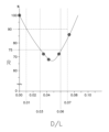
- Figure 8 is a graph showing the effect of suppressing oil rise brought about by the second flow path 52.
- the horizontal axis shows the ratio D/L of the hydraulic diameter D of the narrow portion 59 to the length L of the narrow portion 59.
- the vertical axis shows the oil rise rate R (%), which is expressed as a percentage relative to the intercept of the vertical axis of 100%. The larger the oil rise rate R, the greater the amount of lubricating oil LO discharged from the scroll compressor 100.
- the narrow portion 59 of the second flow passage 52 has a length L of 5 mm or more and 80 mm or less. Therefore, the length L that generates resistance to the refrigerant is ensured, and oil rise is suppressed.
- the partition member 50 which separates the first space S1 from the second space S2, does not compress the refrigerant. Therefore, the design of the narrow portion 59 is not easily restricted by the design of the compression element 40.
- the length Dc of the second side 62 is three times or less the length Dr of the first side 61. Therefore, since the lengths of the second side 62 and the first side 61 are close to each other, the narrow portion 59 does not need to have an extremely flat structure, and the manufacturing process is easy.
- the step portion 57 faces the first space S1. Therefore, the step portion 57 collects the lubricating oil LO present in the first space S1 and guides the lubricating oil LO to the second flow path 52, further reducing the chance of the refrigerant and the lubricating oil LO being mixed together.
- the cross section of the narrow portion 59 is rectangular.
- the cross section of the narrow portion 59 may be triangular.
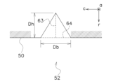
- Figure 9 shows a cross section of the narrow portion 59 according to the first modified example 1A of the first embodiment.
- the shape of the cross section is a triangle having a height 63 extending in the radial direction r of the casing 10 and a base 64 extending in the circumferential direction c of the casing 10.
- the dimension Ds of the base 64 is three times or less the dimension Dh of the height 63.
- the dimension Ds of the base 64 is one or more times the dimension Dh of the height 63.
- the dimension Db of the base 64 is three times or less the dimension Dh of the height 63. Since the two dimensions are close to each other, the narrow portion 59 does not need to have an extremely flat structure, and it is easy to process for manufacturing.
- the cross section of the narrow portion 59 is rectangular.
- the cross section of the narrow portion 59 may be semi-elliptical.
- FIG. 10 shows a cross section of the narrow portion 59 according to the second modified example 1B of the first embodiment.
- the shape of the cross section is a semi-ellipse having a first shaft radius 65 extending in the radial direction r of the casing 10 and a second shaft radius 66 extending in the circumferential direction c.
- the dimension Dy of the second shaft radius 66 is less than or equal to three times the dimension Dx of the first shaft radius 65.
- the dimension Dy of the second shaft radius 66 is greater than or equal to one time the dimension Dx of the first shaft radius 65.
- the cross-sectional shape may be semicircular such that the dimension Dy of the second shaft diameter 66 is exactly twice the dimension Dx of the first shaft radius 65.
- the shape of the narrow portion 59 is semicircular or semielliptical. Therefore, processing to form the narrow portion 59 is easy.
- the partition member 50 is a separate part from the compression element 40.
- the partition member 50 may belong to the compression element 40.
- FIG. 11 shows a scroll compressor 100 according to a third modified example 1C of the first embodiment.
- the compression element 40 of the scroll compressor 100 has a fixed scroll 41.
- the fixed scroll 41 also functions as a partition member 50, and divides the internal space S into a first space S1 and a second space S2.
- the fixed scroll 41 has a fixed surface 55.
- the fixed surface 55 is fixed to the body of the casing 10.
- the fixed surface 55 is provided with one first flow path 51 and one second flow path 52.
- the second flow path 52 is spaced apart from the first flow path 51.
- the first flow path 51 is for passing the refrigerant from the first space S1 to the second space S2.
- the second flow path 52 is for guiding the lubricating oil LO to the second space S2.
- the structure of the narrow portion 59 of the second flow path 52 is the same as in the first embodiment.
- the fixed scroll 41 also serves to separate the first space S1 from the second space S2. This allows the number of parts in the scroll compressor 100 to be reduced.
- one first flow passage 51 and one second flow passage 52 are provided on the fixing surface 55 of the partition member 50.
- a plurality of first flow passages 51 or a plurality of second flow passages 52 may be provided on the partition member 50.
- providing a plurality of second flow passages 52 promotes the movement of the lubricating oil LO from the first space S1 to the second space S2, thereby effectively suppressing oil rise.
- Second Embodiment 12 shows the configuration of a scroll compressor 100 according to a second embodiment.
- the structure of the second flow passage 52 is different from that in the first embodiment.
- the scroll compressor 100 has a partition member 50. As shown in FIG. 13, the periphery 54 of the partition member 50 has a fixing surface 55 and a step portion 57, similar to the first embodiment.
- the fixing surface 55 has a first flow path 51 and a second flow path 52.
- the second flow path 52 is for guiding the lubricating oil LO to the second space S2.
- the second flow path is provided by utilizing the welded portion between the partition member 50 and the casing 10.
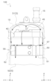
- FIG 14 shows the welding points between the partition member 50 and the casing 10.
- the partition member 50 has multiple accommodation holes 71. Each accommodation hole 71 is for accommodating a fixing member 72.
- the fixing members 72 are pressed into the accommodation holes 71 and fixed.
- the fixing members 72 are made of a material to which molten metal can be easily fixed.
- the molten metal comes into contact with the fixing members 72.
- the molten metal then solidifies to become a welded portion 73 that is fixed to the fixing members 72.
- the second flow passage 52 and the narrow portion 59 which is a part of the second flow passage 52, are formed by utilizing the welded portions. Therefore, the existing structure can be reused, and no major design changes are required.
Landscapes
- Engineering & Computer Science (AREA)
- Mechanical Engineering (AREA)
- General Engineering & Computer Science (AREA)
- Rotary Pumps (AREA)
- Applications Or Details Of Rotary Compressors (AREA)
Abstract
Description
(1)冷凍装置101の構成
図1は第1実施形態に係る冷凍装置101の構成を示す。冷凍装置101は、熱源ユニット90、利用ユニット80、及び連絡配管群85を有する。
図2はスクロール圧縮機100の構成を示す。スクロール圧縮機100は、ケーシング10、モータ20、クランク軸30、圧縮要素40を有する。
ケーシング10は、互いに気密的に接合された胴部11、上部12、及び下部13を有する。
モータ20は、スクロール圧縮機100の外部から供給される電力を利用して、圧縮要素40を駆動するための動力を生成する。モータ20は、ステータ21及びロータ22を有する。ステータ21は胴部11に固定されている。ロータ22は、ステータ21の中心部の空洞に配置され、回転可能に支持されている。
クランク軸30は、モータ20が生成した動力を圧縮要素40へ伝達する。クランク軸30は、主軸部31と、主軸部31より偏心した偏心部32とを有する。主軸部31の一部はロータ22の中心部の空洞を通過しており、ロータ22と固定されている。
圧縮要素40は、クランク軸30によって伝達された動力を利用して、低圧ガス冷媒を圧縮することによって高圧ガス冷媒を生成する。圧縮要素40は、固定スクロール41と可動スクロール42を有する。固定スクロール41は、仕切部材50に支持されている。可動スクロール42は、ボス46を有する。ボス46の凹部には、クランク軸30の偏心部32がはめ込まれている。クランク軸30の回転は、第1軸受37を介してボス46に伝達され、それによって可動スクロール42が固定スクロール41に対して公転する。
図3は、仕切部材50とその周辺の構造を示す。ケーシング10は、軸方向aに延びる円筒形状を有する。ケーシング10の胴部11の断面は、中心から径方向rに離間しており、径方向rと直交する周方向cに沿う円形である。本図には、ケーシング10の胴部11の内周Ciが示されている。
図6は、冷媒の移動を示す。冷媒の移動は、太い実線の矢印で表されている。
(5-1)
冷媒用の第1流路51とは別に、潤滑油LO専用の第2流路52が仕切部材50に設けられる。第2流路52の狭小部59は0.01≦D/L≦0.07、又は、0.03≦D/L≦0.06で規定される形状を有するので、第2流路52は液体である潤滑油LOを通過させるとともに、気体である冷媒に対しては抵抗を示す。したがって、冷媒と潤滑油LOが混合される機会が低減するので、油上がりが抑制される。
第2流路52の狭小部59は、5mm以上かつ80mm以下の長さLを有する。したがって、冷媒に対する抵抗を生み出す長さLが確保されるので、油上がりが抑制される。
第1空間S1と第2空間S2の隔離を担う仕切部材50は、冷媒の圧縮を行わない。したがって、狭小部59の設計が圧縮要素40の設計の制約を受けにくい。
第2辺62の長さDcは第1辺61の長さDrの3倍以下である。したがって、第2辺62と第1辺61の長さが近いので、狭小部59は極端な扁平構造を有する必要がなく、製造のための加工が容易である。
段差部57は第1空間S1に臨んでいる。したがって、段差部57は第1空間S1に存在する潤滑油LOを集め、その潤滑油LOを第2流路52へ案内するので、冷媒と潤滑油LOが混合される機会がさらに低減する。
以下に、上述の第1実施形態の変形例について説明する。複数の変形例を組み合わせてもよい。
第1実施形態において、狭小部59の断面は四角形である。これに代えて、狭小部59の断面は三角形であってもよい。
第1実施形態において、狭小部59の断面は四角形である。これに代えて、狭小部59の断面は半楕円形であってもよい。
第1実施形態において、仕切部材50は、圧縮要素40とは別体の部品である。これに代えて、仕切部材50は圧縮要素40に属してもよい。
第1実施形態において、仕切部材50の固定面55には、1つの第1流路51と、1つの第2流路52が設けられる。これに代えて、複数の第1流路51、又は、複数の第2流路52が仕切部材50に設けられてもよい。とりわけ、複数の第2流路52を設けることは、潤滑油LOの第1空間S1から第2空間S2への移動を促進するので、油上がりを効果的に抑制する。
(1)構成
図12は、第2実施形態に係るスクロール圧縮機100の構成を示す。第2実施形態においては、第2流路52の構造が第1実施形態とは異なっている。
この構成によれば、第2流路52及びその一部である狭小部59は、溶接箇所を利用して形成されている。したがって、既存の構造を流用できるので、大がかりな設計変更を要しない。
上述の第1実施形態の変形例1A~1Dの少なくとも一部を、第2実施形態に適用してもよい。
以上、本開示の実施形態を説明したが、請求の範囲に記載された本開示の趣旨及び範囲から逸脱することなく、形態や詳細の多様な変更が可能なことが理解されるであろう。
11 :胴部
14 :油溜まり
18 :支持部材
20 :モータ
30 :クランク軸
40 :圧縮要素
41 :固定スクロール(仕切部材)
42 :可動スクロール
50 :仕切部材(圧縮要素とは別体の部品)
51 :第1流路
52 :第2流路
54 :周縁
55 :固定面
57 :段差部
59 :狭小部
61 :第1辺
62 :第2辺
63 :高さ
64 :底辺
65 :第1軸半径
66 :第2軸直径
71 :収容孔
72 :固定部材
73 :溶接部
80 :利用ユニット
90 :熱源ユニット
100 :スクロール圧縮機
101 :冷凍装置
D :狭小部の水力直径
D/L :長さに対する水力直径の比率
L :軸方向における狭小部の長さ
LO :潤滑油
S :内部空間
S1 :第1空間
S2 :第2空間
R :油上がり率
a :ケーシングの軸方向
c :ケーシングの周方向
r :ケーシングの径方向
Claims (11)
- 潤滑油(LO)が存在する内部空間(S)を有する円筒形のケーシング(10)と、
前記ケーシングに固定されることによって、前記内部空間を第1空間(S1)及び第2空間(S2)に分割する仕切部材(50、41)と、
固定スクロール(41)及び前記固定スクロールに対して移動する可動スクロール(42)を有し、前記第1空間へ冷媒を吐出する圧縮要素(40)と、
前記仕切部材に設けられ、前記第1空間から前記第2空間へ前記冷媒を通過させる第1流路(51)と、
前記第1流路から離間するように前記仕切部材に設けられ、前記潤滑油を前記第2空間へ案内するように構成され、最も狭い流路面積を有する狭小部(59)を有し、前記ケーシングの軸方向における前記狭小部の長さ(L)に対する前記狭小部の水力直径(D)の比率(D/L)が0.01以上かつ0.07以下である、第2流路(52)と、
を備える、スクロール圧縮機(100)。 - 潤滑油(LO)が存在する内部空間(S)を有する円筒形のケーシング(10)と、
前記ケーシングに固定されることによって、前記内部空間を第1空間(S1)及び第2空間(S2)に分割する仕切部材(50、41)と、
固定スクロール(41)、前記固定スクロールに対して移動する可動スクロール(42)、及び前記第1空間に面する吐出孔(45)を有する圧縮要素(40)と、
前記仕切部材に設けられ、前記第1空間と前記第2空間とを接続する第1流路(51)であって、前記仕切部材の径方向の寸法(Er)が2mm以上である第1流路(51)と、
前記第1流路から離間するように前記仕切部材に設けられ、前記第1空間と前記第2空間とを接続する第2流路(52)であって、最も狭い流路面積を有する狭小部(59)を有し、前記ケーシングの軸方向における前記狭小部の長さ(L)に対する前記狭小部の水力直径(D)の比率(D/L)が0.01以上かつ0.07以下である、第2流路(52)と、
を備える、スクロール圧縮機(100)。 - 前記狭小部の前記長さ(L)に対する前記狭小部の前記水力直径(D)の前記比率(D/L)が0.03以上かつ0.06以下である、
請求項1又は請求項2に記載のスクロール圧縮機。 - 前記狭小部の前記長さ(L)は、5mm以上かつ80mm以下である、
請求項1から3のいずれか1項に記載のスクロール圧縮機。 - 前記仕切部材は、前記圧縮要素とは別体の部品(50)である、
請求項1から4のいずれか1項に記載のスクロール圧縮機。 - 前記仕切部材は、前記固定スクロール(41)である、
請求項1から5のいずれか1項に記載のスクロール圧縮機。 - 前記狭小部の断面の形状は、前記ケーシングの径方向(r)に延びる第1辺(61)と、前記第1辺の3倍以下の長さだけ前記ケーシングの周方向(c)に延びる第2辺(62)とを有する四角形である、
請求項1から6のいずれか1項に記載のスクロール圧縮機。 - 前記狭小部の断面の形状は、前記ケーシングの径方向(r)に延びる高さ(63)と、前記高さの3倍以下の長さだけ前記ケーシングの周方向(c)に延びる底辺(64)とを有する三角形である、
請求項1から6のいずれか1項に記載のスクロール圧縮機。 - 前記狭小部の断面の形状は、半円形又は半楕円形である、
請求項1から6のいずれか1項に記載のスクロール圧縮機。 - 前記仕切部材は、前記第1空間から移動する前記潤滑油を受容する段差部(57)を有し、
前記第2流路は前記段差部と連通している、
請求項1から9のいずれか1項に記載のスクロール圧縮機。 - 請求項1から10のいずれか1項に記載のスクロール圧縮機(100)、
を備える、冷凍装置(101)。
Priority Applications (3)
| Application Number | Priority Date | Filing Date | Title |
|---|---|---|---|
| CN202380069453.7A CN119968511A (zh) | 2022-10-31 | 2023-10-04 | 涡旋压缩机及具备该涡旋压缩机的制冷装置 |
| EP23885432.7A EP4614003A4 (en) | 2022-10-31 | 2023-10-04 | SPIRAL COMPRESSOR AND COOLING DEVICE EQUIPPED WITH IT |
| US19/089,721 US20250223965A1 (en) | 2022-10-31 | 2025-03-25 | Scroll compressor and refrigeration apparatus including the same |
Applications Claiming Priority (2)
| Application Number | Priority Date | Filing Date | Title |
|---|---|---|---|
| JP2022-174423 | 2022-10-31 | ||
| JP2022174423A JP7410434B1 (ja) | 2022-10-31 | 2022-10-31 | スクロール圧縮機、及びそれを備える冷凍装置 |
Related Child Applications (1)
| Application Number | Title | Priority Date | Filing Date |
|---|---|---|---|
| US19/089,721 Continuation US20250223965A1 (en) | 2022-10-31 | 2025-03-25 | Scroll compressor and refrigeration apparatus including the same |
Publications (1)
| Publication Number | Publication Date |
|---|---|
| WO2024095669A1 true WO2024095669A1 (ja) | 2024-05-10 |
Family
ID=89451870
Family Applications (1)
| Application Number | Title | Priority Date | Filing Date |
|---|---|---|---|
| PCT/JP2023/036185 Ceased WO2024095669A1 (ja) | 2022-10-31 | 2023-10-04 | スクロール圧縮機、及びそれを備える冷凍装置 |
Country Status (5)
| Country | Link |
|---|---|
| US (1) | US20250223965A1 (ja) |
| EP (1) | EP4614003A4 (ja) |
| JP (1) | JP7410434B1 (ja) |
| CN (1) | CN119968511A (ja) |
| WO (1) | WO2024095669A1 (ja) |
Citations (2)
| Publication number | Priority date | Publication date | Assignee | Title |
|---|---|---|---|---|
| US20160047380A1 (en) * | 2014-08-13 | 2016-02-18 | Lg Electronics Inc. | Scroll compressor |
| JP2017025762A (ja) | 2015-07-21 | 2017-02-02 | ダイキン工業株式会社 | 圧縮機 |
Family Cites Families (2)
| Publication number | Priority date | Publication date | Assignee | Title |
|---|---|---|---|---|
| KR101681590B1 (ko) * | 2015-09-09 | 2016-12-01 | 엘지전자 주식회사 | 스크롤 압축기 |
| JP6888157B1 (ja) * | 2020-07-17 | 2021-06-16 | 日立ジョンソンコントロールズ空調株式会社 | スクロール圧縮機、及び冷凍サイクル装置 |
-
2022
- 2022-10-31 JP JP2022174423A patent/JP7410434B1/ja active Active
-
2023
- 2023-10-04 WO PCT/JP2023/036185 patent/WO2024095669A1/ja not_active Ceased
- 2023-10-04 EP EP23885432.7A patent/EP4614003A4/en active Pending
- 2023-10-04 CN CN202380069453.7A patent/CN119968511A/zh active Pending
-
2025
- 2025-03-25 US US19/089,721 patent/US20250223965A1/en active Pending
Patent Citations (2)
| Publication number | Priority date | Publication date | Assignee | Title |
|---|---|---|---|---|
| US20160047380A1 (en) * | 2014-08-13 | 2016-02-18 | Lg Electronics Inc. | Scroll compressor |
| JP2017025762A (ja) | 2015-07-21 | 2017-02-02 | ダイキン工業株式会社 | 圧縮機 |
Non-Patent Citations (1)
| Title |
|---|
| See also references of EP4614003A4 |
Also Published As
| Publication number | Publication date |
|---|---|
| CN119968511A (zh) | 2025-05-09 |
| EP4614003A4 (en) | 2026-03-04 |
| EP4614003A1 (en) | 2025-09-10 |
| US20250223965A1 (en) | 2025-07-10 |
| JP2024065514A (ja) | 2024-05-15 |
| JP7410434B1 (ja) | 2024-01-10 |
Similar Documents
| Publication | Publication Date | Title |
|---|---|---|
| CN102725526B (zh) | 压缩机和冷冻装置 | |
| WO2018049057A1 (en) | Compressor | |
| JP7253655B1 (ja) | スクロール圧縮機及び冷凍サイクル装置 | |
| CN103821723B (zh) | 旋转式压缩机及具有其的制冷循环装置 | |
| JP2016109045A (ja) | 密閉型電動圧縮機及び空気調和機 | |
| CN105114316A (zh) | 多缸旋转式压缩机 | |
| JP6521048B2 (ja) | スクロール圧縮機 | |
| JP2001153070A (ja) | スクロール式機械、スクロール部材及びスクロール部材製作法 | |
| JP7113091B2 (ja) | 回転式圧縮機、回転式圧縮機の製造方法及び冷凍サイクル装置 | |
| WO2024095669A1 (ja) | スクロール圧縮機、及びそれを備える冷凍装置 | |
| JP7734058B2 (ja) | スクロール圧縮機及び冷凍サイクル装置 | |
| JP2022133245A (ja) | 圧縮機及び冷凍サイクル装置 | |
| JP2024065478A (ja) | スクロール圧縮機 | |
| JP7213382B1 (ja) | スクロール圧縮機及び冷凍サイクル装置 | |
| US20230114913A1 (en) | Compressor Having Lubrication System | |
| CN205036584U (zh) | 多缸旋转式压缩机 | |
| JP7598080B1 (ja) | 圧縮機及び冷凍装置 | |
| JP7719400B1 (ja) | 圧縮機、冷凍装置、及び圧縮機の組立方法 | |
| CN203756537U (zh) | 旋转式压缩机及具有其的制冷循环装置 | |
| JP7826897B2 (ja) | 電動圧縮機 | |
| JP7212189B1 (ja) | 密閉型圧縮機及び冷凍サイクル装置 | |
| CN112412789A (zh) | 压缩机及冷冻循环装置 | |
| JP7206490B2 (ja) | スクロール型圧縮機 | |
| JP7378275B2 (ja) | 圧縮機、室外機および空気調和装置 | |
| JP2026059163A (ja) | 圧縮機 |
Legal Events
| Date | Code | Title | Description |
|---|---|---|---|
| 121 | Ep: the epo has been informed by wipo that ep was designated in this application |
Ref document number: 23885432 Country of ref document: EP Kind code of ref document: A1 |
|
| WWE | Wipo information: entry into national phase |
Ref document number: 202380069453.7 Country of ref document: CN |
|
| WWP | Wipo information: published in national office |
Ref document number: 202380069453.7 Country of ref document: CN |
|
| WWE | Wipo information: entry into national phase |
Ref document number: 2023885432 Country of ref document: EP |
|
| NENP | Non-entry into the national phase |
Ref country code: DE |
|
| ENP | Entry into the national phase |
Ref document number: 2023885432 Country of ref document: EP Effective date: 20250602 |
|
| WWP | Wipo information: published in national office |
Ref document number: 2023885432 Country of ref document: EP |