WO2024096024A1 - 共押出多層フィルム、積層体及び包装袋 - Google Patents
共押出多層フィルム、積層体及び包装袋 Download PDFInfo
- Publication number
- WO2024096024A1 WO2024096024A1 PCT/JP2023/039326 JP2023039326W WO2024096024A1 WO 2024096024 A1 WO2024096024 A1 WO 2024096024A1 JP 2023039326 W JP2023039326 W JP 2023039326W WO 2024096024 A1 WO2024096024 A1 WO 2024096024A1
- Authority
- WO
- WIPO (PCT)
- Prior art keywords
- layer
- laminate
- multilayer film
- coextruded multilayer
- polyethylene
- Prior art date
- Legal status (The legal status is an assumption and is not a legal conclusion. Google has not performed a legal analysis and makes no representation as to the accuracy of the status listed.)
- Ceased
Links
Images


Classifications
-
- B—PERFORMING OPERATIONS; TRANSPORTING
- B29—WORKING OF PLASTICS; WORKING OF SUBSTANCES IN A PLASTIC STATE IN GENERAL
- B29C—SHAPING OR JOINING OF PLASTICS; SHAPING OF MATERIAL IN A PLASTIC STATE, NOT OTHERWISE PROVIDED FOR; AFTER-TREATMENT OF THE SHAPED PRODUCTS, e.g. REPAIRING
- B29C48/00—Extrusion moulding, i.e. expressing the moulding material through a die or nozzle which imparts the desired form; Apparatus therefor
- B29C48/16—Articles comprising two or more components, e.g. co-extruded layers
- B29C48/18—Articles comprising two or more components, e.g. co-extruded layers the components being layers
- B29C48/21—Articles comprising two or more components, e.g. co-extruded layers the components being layers the layers being joined at their surfaces
-
- B—PERFORMING OPERATIONS; TRANSPORTING
- B29—WORKING OF PLASTICS; WORKING OF SUBSTANCES IN A PLASTIC STATE IN GENERAL
- B29C—SHAPING OR JOINING OF PLASTICS; SHAPING OF MATERIAL IN A PLASTIC STATE, NOT OTHERWISE PROVIDED FOR; AFTER-TREATMENT OF THE SHAPED PRODUCTS, e.g. REPAIRING
- B29C48/00—Extrusion moulding, i.e. expressing the moulding material through a die or nozzle which imparts the desired form; Apparatus therefor
- B29C48/03—Extrusion moulding, i.e. expressing the moulding material through a die or nozzle which imparts the desired form; Apparatus therefor characterised by the shape of the extruded material at extrusion
- B29C48/07—Flat, e.g. panels
- B29C48/08—Flat, e.g. panels flexible, e.g. films
-
- B—PERFORMING OPERATIONS; TRANSPORTING
- B29—WORKING OF PLASTICS; WORKING OF SUBSTANCES IN A PLASTIC STATE IN GENERAL
- B29C—SHAPING OR JOINING OF PLASTICS; SHAPING OF MATERIAL IN A PLASTIC STATE, NOT OTHERWISE PROVIDED FOR; AFTER-TREATMENT OF THE SHAPED PRODUCTS, e.g. REPAIRING
- B29C48/00—Extrusion moulding, i.e. expressing the moulding material through a die or nozzle which imparts the desired form; Apparatus therefor
- B29C48/03—Extrusion moulding, i.e. expressing the moulding material through a die or nozzle which imparts the desired form; Apparatus therefor characterised by the shape of the extruded material at extrusion
- B29C48/09—Articles with cross-sections having partially or fully enclosed cavities, e.g. pipes or channels
- B29C48/10—Articles with cross-sections having partially or fully enclosed cavities, e.g. pipes or channels flexible, e.g. blown foils
-
- B—PERFORMING OPERATIONS; TRANSPORTING
- B29—WORKING OF PLASTICS; WORKING OF SUBSTANCES IN A PLASTIC STATE IN GENERAL
- B29C—SHAPING OR JOINING OF PLASTICS; SHAPING OF MATERIAL IN A PLASTIC STATE, NOT OTHERWISE PROVIDED FOR; AFTER-TREATMENT OF THE SHAPED PRODUCTS, e.g. REPAIRING
- B29C48/00—Extrusion moulding, i.e. expressing the moulding material through a die or nozzle which imparts the desired form; Apparatus therefor
- B29C48/25—Component parts, details or accessories; Auxiliary operations
- B29C48/30—Extrusion nozzles or dies
- B29C48/305—Extrusion nozzles or dies having a wide opening, e.g. for forming sheets
-
- B—PERFORMING OPERATIONS; TRANSPORTING
- B29—WORKING OF PLASTICS; WORKING OF SUBSTANCES IN A PLASTIC STATE IN GENERAL
- B29C—SHAPING OR JOINING OF PLASTICS; SHAPING OF MATERIAL IN A PLASTIC STATE, NOT OTHERWISE PROVIDED FOR; AFTER-TREATMENT OF THE SHAPED PRODUCTS, e.g. REPAIRING
- B29C48/00—Extrusion moulding, i.e. expressing the moulding material through a die or nozzle which imparts the desired form; Apparatus therefor
- B29C48/25—Component parts, details or accessories; Auxiliary operations
- B29C48/30—Extrusion nozzles or dies
- B29C48/32—Extrusion nozzles or dies with annular openings, e.g. for forming tubular articles
-
- B—PERFORMING OPERATIONS; TRANSPORTING
- B29—WORKING OF PLASTICS; WORKING OF SUBSTANCES IN A PLASTIC STATE IN GENERAL
- B29C—SHAPING OR JOINING OF PLASTICS; SHAPING OF MATERIAL IN A PLASTIC STATE, NOT OTHERWISE PROVIDED FOR; AFTER-TREATMENT OF THE SHAPED PRODUCTS, e.g. REPAIRING
- B29C48/00—Extrusion moulding, i.e. expressing the moulding material through a die or nozzle which imparts the desired form; Apparatus therefor
- B29C48/25—Component parts, details or accessories; Auxiliary operations
- B29C48/92—Measuring, controlling or regulating
-
- B—PERFORMING OPERATIONS; TRANSPORTING
- B32—LAYERED PRODUCTS
- B32B—LAYERED PRODUCTS, i.e. PRODUCTS BUILT-UP OF STRATA OF FLAT OR NON-FLAT, e.g. CELLULAR OR HONEYCOMB, FORM
- B32B27/00—Layered products comprising a layer of synthetic resin
- B32B27/06—Layered products comprising a layer of synthetic resin as the main or only constituent of a layer, which is next to another layer of the same or of a different material
- B32B27/08—Layered products comprising a layer of synthetic resin as the main or only constituent of a layer, which is next to another layer of the same or of a different material of synthetic resin
-
- B—PERFORMING OPERATIONS; TRANSPORTING
- B32—LAYERED PRODUCTS
- B32B—LAYERED PRODUCTS, i.e. PRODUCTS BUILT-UP OF STRATA OF FLAT OR NON-FLAT, e.g. CELLULAR OR HONEYCOMB, FORM
- B32B27/00—Layered products comprising a layer of synthetic resin
- B32B27/30—Layered products comprising a layer of synthetic resin comprising vinyl (co)polymers; comprising acrylic (co)polymers
- B32B27/306—Layered products comprising a layer of synthetic resin comprising vinyl (co)polymers; comprising acrylic (co)polymers comprising vinyl acetate or vinyl alcohol (co)polymers
-
- B—PERFORMING OPERATIONS; TRANSPORTING
- B32—LAYERED PRODUCTS
- B32B—LAYERED PRODUCTS, i.e. PRODUCTS BUILT-UP OF STRATA OF FLAT OR NON-FLAT, e.g. CELLULAR OR HONEYCOMB, FORM
- B32B27/00—Layered products comprising a layer of synthetic resin
- B32B27/32—Layered products comprising a layer of synthetic resin comprising polyolefins
-
- B—PERFORMING OPERATIONS; TRANSPORTING
- B32—LAYERED PRODUCTS
- B32B—LAYERED PRODUCTS, i.e. PRODUCTS BUILT-UP OF STRATA OF FLAT OR NON-FLAT, e.g. CELLULAR OR HONEYCOMB, FORM
- B32B27/00—Layered products comprising a layer of synthetic resin
- B32B27/34—Layered products comprising a layer of synthetic resin comprising polyamides
-
- B—PERFORMING OPERATIONS; TRANSPORTING
- B32—LAYERED PRODUCTS
- B32B—LAYERED PRODUCTS, i.e. PRODUCTS BUILT-UP OF STRATA OF FLAT OR NON-FLAT, e.g. CELLULAR OR HONEYCOMB, FORM
- B32B27/00—Layered products comprising a layer of synthetic resin
- B32B27/36—Layered products comprising a layer of synthetic resin comprising polyesters
-
- B—PERFORMING OPERATIONS; TRANSPORTING
- B32—LAYERED PRODUCTS
- B32B—LAYERED PRODUCTS, i.e. PRODUCTS BUILT-UP OF STRATA OF FLAT OR NON-FLAT, e.g. CELLULAR OR HONEYCOMB, FORM
- B32B7/00—Layered products characterised by the relation between layers; Layered products characterised by the relative orientation of features between layers, or by the relative values of a measurable parameter between layers, i.e. products comprising layers having different physical, chemical or physicochemical properties; Layered products characterised by the interconnection of layers
- B32B7/04—Interconnection of layers
- B32B7/12—Interconnection of layers using interposed adhesives or interposed materials with bonding properties
-
- B—PERFORMING OPERATIONS; TRANSPORTING
- B29—WORKING OF PLASTICS; WORKING OF SUBSTANCES IN A PLASTIC STATE IN GENERAL
- B29C—SHAPING OR JOINING OF PLASTICS; SHAPING OF MATERIAL IN A PLASTIC STATE, NOT OTHERWISE PROVIDED FOR; AFTER-TREATMENT OF THE SHAPED PRODUCTS, e.g. REPAIRING
- B29C2948/00—Indexing scheme relating to extrusion moulding
- B29C2948/92—Measuring, controlling or regulating
- B29C2948/92504—Controlled parameter
- B29C2948/92609—Dimensions
- B29C2948/92647—Thickness
-
- B—PERFORMING OPERATIONS; TRANSPORTING
- B29—WORKING OF PLASTICS; WORKING OF SUBSTANCES IN A PLASTIC STATE IN GENERAL
- B29C—SHAPING OR JOINING OF PLASTICS; SHAPING OF MATERIAL IN A PLASTIC STATE, NOT OTHERWISE PROVIDED FOR; AFTER-TREATMENT OF THE SHAPED PRODUCTS, e.g. REPAIRING
- B29C48/00—Extrusion moulding, i.e. expressing the moulding material through a die or nozzle which imparts the desired form; Apparatus therefor
- B29C48/25—Component parts, details or accessories; Auxiliary operations
- B29C48/30—Extrusion nozzles or dies
- B29C48/304—Extrusion nozzles or dies specially adapted for bringing together components, e.g. melts within the die
-
- B—PERFORMING OPERATIONS; TRANSPORTING
- B29—WORKING OF PLASTICS; WORKING OF SUBSTANCES IN A PLASTIC STATE IN GENERAL
- B29C—SHAPING OR JOINING OF PLASTICS; SHAPING OF MATERIAL IN A PLASTIC STATE, NOT OTHERWISE PROVIDED FOR; AFTER-TREATMENT OF THE SHAPED PRODUCTS, e.g. REPAIRING
- B29C48/00—Extrusion moulding, i.e. expressing the moulding material through a die or nozzle which imparts the desired form; Apparatus therefor
- B29C48/25—Component parts, details or accessories; Auxiliary operations
- B29C48/30—Extrusion nozzles or dies
- B29C48/32—Extrusion nozzles or dies with annular openings, e.g. for forming tubular articles
- B29C48/335—Multiple annular extrusion nozzles in coaxial arrangement, e.g. for making multi-layered tubular articles
-
- B—PERFORMING OPERATIONS; TRANSPORTING
- B29—WORKING OF PLASTICS; WORKING OF SUBSTANCES IN A PLASTIC STATE IN GENERAL
- B29C—SHAPING OR JOINING OF PLASTICS; SHAPING OF MATERIAL IN A PLASTIC STATE, NOT OTHERWISE PROVIDED FOR; AFTER-TREATMENT OF THE SHAPED PRODUCTS, e.g. REPAIRING
- B29C48/00—Extrusion moulding, i.e. expressing the moulding material through a die or nozzle which imparts the desired form; Apparatus therefor
- B29C48/25—Component parts, details or accessories; Auxiliary operations
- B29C48/36—Means for plasticising or homogenising the moulding material or forcing it through the nozzle or die
- B29C48/49—Means for plasticising or homogenising the moulding material or forcing it through the nozzle or die using two or more extruders to feed one die or nozzle
-
- B—PERFORMING OPERATIONS; TRANSPORTING
- B32—LAYERED PRODUCTS
- B32B—LAYERED PRODUCTS, i.e. PRODUCTS BUILT-UP OF STRATA OF FLAT OR NON-FLAT, e.g. CELLULAR OR HONEYCOMB, FORM
- B32B2250/00—Layers arrangement
- B32B2250/02—2 layers
-
- B—PERFORMING OPERATIONS; TRANSPORTING
- B32—LAYERED PRODUCTS
- B32B—LAYERED PRODUCTS, i.e. PRODUCTS BUILT-UP OF STRATA OF FLAT OR NON-FLAT, e.g. CELLULAR OR HONEYCOMB, FORM
- B32B2250/00—Layers arrangement
- B32B2250/03—3 layers
-
- B—PERFORMING OPERATIONS; TRANSPORTING
- B32—LAYERED PRODUCTS
- B32B—LAYERED PRODUCTS, i.e. PRODUCTS BUILT-UP OF STRATA OF FLAT OR NON-FLAT, e.g. CELLULAR OR HONEYCOMB, FORM
- B32B2250/00—Layers arrangement
- B32B2250/05—5 or more layers
-
- B—PERFORMING OPERATIONS; TRANSPORTING
- B32—LAYERED PRODUCTS
- B32B—LAYERED PRODUCTS, i.e. PRODUCTS BUILT-UP OF STRATA OF FLAT OR NON-FLAT, e.g. CELLULAR OR HONEYCOMB, FORM
- B32B2250/00—Layers arrangement
- B32B2250/24—All layers being polymeric
-
- B—PERFORMING OPERATIONS; TRANSPORTING
- B32—LAYERED PRODUCTS
- B32B—LAYERED PRODUCTS, i.e. PRODUCTS BUILT-UP OF STRATA OF FLAT OR NON-FLAT, e.g. CELLULAR OR HONEYCOMB, FORM
- B32B2255/00—Coating on the layer surface
- B32B2255/10—Coating on the layer surface on synthetic resin layer or on natural or synthetic rubber layer
-
- B—PERFORMING OPERATIONS; TRANSPORTING
- B32—LAYERED PRODUCTS
- B32B—LAYERED PRODUCTS, i.e. PRODUCTS BUILT-UP OF STRATA OF FLAT OR NON-FLAT, e.g. CELLULAR OR HONEYCOMB, FORM
- B32B2255/00—Coating on the layer surface
- B32B2255/20—Inorganic coating
- B32B2255/205—Metallic coating
-
- B—PERFORMING OPERATIONS; TRANSPORTING
- B32—LAYERED PRODUCTS
- B32B—LAYERED PRODUCTS, i.e. PRODUCTS BUILT-UP OF STRATA OF FLAT OR NON-FLAT, e.g. CELLULAR OR HONEYCOMB, FORM
- B32B2272/00—Resin or rubber layer comprising scrap, waste or recycling material
-
- B—PERFORMING OPERATIONS; TRANSPORTING
- B32—LAYERED PRODUCTS
- B32B—LAYERED PRODUCTS, i.e. PRODUCTS BUILT-UP OF STRATA OF FLAT OR NON-FLAT, e.g. CELLULAR OR HONEYCOMB, FORM
- B32B2307/00—Properties of the layers or laminate
- B32B2307/30—Properties of the layers or laminate having particular thermal properties
-
- B—PERFORMING OPERATIONS; TRANSPORTING
- B32—LAYERED PRODUCTS
- B32B—LAYERED PRODUCTS, i.e. PRODUCTS BUILT-UP OF STRATA OF FLAT OR NON-FLAT, e.g. CELLULAR OR HONEYCOMB, FORM
- B32B2307/00—Properties of the layers or laminate
- B32B2307/30—Properties of the layers or laminate having particular thermal properties
- B32B2307/31—Heat sealable
-
- B—PERFORMING OPERATIONS; TRANSPORTING
- B32—LAYERED PRODUCTS
- B32B—LAYERED PRODUCTS, i.e. PRODUCTS BUILT-UP OF STRATA OF FLAT OR NON-FLAT, e.g. CELLULAR OR HONEYCOMB, FORM
- B32B2307/00—Properties of the layers or laminate
- B32B2307/40—Properties of the layers or laminate having particular optical properties
-
- B—PERFORMING OPERATIONS; TRANSPORTING
- B32—LAYERED PRODUCTS
- B32B—LAYERED PRODUCTS, i.e. PRODUCTS BUILT-UP OF STRATA OF FLAT OR NON-FLAT, e.g. CELLULAR OR HONEYCOMB, FORM
- B32B2307/00—Properties of the layers or laminate
- B32B2307/70—Other properties
- B32B2307/724—Permeability to gases, adsorption
- B32B2307/7242—Non-permeable
- B32B2307/7244—Oxygen barrier
-
- B—PERFORMING OPERATIONS; TRANSPORTING
- B32—LAYERED PRODUCTS
- B32B—LAYERED PRODUCTS, i.e. PRODUCTS BUILT-UP OF STRATA OF FLAT OR NON-FLAT, e.g. CELLULAR OR HONEYCOMB, FORM
- B32B2307/00—Properties of the layers or laminate
- B32B2307/70—Other properties
- B32B2307/732—Dimensional properties
- B32B2307/737—Dimensions, e.g. volume or area
- B32B2307/7375—Linear, e.g. length, distance or width
- B32B2307/7376—Thickness
-
- B—PERFORMING OPERATIONS; TRANSPORTING
- B32—LAYERED PRODUCTS
- B32B—LAYERED PRODUCTS, i.e. PRODUCTS BUILT-UP OF STRATA OF FLAT OR NON-FLAT, e.g. CELLULAR OR HONEYCOMB, FORM
- B32B2439/00—Containers; Receptacles
- B32B2439/02—Open containers
- B32B2439/06—Bags, sacks, sachets
-
- B—PERFORMING OPERATIONS; TRANSPORTING
- B32—LAYERED PRODUCTS
- B32B—LAYERED PRODUCTS, i.e. PRODUCTS BUILT-UP OF STRATA OF FLAT OR NON-FLAT, e.g. CELLULAR OR HONEYCOMB, FORM
- B32B2439/00—Containers; Receptacles
- B32B2439/70—Food packaging
Definitions
- This disclosure relates to coextruded multilayer films, laminates, and packaging bags.
- Packaging bags are made from a variety of materials and are made to suit the nature and quantity of the contents, post-processing to prevent deterioration of the contents, the form in which the packaging bag is transported, the method of opening the packaging bag, and the method of disposal.
- biaxially oriented films such as polypropylene resin and polyester resin are used to provide the mechanical strength of the bag, and polyethylene resin, polypropylene resin, ethylene vinyl acetate copolymer, etc. are used as heat seal materials to seal the contents as a packaging bag.
- Aluminum foil and ethylene vinyl alcohol copolymer are also laminated to prevent deterioration of the contents.
- packaging materials are considered to be highly recyclable when the main resin content is 90% or more by mass, but many conventional packaging materials are composed of multiple resin materials, and in some cases paper and metal materials, and do not meet this standard, so they are not currently recycled.
- Patent Document 1 describes a laminate having a base material, an adhesive layer, and a heat seal layer, in which the base material and the heat seal layer are made of polyethylene resin.
- the bag-making process for forming the packaging bag involves a step in which the heat-sealing layers (sealant layers) of the laminate are placed face to face and pressed from the outer surface side of the base material layer of the laminate with a high-temperature tool to heat seal the laminate.
- the tool of the heat-sealing machine is hot, and the outer surface side of the base material layer that directly contacts the tool is exposed to high temperatures.
- problems such as the base material layer being affected by heat and adhering to the tool or wrinkles occurring in the heat-sealed area can occur, and the heat-sealing properties are insufficient.
- there are issues such as a narrow range of appropriate bag-making temperatures, poor productivity, and packaging bags that are sometimes not strong enough.
- the present disclosure provides a laminate that has excellent recyclability and heat sealability, and a packaging bag using the same.
- the present disclosure also provides a co-extruded multilayer film that, when used as a laminate material, results in a laminate that has excellent recyclability and heat sealability.
- One aspect of the present disclosure relates to a coextruded multilayer film having a surface layer and a back layer, in which the back layer contains a polyethylene resin, the surface layer contains a resin having a melting point higher than that of the polyethylene resin, and the thickness of the surface layer is 0.3 ⁇ m or more and 6 ⁇ m or less.
- the resulting laminate has excellent recyclability and heat sealability.
- such a coextruded multilayer film has excellent manufacturing efficiency because it can be manufactured in a single process by the coextrusion method.
- One aspect of the present disclosure is a coextruded multilayer film having a surface layer, an intermediate layer, and a back layer
- the present invention relates to a coextruded multilayer film in which an intermediate layer contains a polyethylene resin, a front layer and a back layer contain a resin having a melting point higher than that of the polyethylene resin, and a thickness of the front layer is 0.3 ⁇ m to 6 ⁇ m.
- Such a coextruded multilayer film is less likely to curl, and when used as a material for a laminate, the resulting laminate has excellent recyclability and heat sealability.
- such a coextruded multilayer film can be produced in one step by a coextrusion method, and therefore has excellent production efficiency.
- Another aspect of the present disclosure relates to a laminate comprising, in this order, the coextruded multilayer film, a first adhesive layer provided on the back layer side of the coextruded multilayer film, and a sealant layer, wherein the sealant layer contains a polyethylene resin, and the content of the polyethylene resin in the laminate is 90 mass% or more based on the total amount of the laminate.
- a laminate has excellent recyclability and heat sealability.
- the difference between the heat seal rise temperature of the surface layer of the coextruded multilayer film and the heat seal rise temperature of the sealant layer may be 40°C or more.
- the laminate may further include a polyethylene film and a second adhesive layer between the first adhesive layer and the sealant layer from the first adhesive layer side.
- the absolute value of the molecular orientation degree of the polyethylene film may be less than 1.07.
- the polyethylene film has a surface layer, an intermediate layer, and a back layer in this order, and in the polyethylene film, the probe drop temperature of the intermediate layer is higher than the probe drop temperature of the surface layer and is equal to or higher than the probe drop temperature of the back layer, and the surface layer of the polyethylene film may contain a polyethylene resin having a density of 0.926 g/ cm3 or more.
- the laminate may further include a gas barrier layer between the coextruded multilayer film and the polyethylene film. In one embodiment, the laminate may further include a gas barrier layer between the polyethylene film and the sealant layer.
- Another aspect of the present disclosure relates to a packaging bag formed using the above laminate.
- a packaging bag has excellent recyclability and heat sealability.
- a laminate having excellent recyclability and excellent heat sealability, and a packaging bag using the same are provided.
- a co-extruded multilayer film is provided that, when used as a material for a laminate, results in a laminate having excellent recyclability and excellent heat sealability.
- FIG. 1 is a cross-sectional schematic diagram of a coextruded multilayer film according to one embodiment of the present disclosure.
- FIG. 1 is a cross-sectional schematic diagram of a coextruded multilayer film according to one embodiment of the present disclosure.
- FIG. 2 is a schematic cross-sectional view of a laminate according to an embodiment of the present disclosure.
- FIG. 2 is a schematic cross-sectional view of a laminate according to an embodiment of the present disclosure.
- FIG. 2 is a schematic cross-sectional view of a laminate according to an embodiment of the present disclosure.
- FIG. 1 is a cross-sectional schematic diagram of a coextruded multilayer film according to one embodiment of the present disclosure.
- FIG. 1 is a cross-sectional schematic diagram of a coextruded multilayer film according to one embodiment of the present disclosure.
- FIG. 2 is a schematic cross-sectional view of a laminate according to an embodiment of the present disclosure.
- FIG. 2 is a schematic cross-sectional view of a laminate according to an embodiment of the present disclosure.
- FIG. 2 is a schematic cross-sectional view of a laminate according to an embodiment of the present disclosure.
- First Embodiment Fig. 1 is a cross-sectional schematic diagram of a coextruded multilayer film according to a first embodiment of the present disclosure.
- the coextruded multilayer film 1 shown in Fig. 1 has a surface layer (first layer) 10 and a back layer (second layer) 11.
- the coextruded multilayer film 1 is produced by a coextrusion method.
- the thickness of the surface layer 10 is 0.3 ⁇ m or more and 6 ⁇ m or less. Each layer will be described below.
- the surface layer 10 contains a resin having a higher melting point than the polyethylene resin contained in the back layer 11.
- the surface layer 10 is provided to prevent defects during heat sealing during bag making and filling and sealing, and to ensure heat sealing suitability. Because of this role, the surface layer 10 may be provided as the outermost layer of the laminate described below.
- resins with a melting point higher than that of polyethylene resin include polypropylene resin, polyester resin, polyamide resin, ethylene-vinyl alcohol copolymer, polyvinyl alcohol resin, polyvinylidene chloride resin, and polystyrene resin. These may be used alone or in combination of two or more.
- the melting point of the resin having a higher melting point than the polyethylene resin may be 160°C or higher, 180°C or higher, or 200°C or higher, from the viewpoint of providing the coextruded multilayer film 1 with better heat sealability.
- the content of the resin having a melting point higher than that of polyethylene resin may be 10% by mass or more, 30% by mass or more, 50% by mass or more, 70% by mass or more, 90% by mass or more, 95% by mass or more, or 100% by mass based on the total amount of the surface layer 10.
- the melt flow rate (MFR) of the resin with a higher melting point than polyethylene resin is 3 g/10 min or more and 20 g/10 min or less.
- MFR melt flow rate
- the processability of the coextruded multilayer film 1 can be improved.
- the produced coextruded multilayer film 1 can be prevented from breaking.
- the MFR of the resin with a melting point higher than that of the polyethylene resin is 0.1 g/10 min or more and 5 g/10 min or less.
- the processability of the coextruded multilayer film 1 can be improved.
- the film formability can be improved.
- the surface layer 10 may contain a polyethylene resin.
- a polyethylene resin When the surface layer 10 contains a polyethylene resin, it is possible to impart an adhesive strength that makes it difficult for the layers to peel off when attaching the surface layer 10 to a layer made of polyethylene resin, even without using an adhesive resin between the layers.
- the content of the polyethylene resin may be 10% by mass or more, 30% by mass or more, 50% by mass or more, 70% by mass or more, or 90% by mass or more based on the total amount of the surface layer 10.
- the thickness of the surface layer 10 is 0.3 ⁇ m or more and 6 ⁇ m or less.
- the coextruded multilayer film 1 has excellent heat sealability.
- the thickness of the surface layer 10 is 6 ⁇ m or less, the coextruded multilayer film 1 has excellent recyclability.
- the thickness of the surface layer 10 may be 0.5 ⁇ m or more or 1 ⁇ m or more, and may be 5 ⁇ m or less or 3 ⁇ m or less.
- the back layer contains a polyethylene resin.
- polyethylene resins include very low density polyethylene resin (abbreviation: VLDPE, density: less than 0.910 g/cm 3 ), low density polyethylene resin (abbreviation: LDPE, density: 0.910 g/cm 3 or more and less than 0.930 g/cm 3 ), medium density polyethylene resin (abbreviation: MDPE, density: 0.930 g/cm 3 or more and less than 0.942 g/cm 3 ), linear low density polyethylene resin (abbreviation: LLDPE, density: 0.930 g/cm 3 or more and less than 0.942 g/cm 3 ), and high density polyethylene resin (abbreviation: HDPE, density: 0.942 g/cm 3 or more).
- VLDPE very low density polyethylene resin
- LDPE low density polyethylene resin
- MDPE medium density polyethylene resin
- MDPE medium density polyethylene resin
- LLDPE linear low density polyethylene resin
- the polyethylene resin content may be 10% by mass or more, 30% by mass or more, 50% by mass or more, 70% by mass or more, 90% by mass or more, 95% by mass or more, or 100% by mass based on the total amount of the backing layer.
- the thickness of the coextruded multilayer film 1 is not particularly limited, and can be changed as appropriate depending on the price and application, taking into consideration suitability as a packaging material and suitability for lamination with other layers.
- the thickness of the coextruded multilayer film 1 is preferably 10 ⁇ m or more and 50 ⁇ m or less, and more preferably 15 ⁇ m or more and 40 ⁇ m or less.
- the thickness of the coextruded multilayer film is greater than 15 ⁇ m, there is a tendency to be able to ensure sufficient stability in terms of production.
- the thickness of the coextruded multilayer film is greater than 40 ⁇ m, there is a tendency to be able to reduce production costs.
- the content of polyethylene resin in the coextruded multilayer film 1 may be 70% by mass or more, 80% by mass or more, or 90% by mass or more based on the total amount of the coextruded multilayer film 1.
- the coextruded multilayer film 1 can be produced by forming the materials constituting each layer into a film using a coextrusion method such as the T-die method or the inflation method.
- the coextruded multilayer film 1 may be unstretched or may have been subjected to a stretching process.
- additives may be added to each layer of the coextruded multilayer film 1.
- additives include flame retardants, slip agents, antiblocking agents, antioxidants, light stabilizers, and tackifiers.
- the surface of the coextruded multilayer film 1 can be treated to make it easier to adhere by dry surface treatment such as corona treatment or atmospheric pressure plasma treatment.
- FIG. 2 is a cross-sectional schematic diagram of the coextruded multilayer film according to the second embodiment of the present disclosure.
- the coextruded multilayer film 2 shown in Figure 2 has a surface layer 10, an intermediate layer 12, and a back layer 11 in this order.
- the intermediate layer will be described below.
- the intermediate layer 12 contains a polyethylene resin.
- polyethylene resins include very low density polyethylene resins, low density polyethylene resins, medium density polyethylene resins, linear low density polyethylene resins, and high density polyethylene resins.
- the intermediate layer 12 may be an adhesive resin such as maleic anhydride grafted modified polyethylene.
- the intermediate layer 12 may contain a resin other than a polyethylene resin.
- the intermediate layer 12 may be a single layer or multiple layers.
- the polyethylene resin content may be 10% by mass or more, 30% by mass or more, 50% by mass or more, 70% by mass or more, 90% by mass or more, 95% by mass or more, or 100% by mass based on the total amount of the intermediate layer 12.
- coextruded multilayer film according to the first and second embodiments has been described above, but the coextruded multilayer film according to the first aspect of the present disclosure is not limited to the above embodiments.
- First Embodiment Fig. 3 is a cross-sectional schematic diagram of a laminate according to the first embodiment of the present disclosure.
- the laminate 100 shown in Fig. 3 comprises a coextruded multilayer film 1, a first adhesive layer 40, a polyethylene film 20, a second adhesive layer 50, and a sealant layer 30.
- the laminate 100 comprises an inorganic oxide layer 14 and a gas barrier coating layer 15 as gas barrier layers between the polyethylene film 20 and the sealant layer 30. Each layer will be described below.
- the polyethylene film 20 plays a role in improving the processing stability when the inorganic oxide layer 14 is provided. In addition, the polyethylene film 20 plays a role in suppressing the deterioration of the gas barrier property after the heat sterilization treatment.
- the polyethylene film 20 is a layer containing a polyethylene resin.
- the polyethylene resin contained in the polyethylene film 20 is not particularly limited, but from the viewpoint of excellent processing stability when the gas barrier layer is provided and excellent heat resistance that can maintain the gas barrier property even after the heat sterilization treatment, high density polyethylene resin and medium density polyethylene resin are preferable. These materials may be derived from petroleum or plants, or may be a mixture of these.
- the surface of the polyethylene film 20 can be subjected to an easy-adhesion treatment by a dry surface treatment such as a corona treatment or an atmospheric pressure plasma treatment.
- the thickness of the polyethylene film 20 is not particularly limited and can be determined appropriately depending on the price and application while taking into consideration its suitability as a packaging material and its suitability for lamination with other layers, but is preferably 5 ⁇ m to 100 ⁇ m, more preferably 10 ⁇ m to 60 ⁇ m, and even more preferably 15 ⁇ m to 40 ⁇ m.
- the thickness of the polyethylene film 20 is 5 ⁇ m or more, the laminate 100 tends to have better heat resistance and increased stability in terms of production.
- the thickness of the polyethylene film 20 is 100 ⁇ m or less, increases in production costs can be suppressed.
- the polyethylene film 20 can be produced by forming a polyethylene resin into a film by a co-extrusion method such as the T-die method or the inflation method.
- the melt flow rate (MFR) of the polyethylene resin is preferably 3 g/10 min or more and 20 g/10 min or less. By making the MFR 3 g/10 min or more, the processability of the laminate can be improved. In addition, by making the MFR 20 g/10 min or less, the produced film can be prevented from breaking.
- the MFR of the polyethylene resin is 0.1 g/10 min or more and 5 g/10 min or less.
- the MFR 0.1 g/10 min or more the processability of the laminate can be improved.
- the MFR 5 g/10 min or less the film formability can be improved.
- the polyethylene resin content may be 90% by mass or more, 95% by mass or more, or 100% by mass based on the total amount of the polyethylene film 20.
- the polyethylene film 20 may contain various additives such as flame retardants, slip agents, antiblocking agents, antioxidants, light stabilizers, and tackifiers.
- the polyethylene film 20 may have functions such as gas barrier properties, oxygen absorption properties, high rigidity, and light blocking properties. These functions may be changed as appropriate depending on the application of the laminate 100.
- the polyethylene film 20 may be unstretched or may have been subjected to a stretching process.
- the polyethylene film 20 being unstretched means that the absolute value of the molecular orientation degree of the polyethylene film 20 is less than 1.07.
- the absolute value of the molecular orientation degree means a value measured by the method described in the examples below.
- an inorganic oxide layer 14 is formed on at least one surface of the polyethylene film 20.
- the inorganic oxide layer 14 imparts oxygen barrier properties and water vapor barrier properties to the laminate 100.
- the laminate 100 reduces the tensile force applied to the gas barrier layer even when folded by the contents when made into a packaging bag. As a result, the packaging bag has excellent gas barrier properties.
- the inorganic oxide layer 14 may be, for example, a vapor deposition layer made of a metal oxide such as aluminum oxide, silicon oxide, magnesium oxide, or tin oxide.
- the metal oxide may be selected from the group consisting of aluminum oxide, silicon oxide, and magnesium oxide.
- it is selected from aluminum oxide and silicon oxide.
- the thickness of the vapor deposition layer made of aluminum oxide is preferably 5 nm or more and 30 nm or less.
- a thickness of 5 nm or more can provide sufficient gas barrier properties.
- a thickness of 30 nm or less can suppress the occurrence of cracks due to deformation caused by internal stress in the thin film, and can suppress a decrease in gas barrier properties.
- a thickness of more than 30 nm is also undesirable from an economic standpoint, as costs are likely to increase due to an increase in the amount of material used and a longer film formation time. From the same standpoint as above, it is more preferable that the thickness of the vapor deposition layer is 7 nm or more and 15 nm or less.
- the thickness of the inorganic oxide layer made of silicon oxide is preferably 5 nm or more and 100 nm or less. If the thickness is 5 nm or more, sufficient gas barrier properties can be obtained. Furthermore, if the thickness is 100 nm or less, even if an external load such as bending or pulling is applied after the inorganic oxide layer 21 is formed, the inorganic oxide layer 21 can be prevented from cracking, and the gas barrier properties can be prevented from decreasing. Note that if the thickness exceeds 100 nm, costs tend to increase due to an increase in the amount of material used and a longer film formation time, and this is not preferable from an economic standpoint. From the same standpoint as above, it is more preferable that the thickness of the deposition layer is 10 nm or more and 50 nm or less.
- the inorganic oxide layer 14 can be formed, for example, by vacuum deposition.
- vacuum deposition physical vapor deposition or chemical vapor deposition can be used.
- physical vapor deposition include, but are not limited to, vacuum deposition, sputtering, and ion plating.
- chemical vapor deposition include, but are not limited to, thermal CVD, plasma CVD, and photo CVD.
- vacuum deposition In the above vacuum film formation, methods such as resistance heating vacuum deposition, EB (Electron Beam) heating vacuum deposition, induction heating vacuum deposition, sputtering, reactive sputtering, dual magnetron sputtering, and plasma enhanced chemical vapor deposition (PECVD) are particularly preferred.
- EB Electro Beam
- induction heating vacuum deposition sputtering
- reactive sputtering reactive sputtering
- dual magnetron sputtering dual magnetron sputtering
- PECVD plasma enhanced chemical vapor deposition
- vacuum deposition is currently the most superior method.
- a heating means for the vacuum deposition method it is preferable to use one of the following methods: electron beam heating, resistance heating, or induction heating.
- a known coating liquid for forming a subbing layer may be used to form an undercoat layer on the surface of the polyethylene film 20 on which the inorganic oxide layer 14 is formed.
- the undercoat layer may be formed from a coating liquid containing a resin such as an acrylic resin, an epoxy resin, an acrylic urethane resin, a polyester polyurethane resin, or a polyether polyurethane resin. From the viewpoints of heat resistance and interlayer adhesive strength, the undercoat layer may be formed from a coating liquid containing an acrylic urethane resin or a polyester polyurethane resin.
- the method for applying the coating liquid that forms the undercoat layer may be a known coating method, and examples of such methods include immersion (dipping), spraying, coater, printing machine, brushing, etc.
- examples of the types of coaters and printing machines used in these methods and the coating methods thereof include gravure coaters such as direct gravure, reverse gravure, kiss reverse gravure, and offset gravure, reverse roll coaters, microgravure coaters, coaters combined with chamber doctor, air knife coaters, dip coaters, bar coaters, comma coaters, die coaters, etc.
- the method for drying the undercoat layer is not particularly limited, but examples include natural drying, drying in an oven set at a predetermined temperature, and using a dryer attached to a coater, such as an arch dryer, floating dryer, drum dryer, or infrared dryer. Drying conditions can be appropriately selected depending on the drying method. For example, in the case of drying in an oven, drying may be performed at 60 to 100°C for about 1 second to 2 minutes.
- the thickness of the undercoat layer is preferably 0.01 ⁇ m or more, 0.03 ⁇ m or more, or 0.05 ⁇ m or more, from the viewpoint of easily obtaining sufficient adhesion between layers.
- the thickness of the undercoat layer is preferably 5 ⁇ m or less, 3 ⁇ m or less, or 2 ⁇ m or less, from the viewpoint of excellent gas barrier properties.
- the gas barrier coating layer 15 plays a role in improving the gas barrier property and protecting the inorganic oxide layer 14.
- the gas barrier coating layer 15 is not particularly limited, but may contain a hydroxyl group-containing polymer compound, and specifically, may be a heat-dried product of a composition containing at least one of a hydroxyl group-containing polymer compound and a hydrolysate thereof, and at least one selected from the group consisting of a metal alkoxide, a silane coupling agent, and a hydrolysate thereof.
- the gas barrier coating layer 15 can be formed, for example, using a composition (hereinafter referred to as an overcoat agent) obtained by adding a hydroxyl-containing polymer compound and a metal alkoxide and/or a silane coupling agent to water or a water/alcohol mixture.
- the overcoat agent can be prepared, for example, by mixing a solution in which a hydroxyl-containing polymer compound, which is a water-soluble polymer, is dissolved in an aqueous (water or water/alcohol) solvent with a metal alkoxide and/or a silane coupling agent directly, or with a solution that has been previously treated by hydrolysis or the like.
- Hydroxyl group-containing polymer compounds include polyvinyl alcohol, ethylene-vinyl alcohol copolymer, polyvinylpyrrolidone, starch, methyl cellulose, carboxymethyl cellulose, sodium alginate, etc.
- polyvinyl alcohol (PVA) is preferred when used as an overcoat agent for the gas barrier coating layer, as it has particularly excellent gas barrier properties.
- the metal alkoxide includes a compound represented by the following general formula (I).
- R1 and R2 are each independently a monovalent organic group having 1 to 8 carbon atoms, and are preferably an alkyl group such as a methyl group or an ethyl group.
- M represents an n-valent metal atom such as Si, Ti, Al, or Zr.
- m is an integer from 1 to n.
- the R1s or R2s may be the same or different.
- metal alkoxides include tetraethoxysilane [Si(OC 2 H 5 ) 4 ], triisopropoxyaluminum [Al(O-2′-C 3 H 7 ) 3 ], etc. Tetraethoxysilane and triisopropoxyaluminum are preferred because they are relatively stable in aqueous solvents after hydrolysis.
- the silane coupling agent includes a compound represented by the following general formula (II). Si(OR 11 ) p (R 12 ) 3-p R 13 ... (II)
- R 11 represents an alkyl group such as a methyl group or an ethyl group
- R 12 represents a monovalent organic group such as an alkyl group, an aralkyl group, an aryl group, an alkenyl group, an alkyl group substituted with an acryloxy group, or an alkyl group substituted with a methacryloxy group
- R 13 represents a monovalent organic functional group
- p represents an integer of 1 to 3.
- the R 11s or the R 12s may be the same or different.
- the monovalent organic functional group represented by R 13 include a monovalent organic functional group containing a glycidyloxy group, an epoxy group, a mercapto group, a hydroxyl group, an amino group, an alkyl group substituted with a halogen atom, or an isocyanate group.
- the silane coupling agent may be a polymer such as a dimer or trimer of the above-mentioned silane coupling agent.
- silane coupling agents include vinyltrimethoxysilane, ⁇ -chloropropylmethyldimethoxysilane, ⁇ -chloropropyltrimethoxysilane, glycidoxypropyltrimethoxysilane, ⁇ -methacryloxypropyltrimethoxysilane, and ⁇ -methacryloxypropylmethyldimethoxysilane.
- the PVA content in the mixed solution may be 20 to 50 mass %, or 25 to 40 mass %, based on the total solid content of the mixed solution.
- the PVA content is 20 mass % or more, it becomes easier to form the gas barrier coating layer 15.
- the laminate 100 tends to have excellent gas barrier properties.
- additives such as isocyanate compounds, dispersants, stabilizers, viscosity adjusters, and colorants can be added to the overcoat agent as long as the gas barrier properties are not impaired.
- the overcoat agent can be applied by, for example, dipping, roll coating, gravure coating, reverse gravure coating, air knife coating, comma coating, die coating, screen printing, spray coating, gravure offset, etc.
- the coating film formed by applying the overcoat agent can be dried by, for example, hot air drying, hot roll drying, high frequency irradiation, infrared irradiation, UV irradiation, or a combination thereof.
- the temperature at which the coating film is dried can be, for example, 50 to 150°C, and preferably 60 to 100°C. By keeping the drying temperature within the above range, the occurrence of cracks in the inorganic oxide layer and the gas barrier coating layer can be further suppressed, and excellent barrier properties can be achieved.
- the gas barrier coating layer may be formed using an overcoat agent containing a hydroxyl group-containing polymer compound (e.g., polyvinyl alcohol resin) and a silane compound. If necessary, an acid catalyst, an alkali catalyst, a photopolymerization initiator, etc. may be added to the overcoat agent.
- a hydroxyl group-containing polymer compound e.g., polyvinyl alcohol resin
- silane compound e.g., silane compound
- an acid catalyst, an alkali catalyst, a photopolymerization initiator, etc. may be added to the overcoat agent.
- Silane compounds include silane coupling agents, polysilazanes, siloxanes, etc., and specific examples include tetramethoxysilane, tetraethoxysilane, glycidoxypropyltrimethoxysilane, acryloxypropyltrimethoxysilane, hexamethyldisilazane, etc.
- the thickness of the gas barrier coating layer is preferably 50 to 1000 nm, and more preferably 100 to 500 nm. If the thickness of the gas barrier coating layer is 50 nm or more, there is a tendency for more sufficient gas barrier properties to be obtained, and if it is 1000 nm or less, there is a tendency for sufficient flexibility to be maintained.
- the sealant layer 30 is made of a polyethylene resin, and is bonded by heat fusion (heat sealing) when the laminate 100 is used to form a packaging material such as a packaging bag.
- the polyethylene resin constituting the sealant layer 30 is preferably a low-density polyethylene resin, a linear low-density polyethylene resin, or an ultra-low-density polyethylene resin.
- a biomass-derived polyethylene resin or a recycled polyethylene resin is used for the sealant layer 30.
- the sealant layer 30 may be made of an unstretched polyethylene film. A copolymer of ethylene and other monomers can be used for the sealant layer 30 as long as the properties of the laminate 100 are not impaired.
- the thickness of the sealant layer 30 can be changed as appropriate depending on the weight of the contents to be filled into the packaging material to be produced.
- the thickness of the sealant layer 30 is preferably 20 ⁇ m or more and 60 ⁇ m or less.
- the thickness 20 ⁇ m or more it is possible to prevent the filled contents from leaking due to damage to the sealant layer 30.
- By making the thickness 60 ⁇ m or less it is possible to improve the processability of the laminate 100.
- the thickness of the sealant layer 30 is preferably 50 ⁇ m or more and 200 ⁇ m or less.
- the thickness 50 ⁇ m or more it is possible to prevent the filled contents from leaking due to damage to the sealant layer 30.
- the thickness 200 ⁇ m or less the processability of the laminate 100 can be improved, and it is further preferable to make it 150 ⁇ m.
- the first adhesive layer 40 is a layer containing at least one type of adhesive, and is provided between the coextruded multilayer film 1 and the polyethylene film 20 to bond them together.
- the second adhesive layer 50 is a layer containing at least one type of adhesive, and is provided between the polyethylene film 20 and the sealant layer 30 to bond them together. Any adhesive, such as a one-component curing type or two-component curing type urethane adhesive, can be used for the first adhesive layer 40 and the second adhesive layer 50. These adhesives may contain a layered inorganic compound for the purpose of further improving the barrier property.
- the first adhesive layer 40 and the second adhesive layer 50 can also be formed using an adhesive that can exhibit gas barrier properties after curing.
- an adhesive that can exhibit gas barrier properties after curing.
- gas barrier adhesives include epoxy adhesives and polyester/polyurethane adhesives. Specific examples include "Maxive” manufactured by Mitsubishi Gas Chemical Company, Inc. and "Paslim” manufactured by DIC Corporation.
- the thickness of the first adhesive layer 40 and the second adhesive layer 50 is preferably 0.5 ⁇ m or more and 6 ⁇ m or less, more preferably 0.8 ⁇ m or more and 5 ⁇ m or less, and even more preferably 1.0 ⁇ m or more and 4.5 ⁇ m or less.
- the first adhesive layer 40 and the second adhesive layer 50 can be formed by various known methods, such as the direct gravure roll coating method, the gravure roll coating method, the kiss coating method, the reverse roll coating method, the Fontaine method, and the transfer roll coating method.
- the coextruded multilayer film 1, the polyethylene film 20, and the sealant layer 30 contain polyethylene resin, so that the content of polyethylene resin in the laminate 100 is 90 mass% or more based on the total amount of the laminate 100. This gives the laminate 100 high recyclability.
- the proportion (mass%) of polyethylene resin in the laminate 100 can be calculated by the following formula (1). (mass of the coextruded multilayer film 1 + mass of the polyethylene film 20 + mass of the sealant layer 30) / total mass of the laminate 100 ⁇ 100 ... (1)
- the difference between the heat seal rise temperature of the surface layer 10 of the coextruded multilayer film 1 and the heat seal rise temperature of the sealant layer 30 is preferably 40°C or more since good sealing properties can be ensured, and more preferably 50°C or more since the range of heat seal temperature conditions during bag making is wider and heat sealing at higher temperatures is possible, improving the efficiency of bag making.
- the difference between the heat seal rise temperature of the surface layer of the coextruded multilayer film and the heat seal rise temperature of the sealant layer refers to the value measured by the method described in the Examples below.
- a packaging bag made of the laminate 100 can be formed by folding one laminate 100 with the sealant layers 30 facing each other, or by stacking two laminates 100 with the sealant layers 30 facing each other, and then joining the sealant layers 30 at the periphery by heat sealing while leaving the filled portion for the contents.
- a standing pouch can be formed by sandwiching the folded bottom film and joining as described above.
- the laminate 100 can be used as various packaging bags, such as pillow packaging, four-sided sealing, three-sided sealing, and gusset bags. In this way, the laminate 100 can be applied to various packaging bags.
- the laminate 100 can be suitably used as a packaging bag for applications where boiling treatment (for example, boiling temperature: 95°C or higher) is performed.
- Fig. 4 is a schematic cross-sectional view of a laminate according to the second embodiment of the present disclosure.
- the laminate 200 shown in Fig. 4 differs from the laminate 100 in that the polyethylene film 20 has a surface layer 20a, an intermediate layer 20b, and a back layer 20c in this order.
- the surface layer 20a preferably contains a polyethylene resin having a density of 0.926 g/ cm3 or more, and preferably contains at least one selected from the group consisting of medium density polyethylene resin and high density polyethylene resin.
- the back layer 20c preferably contains at least one selected from the group consisting of medium density polyethylene resin and high density polyethylene resin.
- the intermediate layer 20b preferably contains a high density polyethylene resin. This makes it possible to improve the processing stability and heat resistance when providing the inorganic oxide layer 14 while maintaining the surface smoothness of the polyethylene film 20.
- the density of the entire polyethylene film 20 is preferably 0.942 g/cm 3 or more.
- the thickness of the intermediate layer 20b be at least one-third of the entire polyethylene film 20.
- the probe drop temperature of the intermediate layer 20b is higher than the probe drop temperature of the surface layer 20a and is equal to or higher than the probe drop temperature of the back layer 20c. This makes it difficult for the surface of the surface layer 20a of the polyethylene film 20 to become rough, and defects are less likely to occur when the inorganic oxide layer 14 is formed, and excellent heat resistance tends to be achieved. As a result, the laminate 200 is less likely to wrinkle, has excellent processing stability, and is more likely to maintain its gas barrier properties even after heat sterilization treatment.
- the probe descent temperature is measured as follows. That is, using an atomic force microscope equipped with a nanothermal microscope consisting of a cantilever (probe) with a heating mechanism, the cantilever (probe) is brought into contact with the surface of a polyethylene film (sample) fixed to a sample stage, and a certain force (contact pressure) is applied to the cantilever (probe) in contact mode.
- a voltage is applied to heat the cantilever (probe)
- the sample surface thermally expands and the cantilever (probe) rises.
- the cantilever (probe) is further heated, the sample surface softens and a large change in hardness is observed, and the cantilever (probe) descends and penetrates the sample surface.
- the sudden change in displacement at this time is detected.
- the point at which this voltage changes is the probe descent start point, and the voltage is converted to temperature to obtain the probe descent temperature.
- the laminate according to the present disclosure is not limited to the above embodiments.
- the laminate may include a coextruded multilayer film 2 instead of the coextruded multilayer film 1.
- the laminate may further include a printed layer.
- the laminate may not include one or more of the polyethylene film, the inorganic oxide layer, and the gas barrier coating layer.
- the first adhesive layer is not necessary, and the inorganic oxide layer may be provided on the coextruded multilayer film.
- the gas barrier layer may be provided between the coextruded multilayer film and the polyethylene film. In that case, the laminate may be as shown in FIG. 5.
- the laminate 300 shown in FIG. 5 has an inorganic oxide layer 14 and a gas barrier coating layer 15 between the coextruded multilayer film 1 and the polyethylene film 20. This makes it possible to suppress the effect of the contents on the gas barrier layer in the resulting packaging bag, and tends to improve the gas barrier properties.
- the polyethylene film 20 is arranged so that the front layer 20a faces the inorganic oxide layer 14 and the back layer 20c faces the second adhesive layer 50.
- FIG. 6 is a schematic cross-sectional view of a coextruded multilayer film according to one embodiment of the present disclosure.
- the coextruded multilayer film 3 shown in FIG. 6 has a surface layer (first layer) 10, an intermediate layer (second layer) 12, and a back layer (third layer) 11.
- the coextruded multilayer film 3 is manufactured by a coextrusion method.
- the intermediate layer 12 contains a polyethylene resin.
- the thickness of the surface layer 10 is 0.3 ⁇ m or more and 6 ⁇ m or less. Each layer will be described below.
- the surface layer 10 contains a resin having a higher melting point than the polyethylene resin contained in the intermediate layer 12.
- the configuration of the surface layer 10 can be the same as that of the surface layer 10 of the coextruded multilayer film according to the first aspect described above.
- the intermediate layer 12 may have a structure similar to that of the back layer 11 of the coextruded multilayer film according to the first aspect described above.
- the intermediate layer 12 may be a single layer or may be a multi-layer structure.
- the back layer 11 contains a resin having a higher melting point than the polyethylene resin contained in the intermediate layer 12.
- the back layer 11 plays a role in suppressing curling by reducing the difference in thermal properties between the surface on the front layer 10 side and the surface on the back layer 11 side in the coextruded multilayer film 3.
- the back layer 11 plays a role in imparting sufficient adhesion when the coextruded multilayer film 3 is attached to another layer, even if the coextruded multilayer film 3 is stretched.
- resins with a melting point higher than that of polyethylene resin include polypropylene resin, polyester resin, polyamide resin, ethylene-vinyl alcohol copolymer, polyvinyl alcohol resin, polyvinylidene chloride resin, and polystyrene resin. These may be used alone or in combination of two or more.
- the melting point of the resin having a higher melting point than the polyethylene resin may be 160°C or higher, 180°C or higher, or 200°C or higher, from the viewpoint of providing the coextruded multilayer film 3 with better heat sealability.
- the content of the resin having a melting point higher than that of polyethylene resin may be 10% by mass or more, 30% by mass or more, 50% by mass or more, 70% by mass or more, 90% by mass or more, 95% by mass or more, or 100% by mass based on the total amount of the back layer 11.
- the melt flow rate (MFR) of the resin with a higher melting point than polyethylene resin is 3 g/10 min or more and 20 g/10 min or less.
- MFR melt flow rate
- the processability of the coextruded multilayer film 3 can be improved.
- the produced coextruded multilayer film 3 can be prevented from breaking.
- the MFR of the resin with a higher melting point than the polyethylene resin is 0.1 g/10 min or more and 5 g/10 min or less.
- the back layer 11 may contain a polyethylene resin.
- a polyethylene resin By containing the polyethylene resin in the back layer 11, when the back layer 11 and the layer made of polyethylene resin are attached to each other, it is possible to impart an adhesive strength that makes it difficult for the layers to peel off without using an adhesive resin between the layers.
- the content of the polyethylene resin may be 10% by mass or more, 30% by mass or more, 50% by mass or more, 70% by mass or more, or 90% by mass or more based on the total amount of the back layer 11.
- the thickness of the back layer 11 may be 0.3 ⁇ m or more, 0.5 ⁇ m or more, or 1 ⁇ m or more, and may be 6 ⁇ m or less, 5 ⁇ m or less, or 3 ⁇ m or less.
- the thickness of the front layer 10 and the back layer 11 the same, the occurrence of curling can be further suppressed.
- FIG. 7 is a cross-sectional schematic diagram of a laminate according to the first embodiment of the present disclosure.
- a laminate 400 shown in Fig. 7 includes a coextruded multilayer film 3, a first adhesive layer 40, a polyethylene film 20, a second adhesive layer 50, and a sealant layer 30.
- the laminate 400 includes an inorganic oxide layer 14 and a gas barrier coating layer 15 as gas barrier layers between the polyethylene film 20 and the sealant layer 30.
- the inorganic oxide layer, the gas barrier coating layer, the polyethylene film, the sealant layer, the first adhesive layer, and the second adhesive layer can each have the same configuration as the inorganic oxide layer, the gas barrier coating layer, the polyethylene film, the sealant layer, the first adhesive layer, and the second adhesive layer of the laminate according to the first embodiment of the first aspect described above.
- Figure 8 is a schematic cross-sectional view of a laminate according to the second embodiment of the present disclosure.
- the laminate 500 shown in Figure 8 is different from the laminate 400 in that the polyethylene film 20 has a surface layer 20a, an intermediate layer 20b, and a back layer 20c in this order.
- the polyethylene film 20 can have a configuration similar to that of the polypropylene film in the laminate according to the second embodiment of the first aspect described above.
- the laminate according to the first and second embodiments of the second aspect has been described above, but the laminate according to the present disclosure is not limited to the above embodiments.
- the laminate may further include a printed layer.
- the laminate may not include one or more of the polyethylene film, the inorganic oxide layer, and the gas barrier coating layer.
- the first adhesive layer is not necessary, and the inorganic oxide layer may be provided on the coextruded multilayer film.
- the gas barrier layer may be provided between the coextruded multilayer film and the polyethylene film. In that case, the laminate may be as shown in FIG. 9.
- the laminate 600 shown in FIG. 9 has an inorganic oxide layer 14 and a gas barrier coating layer 15 between the coextruded multilayer film 3 and the polyethylene film 20. This makes it possible to suppress the effect of the contents on the gas barrier layer in the resulting packaging bag, and tends to improve the gas barrier properties.
- the polyethylene film 20 is arranged so that the front layer 20a faces the inorganic oxide layer 14 and the back layer 20c faces the second adhesive layer 50.
- Adhesive A a urethane-based adhesive
- a urethane-based adhesive was prepared by mixing 100 parts by mass of Takelac A525 manufactured by Mitsui Chemicals, Inc., 11 parts by mass of Takenate A52 manufactured by Mitsui Chemicals, Inc., and 84 parts by mass of ethyl acetate.
- composition for forming undercoat layer Acrylic polyol and tolylene diisocyanate were mixed so that the number of NCO groups in tolylene diisocyanate was equal to the number of OH groups in the acrylic polyol, and the mixture was diluted with ethyl acetate so that the total solid content (total amount of acrylic polyol and tolylene diisocyanate) was 5 mass%.
- ⁇ -(3,4 epoxycyclohexyl)trimethoxysilane was further added to the diluted mixture in an amount of 5 mass parts per 100 mass parts of the total amount of acrylic polyol and tolylene diisocyanate, and these were mixed to prepare a composition for forming an undercoat layer (anchor coating agent).
- An overcoat agent was prepared by mixing the following liquids A, B and C in a mass ratio of 70/20/10, respectively.
- Solution A A hydrolysis solution with a solid content of 5% by mass ( SiO2 equivalent) obtained by adding 72.1 g of 0.1N hydrochloric acid to 17.9 g of tetraethoxysilane (Si( OC2H5 ) 4 ) and 10 g of methanol and stirring for 30 minutes.
- Solution B A 5% by mass water/methanol solution of polyvinyl alcohol (water:methanol mass ratio is 95:5)
- Liquid C A hydrolysis solution obtained by diluting 1,3,5-tris(3-trialkoxysilylpropyl)isocyanurate with a mixture of water and isopropyl alcohol (water:isopropyl alcohol mass ratio 1:1) to a solid content of 5 mass%.
- sealant layer As materials for the sealant layer, "TUX MC-S”, “TUX VCS”, “TUX HC” and “TUX TC-S” (all of which are polyethylene films manufactured by Mitsui Chemicals Tocello Co., Ltd.) were prepared.
- PP Polypropylene resin (melting point 160°C, density 0.9 g/ cm3 , MFR 0.8 g/10 min (190°C, 2.16 kg)), manufactured by Japan Polypropylene, EG8B (brand)
- PA(A) Polyamide resin (melting point 220°C, density 1.15 g/cm 3 , relative viscosity 3.04, manufactured by Ube Industries
- EVOH A): ethylene vinyl alcohol copolymer (melting point 183° C., density 1.19 g/cm 3 , MFR 1.6 g/10 min (190° C., 2.16 kg)), manufactured by Kuraray, F171B (brand) PE(A): Polyethylene resin (
- Coextruded multilayer films were produced by the coextrusion air-cooling inflation method. Specifically, first, extruders 1 to 5 were prepared. Each extruder was filled with the materials shown in Tables 1 to 5, 7, and 9. When two types of materials were mixed, the material names and their mixing ratios (mass ratios) are shown in the tables. The filled materials were melt-kneaded (temperature: 190 to 230°C). The molten materials were extruded from each extruder, laminated, and air-cooled to produce coextruded multilayer films. The materials for each extruder were extruded to have thicknesses shown in Tables 1 to 5, 7, and 9.
- Examples A2-1 to A2-11> A coextruded multilayer film was produced by the coextrusion air-cooling inflation method. Specifically, first, extruders 1 to 3 were prepared. Each extruder was filled with the materials shown in Tables 5 and 7. The filled materials were melt-kneaded (temperature: 190 to 230°C). The molten materials were extruded from each extruder, laminated, and air-cooled to obtain a polyethylene film. The surface of the obtained polyethylene film was corona-treated. The polyethylene film of Example A2-7 was stretched in the MD direction at a ratio of 2 to 5 times.
- Examples A2-1 to A2-11> (Formation of Undercoat Layer)
- the composition for forming the undercoat layer was applied by gravure coating to the corona-treated surface side of the polyethylene film to form a coating film, and the coating film was dried to form an undercoat layer having a thickness of 0.1 ⁇ m.
- a transparent inorganic oxide layer made of silicon oxide or aluminum oxide was formed to a thickness of 30 nm using a vacuum deposition apparatus using an electron beam heating system.
- An overcoat agent was applied onto the inorganic oxide layer by gravure coating to form a coating film, and the coating film was dried to form a gas barrier coating layer having a thickness of 0.3 ⁇ m and having a gas barrier function.
- the first laminate was obtained by attaching the surface of the gas barrier coating layer side of the polyethylene film and the sealant layer by dry lamination using adhesive A.
- the second laminate was obtained by attaching the surface of the back layer side of the co-extruded multilayer film of the first laminate and the surface of the back layer side of the polyethylene film by dry lamination using adhesive A.
- the second laminate was aged (temperature: 40°C, period: 4 days) to obtain a laminate.
- the thickness of each adhesive layer was 3 ⁇ m.
- Tables 5 and 7 were used for the sealant layers.
- the content (mass%) of the polyethylene resin in the laminate of each example was calculated.
- the content of the polyethylene resin was evaluated according to the following criteria. (standard) A: Polyethylene resin content is 90% by mass or more. C: The polyethylene resin content is less than 90% by mass.
- ⁇ Heat sealability> The laminates were cut into 10 cm squares to prepare samples for evaluation. The samples were folded in a valley shape when viewed from the sealant layer side, and heat-sealed (pressure: 0.2 MPa, heating time: 1 second) using a heat seal tester. Thereafter, the presence or absence of fusion of the laminate to the heat seal bar was visually confirmed. In addition, the presence or absence of fusion of the sealant layer of the sample was confirmed. This operation was carried out at various heat seal temperatures, and the highest temperature (maximum temperature) and the lowest temperature (minimum temperature) at which the sealant layers of the samples were fused to each other and fusion of the laminate to the heat seal bar was not confirmed were measured.
- heat seal temperature condition width The difference between the maximum temperature and the minimum temperature (heat seal temperature condition width) was calculated and evaluated according to the following criteria.
- Heat seal temperature range is 20°C or more.
- B Heat seal temperature range is 0°C or more and less than 20°C.
- ⁇ Heat seal start temperature> The surface layers of the coextruded multilayer films in the laminates obtained in each example were placed facing each other, and heat-sealed using a heat sealer manufactured by Tester Sangyo Co., Ltd. under the conditions of a sealing pressure of 0.2 MPa, a sealing time of 1 second, and a sealing width of 5 mm. The sealing temperature was adjusted in 10°C increments between 130°C and 240°C.
- the films heat-sealed at each temperature were then cut into 15 mm wide x 80 mm pieces, and T-shaped peeling was performed at a tensile speed of 300 mm/min using a tensile tester manufactured by Shimadzu Corporation, to measure the heat seal strength of the heat-sealed portion.
- the temperature at which the heat seal strength reached 2 N/15 mm or more was taken as the heat seal rise temperature of the surface layer of the multilayer film.
- the heat seal rise temperature of the sealant layer of the laminate obtained in each example was also measured in the same manner as the surface layer of the multilayer film. The difference between the rise temperature of the surface layer of the multilayer film and the rise temperature of the sealant layer was also calculated.
- the laminate was cut into a size of 15 cm x 10 cm, and the two cut-out packaging films were stacked so that the sealant layers faced each other, and three-sided impulse sealed into a pouch shape.
- 200 ml of tap water was placed in the pouch as the contents, and the remaining side was impulse sealed to produce a pouch (packaging bag) sealed on four sides.
- the obtained pouch was boiled at 95°C for 30 minutes in a boiling treatment device. After boiling, the pouch was opened, the tap water in the pouch was discarded, and the pouch was thoroughly dried.
- the laminate was cut out from the pouch, and the oxygen permeability was measured in the same manner as in the evaluation of gas barrier properties without boiling. The oxygen permeability was evaluated according to the following criteria.
- the degree of molecular orientation of molecular chains in the plane of the polyethylene film was measured by rotating the polyethylene film in a microwave polarized electric field using a microwave molecular orientation meter (Oji Measurement Instruments Co., Ltd., trade name MOA-5012A).
- the atomic force microscope used was an MPF-3D-SA (trade name) manufactured by Oxford Instruments Ltd., and the nanothermal microscope equipped with it was a Ztherm (trade name) manufactured by Oxford Instruments Ltd.
- the cantilever (probe) used was an AN2-200 (trade name) manufactured by Anasys Instruments Ltd.
- the polyethylene film of each example was cut from a random location and cross-sectional samples were prepared at -140°C using a cryomicrotome.
- the conditions for preparing the cross-sectional samples were a cutting thickness of 100 nm, a speed of 1 mm/s, and a diamond knife.
- the cantilever (probe) was separated from the sample by 5 to 10 ⁇ m in the Z direction.
- the detrend correction function of the device was performed in contact mode with a maximum applied voltage of 6 V and a heating rate of 0.5 V/s to correct the change in the deflection of the cantilever (probe) due to the application of voltage.
- the cantilever was brought into contact with the sample in contact mode so that the change in deflection before and after contact between the cantilever and the sample was 0.2 V, and while maintaining a constant deflection value, a voltage was applied to the cantilever under conditions of a maximum applied voltage of 6 V and a heating rate of 0.5 V/s to heat the sample.
- the change in Z displacement at this time was recorded, and the measurement was stopped when the Z displacement changed from rising to falling and fell 50 nm from the point of change. If the Z displacement did not drop by 50 nm from the change point and reached the maximum applied voltage, the maximum applied voltage during Detrend correction and measurement was increased by 0.5 V and the test was repeated.
- the applied voltage at which the recorded Z displacement was maximized was converted to temperature and used as the probe drop temperature. This measurement was performed at 10 points within a 10 ⁇ m field of view, and the average value was used. The order of the probe drop temperatures for the surface layer, intermediate layer, and back layer is shown in the table.
- polycaprolactone melting point 60°C
- low-density polyethylene resin (112°C)
- polypropylene resin 166°C
- polyethylene terephthalate resin 255°C
- the melting point is the melting peak temperature measured by a differential scanning calorimeter (DSC) at a heating rate of 5°C/min.
- the measurement method was the same as for the sample measurement, but the maximum applied voltage during detrend correction and measurement was 3.5 V for polycaprolactone, 5.5 V for low-density polyethylene resin, 6.5 V for polypropylene, and 7.8 V for polyethylene terephthalate resin.
- the relationship between the melting point and the applied voltage at which the Z displacement was maximum when measuring each calibration sample was approximated by a cubic function using the least squares method to create a calibration curve, and the applied voltage when measuring the sample was converted to temperature.
- ⁇ Adhesion strength> A 15 mm wide rectangular test piece was cut out from the laminate obtained in each Example and Comparative Example.
- the coextruded multilayer film and the sealant layer were peeled from the end of the test piece using a Tensilon universal testing machine RTC-1250 manufactured by Orientec Co., Ltd., and the adhesion strength between the layers was measured.
- the measurement was performed by T-type peeling under normal conditions (temperature: 23°C, humidity: 50% RH) and a peeling speed of 300 mm/min. Also, the measurement was performed under wet conditions (temperature: 23°C, humidity: 50% RH) in which the peeling interface was wetted with water while peeling, and a peeling speed of 300 mm/min. The results were evaluated according to the following criteria.
- Adhesion strength is 2N/15mm or more B: Adhesion strength is less than 2N/15mm (wet standard) A: Adhesion strength is 2N/15mm or more B: Adhesion strength is less than 2N/15mm
- Coextruded multilayer films were produced by the coextrusion air-cooling inflation method. Specifically, extruders 1 to 5 were first prepared. Each extruder was filled with the materials shown in Tables 10 to 15, 17, 19, 21, and 23. When two types of materials were mixed and used, the material names and their mixing ratios (mass ratios) are shown in the tables. The filled materials were melt-kneaded (temperature: 190 to 230°C). The molten materials were extruded from each extruder, laminated, and air-cooled to produce coextruded multilayer films.
- the materials for each extruder were extruded so that the thicknesses were the values shown in Tables 10 to 15, 17, 19, 21, and 23. As shown in the tables, some of the coextruded multilayer films were stretched at a ratio of 2 to 5 times in the MD direction.
- Examples B2-1 to B2-21> Coextruded multilayer films were produced by the coextrusion air-cooling inflation method. Specifically, first, extruders 1 to 3 were prepared. Each extruder was filled with the materials shown in Tables 15, 17, 19, and 21, respectively. The filled materials were melt-kneaded (temperature: 190 to 230°C). The molten materials were extruded from each extruder, laminated, and air-cooled to obtain a polyethylene film. The surface of the obtained polyethylene film was corona-treated. The polyethylene films of Examples B2-7 and B2-18 were stretched in the MD direction at a ratio of 2 to 5 times.
- Laminates were obtained in the same manner as in Example A2-1 of the first study described above, except that the coextruded multilayer films according to Examples B2-1 to B2-21 were used and the sealant layers shown in the table were used.
- ⁇ Curl evaluation> The prepared coextruded multilayer film was cut into a size of 200 mm in the TD direction and 200 mm in the MD direction, and placed on a horizontal surface to observe curling from the horizontal surface to the four corners of the coextruded multilayer film.
- the degree of curling was evaluated according to the following criteria. (standard) A: No curling is observed in the coextruded multilayer film. B: Slight curling is observed in the coextruded multilayer film. C: The coextruded multilayer film curls.
- Adhesion strength 1 A 15 mm wide rectangular test piece was cut out from the laminate obtained in each Example and Comparative Example. The coextruded multilayer film and the sealant layer were peeled from the end of the test piece using a Tensilon universal testing machine RTC-1250 manufactured by Orientec Co., Ltd., and the adhesion strength between the layers was measured. The measurement was performed by T-type peeling under normal conditions (temperature: 23°C, humidity: 50% RH) and a peeling speed of 300 mm/min. Also, the measurement was performed under wet conditions (temperature: 23°C, humidity: 50% RH) in which the peeling interface was wetted with water while peeling, at a peeling speed of 300 mm/min.
- Adhesion strength 2 A test piece was cut out in the same manner as in adhesion strength 1.
- the interlayer adhesion strength was measured by peeling between the coextruded multilayer film and the polyethylene film under the same conditions as in adhesion strength 1. In addition, the adhesion strength was similarly measured in a wet state.
- Adhesion strength 3 A test piece was cut out in the same manner as in Adhesion Strength 1. The polyethylene film and the heat seal layer were peeled off under the same conditions as in Adhesion Strength 1 to measure the interlayer adhesion strength. The adhesion strength was also measured in a wet state. The results were evaluated according to the following criteria.
- the second layer further includes a third layer on the opposite side to the first layer, The coextruded multilayer film according to [1], wherein the third layer contains a resin having a higher melting point than the polyethylene resin.
- a laminate comprising the coextruded multilayer film according to [1] or [2], a first adhesive layer provided on the second layer side of the coextruded multilayer film, and a sealant layer, in this order, the sealant layer comprises a polyethylene resin;
- a laminate, the content of which in the laminate is 90 mass% or more based on the total amount of the laminate.
- the laminate according to [3], wherein the difference between the heat seal initiation temperature of the surface layer of the coextruded multilayer film and the heat seal initiation temperature of the sealant layer is 40°C or more.
- 1, 2, 3... coextruded multilayer film 20... polyethylene film, 30... sealant layer, 40, 50... adhesive layer, 100, 200, 300, 400, 500, 600... laminate.
Landscapes
- Engineering & Computer Science (AREA)
- Mechanical Engineering (AREA)
- Manufacturing & Machinery (AREA)
- Laminated Bodies (AREA)
- Wrappers (AREA)
Abstract
Description
中間層が、ポリエチレン樹脂を含み、表層及び裏層が、ポリエチレン樹脂よりも融点が高い樹脂を含み、表層の厚さが、0.3μm以上6μm以下である共押出多層フィルムに関する。このような共押出多層フィルムは、カールが発生しにくく、積層体の材料として用いたときに、得られる積層体がリサイクル性及びヒートシール性に優れる。また、このような共押出多層フィルムは、共押出法により一工程で製造可能であるため、製造効率に優れる。
以下、本開示の第一の側面に係る共押出多層フィルムについて説明する。
図1は、本開示の第一実施形態に係る共押出多層フィルムの断面模式図である。図1に示す共押出多層フィルム1は、表層(第一の層)10と、裏層(第二の層)11とを有する。共押出多層フィルム1は、共押出法により製造される。表層10の厚さは、0.3μm以上6μm以下である。以下、各層について説明する。
表層10は、裏層11に含まれるポリエチレン樹脂よりも融点が高い樹脂を含む。表層10は、製袋や充填密封時にヒートシールする際の不具合を防止し、ヒートシール適性を確保するために設けられる。このような役割から、表層10は、後述する積層体の最外層として設けられてよい。
裏層はポリエチレン樹脂を含む。このようなポリエチレン樹脂としては、例えば、超低密度ポリエチレン樹脂(略称:VLDPE、密度:0.910g/cm3未満)、低密度ポリエチレン樹脂(略称:LDPE、密度:0.910g/cm3以上0.930g/cm3未満)、中密度ポリエチレン樹脂(略称:MDPE、密度:0.930g/cm3以上0.942g/cm3未満)、直鎖状低密度ポリエチレン樹脂(略称:LLDPE、密度:0.930g/cm3以上0.942g/cm3未満)及び高密度ポリエチレン樹脂(略称:HDPE、密度:0.942g/cm3以上)が挙げられる。
以下、第二実施形態に係る共押出多層フィルムについて説明する。以下で説明がない点については、不整合が生じない限り、第一実施形態に係る共押出多層フィルムと同様である。図2は、本開示の第二実施形態に係る共押出多層フィルムの断面模式図である。図2に示す共押出多層フィルム2は、表層10と、中間層12と、裏層11と、をこの順序で有する。以下、中間層について説明する。
中間層12は、ポリエチレン樹脂を含む。このようなポリエチレン樹脂としては、例えば、超低密度ポリエチレン樹脂、低密度ポリエチレン樹脂、中密度ポリエチレン樹脂、直鎖状低密度ポリエチレン樹脂及び高密度ポリエチレン樹脂が挙げられる。また、中間層12は、無水マレイン酸グラフト変性ポリエチレン等の接着性樹脂であってよい。中間層12は、ポリエチレン樹脂以外の樹脂を含んでいてもよい。中間層12は、単層であってよく、複数の層であってもよい。
以下、本開示の第一の側面に係る積層体について説明する。
図3は、本開示の第一実施形態に係る積層体の断面模式図である。図3に示す積層体100は、共押出多層フィルム1と、第一の接着剤層40と、ポリエチレンフィルム20と、第二の接着剤層50と、シーラント層30とを備える。積層体100は、ポリエチレンフィルム20とシーラント層30との間にガスバリア層として無機酸化物層14及びガスバリア性被覆層15を備える。以下、各層について説明する。
ポリエチレンフィルム20は、無機酸化物層14を設ける際の加工安定性を向上させる役割を担う。また、ポリエチレンフィルム20は、加熱殺菌処理後のガスバリア性の劣化を抑制する役割を担う。ポリエチレンフィルム20はポリエチレン樹脂を含む層である。ポリエチレンフィルム20に含まれるポリエチレン樹脂としては、特に制限されないが、ガスバリア層を設ける際の優れた加工安定性と、加熱殺菌処理後においてもガスバリア性を維持できる優れた耐熱性の観点からは、高密度ポリエチレン樹脂及び中密度ポリエチレン樹脂が好ましい。これらの材料は、石油由来からなるものでも、植物由来からなるものでもよく、これらの混合物であってもよい。ポリエチレンフィルム20の表面には、コロナ処理、大気圧プラズマ処理などの乾式の表面処理により易接着処理を施すことができる。
積層体100において、ポリエチレンフィルム20の少なくとも一方の面には、無機酸化物層14が形成されている。無機酸化物層14は、積層体100に酸素バリア性及び水蒸気バリア性を付与する。積層体100は、ポリエチレンフィルム20とシーラント層30との間に無機酸化物層14及びガスバリア性被覆層15を備えることで、包装袋としたときに内容物により折り曲げられてもガスバリア層に加わる引張力が低減される。その結果、包装袋はガスバリア性に優れたものとなる。
ガスバリア性被覆層15は、ガスバリア性の向上及び無機酸化物層14の保護の役割を担う。ガスバリア性被覆層15は、特に限定されるものではないが、水酸基含有高分子化合物を含んでよく、具体的には、水酸基含有高分子化合物及びその加水分解物の少なくともいずれかと、金属アルコキシド、シランカップリング剤及びそれらの加水分解物からなる群より選択される少なくとも1種と、を含有する組成物の加熱乾燥物であってよい。
M(OR1)m(R2)n-m …(I)
上記一般式(I)中、R1及びR2はそれぞれ独立に炭素数1~8の1価の有機基であり、メチル基、エチル基等のアルキル基であることが好ましい。MはSi、Ti、Al、Zr等のn価の金属原子を示す。mは1~nの整数である。なお、R1又はR2が複数存在する場合、R1同士又はR2同士は同一でも異なっていてもよい。
Si(OR11)p(R12)3-pR13 …(II)
上記一般式(II)中、R11はメチル基、エチル基等のアルキル基を示し、R12はアルキル基、アラルキル基、アリール基、アルケニル基、アクリロキシ基で置換されたアルキル基、又は、メタクリロキシ基で置換されたアルキル基等の1価の有機基を示し、R13は1価の有機官能基を示し、pは1~3の整数を示す。なお、R11又はR12が複数存在する場合、R11同士又はR12同士は同一でも異なっていてもよい。R13で示される1価の有機官能基としては、グリシジルオキシ基、エポキシ基、メルカプト基、水酸基、アミノ基、ハロゲン原子で置換されたアルキル基、又は、イソシアネート基を含有する1価の有機官能基が挙げられる。シランカップリング剤は、上述したシランカップリング剤の二量体及び三量体等の多量体であってもよい。
シーラント層30は、ポリエチレン樹脂により構成されており、積層体100を用いて包装袋等の包装材料を形成する際に熱融着(ヒートシール)により接合される。シーラント層30を構成するポリエチレン樹脂は、ヒートシール性という観点からは、低密度ポリエチレン樹脂、直鎖状低密度ポリエチレン樹脂及び超低密度ポリエチレン樹脂が好ましい。また、環境負荷の観点から、バイオマス由来のポリエチレン樹脂又はリサイクルされたポリエチレン樹脂がシーラント層30に使用されることが好ましい。シーラント層30は、未延伸ポリエチレンフィルムで構成されていてよい。シーラント層30には、積層体100の特性を損なわない範囲において、エチレンとその他のモノマーとの共重合体を使用することができる。
第一の接着剤層40は、少なくとも1種類の接着剤を含有した層であり、共押出多層フィルム1とポリエチレンフィルム20との間に設けられて両者を接合する。第二の接着剤層50は、少なくとも1種類の接着剤を含有した層であり、ポリエチレンフィルム20とシーラント層30との間に設けられて両者を接合する。1液硬化型、もしくは2液硬化型ウレタン系接着剤等のいずれの接着剤も第一の接着剤層40及び第二の接着剤層50に使用できる。これらの接着剤は、バリア性をさらに高める目的で、層状無機化合物を含んでもよい。
(共押出多層フィルム1の質量+ポリエチレンフィルム20の質量+シーラント層30の質量)/積層体100全体の質量×100 …(1)
以下、第二実施形態に係る積層体について説明する。以下で説明がない点については、不整合が生じない限り、第一実施形態に係る積層体と同様である。図4は、本開示の第二実施形態に係る積層体の模式断面図である。図4に示す積層体200は、ポリエチレンフィルム20が表層20a、中間層20b、裏層20cをこの順序で有する点が積層体100と異なる。
以下、本開示の第二の側面に係る共押出多層フィルムについて、第一の側面に係る共押出多層フィルムと相違する点を説明する。
表層10は、中間層12に含まれるポリエチレン樹脂よりも融点が高い樹脂を含む。これ以外の表層10の構成は、上述した第一の側面に係る共押出多層フィルムの表層10と同様の構成とすることができる。
中間層12は上述した第一の側面に係る共押出多層フィルムの裏層11と同様の構成とすることができる。中間層12は、単層であってよく、複数の層であってもよい。
裏層11は、中間層12に含まれるポリエチレン樹脂よりも融点が高い樹脂を含む。裏層11は、共押出多層フィルム3において、表層10側の面と裏層11側の面との熱特性差を小さくしてカールを抑制する役割を担う。また、裏層11は、共押出多層フィルム3を延伸処理しても共押出多層フィルム3と他の層とを貼り付ける際に十分な密着性を付与する役割を担う。
以下、本開示の第二の側面に係る積層体について、第一の側面に係る積層体と相違する点を説明する。
図7は、本開示の第一実施形態に係る積層体の断面模式図である。図7に示す積層体400は、共押出多層フィルム3と、第一の接着剤層40と、ポリエチレンフィルム20と、第二の接着剤層50と、シーラント層30とを備える。積層体400は、ポリエチレンフィルム20とシーラント層30との間にガスバリア層として無機酸化物層14及びガスバリア性被覆層15を備える。
以下、第二の側面の第二実施形態に係る積層体について説明する。以下で説明がない点については、不整合が生じない限り、第二の側面の第一実施形態に係る積層体と同様である。図8は、本開示の第二実施形態に係る積層体の模式断面図である。図8に示す積層体500は、ポリエチレンフィルム20が表層20a、中間層20b、裏層20cをこの順序で有する点が積層体400と異なる。
[材料]
(接着剤の調製)
三井化学社製のタケラックA525を100質量部に対し、三井化学社製のタケネートA52を11質量部及び酢酸エチル84質量部を混合して、ウレタン系接着剤である接着剤Aを調製した。
アクリルポリオールとトリレンジイソシアネートとを、アクリルポリオールのOH基の数に対してトリレンジイソシアネートのNCO基の数が等量となるように混合し、全固形分(アクリルポリオール及びトリレンジイソシアネートの合計量)が5質量%になるよう酢酸エチルで希釈した。希釈後の混合液に、さらにβ-(3,4エポキシシクロヘキシル)トリメトキシシランを、アクリルポリオール及びトリレンジイソシアネートの合計量100質量部に対して5質量部となるように添加し、これらを混合することで下引層形成用組成物(アンカーコート剤)を調製した。
下記のA液、B液及びC液を、それぞれ70/20/10の質量比で混合することで、オーバーコート剤を調製した。
A液:テトラエトキシシラン(Si(OC2H5)4)17.9gとメタノール10gに0.1N塩酸72.1gを加えて30分間攪拌して加水分解させた固形分5質量%(SiO2換算)の加水分解溶液
B液:ポリビニルアルコールの5質量%水/メタノール溶液(水:メタノールの質量比は95:5)
C液:1,3,5-トリス(3-トリアルコキシシリルプロピル)イソシアヌレートを水/イソプロピルアルコールの混合液(水:イソプロピルアルコールの質量比は1:1)で固形分5質量%に希釈した加水分解溶液
シーラント層の材料として、「TUX MC-S」、「TUX VCS」、「TUX HC」及び「TUX TC-S」(以上、いずれも三井化学東セロ株式会社製の商品、ポリエチレンフィルム)を準備した。
多層フィルム及びポリエチレンフィルムを構成する樹脂として下記に示す材料を準備した。
PA(A):ポリアミド樹脂(融点220℃、密度1.15g/cm3、相対粘度3.04、宇部興産製、ポリアミド6 1020(銘柄)
PBT(A):ポリブチレンテレフタレート樹脂(融点215℃、密度1.35g/cm3、MFR4g/10分(190℃、2.16kg))、東レ製、1400S(銘柄)
EVOH(A):エチレンビニルアルコール共重合体(融点183℃、密度1.19g/cm3、MFR1.6g/10分(190℃、2.16kg))、クラレ製、F171B(銘柄)
PE(A):ポリエチレン樹脂(融点133℃、密度0.958g/cm3、MFR1g/10分(190℃、2.16kg))、プライムポリマー製、3600F(銘柄)
PE(B):ポリエチレン樹脂(融点130℃、密度0.95g/cm3、MFR1.1g/10分(190℃、2.16kg))、プライムポリマー製、3300F(銘柄)
PE(C):ポリエチレン樹脂(融点133℃、密度0.963g/cm3、MFR1.35g/10分(190℃、2.16kg))、旭化成製、B161(銘柄)
PE(D):ポリエチレン樹脂(融点129℃、密度0.941g/cm3、MFR1.3g/10分(190℃、2.16kg))、ダウケミカル製、5538G(銘柄)
PE(E):ポリエチレン樹脂(融点134℃、密度0.962g/cm3、MFR0.85g/10分(190℃、2.16kg))、ダウケミカル製、5960G1(銘柄)
PE(F):ポリエチレン樹脂(融点124℃、密度0.92g/cm3、MFR0.85g/10分(190℃、2.16kg))、ダウケミカル製、5100G(銘柄)
接着性樹脂(A):接着性樹脂(融点119℃、密度0.9g/cm3、MFR1g/10分(190℃、2.16kg))、ダウケミカル製、M512(銘柄)
<実施例A1-1~A1-14、実施例A2-1~A2-11及び比較例A1-1~A1-3>
共押出空冷インフレーション法により共押出多層フィルムを作製した。具体的には、まず、押出機1~5を準備した。各押出機にそれぞれ表1~5,7及び9に示す材料を充填した。2種の材料を混合して用いた場合には材料名とその混合比率(質量比)を表中に示した。充填した材料を溶融混練(温度:190~230℃)した。各押出機から溶融した材料を押出して積層し、空冷することで共押出多層フィルムを作製した。各押出機の材料は、厚さが表1~5,7及び9に示す値となるように押出した。
<実施例A2-1~A2-11>
共押出空冷インフレーション法により共押出多層フィルムを作製した。具体的には、まず、押出機1~3を準備した。各押出機にそれぞれ表5及び7に示す材料を充填した。充填した材料を溶融混練(温度:190~230℃)した。各押出機から溶融した材料を押出して積層し、空冷することでポリエチレンフィルムを得た。得られたポリエチレンフィルムの表面をコロナ処理した。実施例A2-7のポリエチレンフィルムは、MD方向に2~5倍の倍率で延伸処理した。
<実施例A1-1~A1-14及び比較例A1-1~A1-3>
共押出多層フィルムの裏層側の表面とシーラント層とを接着剤Aを用いてドライラミネート法により貼り付けてエージング(温度:40℃、期間:4日間)することで積層体を得た。接着剤層の厚さは3μmであった。シーラント層には、表1~4及び9に示す材料を用いた。
(下引層の形成)
ポリエチレンフィルムのコロナ処理した表層側に、下引層形成用組成物をグラビアコート法により塗布して塗膜を形成し、塗膜を乾燥することで厚さが0.1μmの下引層を形成した。
上記下引層上に、電子線加熱方式による真空蒸着装置により、厚さ30nmの酸化ケイ素又は酸化アルミニウムからなる透明な無機酸化物層を形成した。
上記の無機酸化物層の上にオーバーコート剤をグラビアコート法により塗布して塗膜を形成し、塗膜を乾燥することでガスバリア機能を有する厚さ0.3μmのガスバリア性被覆層を形成した。
各例で得られた積層体について下記の評価をした。結果を表1~4,6,8及び9に示した。
各例の積層体に占めるポリエチレン樹脂の含有割合(質量%)を算出した。ポリエチレン樹脂の含有割合を下記の基準に沿って評価した。
(基準)
A:ポリエチレン樹脂の含有割合が90質量%以上。
C:ポリエチレン樹脂の含有割合が90質量%未満。
積層体をそれぞれ10cm角に切り出して評価用サンプルとした。サンプルをシーラント層側から見て谷折りにして、ヒートシールテスターを用いてヒートシール(圧力:0.2MPa、加熱時間:1秒)した。その後、ヒートシールバーへの積層体の融着の有無を目視により確認した。また、サンプルのシーラント層の融着の有無を確認した。この操作を様々なヒートシール温度で実施し、サンプルのシーラント層同士が融着され、且つヒートシールバーへの積層体の融着が確認されない温度のうち最も高い温度(最高温度)と、最も低い温度(最低温度)とを測定した。最高温度と最低温度との差(ヒートシール温度条件幅)を算出して下記の基準に沿って評価した。また、ヒートシール温度140℃でヒートシールして得られたサンプルのヒートシール部の外観を目視で確認して下記の基準に沿って評価した。
A:ヒートシール温度条件幅が20℃以上
B:ヒートシール温度条件幅が0℃以上20℃未満
A:ヒートシール部にシワが認められない。
B:ヒートシール部に使用可能な程度のシワが認められる。
C:ヒートシール部に使用不可能な程度のシワが認められる。
各例で得られた積層体における共押出多層フィルムの表層同士を対向させ、テスター産業株式会社製のヒートシーラーを用いて、シール圧0.2MPa、シール時間1秒、シール幅5mmの条件でヒートシールした。シール温度は、130℃~240℃の間で10℃刻みに調整した。その後、各温度でヒートシールされたフィルムをそれぞれ15mm幅×80mmに切出し、株式会社島津製作所製の引張試験機を用いて、300mm/minの引張速度でT字剥離を行い、ヒートシール部分のヒートシール強度を測定した。ヒートシール強度が2N/15mm以上に達した温度を多層フィルムの表層のヒートシール立ち上がり温度とした。各例で得られた積層体のシーラント層についても、多層フィルムの表層と同様にしてヒートシール立ち上がり温度を測定した。また、多層フィルムの表層の立ち上がり温度とシーラント層の立ち上がり温度との差を算出した。
各例で得られた積層体の外観及び巻姿を目視で確認し、下記基準で判定した。
(基準)
A:ガスバリア性フィルムの外観にシワが見られなかった。
B:ガスバリア性フィルムの外観に軽微なシワが見られた。
C:ガスバリア性フィルムの外観に多数のシワが見られた。
(ボイル無し)
温度30℃、相対湿度70%の条件でJIS K 7126-2に準拠して積層体の酸素透過度(単位:cc/m2・day・atm)を測定し、下記の基準に沿って評価した。
(基準)
A:酸素透過度が2cc/m2・day・atm未満
B:酸素透過度が2cc/m2・day・atm以上10cc/m2・day・atm未満
C:酸素透過度が10cc/m2・day・atm以上
積層体を15cm×10cmのサイズに切り出し、切り出した2枚の包装フィルムを、互いのシーラント層が対向するように重ね、パウチ状に3方インパルスシールした。パウチ内に内容物として200mlの水道水を入れ、残り一辺をインパルスシールして、4方シールされたパウチ(包装袋)を作製した。得られたパウチに対し、ボイル処理装置にて95℃で30分間のボイル処理を行った。ボイル後、開封してパウチ内の水道水を捨て、十分に乾燥させた。パウチから積層体を切り出し、ボイル無しのガスバリア性の評価と同様の方法で酸素透過度を測定した。酸素透過度を下記の基準に沿って評価した。
A:酸素透過度が2cc/m2・day・atm未満
B:酸素透過度が2cc/m2・day・atm以上10cc/m2・day・atm未満
C:酸素透過度が10cc/m2・day・atm以上
D:シーラント層同士が融着して酸素透過度が測定できなかった
マイクロ波方式分子配向計(王子計測器株式会社、商品名MOA-5012A)を用いて、マイクロ波偏波電界中でポリエチレンフィルムを回転させることにより、ポリエチレンフィルム面内の分子鎖の分子配向度を測定した。
原子間力顕微鏡としてオックスフォード・インストゥルメンツ株式会社製のMPF-3D-SA(商品名)を用い、これに備えるナノサーマル顕微鏡としてオックスフォード・インストゥルメンツ株式会社製のZtherm(商品名)を用いた。カンチレバー(探針)としてはアナシス・インスツルメンツ社製のAN2-200(商品名)を用いた。
各実施例及び比較例で得られた積層体から15mm幅の短冊状の試験片を切り出した。オリエンテック社製のテンシロン万能試験機RTC-1250を用いて試験片の端部から共押出多層フィルムとシーラント層との間を剥離して層間の密着強度を測定した。測定は、T型剥離で、常態(温度:23℃、湿度:50%RH)にて剥離速度300mm/minの条件で行った。また、剥離界面を水で濡らしながら剥離する湿潤(温度:23℃、湿度:50%RH)にて剥離速度300mm/minの条件で行った。結果を下記の基準に沿って評価した。
A:密着強度が2N/15mm以上
B:密着強度が2N/15mm未満
(湿潤の基準)
A:密着強度が2N/15mm以上
B:密着強度が2N/15mm未満

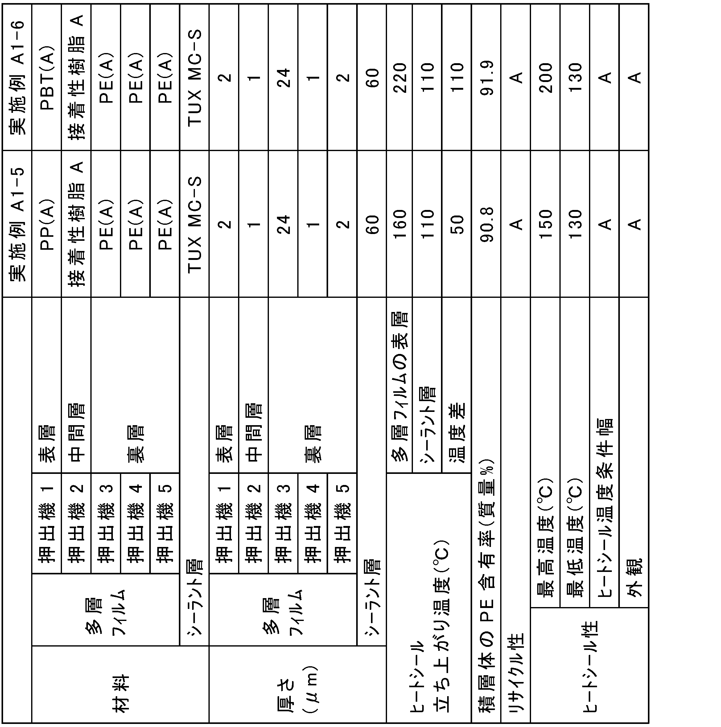

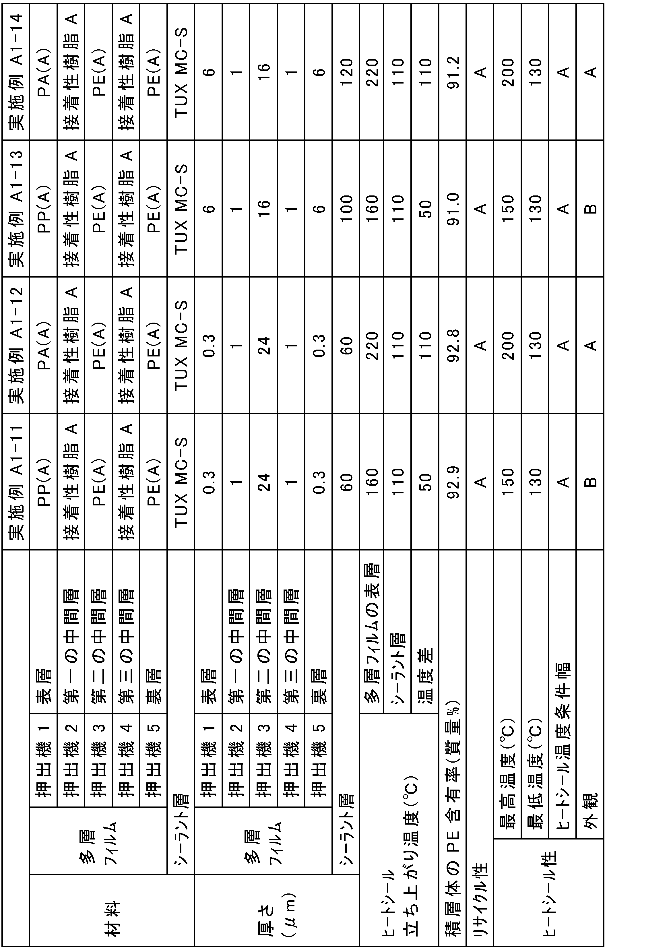
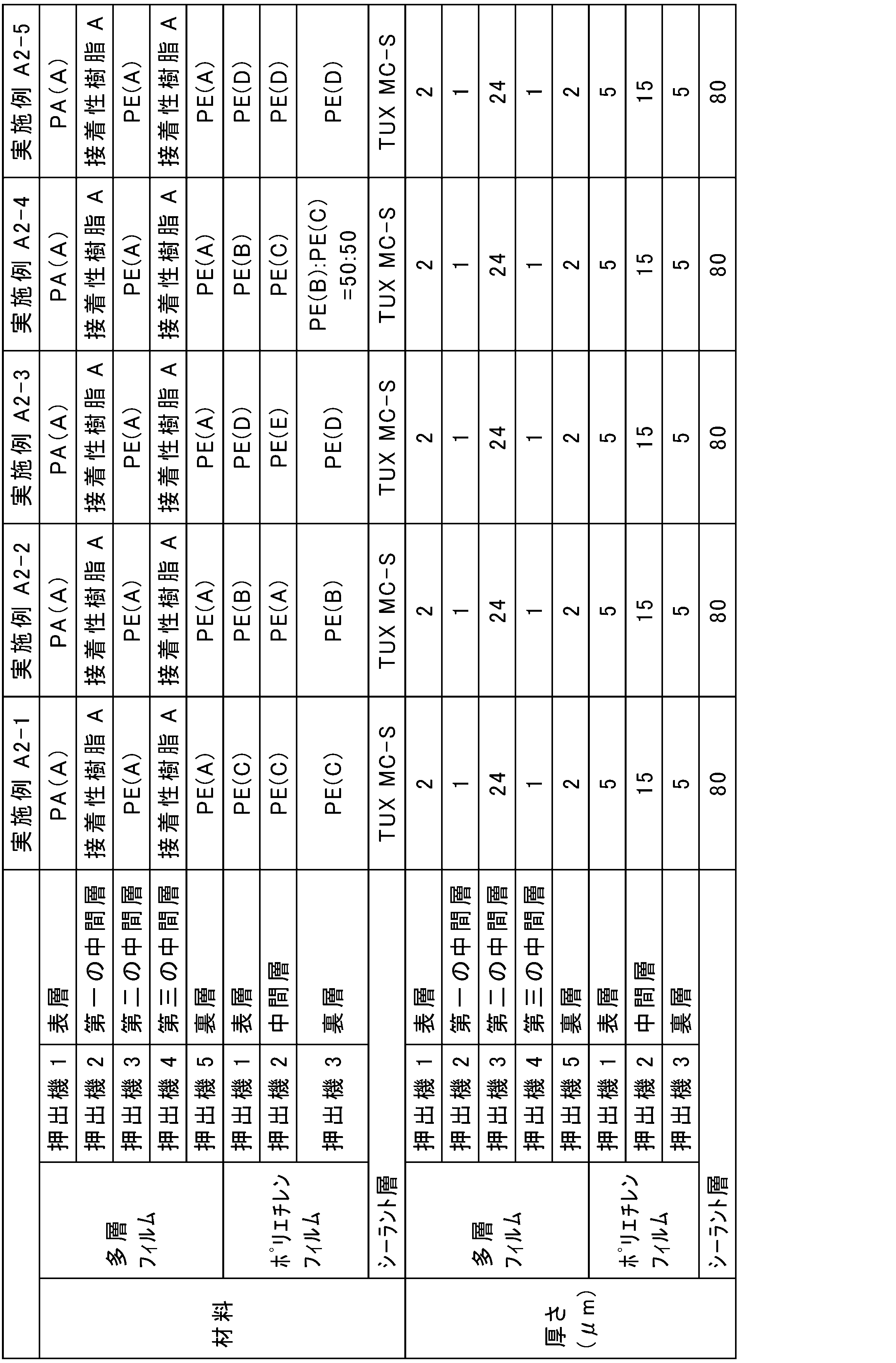
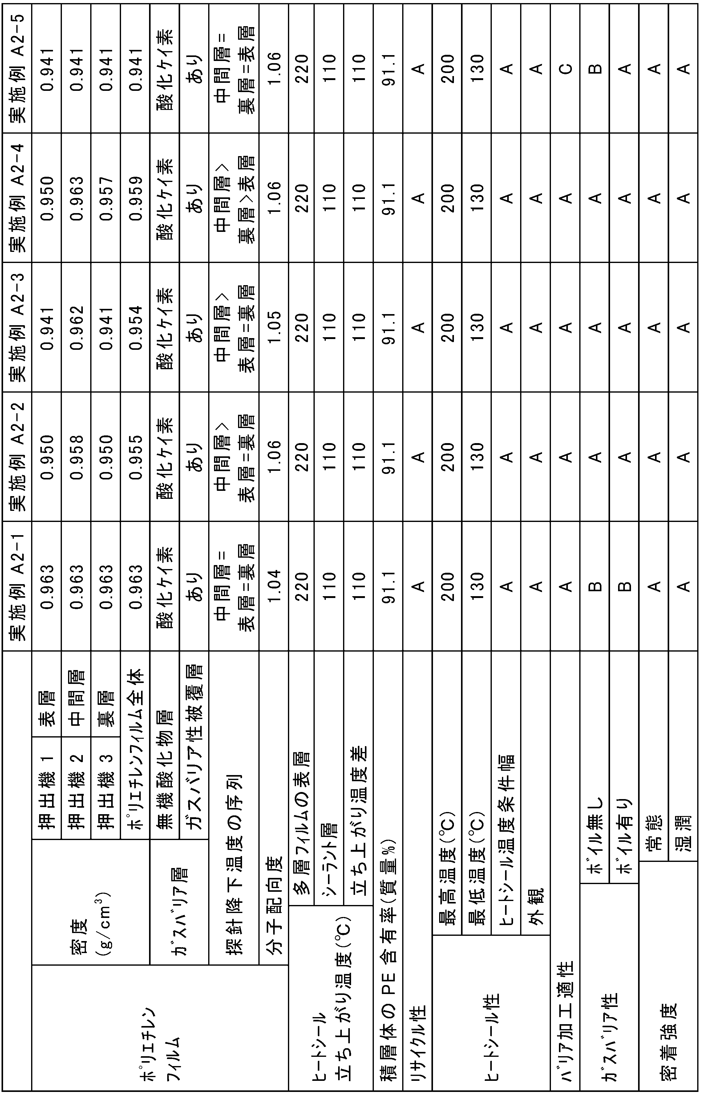


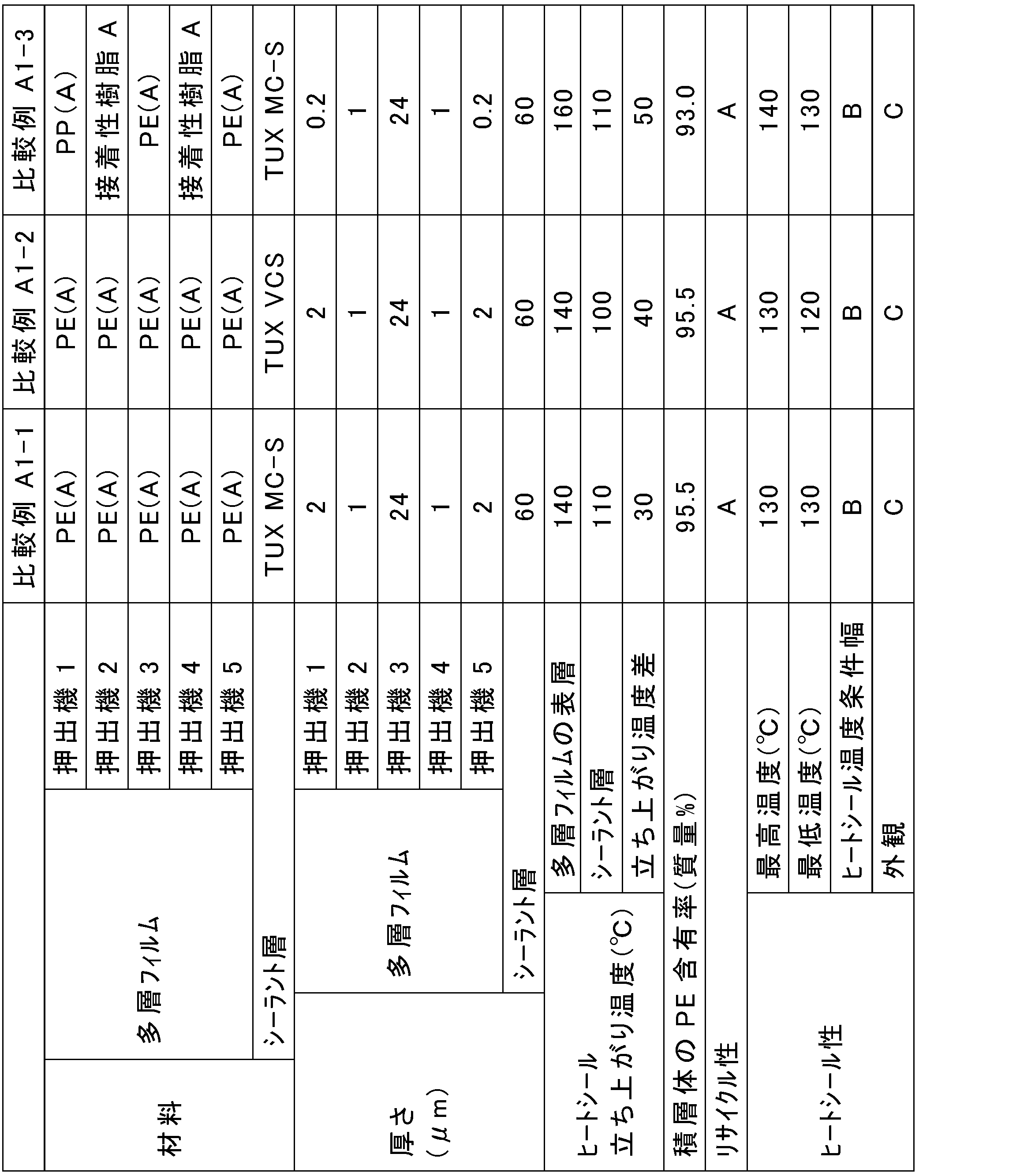
[材料]
第一の検討と同じ材料を準備した。
<実施例B1-1~B1-28、実施例B2-1~B2-21及び比較例B1~B4>
共押出空冷インフレーション法により共押出多層フィルムを作製した。具体的には、まず、押出機1~5を準備した。各押出機にそれぞれ表10~15、17、19、21及び23に示す材料を充填した。2種の材料を混合して用いた場合には材料名とその混合比率(質量比)を表中に示した。充填した材料を溶融混練(温度:190~230℃)した。各押出機から溶融した材料を押し出して積層し、空冷することで共押出多層フィルムを作製した。各押出機の材料は、厚さが表10~15、17、19、21及び23に示す値となるように押出した。表に示すとおり一部の共押出多層フィルムについては、MD方向に2~5倍の倍率で延伸処理した。
<実施例B2-1~B2-21>
共押出空冷インフレーション法により共押出多層フィルムを作製した。具体的には、まず、押出機1~3を準備した。各押出機にそれぞれ表15、17、19及び21に示す材料を充填した。充填した材料を溶融混練(温度:190~230℃)した。各押出機から溶融した材料を押し出して積層し、空冷することでポリエチレンフィルムを得た。得られたポリエチレンフィルムの表面をコロナ処理した。実施例B2-7及びB2-18のポリエチレンフィルムについては、MD方向に2~5倍の倍率で延伸処理した。
<実施例B1-1~1-28及び比較例B1~B4>
共押出多層フィルムの裏層側の表面とシーラント層とを接着剤Aを用いてドライラミネート法により貼り付けてエージング(温度:40℃、期間:4日間)することで積層体を得た。接着剤層の厚さは3μmであった。シーラント層には、表10~14及び23に示す材料を用いた。
実施例B2-1~B2-21に係る共押出多層フィルムを用い、表に示すシーラント層を用いたこと以外は、上述した第一の検討の実施例A2-1と同様にして積層体を得た。
各例で得られた積層体について下記の評価をした。結果を表に示した。リサイクル性、ヒートシール性、ヒートシール立ち上がり温度、バリア加工適性、ガスバリア性の評価、分子配向度、探針降下温度の測定は、上述した第一の検討と同様にして行った。
作製した共押出多層フィルムをTD方向200mm、MD方向200mmの大きさに切り取り、水平面上に静置して水平面から共押出多層フィルムの四隅までカールを観察した。カールの程度を下記の基準に沿って評価した。
(基準)
A:共押出多層フィルムにカールが見られない
B:共押出多層フィルムにわずかにカールが見られる
C:共押出多層フィルムが丸まる
(密着強度1)
各実施例及び比較例で得られた積層体から15mm幅の短冊状の試験片を切り出した。オリエンテック社製のテンシロン万能試験機RTC-1250を用いて試験片の端部から共押出多層フィルムとシーラント層との間を剥離して層間の密着強度を測定した。測定は、T型剥離で、常態(温度:23℃、湿度:50%RH)にて剥離速度300mm/minの条件で行った。また、剥離界面を水で濡らしながら剥離する湿潤(温度:23℃、湿度:50%RH)にて剥離速度300mm/minの条件で行った。
密着強度1と同様にして試験片を切り出した。密着強度1と同様の条件で共押出多層フィルムとポリエチレンフィルムとの間を剥離して層間の密着強度を測定した。また、湿潤にて同様に密着強度を測定した。
密着強度1と同様にして試験片を切り出した。密着強度1と同様の条件でポリエチレンフィルムとヒートシール層との間を剥離して層間の密着強度を測定した。また、湿潤にて同様に密着強度を測定した。結果を下記の基準に沿って評価した。
A:2N/15mm以上
B:2N/15mm未満
(湿潤の基準)
A:2N/15mm以上
B:2N/15mm未満
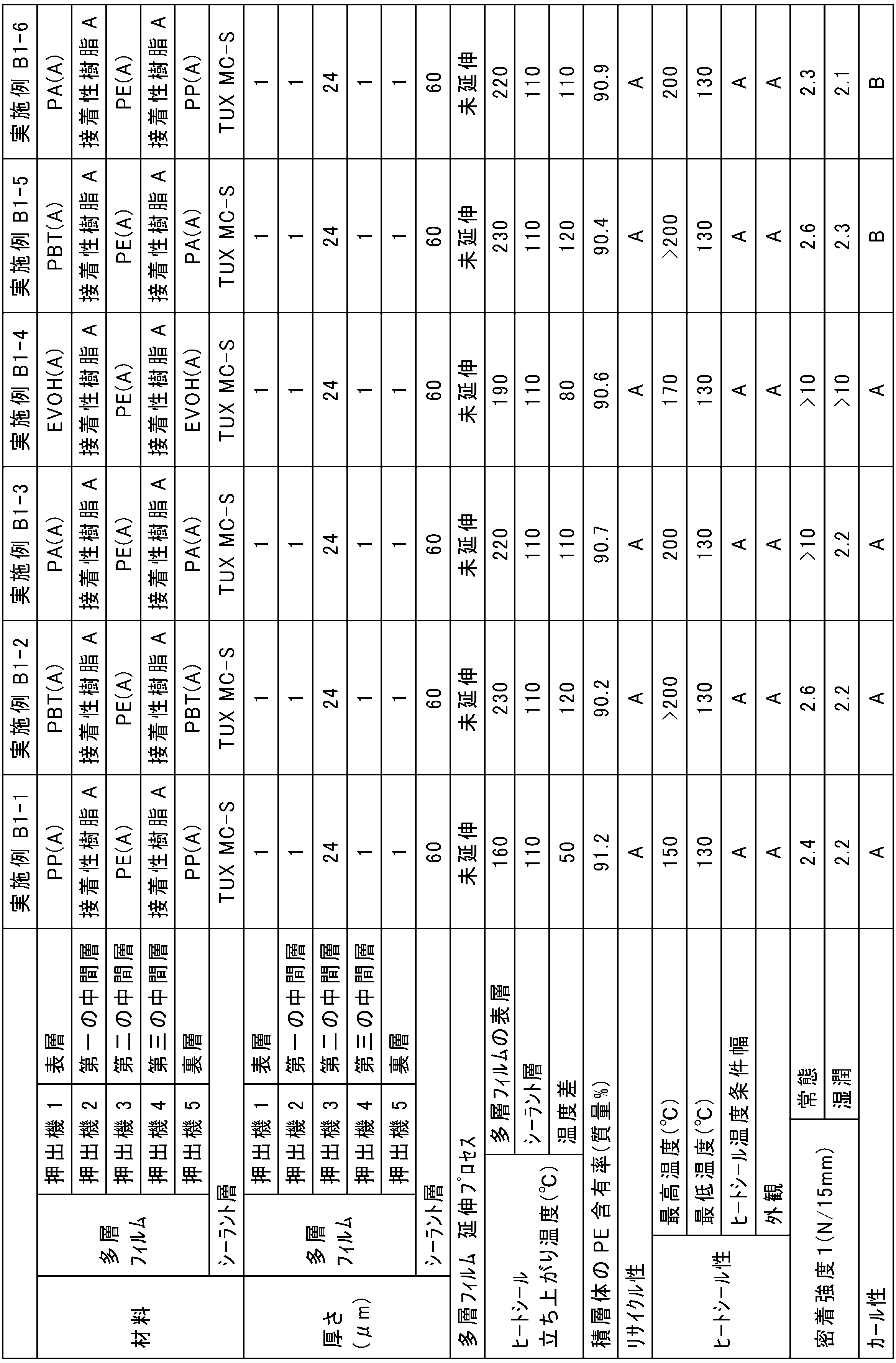


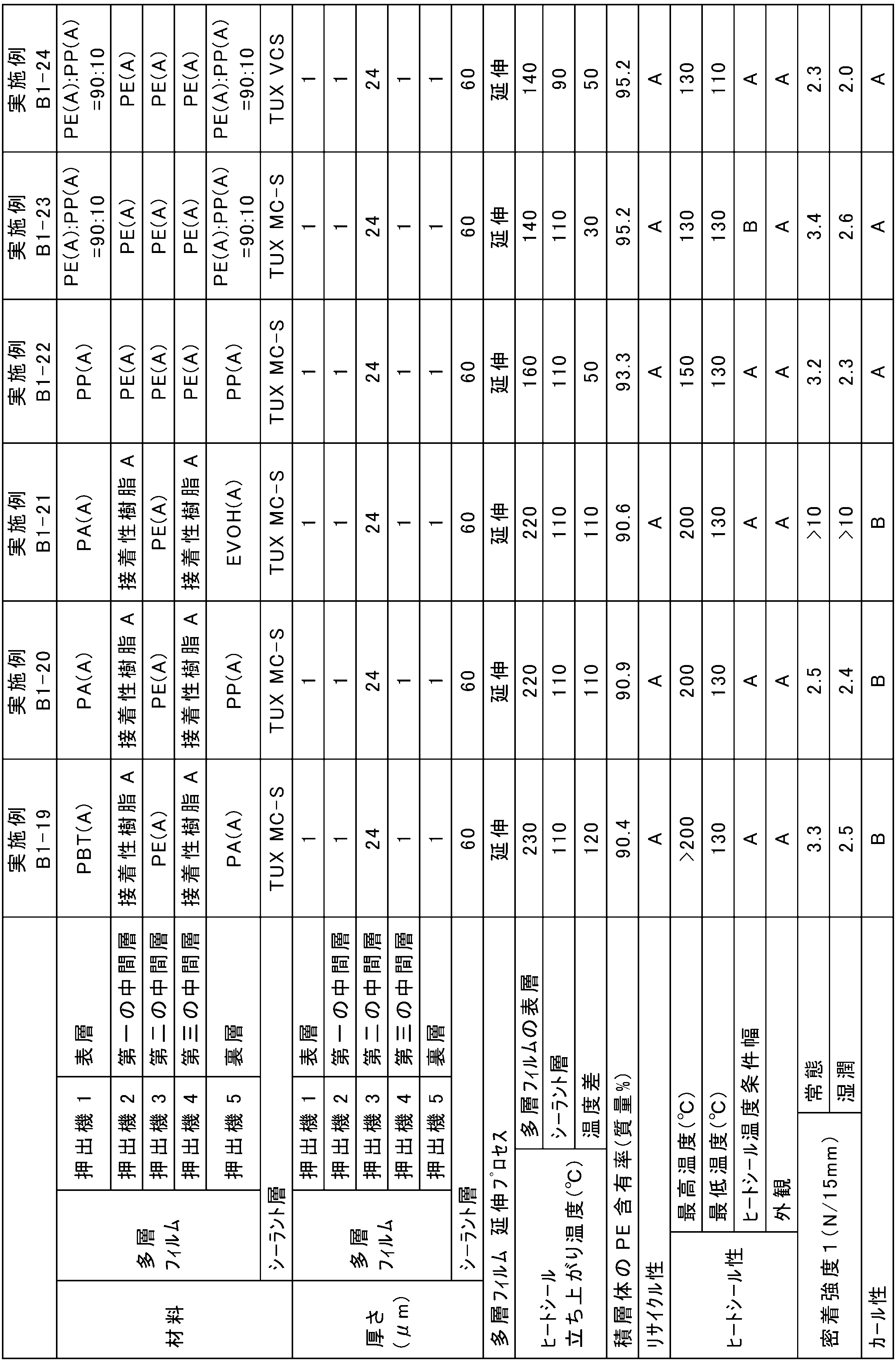


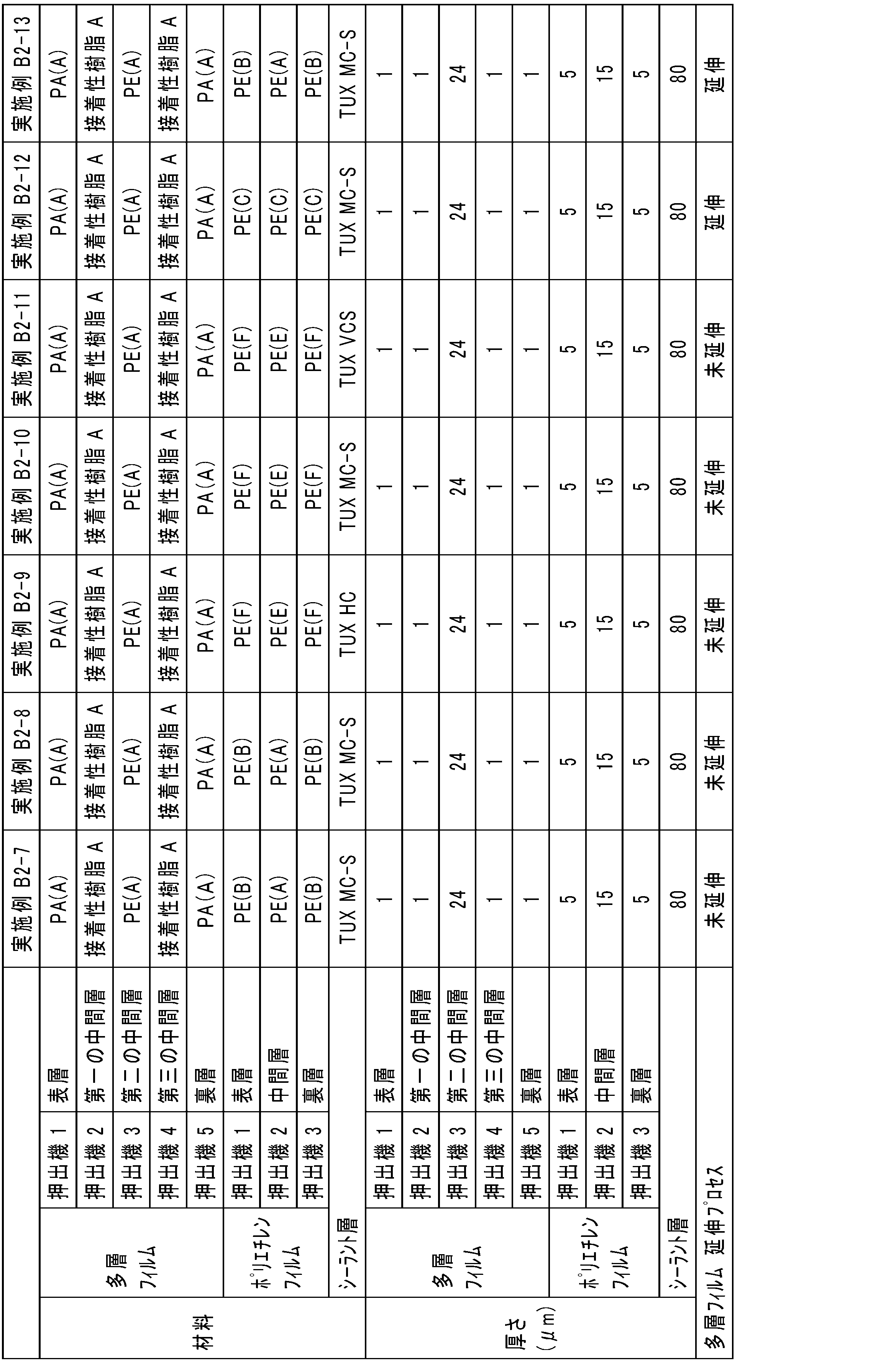

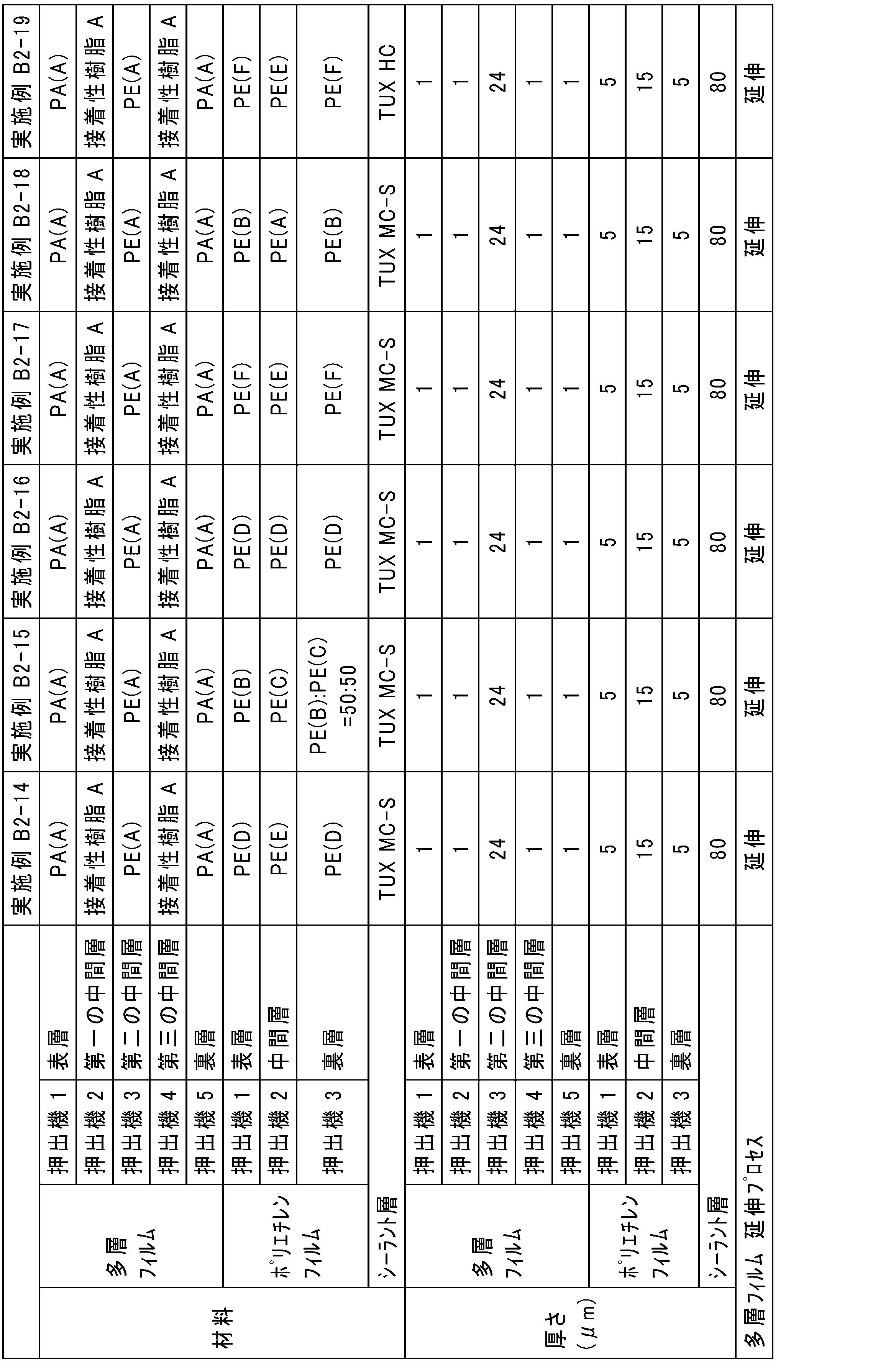


[1]第一の層と、第二の層と、を有する共押出多層フィルムであって、
第二の層が、ポリエチレン樹脂を含み、
第一の層が、ポリエチレン樹脂よりも融点が高い樹脂を含み、
第一の層の厚さが、0.3μm以上6μm以下である、共押出多層フィルム。
[2] 第二の層における第一の層とは反対側に第三の層を更に有し、
第三の層が、ポリエチレン樹脂よりも融点が高い樹脂を含む、[1]に記載の共押出多層フィルム。
[3][1]又は[2]に記載の共押出多層フィルムと、共押出多層フィルムの第二の層側に設けられた第一の接着剤層と、シーラント層と、をこの順序で備える積層体であって、
シーラント層が、ポリエチレン樹脂を含み、
積層体におけるポリエチレン樹脂の含有量が、積層体の全量を基準として90質量%以上である、積層体。
[4]共押出多層フィルムの表層のヒートシール立ち上がり温度とシーラント層のヒートシール立ち上がり温度との差が、40℃以上である、[3]に記載の積層体。
[5]第一の接着剤層とシーラント層との間に、第一の接着剤層側から、ポリエチレンフィルムと、第二の接着剤層と、を更に備える、[3]又は[4]に記載の積層体。
[6]ポリエチレンフィルムの分子配向度の絶対値が、1.07未満である、[5]に記載の積層体。
[7]ポリエチレンフィルムが、表層と、中間層と、裏層と、をこの順序で有し、
ポリエチレンフィルムにおいて、中間層の探針降下温度が、表層の探針降下温度よりも高く、且つ、裏層の探針降下温度以上であり、
ポリエチレンフィルムの表層が、0.926g/cm3以上の密度を有するポリエチレン樹脂を含む、[5]又は[6]に記載の積層体。
[8]共押出多層フィルムとポリエチレンフィルムとの間にガスバリア層を更に備える、[4]~[7]のいずれかに記載の積層体。
[9]ポリエチレンフィルムとシーラント層との間にガスバリア層を更に備える、[5]~[7]のいずれかに記載の積層体。
[10][3]~[9]のいずれかに記載の積層体を用いて形成された、包装袋。
Claims (10)
- 第一の層と、第二の層と、を有する共押出多層フィルムであって、
前記第二の層が、ポリエチレン樹脂を含み、
前記第一の層が、前記ポリエチレン樹脂よりも融点が高い樹脂を含み、
前記第一の層の厚さが、0.3μm以上6μm以下である、共押出多層フィルム。 - 前記第二の層における前記第一の層とは反対側に第三の層を更に有し、
前記第三の層が、前記ポリエチレン樹脂よりも融点が高い樹脂を含む、請求項1に記載の共押出多層フィルム。 - 請求項1又は2に記載の共押出多層フィルムと、前記共押出多層フィルムの前記第二の層側に設けられた第一の接着剤層と、シーラント層と、をこの順序で備える積層体であって、
前記シーラント層が、ポリエチレン樹脂を含み、
前記積層体におけるポリエチレン樹脂の含有量が、前記積層体の全量を基準として90質量%以上である、積層体。 - 前記共押出多層フィルムの表層のヒートシール立ち上がり温度と前記シーラント層のヒートシール立ち上がり温度との差が、40℃以上である、請求項3に記載の積層体。
- 前記第一の接着剤層と前記シーラント層との間に、前記第一の接着剤層側から、ポリエチレンフィルムと、第二の接着剤層と、を更に備える、請求項4に記載の積層体。
- 前記ポリエチレンフィルムの分子配向度の絶対値が、1.07未満である、請求項5に記載の積層体。
- 前記ポリエチレンフィルムが、表層と、中間層と、裏層と、をこの順序で有し、
前記ポリエチレンフィルムにおいて、前記中間層の探針降下温度が、前記表層の探針降下温度よりも高く、且つ、前記裏層の探針降下温度以上であり、
前記ポリエチレンフィルムの前記表層が、0.926g/cm3以上の密度を有するポリエチレン樹脂を含む、請求項5又は6に記載の積層体。 - 前記共押出多層フィルムと前記ポリエチレンフィルムとの間にガスバリア層を更に備える、請求項5~7のいずれか一項に記載の積層体。
- 前記ポリエチレンフィルムと前記シーラント層との間にガスバリア層を更に備える、請求項5~8のいずれか一項に記載の積層体。
- 請求項3~9のいずれか一項に記載の積層体を用いて形成された、包装袋。
Priority Applications (3)
| Application Number | Priority Date | Filing Date | Title |
|---|---|---|---|
| EP23885778.3A EP4578648A4 (en) | 2022-11-02 | 2023-10-31 | Co-extruded, laminated multi-layer film and packaging bag |
| CN202380065561.7A CN119866270A (zh) | 2022-11-02 | 2023-10-31 | 共挤出多层膜、层叠体以及包装袋 |
| AU2023372141A AU2023372141A1 (en) | 2022-11-02 | 2023-10-31 | Coextruded multilayer film, laminate, and packaging bag |
Applications Claiming Priority (4)
| Application Number | Priority Date | Filing Date | Title |
|---|---|---|---|
| JP2022-176673 | 2022-11-02 | ||
| JP2022176669A JP2024066888A (ja) | 2022-11-02 | 2022-11-02 | 共押出多層フィルム、積層体及び包装袋 |
| JP2022-176669 | 2022-11-02 | ||
| JP2022176673A JP2024066891A (ja) | 2022-11-02 | 2022-11-02 | 共押出多層フィルム、積層体及び包装袋 |
Publications (1)
| Publication Number | Publication Date |
|---|---|
| WO2024096024A1 true WO2024096024A1 (ja) | 2024-05-10 |
Family
ID=90930537
Family Applications (1)
| Application Number | Title | Priority Date | Filing Date |
|---|---|---|---|
| PCT/JP2023/039326 Ceased WO2024096024A1 (ja) | 2022-11-02 | 2023-10-31 | 共押出多層フィルム、積層体及び包装袋 |
Country Status (4)
| Country | Link |
|---|---|
| EP (1) | EP4578648A4 (ja) |
| CN (1) | CN119866270A (ja) |
| AU (1) | AU2023372141A1 (ja) |
| WO (1) | WO2024096024A1 (ja) |
Cited By (2)
| Publication number | Priority date | Publication date | Assignee | Title |
|---|---|---|---|---|
| WO2026029116A1 (ja) * | 2024-07-31 | 2026-02-05 | Toppanホールディングス株式会社 | 液体包装用ガスバリア性積層体、液体包装用フィルム、液体包装容器及び液体包装製品 |
| WO2026042584A1 (ja) * | 2024-08-22 | 2026-02-26 | Toppanホールディングス株式会社 | 積層体及び包装材料 |
Citations (5)
| Publication number | Priority date | Publication date | Assignee | Title |
|---|---|---|---|---|
| JP2020055157A (ja) | 2018-09-28 | 2020-04-09 | 大日本印刷株式会社 | 積層体、包装材料、包装袋およびスタンドパウチ |
| JP2020055158A (ja) * | 2018-09-28 | 2020-04-09 | 大日本印刷株式会社 | 積層体、包装材料、包装袋およびスタンドパウチ |
| JP2021160269A (ja) * | 2020-03-31 | 2021-10-11 | 大日本印刷株式会社 | 積層体および包装容器 |
| JP2021160262A (ja) * | 2020-03-31 | 2021-10-11 | 大日本印刷株式会社 | 積層体および包装容器 |
| JP2021160270A (ja) * | 2020-03-31 | 2021-10-11 | 大日本印刷株式会社 | 積層体および包装容器 |
Family Cites Families (3)
| Publication number | Priority date | Publication date | Assignee | Title |
|---|---|---|---|---|
| JP5459535B2 (ja) * | 2009-07-29 | 2014-04-02 | Dic株式会社 | 共押出多層フィルム及び該フィルムからなる包装材 |
| JP7192239B2 (ja) * | 2018-04-27 | 2022-12-20 | 大日本印刷株式会社 | 包装材料用ポリエチレン積層体及び該積層体からなる包装材料 |
| WO2022230812A1 (ja) * | 2021-04-26 | 2022-11-03 | 凸版印刷株式会社 | 積層体、包装材料及び包装袋 |
-
2023
- 2023-10-31 AU AU2023372141A patent/AU2023372141A1/en active Pending
- 2023-10-31 WO PCT/JP2023/039326 patent/WO2024096024A1/ja not_active Ceased
- 2023-10-31 CN CN202380065561.7A patent/CN119866270A/zh active Pending
- 2023-10-31 EP EP23885778.3A patent/EP4578648A4/en active Pending
Patent Citations (5)
| Publication number | Priority date | Publication date | Assignee | Title |
|---|---|---|---|---|
| JP2020055157A (ja) | 2018-09-28 | 2020-04-09 | 大日本印刷株式会社 | 積層体、包装材料、包装袋およびスタンドパウチ |
| JP2020055158A (ja) * | 2018-09-28 | 2020-04-09 | 大日本印刷株式会社 | 積層体、包装材料、包装袋およびスタンドパウチ |
| JP2021160269A (ja) * | 2020-03-31 | 2021-10-11 | 大日本印刷株式会社 | 積層体および包装容器 |
| JP2021160262A (ja) * | 2020-03-31 | 2021-10-11 | 大日本印刷株式会社 | 積層体および包装容器 |
| JP2021160270A (ja) * | 2020-03-31 | 2021-10-11 | 大日本印刷株式会社 | 積層体および包装容器 |
Non-Patent Citations (1)
| Title |
|---|
| See also references of EP4578648A4 |
Cited By (2)
| Publication number | Priority date | Publication date | Assignee | Title |
|---|---|---|---|---|
| WO2026029116A1 (ja) * | 2024-07-31 | 2026-02-05 | Toppanホールディングス株式会社 | 液体包装用ガスバリア性積層体、液体包装用フィルム、液体包装容器及び液体包装製品 |
| WO2026042584A1 (ja) * | 2024-08-22 | 2026-02-26 | Toppanホールディングス株式会社 | 積層体及び包装材料 |
Also Published As
| Publication number | Publication date |
|---|---|
| EP4578648A4 (en) | 2025-12-10 |
| EP4578648A1 (en) | 2025-07-02 |
| CN119866270A (zh) | 2025-04-22 |
| AU2023372141A1 (en) | 2025-03-27 |
Similar Documents
| Publication | Publication Date | Title |
|---|---|---|
| JP7180072B2 (ja) | 積層フィルム及び包装袋 | |
| WO2022131264A1 (ja) | 積層体、包装袋及びスタンディングパウチ | |
| JP7677515B2 (ja) | ガスバリア積層体 | |
| WO2024096024A1 (ja) | 共押出多層フィルム、積層体及び包装袋 | |
| WO2023243607A1 (ja) | 積層体及びその製造方法、並びに、包装袋 | |
| JP7231095B2 (ja) | 積層体及び包装袋 | |
| JP7593535B1 (ja) | 包装フィルム、包装容器及び包装製品 | |
| JP7786251B2 (ja) | 包装材料 | |
| JP2024066888A (ja) | 共押出多層フィルム、積層体及び包装袋 | |
| JP2024066891A (ja) | 共押出多層フィルム、積層体及び包装袋 | |
| WO2023238825A1 (ja) | 包装用の積層体及び包装袋 | |
| JP2023183634A (ja) | 積層体及びその製造方法、並びに、包装袋 | |
| US20260124824A1 (en) | Coextruded multilayer film, laminate, and packaging bag | |
| US20250303678A1 (en) | Laminate and packaging bag | |
| JP2024176275A (ja) | 積層体及び包装材料 | |
| JP2025097046A (ja) | 多層フィルム、積層体、包装袋、包装製品及び多層フィルムの選定方法 | |
| JP2023179896A (ja) | 積層体、包装材料及び包装袋 | |
| JP7460011B1 (ja) | 包装フィルム、包装袋及び包装製品 | |
| JP7485173B1 (ja) | 包装フィルム、包装袋及び包装製品 | |
| JP7279363B2 (ja) | ガスバリアフィルムおよび包装用フィルム | |
| JP2023178816A (ja) | 包装用積層体及び包装袋 | |
| JP2024178622A (ja) | 積層体、包装材料及び包装体 | |
| JP2026010976A (ja) | 積層体、包装材料及び包装体 | |
| JP2023183633A (ja) | 積層体及びその製造方法、並びに、包装袋 | |
| JP2024099158A (ja) | 包装袋の製造方法及び包装袋 |
Legal Events
| Date | Code | Title | Description |
|---|---|---|---|
| 121 | Ep: the epo has been informed by wipo that ep was designated in this application |
Ref document number: 23885778 Country of ref document: EP Kind code of ref document: A1 |
|
| WWE | Wipo information: entry into national phase |
Ref document number: AU2023372141 Country of ref document: AU Ref document number: 202380065561.7 Country of ref document: CN |
|
| WWE | Wipo information: entry into national phase |
Ref document number: 2023885778 Country of ref document: EP Ref document number: 23885778 Country of ref document: EP |
|
| ENP | Entry into the national phase |
Ref document number: 2023372141 Country of ref document: AU Date of ref document: 20231031 Kind code of ref document: A |
|
| ENP | Entry into the national phase |
Ref document number: 2023885778 Country of ref document: EP Effective date: 20250325 |
|
| WWP | Wipo information: published in national office |
Ref document number: 202380065561.7 Country of ref document: CN |
|
| NENP | Non-entry into the national phase |
Ref country code: DE |
|
| WWP | Wipo information: published in national office |
Ref document number: 2023885778 Country of ref document: EP |