WO2024098301A1 - 信号传输方法和装置 - Google Patents
信号传输方法和装置 Download PDFInfo
- Publication number
- WO2024098301A1 WO2024098301A1 PCT/CN2022/130960 CN2022130960W WO2024098301A1 WO 2024098301 A1 WO2024098301 A1 WO 2024098301A1 CN 2022130960 W CN2022130960 W CN 2022130960W WO 2024098301 A1 WO2024098301 A1 WO 2024098301A1
- Authority
- WO
- WIPO (PCT)
- Prior art keywords
- sequence set
- complementary sequence
- permutation
- permuted
- finite field
- Prior art date
- Legal status (The legal status is an assumption and is not a legal conclusion. Google has not performed a legal analysis and makes no representation as to the accuracy of the status listed.)
- Ceased
Links
Images


Classifications
-
- H—ELECTRICITY
- H04—ELECTRIC COMMUNICATION TECHNIQUE
- H04W—WIRELESS COMMUNICATION NETWORKS
- H04W74/00—Wireless channel access
- H04W74/08—Non-scheduled access, e.g. ALOHA
- H04W74/0833—Random access procedures, e.g. with 4-step access
-
- H—ELECTRICITY
- H04—ELECTRIC COMMUNICATION TECHNIQUE
- H04J—MULTIPLEX COMMUNICATION
- H04J13/00—Code division multiplex systems
-
- H—ELECTRICITY
- H04—ELECTRIC COMMUNICATION TECHNIQUE
- H04J—MULTIPLEX COMMUNICATION
- H04J13/00—Code division multiplex systems
- H04J13/0007—Code type
- H04J13/0055—ZCZ [zero correlation zone]
-
- H—ELECTRICITY
- H04—ELECTRIC COMMUNICATION TECHNIQUE
- H04J—MULTIPLEX COMMUNICATION
- H04J13/00—Code division multiplex systems
- H04J13/10—Code generation
- H04J13/14—Generation of codes with a zero correlation zone
Definitions
- the present application relates to the field of communication technology, and in particular to a signal transmission method and device.
- the ideal autocorrelation and ideal cross-correlation characteristics of sequences have very important applications in wireless communications.
- the ideal autocorrelation characteristic means that the correlation value between a sequence and any non-zero shift is zero
- the ideal cross-correlation characteristic means that the correlation value of any shift of two sequences is zero.
- Periodic correlation refers to the cyclic shift correlation of the sequence, and the overlapping part of the sequence is always equal to the sequence length.
- Non-periodic correlation refers to the zero-filled shift correlation of the sequence, and the overlapping part of the sequence is usually less than the sequence length.
- periodic correlation sequences there are sequences with ideal autocorrelation characteristics and sequences with ideal mutual correlation characteristics, but there is no sequence with both ideal autocorrelation and ideal mutual correlation characteristics.
- non-periodic correlation sequences there is no sequence with ideal autocorrelation characteristics, nor is there a sequence with ideal mutual correlation characteristics.
- uplink random access uses the periodic correlation characteristics of the Zadoff-Chu sequence (also called the ZC sequence) and uses the ZC sequence to add a cyclic prefix to achieve ideal autocorrelation.
- ZC sequence also called the ZC sequence
- the embodiments of the present application provide a signal transmission method and device, which can reduce the time-frequency resource overhead of signal transmission, improve spectrum efficiency, and thus improve system performance.
- a signal transmission method comprising: determining a permutation complementary sequence set, the permutation complementary sequence set comprising M member sequences, the member sequence comprising N member symbols, M and N are both integers greater than 1, the member symbols are obtained by performing a permutation operation on parameters of the permutation complementary sequence set, the permutation operation is a single mapping operation within a finite field, and the permutation complementary sequence set satisfies non-periodic correlation; and sending a signal based on the permutation complementary sequence set.
- the signal transmission method provided by the present application performs a single mapping operation in a finite field on the parameters in the permutation complementary sequence set to obtain a member symbol of the permutation complementary sequence set, obtains a member sequence of the permutation complementary sequence set according to the member symbol, and then determines the permutation complementary sequence set according to the member sequence, and the permutation complementary sequence set satisfies the non-periodic correlation. Since the permutation complementary sequence set satisfies the non-periodic correlation, when sending a signal through the permutation complementary sequence set, the transmitting end does not need to add a cyclic prefix when determining the signal to be sent, which can reduce the time-frequency resource overhead of signal transmission, improve spectrum efficiency, and thus improve system performance.
- the parameters of the permutation complementary sequence set include at least one of the following: a length N of a member sequence in the permutation complementary sequence set, a number M of member sequences, and a length Z of a zero correlation zone in the permutation complementary sequence set, where Z is an integer greater than or equal to 1.
- the number of permutation complementary sequence sets is Among them, the lth replacement complementary sequence set s [k][l] in the kth replacement complementary sequence set is expressed as:
- N is greater than or equal to M
- M is greater than or equal to Z
- M is divisible by Z, k ⁇ 1,2,...,Z-1 ⁇ , Replace the nth member symbol of the mth member sequence in the complementary sequence set s [k][l] Expressed as:
- the permuted complementary sequence set obtained in the embodiment of the present application satisfies non-periodic correlation.
- the transmitter does not need to add a cyclic prefix when determining the signal to be sent, which can reduce the time-frequency resource overhead of signal transmission, improve spectrum efficiency, and thus improve system performance.
- the permuted complementary sequence set obtained in the embodiment of the present application does not need to add a cyclic prefix, which reduces overhead, improves spectrum efficiency, and also increases sequence capacity.
- N>M Z.
- the sequence obtained by this implementation method reduces overhead and improves spectrum efficiency while also increasing sequence capacity, and can improve the signal detection capability of the receiving end in scenarios with high noise or scenarios where the receiving end has high requirements for signal detection performance.
- the sequence obtained by this implementation reduces overhead and improves spectrum efficiency, and is suitable for multi-user access scenarios.
- the permutation complementary sequence set is a partial sequence set in the candidate permutation complementary sequence set, and the number of the candidate permutation complementary sequence set is Among them, the lth replacement complementary sequence set s [k][l] in the kth replacement complementary sequence set is expressed as:
- M is divisible by Z, k ⁇ 1,2,...,Z-1 ⁇ , Replace the nth member symbol of the mth member sequence in the complementary sequence set s [k][l] Expressed as:
- the embodiment of the present application obtains a permuted complementary sequence set by limiting the sequence set index number within the group of the candidate permuted complementary sequence set, so that the transmitter does not need to add a cyclic prefix, which reduces overhead and improves spectrum efficiency while also improving sequence capacity, and is suitable for high-speed mobile communication scenarios.
- the permutation complementary sequence set is a sequence set in which l of the candidate permutation complementary sequence sets belongs to the following set:
- f is a positive integer.
- the permutation complementary sequence set obtained in the embodiment of the present application has a number of permutation complementary sequence sets within the group that is close to 1/3 of the number of candidate permutation complementary sequence sets. Compared with the restricted set of ZC sequences, it is beneficial to increase the number of valid sequence sets, improves the sequence capacity, and is suitable for high-speed mobile communication scenarios.
- sending a signal based on a permutation complementary sequence set includes: determining a target permutation complementary sequence set from the permutation complementary sequence set; mapping the target permutation complementary sequence set to N member symbols and M subcarriers, generating the above-mentioned signal, and sending the signal.
- sending a signal based on a permuted complementary sequence set includes: a terminal device sending a random access signal to a network device based on the permuted complementary sequence set.
- the member sequence length N and the member sequence number M are sent by the network device to the terminal device, or are agreed upon by a protocol.
- a signal transmission device which may be a terminal device or a network device, or a device in the terminal device or the network device (for example, a chip, or a chip system, or a circuit), or a device that can be used in combination with the terminal device or the network device.
- the device may include a module or unit corresponding to each of the methods/operations/steps/actions described in the first aspect.
- the module or unit may be a hardware circuit, software, or a combination of hardware circuit and software.
- the device includes: a processing unit, used to determine a permutation complementary sequence set, the permutation complementary sequence set includes M member sequences, the member sequence includes N member symbols, M and N are both integers greater than 1, the above member symbols are obtained by performing a permutation operation on parameters of the permutation complementary sequence set, the permutation operation is a single mapping operation within a finite field, and the permutation complementary sequence set satisfies non-periodic correlation; a transceiver unit, used to send a signal based on the permutation complementary sequence set.
- the parameters of the permutation complementary sequence set include at least one of the following: the length N of the member sequence in the permutation complementary sequence set, the number M of the member sequences, and the length Z of the zero correlation zone in the permutation complementary sequence set, where Z is an integer greater than or equal to 1.
- the number of permutation complementary sequence sets is Among them, the lth replacement complementary sequence set s [k][l] in the kth replacement complementary sequence set is expressed as:
- N is greater than or equal to M
- M is greater than or equal to Z
- M is divisible by Z, k ⁇ 1,2,...,Z-1 ⁇ , Replace the nth member symbol of the mth member sequence in the complementary sequence set s [k][l] Expressed as:
- N>M Z.
- the permutation complementary sequence set is a partial sequence set in a candidate permutation complementary sequence set
- the number of the candidate permutation complementary sequence set is Among them, the lth replacement complementary sequence set s [k][l] in the kth replacement complementary sequence set is expressed as:
- M is divisible by Z, k ⁇ 1,2,...,Z-1 ⁇ , Replace the nth member symbol of the mth member sequence in the complementary sequence set s [k][l] Expressed as:
- the permutation complementary sequence set is a sequence set in which l of the candidate permutation complementary sequence sets belongs to the following set:
- f is a positive integer.
- the processing unit is further used to: determine a target permutation complementary sequence set from the permutation complementary sequence set; map the target permutation complementary sequence set to N member symbols and M subcarriers to generate a signal; and the transceiver unit is further used to: send a signal.
- the transceiver unit is further configured to: send a random access signal to the network device based on the permuted complementary sequence set.
- the member sequence length N and the member sequence number M are sent by the network device to the apparatus, or are agreed upon by the protocol.
- a signal transmission device comprising: a processor, the processor is coupled to a memory, the memory is used to store a computer program, when the processor calls the computer program, the device executes a method in any possible implementation of the first aspect.
- processors there are one or more processors and one or more memories.
- the memory may be integrated with the processor, or the memory may be provided separately from the processor.
- the memory can be a non-transitory memory, such as a read-only memory (ROM), which can be integrated with the processor on the same chip or can be separately set on different chips.
- ROM read-only memory
- the embodiments of the present application do not limit the type of memory and the setting method of the memory and the processor.
- the relevant data interaction process such as sending the connection data request information
- receiving the capability information can be a process of receiving the input capability information from the processor.
- the processed output data can be output to the transmitter, and the input data received by the processor can come from the receiver.
- the transmitter and the receiver can be collectively referred to as a transceiver.
- the device in the third aspect mentioned above can be a chip, and the processor can be implemented by hardware or by software.
- the processor can be a logic circuit, an integrated circuit, etc.; when implemented by software, the processor can be a general-purpose processor, which is implemented by reading the software code stored in the memory.
- the memory can be integrated in the processor or can be located outside the processor and exist independently.
- a computer-readable storage medium which stores a computer program (also referred to as code or instruction), which, when executed on a computer, enables the computer to execute a method in any possible implementation of the first aspect.
- a computer program also referred to as code or instruction
- a computer program product comprising: a computer program (also referred to as code, or instruction), which, when executed, enables a computer to execute a method in any possible implementation of the first aspect.
- a computer program also referred to as code, or instruction
- a communication system including a terminal device and a network device, wherein the terminal device or the network device is used to implement the above-mentioned first aspect or any possible implementation method of the first aspect.
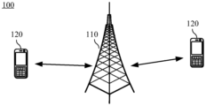
- FIG1 is a schematic diagram of a communication system used in an embodiment of the present application.
- FIG2 is a schematic diagram of a period-related sequence provided in an embodiment of the present application.
- FIG3 is a schematic diagram of a non-periodic correlation sequence provided in an embodiment of the present application.
- FIG4 is a schematic diagram of a time-frequency resource configuration format of a physical random access channel provided in an embodiment of the present application
- FIG5 is a schematic diagram of another physical random access channel time-frequency resource configuration format provided in an embodiment of the present application.
- FIG6 is a schematic flow chart of a signal transmission method provided in an embodiment of the present application.
- FIG7 is a schematic diagram of a mutual correlation characteristic of a permuted complementary sequence set provided in an embodiment of the present application.
- FIG8 is a schematic diagram of the cross-correlation characteristics of another permuted complementary sequence set provided in an embodiment of the present application.
- FIG9 is a schematic diagram of the cross-correlation characteristics of yet another permuted complementary sequence set provided in an embodiment of the present application.
- FIG10 is a schematic diagram of a ZC sequence and a candidate permuted complementary sequence set provided in an embodiment of the present application using a restricted set for frequency offset resistance comparison;
- FIG11 is a schematic block diagram of a signal transmission device provided in an embodiment of the present application.
- FIG. 12 is a schematic block diagram of another signal transmission device provided in an embodiment of the present application.
- words such as “first” and “second” are used to distinguish the same or similar items with substantially the same functions and effects. Those skilled in the art can understand that words such as “first” and “second” do not limit the quantity and execution order, and words such as “first” and “second” do not necessarily limit the difference.
- At least one refers to one or more
- plural refers to two or more.
- And/or describes the association relationship of associated objects, indicating that three relationships may exist.
- a and/or B can represent: A exists alone, A and B exist at the same time, and B exists alone, where A and B can be singular or plural.
- the character “/” generally indicates that the objects associated before and after are in an “or” relationship.
- At least one of the following” or similar expressions refers to any combination of these items, including any combination of single or plural items.
- At least one of a, b, or c can represent: a, b, c, a-b, a--c, b-c, or a-b-c, where a, b, c can be single or multiple.
- LTE long term evolution
- FDD frequency division duplex
- TDD LTE time division duplex
- 5G fifth generation mobile communication system
- NR new radio
- the terminal device in the embodiments of the present application may also be referred to as: user equipment (UE), mobile station (MS), mobile terminal (MT), access terminal, user unit, user station, mobile station, mobile station, remote station, remote terminal, mobile device, user terminal, terminal, wireless communication equipment, user agent or user device, etc.
- UE user equipment
- MS mobile station
- MT mobile terminal
- access terminal user unit, user station, mobile station, mobile station, remote station, remote terminal, mobile device, user terminal, terminal, wireless communication equipment, user agent or user device, etc.
- a terminal device can be a device that provides voice/data connectivity to users, such as a handheld device with wireless connection function, a vehicle-mounted device, etc.
- terminal devices include: mobile phones, tablet computers, laptops, PDAs, mobile internet devices (MID), wearable devices, drones, robots, smart point of sale (POS), customer-premises equipment (CPE), virtual reality (VR) equipment, augmented reality (AR) equipment, wireless terminals in industrial control, wireless terminals in self-driving, wireless terminals in remote medical surgery, wireless terminals in smart grids, wireless terminals in transportation safety, wireless terminals in smart cities, and wireless terminals in smart homes.
- MID mobile internet devices
- POS customer-premises equipment
- VR virtual reality
- AR augmented reality
- the present application does not limit the wireless terminals in the present invention, such as wireless terminals in smart home, cellular phones, cordless phones, session initiation protocol (SIP) phones, wireless local loop (WLL) stations, personal digital assistants (PDA), handheld devices with wireless communication functions, computing devices or other processing devices connected to wireless modems, vehicle-mounted devices, wearable devices, terminal devices in 5G networks or terminal devices in future evolved public land mobile communication networks (PLMN), etc.
- wireless terminals in smart home cellular phones, cordless phones, session initiation protocol (SIP) phones, wireless local loop (WLL) stations, personal digital assistants (PDA), handheld devices with wireless communication functions, computing devices or other processing devices connected to wireless modems, vehicle-mounted devices, wearable devices, terminal devices in 5G networks or terminal devices in future evolved public land mobile communication networks (PLMN), etc.
- PLMN public land mobile communication networks
- the terminal device may be a terminal device in an Internet of Things (IoT) system.
- IoT Internet of Things
- the Internet of Things is an important part of the future development of information technology. Its main technical feature is to connect objects to the network through communication technology, thereby realizing an intelligent network of human-machine interconnection and object-to-object interconnection.
- the terminal device in the embodiment of the present application may be a wearable device.
- Wearable devices may also be called wearable smart devices, which are a general term for wearable devices that are designed and developed using wearable technology for daily wear, such as glasses, gloves, watches, clothing and shoes. Wearable devices are portable devices that can be worn directly on the body or integrated into the user's clothes or accessories.
- Wearable devices are not only hardware devices, but also can realize powerful functions through software support, data interaction, and cloud interaction. Broadly speaking, wearable smart devices include full-featured, large-size, and can realize complete or partial functions without relying on smartphones, such as smart watches or smart glasses, and only focus on a certain type of application functions, and need to be used in conjunction with other devices such as smartphones, such as various types of smart bracelets and smart jewelry for vital sign monitoring.
- the terminal device may also be a terminal device in machine type communication (MTC).
- MTC machine type communication
- the terminal device may also be a vehicle-mounted module, a vehicle-mounted module, a vehicle-mounted component, a vehicle-mounted chip or a vehicle-mounted unit, etc., which is built into the vehicle as one or more components or units.
- the vehicle can implement the method provided by the present application through the built-in vehicle-mounted module, vehicle-mounted module, vehicle-mounted component, vehicle-mounted chip or vehicle-mounted unit, etc. Therefore, the embodiments of the present application may also be applied to the Internet of Vehicles, such as vehicle to everything (V2X), long-term evolution-vehicle (LTE-V), vehicle-to-vehicle (V2V) technology, etc.
- V2X vehicle to everything
- LTE-V long-term evolution-vehicle
- V2V vehicle-to-vehicle
- the network device involved in the present application can be a device that communicates with a terminal device.
- the network device can also be called an access network device or a wireless access network device. It can be a transmission reception point (TRP), an evolved NodeB (eNB or eNodeB) in an LTE system, a home base station (for example, home evolved NodeB, or home Node B, HNB), a baseband unit (BBU), or a wireless controller in a cloud radio access network (CRAN) scenario, or the network device can be a relay station, an access point, a vehicle-mounted device, a wearable device, a network device in a 5G network, or a network device in a future evolved PLMN network, etc.
- TRP transmission reception point
- eNB or eNodeB evolved NodeB
- HNB home evolved NodeB
- BBU baseband unit
- CRAN cloud radio access network
- the network device can be a relay station, an access point, a vehicle-mounted device, a
- the above network devices can also be urban base stations, micro base stations, pico base stations, femto base stations, etc., and the present application does not limit this.
- the network device may include a centralized unit (CU) node, a distributed unit (DU) node, a radio access network (RAN) device including a CU node and a DU node, or a RAN device including a control plane CU node (CU-CP node) and a user plane CU node (CU-UP node) and a DU node.
- CU centralized unit
- DU distributed unit
- RAN radio access network
- RAN radio access network
- the network equipment provides services for the cell, and the terminal equipment communicates with the cell through the transmission resources (for example, frequency domain resources, or spectrum resources) allocated by the network equipment.
- the cell can belong to a macro base station (for example, macro eNB or macro gNB, etc.), or to a base station corresponding to a small cell.
- the small cell here may include: metro cell, micro cell, pico cell, femto cell, etc. These small cells have the characteristics of small coverage and low transmission power, and are suitable for providing high-speed data transmission services.
- the terminal device or network device may include a hardware layer, an operating system layer running on the hardware layer, and an application layer running on the operating system layer.
- the hardware layer includes hardware such as a central processing unit (CPU), a memory management unit (MMU), and a memory (also called main memory).
- the operating system may be any one or more computer operating systems that implement business processing through a process, such as a Linux operating system, a Unix operating system, an Android operating system, an iOS operating system, or a Windows operating system.
- the application layer includes applications such as a browser, an address book, a word processing software, and an instant messaging software.
- the embodiment of the present application does not specifically limit the specific structure of the execution subject of the method provided in the embodiment of the present application, as long as it can communicate according to the method provided in the embodiment of the present application, for example, the execution subject of the method provided in the embodiment of the present application may be a terminal device or a network device, or a functional module in a terminal device or a network device that can execute a program.
- computer-readable media may include, but are not limited to: magnetic storage devices (e.g., hard disks, floppy disks, or tapes, etc.), optical disks (e.g., compact disks (CDs), digital versatile disks (DVDs), etc.), smart cards and flash memory devices (e.g., erasable programmable read-only memory (EPROM), cards, sticks or key drives, etc.).
- magnetic storage devices e.g., hard disks, floppy disks, or tapes, etc.
- optical disks e.g., compact disks (CDs), digital versatile disks (DVDs), etc.
- smart cards and flash memory devices e.g., erasable programmable read-only memory (EPROM), cards, sticks or key drives, etc.
- various storage media described herein may represent one or more devices and/or other machine-readable media for storing information.
- machine-readable medium may include, but is not limited to, various other media that can store, contain and/or carry instructions and/or data.
- FIG. 1 To facilitate understanding of the embodiments of the present application, a communication system applicable to the embodiments of the present application is first described in detail in conjunction with FIG. 1 .
- FIG. 1 shows a communication system 100 to which an embodiment of the present application can be applied.
- the communication system 100 may include at least one network device, such as the network device 110 shown in FIG. 1 ; the communication system 100 may also include at least one terminal device, such as the terminal device 120 shown in FIG. 1 .
- the network device 110 and the terminal device 120 may communicate via a wireless link.
- Each communication device, such as the network device 110 or the terminal device 120 may be configured with multiple antennas, which may include at least one transmitting antenna for sending signals and at least one receiving antenna for receiving signals.
- each communication device also additionally includes a transmitter chain and a receiver chain, and those skilled in the art may understand that they may include multiple components related to signal transmission and signal reception (such as processors, modulators, multiplexers, demodulators, demultiplexers or antennas, etc.). Therefore, the network device 110 and the terminal device 120 may communicate via a multi-antenna technology.
- Figure 1 exemplarily shows a network device and two terminal devices.
- the communication system 100 may include multiple network devices and the coverage area of each network device may include other numbers of terminal devices, which is not limited in the embodiments of the present application.
- Periodic correlation refers to the cyclic shift correlation of the sequence. The overlapping part of the sequence is always equal to the sequence length.
- v* is the conjugate of the complex number v
- ⁇ is the delay of the sequence v.
- FIG2 is a schematic diagram of a periodically correlated sequence.
- sequence u [u 0 , u 1 , u 2 , u 3 , u 4 , u 5 , u 6 , u 7 ]
- sequence v [v 0 , v 1 , v 2 , v 3 , v 4 , v 5 , v 6 , v 7 ]
- the lengths N of the two sequences are 8, and the delay of sequence v is 3.
- the overlapping portion of sequence u and sequence v is always equal to the sequence length 8, and the periodic correlation function of sequence u and sequence v is:
- v * is the conjugate of the complex number v
- ⁇ is the delay of the sequence v.
- Non-periodic correlation refers to the zero-filled shift correlation of the sequence.
- the overlapping part of the sequence is usually smaller than the sequence length.
- v* is the conjugate of the complex number v
- ⁇ is the delay of the sequence v.
- FIG3 is a schematic diagram of a non-periodic correlation sequence.
- sequence u [u 0 , u 1 , u 2 , u 3 , u 4 , u 5 , u 6 , u 7 ]
- received sequence v [v 0 , v 1 , v 2 , v 3 , v 4 , v 5 , v 6 , v 7 ]
- the lengths N of the two sequences are 8, and the delay of sequence v is 3.
- the overlapping part of sequence u and sequence v is always less than the sequence length 8
- the non-periodic correlation function of sequence u and sequence v is:
- Complementary sequence set refers to the sequence set in which the sum of the autocorrelation functions of all member sequences satisfies the ideal autocorrelation characteristics.
- uplink random access uses the periodic correlation characteristics of the ZC sequence and adds a cyclic prefix to the ZC sequence to achieve ideal autocorrelation.
- this will bring about a large time-frequency resource overhead, resulting in low spectrum efficiency.
- uplink random access utilizes the periodic correlation characteristics of the ZC sequence and adopts the ZC sequence to add a cyclic prefix to achieve ideal autocorrelation.
- Figures 4 and 5 show the physical random access channel (PRACH) time-frequency resource configuration format (PRACH format for short).
- the first line of Figures 4 and 5 is the PRACH format of the transmitter.
- the transmitter sends a signal, and correspondingly, the receiver receives the signal.
- the second line indicates that the transmitted signal reaches the receiver after a period of time.
- the terminal device sends an uplink signal containing a preamble sequence through the PRACH channel.
- Different preamble sequences are transmitted through PRACH time-frequency resources with different configuration formats, that is, different preamble sequences correspond to different PRACH time-frequency resource configuration formats.
- the preamble sequence includes a cyclic prefix, a ZC sequence part, and a guard interval in the PRACH time-frequency resource configuration.
- Different preamble sequences have different sizes of cyclic prefixes in the PRACH time-frequency resource configuration, and the coverage radius of the cell is also different.
- the cell coverage radius r is calculated as follows:
- t CP is the overhead of the cyclic prefix and c is the speed of light.
- a PRACH format with a larger cyclic prefix is used to achieve random access.
- the time-frequency resources of the cyclic prefix, ZC sequence part, and guard interval of the access preamble need to be set equal.
- the PRACH format shown in FIG4 is PRACH format 0, and the cyclic prefix t CP of the random access preamble sequence corresponding to PRACH format 0 is 0.1 ms.
- the PRACH format shown in FIG5 is PRACH format 1, and the cyclic prefix t CP of the random access preamble sequence corresponding to PRACH format 1 is 0.68 ms.
- the cell coverage radius is greater than or equal to 15 km, it is necessary to use PRACH format 1 with a larger cyclic prefix to achieve random access.
- the cyclic prefix t CP of the random access preamble sequence is 0.68 ms, and the cyclic prefix occupies a large overhead, which will bring about a large time-frequency resource overhead, resulting in low spectrum efficiency.
- the present application proposes a signal transmission method and device, which performs a single mapping operation in a finite field on the parameters in the permutation complementary sequence set to obtain a member symbol of the permutation complementary sequence set, obtains a member sequence of the permutation complementary sequence set according to the member symbol, and then determines the permutation complementary sequence set according to the member sequence, and the permutation complementary sequence set satisfies the non-periodic correlation.
- the transmitter since the permutation complementary sequence set satisfies the non-periodic correlation, when sending a signal through the permutation complementary sequence set, the transmitter does not need to add a cyclic prefix when determining the signal to be sent, which can reduce the time-frequency resource overhead of signal transmission, improve spectrum efficiency, and thus improve system performance.
- the embodiments of the present application can be applied to a plurality of different scenarios, including the scenario shown in FIG. 1, but are not limited to the scenario.
- the terminal device can be used as a transmitter and the network device can be used as a receiver
- the network device can be used as a transmitter and the terminal device can be used as a receiver
- the network device can be used as a transmitter and the terminal device can be used as a receiver
- the embodiments of the present application are described below according to the transmitter and the receiver.
- the transmitting end can be replaced by a device or chip that can implement functions similar to those of the transmitting end
- the receiving end can also be replaced by a device or chip that can implement functions similar to those of the receiving end.
- the embodiments of the present application do not limit their names.
- FIG6 is a schematic flow chart of a signal transmission method 600 provided in an embodiment of the present application.
- the method 600 can be applied to the communication system 100 shown in FIG1 , but the embodiment of the present application is not limited thereto.
- the method 600 can include the following steps:
- a transmitting end determines a permutation complementary sequence set, the permutation complementary sequence set includes M member sequences, each member sequence of the M member sequences includes N member symbols, and M and N are both integers greater than 1.
- Each member symbol of the N member symbols is obtained by performing a permutation operation on a parameter of the permutation complementary sequence set, the permutation operation is a single mapping operation within a finite field, and the permutation complementary sequence set satisfies aperiodic correlation.
- the parameters of the permutation complementary sequence set include at least one of the following: the length N of the member sequence in the permutation complementary sequence set, the number M of the member sequences, and the length Z of the zero correlation zone in the permutation complementary sequence set, where Z is an integer greater than or equal to 1.
- the number of the above-mentioned replacement complementary sequence sets may be one or more, which is not limited in the embodiment of the present application.
- the transmitting end may specifically determine the permutation complementary sequence set in the following manner: the transmitting end performs a permutation operation on the parameters of the permutation complementary sequence set to determine a member symbol, and the transmitting end may execute the determination method N times to obtain N member symbols; the transmitting end determines a member sequence based on the N member symbols, and the transmitting end may execute the determination method M times to obtain M member sequences; finally, the transmitting end may determine a permutation complementary sequence set based on the M member sequences.
- the above permutation complementary sequence set is determined by the transmitting end.
- the permutation complementary sequence set may also be agreed upon in the protocol, or pre-stored, or pre-sent by the receiving end to the transmitting end, and this application does not limit this.
- the transmitting end transmits a signal based on the permuted complementary sequence set.
- the receiving end receives the signal from the transmitting end.
- the above-mentioned sending of a signal based on a permutation complementary sequence set includes: determining a target permutation complementary sequence set from the permutation complementary sequence set; mapping the target permutation complementary sequence set to N member symbols and M subcarriers, generating a signal, and sending the signal.
- the M member sequences of the permutation complementary sequence set use frequency division multiplexing, and the N member symbols of the member sequence use time division multiplexing.
- the transmitter may select one permutation complementary sequence set from the permutation complementary sequence sets, determine the permutation complementary sequence set as the target permutation complementary sequence set, generate a signal using the target permutation complementary sequence set, and send the signal.
- the receiving end can determine multiple permutation complementary sequence sets in the same manner as the transmitting end. After the receiving end receives the signal from the transmitting end, the receiving end can search from multiple permutation complementary sequence sets, and determine the target permutation complementary sequence set used by the transmitting end to send the signal by performing non-periodic correlation processing on the received signal and the local multiple permutation complementary sequence sets.
- the signal transmission method of the embodiment of the present application performs a single mapping operation in a finite field on the parameters in the permutation complementary sequence set to obtain a member symbol of the permutation complementary sequence set, obtains a member sequence of the permutation complementary sequence set according to the member symbol, and then determines the permutation complementary sequence set according to the member sequence, and the permutation complementary sequence set satisfies the non-periodic correlation. Since the permutation complementary sequence set satisfies the non-periodic correlation, when sending a signal through the permutation complementary sequence set, the transmitting end does not need to add a cyclic prefix when determining the signal to be sent, which can reduce the time-frequency resource overhead of signal transmission, improve spectrum efficiency, and thus improve system performance.
- the number of the above replacement complementary sequence sets is There are Z-1 groups in total, each with Among them, the lth replacement complementary sequence set s [k] [l] in the kth replacement complementary sequence set is expressed as:
- N is the length of the member sequence of the permutation complementary sequence set
- M is the number of member sequences of the permutation complementary sequence set
- Z is the length of the zero correlation zone of the permutation complementary sequence set
- l is the index number of the number of members in the permutation complementary sequence set.
- N is greater than or equal to M
- M is greater than or equal to Z
- M is divisible by Z, k ⁇ 1,2,...,Z-1 ⁇
- mapping the target permutation complementary sequence set to M subcarriers may specifically be: mapping the M rows of elements in the matrix s [k][l] to the M subcarriers, for example, the subcarrier index (or number) is 0 to M-1, and the above mapping may specifically be mapping the 0th row elements to the 0th subcarrier, mapping the 1st row elements to the 1st subcarrier, and so on, mapping the M-1th row elements to the M-1th subcarrier.
- the above mapping of the target permutation complementary sequence set to N member symbols may specifically be: mapping the N columns of elements in the matrix s [k][l] to N member symbols, for example, the member symbol index (or number) is 0 to N-1, and the above mapping may specifically be mapping the 0th column elements to the 0th member symbol, mapping the 1st column elements to the 1st member symbol, and so on, mapping the N-1th column elements to the N-1th member symbol.
- nth member symbol of the mth member sequence in the above permuted complementary sequence set s [k][l] is It can be in a finite field Middle parameters In finite fields Middle parameters And in finite fields The parameters n mod Z are permuted in the above equation, which can be expressed by the following formula:
- m p ⁇ Z + q, q ⁇ 0,1,...,Z-1 ⁇ ,n ⁇ 0,1,...,N-1 ⁇
- the permutation operation in Representing a finite field The permutation operation in . represents a finite field of order N ⁇ 0,1,2,...,N-1 ⁇
- express Finite field of order represents the Z-order finite field ⁇ 0,1,2,...,Z-1 ⁇ .
- the permutation operation is a mapping operation within a finite field, and the mapping operation can be implemented by a function.
- gcd represents the greatest common divisor of two numbers
- mod represents the modulus operation.
- Permutation function Representation: The finite field middle Permutation to a finite field middle Permutation function Representation: The finite field middle Permutation to a finite field middle ⁇ (n mod Z) a ⁇ (n mod Z)+b means: The n mod Z permutation in the finite field a ⁇ (n mod Z)+b in .
- the length N of the member sequence, the number M of the member sequences, and the length Z of the zero correlation zone can have different configurations.
- the transmitter can generate different permutation complementary sequence sets, and apply the permutation complementary sequence sets to different scenarios. This can reduce overhead, improve spectrum efficiency, and meet the system performance requirements in the current scenario.
- the number of permutation complementary sequence sets is N ⁇ (N-1), where the lth permutation complementary sequence set s [k][l] in the kth permutation complementary sequence set is expressed as:
- N is the length of the member sequence
- M is the number of member sequences
- Z is the length of the zero correlation zone, k ⁇ 1,2,...,N-1 ⁇ , l ⁇ 0,1,...,N-1 ⁇ .
- the l permutation in is a finite field
- the physical meaning of the second summation term is: the sum of N points sampled at equal intervals on the unit circle of the complex plane, so the second summation term is equal to 0.
- any permuted complementary sequence set s [k][l] has an ideal non-periodic autocorrelation property.
- the permuted complementary sequence set s [k][l] has an ideal intra-group aperiodic mutual correlation characteristic, and there are N zero correlation sequence sets in the group.
- the second summation term is equal to N.
- the first summation term is equal to 0; when When , the first summation term is equal to 1. That is, among the N-1 values of k ⁇ 1,2,...,N-1 ⁇ , the maximum value of the non-periodic cross-correlation of the inter-group sequence set is N, the peak value of the non-periodic autocorrelation is N 2 , and the maximum value of the cross-correlation is only the peak value.
- the non-periodic related side lobes can be effectively suppressed.
- the permutation complementary sequence set s [k][l] has an ideal non-periodic autocorrelation characteristic, an ideal intra-group non-periodic mutual correlation characteristic, and a low inter-group non-periodic mutual correlation characteristic; there are N zero correlation sequence sets within the group, there are N-1 low correlation groups in total, and the maximum value of the non-periodic mutual correlation of sequence sets between groups is N.
- the member sequence length N, the number of member sequences M, and the zero correlation zone Z of the permutation complementary sequence set constitute a triplet (N,N,N).
- the member sequence length of the ZC sequence is N ⁇ M
- the zero correlation zone is M ⁇ Z, constituting a binary (N 2 ,N 2 ).
- the permutation complementary sequence set (N,N,N) is obtained by the non-periodic correlation analysis of the permutation complementary sequence set mentioned above, and the evaluation indicator analysis of the ZC sequence (N 2 ,N 2 ) is the same as that of the prior art, which will not be repeated here.
- the sequence capacity N of the permutation complementary sequence set (N,N,N) in the zero correlation zone is greater than the sequence capacity 0 of the ZC sequence (N 2 ,N 2 ) in the zero correlation zone, and the sequence capacity N ⁇ (N-1) of the permutation complementary sequence set (N,N,N) in the low correlation zone is less than the sequence capacity N 2 -1 of the ZC sequence (N 2 ,N 2 ) in the low correlation zone.
- N is the length of the member sequence
- M is the number of member sequences
- Z is the length of the zero correlation zone, k ⁇ 1,2,...,M-1 ⁇ , l ⁇ 0,1,...,N-1 ⁇ ;
- gcd represents the greatest common divisor of two numbers
- mod represents the modulus operation
- the l permutation in is a finite field
- any permuted complementary sequence set s [k][l] has an ideal non-periodic autocorrelation property.
- the permuted complementary sequence set s [k][l] has an ideal intra-group aperiodic mutual correlation characteristic, and there are N zero correlation sequence sets in the group.
- the second summation term is equal to M.
- Make The first summation term does not exceed That is, among the M-1 values of k ⁇ 1,2,...,M-1 ⁇ , the maximum value of the non-periodic cross-correlation of the inter-group sequence set is The non-periodic related side lobes can be effectively suppressed.
- the permuted complementary sequence set s [k][l] has an ideal aperiodic autocorrelation characteristic, an ideal intra-group aperiodic cross-correlation characteristic, and a low inter-group aperiodic cross-correlation characteristic.
- N zero-correlation sequence sets within the group, and there are M-1 low-correlation groups in total.
- the maximum aperiodic cross-correlation value of the sequence sets between groups is
- the member sequence length N, the number of member sequences M, and the zero correlation zone Z of the permutation complementary sequence set constitute a triplet (N,M,M).
- the member sequence length of the ZC sequence is N ⁇ M
- the zero correlation zone is M ⁇ Z, constituting a binary (N ⁇ M,M 2 ).
- the permutation complementary sequence set (N,M,M) is obtained by the non-periodic correlation analysis of the permutation complementary sequence set mentioned above, and the evaluation indicator analysis of the ZC sequence (N ⁇ M,M 2 ) is the same as that of the prior art, which will not be repeated here.
- N is the length of the member sequence
- M is the number of member sequences
- Z is the length of the zero correlation zone, k ⁇ 1,2,...,Z-1 ⁇ ,
- gcd represents the greatest common divisor of two numbers
- mod represents the modulus operation.
- any permuted complementary sequence set s [k][l] has an ideal non-periodic autocorrelation property.
- the permuted complementary sequence set s [k][l] has an ideal intra-group aperiodic cross-correlation property and coexists within the group. A set of zero correlation sequences.
- the third summation term is equal to Z.
- the second summation is equal to on the basis of, Make The first summation term does not exceed That is, among the Z-1 values of k ⁇ 1,2,...,Z-1 ⁇ , the maximum value of the non-periodic cross-correlation of the inter-group sequence set is The non-periodic related side lobes can be effectively suppressed.
- the permutation complementary sequence set s [k][l] has an ideal non-periodic autocorrelation characteristic, an ideal intra-group non-periodic cross-correlation characteristic, and a low inter-group non-periodic cross-correlation characteristic.
- Z-1 low correlation groups There are Z-1 low correlation groups, and the maximum value of the cross-correlation is
- the member sequence length N, the number of member sequences M, and the zero correlation zone Z of the permutation complementary sequence set constitute a triplet (N,M,Z).
- the member sequence length of the ZC sequence is N ⁇ M
- the zero correlation zone is M ⁇ Z, constituting a binary (N ⁇ M,M ⁇ Z).
- the permutation complementary sequence set (N,M,Z) is obtained by the non-periodic correlation analysis of the permutation complementary sequence set mentioned above, and the evaluation indicator analysis of the ZC sequence (N ⁇ M,M ⁇ Z) is the same as the prior art, which will not be repeated here.
- the sequence capacity of the permuted complementary sequence set (N, M, Z) in the zero correlation zone is Greater than the sequence capacity of the ZC sequence (N ⁇ M, M ⁇ Z) in the zero correlation region Therefore, when N>M>Z is configured, the permuted complementary sequence set does not need to add a cyclic prefix compared to the ZC sequence. It is suitable for multi-user access scenarios while reducing overhead and improving spectrum efficiency.
- the permutation complementary sequence set is a partial sequence set in the candidate permutation complementary sequence set
- the number of candidate permutation complementary sequence sets is Among them, the lth replacement complementary sequence set s [k][l] in the kth replacement complementary sequence set is expressed as:
- N is the length of the member sequence
- M is the number of member sequences
- Z is the length of the zero correlation zone
- M is divisible by Z, k ⁇ 1,2,...,Z-1 ⁇
- the permutation complementary sequence set is a partial sequence set in the candidate permutation complementary sequence set, and may also be referred to as a restricted set obtained by restricting the candidate permutation complementary sequence set.
- gcd represents the greatest common divisor of two numbers
- mod represents the modulus operation.
- the permutation complementary sequence set is obtained by limiting the index number l in the candidate permutation complementary sequence set according to the number of subcarrier spacings to combat Doppler frequency shift.
- l may belong to the following set:
- f is the number of subcarrier spacings to combat Doppler frequency shift, which is a positive integer.
- j The number of elements in the above set l is indivual.
- permutation complementary sequence set may also be referred to as a restricted permutation complementary sequence set or a restricted set of permutation complementary sequence sets, which is not limited in the present application.
- the permutation complementary sequence set satisfies the ideal intra-group aperiodic cross-correlation property and coexists within the group. If the set of sequence set index numbers within the group is not restricted, that is, At this time, the frequency offset may cause the intra-group non-periodic cross-correlation value of the candidate permuted complementary sequence set to be non-zero.
- the frequency deviation does not exceed the interval of one subcarrier.
- the permutation complementary sequence set is obtained by limiting the sequence set index number within the group of the candidate permutation complementary sequence set, that is, the permutation complementary sequence set is a sequence set in which l in the candidate permutation complementary sequence set belongs to the following set:
- Figure 10 shows a schematic diagram of the comparison of ZC sequence and candidate permutation complementary sequence set using restricted set to resist frequency deviation.
- 0 represents a valid sequence/permutation complementary sequence set
- +1 represents that the sequence is positively offset by one subcarrier
- -1 represents that the sequence is negatively offset by one subcarrier. It can be seen that when the ZC sequence uses a restricted set to combat a frequency deviation not exceeding one subcarrier interval, the number of available cyclic shifts in the restricted set is a part of the number of sequences in the unrestricted set.
- the number of available cyclic shifts in the restricted set is 1/6 to 1/3 of the number of sequences in the unrestricted set.
- the permutation complementary sequence set satisfies the ideal intra-group non-periodic cross-correlation characteristics, and the coexistence within the group
- the zero-correlation sequence set replaces the complementary sequence set, and the number of sequence set index numbers in the group is close to 1/3 of the number of index numbers in the candidate replacement complementary sequence set, that is, taking the group as a unit, the number of replacement complementary sequence sets in the group is close to 1/3 of the number of candidate replacement complementary sequence sets.
- the transmitter can obtain the permutation complementary sequence set by limiting the sequence set index number within the group of the candidate permutation complementary sequence set without adding a cyclic prefix. While reducing overhead and improving spectrum efficiency, it also improves sequence capacity and is suitable for high-speed mobile communication scenarios.
- the above-mentioned sending end is a terminal device
- the above-mentioned receiving end is a network device
- the above-mentioned sending of signals based on a permutation complementary sequence set includes: the terminal device sends a random access signal to the network device based on the permutation complementary sequence set.
- the member sequence length N and the member sequence number M are sent by the network device to the terminal device, or are agreed upon by a protocol.
- the length Z of the zero correlation zone, the starting value k of the permuted complementary sequence set group index number, and the starting value l of the permuted complementary sequence set intra-group sequence set index number are sent by the network device to the terminal device, or are agreed upon by the protocol.
- the network device and the terminal device determine a permutation complementary sequence set according to the starting value k of the group index number, and the terminal device randomly selects a permutation complementary sequence set from the permutation complementary sequence set to send a signal.
- the network device and the terminal device may calculate the number of sequence sets in the group according to the length N of the member sequence, the number M of the member sequence, and the length Z of the zero correlation zone. Then, the network device and the terminal device can round up the quotient of the number of permuted complementary sequence sets required by the cell and the number of sequence sets in the group to obtain the number of permuted complementary sequence sets C.
- the network device and the terminal device can determine the group number corresponding to the group index number according to the starting value k of the group index number, and determine C groups of permuted complementary sequence sets in sequence according to the order of the group numbers, wherein the number of each permuted complementary sequence set in the first C-1 groups of permuted complementary sequence sets is The number of permuted complementary sequence sets in group C is the number of permuted complementary sequence sets required by the cell divided by the number of sequence sets in the group The remainder obtained.
- the number of permuted complementary sequence sets required by the above-mentioned cell is a positive integer, which may be agreed upon by a protocol or indicated by a network device to a terminal device through signaling.
- the number of permutation complementary sequence sets required by the above cell is 64.
- the corresponding relationship between the group index number and the group sequence number can be shown in Table 4.
- the transmitting end can randomly select a permutation complementary sequence set from the permutation complementary sequence set with group index 1 to send a signal.
- the transmitter can randomly select a permutation complementary sequence set from the 64 permutation complementary sequence sets to send a signal.
- FIG11 shows a device 1100 provided in an embodiment of the present application.
- the device 1100 may be a transmitter, or a device capable of supporting the transmitter to implement its functions, such as a chip or chip system that can be used in the transmitter.
- the device 1100 includes: a processing unit 1110 and a transceiver unit 1120.
- the processing unit 1110 is used to: determine a permutation complementary sequence set, where the permutation complementary sequence set includes M member sequences, where the member sequences include N member symbols, where M and N are both integers greater than 1, where the member symbols are obtained by performing a permutation operation on a parameter of the permutation complementary sequence set, where the permutation operation is a single mapping operation within a finite field, and where the permutation complementary sequence set satisfies aperiodic correlation;
- the transceiver unit 1120 is configured to send a signal based on the permuted complementary sequence set.
- the parameters of the permutation complementary sequence set include at least one of the following: the length N of the member sequence in the permutation complementary sequence set, the number M of the member sequences, and the length Z of the zero correlation zone in the permutation complementary sequence set, where Z is an integer greater than or equal to 1.
- the number of permutation complementary sequence sets is Among them, the lth replacement complementary sequence set s [k][l] in the kth replacement complementary sequence set is expressed as:
- N is greater than or equal to M
- M is greater than or equal to Z
- M is divisible by Z, k ⁇ 1,2,...,Z-1 ⁇ ,
- the permutation complementary sequence set is a partial sequence set in the candidate permutation complementary sequence set, and the number of the candidate permutation complementary sequence sets is Among them, the lth replacement complementary sequence set s [k][l] in the kth replacement complementary sequence set is expressed as:
- M is divisible by Z, k ⁇ 1,2,...,Z-1 ⁇ ,
- the permutation complementary sequence set is a sequence set in which l of the candidate permutation complementary sequence sets belongs to the following set:
- f is a positive integer.
- the processing unit 1110 is further used to: determine a target permutation complementary sequence set from the permutation complementary sequence set; map the target permutation complementary sequence set to N member symbols and M subcarriers to generate a signal; and the transceiver unit 1120 is further used to: send a signal.
- the transceiver unit 1120 is further configured to: send a random access signal to the network device based on the permuted complementary sequence set.
- the member sequence length N and the member sequence number M are sent by the network device to the apparatus, or are agreed upon by a protocol.
- the device 1100 here is embodied in the form of a functional unit.
- the term "unit” here may refer to an application specific integrated circuit (ASIC), an electronic circuit, a processor (such as a shared processor, a dedicated processor or a group processor, etc.) and a memory for executing one or more software or firmware programs, a combined logic circuit and/or other suitable components that support the described functions.
- ASIC application specific integrated circuit
- the device 1100 can be specifically the sending end in the above-mentioned embodiment, and can be used to execute the various processes and/or steps corresponding to the sending end in the above-mentioned method embodiment. To avoid repetition, it will not be repeated here.
- the device 1100 of each of the above schemes has the function of implementing the corresponding steps performed by the sending end in the above method.
- the function can be implemented by hardware, or by hardware executing the corresponding software implementation.
- the hardware or software includes one or more modules corresponding to the above functions; for example, the transceiver unit can specifically include a receiving unit and a sending unit, and the receiving unit and/or the sending unit can be replaced by a transceiver (for example, the sending unit can be replaced by a transmitter, and the receiving unit can be replaced by a receiver), and other units, such as a processing unit, can be replaced by a processor to respectively perform the transceiver operations and related processing operations in each method embodiment.
- the above-mentioned transceiver unit can also be a transceiver circuit (for example, it can include a receiving circuit and a transmitting circuit), and the processing unit can be a processing circuit.
- the device in Figure 11 can be the transmitting end in the aforementioned embodiment, or it can be a chip or a chip system, for example: a system on chip (system on chip, SoC).
- the transceiver unit can be an input and output circuit, a communication interface; the processing unit is a processor or a microprocessor or an integrated circuit integrated on the chip. This is not limited here.
- FIG12 shows another signal transmission device 1200 provided in an embodiment of the present application.
- the device 1200 includes a processor 1210, a transceiver 1220, and a memory 1230.
- the processor 1210, the transceiver 1220, and the memory 1230 communicate with each other through an internal connection path, the memory 1230 is used to store instructions, and the processor 1210 is used to execute the instructions stored in the memory 1230 to control the transceiver 1220 to send signals and/or receive signals.
- the device 1200 can be specifically the transmitting end in the above embodiment, and can be used to execute the various steps and/or processes with the transmitting end in the above method embodiment.
- the memory 1230 may include a read-only memory and a random access memory, and provide instructions and data to the processor. A part of the memory may also include a non-volatile random access memory.
- the memory may also store information about the device type.
- the processor 1210 may be used to execute instructions stored in the memory, and when the processor 1210 executes the instructions stored in the memory, the processor 1210 is used to execute the various steps and/or processes of the above method embodiment corresponding to the first terminal device or network device.
- the transceiver 1220 may include a transmitter and a receiver, the transmitter may be used to implement the various steps and/or processes corresponding to the above transceiver for performing the sending action, and the receiver may be used to implement the various steps and/or processes corresponding to the above transceiver for performing the receiving action.
- the processor of the above-mentioned device may be a central processing unit (CPU), and the processor may also be other general-purpose processors, digital signal processors (DSP), application-specific integrated circuits (ASIC), field programmable gate arrays (FPGA) or other programmable logic devices, discrete gate or transistor logic devices, discrete hardware components, etc.
- the general-purpose processor may be a microprocessor or the processor may also be any conventional processor, etc.
- each step of the above method can be completed by an integrated logic circuit of hardware in a processor or an instruction in the form of software.
- the steps of the method disclosed in conjunction with the embodiment of the present application can be directly embodied as a hardware processor for execution, or a combination of hardware and software units in a processor for execution.
- the software unit can be located in a mature storage medium in the art such as a random access memory, a flash memory, a read-only memory, a programmable read-only memory or an electrically erasable programmable memory, a register, etc.
- the storage medium is located in a memory, and the processor executes the instructions in the memory, and completes the steps of the above method in conjunction with its hardware. To avoid repetition, it is not described in detail here.
- the present application also provides a communication system, which may include the above-mentioned transmitting end and receiving end.
- the present application also provides a computer-readable storage medium, which is used to store a computer program, and the computer program is used to implement the various steps or processes performed by the sending end in the above embodiments.
- the present application also provides a computer program product, which includes a computer program (also referred to as code, or instructions).
- a computer program also referred to as code, or instructions.
- the computer program runs on a computer, the computer can execute the various steps or processes performed by the sending end in the above embodiments.
- the disclosed systems, devices and methods can be implemented in other ways.
- the device embodiments described above are only schematic.
- the division of the units is only a logical function division. There may be other division methods in actual implementation, such as multiple units or components can be combined or integrated into another system, or some features can be ignored or not executed.
- the mutual coupling or direct coupling or communication connection shown or discussed can be an indirect coupling or communication connection through some interfaces, devices or units, or it can be an electrical, mechanical or other form of connection.
- the units described as separate components may or may not be physically separated, and the components displayed as units may or may not be physical units, that is, they may be located in one place or distributed on multiple network units. Some or all of the units may be selected according to actual needs to achieve the purpose of the embodiments of the present application.
- each functional unit in each embodiment of the present application may be integrated into one processing unit, or each unit may exist physically separately, or two or more units may be integrated into one unit.
- the above-mentioned integrated unit may be implemented in the form of hardware or in the form of software functional units.
- the integrated unit is implemented in the form of a software functional unit and sold or used as an independent product, it can be stored in a computer-readable storage medium.
- the technical solution of the present application is essentially or partly contributed to the prior art, or all or part of the technical solution can be embodied in the form of a software product, which is stored in a storage medium and includes several instructions for a computer device (which can be a personal computer, server, or network device, etc.) to perform all or part of the steps of the method described in each embodiment of the present application.
- the aforementioned storage medium includes: U disk, mobile hard disk, read-only memory (ROM), random access memory (RAM), disk or optical disk, and other media that can store program codes.
Landscapes
- Engineering & Computer Science (AREA)
- Computer Networks & Wireless Communication (AREA)
- Signal Processing (AREA)
- Mobile Radio Communication Systems (AREA)
- Quality & Reliability (AREA)
Abstract
Description


| 组序号 | 组索引号 |
| 1 | k=3 |
| 2 | k=1 |
| 3 | k=5 |
| ... | ... |
| Z-1 | k=4 |


Claims (25)
- 一种信号传输方法,其特征在于,包括:确定置换互补序列集,所述置换互补序列集包括M个成员序列,所述成员序列包括N个成员符号,M和N均是大于1的整数,所述成员符号是对所述置换互补序列集的参数进行置换操作得到的,所述置换操作为有限域内的单一映射操作,所述置换互补序列集满足非周期相关性;基于所述置换互补序列集发送信号。
- 根据权利要求1所述的方法,其特征在于,所述置换互补序列集的参数包括下列至少一个:所述置换互补序列集中成员序列的长度N、所述成员序列的个数M、以及所述置换互补序列集中零相关区的长度Z,Z是大于或等于1的整数。
- 根据权利要求2所述的方法,其特征在于,所述置换互补序列集的个数为其中,第k组置换互补序列集中第l个置换互补序列集s [k][l]表示为:

 其中,N大于或等于M,M大于或等于Z,M能被Z整除,k∈{1,2,...,Z-1},
 所述置换互补序列集s [k][l]中第m个成员序列的第n个成员符号表示为:
 其中,m=p×Z+q,q∈{0,1,...,Z-1},n∈{0,1,...,N-1},
 表示有限域
表示有限域 中的置换操作,
 表示有限域
表示有限域 中的置换操作,
 表示有限域
表示有限域 中的置换操作。
- 根据权利要求3所述的方法,其特征在于,N=M=Z。
- 根据权利要求3所述的方法,其特征在于,N>M=Z。
- 根据权利要求3所述的方法,其特征在于,N>M>Z。
- 根据权利要求2所述的方法,其特征在于,所述置换互补序列集是候选置换互补序列集中的部分序列集,所述候选置换互补序列集的个数为其中,第k组置换互补序列集中第l个置换互补序列集s [k][l]表示为:

 其中,N>M>Z,M能被Z整除,k∈{1,2,...,Z-1},
 所述置换互补序列集s [k][l]中第m个成员序列的第n个成员符号表示为:
 其中,m=p×Z+q,q∈{0,1,...,Z-1},n∈{0,1,...,N-1},
 表示有限域
表示有限域 中的置换操作,
 表示有限域
表示有限域 中的置换操作,
 表示有限域
表示有限域 中的置换操作。
- 根据权利要求7所述的方法,其特征在于,所述置换互补序列集为所述候选置换互补序列集中l属于下列集合的序列集:
 其中,f是正整数。
 - 根据权利要求1至8任一项所述的方法,其特征在于,所述基于所述置换互补序列集发送信号,包括:从所述置换互补序列集中确定目标置换互补序列集;将所述目标置换互补序列集映射到N个成员符号和M个子载波上,生成所述信号,并发送所述信号。
- 根据权利要求1至9任一项所述的方法,其特征在于,所述基于所述置换互补序列集发送信号,包括:终端设备基于所述置换互补序列集向网络设备发送随机接入信号。
- 根据权利要求10所述的方法,其特征在于,所述成员序列长度N和成员序列个数M是所述网络设备向所述终端设备发送的,或者,是协议约定的。
- 一种信号传输装置,其特征在于,包括:处理单元,用于确定置换互补序列集,所述置换互补序列集包括M个成员序列,所述成员序列包括N个成员符号,M和N均是大于1的整数,所述成员符号是对所述置换互补序列集的参数进行置换操作得到的,所述置换操作为有限域内的单一映射操作,所述置换互补序列集满足非周期相关性;收发单元,用于基于所述置换互补序列集发送信号。
- 根据权利要求12所述的装置,其特征在于,所述置换互补序列集的参数包括下列至少一个:所述置换互补序列集中成员序列的长度N、所述成员序列的个数M、以及所述置换互补序列集中零相关区的长度Z。
- 根据权利要求13所述的装置,其特征在于,所述置换互补序列集的个数为其中,第k组置换互补序列集中第l个置换互补序列集s [k][l]表示为:

 其中,N大于或等于M,M大于或等于Z,M能被Z整除,k∈{1,2,...,Z-1},
 所述置换互补序列集s [k][l]中第m个成员序列的第n个成员符号表示为:
 其中,m=p×Z+q,q∈{0,1,...,Z-1},n∈{0,1,...,N-1},
 表示有限域
表示有限域 中的置换操作,
 表示有限域
表示有限域 中的置换操作,
 表示有限域
表示有限域 中的置换操作。
- 根据权利要求14所述的装置,其特征在于,N=M=Z。
- 根据权利要求14所述的装置,其特征在于,N>M=Z。
- 根据权利要求14所述的装置,其特征在于,N>M>Z。
- 根据权利要求13所述的装置,其特征在于,所述置换互补序列集是候选置换互补序列集中的部分序列集,所述候选置换互补序列集的个数为其中,第k组置换互补序列集中第l个置换互补序列集s [k][l]表示为:

 其中,N>M>Z,M能被Z整除,k∈{1,2,...,Z-1},
 所述置换互补序列集s [k][l]中第m个成员序列的第n个成员符号表示为:
 其中,m=p×Z+q,q∈{0,1,...,Z-1},n∈{0,1,...,N-1},
 表示有限域
表示有限域 中的置换操作,
 表示有限域
表示有限域 中的置换操作,
 表示有限域
表示有限域 中的置换操作。
- 根据权利要求18所述的装置,其特征在于,所述置换互补序列集为所述候选置换互补序列集中l属于下列集合的序列集:
 其中,f是正整数。
 - 根据权利要求12至19任一项所述的装置,其特征在于,所述处理单元还用 于:从所述置换互补序列集中确定目标置换互补序列集;将所述目标置换互补序列集映射到N个成员符号和M个子载波上,生成所述信号;所述收发单元还用于:发送所述信号。
- 根据权利要求12至20任一项所述的装置,其特征在于,所述收发单元还用于:基于所述置换互补序列集向网络设备发送随机接入信号。
- 根据权利要求21所述的装置,其特征在于,所述成员序列长度N和成员序列个数M是所述网络设备向所述装置发送的,或者,是协议约定的。
- 一种信号传输装置,其特征在于,包括:处理器,所述处理器与存储器耦合,所述存储器用于存储计算机程序,当所述处理器调用所述计算机程序时,使得所述装置执行如权利要求1至11中任一项所述的方法。
- 一种计算机可读存储介质,其特征在于,用于存储计算机程序,所述计算机程序包括用于实现如权利要求1至11中任一项所述的方法的指令。
- 一种计算机程序产品,其特征在于,包括计算机程序,当所述计算机程序被运行时,使得计算机执行如权利要求1至11中任一项所述的方法。
Priority Applications (4)
| Application Number | Priority Date | Filing Date | Title |
|---|---|---|---|
| CN202280101360.3A CN120153613A (zh) | 2022-11-09 | 2022-11-09 | 信号传输方法和装置 |
| EP22964775.5A EP4611324A4 (en) | 2022-11-09 | 2022-11-09 | METHOD AND APPARATUS FOR SIGNAL TRANSMISSION |
| PCT/CN2022/130960 WO2024098301A1 (zh) | 2022-11-09 | 2022-11-09 | 信号传输方法和装置 |
| US19/204,328 US20250274814A1 (en) | 2022-11-09 | 2025-05-09 | Signal transmission method and apparatus |
Applications Claiming Priority (1)
| Application Number | Priority Date | Filing Date | Title |
|---|---|---|---|
| PCT/CN2022/130960 WO2024098301A1 (zh) | 2022-11-09 | 2022-11-09 | 信号传输方法和装置 |
Related Child Applications (1)
| Application Number | Title | Priority Date | Filing Date |
|---|---|---|---|
| US19/204,328 Continuation US20250274814A1 (en) | 2022-11-09 | 2025-05-09 | Signal transmission method and apparatus |
Publications (1)
| Publication Number | Publication Date |
|---|---|
| WO2024098301A1 true WO2024098301A1 (zh) | 2024-05-16 |
Family
ID=91031548
Family Applications (1)
| Application Number | Title | Priority Date | Filing Date |
|---|---|---|---|
| PCT/CN2022/130960 Ceased WO2024098301A1 (zh) | 2022-11-09 | 2022-11-09 | 信号传输方法和装置 |
Country Status (4)
| Country | Link |
|---|---|
| US (1) | US20250274814A1 (zh) |
| EP (1) | EP4611324A4 (zh) |
| CN (1) | CN120153613A (zh) |
| WO (1) | WO2024098301A1 (zh) |
Families Citing this family (1)
| Publication number | Priority date | Publication date | Assignee | Title |
|---|---|---|---|---|
| CN117254892A (zh) * | 2022-06-10 | 2023-12-19 | 华为技术有限公司 | 信息交互方法及相关装置 |
Citations (3)
| Publication number | Priority date | Publication date | Assignee | Title |
|---|---|---|---|---|
| CN101355374A (zh) * | 2007-07-24 | 2009-01-28 | 重庆无线绿洲通信技术有限公司 | 一种无干扰准同步码分多址通信系统的信号生成方法 |
| CN102291197A (zh) * | 2011-05-19 | 2011-12-21 | 重庆大学 | 组间正交互补序列集的生成方法 |
| US20200136697A1 (en) * | 2018-10-27 | 2020-04-30 | Fudan University | Cs-based omnidirectional beamforming design method in uniform rectangular arrays |
Family Cites Families (1)
| Publication number | Priority date | Publication date | Assignee | Title |
|---|---|---|---|---|
| US6567482B1 (en) * | 1999-03-05 | 2003-05-20 | Telefonaktiebolaget Lm Ericsson (Publ) | Method and apparatus for efficient synchronization in spread spectrum communications |
-
2022
- 2022-11-09 EP EP22964775.5A patent/EP4611324A4/en active Pending
- 2022-11-09 WO PCT/CN2022/130960 patent/WO2024098301A1/zh not_active Ceased
- 2022-11-09 CN CN202280101360.3A patent/CN120153613A/zh active Pending
-
2025
- 2025-05-09 US US19/204,328 patent/US20250274814A1/en active Pending
Patent Citations (3)
| Publication number | Priority date | Publication date | Assignee | Title |
|---|---|---|---|---|
| CN101355374A (zh) * | 2007-07-24 | 2009-01-28 | 重庆无线绿洲通信技术有限公司 | 一种无干扰准同步码分多址通信系统的信号生成方法 |
| CN102291197A (zh) * | 2011-05-19 | 2011-12-21 | 重庆大学 | 组间正交互补序列集的生成方法 |
| US20200136697A1 (en) * | 2018-10-27 | 2020-04-30 | Fudan University | Cs-based omnidirectional beamforming design method in uniform rectangular arrays |
Non-Patent Citations (1)
| Title |
|---|
| See also references of EP4611324A4 * |
Also Published As
| Publication number | Publication date |
|---|---|
| CN120153613A (zh) | 2025-06-13 |
| US20250274814A1 (en) | 2025-08-28 |
| EP4611324A4 (en) | 2026-03-11 |
| EP4611324A1 (en) | 2025-09-03 |
Similar Documents
| Publication | Publication Date | Title |
|---|---|---|
| US11323973B2 (en) | Information sending and receiving method and related device | |
| US10873434B2 (en) | Signal processing method and apparatus | |
| EP3863204B1 (en) | Method for transmitting synchronization signal, network apparatus, and terminal apparatus | |
| CN110741715B (zh) | 随机接入前导码传输方法及装置 | |
| CN110226342B (zh) | 发送参考信号的方法和装置及接收参考信号的方法和装置 | |
| RU2721757C1 (ru) | Способ и устройство для передачи информации | |
| WO2021195975A1 (zh) | 传输参考信号的方法和装置 | |
| CN109462891B (zh) | 检测窗指示方法及装置 | |
| CN111684731B (zh) | 通信方法、通信设备和网络设备 | |
| WO2022006851A1 (zh) | 无线通信方法、终端设备和网络设备 | |
| US11509440B2 (en) | Method and apparatus for indicating synchronization signal block group indication information within synchronization signal blocks | |
| CN114667685B (zh) | 通信方法和装置 | |
| US20250274814A1 (en) | Signal transmission method and apparatus | |
| WO2023236823A1 (zh) | 基于uwb的ppdu传输方法及相关装置 | |
| EP4576694A1 (en) | Communication method and related apparatus | |
| JP2025529826A (ja) | 信号処理方法および装置 | |
| CN108476059A (zh) | 一种信号的发送方法、接收方法、终端设备、基站及系统 | |
| CN119922711A (zh) | 信号传输方法和传输装置 | |
| CN109309554B (zh) | 通信方法和通信设备 | |
| WO2025077852A1 (zh) | 信号传输方法和传输装置 | |
| CN120547694A (zh) | 通信方法和通信装置 | |
| WO2024065196A1 (zh) | 数据传输方法及装置 | |
| WO2026016828A1 (zh) | 一种通信方法、装置及系统 | |
| WO2025102742A1 (zh) | 通信方法和通信装置 | |
| WO2024255260A1 (zh) | 通信方法和通信装置 |
Legal Events
| Date | Code | Title | Description |
|---|---|---|---|
| 121 | Ep: the epo has been informed by wipo that ep was designated in this application |
Ref document number: 22964775 Country of ref document: EP Kind code of ref document: A1 |
|
| WWE | Wipo information: entry into national phase |
Ref document number: 202280101360.3 Country of ref document: CN |
|
| WWE | Wipo information: entry into national phase |
Ref document number: 2022964775 Country of ref document: EP |
|
| ENP | Entry into the national phase |
Ref document number: 2022964775 Country of ref document: EP Effective date: 20250527 |
|
| NENP | Non-entry into the national phase |
Ref country code: DE |
|
| WWP | Wipo information: published in national office |
Ref document number: 202280101360.3 Country of ref document: CN |
|
| WWP | Wipo information: published in national office |
Ref document number: 2022964775 Country of ref document: EP |