WO2024101065A1 - 中空コアファイバおよび中空コアファイバの製造方法 - Google Patents
中空コアファイバおよび中空コアファイバの製造方法 Download PDFInfo
- Publication number
- WO2024101065A1 WO2024101065A1 PCT/JP2023/037065 JP2023037065W WO2024101065A1 WO 2024101065 A1 WO2024101065 A1 WO 2024101065A1 JP 2023037065 W JP2023037065 W JP 2023037065W WO 2024101065 A1 WO2024101065 A1 WO 2024101065A1
- Authority
- WO
- WIPO (PCT)
- Prior art keywords
- hollow
- core fiber
- region
- glass structure
- core
- Prior art date
- Legal status (The legal status is an assumption and is not a legal conclusion. Google has not performed a legal analysis and makes no representation as to the accuracy of the status listed.)
- Ceased
Links
Images

Classifications
-
- C—CHEMISTRY; METALLURGY
- C03—GLASS; MINERAL OR SLAG WOOL
- C03B—MANUFACTURE, SHAPING, OR SUPPLEMENTARY PROCESSES
- C03B37/00—Manufacture or treatment of flakes, fibres, or filaments from softened glass, minerals, or slags
- C03B37/01—Manufacture of glass fibres or filaments
- C03B37/012—Manufacture of preforms for drawing fibres or filaments
- C03B37/01205—Manufacture of preforms for drawing fibres or filaments starting from tubes, rods, fibres or filaments
- C03B37/01211—Manufacture of preforms for drawing fibres or filaments starting from tubes, rods, fibres or filaments by inserting one or more rods or tubes into a tube
- C03B37/0122—Manufacture of preforms for drawing fibres or filaments starting from tubes, rods, fibres or filaments by inserting one or more rods or tubes into a tube for making preforms of photonic crystal, microstructured or holey optical fibres
-
- G—PHYSICS
- G02—OPTICS
- G02B—OPTICAL ELEMENTS, SYSTEMS OR APPARATUS
- G02B6/00—Light guides; Structural details of arrangements comprising light guides and other optical elements, e.g. couplings
- G02B6/02—Optical fibres with cladding with or without a coating
- G02B6/032—Optical fibres with cladding with or without a coating with non solid core or cladding
-
- C—CHEMISTRY; METALLURGY
- C03—GLASS; MINERAL OR SLAG WOOL
- C03B—MANUFACTURE, SHAPING, OR SUPPLEMENTARY PROCESSES
- C03B37/00—Manufacture or treatment of flakes, fibres, or filaments from softened glass, minerals, or slags
- C03B37/01—Manufacture of glass fibres or filaments
- C03B37/02—Manufacture of glass fibres or filaments by drawing or extruding, e.g. direct drawing of molten glass from nozzles; Cooling fins therefor
- C03B37/022—Manufacture of glass fibres or filaments by drawing or extruding, e.g. direct drawing of molten glass from nozzles; Cooling fins therefor from molten glass in which the resultant product consists of different sorts of glass or is characterised by shape, e.g. hollow fibres, undulated fibres, fibres presenting a rough surface
- C03B37/023—Fibres composed of different sorts of glass, e.g. glass optical fibres, made by the double crucible technique
-
- C—CHEMISTRY; METALLURGY
- C03—GLASS; MINERAL OR SLAG WOOL
- C03B—MANUFACTURE, SHAPING, OR SUPPLEMENTARY PROCESSES
- C03B37/00—Manufacture or treatment of flakes, fibres, or filaments from softened glass, minerals, or slags
- C03B37/01—Manufacture of glass fibres or filaments
- C03B37/02—Manufacture of glass fibres or filaments by drawing or extruding, e.g. direct drawing of molten glass from nozzles; Cooling fins therefor
- C03B37/025—Manufacture of glass fibres or filaments by drawing or extruding, e.g. direct drawing of molten glass from nozzles; Cooling fins therefor from reheated softened tubes, rods, fibres or filaments, e.g. drawing fibres from preforms
- C03B37/027—Fibres composed of different sorts of glass, e.g. glass optical fibres
- C03B37/02781—Hollow fibres, e.g. holey fibres
-
- G—PHYSICS
- G02—OPTICS
- G02B—OPTICAL ELEMENTS, SYSTEMS OR APPARATUS
- G02B6/00—Light guides; Structural details of arrangements comprising light guides and other optical elements, e.g. couplings
- G02B6/02—Optical fibres with cladding with or without a coating
-
- G—PHYSICS
- G02—OPTICS
- G02B—OPTICAL ELEMENTS, SYSTEMS OR APPARATUS
- G02B6/00—Light guides; Structural details of arrangements comprising light guides and other optical elements, e.g. couplings
- G02B6/02—Optical fibres with cladding with or without a coating
- G02B6/02295—Microstructured optical fibre
- G02B6/02314—Plurality of longitudinal structures extending along optical fibre axis, e.g. holes
- G02B6/02319—Plurality of longitudinal structures extending along optical fibre axis, e.g. holes characterised by core or core-cladding interface features
- G02B6/02323—Core having lower refractive index than cladding, e.g. photonic band gap guiding
- G02B6/02328—Hollow or gas filled core
-
- G—PHYSICS
- G02—OPTICS
- G02B—OPTICAL ELEMENTS, SYSTEMS OR APPARATUS
- G02B6/00—Light guides; Structural details of arrangements comprising light guides and other optical elements, e.g. couplings
- G02B6/02—Optical fibres with cladding with or without a coating
- G02B6/02295—Microstructured optical fibre
- G02B6/02314—Plurality of longitudinal structures extending along optical fibre axis, e.g. holes
- G02B6/02342—Plurality of longitudinal structures extending along optical fibre axis, e.g. holes characterised by cladding features, i.e. light confining region
- G02B6/02361—Longitudinal structures forming multiple layers around the core, e.g. arranged in multiple rings with each ring having longitudinal elements at substantially the same radial distance from the core, having rotational symmetry about the fibre axis
-
- G—PHYSICS
- G02—OPTICS
- G02B—OPTICAL ELEMENTS, SYSTEMS OR APPARATUS
- G02B6/00—Light guides; Structural details of arrangements comprising light guides and other optical elements, e.g. couplings
- G02B6/02—Optical fibres with cladding with or without a coating
- G02B6/02295—Microstructured optical fibre
- G02B6/02314—Plurality of longitudinal structures extending along optical fibre axis, e.g. holes
- G02B6/02342—Plurality of longitudinal structures extending along optical fibre axis, e.g. holes characterised by cladding features, i.e. light confining region
- G02B6/02366—Single ring of structures, e.g. "air clad"
-
- C—CHEMISTRY; METALLURGY
- C03—GLASS; MINERAL OR SLAG WOOL
- C03B—MANUFACTURE, SHAPING, OR SUPPLEMENTARY PROCESSES
- C03B2203/00—Fibre product details, e.g. structure, shape
- C03B2203/10—Internal structure or shape details
- C03B2203/14—Non-solid, i.e. hollow products, e.g. hollow clad or with core-clad interface
-
- C—CHEMISTRY; METALLURGY
- C03—GLASS; MINERAL OR SLAG WOOL
- C03B—MANUFACTURE, SHAPING, OR SUPPLEMENTARY PROCESSES
- C03B2203/00—Fibre product details, e.g. structure, shape
- C03B2203/10—Internal structure or shape details
- C03B2203/14—Non-solid, i.e. hollow products, e.g. hollow clad or with core-clad interface
- C03B2203/16—Hollow core
-
- C—CHEMISTRY; METALLURGY
- C03—GLASS; MINERAL OR SLAG WOOL
- C03B—MANUFACTURE, SHAPING, OR SUPPLEMENTARY PROCESSES
- C03B2203/00—Fibre product details, e.g. structure, shape
- C03B2203/42—Photonic crystal fibres, e.g. fibres using the photonic bandgap PBG effect, microstructured or holey optical fibres
-
- C—CHEMISTRY; METALLURGY
- C03—GLASS; MINERAL OR SLAG WOOL
- C03B—MANUFACTURE, SHAPING, OR SUPPLEMENTARY PROCESSES
- C03B2205/00—Fibre drawing or extruding details
- C03B2205/10—Fibre drawing or extruding details pressurised
Definitions
- This disclosure relates to a hollow-core fiber and a method for manufacturing a hollow-core fiber.
- Known hollow-core fibers include, for example, photonic crystal hollow-core fibers and anti-resonant hollow-core fibers.
- Patent Document 1 discloses a photonic crystal hollow-core fiber.
- Patent Documents 2 and 3 and Non-Patent Documents 1 and 2 disclose anti-resonant hollow-core fibers.
- the hollow-core fiber of the present disclosure includes a hollow region that is a region extending in the longitudinal direction.
- the hollow region includes a glass structure that configures an optical transmission path and has a hollow portion provided therein, and an outer cladding that surrounds the glass structure.
- the average refractive index of the glass structure is n1
- the average refractive index of the outer cladding is n2
- the wavelength of light propagating through the optical transmission path is ⁇
- the relative refractive index difference between the glass structure and the outer cladding is ⁇ shown in formula (1), n1>n2, and the normalized frequency v shown in formula (2) is 2.56 or more.
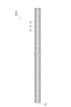
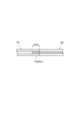
- FIG. 1 is a cross-sectional view along the longitudinal direction of a hollow-core fiber according to a first embodiment.
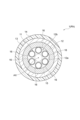
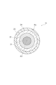
- FIG. 2 is a cross-sectional view perpendicular to the longitudinal direction of the hollow-core fiber of FIG.
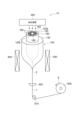
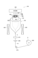
- FIG. 3 is a diagram for explaining a drawing step of the manufacturing method of the hollow core fiber according to the first embodiment.
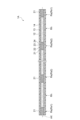
- FIG. 4 is a cross-sectional view along the longitudinal direction of a hollow-core fiber according to the second embodiment.
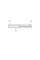
- FIG. 5 is a cross-sectional view of a solid region.
- FIG. 6 is a diagram for explaining the wire drawing process including the solidifying process.
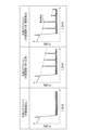
- FIG. 7 is a diagram for explaining a method of detecting an abnormal portion by OTDR measurement.
- FIG. 1 is a cross-sectional view along the longitudinal direction of a hollow-core fiber according to a first embodiment.
- FIG. 2 is a cross-sectional view perpendicular to the longitudinal direction of the hollow-core fiber of FIG.
- FIG. 3 is a
- FIG. 8 is a cross-sectional view of the hollow region of the hollow-core fiber according to the third embodiment.
- FIG. 9 is a cross-sectional view showing a connection portion between the hollow region and a general-purpose optical fiber.
- FIG. 10 is a cross-sectional view showing a connection portion between a solid region and a general-purpose optical fiber.
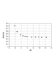
- FIG. 11 is a graph showing the relationship between v and loss at one connection.
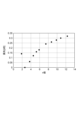
- FIG. 12 is a graph showing the relationship between v and loss for one solid region.
- a method is often used in which a general-purpose optical fiber is connected to both ends of the hollow-core fiber and the ends are sealed.
- Fresnel reflection occurs at the interface between the hollow part of the hollow-core fiber and the solid part of the general-purpose optical fiber.
- the connection loss caused by the difference in mode field diameter can be suppressed by TEC (Thermal Expansion Core) technology, but the effect is limited. For these reasons, sealing with a general-purpose optical fiber causes connection loss and the characteristics of the hollow-core fiber cannot be fully utilized.
- the present disclosure aims to provide a hollow-core fiber capable of propagating light while suppressing the connection loss associated with sealing the ends when connecting general-purpose optical fibers, and a method for manufacturing the hollow-core fiber.
- a hollow-core fiber according to an aspect of the present disclosure includes a hollow region that is a region extending in a longitudinal direction.
- the hollow region includes a glass structure that configures an optical transmission path and has a hollow portion provided therein, and an outer cladding that surrounds the glass structure.
- an average refractive index of the glass structure is n1
- an average refractive index of the outer cladding is n2
- a wavelength of light propagating through the optical transmission path is ⁇
- a relative refractive index difference between the glass structure and the outer cladding is ⁇ shown in formula (1), n1>n2, and a normalized frequency v shown in formula (2) is 2.56 or more.
- the normalized frequency is within the above range, so that the solid region can appropriately relay light. Therefore, light can be propagated while suppressing the influence of cutting.
- the hollow-core fiber of (1) above is a hollow-core fiber further including a solid region that extends in the longitudinal direction, and the solid region has a core made of the same material as the glass structure, and a cladding made of the same material as the outer cladding and surrounding the core, and the area of a cross section perpendicular to the longitudinal direction of the core is the same as the total area of the glass structure, and the area of a cross section perpendicular to the longitudinal direction of the cladding may be the same as the area of a cross section perpendicular to the longitudinal direction of the outer cladding.
- the solid region has a structure equivalent to a structure in which the hollow region is solidified, and therefore light can be propagated while suppressing the effects of cutting.
- a pair of solid regions may be provided at both ends of the hollow region. In this case, it is possible to reliably prevent air, moisture, etc. from entering the hollow region.
- a pair of hollow regions may be provided at both ends of the solid region. In this case, even if air, moisture, etc., enters one of the pair of hollow regions, it is possible to suppress the influence on the other hollow region.
- the solid region may be provided at the end of the hollow-core fiber and connected to an optical fiber having a core and a cladding.
- an optical fiber having a core and a cladding it is possible to ensure connectivity with a so-called general-purpose optical fiber at the end. This also ensures connectivity with connectors, etc.
- the hollow regions and the solid regions may be arranged alternately. In this case, light can be propagated over a long distance while suppressing the effects of cutting.
- the two closest solid regions may be sandwiched between them by a hollow region having a length of 3 km or more and 20 km or less.
- the length of the hollow region is 3 km or more, it is possible to suppress an increase in additional loss.
- the length of the hollow region is 20 km or less, it is possible to suppress a weakening of the effect of the solidification in limiting the region of characteristic degradation in the event of a break.
- the length of the solid region may be 0.5 mm or more. In this case, the solid region can relay light more appropriately.
- the hollow region and the solid region may be arranged coaxially.
- the normalized frequency v may be 11.0 or less.
- the loss per solid point where the hollow-core fiber is solidified can be 0.3 dB or less.
- the normalized frequency v may be 8.0 or less.
- the loss per solid point where the hollow-core fiber is solidified can be 0.25 dB or less.
- the normalized frequency v may be 6.0 or less.
- the loss per solid point where the hollow-core fiber is solidified can be 0.20 dB or less.
- the outer diameter of the solid region may be smaller than the outer diameter of the hollow region.
- the glass structure may include a plurality of inner cladding elements.
- a method for manufacturing a hollow-core fiber according to one aspect of the present disclosure includes a step of melting a longitudinal portion of a glass fiber having a glass structure constituting an optical transmission path with a hollow portion and an outer cladding surrounding the glass structure by heating from a side to solidify the glass fiber. According to the above-described method for manufacturing a hollow-core fiber, a hollow-core fiber having a solid region can be easily manufactured.
- Fig. 1 is a cross-sectional view along the longitudinal direction of the hollow core fiber according to the first embodiment.
- Fig. 2 is a cross-sectional view perpendicular to the longitudinal direction of the hollow core fiber of Fig. 1.
- the hollow core fiber 1 according to the first embodiment has a structure of an anti-resonant hollow core fiber.
- the longitudinal direction of the hollow core fiber 1 is a direction along the central axis AX of the hollow core fiber 1.
- the hollow core fiber 1 includes a hollow region Rh which is a region extending in the longitudinal direction.
- the hollow core fiber 1 includes a hollow region Rh covering the entire region in the longitudinal direction.
- the hollow region Rh includes a glass structure 11, an outer cladding 12, a jacket layer 13, and a resin coating 14. Note that in Fig. 1, the structure of the inner region 12b is omitted.
- the glass structure 11 surrounds a space that becomes the core region 15.
- the core region 15 functions as a hollow optical waveguide region.
- the core region 15 extends along the central axis AX.
- the glass structure 11 functions as an anti-resonance layer that confines light to the center.
- the glass structure 11 is a transmission path component that constitutes an optical transmission path with a hollow portion.
- the glass structure 11 includes a plurality of first inner cladding elements 16.
- the glass structure 11 includes six first inner cladding elements 16.
- the first inner cladding elements 16 are welded at one point to the inner circumferential surface 12a of the outer cladding 12 and are arranged to surround the space that will become the core region 15.
- the first inner cladding elements 16 are arranged spaced apart from one another.
- the first inner cladding elements 16 are arranged spaced apart at equal intervals.
- the first inner cladding elements 16 are thin-walled tubes having a pipe shape extending along the central axis AX.
- the central axes of the first inner cladding elements 16 are arranged offset from the central axis AX.
- the outer cladding 12 surrounds the glass structure 11.
- the outer cladding 12 functions as an optical cladding.
- the outer cladding 12 is a thin-walled tube having a pipe shape extending along the central axis AX.
- the central axis of the outer cladding 12 coincides with the central axis AX.
- the inner surface 12a of the outer cladding 12 defines an internal region 12b that accommodates the glass structure 11.
- the remaining portion of the internal region 12b, excluding the portion occupied by the multiple first inner cladding elements 16, is the hollow portion of the optical transmission path.
- the internal region 12b corresponds to the optical transmission path in which a hollow portion is provided.
- the jacket layer 13 surrounds the outer cladding 12.
- the jacket layer 13 is in contact with the outer peripheral surface of the outer cladding 12.
- the jacket layer 13 covers the outer peripheral surface of the outer cladding 12.
- the jacket layer 13 functions as a physical cladding.
- the resin coating 14 surrounds the jacket layer 13.
- the resin coating 14 is in contact with the outer peripheral surface of the jacket layer 13.
- the resin coating 14 covers the outer peripheral surface of the jacket layer 13.
- the average refractive index of the glass structure 11 is n1
- the average refractive index of the outer cladding 12 is n2, n1>n2.
- the normalized frequency v shown in formula (2) is 2.56 or more and 11.0 or less.
- the total cross-sectional area of the glass structure 11 is the area of only the glass portion, not including the area of the spatial regions between the multiple first inner cladding elements 16 or the area of the spatial regions inside each first inner cladding element 16.
- the normalized frequency v may be 2.56 or more and 6.0 or less. In this case, the loss per solid point can be set to 0.20 dB or less.
- the wavelength is a communication wavelength at which the hollow core fiber 1 is assumed to be used, that is, the wavelength of light propagated by the hollow core fiber 1, and is, for example, 1.55 ⁇ m.
- the method for manufacturing the hollow core fiber 1 includes a drawing process.
- Figure 3 is a diagram for explaining the drawing process of the method for manufacturing the hollow core fiber 1 according to the first embodiment.
- the drawing device 10 shown in FIG. 3 includes a pressure device 300, a heater 400, a resin applicator 500, a winding device 600, and a roller 610.
- the pressure device 300 applies pressure to the inside of the optical fiber preform 100 to be drawn.
- the heater 400 heats one end of the optical fiber preform 100.
- the resin applicator 500 applies resin to the surface of the drawn glass fiber 2 to form the hollow core fiber 1.
- the winding device 600 winds up the hollow core fiber 1.
- the roller 610 adjusts the traveling direction of the hollow core fiber 1.
- the optical fiber preform 100 is composed of an outer cladding portion 120 having a pipe shape and which becomes the outer cladding 12 after drawing, a plurality of first inner cladding element portions 160 having a pipe shape and which become the first inner cladding elements 16 after drawing, and a jacket portion 130 which becomes the jacket layer 13 after drawing.
- each of the plurality of first inner cladding element portions 160 is arranged to surround the center of the outer cladding portion 120 while being in contact with the inner peripheral surface 120a.
- a jacket portion 130 is provided on the outer periphery of the outer cladding portion 120.
- One end of the optical fiber preform 100 is softened by heating using the heater 400.
- the drum of the winding device 600 rotates in the direction indicated by the arrow S, and the hollow glass fiber 2 is pulled out from one end of the optical fiber preform 100.
- pressure control gas or air is supplied by the pressurizing device 300 to the internal space of the outer cladding portion 120 and the internal space of each of the multiple first inner cladding element portions 160, and these internal spaces are pressurized so as not to deform the pipe shape.
- the glass fiber 2 has a glass structure surrounding the space that becomes the core region 15 and corresponding to the glass structure 11, and an outer cladding surrounding the glass structure and corresponding to the outer cladding 12.
- the surface of the glass fiber 2 drawn from the optical fiber preform 100 is coated with resin by a resin coating device 500 to obtain a hollow core fiber 1.
- the obtained hollow core fiber 1 is finally wound onto the drum of a winding device 600 via a roller 610.
- Second Embodiment Fig. 4 is a cross-sectional view along the longitudinal direction of the hollow core fiber according to the second embodiment.
- the hollow core fiber 1A according to the second embodiment is different from the hollow core fiber 1 in that, in addition to the hollow region Rh which is a region extending in the longitudinal direction, the hollow core fiber 1A further includes a solid region Rs which is a region extending in the longitudinal direction.
- the hollow region Rh has the same configuration as the hollow region Rh of the hollow core fiber 1.
- the hollow region Rh and the solid region Rs are provided coaxially. Note that in Fig. 4, the structure of the inner region 12b (see Fig. 2) of the hollow region Rh is omitted.
- Figure 5 is a cross-sectional view of the solid region Rs.
- the solid region Rs includes a core 21, a cladding 22, a jacket layer 23, and a resin coating 24.
- the central axis of the core 21 coincides with the central axis AX.
- the core 21 is made of the same material as the material of the glass structure 11.
- the core 21 is a solid body with no hollow portion.
- the core 21 is formed by melting a glass structure corresponding to the glass structure 11 by heating and solidifying it.
- the area of the cross section perpendicular to the longitudinal direction of the core 21 is the same as the total area of the cross sections perpendicular to the longitudinal direction of the glass structure 11.
- “same” includes cases where they differ within an error range of about ⁇ 5%.
- the cross-sectional area of the core 21 can be determined, for example, from the refractive index profile. That is, the boundary between the core 21 and the cladding 22 is determined as the position where the refractive index gradient is maximum, and then the diameter of the core 21 is determined based on this boundary, thereby obtaining the cross-sectional area of the core 21.
- the total cross-sectional area of the glass structure 11 can be determined, for example, by image analysis of the cross section of the hollow region Rh, or it can be determined from the refractive index profile after the hollow region Rh is solidified by heating.
- the cladding 22 surrounds the core 21.
- the cladding 22 is in contact with the outer peripheral surface of the core 21.
- the cladding 22 covers the outer peripheral surface of the core 21.
- the cladding 22 functions as an optical cladding.
- the cladding 22 is made of the same material as the outer cladding 12.
- the cross-sectional area of the cladding 22 perpendicular to the longitudinal direction is the same as the cross-sectional area of the outer cladding 12 perpendicular to the longitudinal direction.
- “same” includes cases where they differ within an error range of about ⁇ 5%.
- the jacket layer 23 surrounds the clad 22.
- the jacket layer 23 is in contact with the outer peripheral surface of the clad 22.
- the jacket layer 23 covers the outer peripheral surface of the clad 22.
- the jacket layer 23 functions as a physical clad.
- the jacket layer 23 is made of the same material as the jacket layer 13.
- the resin coating 24 surrounds the jacket layer 23.
- the resin coating 24 is in contact with the outer peripheral surface of the jacket layer 23.
- the resin coating 24 covers the outer peripheral surface of the jacket layer 23.
- the resin coating 24 is made of the same material as the resin coating 14.
- the outer diameter of the solid region Rs is smaller than the outer diameter of the hollow region Rh.
- the outer diameter of the hollow region Rh and the outer diameter of the solid region Rs are shown as being equal for simplicity.
- the structure of the solid region Rs keeps the deviation between the mode field diameter (MFD) of the hollow region Rh and the MFD of the solid region Rs below a certain level, suppressing increased loss due to MFD mismatch.
- the hollow region Rh has substantially the same configuration as the solid region Rs.
- the hollow core fiber 1A has multiple hollow regions Rh and multiple solid regions Rs.
- the multiple hollow regions Rh and multiple solid regions Rs are alternately connected along the longitudinal direction.
- the solid regions Rs are provided at intervals of 3 km or more and 20 km or less in the longitudinal direction of the hollow core fiber 1A. If the interval is too short, additional loss increases. If the interval is too long, the effect of the solidification in limiting the area of characteristic degradation in the event of breakage is weakened.
- the distance between a pair of adjacent solid regions Rs sandwiching a hollow region Rh can be said to be 3 km or more and 20 km or less. It can also be said that the two nearest solid regions Rs are provided with a hollow region Rh with a length of 3 km or more and 20 km or less between them. In other words, the longitudinal length of one hollow region Rh is 3 km or more and 20 km or less. The longitudinal length of the solid region Rs is 0.5 mm or more.
- the multiple solid regions Rs include a pair of solid regions Rs1 and one or more solid regions Rs2.
- the pair of solid regions Rs1 are provided at both ends of the hollow core fiber 1A.
- a hollow region Rh is provided at one end of each solid region Rs1.
- an optical fiber having a core and a clad (a so-called general-purpose optical fiber) is connected to the other end of the solid region Rs1.
- a solid region Rs (solid region Rs1 or solid region Rs2) is provided at both ends of each hollow region Rh.
- a hollow region Rh is provided at both ends of the solid region Rs2.
- the solid region Rs2 is provided between the pair of hollow regions Rh.
- the hollow core fiber 1A only needs to have at least a hollow region Rh and a solid region Rs, and the number of hollow regions Rh and the number of solid regions Rs are not limited.
- the hollow core fiber 1A may be composed of, for example, one hollow region Rh and a pair of solid regions Rs1 provided at both ends.
- the method for manufacturing the hollow core fiber 1A differs from the method for manufacturing the hollow core fiber 1 in that the drawing process includes a solidification process.
- Figure 6 is a diagram for explaining the drawing process including the solidification process.
- the drawing apparatus 10A shown in Fig. 6 is different from the drawing apparatus 10 shown in Fig. 3 in that it includes a heat melting device 410.
- the heat melting device 410 heats a part of the hollow glass fiber 2 drawn from the optical fiber preform 100 in the longitudinal direction from the side to solidify it.
- the heat melting device 410 can form intermittently solidified regions in the longitudinal direction of the glass fiber 2.
- the heat melting device 410 heats and melts the glass fiber 2 by, for example, irradiating a CO2 laser.
- the interval and length of the solid region Rs can be adjusted by adjusting the irradiation pattern of the CO2 laser.
- the heat melting device 410 may heat and melt the glass fiber 2 by, for example, irradiating a microwave or arc discharge instead of irradiating a CO2 laser.
- the hollow glass fiber 2 is drawn from one end of the optical fiber preform 100 softened by heating.
- the collapsing process is performed on a portion of the longitudinal direction of the drawn glass fiber 2.
- the heating and melting device 410 melts a portion of the longitudinal direction of the glass fiber 2 from the side by heating to collapsible it.
- the collapsing process is performed by controlling the heating and melting device 410 so that the collapsible regions have a predetermined length and are arranged at intervals of 3 km to 20 km.
- resin is applied to the surface of the glass fiber 2 whose longitudinal portion has been collapsible by the resin application device 500, and the hollow core fiber 1A is obtained.
- the obtained hollow core fiber 1A is finally wound on the drum of the winding device 600 via the roller 610.
- the hollow core fiber 1A has a solid region Rs, even if a break occurs in a part in the longitudinal direction and moisture, CO 2 , or fine dust enters the hollow region Rh from the break, the influence on other hollow regions Rh is suppressed. Therefore, if only the hollow region Rh including the break is discarded, the rest can be used as a product. In the case of a hollow core fiber 1A that has already been laid and used, only the hollow region Rh including the break may be replaced with a new hollow core fiber 1A.
- Figure 7 is a diagram explaining a method for identifying the location of an abnormality in a hollow core fiber.
- the light intensity P detected by an OTDR Optical Time Domain Reflectometer
- the light intensity P of the hollow region is also approximately constant regardless of the distance L.
- the light intensity P of the solid region decreases linearly as the distance L increases.
- Third Embodiment Fig. 8 is a cross-sectional view of the hollow region of the hollow core fiber according to the third embodiment.
- the hollow core fiber 1B according to the third embodiment is different from the hollow core fiber 1 according to the first embodiment and the hollow core fiber 1A according to the second embodiment in that the glass structure 11 has a plurality of second inner cladding elements 17 and a plurality of third inner cladding elements 18.
- the glass structure 11 includes five first inner cladding elements 16, five second inner cladding elements 17, and five third inner cladding elements 18.
- the second inner cladding element 17 is a thin-walled tube having a pipe shape extending along the central axis AX.
- the second inner cladding elements 17 are arranged one by one inside the first inner cladding elements 16.
- the number of the second inner cladding elements 17 is the same as the number of the first inner cladding elements 16.
- the second inner cladding elements 17 are made of, for example, the same material (glass material) as the material of the first inner cladding elements 16.
- the third inner cladding element 18 is a thin-walled tube having a pipe shape extending along the central axis AX.
- the third inner cladding elements 18 are arranged one by one inside the second inner cladding elements 17.
- the number of the third inner cladding elements 18 is the same as the number of the second inner cladding elements 17.
- the third inner cladding elements 18 are made of, for example, the same material (glass material) as the material of the first inner cladding element 16.
- the second inner cladding element 17 and the third inner cladding element 18 are arranged in a state where they are welded to the welded portion between the first inner cladding element 16 and the outer cladding 12.
- the first inner cladding element 16, the second inner cladding element 17, and the third inner cladding element 18 are arranged in a state where they are welded to a common point on the inner circumferential surface 12a of the outer cladding 12.
- the dimensions such as the diameter and thickness of the second inner cladding element 17 and the third inner cladding element 18 are designed to be capable of propagating light in the communication wavelength band with relatively low loss.
- Example 1 As Example 1, a hollow core fiber having a configuration corresponding to the hollow core fiber 1B according to the third embodiment was manufactured. Specifically, a hollow core fiber consisting of only a hollow region was manufactured in the same manner as in the manufacturing method of the hollow core fiber 1 according to the first embodiment. Then, a CO 2 laser was irradiated to the end of the obtained hollow core fiber to form a solid region. The length of the solid region was set to 10 mm.
- the outer diameter of the outer cladding was 150 ⁇ m
- the inner diameter of the outer cladding was 79.7 ⁇ m
- the diameter of the first inner cladding element was 28.1 ⁇ m
- the thickness of the first inner cladding element was 0.5 ⁇ m
- the diameter of the second inner cladding element was 22.6 ⁇ m
- the thickness of the second inner cladding element was 0.5 ⁇ m
- the diameter of the third inner cladding element was 7.6 ⁇ m
- the thickness of the third inner cladding element was 0.5 ⁇ m.
- the total area of the cross section perpendicular to the longitudinal direction of the glass structure was 458.6 ⁇ m 2
- the diameter of a circle having the same area was 24.2 ⁇ m.
- FIG. 9 is a cross-sectional view showing the connection between the hollow region and the general-purpose optical fiber.
- the end of the hollow core fiber 1B of Example 1 before it was solidified was directly connected to the general-purpose optical fiber 60 by fusion.
- FIG. 10 is a cross-sectional view showing the connection between the solid region and the general-purpose optical fiber.
- the end of the hollow core fiber 1B of Example 1 that was solidified was directly connected to the general-purpose optical fiber 60 by fusion.
- the hollow core fiber 1B is indicated with the same reference numerals as in the third embodiment.
- the structure of the internal region of the hollow core fiber 1B is omitted, and the outer cladding, jacket, and resin coating are simply shown as one layer.
- the MFD of the hollow region Rh of the hollow core fiber 1B was 25.0 ⁇ m at a wavelength of 1550 nm, and the MFD of the general-purpose optical fiber 60 was 10.0 ⁇ m at a wavelength of 1550 mm.
- the loss at one connection point was 0.6 dB on average.
- the loss at one connection point changed depending on the v value in equation (2).
- the v value was changed by adjusting the relative refractive index difference ⁇ between the glass structure and the outer cladding.
- Table 1 shows the relative refractive index difference ⁇ [%], v value, and loss [dB] associated with one connection portion in the case of FIG.
- FIG. 11 is a graph showing the relationship between the v value and the loss associated with one connection part.
- the horizontal axis of FIG. 11 shows the v value of hollow core fiber 1B of Example 1.
- the vertical axis of FIG. 11 shows the loss [dB] associated with one connection part in the case of FIG. 10.
- An approximation curve was obtained for the graph of FIG. 11, and the v value at which the approximation curve becomes 0.6 dB was obtained. As a result, it was confirmed that if the v value is 2.56 or more, the loss associated with one connection part can be made smaller than 0.6 dB.
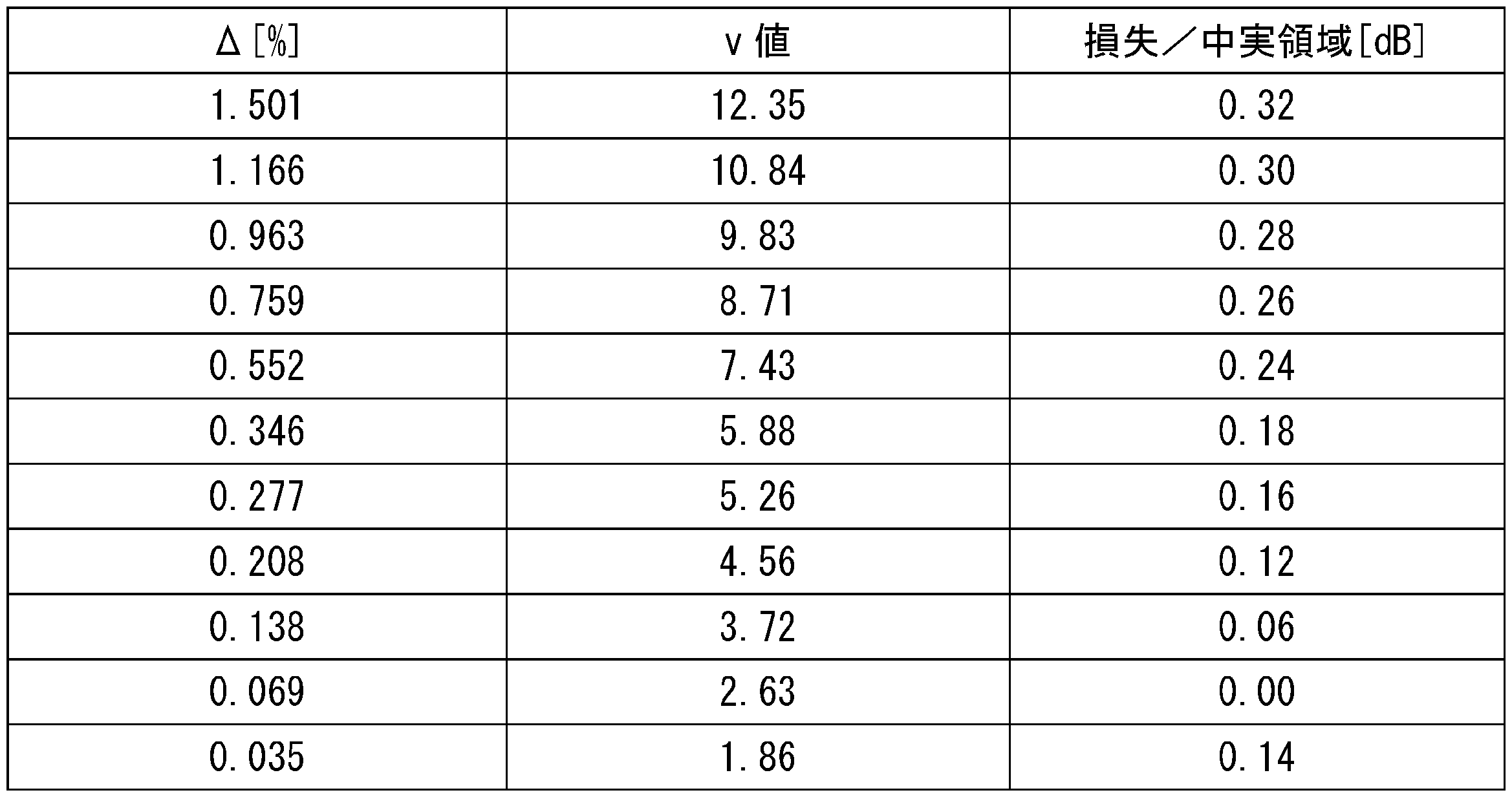
- Example 2 As Example 2, a hollow core fiber having a configuration corresponding to the hollow core fiber 1B according to the third embodiment was manufactured. Specifically, a 50 km long hollow core fiber was manufactured by irradiating a CO2 laser at 5 km intervals during drawing in the same manner as in the manufacturing method of the hollow core fiber 1A according to the second embodiment. The length of the solid region was set to 10 mm. The outer diameter and inner diameter of the outer cladding, the diameter and thickness of the first inner cladding element, the diameter and thickness of the second inner cladding element, the diameter and thickness of the third inner cladding element, and the total area of the cross section perpendicular to the longitudinal direction of the glass structure were set to the same as those of the hollow core fiber according to Example 1. The loss associated with one solid region (solid point) changed depending on the v value of formula (2). The v value was changed by adjusting the relative refractive index difference ⁇ between the glass structure and the outer cladding.
- Table 2 shows the relative refractive index difference ⁇ [%], v value, and loss [dB] for one solid region.
- FIG. 12 is a graph showing the relationship between the v value and the loss associated with one solid region.
- the horizontal axis of FIG. 12 shows the v value of the hollow-core fiber of Example 2.
- the vertical axis of FIG. 12 shows the loss associated with one solid region (loss per solid point) [dB].
- dB loss per solid point
- a portion of the hollow glass fiber 2 in the longitudinal direction drawn out from the optical fiber preform 100 is solidified by the heating and melting device 410, but the glass fibers 2 may also be fused together to form a solid region Rs at the fusion point.
- the hollow region Rh may have a configuration other than that of the above embodiment as long as it has a glass structure 11 that constitutes an optical transmission path with a hollow portion and an outer cladding 12.
- the hollow region Rh may be a photonic crystal hollow core fiber.
Landscapes
- Physics & Mathematics (AREA)
- Optics & Photonics (AREA)
- General Physics & Mathematics (AREA)
- Chemical & Material Sciences (AREA)
- Engineering & Computer Science (AREA)
- Geochemistry & Mineralogy (AREA)
- General Life Sciences & Earth Sciences (AREA)
- Manufacturing & Machinery (AREA)
- Life Sciences & Earth Sciences (AREA)
- Materials Engineering (AREA)
- Organic Chemistry (AREA)
- Crystallography & Structural Chemistry (AREA)
- Optical Fibers, Optical Fiber Cores, And Optical Fiber Bundles (AREA)
- Manufacture, Treatment Of Glass Fibers (AREA)
Abstract
Description


発明者らは、上述の従来技術について検討した結果、以下のような課題を発見した。すなわち、上述の従来技術では、中空コアファイバの端部が開放されたまま放置されると、開放された端部から空孔に大気や水分が侵入する。水分の侵入は、1.38μmの波長帯に損失増をもたらし、大気中の二酸化炭素(CO2)の侵入は、1.55μm帯に損失増をもたらす。大気とともにダストが侵入すると、特に金属粒子等の金属成分はガラスからのハロゲン成分と反応して、腐食性金属ハロゲン化物となり、浸食性、腐食性等を示すようになる。この結果、経時劣化により長期に安定して使用できなくなるおそれがある。
本開示の中空コアファイバによれば、汎用光ファイバの接続による端部の封止に伴う接続損失を抑制しながら、光を伝搬することができる。
最初に本開示の実施態様を列記して説明する。
(1)本開示の一態様に係る中空コアファイバは、長手方向に延びる領域である中空領域を備える。中空領域は、中空部が設けられた、光伝送路を構成するガラス構造体と、ガラス構造体を取り囲む外クラッドと、を有する。ガラス構造体の長手方向に直交する断面の総面積と同じ面積を有する円の直径を2a、ガラス構造体の平均屈折率をn1、外クラッドの平均屈折率をn2、光伝送路を伝搬する光の波長をλ、ガラス構造体と外クラッドとの比屈折率差を式(1)で示されるΔとしたとき、n1>n2であり、式(2)で示される正規化周波数vは、2.56以上である。


上記中空コアファイバの製造方法では、中実領域を備える中空コアファイバを容易に製造することができる。
本実施形態に係る中空コアファイバの具体例を、必要により図面を参照しつつ説明する。なお、本開示はこれらの例示に限定されず、請求の範囲によって示され、請求の範囲と均等の意味および範囲内でのすべての変更が含まれることが意図される。図面の説明において同一の要素には同一の符号を付し、重複する説明を省略する。
図1は、第1実施形態に係る中空コアファイバの長手方向に沿う断面図である。図2は、図1の中空コアファイバの長手方向に直交する断面図である。図1及び図2に示されるように、第1実施形態に係る中空コアファイバ1は、反共振中空コアファイバの構造を有している。中空コアファイバ1の長手方向は、中空コアファイバ1の中心軸AXに沿う方向である。中空コアファイバ1は、長手方向に延びる領域である中空領域Rhを備える。中空コアファイバ1は、長手方向の全領域にわたる中空領域Rhを備える。中空領域Rhは、ガラス構造体11と、外クラッド12と、ジャケット層13と、樹脂被覆14と、を備える。なお、図1では、内部領域12bの構造を省略して示す。


図4は、第2実施形態に係る中空コアファイバの長手方向に沿う断面図である。図4に示されるように、第2実施形態に係る中空コアファイバ1Aは、長手方向に延びる領域である中空領域Rhに加えて、長手方向に延びる領域である中実領域Rsをさらに備える点で、中空コアファイバ1と相違している。中空領域Rhは、中空コアファイバ1の中空領域Rhと同じ構成を有している。中空領域Rhおよび中実領域Rsは、同軸に設けられている。なお、図4では、中空領域Rhの内部領域12b(図2参照)の構造を省略して示す。
図8は、第3実施形態に係る中空コアファイバの中空領域の断面図である。図8に示されるように、第3実施形態に係る中空コアファイバ1Bは、ガラス構造体11が複数の第2内クラッド要素17および複数の第3内クラッド要素18を有している点で、第1実施形態に係る中空コアファイバ1、及び、第2実施形態に係る中空コアファイバ1Aと相違している。図示を省略するが、中空コアファイバ1Bが中実領域Rsを備える場合、中空コアファイバ1Bの中実領域Rsは、中空コアファイバ1Aの中実領域Rsと同等の構造を有している。本実施形態では、ガラス構造体11は、5つの第1内クラッド要素16、5つの第2内クラッド要素17、及び、5つの第3内クラッド要素18を含む。
実施例1として、第3実施形態に係る中空コアファイバ1Bに対応する構成を有する中空コアファイバを製造した。具体的には、第1実施形態に係る中空コアファイバ1の製造方法と同様にして、中空領域のみで構成される中空コアファイバを製造した。その後、得られた中空コアファイバの端部にCO2レーザを照射して中実領域を形成した。中実領域の長さは10mmとした。外クラッドの外径を150μm、外クラッドの内径を79.7μm、第1内クラッド要素の直径を28.1μm、第1内クラッド要素の厚さを0.5μm、第2内クラッド要素の直径を22.6μm、第2内クラッド要素の厚さを0.5μm、第3内クラッド要素の直径を7.6μm、第3内クラッド要素の厚さを0.5μmとした。ガラス構造体の長手方向に直交する断面の総面積は458.6μm2であり、これと同じ面積を有する円の直径は24.2μmであった。

実施例2として、第3実施形態に係る中空コアファイバ1Bに対応する構成を有する中空コアファイバを製造した。具体的には、第2実施形態に係る中空コアファイバ1Aの製造方法と同様にして、線引き中にCO2レーザを5km間隔で照射し、50km長の中空コアファイバを製造した。中実領域の長さは10mmとした。外クラッドの外径及び内径、第1内クラッド要素の直径及び厚さ、第2内クラッド要素の直径及び厚さ、第3内クラッド要素の直径及び厚さ、及び、ガラス構造体の長手方向に直交する断面の総面積は、実施例1に係る中空コアファイバと同様にした。一つの中実領域(中実点)に係る損失は式(2)のv値によって変化した。v値は、ガラス構造体と外クラッドとの比屈折率差Δを調整することで、変化させた。
2…ガラスファイバ
10,10A…線引き装置
11…ガラス構造体
12…外クラッド
12a…内周面
12b…内部領域
13…ジャケット層
14…樹脂被覆
15…コア領域
16…第1内クラッド要素
17…第2内クラッド要素
18…第3内クラッド要素
21…コア
22…クラッド
23…ジャケット層
24…樹脂被覆
60…汎用光ファイバ
100…光ファイバ母材
120…外クラッド部
120a…内周面
120b…内部領域
130…ジャケット部
160…第1内クラッド要素部
300…加圧装置
400…ヒーター
410…加熱溶融装置
500…樹脂塗布装置
600…巻き取り装置
610…ローラー
AX…中心軸
L…距離
P…光強度
Rh…中空領域
Rs,Rs1,Rs2…中実領域
S…矢印
Claims (15)
- 長手方向に延びる領域である中空領域を備える中空コアファイバであって、
前記中空領域は、
中空部が設けられた、光伝送路を構成するガラス構造体と、
前記ガラス構造体を取り囲む外クラッドと、を有し、
前記ガラス構造体の前記長手方向に直交する断面の総面積と同じ面積を有する円の直径を2a、前記ガラス構造体の平均屈折率をn1、前記外クラッドの平均屈折率をn2、前記光伝送路を伝搬する光の波長をλ、前記ガラス構造体と前記外クラッドとの比屈折率差を式(1)で示されるΔとしたとき、n1>n2であり、式(2)で示される正規化周波数vは、2.56以上である、中空コアファイバ。


- 前記長手方向に延びる領域である中実領域をさらに備える中空コアファイバであって、
前記中実領域は、
前記ガラス構造体の材料と同じ材料で構成されるコアと、
前記外クラッドの材料と同じ材料で構成され、前記コアを取り囲むクラッドと、を有し、
前記コアの前記長手方向に直交する断面の面積は、前記ガラス構造体の前記総面積と同じであり、
前記クラッドの前記長手方向に直交する断面の面積は、前記外クラッドの前記長手方向に直交する断面の面積と同じである、
請求項1に記載の中空コアファイバ。 - 一対の前記中実領域が、前記中空領域の両端に設けられている、
請求項2に記載の中空コアファイバ。 - 一対の前記中空領域が、前記中実領域の両端に設けられている、
請求項2または請求項3に記載の中空コアファイバ。 - 前記中実領域は、前記中空コアファイバの端部に設けられ、コア及びクラッドを有する光ファイバと接続されている、
請求項2から請求項4のいずれか一項に記載の中空コアファイバ。 - 複数の前記中空領域及び複数の前記中実領域は、交互に設けられている、
請求項2から請求項5のいずれか一項に記載の中空コアファイバ。 - 最も近い2つの前記中実領域は、3km以上20km以下の長さの前記中空領域を間に挟んで設けられている、
請求項2から請求項6のいずれか一項に記載の中空コアファイバ。 - 前記中実領域の長さは、0.5mm以上である、
請求項2から請求項7のいずれか一項に記載の中空コアファイバ。 - 前記中空領域および前記中実領域は、同軸に設けられている、
請求項2から請求項8のいずれか一項に記載の中空コアファイバ。 - 前記正規化周波数vは、11.0以下である、
請求項2から請求項9のいずれか一項に記載の中空コアファイバ。 - 前記正規化周波数vは、8.0以下である、
請求項2から請求項9のいずれか一項に記載の中空コアファイバ。 - 前記正規化周波数vは、6.0以下である、
請求項2から請求項9のいずれか一項に記載の中空コアファイバ。 - 前記中実領域の外径は、前記中空領域の外径より小さい、
請求項2から請求項12のいずれか一項に記載の中空コアファイバ。 - 前記ガラス構造体は、複数の内クラッド要素を含む、
請求項1から請求項13のいずれか一項に記載の中空コアファイバ。 - 中空部が設けられた光伝送路を構成するガラス構造体と、前記ガラス構造体を取り囲む外クラッドと、を有するガラスファイバの長手方向の一部を側面から加熱により溶融させて中実化する工程を含む、
中空コアファイバの製造方法。
Priority Applications (5)
| Application Number | Priority Date | Filing Date | Title |
|---|---|---|---|
| CN202380072313.5A CN120035779A (zh) | 2022-11-11 | 2023-10-12 | 空芯光纤及空芯光纤的制造方法 |
| EP23888418.3A EP4617738A4 (en) | 2022-11-11 | 2023-10-12 | HOLLOW CORE FIBER AND HOLLOW CORE FIBER MANUFACTURING PROCESS |
| US18/835,066 US20250164688A1 (en) | 2022-11-11 | 2023-10-12 | Hollow-core fiber and method for manufacturing hollow-core fiber |
| JP2024504251A JP7485253B1 (ja) | 2022-11-11 | 2023-10-12 | 中空コアファイバおよび中空コアファイバの製造方法 |
| JP2024069590A JP2024102136A (ja) | 2022-11-11 | 2024-04-23 | 中空コアファイバの製造方法 |
Applications Claiming Priority (2)
| Application Number | Priority Date | Filing Date | Title |
|---|---|---|---|
| JP2022-181193 | 2022-11-11 | ||
| JP2022181193 | 2022-11-11 |
Publications (1)
| Publication Number | Publication Date |
|---|---|
| WO2024101065A1 true WO2024101065A1 (ja) | 2024-05-16 |
Family
ID=91032820
Family Applications (1)
| Application Number | Title | Priority Date | Filing Date |
|---|---|---|---|
| PCT/JP2023/037065 Ceased WO2024101065A1 (ja) | 2022-11-11 | 2023-10-12 | 中空コアファイバおよび中空コアファイバの製造方法 |
Country Status (5)
| Country | Link |
|---|---|
| US (1) | US20250164688A1 (ja) |
| EP (1) | EP4617738A4 (ja) |
| JP (2) | JP7485253B1 (ja) |
| CN (1) | CN120035779A (ja) |
| WO (1) | WO2024101065A1 (ja) |
Families Citing this family (2)
| Publication number | Priority date | Publication date | Assignee | Title |
|---|---|---|---|---|
| CN118795592A (zh) * | 2024-07-23 | 2024-10-18 | 中国移动通信有限公司研究院 | 空芯光纤 |
| CN121386117B (zh) * | 2025-12-24 | 2026-04-28 | 长飞光纤光缆股份有限公司 | 一种空芯和实芯光纤混合光纤束和包含其的光缆 |
Citations (10)
| Publication number | Priority date | Publication date | Assignee | Title |
|---|---|---|---|---|
| JP2002323625A (ja) * | 2001-04-25 | 2002-11-08 | Sumitomo Electric Ind Ltd | 光ファイバの端面部構造および光ファイバ |
| WO2009044100A1 (en) | 2007-10-03 | 2009-04-09 | University Of Bath | Hollow-core photonic crystal fibre |
| JP2017015881A (ja) * | 2015-06-30 | 2017-01-19 | 三菱電線工業株式会社 | 光ファイバ及び導光部材 |
| JP2017052084A (ja) | 2015-07-10 | 2017-03-16 | リープヘル−フェアツァーンテヒニク ゲゼルシャフト ミット ベシュレンクテル ハフツング | 修整された表面形状を有する歯付のワークピースを製造する方法 |
| US20200115270A1 (en) * | 2017-03-14 | 2020-04-16 | Nanyang Technological University | Fiber preform, optical fiber and methods for forming the same |
| WO2020217052A1 (en) | 2019-04-24 | 2020-10-29 | University Of Southampton | Antiresonant hollow core fibre, preform therefor and method of fabrication |
| JP2022502716A (ja) * | 2018-10-03 | 2022-01-11 | ルメニシティ・リミテッド | 光導波路アダプタ組立体 |
| WO2022044891A1 (ja) * | 2020-08-25 | 2022-03-03 | 株式会社ヨコオ | 光ファイバ終端構造、光接続部品および中空コア光ファイバ |
| JP2022541098A (ja) * | 2019-07-17 | 2022-09-22 | ヘレーウス クヴァルツグラース ゲゼルシャフト ミット ベシュレンクテル ハフツング ウント コンパニー コマンディートゲゼルシャフト | 中空コアファイバの製造方法および中空コアファイバ用プリフォームの製造方法 |
| JP2022181193A (ja) | 2021-05-25 | 2022-12-07 | 有限会社横川鉄工所 | 簡易水栓及び簡易手洗い装置 |
Family Cites Families (18)
| Publication number | Priority date | Publication date | Assignee | Title |
|---|---|---|---|---|
| AU2002214944A1 (en) * | 2000-11-10 | 2002-05-21 | Crystal Fibre A/S | Optical fibres with special bending and dispersion properties |
| CA2445487A1 (en) * | 2001-10-09 | 2003-04-17 | Crystal Fibre A/S | Hermetically sealed optical fibre with voids or holes, method of its production, and its use |
| GB0214118D0 (en) * | 2002-06-19 | 2002-07-31 | Blazephotonics Ltd | Improvements in and relating to optical fibres |
| US7321712B2 (en) * | 2002-12-20 | 2008-01-22 | Crystal Fibre A/S | Optical waveguide |
| GB0314485D0 (en) * | 2003-06-20 | 2003-07-23 | Blazephotonics Ltd | Enhanced optical waveguide |
| JP2004325948A (ja) * | 2003-04-25 | 2004-11-18 | Mitsubishi Cable Ind Ltd | 光伝送装置 |
| US7403689B2 (en) * | 2003-11-19 | 2008-07-22 | Corning Incorporated | Active photonic band-gap optical fiber |
| US7280730B2 (en) * | 2004-01-16 | 2007-10-09 | Imra America, Inc. | Large core holey fibers |
| JP4254716B2 (ja) * | 2005-01-27 | 2009-04-15 | 日立電線株式会社 | レーザエネルギー伝送用光ファイバ及びレーザエネルギー伝送方法並びにレーザエネルギー伝送装置 |
| MXGT05000015A (es) * | 2005-11-15 | 2007-05-14 | Vladimir P Minkovich | Fibra optica micro-estructurada adelgazada con transmision selectiva para sensores de fibra optica y metodo para fabricar la misma. |
| US7483615B2 (en) * | 2006-02-27 | 2009-01-27 | Her Majesty The Queen In Right Of Canada As Represented By The Minister Of Industry, Through The Communications Research Centre Canada | Method of changing the refractive index in a region of a core of a photonic crystal fiber using a laser |
| US7496260B2 (en) * | 2007-03-27 | 2009-02-24 | Imra America, Inc. | Ultra high numerical aperture optical fibers |
| US7346250B1 (en) * | 2007-03-30 | 2008-03-18 | Corning Incorporated | Preferential etching method of forming microstructure for an optical waveguide |
| US7660504B2 (en) * | 2007-05-03 | 2010-02-09 | Corning Cable Systems Llc | Connectorized nano-engineered optical fibers and methods of forming same |
| US8285098B2 (en) * | 2009-03-31 | 2012-10-09 | Imra America, Inc. | Wide bandwidth, low loss photonic bandgap fibers |
| JP5679420B2 (ja) * | 2010-09-28 | 2015-03-04 | 株式会社フジクラ | ソリッドフォトニックバンドギャップファイバおよび該ファイバを用いたファイバモジュールおよびファイバアンプ、ファイバレーザ |
| JP5916943B2 (ja) * | 2013-02-26 | 2016-05-11 | 株式会社フジクラ | フォトニックバンドギャップファイバ用母材の製造方法、フォトニックバンドギャップファイバの製造方法、フォトニックバンドギャップファイバ用母材、及び、フォトニックバンドギャップファイバ |
| WO2019013701A1 (en) * | 2017-07-13 | 2019-01-17 | Nanyang Technological University | FIBER PREFORM, OPTICAL FIBER, ASSOCIATED FORMATION METHODS, AND OPTICAL DEVICES HAVING OPTICAL FIBER |
-
2023
- 2023-10-12 JP JP2024504251A patent/JP7485253B1/ja active Active
- 2023-10-12 EP EP23888418.3A patent/EP4617738A4/en active Pending
- 2023-10-12 WO PCT/JP2023/037065 patent/WO2024101065A1/ja not_active Ceased
- 2023-10-12 US US18/835,066 patent/US20250164688A1/en active Pending
- 2023-10-12 CN CN202380072313.5A patent/CN120035779A/zh active Pending
-
2024
- 2024-04-23 JP JP2024069590A patent/JP2024102136A/ja active Pending
Patent Citations (11)
| Publication number | Priority date | Publication date | Assignee | Title |
|---|---|---|---|---|
| JP2002323625A (ja) * | 2001-04-25 | 2002-11-08 | Sumitomo Electric Ind Ltd | 光ファイバの端面部構造および光ファイバ |
| WO2009044100A1 (en) | 2007-10-03 | 2009-04-09 | University Of Bath | Hollow-core photonic crystal fibre |
| JP2017015881A (ja) * | 2015-06-30 | 2017-01-19 | 三菱電線工業株式会社 | 光ファイバ及び導光部材 |
| JP2017052084A (ja) | 2015-07-10 | 2017-03-16 | リープヘル−フェアツァーンテヒニク ゲゼルシャフト ミット ベシュレンクテル ハフツング | 修整された表面形状を有する歯付のワークピースを製造する方法 |
| US20200115270A1 (en) * | 2017-03-14 | 2020-04-16 | Nanyang Technological University | Fiber preform, optical fiber and methods for forming the same |
| JP2022502716A (ja) * | 2018-10-03 | 2022-01-11 | ルメニシティ・リミテッド | 光導波路アダプタ組立体 |
| WO2020217052A1 (en) | 2019-04-24 | 2020-10-29 | University Of Southampton | Antiresonant hollow core fibre, preform therefor and method of fabrication |
| JP2022530426A (ja) * | 2019-04-24 | 2022-06-29 | ユニバーシティ、オブ、サウサンプトン | 反共振中空コアファイバ、そのためのプリフォームおよび製作方法 |
| JP2022541098A (ja) * | 2019-07-17 | 2022-09-22 | ヘレーウス クヴァルツグラース ゲゼルシャフト ミット ベシュレンクテル ハフツング ウント コンパニー コマンディートゲゼルシャフト | 中空コアファイバの製造方法および中空コアファイバ用プリフォームの製造方法 |
| WO2022044891A1 (ja) * | 2020-08-25 | 2022-03-03 | 株式会社ヨコオ | 光ファイバ終端構造、光接続部品および中空コア光ファイバ |
| JP2022181193A (ja) | 2021-05-25 | 2022-12-07 | 有限会社横川鉄工所 | 簡易水栓及び簡易手洗い装置 |
Non-Patent Citations (7)
| Title |
|---|
| DING WEI; WANG YING-YING; GAO SHOU-FEI; WANG MENG-LING; WANG PU: "Recent Progress in Low-Loss Hollow-Core Anti-Resonant Fibers and Their Applications", IEEE JOURNAL OF SELECTED TOPICS IN QUANTUM ELECTRONICS, IEEE, USA, vol. 26, no. 4, 1 July 2020 (2020-07-01), USA, pages 1 - 12, XP011763088, ISSN: 1077-260X, DOI: 10.1109/JSTQE.2019.2957445 * |
| HOSEN MD. SARWAR; KHALEQUE ABDUL; SHAHA KUMARY SUMI RANI; ASHA LUTFUN NAHAR: "Single Polarization Low Loss Highly Birefringent Hollow-Core Antiresonant Fiber", 2022 12TH INTERNATIONAL CONFERENCE ON ELECTRICAL AND COMPUTER ENGINEERING (ICECE), IEEE, 21 December 2022 (2022-12-21), pages 268 - 271, XP034325573, DOI: 10.1109/ICECE57408.2022.10088928 * |
| JEFF HECHT: "Is Nothing Better Than Something?", OPTICS & PHOTONICS NEWS, March 2021 (2021-03-01), pages 28 - 34 |
| See also references of EP4617738A1 |
| VAN PUTTEN LIEKE, FOKOUA ERIC NUMKAM; MOUSAVI SEYEDMOHAMMAD A; BELARDI WALTER; POLETTI FRANCESCO: "Optimizing the Curvature of Elliptical Cladding Elements to Reduce Leakage Loss in Antiresonant Hollow Core Fibres", 42ND EUROPEAN CONFERENCE AND EXHIBITION ON OPTICAL COMMUNICATIONS, 18 September 2016 (2016-09-18), pages 1034 - 1036, XP093171307 * |
| W. BELARDI ET AL.: "Hollow antiresonant fibers with reduced attenuation", OPTICS LETTERS, vol. 39, no. 7, 1 April 2014 (2014-04-01), pages 1853 - 1856, XP001589242, DOI: 10.1364/OL.39.001853 |
| WU DAKUN; YU FEI; LIU YINYAO; LIAO MEISONG: "Dependence of Waveguide Properties of Anti-Resonant Hollow-Core Fiber on Refractive Index of Cladding Material", JOURNAL OF LIGHTWAVE TECHNOLOGY, IEEE, USA, vol. 37, no. 21, 1 November 2019 (2019-11-01), USA, pages 5593 - 5699, XP011756386, ISSN: 0733-8724, DOI: 10.1109/JLT.2019.2934392 * |
Also Published As
| Publication number | Publication date |
|---|---|
| JP7485253B1 (ja) | 2024-05-16 |
| CN120035779A (zh) | 2025-05-23 |
| EP4617738A4 (en) | 2026-03-11 |
| JPWO2024101065A1 (ja) | 2024-05-16 |
| JP2024102136A (ja) | 2024-07-30 |
| EP4617738A1 (en) | 2025-09-17 |
| US20250164688A1 (en) | 2025-05-22 |
Similar Documents
| Publication | Publication Date | Title |
|---|---|---|
| JP7485253B1 (ja) | 中空コアファイバおよび中空コアファイバの製造方法 | |
| JP4666548B2 (ja) | フォトニック結晶ファイバ及びこれに係る改良 | |
| US11960119B2 (en) | Optical waveguide adapter assembly | |
| US6652163B2 (en) | Splice joint and process for joining a microstructured optical fiber and a conventional optical fiber | |
| CN103154790B (zh) | 保偏光纤 | |
| US9529149B2 (en) | Optical fiber microwire devices and manufacture method thereof | |
| US9086538B2 (en) | Method for fusion splicing optical fibers | |
| JP6921021B2 (ja) | 光システムとともに用いられるクラッドモードストリッパー及び同クラッドモードストリッパーを形成する方法 | |
| JP2012513612A (ja) | 2本の光ファイバー間のスプライス接続部及びこの種のスプライス接続部を作製する方法 | |
| JP5117131B2 (ja) | ホーリーファイバおよびホーリーファイバの製造方法 | |
| CN100561263C (zh) | 光子晶体光纤的连接方法以及连接结构 | |
| CN114207490B (zh) | 光纤拼接方法 | |
| JPH07504767A (ja) | 光ファイバ減衰器 | |
| JP7036027B2 (ja) | 光ファイバ線路および光ファイバ線路製造方法 | |
| WO2018061725A1 (ja) | 中間クラッドの屈折率が内部クラッドの屈折率より小さい光ファイバコンバイナ、光ファイバ及びレーザ装置 | |
| US7458734B2 (en) | Method of splicing an optical fiber with holes in the cladding | |
| US20060062533A1 (en) | Photonic crystal fiber, method of manufacturing the crystal fiber, and method of connecting the fiber | |
| CN102257417A (zh) | 两光学纤维间的接头及制造此类接头的方法 | |
| JP2016151651A (ja) | 光ファイバ及び光伝送システム | |
| JP3940069B2 (ja) | フォトニック結晶ファイバの融着接続方法 | |
| CN112513700B (zh) | 光纤线路、模块及光纤线路制造方法 | |
| JP6853291B2 (ja) | レーザ装置の製造方法 | |
| JP2004219890A (ja) | 多孔構造光ファイバとそれを使用した光線入射方法 | |
| JP4225387B2 (ja) | イメージファイバおよびその製造方法 | |
| JPS6234695B2 (ja) |
Legal Events
| Date | Code | Title | Description |
|---|---|---|---|
| WWE | Wipo information: entry into national phase |
Ref document number: 2024504251 Country of ref document: JP |
|
| 121 | Ep: the epo has been informed by wipo that ep was designated in this application |
Ref document number: 23888418 Country of ref document: EP Kind code of ref document: A1 |
|
| WWE | Wipo information: entry into national phase |
Ref document number: 18835066 Country of ref document: US |
|
| WWE | Wipo information: entry into national phase |
Ref document number: 202380072313.5 Country of ref document: CN |
|
| WWP | Wipo information: published in national office |
Ref document number: 18835066 Country of ref document: US |
|
| WWP | Wipo information: published in national office |
Ref document number: 202380072313.5 Country of ref document: CN |
|
| WWE | Wipo information: entry into national phase |
Ref document number: 2023888418 Country of ref document: EP |
|
| NENP | Non-entry into the national phase |
Ref country code: DE |
|
| ENP | Entry into the national phase |
Ref document number: 2023888418 Country of ref document: EP Effective date: 20250611 |
|
| WWP | Wipo information: published in national office |
Ref document number: 2023888418 Country of ref document: EP |