WO2024101261A1 - 切断位置特定システム、及び、切断位置特定方法 - Google Patents
切断位置特定システム、及び、切断位置特定方法 Download PDFInfo
- Publication number
- WO2024101261A1 WO2024101261A1 PCT/JP2023/039559 JP2023039559W WO2024101261A1 WO 2024101261 A1 WO2024101261 A1 WO 2024101261A1 JP 2023039559 W JP2023039559 W JP 2023039559W WO 2024101261 A1 WO2024101261 A1 WO 2024101261A1
- Authority
- WO
- WIPO (PCT)
- Prior art keywords
- imaging device
- cutting position
- carcass
- carcasses
- pair
- Prior art date
- Legal status (The legal status is an assumption and is not a legal conclusion. Google has not performed a legal analysis and makes no representation as to the accuracy of the status listed.)
- Ceased
Links
Images




Classifications
-
- B—PERFORMING OPERATIONS; TRANSPORTING
- B26—HAND CUTTING TOOLS; CUTTING; SEVERING
- B26D—CUTTING; DETAILS COMMON TO MACHINES FOR PERFORATING, PUNCHING, CUTTING-OUT, STAMPING-OUT OR SEVERING
- B26D5/00—Arrangements for operating and controlling machines or devices for cutting, cutting-out, stamping-out, punching, perforating, or severing by means other than cutting
- B26D5/007—Control means comprising cameras, vision or image processing systems
-
- A—HUMAN NECESSITIES
- A22—BUTCHERING; MEAT TREATMENT; PROCESSING POULTRY OR FISH
- A22B—SLAUGHTERING
- A22B5/00—Accessories for use during or after slaughtering
- A22B5/0064—Accessories for use during or after slaughtering for classifying or grading carcasses; for measuring back fat
- A22B5/007—Non-invasive scanning of carcasses, e.g. using image recognition, tomography, X-rays, ultrasound
Definitions
- This disclosure relates to a cutting position identification system and a cutting position identification method.
- Patent Document 1 discloses technology relating to a cutting device and method in the large carcass division process. This document describes how the pair of carcasses to be cut are supported by hanging and supported by support bars extending approximately horizontally from the front and back, thereby fixing the position of the carcasses during cutting.
- One method for identifying the cutting position is to extract characteristic parts of the carcass by analyzing an image obtained by photographing the carcass, and to determine the cutting position based on the extracted characteristic parts. It is expected that the accuracy of extracting characteristic parts from such images can be improved by applying prediction technology using a learning model.
- a learning model can be constructed by preparing training data that teaches the relationship between the image and the characteristic parts, and learning a prediction model using the training data.
- At least one embodiment of the present disclosure has been made in consideration of the above circumstances, and aims to provide a cutting position identification system and a cutting position identification method that can accurately identify the cutting position of a carcass.
- a cutting position specifying system for specifying cutting positions of a pair of carcasses that are cut in half at the spine, comprising: At least one imaging device is arranged on the breast side of the carcass relative to a reference line extending from the spine in a direction perpendicular to the cut surface of the carcass for at least one of the pair of carcasses; an identification device for identifying the cutting position passing through the space between the ribs using an image captured by the at least one imaging device; Equipped with.
- a cutting position specifying method includes: A cutting position specifying method for specifying cutting positions of a pair of carcasses that are cut in half at the spine, comprising: A step of imaging at least one of the pair of carcasses using at least one imaging device arranged on the breast side of the carcass relative to a reference line extending from the spine in a direction perpendicular to the cut surface of the carcass; using the image to identify the cut location passing between the ribs; Equipped with.
- At least one embodiment of the present disclosure provides a cutting position identification system and a cutting position identification method that can accurately identify the cutting position of a carcass.
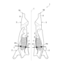
- FIG. 2 is a schematic diagram showing a pair of carcasses from the front.
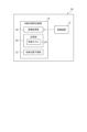
- FIG. 1 is a configuration diagram of a cutting position specifying system according to an embodiment.
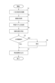
- 3 is a flowchart showing a cut location identification method implemented by the cut location identification system of FIG. 2 .
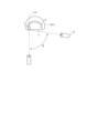
- 1 is a schematic diagram showing an arrangement layout of imaging devices according to a reference technology from above a pair of carcasses.
- FIG. 5 is an example of an image captured by the imaging device of FIG. 4.
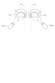
- FIG. 2 is a schematic diagram showing an arrangement layout of imaging devices according to one embodiment, viewed from above a pair of carcasses.
- 7 is an example of an image captured by the imaging device of FIG. 6.
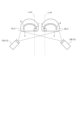
- FIG. 13 is a schematic diagram showing an arrangement layout of imaging devices according to another embodiment, viewed from above a pair of carcasses.
- FIG. 13 is a schematic diagram showing an arrangement layout of imaging devices according to another embodiment, viewed from above a pair of carcasses.
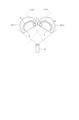
- FIG. 13 is a schematic diagram showing an arrangement layout of imaging devices according to another embodiment, viewed from above a pair of carcasses.
- Figure 1 is a schematic diagram showing a pair of carcasses 1 from the front.
- the pair of carcasses 1 are formed by splitting the meat of a relatively large livestock animal, such as a pig or cow, in half at the vertebrae 7 (backbone).
- the pair of carcasses 1 includes a left carcass 1A and a right carcass 1B.
- Each of the pair of carcasses 1 is arranged symmetrically with respect to the central axis C, with the forebody 2 side facing downward (the hindbody 3 side facing upward), the dorsal side facing inward (the chest side facing outward), and the cut surface 4 on which the vertebrae 7 and ribs 8 are visible facing the viewer.
- the left carcass 1A and the right carcass 1B may have different parts, but in the following explanation they are described as having approximately the same shape.
- Such a pair of carcasses is supported by hanging the legs 5 located at the top of the paper in Figure 1, which are held by a clamping mechanism (not shown).
- the cutting position identification system 10 is a system for identifying a cutting position L for cutting the forepart 2 of a pair of carcasses 1.
- the cutting position L is identified by image analysis using an image captured by an imaging device 12 provided in the cutting position identification system 10.
- the cutting position L is identified by image analysis as a straight line connecting a first characteristic point P1 corresponding to a connection between a specific vertebra and a rib on the dorsal side of the carcass 1 (between the third and fourth connection from the bottom in FIG.
- the method for identifying the cutting position L may be based on other characteristic points extracted by image analysis.
- FIG. 2 is a configuration diagram of the cut position identification system 10 according to one embodiment
- FIG. 3 is a flowchart showing a cut position identification method implemented by the cut position identification system 10 of FIG. 2.
- the cutting position identification system 10 is a system for identifying the cutting position L of a pair of carcasses 1, and includes at least one imaging device 12 and a cutting position identification device 14.
- the imaging device 12 is a device such as a camera that is arranged to face the cut surface 4 of the pair of carcasses 1 and is capable of capturing an image of the pair of carcasses 1.
- the image captured by the imaging device 12 may be a still image or a video.
- the number of imaging devices 12 may be one or more (the specific layout of the imaging devices 12 will be described later).
- the cutting position identification device 14 is a device for identifying the cutting position L of a pair of carcasses 1 using the image captured by the imaging device 12, and is composed of, for example, a CPU (Central Processing Unit), a RAM (Random Access Memory), a ROM (Read Only Memory), and a computer-readable storage medium.
- the series of processes for realizing various functions are stored in the form of a program in a storage medium, for example, and the CPU reads this program into the RAM, etc., and executes information processing and arithmetic processing to realize various functions.
- the program may be installed in a ROM or other storage medium in advance, may be provided in a state stored in a computer-readable storage medium, or may be distributed via wired or wireless communication means.
- Computer-readable storage media include magnetic disks, optical magnetic disks, CD-ROMs, DVD-ROMs, and semiconductor memories.
- the functional configuration of the cutting position identification device 14 provided in the cutting position identification system 10 includes an image acquisition unit 18, a storage unit 20, and a cutting position prediction unit 22.
- the image acquisition unit 18 is a component for acquiring images captured by the imaging device 12.
- the memory unit 20 is configured to store various data necessary for the calculation processing of the cutting position identification device 14, and stores the learning model 24 used to predict the cutting position L.
- the learning model 24 is a prediction model for inputting an image acquired by the image acquisition unit 18 and predicting the cutting position L based on the image, and is trained in advance using teacher data.
- the learning model 24 is trained by specifying a first feature point P1 and a second feature point P2 for identifying the cutting position L in each of a sufficient number of sample images prepared as teacher data.
- the cut position prediction unit 22 is configured to predict the cut position L in the image acquired by the image acquisition unit 18. Specifically, the cut position prediction unit 22 obtains a prediction result of the cut position L by inputting the image acquired by the image acquisition unit 18 to the learning model 24 stored in the storage unit 20. The cut position L predicted by the cut position prediction unit 22 is output as the identification result of the cut position identification device 14.
- step S1 an image of a pair of carcasses 1 is captured by the imaging device 12 (step S1), and the image captured by the imaging device 12 is acquired by the image acquisition unit 18 (step S2).
- the cutting position prediction unit 22 accesses the memory unit 20 to obtain a learning model 24 that has been trained in advance using teacher data (step S3), and predicts the cutting position L by inputting the image acquired in step S2 into the learning model 24 (step S4).
- step S5 It is determined whether the cut position L predicted in step S4 is within a normal range (step S5).
- step S5 for example, the cut position L predicted in step S4 is displayed superimposed on the image acquired in step S2, so that the operator can confirm whether the cut position L predicted in step S4 is within the normal range. If the cut position L is out of the normal range (step S5: NO), the cut position L is corrected by the operator (step S6), and the corrected cut position L is output as the specified result (step S7).
- step S7 the prediction result by the incision position prediction unit 22 is output as it is (step S7).
- Figure 4 is a schematic diagram showing the layout of the imaging device 12 according to the reference technology from above a pair of carcasses 1, and Figure 5 is an example of an image captured by the imaging device 12 of Figure 4.
- the imaging device is placed in front of a pair of carcasses 1 (dorsal to the reference line Lref described below).
- the ribs 8 are curved and connected to the spine 7 on the back side of the paper in FIG. 5. Therefore, in an image captured by the imaging device 12 with the layout of the reference technology, as shown in FIG. 5, the connection 9 between the curved ribs 8 and the spine 7 is difficult to recognize because it is in the blind spot or shadow of the imaging device 12. Therefore, when using a learning model 24 that uses images acquired by the imaging device 12 with the layout shown in FIG. 4 as training data, the prediction accuracy of the cutting position L decreases. According to the inventor's verification, the prediction accuracy was only about 60 to 85%. Such a problem can be solved effectively by the layout of the imaging device 12 described below.
- FIG. 6 is a schematic diagram showing the layout of the imaging device 12 according to one embodiment from above a pair of carcasses 1
- FIG. 7 is an example of an image captured by the imaging device 12 of FIG. 6. Note that in FIG. 6 and FIG. 7, the focus is on the right carcass 1B of the pair of carcasses 1, but unless otherwise specified, the same applies to the left carcass 1A.
- the imaging device 12 is positioned on the chest side of the carcass 1 relative to a reference line Lref that extends from the spine 7 in a direction perpendicular to the cut surface 4 of the carcass 1. This makes it possible to capture an image in which the connection 9 is less likely to be in a blind spot or shadow, compared to when the imaging device 12 is positioned dorsally relative to the reference line Lref as in FIG. 4.
- the imaging device 12 is positioned so that at least a portion of the connection 9 between the spine 7 and the ribs 8 is captured.
- the position of the imaging device 12 is set so that the angle ⁇ , defined as the angle between the reference line Lref and the line segment passing through the spine 7 and the imaging device 12, is in the range of 0 to 80 degrees. This makes it possible to capture an image that reflects at least a portion of the connection part 9.
- the cutting position identification system 10 can accurately identify the cutting position L of the carcass 1 by using a learning model 24 that uses images captured by the imaging device 12 arranged in this manner as training data. According to the inventor's verification, the prediction accuracy can reach 95% or more, and a significant improvement in accuracy was confirmed compared to the reference technology mentioned above.
- FIG. 8 is a schematic diagram showing the layout of the imaging devices 12 according to another embodiment, viewed from above a pair of carcasses 1.
- the cutting position identification system 10 includes multiple imaging devices 12.
- the multiple imaging devices 12 include a first imaging device 12A arranged at a position corresponding to one of the pair of carcasses 1 (left carcass 1A) and a second imaging device 12B arranged at a position corresponding to the other (right carcass 1B).
- the first imaging device 12A is arranged on the chest side of the left carcass 1A relative to the reference line Lref corresponding to the left carcass 1A.
- the second imaging device 12B is arranged on the chest side of the right carcass 1B relative to the reference line Lref corresponding to the right carcass 1B. This allows the two imaging devices 12 to capture images in which the connection parts 9 of each carcass 1 are easily visible, as described above.
- each of the multiple imaging devices 12 is positioned so that the imaging range includes the corresponding carcass 1. That is, the first imaging device 12A is positioned so that its imaging range includes only the left carcass 1A, and the second imaging device 12B is positioned so that its imaging range includes only the right carcass 1B.
- FIG. 9 is a modified example of FIG. 8.
- two imaging devices 12 (first imaging device 12A and second imaging device 12B) are used as in the embodiment shown in FIG. 8, but the first imaging device 12A and the second imaging device 12B are positioned so that they each include a pair of carcasses 1 in their imaging range.
- the first imaging device 12A and the second imaging device 12B are positioned so that both carcasses (left carcass 1A and right carcass 1B) are included in the imaging range of each imaging device.
- FIG. 10 is a schematic diagram showing the layout of the imaging device 12 according to another embodiment from above a pair of carcasses 1.
- the position of the imaging device 12 is the same as that of the above-mentioned reference technique (see FIG. 4), but the gripping angle of the pair of carcasses 1 to be imaged is variable, so that the imaging device 12 is positioned on the chest side of each carcass 1 relative to the reference line Lref.
- the imaging device 12 is positioned on the chest side of each carcass 1 relative to the reference line Lref by changing the position of the imaging device 12 from that of the reference technique, but the imaging device 12 may be positioned on the chest side of each carcass 1 relative to the reference line Lref by changing the position or angle of the carcass 1 to be imaged from that of the reference technique in this way.
- the position or angle of the carcass 1 can be changed by controlling a clamping mechanism (not shown) that grips the carcass 1 .
- the imaging device 12 is a single unit and can be moved relative to the pair of carcasses 1 that are the subject of imaging. Specifically, when the left carcass 1A is the subject of imaging, the imaging device 12 is moved to a position on the left side in FIG. 11, so that the imaging device 12 is positioned so that it is on the chest side of the left carcass 1A relative to the reference line Lref. On the other hand, when the right carcass 1B is the subject of imaging, the imaging device 12 is moved to a position on the right side in FIG.
- the imaging device 12 is positioned so that it is on the chest side of the right carcass 1B relative to the reference line Lref.
- the imaging device 12 may be positioned so that it is on the chest side of each carcass 1 relative to the reference line Lref.
- a cutting position identification system 10 and a cutting position identification method can be realized that can accurately identify the cutting position L using an image captured by an imaging device 12 positioned on the breast side of the carcass 1 relative to a reference line Lref that extends from the spine 7 in a direction perpendicular to the cutting surface 4 of the carcass 1.
- a cutting position specifying system includes: A cutting position specifying system for specifying cutting positions of a pair of carcasses that are cut in half at the spine, comprising: At least one imaging device is arranged on the breast side of the carcass relative to a reference line extending from the spine in a direction perpendicular to the cut surface of the carcass for at least one of the pair of carcasses; an identification device for identifying the cutting position passing through the space between the ribs using an image captured by the at least one imaging device; Equipped with.
- the cutting position on the cutting surface of the carcass is identified using an image captured by an imaging device.
- the imaging device is positioned on the breast side of the carcass relative to a reference line extending from the spine in a direction perpendicular to the cutting surface of the carcass. This makes it possible to capture an image of at least a portion of the connection between the spine and the ribs, which is prone to blind spots or shadows when viewed from the front, or the vicinity thereof.
- the cutting position can be identified with high accuracy based on the positional relationship between the spine and the ribs.
- the at least one imaging device is positioned to image at least a portion of the vertebrae and the rib connection.
- connection between the spine and the ribs is captured in the image captured by the imaging device. Using such an image, the positional relationship between each vertebra that constitutes the spine and the ribs can be clearly recognized, and the cutting position of the carcass can be accurately identified.
- the angle formed by a line segment passing through the spine and the imaging device with respect to the reference line is in the range of 0 to 80 degrees.
- the imaging device by placing the imaging device at a position where the angle is in the range of 0 to 80 degrees, it is possible to preferably capture an image that captures at least a portion of the connection between the spine and the ribs.
- the at least one imaging device A first imaging device arranged at a position corresponding to one of the pair of carcasses; A second imaging device arranged at a position corresponding to the other of the pair of carcasses; including.
- the first imaging device and the second imaging device are positioned so as to include the pair of carcasses in their imaging ranges.
- the positions of the imaging devices may be set so that the imaging range of each imaging device includes both of the pair of carcasses.
- the imaging device can be positioned so that it is closer to the breast side of the carcass than a reference line extending from the spine in a direction perpendicular to the cut surface of the carcass.
- the at least one imaging device is capable of varying a position or angle relative to the carcass.
- the imaging device can be positioned so that it is closer to the breast side of the carcass than a reference line extending from the spine in a direction perpendicular to the cut surface of the carcass.
- the identification device identifies the cutting position based on the image using a learning model that has been trained using the previously acquired images as training data.
- a learning model for predicting the cutting position from an image can be constructed using the results of identifying the cutting position using an image as described above as training data.
- the learning model constructed in this way the cutting position of the carcass can be identified with high accuracy based on the image.
- a cutting position specifying method includes the steps of: A cutting position specifying method for specifying cutting positions of a pair of carcasses that are cut in half at the spine, comprising: A step of imaging at least one of the pair of carcasses using at least one imaging device arranged on the breast side of the carcass relative to a reference line extending from the spine in a direction perpendicular to the cut surface of the carcass; using the image to identify the cut location passing between the ribs; Equipped with.
- the cutting position on the cutting surface of the carcass is identified using an image captured by an imaging device.
- the imaging device is positioned on the breast side of the carcass relative to a reference line extending from the spine in a direction perpendicular to the cutting surface of the carcass. This makes it possible to capture an image of at least a portion of the connection between the spine and the ribs, which is prone to blind spots or shadows when viewed from the front, or the vicinity thereof.
- the cutting position can be identified with high accuracy based on the positional relationship between the spine and the ribs.
- Reference Signs List 1 Carcass 1A Left carcass 1B Right carcass 2 Forepart 3 Hindpart 4 Cutting surface 5 Leg 7 Spine 8 Rib 9 Connection part 10 Cutting position identification system 12 Imaging device 12A First imaging device 12B Second imaging device 14 Cutting position identification device 18 Image acquisition unit 20 Memory unit 22 Cutting position prediction unit 24 Learning model L Cutting position Lref Reference line
Landscapes
- Engineering & Computer Science (AREA)
- Life Sciences & Earth Sciences (AREA)
- Computer Vision & Pattern Recognition (AREA)
- Biophysics (AREA)
- Food Science & Technology (AREA)
- Forests & Forestry (AREA)
- Mechanical Engineering (AREA)
- Details Of Cutting Devices (AREA)
- Processing Of Meat And Fish (AREA)
- Image Analysis (AREA)
- Image Processing (AREA)
Abstract
Description
脊椎の位置で左右に半割りされた一対の枝肉の切断位置を特定するための切断位置特定システムであって、
前記一対の枝肉の少なくとも一方について、前記脊椎から前記枝肉の切断面の直交方向に延ばした基準線よりも前記枝肉の胸側に配置された少なくとも1つの撮像装置と、
前記少なくとも1つの撮像装置で撮像された画像を用いて、前記肋骨間を通る前記切断位置を特定するための特定装置と、
を備える。
脊椎の位置で左右に半割りされた一対の枝肉の切断位置を特定するための切断位置特定方法であって、
前記一対の枝肉の少なくとも一方について、前記脊椎から前記枝肉の切断面の直交方向に延ばした基準線よりも前記枝肉の胸側に配置された少なくとも1つの撮像装置を用いて撮像する工程と、
前記画像を用いて、前記肋骨間を通る前記切断位置を特定する工程と、
を備える。
尚、切断位置Lが正常範囲内である場合には(ステップS5:YES)、切断位置予測部22による予測結果がそのまま出力される(ステップS7)。
尚、枝肉1の位置又は角度の変更は、枝肉1を把持する不図示のクランプ機構を制御することにより実現可能である。
脊椎の位置で左右に半割りされた一対の枝肉の切断位置を特定するための切断位置特定システムであって、
前記一対の枝肉の少なくとも一方について、前記脊椎から前記枝肉の切断面の直交方向に延ばした基準線よりも前記枝肉の胸側に配置された少なくとも1つの撮像装置と、
前記少なくとも1つの撮像装置で撮像された画像を用いて、前記肋骨間を通る前記切断位置を特定するための特定装置と、
を備える。
前記少なくとも1つの撮像装置は、前記脊椎及び前記肋骨の接続部の少なくとも一部が映り込むように配置される。
前記基準線に対して、前記脊椎及び前記撮像装置を通る線分がなす角度は、0~80度の範囲である。
前記少なくとも1つの撮像装置は、
前記一対の枝肉の一方に対応する位置に配置された第1撮像装置と、
前記一対の枝肉の他方に対応する位置に配置された第2撮像装置と、
を含む。
前記第1撮像装置及び前記第2撮像装置は、それぞれ前記一対の枝肉を撮像範囲に含むように配置される。
前記一対の枝肉の把持角度が可変である。
前記少なくとも1つの撮像装置は、前記枝肉に対して相対的な位置又は角度が可変である。
前記特定装置は、過去に取得した前記画像を教師データとして学習した学習モデルを用いて、前記画像に基づいて前記切断位置を特定する。
脊椎の位置で左右に半割りされた一対の枝肉の切断位置を特定するための切断位置特定方法であって、
前記一対の枝肉の少なくとも一方について、前記脊椎から前記枝肉の切断面の直交方向に延ばした基準線よりも前記枝肉の胸側に配置された少なくとも1つの撮像装置を用いて撮像する工程と、
前記画像を用いて、前記肋骨間を通る前記切断位置を特定する工程と、
を備える。
1A 左枝肉
1B 右枝肉
2 前躯
3 後躯
4 切断面
5 脚部
7 脊椎
8 肋骨
9 接続部
10 切断位置特定システム
12 撮像装置
12A 第1撮像装置
12B 第2撮像装置
14 切断位置特定装置
18 画像取得部
20 記憶部
22 切断位置予測部
24 学習モデル
L 切断位置
Lref 基準線
Claims (9)
- 脊椎の位置で左右に半割りされた一対の枝肉の切断位置を特定するための切断位置特定システムであって、
前記一対の枝肉の少なくとも一方について、前記脊椎から前記枝肉の切断面の直交方向に延ばした基準線よりも前記枝肉の胸側に配置された少なくとも1つの撮像装置と、
前記少なくとも1つの撮像装置で撮像された画像を用いて、前記肋骨間を通る前記切断位置を特定するための特定装置と、
を備える、切断位置特定システム。 - 前記少なくとも1つの撮像装置は、前記脊椎及び前記肋骨の接続部の少なくとも一部が映り込むように配置される、請求項1に記載の切断位置特定システム。
- 前記基準線に対して、前記脊椎及び前記撮像装置を通る線分がなす角度は、0~80度の範囲である、請求項1又は2に記載の切断位置特定システム。
- 前記少なくとも1つの撮像装置は、
前記一対の枝肉の一方に対応する位置に配置された第1撮像装置と、
前記一対の枝肉の他方に対応する位置に配置された第2撮像装置と、
を含む、請求項1又は2に記載の切断位置特定システム。 - 前記第1撮像装置及び前記第2撮像装置は、それぞれ前記一対の枝肉を撮像範囲に含むように配置される、請求項4に記載の切断位置特定システム。
- 前記一対の枝肉の把持角度が可変である、請求項1又は2に記載の切断位置特定システム。
- 前記少なくとも1つの撮像装置は、前記枝肉に対して相対的な位置又は角度が可変である、請求項1又は2に記載の切断位置特定システム。
- 前記特定装置は、過去に取得した前記画像を教師データとして学習した学習モデルを用いて、前記画像に基づいて前記切断位置を特定する、請求項1又は2に記載の切断位置特定システム。
- 脊椎の位置で左右に半割りされた一対の枝肉の切断位置を特定するための切断位置特定方法であって、
前記一対の枝肉の少なくとも一方について、前記脊椎から前記枝肉の切断面の直交方向に延ばした基準線よりも前記枝肉の胸側に配置された少なくとも1つの撮像装置を用いて撮像する工程と、
前記画像を用いて、前記肋骨間を通る前記切断位置を特定する工程と、
を備える、切断位置特定方法。
Priority Applications (1)
| Application Number | Priority Date | Filing Date | Title |
|---|---|---|---|
| EP23888609.7A EP4573913A4 (en) | 2022-11-08 | 2023-11-02 | CUTTING POSITION IDENTIFICATION SYSTEM AND CUTTING POSITION IDENTIFICATION METHOD |
Applications Claiming Priority (2)
| Application Number | Priority Date | Filing Date | Title |
|---|---|---|---|
| JP2022-178775 | 2022-11-08 | ||
| JP2022178775A JP2024068382A (ja) | 2022-11-08 | 2022-11-08 | 切断位置特定システム、及び、切断位置特定方法 |
Publications (1)
| Publication Number | Publication Date |
|---|---|
| WO2024101261A1 true WO2024101261A1 (ja) | 2024-05-16 |
Family
ID=91032929
Family Applications (1)
| Application Number | Title | Priority Date | Filing Date |
|---|---|---|---|
| PCT/JP2023/039559 Ceased WO2024101261A1 (ja) | 2022-11-08 | 2023-11-02 | 切断位置特定システム、及び、切断位置特定方法 |
Country Status (3)
| Country | Link |
|---|---|
| EP (1) | EP4573913A4 (ja) |
| JP (1) | JP2024068382A (ja) |
| WO (1) | WO2024101261A1 (ja) |
Cited By (1)
| Publication number | Priority date | Publication date | Assignee | Title |
|---|---|---|---|---|
| WO2026070671A1 (ja) * | 2024-09-30 | 2026-04-02 | 株式会社前川製作所 | 食肉加工システム、及び、食肉加工方法 |
Citations (4)
| Publication number | Priority date | Publication date | Assignee | Title |
|---|---|---|---|---|
| JP2013031916A (ja) | 2011-06-30 | 2013-02-14 | Mayekawa Mfg Co Ltd | 枝肉の分割方法及び装置 |
| WO2018167089A1 (en) * | 2017-03-13 | 2018-09-20 | Carometec A/S | 3d imaging system and method of imaging carcasses |
| WO2020218513A1 (ja) * | 2019-04-26 | 2020-10-29 | 株式会社前川製作所 | 特徴点の認識システムおよび認識方法 |
| JP2022530772A (ja) * | 2019-05-03 | 2022-07-01 | マレル・ミート・ベスローテン・フェンノートシャップ | 吊るされた半身の豚の枝肉からの前端の切断 |
Family Cites Families (2)
| Publication number | Priority date | Publication date | Assignee | Title |
|---|---|---|---|---|
| FR2694479B1 (fr) * | 1992-08-05 | 1994-10-07 | Sydel | Equipement d'abattoir pour prendre des repères sur une carcasse. |
| DE202013002484U1 (de) * | 2013-03-15 | 2014-06-17 | Csb-System Ag | Vorrichtung zur volumetrischen Vermessung eines Schlachttierkörperobjekts |
-
2022
- 2022-11-08 JP JP2022178775A patent/JP2024068382A/ja active Pending
-
2023
- 2023-11-02 WO PCT/JP2023/039559 patent/WO2024101261A1/ja not_active Ceased
- 2023-11-02 EP EP23888609.7A patent/EP4573913A4/en active Pending
Patent Citations (4)
| Publication number | Priority date | Publication date | Assignee | Title |
|---|---|---|---|---|
| JP2013031916A (ja) | 2011-06-30 | 2013-02-14 | Mayekawa Mfg Co Ltd | 枝肉の分割方法及び装置 |
| WO2018167089A1 (en) * | 2017-03-13 | 2018-09-20 | Carometec A/S | 3d imaging system and method of imaging carcasses |
| WO2020218513A1 (ja) * | 2019-04-26 | 2020-10-29 | 株式会社前川製作所 | 特徴点の認識システムおよび認識方法 |
| JP2022530772A (ja) * | 2019-05-03 | 2022-07-01 | マレル・ミート・ベスローテン・フェンノートシャップ | 吊るされた半身の豚の枝肉からの前端の切断 |
Non-Patent Citations (1)
| Title |
|---|
| See also references of EP4573913A4 |
Cited By (1)
| Publication number | Priority date | Publication date | Assignee | Title |
|---|---|---|---|---|
| WO2026070671A1 (ja) * | 2024-09-30 | 2026-04-02 | 株式会社前川製作所 | 食肉加工システム、及び、食肉加工方法 |
Also Published As
| Publication number | Publication date |
|---|---|
| EP4573913A4 (en) | 2025-12-24 |
| JP2024068382A (ja) | 2024-05-20 |
| EP4573913A1 (en) | 2025-06-25 |
Similar Documents
| Publication | Publication Date | Title |
|---|---|---|
| US10445566B2 (en) | Image processing apparatus, image processing method, and non-transitory recording medium storing computer readable program | |
| CN110705405A (zh) | 目标标注的方法及装置 | |
| US12475739B2 (en) | Autonomous livestock monitoring | |
| Guzhva et al. | Feasibility study for the implementation of an automatic system for the detection of social interactions in the waiting area of automatic milking stations by using a video surveillance system | |
| JP2014106692A5 (ja) | ||
| CN104395930B (zh) | 用于定位脊柱的方法、设备和系统 | |
| JP2020183876A (ja) | 特徴点認識システムおよびワーク処理システム | |
| JP6981531B2 (ja) | 物体同定装置、物体同定システム、物体同定方法およびコンピュータプログラム | |
| RU2019103487A (ru) | Автоматизированный контроль качества покраски летательных аппаратов | |
| CN111008560A (zh) | 一种牲畜的重量确定方法、装置、终端及计算机存储介质 | |
| WO2016023075A1 (en) | 3d imaging | |
| US20190244350A1 (en) | Method of and apparatus for diagnosing leg pathologies in quadrupeds | |
| CN108875709B (zh) | 一种扎堆行为检测方法、装置、电子设备及存储介质 | |
| JP2009542293A (ja) | 後続するスキャン間で、スキャン形状をトランスファするための方法、装置、システム及びコンピュータプログラム | |
| JP2024068382A (ja) | 切断位置特定システム、及び、切断位置特定方法 | |
| CN116580078A (zh) | 动物姿态群体估重方法、装置、设备及存储介质 | |
| WO2019045089A1 (ja) | 情報処理装置、長さ測定システム、長さ測定方法およびプログラム記憶媒体 | |
| CN101009755B (zh) | 带水印图像的生成装置及方法、和分析装置 | |
| WO2024101260A1 (ja) | 把持位置特定システム、枝肉切断システム、及び、把持位置特定方法 | |
| CN113532616A (zh) | 基于计算机视觉的体重估计方法、装置及系统 | |
| CN112017148A (zh) | 一种单节骨骼轮廓的提取方法及装置 | |
| JP2025104742A (ja) | 食肉用のカットポイント決定システム、カットポイント決定方法、及び、カットポイント決定プログラム | |
| CN111951233B (zh) | 一种鱼刺残留检测方法及系统 | |
| JPWO2021117347A5 (ja) | ||
| CN112784713A (zh) | 一种基于图像的猪体重估测方法、系统、设备及存储介质 |
Legal Events
| Date | Code | Title | Description |
|---|---|---|---|
| 121 | Ep: the epo has been informed by wipo that ep was designated in this application |
Ref document number: 23888609 Country of ref document: EP Kind code of ref document: A1 |
|
| WWE | Wipo information: entry into national phase |
Ref document number: 2023888609 Country of ref document: EP |
|
| ENP | Entry into the national phase |
Ref document number: 2023888609 Country of ref document: EP Effective date: 20250318 |
|
| NENP | Non-entry into the national phase |
Ref country code: DE |
|
| WWP | Wipo information: published in national office |
Ref document number: 2023888609 Country of ref document: EP |