WO2024106122A1 - 圧縮装置 - Google Patents
圧縮装置 Download PDFInfo
- Publication number
- WO2024106122A1 WO2024106122A1 PCT/JP2023/037691 JP2023037691W WO2024106122A1 WO 2024106122 A1 WO2024106122 A1 WO 2024106122A1 JP 2023037691 W JP2023037691 W JP 2023037691W WO 2024106122 A1 WO2024106122 A1 WO 2024106122A1
- Authority
- WO
- WIPO (PCT)
- Prior art keywords
- temperature
- roll
- lubricating oil
- target
- bearing
- Prior art date
- Legal status (The legal status is an assumption and is not a legal conclusion. Google has not performed a legal analysis and makes no representation as to the accuracy of the status listed.)
- Ceased
Links
Images


Classifications
-
- H—ELECTRICITY
- H01—ELECTRIC ELEMENTS
- H01M—PROCESSES OR MEANS, e.g. BATTERIES, FOR THE DIRECT CONVERSION OF CHEMICAL ENERGY INTO ELECTRICAL ENERGY
- H01M4/00—Electrodes
- H01M4/02—Electrodes composed of, or comprising, active material
- H01M4/04—Processes of manufacture in general
- H01M4/043—Processes of manufacture in general involving compressing or compaction
- H01M4/0435—Rolling or calendering
-
- B—PERFORMING OPERATIONS; TRANSPORTING
- B21—MECHANICAL METAL-WORKING WITHOUT ESSENTIALLY REMOVING MATERIAL; PUNCHING METAL
- B21B—ROLLING OF METAL
- B21B27/00—Rolls, roll alloys or roll fabrication; Lubricating, cooling or heating rolls while in use
- B21B27/06—Lubricating, cooling or heating rolls
- B21B27/08—Lubricating, cooling or heating rolls internally
-
- B—PERFORMING OPERATIONS; TRANSPORTING
- B21—MECHANICAL METAL-WORKING WITHOUT ESSENTIALLY REMOVING MATERIAL; PUNCHING METAL
- B21B—ROLLING OF METAL
- B21B31/00—Rolling stand structures; Mounting, adjusting, or interchanging rolls, roll mountings, or stand frames
- B21B31/07—Adaptation of roll neck bearings
- B21B31/076—Cooling; Lubricating roller bearings
-
- F—MECHANICAL ENGINEERING; LIGHTING; HEATING; WEAPONS; BLASTING
- F16—ENGINEERING ELEMENTS AND UNITS; GENERAL MEASURES FOR PRODUCING AND MAINTAINING EFFECTIVE FUNCTIONING OF MACHINES OR INSTALLATIONS; THERMAL INSULATION IN GENERAL
- F16C—SHAFTS; FLEXIBLE SHAFTS; ELEMENTS OR CRANKSHAFT MECHANISMS; ROTARY BODIES OTHER THAN GEARING ELEMENTS; BEARINGS
- F16C13/00—Rolls, drums, discs, or the like; Bearings or mountings therefor
- F16C13/02—Bearings
-
- F—MECHANICAL ENGINEERING; LIGHTING; HEATING; WEAPONS; BLASTING
- F16—ENGINEERING ELEMENTS AND UNITS; GENERAL MEASURES FOR PRODUCING AND MAINTAINING EFFECTIVE FUNCTIONING OF MACHINES OR INSTALLATIONS; THERMAL INSULATION IN GENERAL
- F16C—SHAFTS; FLEXIBLE SHAFTS; ELEMENTS OR CRANKSHAFT MECHANISMS; ROTARY BODIES OTHER THAN GEARING ELEMENTS; BEARINGS
- F16C37/00—Cooling of bearings
- F16C37/007—Cooling of bearings of rolling bearings
-
- F—MECHANICAL ENGINEERING; LIGHTING; HEATING; WEAPONS; BLASTING
- F16—ENGINEERING ELEMENTS AND UNITS; GENERAL MEASURES FOR PRODUCING AND MAINTAINING EFFECTIVE FUNCTIONING OF MACHINES OR INSTALLATIONS; THERMAL INSULATION IN GENERAL
- F16N—LUBRICATING
- F16N39/00—Arrangements for conditioning of lubricants in the lubricating system
- F16N39/02—Arrangements for conditioning of lubricants in the lubricating system by cooling
-
- F—MECHANICAL ENGINEERING; LIGHTING; HEATING; WEAPONS; BLASTING
- F16—ENGINEERING ELEMENTS AND UNITS; GENERAL MEASURES FOR PRODUCING AND MAINTAINING EFFECTIVE FUNCTIONING OF MACHINES OR INSTALLATIONS; THERMAL INSULATION IN GENERAL
- F16N—LUBRICATING
- F16N39/00—Arrangements for conditioning of lubricants in the lubricating system
- F16N39/04—Arrangements for conditioning of lubricants in the lubricating system by heating
-
- B—PERFORMING OPERATIONS; TRANSPORTING
- B21—MECHANICAL METAL-WORKING WITHOUT ESSENTIALLY REMOVING MATERIAL; PUNCHING METAL
- B21B—ROLLING OF METAL
- B21B27/00—Rolls, roll alloys or roll fabrication; Lubricating, cooling or heating rolls while in use
- B21B27/06—Lubricating, cooling or heating rolls
- B21B27/08—Lubricating, cooling or heating rolls internally
- B21B2027/083—Lubricating, cooling or heating rolls internally cooling internally
-
- B—PERFORMING OPERATIONS; TRANSPORTING
- B21—MECHANICAL METAL-WORKING WITHOUT ESSENTIALLY REMOVING MATERIAL; PUNCHING METAL
- B21B—ROLLING OF METAL
- B21B27/00—Rolls, roll alloys or roll fabrication; Lubricating, cooling or heating rolls while in use
- B21B27/06—Lubricating, cooling or heating rolls
- B21B27/08—Lubricating, cooling or heating rolls internally
- B21B2027/086—Lubricating, cooling or heating rolls internally heating internally
-
- F—MECHANICAL ENGINEERING; LIGHTING; HEATING; WEAPONS; BLASTING
- F16—ENGINEERING ELEMENTS AND UNITS; GENERAL MEASURES FOR PRODUCING AND MAINTAINING EFFECTIVE FUNCTIONING OF MACHINES OR INSTALLATIONS; THERMAL INSULATION IN GENERAL
- F16N—LUBRICATING
- F16N2210/00—Applications
- F16N2210/14—Bearings
-
- F—MECHANICAL ENGINEERING; LIGHTING; HEATING; WEAPONS; BLASTING
- F16—ENGINEERING ELEMENTS AND UNITS; GENERAL MEASURES FOR PRODUCING AND MAINTAINING EFFECTIVE FUNCTIONING OF MACHINES OR INSTALLATIONS; THERMAL INSULATION IN GENERAL
- F16N—LUBRICATING
- F16N2250/00—Measuring
- F16N2250/08—Temperature
-
- Y—GENERAL TAGGING OF NEW TECHNOLOGICAL DEVELOPMENTS; GENERAL TAGGING OF CROSS-SECTIONAL TECHNOLOGIES SPANNING OVER SEVERAL SECTIONS OF THE IPC; TECHNICAL SUBJECTS COVERED BY FORMER USPC CROSS-REFERENCE ART COLLECTIONS [XRACs] AND DIGESTS
- Y02—TECHNOLOGIES OR APPLICATIONS FOR MITIGATION OR ADAPTATION AGAINST CLIMATE CHANGE
- Y02E—REDUCTION OF GREENHOUSE GAS [GHG] EMISSIONS, RELATED TO ENERGY GENERATION, TRANSMISSION OR DISTRIBUTION
- Y02E60/00—Enabling technologies; Technologies with a potential or indirect contribution to GHG emissions mitigation
- Y02E60/10—Energy storage using batteries
Definitions
- This disclosure relates to a compression device.
- the compression device of Patent Document 1 includes a compression roll that compresses the electrode plates, a number of bearings that support both ends of the compression roll, a lubricant temperature adjustment means that adjusts the temperature of the lubricant supplied to each bearing, a number of temperature sensors that detect the surface temperatures of the center and both ends of the compression roll, and a control means that controls the lubricant temperature adjustment means based on the detection values of the multiple temperature sensors.
- the control means controls the lubricant temperature adjustment means so that the surface temperature of the center of the compression roll and the surface temperatures of both ends of the compression roll match each other.
- the compression device includes a compression roll having a roll body and a shaft, the roll body compressing a battery plate, a circulating oil-supplying bearing rotatably supporting the shaft, and a temperature control device connected to the bearing via a pipe and controlling the temperature of the bearing by supplying temperature-adjusted lubricating oil to the bearing, the temperature control device being configured to adjust the temperature of the lubricating oil so that the difference between the temperature of the lubricating oil and a target oil temperature determined based on a roll center temperature, which is the temperature of the central region of the roll body, is equal to or less than a first threshold value.
- the compression device includes a compression roll having a roll body and a shaft, the roll body compressing battery plates, a circulating oil-supplying bearing rotatably supporting the shaft, and a temperature control device connected to the bearing via a pipe and controlling the temperature of the bearing by supplying temperature-adjusted lubricating oil to the bearing, the temperature control device being configured to adjust the temperature of the lubricating oil so that the difference between the temperature of the shaft or the bearing and a target oil temperature determined based on the roll center temperature, which is the temperature of the central region of the roll body, is equal to or less than a second threshold value.
- FIG. 1 is a configuration diagram illustrating a compression device according to a first embodiment.
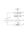
- FIG. 3 is a flowchart showing a method for controlling the temperature of lubricating oil according to the first embodiment.
- FIG. 11 is a configuration diagram illustrating a compression device according to a second embodiment.
- 10 is a flowchart showing a method for controlling the temperature of lubricating oil according to a second embodiment.
- a compression device is a device for compressing battery electrodes (hereinafter also simply referred to as electrodes), and includes a compression roll, a bearing, and a temperature control device.
- the batteries include primary batteries such as lithium primary batteries, and secondary batteries such as alkaline storage batteries (nickel-metal hydride batteries, nickel-cadmium batteries, etc.), lithium-ion secondary batteries, lithium metal secondary batteries, and all-solid-state batteries that include a solid electrolyte.
- the category of secondary batteries also includes power storage devices (e.g., lithium-ion capacitors) in which at least one of the positive and negative electrodes is an electrode that develops capacity through a Faraday reaction.
- the compression roll has a roll body and a shaft, and compresses the battery plate with the roll body.
- the roll body may be supported by the shaft.
- the plate may have a coated part where an active material layer is formed on the surface of the substrate (current collector plate), and a foil exposed part (uncoated part) where no active material layer is formed on the surface of the substrate.
- the compression roll may compress the coated part of the plate with the roll body.
- the compression roll may have a pair of rolls arranged at a predetermined interval. The compression roll may be configured to compress the uncoated part of the plate in addition to the coated part of the plate.
- a plate having an active material layer formed by intermittently applying a composite slurry to a substrate is compressed with the compression roll, the uncoated part of the plate is compressed.
- This type of plate has coated parts intermittently formed in the longitudinal direction of the substrate, and the uncoated parts between adjacent coated parts are compressed by the compression roll.
- the temperature control device is connected to the bearing via piping.
- the temperature control device controls the temperature of the bearing by supplying temperature-adjusted lubricating oil to the bearing.
- the temperature control device may have a heating section for heating the lubricating oil and a cooling section for cooling the lubricating oil.
- the heating section may have, for example, a resistance heater for heating the lubricating oil.
- the cooling section may have, for example, a refrigerant evaporator for cooling the lubricating oil.
- the temperature control device may also have a circulation device (e.g., a pump) for circulating the lubricating oil.
- the temperature control device is configured to adjust the temperature of the lubricating oil so that the difference between the temperature of the lubricating oil and a target oil temperature determined based on the roll center temperature, which is the temperature of the central region of the roll body, is equal to or less than a first threshold value.
- the temperature of the lubricating oil may be the temperature of the lubricating oil flowing out of the temperature control device, may be the temperature of the lubricating oil flowing into the temperature control device, or may be the temperature of the lubricating oil at other points in the circulation path of the lubricating oil.
- the central region of the roll body refers to a region within 50% of the center in the longitudinal direction (or axial direction) of the roll body.
- the central region of the roll body is a region in contact with the electrode plate.
- the target oil temperature may be the roll center temperature or may be a temperature obtained by adding a predetermined value (any positive or negative value) to the roll center temperature.
- the first threshold value may be, for example, 0.2°C or more and 0.5°C or less.
- the temperature of the shaft portion becomes approximately the same as the temperature of the roll body portion due to the heating or cooling action of the lubricating oil flowing through the bearings. In other words, the temperature becomes approximately uniform throughout the compression roll. This makes it possible to suppress the occurrence of thermal crown.
- the target oil temperature is a temperature obtained by adding a predetermined value to the roll center temperature
- the heating or cooling action of the lubricating oil flowing through the bearings creates a difference between the temperature of the shaft portion and the temperature of the roll body portion that corresponds to a predetermined value. This makes it possible to generate the desired thermal crown. For example, by slightly expanding the central region of the roll body portion, it is possible to form the portion of the plate that comes into contact with the central region thinner than the other portions.
- the temperature control device may be configured to adjust the temperature of the lubricating oil to the first target temperature when the difference between the roll center temperature and the first target temperature (hereinafter also referred to as the first temperature deviation) is equal to or less than a first threshold value, and to adjust the temperature of the lubricating oil to a second target temperature obtained by adding the difference between the roll center temperature and the first target temperature (the first temperature deviation) to the first target temperature when the difference between the roll center temperature and the first target temperature (the first temperature deviation) exceeds the first threshold value.
- the occurrence of thermal crown can be sufficiently suppressed by the lubricating oil temperature-adjusted to the first target temperature.
- the temperature of the lubricant is adjusted to a second target temperature obtained by adding the first temperature deviation to the first target temperature, thereby reducing the difference between the roll center temperature and the lubricant temperature, and thus reducing the temperature gradient inside the compression roll. This makes it possible to sufficiently suppress the occurrence of thermal crown.
- a compression device (hereinafter also referred to as compression device B) is a device for compressing battery plates, and includes a compression roll, a bearing, and a temperature control device.
- the compression rolls may be similar to those of compression device A.
- the bearings may be the same as those in compression device A.
- the temperature control device is connected to the bearing via piping.
- the temperature control device controls the temperature of the bearing by supplying temperature-adjusted lubricating oil to the bearing.
- the temperature control device may have a heating section for heating the lubricating oil, a cooling section for cooling the lubricating oil, and a circulation device for circulating the lubricating oil.
- the temperature control device is configured to adjust the temperature of the lubricating oil so that the difference between the temperature of the shaft or bearing and a target oil temperature determined based on the roll center temperature, which is the temperature of the central region of the roll body, is equal to or less than a second threshold value.
- the temperature of the shaft or bearing may be the temperature of a portion of the shaft close to the bearing, or may be the temperature of the axle box that houses the bearing.
- the target oil temperature may be the roll center temperature, or may be a temperature obtained by adding a predetermined value (any positive or negative value) to the roll center temperature.
- the second threshold value may be, for example, 0.2°C or more and 0.5°C or less.
- the compression device B having the above configuration can achieve the same effect as the compression device A. In other words, it is possible to suppress the occurrence of thermal crown or to generate the desired thermal crown.
- the temperature control device may be configured to adjust the temperature of the lubricating oil to the third target temperature when the difference between the roll center temperature and the third target temperature (hereinafter also referred to as the second temperature deviation) is equal to or less than the second threshold value, and to adjust the temperature of the lubricating oil to a fourth target temperature obtained by adding the difference between the roll center temperature and the third target temperature (the second temperature deviation) to the third target temperature when the difference between the roll center temperature and the third target temperature (the second temperature deviation) exceeds the second threshold value.
- the occurrence of thermal crown can be sufficiently suppressed by the lubricating oil temperature-adjusted to the third target temperature.
- the temperature of the lubricant is adjusted to a fourth target temperature obtained by adding the second temperature deviation to the third target temperature, thereby reducing the difference between the roll center temperature and the lubricant temperature, and thus reducing the temperature gradient inside the compression roll. This makes it possible to sufficiently suppress the occurrence of thermal crown.
- the occurrence of thermal crown can be suppressed by making the temperature substantially uniform throughout the compression roll. Furthermore, according to the present disclosure, it is possible to generate a desired thermal crown by changing the target oil temperature.
- a compression device 10 of this embodiment is a device for compressing an electrode plate 100 (hereinafter, simply referred to as electrode plate 100) for a battery (e.g., a lithium ion secondary battery).
- the electrode plate 100 has a coated portion in which an active material layer is formed on the surface of a substrate (current collector), and a foil exposed portion (uncoated portion) in which an active material layer is not formed on the surface of the substrate.
- the compression device 10 includes a compression roll 20, a plurality of bearings 30, a first temperature control device 41, a second temperature control device 42, a first roll temperature sensor 61, a second roll temperature sensor 62, a first oil temperature sensor 71, a second oil temperature sensor 72, and a control unit 90.
- the compression roll 20 has a pair of rolls 20A and 20B, between which the battery electrode plate 100 (specifically, the coated portion of the electrode plate 100) is compressed.
- the compression roll 20 has a roll body 21 for compressing the electrode plate 100, and a shaft 22 for supporting the roll body 21.
- Each bearing 30 rotatably support the shaft portion 22 of the compression roll 20.
- Each bearing 30 is a circulating oil-supply type bearing.
- Each bearing 30 may be, for example, a circulating oil-supply type rolling bearing.
- Each bearing 30 is housed in an axle box 31.
- the first temperature control device 41 is connected via piping 50 to the bearing 30 supporting the shaft portion 22 of one of the rolls 20A (the upper roll 20A in FIG. 1).
- the first temperature control device 41 controls the temperature of the bearing 30 by supplying temperature-adjusted lubricating oil to the bearing 30.
- the first temperature control device 41 is configured to adjust the temperature of the lubricating oil so that the difference between the temperature of the lubricating oil and a target oil temperature, which is the temperature of the central region of the roll body portion 21 of one of the rolls 20A (roll center temperature), is equal to or less than a first threshold value.
- the first temperature control device 41 is an example of a temperature control device.
- the target oil temperature may be a temperature obtained by adding a predetermined value to the roll center temperature.
- the second temperature control device 42 is connected via piping 50 to the bearing 30 supporting the shaft portion 22 of the other roll 20B (the lower roll 20B in FIG. 1).
- the second temperature control device 42 controls the temperature of the bearing 30 by supplying temperature-adjusted lubricating oil to the bearing 30.
- the second temperature control device 42 is configured to adjust the temperature of the lubricating oil so that the difference between the temperature of the lubricating oil and a target oil temperature, which is the roll center temperature of the other roll 20B, is equal to or less than a first threshold value.
- the second temperature control device 42 is an example of a temperature control device.
- the target oil temperature may be a temperature obtained by adding a predetermined value to the roll center temperature.
- the first roll temperature sensor 61 detects the roll center temperature of one of the rolls 20A.
- the first roll temperature sensor 61 preferably detects the surface temperature at the axial center of one of the rolls 20A as the roll center temperature.
- the first roll temperature sensor 61 may be a non-contact temperature sensor or a contact temperature sensor.
- the roll center temperature data detected by the first roll temperature sensor 61 is sent to the control unit 90.
- the second roll temperature sensor 62 detects the roll center temperature of the other roll 20B.
- the second roll temperature sensor 62 preferably detects the surface temperature at the axial center of the other roll 20B as the roll center temperature.
- the second roll temperature sensor 62 may be a non-contact temperature sensor or a contact temperature sensor.
- the roll center temperature data detected by the second roll temperature sensor 62 is sent to the control unit 90.
- the first oil temperature sensor 71 detects the temperature of the lubricating oil flowing out from the first temperature control device 41 (hereinafter also referred to as the first outflow temperature).
- the first oil temperature sensor 71 may detect the temperature of the piping 50 near the outlet of the first temperature control device 41 as the outflow temperature.
- the first oil temperature sensor 71 may be a contact type temperature sensor or a non-contact type temperature sensor.
- the data of the first outflow temperature detected by the first oil temperature sensor 71 is sent to the control unit 90.
- the first oil temperature sensor 71 may detect the temperature of the lubricating oil flowing into the first temperature control device 41, or may detect the temperature of the lubricating oil at any point in the lubricating oil flow path corresponding to the first temperature control device 41.
- the second oil temperature sensor 72 detects the temperature of the lubricating oil flowing out from the second temperature control device 42 (hereinafter also referred to as the second outflow temperature).
- the second oil temperature sensor 72 may detect the temperature of the piping 50 near the outlet of the second temperature control device 42 as the outflow temperature.
- the second oil temperature sensor 72 may be a contact type temperature sensor or a non-contact type temperature sensor.
- the data of the second outflow temperature detected by the second oil temperature sensor 72 is sent to the control unit 90.
- the second oil temperature sensor 72 may detect the temperature of the lubricating oil flowing into the second temperature control device 42, or may detect the temperature of the lubricating oil at any point in the lubricating oil flow path corresponding to the second temperature control device 42.
- the control unit 90 controls the operation of each component of the compression device 10. For example, the control unit 90 controls the operation of the first temperature control device 41 and the second temperature control device 42 based on data sent from the first roll temperature sensor 61, the second roll temperature sensor 62, the first oil temperature sensor 71, and the second oil temperature sensor 72.
- the control unit 90 has a calculation device and a storage device that stores programs executable by the calculation device.
- step ST11 the control unit 90 acquires the roll center temperature T CE .
- the roll center temperature T CE of one roll 20A can be acquired using the first roll temperature sensor 61.
- the roll center temperature T CE of the other roll 20B can be acquired using the second roll temperature sensor 62.
- the control unit 90 starts a temperature acquisition timer for measuring the elapsed time. Then, the process proceeds to step ST12.
- step ST12 the control unit 90 calculates a first temperature deviation ⁇ T1.
- the first target temperature T t1 is used as the target temperature of the lubricating oil to be supplied to each bearing 30.
- the first target temperature T t1 may be the average value of the roll center temperatures T CE of each roll 20A, 20B. Then, the process proceeds to step ST13.
- step ST13 the control unit 90 determines whether the absolute value of the first temperature deviation ⁇ T1 is greater than the first threshold value Th1. If the absolute value is greater than the first threshold value Th1, the process proceeds to step ST14. On the other hand, if the absolute value is equal to or less than the first threshold value Th1, the process proceeds to step ST15. If the absolute value is equal to or less than the first threshold value Th1, the control unit 90 controls the first temperature control device 41 and the second temperature control device 42 so that the temperature of the lubricating oil becomes the first target temperature Tt1 .
- step ST15 the control unit 90 waits until the next temperature acquisition timing. Specifically, the control unit 90 waits until the measurement value t of the temperature acquisition timer started in step ST11 becomes equal to or greater than a predetermined time threshold td, and returns to step ST11 when the condition t ⁇ td is satisfied.
- the time threshold td may be, for example, 0.5 minutes or more and 10 minutes or less. After that, steps ST11 to ST15 are repeated.
- the compression device 10 of the second embodiment differs from the first embodiment in the configuration of the temperature sensor system. The following mainly describes the differences from the first embodiment.
- the compression device 10 of this embodiment is equipped with a plurality of first bearing temperature sensors 81 and a plurality of second bearing temperature sensors 82.
- first bearing temperature sensors 81 are provided in the axle box 31 that houses the bearing 30 corresponding to one roll 20A, or near the axle box 31 on the axle portion 22 of one roll 20A. Each first bearing temperature sensor 81 detects the temperature of the bearing 30 corresponding to one roll 20A, or the temperature of the axle portion 22 of one roll 20A.
- the first bearing temperature sensor 81 may be a non-contact temperature sensor or a contact temperature sensor. Temperature data detected by the first bearing temperature sensor 81 is sent to the control unit 90.
- Second bearing temperature sensors 82 are provided in the axle box 31 that houses the bearing 30 corresponding to the other roll 20B, or near the axle box 31 on the axle section 22 of the other roll 20B. Each second bearing temperature sensor 82 detects the temperature of the bearing 30 corresponding to the other roll 20B, or the temperature of the axle section 22 of the other roll 20B.
- the second bearing temperature sensors 82 may be non-contact temperature sensors or contact temperature sensors. Temperature data detected by the second bearing temperature sensors 82 is sent to the control unit 90.
- the control unit 90 controls the operation of the first temperature control device 41 and the second temperature control device 42 based on data sent from the first roll temperature sensor 61, the second roll temperature sensor 62, the first bearing temperature sensor 81, and the second bearing temperature sensor 82.
- step ST21 the control unit 90 acquires the roll center temperature T CE .
- the roll center temperature T CE of one roll 20A can be acquired using the first roll temperature sensor 61.
- the roll center temperature T CE of the other roll 20B can be acquired using the second roll temperature sensor 62.
- the control unit 90 starts a temperature acquisition timer for measuring the elapsed time. Then, the process proceeds to step ST22.
- step ST22 the control unit 90 calculates a second temperature deviation ⁇ T2.
- the third target temperature T t3 is used as the target temperature of the lubricating oil to be supplied to each bearing 30.
- the third target temperature T t3 may be the average value of the roll center temperatures T CE of each roll 20A, 20B. Then, the process proceeds to step ST23.
- step ST23 the control unit 90 determines whether the absolute value of the second temperature deviation ⁇ T2 is greater than the second threshold value Th2. If the absolute value is greater than the second threshold value Th2, the process proceeds to step ST24. On the other hand, if the absolute value is equal to or less than the second threshold value Th2, the process proceeds to step ST25. If the absolute value is equal to or less than the second threshold value Th2, the control unit 90 controls the first temperature control device 41 and the second temperature control device 42 so that the temperature of the lubricating oil becomes the third target temperature Tt3 .
- step ST25 the control unit 90 waits until the next temperature acquisition timing. Specifically, the control unit 90 waits until the measurement value t of the temperature acquisition timer started in step ST21 becomes equal to or greater than a predetermined time threshold td, and returns to step ST21 when the condition t ⁇ td is satisfied.
- the time threshold td may be, for example, 0.5 minutes or more and 10 minutes or less. After that, steps ST21 to ST25 are repeated.
- a compression roll having a roll body and a shaft, the roll body compressing a battery electrode plate; a circulating oil-supply type bearing that rotatably supports the shaft portion; a temperature control device connected to the bearing via a pipe and configured to control a temperature of the bearing by supplying temperature-adjusted lubricating oil to the bearing; Equipped with The temperature control device is configured to adjust the temperature of the lubricating oil so that a difference between a temperature of the lubricating oil and a target oil temperature determined based on a roll center temperature, which is the temperature of a central region of the roll body, is equal to or less than a first threshold value.
- the temperature control device includes: When a difference between the roll center temperature and a first target temperature is equal to or less than the first threshold, the lubricating oil is adjusted to the first target temperature; When a difference between the roll center temperature and the first target temperature exceeds the first threshold, the lubricating oil is adjusted to a second target temperature obtained by adding the difference between the roll center temperature and the first target temperature to the first target temperature.
- a compression roll having a roll body and a shaft, the roll body compressing a battery electrode plate; a circulating oil-supply type bearing that rotatably supports the shaft portion; a temperature control device connected to the bearing via a pipe and configured to control a temperature of the bearing by supplying temperature-adjusted lubricating oil to the bearing; Equipped with The temperature control device is configured to adjust the temperature of the lubricating oil so that a difference between a temperature of the shaft portion or the bearing and a target oil temperature determined based on a roll center temperature, which is the temperature of a central region of the roll body, is equal to or less than a second threshold value.
- the temperature control device includes: When a difference between the roll center temperature and a third target temperature is equal to or less than the second threshold, the lubricating oil is adjusted to the third target temperature; When the difference between the roll center temperature and the third target temperature exceeds the second threshold value, the lubricating oil is adjusted to a fourth target temperature obtained by adding the difference between the roll center temperature and the third target temperature to the third target temperature.
- the compression device according to any one of Techniques 1 to 4 wherein the target oil temperature is a temperature of a central region of the roll body.
- This disclosure can be used in compression devices.
- Compression device 20 Compression roll 20A: One roll (upper roll) 20B: The other roll (lower roll) 21: Roll body 22: Shaft 30: Bearing 31: Shaft box 41: First temperature control device (temperature control device) 42: Second temperature control device (temperature control device) 50: Pipe 61: First roll temperature sensor 62: Second roll temperature sensor 71: First oil temperature sensor 72: Second oil temperature sensor 81: First bearing temperature sensor 82: Second bearing temperature sensor 90: Control unit 100: Electrode plate
Landscapes
- Engineering & Computer Science (AREA)
- General Engineering & Computer Science (AREA)
- Mechanical Engineering (AREA)
- Manufacturing & Machinery (AREA)
- Chemical & Material Sciences (AREA)
- Chemical Kinetics & Catalysis (AREA)
- Electrochemistry (AREA)
- General Chemical & Material Sciences (AREA)
- Press Drives And Press Lines (AREA)
- Rolling Contact Bearings (AREA)
Abstract
Description
本開示の実施形態1について説明する。本実施形態の圧縮装置10は、電池(例えば、リチウムイオン二次電池)用の極板100(以下、単に極板100ともいう。)を圧縮するための装置である。図示を省略するが、極板100は、基材(集電体)の表面に活物質層が形成された塗工部と、基材の表面に活物質層が形成されていない箔露出部(未塗工部)とを有する。
本開示の実施形態2について説明する。本実施形態の圧縮装置10は、温度センサ系統の構成が上記実施形態1と異なる。以下、上記実施形態1と異なる点について主に説明する。
以上の実施形態の記載により、下記の技術が開示される。
(技術1)
ロール本体部および軸部を有し、前記ロール本体部により電池用の極板を圧縮する圧縮ロールと、
前記軸部を回転可能に支持する循環給油式の軸受と、
前記軸受に配管を介して接続され、前記軸受に温度調節した潤滑油を供給することで前記軸受の温度を制御する温度制御装置と、
を備え、
前記温度制御装置は、前記潤滑油の温度と、前記ロール本体部の中央領域の温度であるロール中央温度に基づいて決定される目標油温度との差が第1閾値以下になるよう、前記潤滑油を温度調節するように構成される、圧縮装置。
(技術2)
前記温度制御装置は、
前記ロール中央温度と第1目標温度との差が前記第1閾値以下である場合、前記潤滑油を、前記第1目標温度に温度調節するように構成され、
前記ロール中央温度と前記第1目標温度との差が前記第1閾値を超えた場合、前記潤滑油を、前記第1目標温度に前記ロール中央温度と前記第1目標温度との差を加えて得られる第2目標温度に温度調節するように構成される、技術1に記載の圧縮装置。
(技術3)
ロール本体部および軸部を有し、前記ロール本体部により電池用の極板を圧縮する圧縮ロールと、
前記軸部を回転可能に支持する循環給油式の軸受と、
前記軸受に配管を介して接続され、前記軸受に温度調節した潤滑油を供給することで前記軸受の温度を制御する温度制御装置と、
を備え、
前記温度制御装置は、前記軸部または前記軸受の温度と、前記ロール本体部の中央領域の温度であるロール中央温度に基づいて決定される目標油温度との差が第2閾値以下になるよう、前記潤滑油を温度調節するように構成される、圧縮装置。
(技術4)
前記温度制御装置は、
前記ロール中央温度と第3目標温度との差が前記第2閾値以下である場合、前記潤滑油を、前記第3目標温度に温度調節するように構成され、
前記ロール中央温度と前記第3目標温度との差が前記第2閾値を超えた場合、前記潤滑油を、前記第3目標温度に前記ロール中央温度と前記第3目標温度との差を加えて得られる第4目標温度に温度調節するように構成される、技術2に記載の圧縮装置。
(技術5)
前記目標油温度は、前記ロール本体部の中央領域の温度である、技術1~4のいずれか1つに記載の圧縮装置。
(技術6)
前記目標油温度は、前記ロール本体部の中央領域の温度に所定値を加えた温度である、技術1~4のいずれか1つに記載の圧縮装置。
20:圧縮ロール
20A:一方のロール(上側ロール)
20B:他方のロール(下側ロール)
21:ロール本体部
22:軸部
30:軸受
31:軸箱
41:第1温度制御装置(温度制御装置)
42:第2温度制御装置(温度制御装置)
50:配管
61:第1ロール温度センサ
62:第2ロール温度センサ
71:第1油温度センサ
72:第2油温度センサ
81:第1軸受温度センサ
82:第2軸受温度センサ
90:制御部
100:極板
Claims (6)
- ロール本体部および軸部を有し、前記ロール本体部により電池用の極板を圧縮する圧縮ロールと、
前記軸部を回転可能に支持する循環給油式の軸受と、
前記軸受に配管を介して接続され、前記軸受に温度調節した潤滑油を供給することで前記軸受の温度を制御する温度制御装置と、
を備え、
前記温度制御装置は、前記潤滑油の温度と、前記ロール本体部の中央領域の温度であるロール中央温度に基づいて決定される目標油温度との差が第1閾値以下になるよう、前記潤滑油を温度調節するように構成される、圧縮装置。 - 前記温度制御装置は、
前記ロール中央温度と第1目標温度との差が前記第1閾値以下である場合、前記潤滑油を、前記第1目標温度に温度調節するように構成され、
前記ロール中央温度と前記第1目標温度との差が前記第1閾値を超えた場合、前記潤滑油を、前記第1目標温度に前記ロール中央温度と前記第1目標温度との差を加えて得られる第2目標温度に温度調節するように構成される、請求項1に記載の圧縮装置。 - ロール本体部および軸部を有し、前記ロール本体部により電池用の極板を圧縮する圧縮ロールと、
前記軸部を回転可能に支持する循環給油式の軸受と、
前記軸受に配管を介して接続され、前記軸受に温度調節した潤滑油を供給することで前記軸受の温度を制御する温度制御装置と、
を備え、
前記温度制御装置は、前記軸部または前記軸受の温度と、前記ロール本体部の中央領域の温度であるロール中央温度に基づいて決定される目標油温度との差が第2閾値以下になるよう、前記潤滑油を温度調節するように構成される、圧縮装置。 - 前記温度制御装置は、
前記ロール中央温度と第3目標温度との差が前記第2閾値以下である場合、前記潤滑油を、前記第3目標温度に温度調節するように構成され、
前記ロール中央温度と前記第3目標温度との差が前記第2閾値を超えた場合、前記潤滑油を、前記第3目標温度に前記ロール中央温度と前記第3目標温度との差を加えて得られる第4目標温度に温度調節するように構成される、請求項3に記載の圧縮装置。 - 前記目標油温度は、前記ロール中央温度である、請求項1または3に記載の圧縮装置。
- 前記目標油温度は、前記ロール中央温度に所定値を加えた温度である、請求項1または3に記載の圧縮装置。
Priority Applications (3)
| Application Number | Priority Date | Filing Date | Title |
|---|---|---|---|
| JP2024558719A JPWO2024106122A1 (ja) | 2022-11-18 | 2023-10-18 | |
| EP23891278.6A EP4620587A4 (en) | 2022-11-18 | 2023-10-18 | COMPRESSION DEVICE |
| CN202380079434.2A CN120303071A (zh) | 2022-11-18 | 2023-10-18 | 压缩装置 |
Applications Claiming Priority (2)
| Application Number | Priority Date | Filing Date | Title |
|---|---|---|---|
| JP2022184702 | 2022-11-18 | ||
| JP2022-184702 | 2022-11-18 |
Publications (1)
| Publication Number | Publication Date |
|---|---|
| WO2024106122A1 true WO2024106122A1 (ja) | 2024-05-23 |
Family
ID=91084208
Family Applications (1)
| Application Number | Title | Priority Date | Filing Date |
|---|---|---|---|
| PCT/JP2023/037691 Ceased WO2024106122A1 (ja) | 2022-11-18 | 2023-10-18 | 圧縮装置 |
Country Status (4)
| Country | Link |
|---|---|
| EP (1) | EP4620587A4 (ja) |
| JP (1) | JPWO2024106122A1 (ja) |
| CN (1) | CN120303071A (ja) |
| WO (1) | WO2024106122A1 (ja) |
Citations (4)
| Publication number | Priority date | Publication date | Assignee | Title |
|---|---|---|---|---|
| JPH0184802U (ja) * | 1987-11-30 | 1989-06-06 | ||
| JP2015085377A (ja) * | 2013-11-01 | 2015-05-07 | トヨタ自動車株式会社 | プレスロール装置 |
| WO2020174961A1 (ja) * | 2019-02-25 | 2020-09-03 | 株式会社日立パワーソリューションズ | ロールプレス装置の軸受冷却機構および軸受冷却方法並びにロールプレス装置 |
| WO2022050258A1 (ja) * | 2020-09-01 | 2022-03-10 | 株式会社日立パワーソリューションズ | ロールプレス設備及びその転がり軸受温度制御方法 |
Family Cites Families (1)
| Publication number | Priority date | Publication date | Assignee | Title |
|---|---|---|---|---|
| JP2011181348A (ja) * | 2010-03-01 | 2011-09-15 | Hitachi Engineering & Services Co Ltd | 二次電池用電極材のロールプレス機 |
-
2023
- 2023-10-18 JP JP2024558719A patent/JPWO2024106122A1/ja active Pending
- 2023-10-18 CN CN202380079434.2A patent/CN120303071A/zh active Pending
- 2023-10-18 WO PCT/JP2023/037691 patent/WO2024106122A1/ja not_active Ceased
- 2023-10-18 EP EP23891278.6A patent/EP4620587A4/en active Pending
Patent Citations (5)
| Publication number | Priority date | Publication date | Assignee | Title |
|---|---|---|---|---|
| JPH0184802U (ja) * | 1987-11-30 | 1989-06-06 | ||
| JP2015085377A (ja) * | 2013-11-01 | 2015-05-07 | トヨタ自動車株式会社 | プレスロール装置 |
| WO2020174961A1 (ja) * | 2019-02-25 | 2020-09-03 | 株式会社日立パワーソリューションズ | ロールプレス装置の軸受冷却機構および軸受冷却方法並びにロールプレス装置 |
| WO2022050258A1 (ja) * | 2020-09-01 | 2022-03-10 | 株式会社日立パワーソリューションズ | ロールプレス設備及びその転がり軸受温度制御方法 |
| JP2022041417A (ja) | 2020-09-01 | 2022-03-11 | 株式会社日立パワーソリューションズ | ロールプレス設備及びその転がり軸受温度制御方法 |
Non-Patent Citations (1)
| Title |
|---|
| See also references of EP4620587A1 |
Also Published As
| Publication number | Publication date |
|---|---|
| CN120303071A (zh) | 2025-07-11 |
| EP4620587A4 (en) | 2026-01-14 |
| JPWO2024106122A1 (ja) | 2024-05-23 |
| EP4620587A1 (en) | 2025-09-24 |
Similar Documents
| Publication | Publication Date | Title |
|---|---|---|
| CN107546369B (zh) | 电极的制造方法和电极的制造装置 | |
| JP6893275B1 (ja) | ロールプレス設備及びその転がり軸受温度制御方法 | |
| EP1978579A2 (en) | Electrode for battery and fabricating method thereof | |
| KR101931018B1 (ko) | 전극의 제조 방법 및 전극의 제조 장치 | |
| KR102680127B1 (ko) | 전극시트 제조장치 및 제조방법 | |
| JP2014220113A (ja) | 電極材料のロールプレス方法及びロールプレス設備 | |
| EP4250387A2 (en) | Rolling apparatus for secondary battery electrode sheet, cathode electrode manufactured thereby and secondary battery | |
| US20220045310A1 (en) | Method for manufacturing electrode | |
| WO2024106122A1 (ja) | 圧縮装置 | |
| CN115842085A (zh) | 电极极片的制造方法及制造系统、电池单体 | |
| WO2024106121A1 (ja) | 圧縮装置 | |
| CN220856608U (zh) | 电极轧制设备 | |
| JP6044510B2 (ja) | プレスロール装置 | |
| CN106001130A (zh) | 锂带控温压延装置 | |
| US20240408657A1 (en) | Electrode sheet manufacturing device | |
| CN121200483A (zh) | 一种轧辊、极片辊压装置及极片辊压方法 | |
| JP2015089556A (ja) | プレスロール装置 | |
| US20250096226A1 (en) | Roll press for tailored porosity electrodes | |
| KR102955987B1 (ko) | 전극 압연 장치 및 전극 압연 방법 | |
| CN112387783A (zh) | 一种锂离子电池用铝箔的板形控制方法 | |
| KR20210052853A (ko) | 냉각장치 이후에 배치된 노칭장치를 포함하는 전극 제조장치 및 이를 이용한 전극의 제조방법 | |
| US20250065541A1 (en) | Heating Device for Heating a Roller, Roller, and a Calender or Embossing Cassette | |
| CN119114376A (zh) | 一种带钢温度调控方法、装置及涂覆设备 | |
| CN121035111A (zh) | 电极片制造装置 | |
| CN205188446U (zh) | 一种预处理设备 |
Legal Events
| Date | Code | Title | Description |
|---|---|---|---|
| 121 | Ep: the epo has been informed by wipo that ep was designated in this application |
Ref document number: 23891278 Country of ref document: EP Kind code of ref document: A1 |
|
| WWE | Wipo information: entry into national phase |
Ref document number: 202380079434.2 Country of ref document: CN |
|
| WWE | Wipo information: entry into national phase |
Ref document number: 2024558719 Country of ref document: JP |
|
| WWE | Wipo information: entry into national phase |
Ref document number: 202547056855 Country of ref document: IN |
|
| WWE | Wipo information: entry into national phase |
Ref document number: 2023891278 Country of ref document: EP |
|
| NENP | Non-entry into the national phase |
Ref country code: DE |
|
| ENP | Entry into the national phase |
Ref document number: 2023891278 Country of ref document: EP Effective date: 20250618 |
|
| WWP | Wipo information: published in national office |
Ref document number: 202547056855 Country of ref document: IN |
|
| WWP | Wipo information: published in national office |
Ref document number: 202380079434.2 Country of ref document: CN |
|
| WWP | Wipo information: published in national office |
Ref document number: 2023891278 Country of ref document: EP |