WO2024106151A1 - 電源装置 - Google Patents
電源装置 Download PDFInfo
- Publication number
- WO2024106151A1 WO2024106151A1 PCT/JP2023/038466 JP2023038466W WO2024106151A1 WO 2024106151 A1 WO2024106151 A1 WO 2024106151A1 JP 2023038466 W JP2023038466 W JP 2023038466W WO 2024106151 A1 WO2024106151 A1 WO 2024106151A1
- Authority
- WO
- WIPO (PCT)
- Prior art keywords
- power
- inverter
- battery
- voltage
- converter
- Prior art date
- Legal status (The legal status is an assumption and is not a legal conclusion. Google has not performed a legal analysis and makes no representation as to the accuracy of the status listed.)
- Ceased
Links
Images

Classifications
-
- H—ELECTRICITY
- H02—GENERATION; CONVERSION OR DISTRIBUTION OF ELECTRIC POWER
- H02M—APPARATUS FOR CONVERSION BETWEEN AC AND AC, BETWEEN AC AND DC, OR BETWEEN DC AND DC, AND FOR USE WITH MAINS OR SIMILAR POWER SUPPLY SYSTEMS; CONVERSION OF DC OR AC INPUT POWER INTO SURGE OUTPUT POWER; CONTROL OR REGULATION THEREOF
- H02M1/00—Details of apparatus for conversion
- H02M1/42—Circuits or arrangements for compensating for or adjusting power factor in converters or inverters
- H02M1/4208—Arrangements for improving power factor of AC input
- H02M1/4233—Arrangements for improving power factor of AC input using a bridge converter comprising active switches
-
- B—PERFORMING OPERATIONS; TRANSPORTING
- B60—VEHICLES IN GENERAL
- B60L—PROPULSION OF ELECTRICALLY-PROPELLED VEHICLES; SUPPLYING ELECTRIC POWER FOR AUXILIARY EQUIPMENT OF ELECTRICALLY-PROPELLED VEHICLES; ELECTRODYNAMIC BRAKE SYSTEMS FOR VEHICLES IN GENERAL; MAGNETIC SUSPENSION OR LEVITATION FOR VEHICLES; MONITORING OPERATING VARIABLES OF ELECTRICALLY-PROPELLED VEHICLES; ELECTRIC SAFETY DEVICES FOR ELECTRICALLY-PROPELLED VEHICLES
- B60L3/00—Electric devices on electrically-propelled vehicles for safety purposes; Monitoring operating variables, e.g. speed, deceleration or energy consumption
- B60L3/12—Recording operating variables ; Monitoring of operating variables
-
- B—PERFORMING OPERATIONS; TRANSPORTING
- B60—VEHICLES IN GENERAL
- B60L—PROPULSION OF ELECTRICALLY-PROPELLED VEHICLES; SUPPLYING ELECTRIC POWER FOR AUXILIARY EQUIPMENT OF ELECTRICALLY-PROPELLED VEHICLES; ELECTRODYNAMIC BRAKE SYSTEMS FOR VEHICLES IN GENERAL; MAGNETIC SUSPENSION OR LEVITATION FOR VEHICLES; MONITORING OPERATING VARIABLES OF ELECTRICALLY-PROPELLED VEHICLES; ELECTRIC SAFETY DEVICES FOR ELECTRICALLY-PROPELLED VEHICLES
- B60L53/00—Methods of charging batteries, specially adapted for electric vehicles; Charging stations or on-board charging equipment therefor; Exchange of energy storage elements in electric vehicles
- B60L53/10—Methods of charging batteries, specially adapted for electric vehicles; Charging stations or on-board charging equipment therefor; Exchange of energy storage elements in electric vehicles characterised by the energy transfer between the charging station and the vehicle
- B60L53/14—Conductive energy transfer
-
- B—PERFORMING OPERATIONS; TRANSPORTING
- B60—VEHICLES IN GENERAL
- B60L—PROPULSION OF ELECTRICALLY-PROPELLED VEHICLES; SUPPLYING ELECTRIC POWER FOR AUXILIARY EQUIPMENT OF ELECTRICALLY-PROPELLED VEHICLES; ELECTRODYNAMIC BRAKE SYSTEMS FOR VEHICLES IN GENERAL; MAGNETIC SUSPENSION OR LEVITATION FOR VEHICLES; MONITORING OPERATING VARIABLES OF ELECTRICALLY-PROPELLED VEHICLES; ELECTRIC SAFETY DEVICES FOR ELECTRICALLY-PROPELLED VEHICLES
- B60L53/00—Methods of charging batteries, specially adapted for electric vehicles; Charging stations or on-board charging equipment therefor; Exchange of energy storage elements in electric vehicles
- B60L53/20—Methods of charging batteries, specially adapted for electric vehicles; Charging stations or on-board charging equipment therefor; Exchange of energy storage elements in electric vehicles characterised by converters located in the vehicle
- B60L53/22—Constructional details or arrangements of charging converters specially adapted for charging electric vehicles
-
- B—PERFORMING OPERATIONS; TRANSPORTING
- B60—VEHICLES IN GENERAL
- B60L—PROPULSION OF ELECTRICALLY-PROPELLED VEHICLES; SUPPLYING ELECTRIC POWER FOR AUXILIARY EQUIPMENT OF ELECTRICALLY-PROPELLED VEHICLES; ELECTRODYNAMIC BRAKE SYSTEMS FOR VEHICLES IN GENERAL; MAGNETIC SUSPENSION OR LEVITATION FOR VEHICLES; MONITORING OPERATING VARIABLES OF ELECTRICALLY-PROPELLED VEHICLES; ELECTRIC SAFETY DEVICES FOR ELECTRICALLY-PROPELLED VEHICLES
- B60L55/00—Arrangements for supplying energy stored within a vehicle to a power network, i.e. vehicle-to-grid [V2G] arrangements
-
- H—ELECTRICITY
- H02—GENERATION; CONVERSION OR DISTRIBUTION OF ELECTRIC POWER
- H02M—APPARATUS FOR CONVERSION BETWEEN AC AND AC, BETWEEN AC AND DC, OR BETWEEN DC AND DC, AND FOR USE WITH MAINS OR SIMILAR POWER SUPPLY SYSTEMS; CONVERSION OF DC OR AC INPUT POWER INTO SURGE OUTPUT POWER; CONTROL OR REGULATION THEREOF
- H02M1/00—Details of apparatus for conversion
- H02M1/0067—Converter structures employing plural converter units, other than for parallel operation of the units on a single load
- H02M1/007—Plural converter units in cascade
-
- H—ELECTRICITY
- H02—GENERATION; CONVERSION OR DISTRIBUTION OF ELECTRIC POWER
- H02M—APPARATUS FOR CONVERSION BETWEEN AC AND AC, BETWEEN AC AND DC, OR BETWEEN DC AND DC, AND FOR USE WITH MAINS OR SIMILAR POWER SUPPLY SYSTEMS; CONVERSION OF DC OR AC INPUT POWER INTO SURGE OUTPUT POWER; CONTROL OR REGULATION THEREOF
- H02M1/00—Details of apparatus for conversion
- H02M1/10—Arrangements incorporating converting means for enabling loads to be operated at will from different kinds of power supplies, e.g. from AC or DC
-
- H—ELECTRICITY
- H02—GENERATION; CONVERSION OR DISTRIBUTION OF ELECTRIC POWER
- H02M—APPARATUS FOR CONVERSION BETWEEN AC AND AC, BETWEEN AC AND DC, OR BETWEEN DC AND DC, AND FOR USE WITH MAINS OR SIMILAR POWER SUPPLY SYSTEMS; CONVERSION OF DC OR AC INPUT POWER INTO SURGE OUTPUT POWER; CONTROL OR REGULATION THEREOF
- H02M3/00—Conversion of DC power input into DC power output
- H02M3/22—Conversion of DC power input into DC power output with intermediate conversion into AC
- H02M3/24—Conversion of DC power input into DC power output with intermediate conversion into AC by static converters
- H02M3/28—Conversion of DC power input into DC power output with intermediate conversion into AC by static converters using discharge tubes with control electrode or semiconductor devices with control electrode to produce the intermediate AC
- H02M3/325—Conversion of DC power input into DC power output with intermediate conversion into AC by static converters using discharge tubes with control electrode or semiconductor devices with control electrode to produce the intermediate AC using devices of a triode or a transistor type requiring continuous application of a control signal
- H02M3/335—Conversion of DC power input into DC power output with intermediate conversion into AC by static converters using discharge tubes with control electrode or semiconductor devices with control electrode to produce the intermediate AC using devices of a triode or a transistor type requiring continuous application of a control signal using semiconductor devices only
- H02M3/33569—Conversion of DC power input into DC power output with intermediate conversion into AC by static converters using discharge tubes with control electrode or semiconductor devices with control electrode to produce the intermediate AC using devices of a triode or a transistor type requiring continuous application of a control signal using semiconductor devices only having several active switching elements
- H02M3/33576—Conversion of DC power input into DC power output with intermediate conversion into AC by static converters using discharge tubes with control electrode or semiconductor devices with control electrode to produce the intermediate AC using devices of a triode or a transistor type requiring continuous application of a control signal using semiconductor devices only having several active switching elements having at least one active switching element at the secondary side of an isolation transformer
- H02M3/33584—Bidirectional converters
-
- H—ELECTRICITY
- H02—GENERATION; CONVERSION OR DISTRIBUTION OF ELECTRIC POWER
- H02M—APPARATUS FOR CONVERSION BETWEEN AC AND AC, BETWEEN AC AND DC, OR BETWEEN DC AND DC, AND FOR USE WITH MAINS OR SIMILAR POWER SUPPLY SYSTEMS; CONVERSION OF DC OR AC INPUT POWER INTO SURGE OUTPUT POWER; CONTROL OR REGULATION THEREOF
- H02M7/00—Conversion of AC power input into DC power output; Conversion of DC power input into AC power output
- H02M7/66—Conversion of AC power input into DC power output; Conversion of DC power input into AC power output with possibility of reversal
- H02M7/68—Conversion of AC power input into DC power output; Conversion of DC power input into AC power output with possibility of reversal by static converters
- H02M7/72—Conversion of AC power input into DC power output; Conversion of DC power input into AC power output with possibility of reversal by static converters using discharge tubes with control electrode or semiconductor devices with control electrode
- H02M7/79—Conversion of AC power input into DC power output; Conversion of DC power input into AC power output with possibility of reversal by static converters using discharge tubes with control electrode or semiconductor devices with control electrode using devices of a triode or transistor type requiring continuous application of a control signal
- H02M7/797—Conversion of AC power input into DC power output; Conversion of DC power input into AC power output with possibility of reversal by static converters using discharge tubes with control electrode or semiconductor devices with control electrode using devices of a triode or transistor type requiring continuous application of a control signal using semiconductor devices only
-
- B—PERFORMING OPERATIONS; TRANSPORTING
- B60—VEHICLES IN GENERAL
- B60L—PROPULSION OF ELECTRICALLY-PROPELLED VEHICLES; SUPPLYING ELECTRIC POWER FOR AUXILIARY EQUIPMENT OF ELECTRICALLY-PROPELLED VEHICLES; ELECTRODYNAMIC BRAKE SYSTEMS FOR VEHICLES IN GENERAL; MAGNETIC SUSPENSION OR LEVITATION FOR VEHICLES; MONITORING OPERATING VARIABLES OF ELECTRICALLY-PROPELLED VEHICLES; ELECTRIC SAFETY DEVICES FOR ELECTRICALLY-PROPELLED VEHICLES
- B60L2210/00—Converter types
- B60L2210/10—DC to DC converters
- B60L2210/12—Buck converters
-
- B—PERFORMING OPERATIONS; TRANSPORTING
- B60—VEHICLES IN GENERAL
- B60L—PROPULSION OF ELECTRICALLY-PROPELLED VEHICLES; SUPPLYING ELECTRIC POWER FOR AUXILIARY EQUIPMENT OF ELECTRICALLY-PROPELLED VEHICLES; ELECTRODYNAMIC BRAKE SYSTEMS FOR VEHICLES IN GENERAL; MAGNETIC SUSPENSION OR LEVITATION FOR VEHICLES; MONITORING OPERATING VARIABLES OF ELECTRICALLY-PROPELLED VEHICLES; ELECTRIC SAFETY DEVICES FOR ELECTRICALLY-PROPELLED VEHICLES
- B60L2210/00—Converter types
- B60L2210/10—DC to DC converters
- B60L2210/14—Boost converters
-
- B—PERFORMING OPERATIONS; TRANSPORTING
- B60—VEHICLES IN GENERAL
- B60L—PROPULSION OF ELECTRICALLY-PROPELLED VEHICLES; SUPPLYING ELECTRIC POWER FOR AUXILIARY EQUIPMENT OF ELECTRICALLY-PROPELLED VEHICLES; ELECTRODYNAMIC BRAKE SYSTEMS FOR VEHICLES IN GENERAL; MAGNETIC SUSPENSION OR LEVITATION FOR VEHICLES; MONITORING OPERATING VARIABLES OF ELECTRICALLY-PROPELLED VEHICLES; ELECTRIC SAFETY DEVICES FOR ELECTRICALLY-PROPELLED VEHICLES
- B60L2210/00—Converter types
- B60L2210/30—AC to DC converters
-
- B—PERFORMING OPERATIONS; TRANSPORTING
- B60—VEHICLES IN GENERAL
- B60L—PROPULSION OF ELECTRICALLY-PROPELLED VEHICLES; SUPPLYING ELECTRIC POWER FOR AUXILIARY EQUIPMENT OF ELECTRICALLY-PROPELLED VEHICLES; ELECTRODYNAMIC BRAKE SYSTEMS FOR VEHICLES IN GENERAL; MAGNETIC SUSPENSION OR LEVITATION FOR VEHICLES; MONITORING OPERATING VARIABLES OF ELECTRICALLY-PROPELLED VEHICLES; ELECTRIC SAFETY DEVICES FOR ELECTRICALLY-PROPELLED VEHICLES
- B60L2210/00—Converter types
- B60L2210/40—DC to AC converters
-
- B—PERFORMING OPERATIONS; TRANSPORTING
- B60—VEHICLES IN GENERAL
- B60L—PROPULSION OF ELECTRICALLY-PROPELLED VEHICLES; SUPPLYING ELECTRIC POWER FOR AUXILIARY EQUIPMENT OF ELECTRICALLY-PROPELLED VEHICLES; ELECTRODYNAMIC BRAKE SYSTEMS FOR VEHICLES IN GENERAL; MAGNETIC SUSPENSION OR LEVITATION FOR VEHICLES; MONITORING OPERATING VARIABLES OF ELECTRICALLY-PROPELLED VEHICLES; ELECTRIC SAFETY DEVICES FOR ELECTRICALLY-PROPELLED VEHICLES
- B60L2250/00—Driver interactions
- B60L2250/12—Driver interactions by confirmation, e.g. of the input
-
- H—ELECTRICITY
- H02—GENERATION; CONVERSION OR DISTRIBUTION OF ELECTRIC POWER
- H02J—ELECTRIC POWER NETWORKS; CIRCUIT ARRANGEMENTS OR SYSTEMS FOR SUPPLYING OR DISTRIBUTING ELECTRIC POWER; SYSTEMS FOR STORING ELECTRIC ENERGY
- H02J2105/00—Networks for supplying or distributing electric power characterised by their spatial reach or by the load
- H02J2105/30—Networks for supplying or distributing electric power characterised by their spatial reach or by the load the load networks being external to vehicles, i.e. exchanging power with vehicles
- H02J2105/33—Networks for supplying or distributing electric power characterised by their spatial reach or by the load the load networks being external to vehicles, i.e. exchanging power with vehicles exchanging power with road vehicles
- H02J2105/37—Networks for supplying or distributing electric power characterised by their spatial reach or by the load the load networks being external to vehicles, i.e. exchanging power with vehicles exchanging power with road vehicles exchanging power with electric vehicles [EV] or with hybrid electric vehicles [HEV]
-
- H—ELECTRICITY
- H02—GENERATION; CONVERSION OR DISTRIBUTION OF ELECTRIC POWER
- H02J—ELECTRIC POWER NETWORKS; CIRCUIT ARRANGEMENTS OR SYSTEMS FOR SUPPLYING OR DISTRIBUTING ELECTRIC POWER; SYSTEMS FOR STORING ELECTRIC ENERGY
- H02J2207/00—Details of circuit arrangements for charging or discharging batteries or supplying loads from batteries
- H02J2207/20—Charging or discharging characterised by the power electronics converter
-
- H—ELECTRICITY
- H02—GENERATION; CONVERSION OR DISTRIBUTION OF ELECTRIC POWER
- H02J—ELECTRIC POWER NETWORKS; CIRCUIT ARRANGEMENTS OR SYSTEMS FOR SUPPLYING OR DISTRIBUTING ELECTRIC POWER; SYSTEMS FOR STORING ELECTRIC ENERGY
- H02J3/00—Circuit arrangements for AC mains or AC distribution networks
- H02J3/28—Arrangements for balancing of the load in networks by storage of energy
- H02J3/32—Arrangements for balancing of the load in networks by storage of energy using batteries or super capacitors with converting means
- H02J3/322—Arrangements for balancing of the load in networks by storage of energy using batteries or super capacitors with converting means the battery being on-board an electric or hybrid vehicle, e.g. vehicle to grid arrangements [V2G], power aggregation, use of the battery for network load balancing, coordinated or cooperative battery charging
-
- H—ELECTRICITY
- H02—GENERATION; CONVERSION OR DISTRIBUTION OF ELECTRIC POWER
- H02J—ELECTRIC POWER NETWORKS; CIRCUIT ARRANGEMENTS OR SYSTEMS FOR SUPPLYING OR DISTRIBUTING ELECTRIC POWER; SYSTEMS FOR STORING ELECTRIC ENERGY
- H02J7/00—Circuit arrangements for charging or discharging batteries or for supplying loads from batteries
- H02J7/02—Circuit arrangements for charging or discharging batteries or for supplying loads from batteries for charging batteries from AC mains by converters
Definitions
- the present invention relates to a power supply device that charges and discharges a battery installed in a vehicle.
- Patent Document 1 describes a charger that charges a battery.
- This charger includes a power factor correction circuit (corresponding to the "inverter” in this application) that is connected to AC power, a DC conversion circuit (corresponding to the “converter” in this application) that has one end connected to the power factor correction circuit and the other end connected to a battery, and an AC conversion circuit that receives power as input and outputs AC power.
- the power factor correction circuit, the DC conversion circuit, and the AC conversion circuit are each configured as separate entities.
- the charger described in Patent Document 1 has a power factor correction circuit, a DC conversion circuit, and an AC conversion circuit that are each configured separately, which leads to an increase in size and costs.
- the power supply device is characterized in that it includes an inverter that converts input AC power into DC power and outputs it, and that converts input DC power into AC power and outputs it, a converter that can convert the DC power from the inverter into DC power composed of a DC voltage of a first voltage value capable of charging a battery, and that can convert the DC power from the battery into DC power composed of a DC voltage of a second voltage value different from the first voltage value, and a switching unit that switches the conversion operation of the inverter and the converter.
- the power supply device can charge the battery via the inverter, and when the battery is not being charged, it is possible to output AC power based on the DC power from the battery. Therefore, the inverter and converter can be used together when charging the battery and when outputting AC power based on the DC power from the battery, making it possible to reduce the size and realize the device at a lower cost than when the inverter and converter are not used together.
- FIG. 11 is a circuit diagram when the power supply device is used as a charger.
- 1 is a circuit diagram when the power supply device is used as an AC power output device.
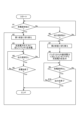
- 1 is a flowchart showing the processing of the power supply device.
- the power supply device is configured to output DC power for charging a battery mounted on a vehicle, and also to output AC power based on the power stored in the battery.
- the power supply device 1 of this embodiment will be described below.
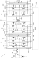
- FIG. 1 is a circuit diagram of the power supply device 1.
- the power supply device 1 is configured with an inverter 10, a converter 20, a reactor coil 30, a switching unit 40, and a control unit 50.
- Each functional unit is constructed with hardware or software, or both, with a CPU as the core component, in order to perform the processes related to the output of the DC power and AC power described above.
- the inverter 10 When AC power is input, the inverter 10 converts it to DC power and outputs it, and when DC power is input, it converts it to AC power and outputs it. That is, the inverter 10 of this embodiment may receive either AC power or DC power.
- the AC power input to the inverter 10 is power composed of an AC voltage whose voltage value oscillates at a predetermined cycle. Specifically, the AC voltage oscillates at a commercial frequency (e.g., 50 Hz or 60 Hz) and corresponds to an AC voltage of 200 V (effective value) taken from a commercial power source supplied in a single-phase three-wire system.
- the DC power output from the inverter 10 is power composed of a DC voltage that has a constant voltage value (excluding ripple voltage) relative to a reference voltage.
- the inverter 10 converts it to DC power composed of a DC voltage and outputs it.
- the DC power input to the inverter 10 refers to power composed of a DC voltage whose voltage value is a constant voltage value (excluding ripple voltage) relative to a reference voltage. Specifically, it corresponds to power based on the DC voltage output from the battery 3 mounted on the vehicle.
- the AC power output from the inverter 10 refers to power composed of an AC voltage whose voltage value oscillates at a predetermined period. Specifically, it corresponds to AC power composed of an AC voltage of 100 V (effective value), for example, which oscillates at the same frequency as the commercial frequency (for example, 50 Hz or 60 Hz).
- the inverter 10 converts it to AC power composed of an AC voltage of 100 V, for example, and outputs it.
- the inverter 10 is provided with a pair of terminals 10A, 10B.
- the inverter 10 outputs DC power converted from AC power to a converter 20 (described below) via the pair of terminals 10A, 10B.
- DC power from the battery 3 is input to the pair of terminals 10A, 10B via the converter 20.
- the inverter 10 has a first leg 11 and a second leg 12.
- the first leg 11 and the second leg 12 are arranged in parallel with each other with respect to the terminals 10A and 10B.
- one end 11A of the first leg 11 and one end 12A of the second leg 12 are connected to the terminal 10A
- the other end 11B of the first leg 11 and the other end 12B of the second leg 12 are connected to the terminal 10B.
- the first leg 11 has a high-side switching element 11H and a low-side switching element 11L connected in series.
- n-type MOS-FETs metal-oxide-semiconductor field-effect transistors
- the drain terminal of the switching element 11H is connected to the end 11A
- the source terminal is connected to the drain terminal of the switching element 11L.
- the source terminal of the switching element 11L is connected to the end 11B.
- the gate terminals of the switching elements 11H and 11L are connected to the control unit 50.
- diodes 11HD and 11LD are provided between the source terminals and drain terminals of the switching elements 11H and 11L, with the anode terminals connected to the source terminals and the cathode terminals connected to the drain terminals.
- the second leg 12 also has a high-side switching element 12H and a low-side switching element 12L connected in series.
- n-type MOS-FETs are used for the switching elements 12H and 12L.
- the drain terminal of the switching element 12H is connected to the end 12A, and the source terminal is connected to the drain terminal of the switching element 12L.
- the source terminal of the switching element 12L is connected to the end 12B.
- the gate terminals of the switching elements 12H and 12L are connected to the control unit 50.
- Diodes 12HD and 12LD are provided between the source terminals and drain terminals of the switching elements 12H and 12L, with the anode terminals connected to the source terminals and the cathode terminals connected to the drain terminals.
- a capacitor 15 is provided across terminals 10A and 10B of inverter 10. Capacitor 15 smoothes the DC voltage converted by inverter 10.
- the reactor coil 30 has one terminal 30B connected to a first node 11N between two switching elements (switching element 11H and switching element 11L) in the first leg 11.
- the first node 11N between the two switching elements in the first leg 11 is a line (e.g., a wiring pattern on a board or a cable such as a harness) connecting the source terminal of switching element 11H and the drain terminal of switching element 11L.
- a line e.g., a wiring pattern on a board or a cable such as a harness
- the reactor coil 30 has two terminals 30A, 30B, and the terminal 30B is connected to the first node 11N.
- the second node 12N between the two switching elements in the second leg 12 is a line (e.g., a wiring pattern on a board or a cable such as a harness) connecting the source terminal of the switching element 12H and the drain terminal of the switching element 12L. Of course, it may be the source terminal of the switching element 12H or the drain terminal of the switching element 12L.
- the terminal 30A of the reactor coil 30 is connected to one terminal of the supply unit 2 to which AC power is supplied, and the other terminal of the supply unit 2 is connected to the second node 12N. Therefore, the AC power supplied to the inverter 10 is generated by the switching element 11H and switching element 11L of the first leg 11 and the switching element 12H and switching element 12L of the second leg 12.
- the converter 20 can convert the DC power from the inverter 10 into DC power composed of a DC voltage of a first voltage value capable of charging the battery 3, and can convert the DC power from the battery 3 into DC power composed of a DC voltage of a second voltage value different from the first voltage value.
- the DC power from the inverter 10 is the DC power output from terminals 10A and 10B of the inverter 10.
- the battery 3 is a battery mounted on a vehicle that is charged by the power supply device 1, and is charged based on the DC power output from the converter 20.
- the battery 3 is charged with a DC voltage of an arbitrary voltage value, but the voltage value of the DC voltage that constitutes the DC power output from the inverter 10 is an arbitrary voltage value.
- the converter 20 converts the voltage value of the DC voltage output from the inverter 10 into an arbitrary DC voltage required for charging the battery 3.
- the DC power from the battery 3 is the DC power input from the battery 3 via the terminals 10A and 10B of the inverter 10.
- the voltage value of the DC voltage constituting the DC power from the battery 3 is approximately the same as the first voltage value (several hundred volts).
- the second voltage value is a DC voltage value equal to or greater than the voltage value of the AC voltage constituting the AC power output from the inverter 10. Therefore, the converter 20 converts the voltage value of the DC voltage input from the battery 3 to a DC voltage value equal to or greater than the voltage value of the AC voltage constituting the AC power output from the inverter 10, and outputs the DC voltage.
- the converter 20 of this embodiment has a first conversion unit 21, a second conversion unit 22, and a transformer 24.
- the transformer 24 is an isolated transformer having a primary winding 24A and a secondary winding 24B.
- the first conversion unit 21 oscillates the DC power from the inverter 10 at a predetermined period and inputs it to the primary winding 24A.
- the first conversion unit 21 has a third leg 211 and a fourth leg 212, which are arranged in parallel with each other with respect to the terminals 10A and 10B. Therefore, one end 211A of the third leg 211 and one end 212A of the fourth leg 212 are connected to the terminal 10A, and the other end 211B of the third leg 211 and the other end 212B of the fourth leg 212 are connected to the terminal 10B.
- the third leg 211 has a high-side switching element 211H and a low-side switching element 211L connected in series.
- the switching elements 211H and 211L are n-type MOS-FETs.
- the drain terminal of the switching element 211H is connected to the end 211A, and the source terminal is connected to the drain terminal of the switching element 211L.
- the source terminal of the switching element 211L is connected to the end 211B.
- the gate terminals of the switching elements 211H and 211L are connected to the control unit 50.
- diodes 211HD and 211LD are provided, with the anode terminals connected to the source terminals and the cathode terminals connected to the drain terminals.
- the fourth leg 212 has a high-side switching element 212H and a low-side switching element 212L connected in series.
- the switching elements 212H and 212L are n-type MOS-FETs.
- the drain terminal of the switching element 212H is connected to the end 212A, and the source terminal is connected to the drain terminal of the switching element 212L.
- the source terminal of the switching element 212L is connected to the end 212B.
- the gate terminals of the switching elements 212H and 212L are connected to the control unit 50.
- diodes 212HD and 212LD are provided, with the anode terminals connected to the source terminals and the cathode terminals connected to the drain terminals.
- the primary winding 24A is provided across a third node 211N between the two switching elements (switching element 211H and switching element 211L) in the third leg 211 and a fourth node 212N between the two switching elements (switching element 212H and switching element 212L) in the fourth leg 212.
- the winding start end of the primary winding 24A is connected to the third node 211N
- the winding end end of the primary winding 24A is connected to the fourth node 212N.
- the second conversion unit 22 rectifies the voltage (alternating voltage) generated in the secondary winding 24B.
- the second conversion unit 22 has a fifth leg 221 and a sixth leg 222, and the fifth leg 221 and the sixth leg 222 are provided in parallel with each other with respect to the terminals 20A and 20B of the converter 20.
- one end 221A of the fifth leg 221 and one end 222A of the sixth leg 222 are connected to the terminal 20A, and the other end 221B of the fifth leg 221 and the other end 222B of the sixth leg 222 are connected to the terminal 20B.
- the fifth leg 221 has a high-side switching element 221H and a low-side switching element 221L connected in series.
- the switching elements 221H and 221L are n-type MOS-FETs.
- the drain terminal of the switching element 221H is connected to the end 221A, and the source terminal is connected to the drain terminal of the switching element 221L.
- the source terminal of the switching element 221L is connected to the end 221B.
- the gate terminals of the switching elements 221H and 221L are connected to the control unit 50.
- diodes 221HD and 221LD are provided, with the anode terminals connected to the source terminals and the cathode terminals connected to the drain terminals.
- the sixth leg 222 has a high-side switching element 222H and a low-side switching element 222L connected in series.
- the switching elements 222H and 222L are n-type MOS-FETs.
- the drain terminal of the switching element 222H is connected to the end 222A, and the source terminal is connected to the drain terminal of the switching element 222L.
- the source terminal of the switching element 222L is connected to the end 222B.
- the gate terminals of the switching elements 222H and 222L are connected to the control unit 50.
- diodes 222HD and 222LD are provided, with the anode terminals connected to the source terminals and the cathode terminals connected to the drain terminals.
- the secondary winding 24B described above is provided across a fifth node 221N between the two switching elements (switching element 221H and switching element 221L) in the fifth leg 221 and a sixth node 222N between the two switching elements (switching element 222H and switching element 222L) in the sixth leg 222.
- the winding start end of the secondary winding 24B is connected to the fifth node 221N
- the winding end end of the secondary winding 24B is connected to the sixth node 222N.
- a capacitor 25 is provided across terminals 20A and 20B of converter 20. Capacitor 25 smoothes the DC voltage converted by second conversion unit 22.
- the switching unit 40 switches the conversion operation of the inverter 10 and the converter 20.
- the conversion operation of the inverter 10 and the converter 20 corresponds to the operation of converting AC power to DC power and the operation of converting DC power to AC power, which are performed by the inverter 10 and the converter 20, respectively.
- the converter 20 is switched from one of a first state and a second state to the other by the switching unit 40.
- the first state is a state in which the converter 20 converts the DC power from the inverter 10 into DC power composed of a DC voltage of a first voltage value.
- the second state is a state in which the converter 20 converts the DC power from the battery 3 into DC power composed of a DC voltage of a second voltage value.
- the switching unit 40 can be configured with a mechanism that can be manually operated by the user, and can be configured using an alternate switch, for example. As shown in FIG. 1, when the switching unit 40 is operated to connect terminals 0 and 1, AC power supplied from the supply unit 2 is input to the inverter 10 via the reactor coil 30. Also, as shown in FIG. 2, when the switching unit 40 is operated to connect terminals 0 and 3, AC power generated based on DC power from the battery 3 can be taken out from the outlet 4 via the reactor coil 30.
- the switching unit 40 switches the converter 20 to the first state, and when there is an output request to output AC power from the inverter 10 (when the control unit 50 makes an output request to output AC power from the inverter 10), the switching unit 40 switches the converter 20 to the second state. That is, when an operation is made to connect terminals 0 and 1 as a request to charge the battery 3, the switching unit 40 switches the converter 20 to the first state, and when an operation is made to connect terminals 0 and 3 as an output request to output AC power from the inverter 10, the switching unit 40 switches the converter 20 to the second state.
- the control unit 50 controls the driving of the inverter 10. Specifically, the control unit 50 alternately drives the switching elements 11H and 11L of the first leg 11 and the switching elements 12H and 12L of the second leg 12. This drives the switching elements of the first leg 11 and the second leg 12 of the inverter 10, converting AC power into DC power.
- the control unit 50 also controls the driving of the converter 20. Specifically, the control unit 50 alternately drives the switching element 211H of the third leg 211 and the switching element 212L of the fourth leg 212, and the switching element 211L of the third leg 211 and the switching element 212H of the fourth leg 212. This makes it possible for the DC power from the inverter 10 to be amplified and input to the primary winding 24A, and for the secondary winding 24B to generate AC power according to the turns ratio between the primary winding 24A and the secondary winding 24B.
- control unit 50 alternately drives the switching element 221H of the fifth leg 221 and the switching element 222L of the sixth leg 222, and the switching element 221L of the fifth leg 221 and the switching element 222H of the sixth leg 222. This converts the AC voltage generated in the secondary winding 24B into a DC voltage. The battery 3 is charged by this DC voltage.
- the control unit 50 alternately drives the switching element 221H of the fifth leg 221 and the switching element 222L of the sixth leg 222, and the switching element 221L of the fifth leg 221 and the switching element 222H of the sixth leg 222.
- This allows the DC power from the battery 3 to be amplified and input to the secondary winding 24B, and makes it possible to generate AC power in the primary winding 24A according to the turns ratio between the primary winding 24A and the secondary winding 24B.
- the control unit 50 alternately drives the switching element 211H of the third leg 211 and the switching element 212L of the fourth leg 212, and the switching element 211L of the third leg 211 and the switching element 212H of the fourth leg 212.
- This converts the AC voltage generated in the primary winding 24A into a DC voltage.
- This DC voltage is a voltage obtained by transforming the output voltage of the battery 3 according to the turns ratio between the primary winding 24A and the secondary winding 24B.
- control unit 50 alternately drives the switching elements 11H and 11L of the first leg 11 and the switching elements 12H and 12L of the second leg 12.
- step #1: Yes When a charging request is made to the switching unit 40 (step #1: Yes), the switching unit 40 switches the state of the converter 20 to the first state (step #2). In this case, the battery 3 is charged in response to the input of AC power to the supply unit 2 (step #3).
- Step #4: Yes If, during charging of the battery 3, there is no request to output AC power by operating the switching unit 40 (Step #4: Yes) and charging of the battery 3 is not to be terminated (Step #5: No), the power supply device 1 continues charging the battery 3. On the other hand, if there is no request to output AC power by operating the switching unit 40 (Step #4: Yes) and charging of the battery 3 is to be terminated (Step #5: Yes), the power supply device 1 terminates charging of the battery 3.
- step #1 if there is no charging request to the switching unit 40 (step #1: No) and there is an output request (step #6: Yes), the switching unit 40 switches the state of the converter 20 to the second state (step #7). In this case, AC power is output from the outlet 4 in response to the DC power from the battery 3 (step #8).
- Step #9: Yes When AC power is being output from the outlet 4, if there is no request to charge the battery 3 by operation of the switching unit 40 (Step #9: Yes) and the output of AC power from the outlet 4 is not to be terminated (Step #10: No), the power supply device 1 continues to supply AC power from the outlet 4. On the other hand, if there is no request to charge the battery 3 by operation of the switching unit 40 (Step #9: Yes) and the output of AC power is to be terminated (Step #10: Yes), the power supply device 1 terminates the output of AC power.
- step #4 if there is a request to output AC power from the outlet 4 while the battery 3 is being charged (step #4: No), processing continues from step #7. Also, in step #9, if there is a request to charge the battery 3 while AC power is being output from the outlet 4 (step #9: No), processing continues from step #2.
- the switching elements of the inverter 10 and the converter 20 are described as n-type MOS-FETs.
- the switching elements may be p-type MOS-FETs or switching elements other than FETs (e.g., IGBTs or bipolar transistors).
- the inverter 10 and converter 20 are described as converting AC power to DC power using switching elements, but the inverter 10 may also be configured to convert AC power to DC power using diodes.
- the switching unit 40 is described as being configured using an alternate switch, but the switching unit 40 may be configured to switch, for example, by operating an icon displayed on a display device, or may be configured to detect at least one of the supply of AC power to the supply unit 2 and the connection of an AC load to the outlet 4 and switch the conversion operation.
- the switching unit 40 can be configured using an alternate switch, but it may also be configured using a relay.
- the switching unit 40 may be a software switch that switches the operation (operation mode) of the inverter 10 and the converter 20 by software.
- the power supply device 1 is characterized in that it includes an inverter 10 that converts input AC power into DC power and outputs it, and that converts input DC power into AC power and outputs it, a converter 20 that can convert the DC power from the inverter 10 into DC power composed of a DC voltage of a first voltage value capable of charging the battery 3, and that can convert the DC power from the battery 3 into DC power composed of a DC voltage of a second voltage value different from the first voltage value, and a switching unit 40 that switches the conversion operation of the inverter 10 and the converter 20.
- This characteristic configuration allows the power supply device 1 to charge the battery 3 via the inverter 10, and when the battery 3 is not being charged, it is possible to output AC power based on the DC power from the battery 3. Therefore, the inverter 10 and the converter 20 can be used together when charging the battery 3 and when outputting AC power based on the DC power from the battery 3, making it possible to reduce the size and achieve lower costs compared to when the inverter 10 and the converter 20 are not used together.
- the converter 20 converts the voltage value of the DC voltage constituting the input DC power to a voltage value of a DC voltage suitable for charging the battery 3, and when outputting AC power based on the DC power from the battery 3, it is necessary to convert the DC voltage value to a DC voltage value equal to or higher than the voltage value of the AC voltage constituting the AC power output from the inverter 10. Therefore, with the above configuration, it becomes possible to easily switch the operation of the converter 20 between when charging the battery 3 and when outputting AC power based on the DC power from the battery 3.
- This configuration makes it possible for the power supply device 1 to charge the battery 3 based on the DC power generated by the converter 20.
- control unit 50 that controls the driving of the inverter 10 and the converter 20, and when the control unit 50 issues an output request to output AC power from the inverter 10, the switching unit 40 switches the converter 20 to the second state.
- This configuration enables the power supply device 1 to output AC power from the inverter 10 based on the DC power generated by the converter 20.
- the switching unit 40 is a mechanism that can be manually operated by a user.
- the power supply device 1 described in (1) to (4) further includes a supply unit 2 that supplies AC power input to the inverter 10, and an outlet 4 that outputs AC power using DC power from the battery 3, and the switching unit 40 can be configured to detect at least one of the supply of AC power to the supply unit 2 and the connection of an AC load to the outlet 4 and switch the conversion operation.
- the supply of AC power to the supply unit 2 and the connection of an AC load to the outlet 4 may be detected by a detection mechanism (not shown) that physically detects, for example, the connection of the supply unit 2 to a supplied unit (not shown) or the connection of the AC load connection unit (not shown) to the outlet 4, or may be detected by a sensor unit (not shown) that electrically detects.
- the present invention can be used in a power supply device that charges and discharges a battery installed in a vehicle.
Landscapes
- Engineering & Computer Science (AREA)
- Power Engineering (AREA)
- Transportation (AREA)
- Mechanical Engineering (AREA)
- Life Sciences & Earth Sciences (AREA)
- Sustainable Development (AREA)
- Sustainable Energy (AREA)
- Charge And Discharge Circuits For Batteries Or The Like (AREA)
Abstract
Description
上記実施形態では、インバータ10及びコンバータ20が有するスイッチング素子が、n型MOS-FETであるとして説明したが、スイッチング素子はp型MOS-FETでもよいし、FETとは異なるスイッチング素子(例えばIGBTやバイポーラトランジスタ)であってもよい。
以下、上記において説明した電源装置1の概要について説明する。
Claims (6)
- 交流電力が入力された場合は直流電力に変換して出力し、直流電力が入力された場合は交流電力に変換して出力するインバータと、
前記インバータからの前記直流電力を、バッテリを充電可能な第1電圧値の直流電圧で構成される直流電力に変換可能であり、前記バッテリからの直流電力を、前記第1電圧値とは異なる第2電圧値の直流電圧で構成される直流電力に変換可能なコンバータと、
前記インバータ及び前記コンバータの変換動作を切り替える切替部と、
を備える電源装置。 - 前記コンバータが前記インバータからの前記直流電力を前記第1電圧値の直流電圧で構成される直流電力に変換する状態を第1状態とし、前記バッテリからの前記直流電力を前記第2電圧値の直流電圧で構成される直流電力に変換する状態を第2状態とした場合に、 前記切替部は、前記第1状態及び前記第2状態の一方から他方に切り替える請求項1に記載の電源装置。
- 前記バッテリを充電する充電要求があった場合に、前記切替部は前記コンバータを前記第1状態に切り替える請求項2に記載の電源装置。
- 前記インバータ及び前記コンバータの駆動を制御する制御部を更に備え、
前記制御部が前記交流電力を前記インバータから出力させる出力要求を行った場合に、前記切替部は前記コンバータを前記第2状態に切り替える請求項2に記載の電源装置。 - 前記切替部は、ユーザが手動で操作することが可能な機構である請求項1から4のいずれか一項に記載の電源装置。
- 前記インバータに入力される前記交流電力を供給する供給部と、
前記バッテリからの前記直流電力を利用して交流電力を出力するコンセントと、を更に備え、
前記切替部は、前記供給部への前記交流電力の供給及び前記コンセントへの交流負荷の接続の少なくともいずれか一方を検出して前記変換動作を切り替える請求項1から4のいずれか一項に記載の電源装置。
Priority Applications (3)
| Application Number | Priority Date | Filing Date | Title |
|---|---|---|---|
| JP2024558732A JPWO2024106151A1 (ja) | 2022-11-16 | 2023-10-25 | |
| EP23891306.5A EP4576554A4 (en) | 2022-11-16 | 2023-10-25 | POWER SUPPLY DEVICE |
| CN202380072483.3A CN120130009A (zh) | 2022-11-16 | 2023-10-25 | 电源装置 |
Applications Claiming Priority (2)
| Application Number | Priority Date | Filing Date | Title |
|---|---|---|---|
| JP2022-183682 | 2022-11-16 | ||
| JP2022183682 | 2022-11-16 |
Publications (1)
| Publication Number | Publication Date |
|---|---|
| WO2024106151A1 true WO2024106151A1 (ja) | 2024-05-23 |
Family
ID=91084292
Family Applications (1)
| Application Number | Title | Priority Date | Filing Date |
|---|---|---|---|
| PCT/JP2023/038466 Ceased WO2024106151A1 (ja) | 2022-11-16 | 2023-10-25 | 電源装置 |
Country Status (4)
| Country | Link |
|---|---|
| EP (1) | EP4576554A4 (ja) |
| JP (1) | JPWO2024106151A1 (ja) |
| CN (1) | CN120130009A (ja) |
| WO (1) | WO2024106151A1 (ja) |
Citations (4)
| Publication number | Priority date | Publication date | Assignee | Title |
|---|---|---|---|---|
| JPH11178234A (ja) * | 1997-12-10 | 1999-07-02 | Nissan Motor Co Ltd | 電気自動車を用いた家庭用電力供給システム |
| JP2015015895A (ja) * | 2011-06-30 | 2015-01-22 | パナソニックIpマネジメント株式会社 | 電源装置 |
| JP2017158322A (ja) | 2016-03-02 | 2017-09-07 | オムロンオートモーティブエレクトロニクス株式会社 | 充電器 |
| JP2022134859A (ja) * | 2021-03-04 | 2022-09-15 | オムロン株式会社 | 電力供給システム及び双方向電力変換装置 |
Family Cites Families (3)
| Publication number | Priority date | Publication date | Assignee | Title |
|---|---|---|---|---|
| US11376977B2 (en) * | 2018-12-30 | 2022-07-05 | Texas Instruments Incorporated | Powertrain architecture for a vehicle utilizing an on-board charger |
| CN110707792B (zh) * | 2019-10-24 | 2022-05-31 | 华为数字能源技术有限公司 | 一种车载充放电系统及控制方法 |
| JP7528784B2 (ja) * | 2020-12-28 | 2024-08-06 | トヨタ自動車株式会社 | 電力伝送システム |
-
2023
- 2023-10-25 CN CN202380072483.3A patent/CN120130009A/zh active Pending
- 2023-10-25 JP JP2024558732A patent/JPWO2024106151A1/ja active Pending
- 2023-10-25 WO PCT/JP2023/038466 patent/WO2024106151A1/ja not_active Ceased
- 2023-10-25 EP EP23891306.5A patent/EP4576554A4/en active Pending
Patent Citations (4)
| Publication number | Priority date | Publication date | Assignee | Title |
|---|---|---|---|---|
| JPH11178234A (ja) * | 1997-12-10 | 1999-07-02 | Nissan Motor Co Ltd | 電気自動車を用いた家庭用電力供給システム |
| JP2015015895A (ja) * | 2011-06-30 | 2015-01-22 | パナソニックIpマネジメント株式会社 | 電源装置 |
| JP2017158322A (ja) | 2016-03-02 | 2017-09-07 | オムロンオートモーティブエレクトロニクス株式会社 | 充電器 |
| JP2022134859A (ja) * | 2021-03-04 | 2022-09-15 | オムロン株式会社 | 電力供給システム及び双方向電力変換装置 |
Non-Patent Citations (1)
| Title |
|---|
| See also references of EP4576554A4 |
Also Published As
| Publication number | Publication date |
|---|---|
| JPWO2024106151A1 (ja) | 2024-05-23 |
| CN120130009A (zh) | 2025-06-10 |
| EP4576554A4 (en) | 2025-12-10 |
| EP4576554A1 (en) | 2025-06-25 |
Similar Documents
| Publication | Publication Date | Title |
|---|---|---|
| US10897190B2 (en) | Power supply device, power control apparatus, and relay determination method for power supply device | |
| US10855193B2 (en) | Vehicle power supply device | |
| US9209698B2 (en) | Electric power conversion device | |
| CN113799629A (zh) | 用于对车辆的电池充电的装置及方法 | |
| US10778106B2 (en) | Power conversion system | |
| WO2011024635A1 (ja) | 電力変換装置 | |
| JP2023144659A (ja) | 電力供給システム | |
| CN110893823A (zh) | 车辆电源装置 | |
| EP3823131A1 (en) | Controller for charger device, charger device and method | |
| JP2022069834A (ja) | 電源制御装置 | |
| US11689112B2 (en) | DC-DC converter and vehicle | |
| JP2014171313A (ja) | Dc/dcコンバータ | |
| WO2024106382A1 (ja) | 電源装置 | |
| US20250091453A1 (en) | Power conversion device | |
| WO2024106151A1 (ja) | 電源装置 | |
| KR102781627B1 (ko) | 전력 변환 장치 | |
| WO2024202684A1 (ja) | 電源装置 | |
| JP2022138710A (ja) | Dc-dcコンバータおよび車両 | |
| CN119421809A (zh) | 电力转换装置 | |
| WO2022190988A1 (ja) | 電力変換装置 | |
| US12583329B2 (en) | Power conversion device | |
| JP7758000B2 (ja) | 充電装置 | |
| CA2996871C (en) | Power converting device and method of controlling power converting device | |
| JP2026022900A (ja) | 電源装置 | |
| JP2026007384A (ja) | 電源装置 |
Legal Events
| Date | Code | Title | Description |
|---|---|---|---|
| 121 | Ep: the epo has been informed by wipo that ep was designated in this application |
Ref document number: 23891306 Country of ref document: EP Kind code of ref document: A1 |
|
| WWE | Wipo information: entry into national phase |
Ref document number: 2024558732 Country of ref document: JP |
|
| WWE | Wipo information: entry into national phase |
Ref document number: 2023891306 Country of ref document: EP |
|
| ENP | Entry into the national phase |
Ref document number: 2023891306 Country of ref document: EP Effective date: 20250320 |
|
| WWE | Wipo information: entry into national phase |
Ref document number: 202380072483.3 Country of ref document: CN |
|
| WWP | Wipo information: published in national office |
Ref document number: 202380072483.3 Country of ref document: CN |
|
| NENP | Non-entry into the national phase |
Ref country code: DE |
|
| WWP | Wipo information: published in national office |
Ref document number: 2023891306 Country of ref document: EP |