WO2024106330A1 - 冷却システム - Google Patents
冷却システム Download PDFInfo
- Publication number
- WO2024106330A1 WO2024106330A1 PCT/JP2023/040548 JP2023040548W WO2024106330A1 WO 2024106330 A1 WO2024106330 A1 WO 2024106330A1 JP 2023040548 W JP2023040548 W JP 2023040548W WO 2024106330 A1 WO2024106330 A1 WO 2024106330A1
- Authority
- WO
- WIPO (PCT)
- Prior art keywords
- cooling
- heat exchanger
- unit
- flow path
- electronic circuit
- Prior art date
- Legal status (The legal status is an assumption and is not a legal conclusion. Google has not performed a legal analysis and makes no representation as to the accuracy of the status listed.)
- Ceased
Links
Images


Classifications
-
- H—ELECTRICITY
- H02—GENERATION; CONVERSION OR DISTRIBUTION OF ELECTRIC POWER
- H02K—DYNAMO-ELECTRIC MACHINES
- H02K11/00—Structural association of dynamo-electric machines with electric components or with devices for shielding, monitoring or protection
- H02K11/30—Structural association with control circuits or drive circuits
- H02K11/33—Drive circuits, e.g. power electronics
-
- B—PERFORMING OPERATIONS; TRANSPORTING
- B60—VEHICLES IN GENERAL
- B60H—ARRANGEMENTS OF HEATING, COOLING, VENTILATING OR OTHER AIR-TREATING DEVICES SPECIALLY ADAPTED FOR PASSENGER OR GOODS SPACES OF VEHICLES
- B60H1/00—Heating, cooling or ventilating devices
- B60H1/00271—HVAC devices specially adapted for particular vehicle parts or components and being connected to the vehicle HVAC unit
- B60H1/00278—HVAC devices specially adapted for particular vehicle parts or components and being connected to the vehicle HVAC unit for the battery
-
- B—PERFORMING OPERATIONS; TRANSPORTING
- B60—VEHICLES IN GENERAL
- B60H—ARRANGEMENTS OF HEATING, COOLING, VENTILATING OR OTHER AIR-TREATING DEVICES SPECIALLY ADAPTED FOR PASSENGER OR GOODS SPACES OF VEHICLES
- B60H1/00—Heating, cooling or ventilating devices
- B60H1/00642—Control systems or circuits; Control members or indication devices for heating, cooling or ventilating devices
- B60H1/00814—Control systems or circuits characterised by their output, for controlling particular components of the heating, cooling or ventilating installation
- B60H1/00878—Control systems or circuits characterised by their output, for controlling particular components of the heating, cooling or ventilating installation the components being temperature regulating devices
- B60H1/00899—Controlling the flow of liquid in a heat pump system
- B60H1/00921—Controlling the flow of liquid in a heat pump system where the flow direction of the refrigerant does not change and there is an extra subcondenser, e.g. in an air duct
-
- B—PERFORMING OPERATIONS; TRANSPORTING
- B60—VEHICLES IN GENERAL
- B60K—ARRANGEMENT OR MOUNTING OF PROPULSION UNITS OR OF TRANSMISSIONS IN VEHICLES; ARRANGEMENT OR MOUNTING OF PLURAL DIVERSE PRIME-MOVERS IN VEHICLES; AUXILIARY DRIVES FOR VEHICLES; INSTRUMENTATION OR DASHBOARDS FOR VEHICLES; ARRANGEMENTS IN CONNECTION WITH COOLING, AIR INTAKE, GAS EXHAUST OR FUEL SUPPLY OF PROPULSION UNITS IN VEHICLES
- B60K1/00—Arrangement or mounting of electrical propulsion units
-
- B—PERFORMING OPERATIONS; TRANSPORTING
- B60—VEHICLES IN GENERAL
- B60K—ARRANGEMENT OR MOUNTING OF PROPULSION UNITS OR OF TRANSMISSIONS IN VEHICLES; ARRANGEMENT OR MOUNTING OF PLURAL DIVERSE PRIME-MOVERS IN VEHICLES; AUXILIARY DRIVES FOR VEHICLES; INSTRUMENTATION OR DASHBOARDS FOR VEHICLES; ARRANGEMENTS IN CONNECTION WITH COOLING, AIR INTAKE, GAS EXHAUST OR FUEL SUPPLY OF PROPULSION UNITS IN VEHICLES
- B60K11/00—Arrangement in connection with cooling of propulsion units
- B60K11/02—Arrangement in connection with cooling of propulsion units with liquid cooling
- B60K11/04—Arrangement or mounting of radiators, radiator shutters, or radiator blinds
-
- B—PERFORMING OPERATIONS; TRANSPORTING
- B60—VEHICLES IN GENERAL
- B60L—PROPULSION OF ELECTRICALLY-PROPELLED VEHICLES; SUPPLYING ELECTRIC POWER FOR AUXILIARY EQUIPMENT OF ELECTRICALLY-PROPELLED VEHICLES; ELECTRODYNAMIC BRAKE SYSTEMS FOR VEHICLES IN GENERAL; MAGNETIC SUSPENSION OR LEVITATION FOR VEHICLES; MONITORING OPERATING VARIABLES OF ELECTRICALLY-PROPELLED VEHICLES; ELECTRIC SAFETY DEVICES FOR ELECTRICALLY-PROPELLED VEHICLES
- B60L1/00—Supplying electric power to auxiliary equipment of vehicles
- B60L1/02—Supplying electric power to auxiliary equipment of vehicles to electric heating circuits
-
- F—MECHANICAL ENGINEERING; LIGHTING; HEATING; WEAPONS; BLASTING
- F01—MACHINES OR ENGINES IN GENERAL; ENGINE PLANTS IN GENERAL; STEAM ENGINES
- F01P—COOLING OF MACHINES OR ENGINES IN GENERAL; COOLING OF INTERNAL-COMBUSTION ENGINES
- F01P11/00—Component parts, details, or accessories not provided for in, or of interest apart from, groups F01P1/00 - F01P9/00
- F01P11/04—Arrangements of liquid pipes or hoses
-
- F—MECHANICAL ENGINEERING; LIGHTING; HEATING; WEAPONS; BLASTING
- F01—MACHINES OR ENGINES IN GENERAL; ENGINE PLANTS IN GENERAL; STEAM ENGINES
- F01P—COOLING OF MACHINES OR ENGINES IN GENERAL; COOLING OF INTERNAL-COMBUSTION ENGINES
- F01P11/00—Component parts, details, or accessories not provided for in, or of interest apart from, groups F01P1/00 - F01P9/00
- F01P11/08—Arrangements of lubricant coolers
-
- F—MECHANICAL ENGINEERING; LIGHTING; HEATING; WEAPONS; BLASTING
- F01—MACHINES OR ENGINES IN GENERAL; ENGINE PLANTS IN GENERAL; STEAM ENGINES
- F01P—COOLING OF MACHINES OR ENGINES IN GENERAL; COOLING OF INTERNAL-COMBUSTION ENGINES
- F01P3/00—Liquid cooling
-
- F—MECHANICAL ENGINEERING; LIGHTING; HEATING; WEAPONS; BLASTING
- F01—MACHINES OR ENGINES IN GENERAL; ENGINE PLANTS IN GENERAL; STEAM ENGINES
- F01P—COOLING OF MACHINES OR ENGINES IN GENERAL; COOLING OF INTERNAL-COMBUSTION ENGINES
- F01P3/00—Liquid cooling
- F01P3/20—Cooling circuits not specific to a single part of engine or machine
-
- F—MECHANICAL ENGINEERING; LIGHTING; HEATING; WEAPONS; BLASTING
- F01—MACHINES OR ENGINES IN GENERAL; ENGINE PLANTS IN GENERAL; STEAM ENGINES
- F01P—COOLING OF MACHINES OR ENGINES IN GENERAL; COOLING OF INTERNAL-COMBUSTION ENGINES
- F01P3/00—Liquid cooling
- F01P3/22—Liquid cooling characterised by evaporation and condensation of coolant in closed cycles; characterised by the coolant reaching higher temperatures than normal atmospheric boiling-point
-
- F—MECHANICAL ENGINEERING; LIGHTING; HEATING; WEAPONS; BLASTING
- F01—MACHINES OR ENGINES IN GENERAL; ENGINE PLANTS IN GENERAL; STEAM ENGINES
- F01P—COOLING OF MACHINES OR ENGINES IN GENERAL; COOLING OF INTERNAL-COMBUSTION ENGINES
- F01P7/00—Controlling of coolant flow
- F01P7/14—Controlling of coolant flow the coolant being liquid
-
- F—MECHANICAL ENGINEERING; LIGHTING; HEATING; WEAPONS; BLASTING
- F25—REFRIGERATION OR COOLING; COMBINED HEATING AND REFRIGERATION SYSTEMS; HEAT PUMP SYSTEMS; MANUFACTURE OR STORAGE OF ICE; LIQUEFACTION SOLIDIFICATION OF GASES
- F25B—REFRIGERATION MACHINES, PLANTS OR SYSTEMS; COMBINED HEATING AND REFRIGERATION SYSTEMS; HEAT PUMP SYSTEMS
- F25B5/00—Compression machines, plants or systems, with several evaporator circuits, e.g. for varying refrigerating capacity
- F25B5/02—Compression machines, plants or systems, with several evaporator circuits, e.g. for varying refrigerating capacity arranged in parallel
-
- F—MECHANICAL ENGINEERING; LIGHTING; HEATING; WEAPONS; BLASTING
- F25—REFRIGERATION OR COOLING; COMBINED HEATING AND REFRIGERATION SYSTEMS; HEAT PUMP SYSTEMS; MANUFACTURE OR STORAGE OF ICE; LIQUEFACTION SOLIDIFICATION OF GASES
- F25B—REFRIGERATION MACHINES, PLANTS OR SYSTEMS; COMBINED HEATING AND REFRIGERATION SYSTEMS; HEAT PUMP SYSTEMS
- F25B6/00—Compression machines, plants or systems, with several condenser circuits
- F25B6/04—Compression machines, plants or systems, with several condenser circuits arranged in series
-
- H—ELECTRICITY
- H02—GENERATION; CONVERSION OR DISTRIBUTION OF ELECTRIC POWER
- H02K—DYNAMO-ELECTRIC MACHINES
- H02K9/00—Arrangements for cooling or ventilating
- H02K9/19—Arrangements for cooling or ventilating for machines with closed casing and closed-circuit cooling using a liquid cooling medium, e.g. oil
-
- B—PERFORMING OPERATIONS; TRANSPORTING
- B60—VEHICLES IN GENERAL
- B60H—ARRANGEMENTS OF HEATING, COOLING, VENTILATING OR OTHER AIR-TREATING DEVICES SPECIALLY ADAPTED FOR PASSENGER OR GOODS SPACES OF VEHICLES
- B60H1/00—Heating, cooling or ventilating devices
- B60H1/00271—HVAC devices specially adapted for particular vehicle parts or components and being connected to the vehicle HVAC unit
- B60H2001/00307—Component temperature regulation using a liquid flow
-
- B—PERFORMING OPERATIONS; TRANSPORTING
- B60—VEHICLES IN GENERAL
- B60K—ARRANGEMENT OR MOUNTING OF PROPULSION UNITS OR OF TRANSMISSIONS IN VEHICLES; ARRANGEMENT OR MOUNTING OF PLURAL DIVERSE PRIME-MOVERS IN VEHICLES; AUXILIARY DRIVES FOR VEHICLES; INSTRUMENTATION OR DASHBOARDS FOR VEHICLES; ARRANGEMENTS IN CONNECTION WITH COOLING, AIR INTAKE, GAS EXHAUST OR FUEL SUPPLY OF PROPULSION UNITS IN VEHICLES
- B60K1/00—Arrangement or mounting of electrical propulsion units
- B60K1/04—Arrangement or mounting of electrical propulsion units of the electric storage means for propulsion
-
- B—PERFORMING OPERATIONS; TRANSPORTING
- B60—VEHICLES IN GENERAL
- B60K—ARRANGEMENT OR MOUNTING OF PROPULSION UNITS OR OF TRANSMISSIONS IN VEHICLES; ARRANGEMENT OR MOUNTING OF PLURAL DIVERSE PRIME-MOVERS IN VEHICLES; AUXILIARY DRIVES FOR VEHICLES; INSTRUMENTATION OR DASHBOARDS FOR VEHICLES; ARRANGEMENTS IN CONNECTION WITH COOLING, AIR INTAKE, GAS EXHAUST OR FUEL SUPPLY OF PROPULSION UNITS IN VEHICLES
- B60K1/00—Arrangement or mounting of electrical propulsion units
- B60K2001/003—Arrangement or mounting of electrical propulsion units with means for cooling the electrical propulsion units
- B60K2001/005—Arrangement or mounting of electrical propulsion units with means for cooling the electrical propulsion units the electric storage means
-
- B—PERFORMING OPERATIONS; TRANSPORTING
- B60—VEHICLES IN GENERAL
- B60K—ARRANGEMENT OR MOUNTING OF PROPULSION UNITS OR OF TRANSMISSIONS IN VEHICLES; ARRANGEMENT OR MOUNTING OF PLURAL DIVERSE PRIME-MOVERS IN VEHICLES; AUXILIARY DRIVES FOR VEHICLES; INSTRUMENTATION OR DASHBOARDS FOR VEHICLES; ARRANGEMENTS IN CONNECTION WITH COOLING, AIR INTAKE, GAS EXHAUST OR FUEL SUPPLY OF PROPULSION UNITS IN VEHICLES
- B60K1/00—Arrangement or mounting of electrical propulsion units
- B60K2001/003—Arrangement or mounting of electrical propulsion units with means for cooling the electrical propulsion units
- B60K2001/006—Arrangement or mounting of electrical propulsion units with means for cooling the electrical propulsion units the electric motors
-
- B—PERFORMING OPERATIONS; TRANSPORTING
- B60—VEHICLES IN GENERAL
- B60L—PROPULSION OF ELECTRICALLY-PROPELLED VEHICLES; SUPPLYING ELECTRIC POWER FOR AUXILIARY EQUIPMENT OF ELECTRICALLY-PROPELLED VEHICLES; ELECTRODYNAMIC BRAKE SYSTEMS FOR VEHICLES IN GENERAL; MAGNETIC SUSPENSION OR LEVITATION FOR VEHICLES; MONITORING OPERATING VARIABLES OF ELECTRICALLY-PROPELLED VEHICLES; ELECTRIC SAFETY DEVICES FOR ELECTRICALLY-PROPELLED VEHICLES
- B60L2220/00—Electrical machine types; Structures or applications thereof
- B60L2220/50—Structural details of electrical machines
-
- B—PERFORMING OPERATIONS; TRANSPORTING
- B60—VEHICLES IN GENERAL
- B60L—PROPULSION OF ELECTRICALLY-PROPELLED VEHICLES; SUPPLYING ELECTRIC POWER FOR AUXILIARY EQUIPMENT OF ELECTRICALLY-PROPELLED VEHICLES; ELECTRODYNAMIC BRAKE SYSTEMS FOR VEHICLES IN GENERAL; MAGNETIC SUSPENSION OR LEVITATION FOR VEHICLES; MONITORING OPERATING VARIABLES OF ELECTRICALLY-PROPELLED VEHICLES; ELECTRIC SAFETY DEVICES FOR ELECTRICALLY-PROPELLED VEHICLES
- B60L2240/00—Control parameters of input or output; Target parameters
- B60L2240/10—Vehicle control parameters
- B60L2240/36—Temperature of vehicle components or parts
-
- B—PERFORMING OPERATIONS; TRANSPORTING
- B60—VEHICLES IN GENERAL
- B60L—PROPULSION OF ELECTRICALLY-PROPELLED VEHICLES; SUPPLYING ELECTRIC POWER FOR AUXILIARY EQUIPMENT OF ELECTRICALLY-PROPELLED VEHICLES; ELECTRODYNAMIC BRAKE SYSTEMS FOR VEHICLES IN GENERAL; MAGNETIC SUSPENSION OR LEVITATION FOR VEHICLES; MONITORING OPERATING VARIABLES OF ELECTRICALLY-PROPELLED VEHICLES; ELECTRIC SAFETY DEVICES FOR ELECTRICALLY-PROPELLED VEHICLES
- B60L2240/00—Control parameters of input or output; Target parameters
- B60L2240/40—Drive Train control parameters
- B60L2240/42—Drive Train control parameters related to electric machines
- B60L2240/425—Temperature
-
- F—MECHANICAL ENGINEERING; LIGHTING; HEATING; WEAPONS; BLASTING
- F25—REFRIGERATION OR COOLING; COMBINED HEATING AND REFRIGERATION SYSTEMS; HEAT PUMP SYSTEMS; MANUFACTURE OR STORAGE OF ICE; LIQUEFACTION SOLIDIFICATION OF GASES
- F25B—REFRIGERATION MACHINES, PLANTS OR SYSTEMS; COMBINED HEATING AND REFRIGERATION SYSTEMS; HEAT PUMP SYSTEMS
- F25B2339/00—Details of evaporators; Details of condensers
- F25B2339/04—Details of condensers
- F25B2339/047—Water-cooled condensers
Definitions
- the present invention relates to a cooling system.
- an electric vehicle drive unit that includes at least an electric motor that transmits drive torque to the vehicle's running system (see, for example, Patent Document 1).
- This electric vehicle drive unit is made compact by integrating the electric motor and gear unit into a housing, and is connected to a cooling system that exchanges heat between the oil circulating in the electric vehicle drive unit and the coolant.
- the cooling system described in Patent Document 1 attaches an inverter unit to an electric vehicle drive unit, and exchanges heat between the cooling water circulating from the inverter unit to an oil cooler and the oil circulating in the electric vehicle drive unit.
- the oil cooler is attached to the lower part of the motor housing of the electric vehicle drive unit, and cooling piping is routed between the oil cooler and the inverter unit.
- the oil cooler is attached to the bottom of the housing and the cooling piping is exposed, so heat is dissipated through the cooling piping, reducing the heat recovery rate.
- the cooling system is characterized by the following features: an integrated unit that integrates an electric vehicle drive unit including at least an electric motor that transmits drive torque to the vehicle's running system, and an electronic circuit unit including at least an electronic circuit for driving the electric motor; a cooling flow path that circulates a coolant through the electronic circuit unit; and an oil flow path that circulates oil through the electric vehicle drive unit, the oil flow path having a heat exchanger that exchanges heat with the coolant circulating through the cooling flow path, the heat exchanger being disposed inside the integrated unit between the electric vehicle drive unit and the electronic circuit unit.
- an integrated unit that integrates the electric vehicle drive unit and the electronic circuit unit, making it possible to achieve a smaller size compared to a case in which the electric vehicle drive unit and the electronic circuit unit are arranged separately.
- the waste heat of the electric vehicle drive unit can be recovered by the coolant using a heat exchanger that exchanges heat between the coolant and oil.
- the heat exchanger is placed inside the integrated unit, between the electric vehicle drive unit and the electronic circuit unit. This makes it possible to exchange heat between the oil and the coolant inside the integrated unit, improving the heat recovery rate. It also makes it possible to shorten the length of the piping in the cooling flow path that is exposed to the outside from the heat exchanger.
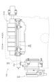
- FIG. 2 is a perspective view of the integrated unit.
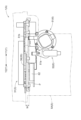
- FIG. 2 is a partial cross-sectional view of the integrated unit.
- FIG. 1 is a schematic diagram showing a cooling system according to a first embodiment.
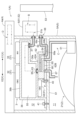
- 1 is a diagram showing a circuit configuration of a cooling system according to a first embodiment.
- FIG. 2 is a schematic diagram showing a flow of a coolant in the cooling system of the first embodiment.
- FIG. FIG. 2 is a diagram showing the configuration of the upper and lower surfaces of the oil cooler.
- FIG. 11 is a schematic diagram showing a cooling system according to a second embodiment.
- FIG. 13 is a schematic diagram showing a cooling system according to a third embodiment.
- FIG. 13 is a schematic diagram showing a cooling system according to a fourth embodiment.
- FIG. 1 is a schematic diagram showing a cooling system according to a first embodiment.
- 1 is a diagram showing a circuit configuration of a cooling system according to a first embodiment.
- FIG. 2 is a schematic diagram showing
- FIG. 13 is a schematic diagram showing a cooling system according to a fourth embodiment.
- FIG. 13 is a diagram showing a circuit configuration of a cooling system according to a fourth embodiment.
- FIG. 2 is a side view of a water-cooled plate housed in an integrated unit.
- FIG. 2 is a perspective view of a water-cooled plate to which an oil cooler is attached.
- FIG. 13 is a partial perspective cross-sectional view of an integrated unit according to a fourth embodiment.
- FIG. 13 is a partial side view of the integrated unit of the fourth embodiment.
- FIG. 13 is a partial side view of the integrated unit of the fourth embodiment.
- FIG. 13 is a schematic diagram showing a cooling system according to a fifth embodiment.
- An electric vehicle is equipped with an electric vehicle drive unit that drives the wheels using current supplied from a battery.
- electric vehicles include vehicles that have a motor as a driving source, such as hybrid electric vehicles (HEVs), plug-in hybrid electric vehicles (PHEVs), battery electric vehicles (BEVs), and fuel cell electric vehicles (FCEVs).
- HEVs hybrid electric vehicles
- PHEVs plug-in hybrid electric vehicles
- BEVs battery electric vehicles
- FCEVs fuel cell electric vehicles
- the electric vehicle includes an integrated unit 1 shown in FIG. 1 and FIG. 2.
- the integrated unit 1 includes an electric vehicle drive unit 2 (hereinafter referred to as the "vehicle drive unit 2"), an electronic circuit unit 3, and a cooling module 4.
- the vehicle drive unit 2 and the electronic circuit unit 3 are housed and integrated in a unit case 5 (an example of a housing).
- the cooling module 4 is disposed adjacent to the electronic circuit unit 3. In the example shown in FIG.
- a chiller 86 for example, as shown in FIG. 1
- a water-cooled condenser 81 for example, a water-cooled condenser 81
- an accumulator 82 for example, a water-cooled condenser 81
- auxiliary equipment such as valves and pumps, which will be described later
- a part of a cooling flow path B and a refrigerant flow path D are modularized and housed in the unit case 5.
- the cooling system A in the present embodiment shown below shows an example in which only the vehicle drive unit 2 and the electronic circuit unit 3 are housed in the unit case 5, but the shape and structure of the integrated unit 1 are not particularly limited. In the following figures, for example, as shown in FIG.
- the traveling direction of the vehicle front-rear direction of the vehicle
- the width direction of the vehicle left-right direction of the vehicle
- the height direction of the vehicle may be referred to as the Z direction
- the front side of the vehicle in the traveling direction may be referred to as the X1 side
- the rear side in the traveling direction as the X2 side
- the left side in the vehicle width direction as the Y1 side
- the right side in the vehicle width direction as the Y2 side.
- the vehicle drive unit 2 includes at least an electric motor 21 that transmits a drive torque to the vehicle's running system.
- the vehicle drive unit 2 includes the electric motor 21, a gear 22 with a reduction mechanism, and the like.
- the electronic circuit unit 3 includes at least an electronic circuit 31 for driving the electric motor 21.
- the electronic circuit unit 3 is housed in a unit case 5 to form a power supply module 100, and a plurality of electronic components that constitute the electronic circuit 31, such as an on-board charger (OBC) 32 (an example of a voltage conversion circuit) and an inverter (INV) 33, are mounted on a board 35.
- OBC on-board charger
- ISV inverter
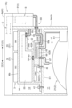
- the cooling system A is configured with an integrated unit 1 in which a vehicle drive unit 2 and an electronic circuit unit 3 are integrated, a cooling flow path B that circulates coolant to the electronic circuit unit 3 (power supply module 100), an oil flow path C that circulates oil to the vehicle drive unit 2, and a refrigerant flow path D that circulates refrigerant for heating and cooling the vehicle interior.
- Cooling flow path B carries coolant such as antifreeze mainly composed of ethylene glycol, long-life coolant, and insulating oil.
- Refrigerant such as hydrofluorocarbon (HFC) flows through refrigerant flow path D.
- HFC hydrofluorocarbon
- the electronic circuit unit 3 is disposed on the upper part of the unit case 5 and fixed to the support body S.
- the vehicle drive unit 2 is disposed below the support body S.
- the arrangement of the vehicle drive unit 2 and the electronic circuit unit 3 is not limited to this, and the vehicle drive unit 2 and the electronic circuit unit 3 may be arranged in the X direction or Y direction, or the vehicle drive unit 2 may be arranged above and the electronic circuit unit 3 below.
- the cooling module 4 is disposed adjacent to the electronic circuit unit 3. Specifically, a refrigerant manifold 4a is disposed on the upper part of the unit case 5, and a water-cooled condenser 81 is disposed on the side of the refrigerant manifold 4a. On the side surface 5A of the unit case 5 and below the water-cooled condenser 81, a valve unit 6 is disposed that is integrated with a water pump 51 and a valve 52 (see FIG. 4) disposed in the cooling flow path B.
- the cooling flow path B is a flow path shown above the electric motor 21 in Figures 3 and 4.
- the cooling flow path B includes the valve unit 6, the power module 100, an oil cooler 62 (an example of a heat exchanger) described below, a water-cooled condenser 81, a radiator 53, etc. along the way.
- the cooling flow path B has a first flow path 54 that runs from the water-cooled condenser 81 to the radiator 53, and a second flow path 55 that runs from the radiator 53 to the water-cooled condenser 81.
- a portion of the second flow path 55 of the cooling flow path B is formed as an internal flow path of the cooling plate 36.
- a portion of the cooling flow path B is disposed inside the unit case 5.
- the cooling flow path B circulates the coolant through the power supply module 100 (electronic circuit unit 3), oil cooler 62, water-cooled condenser 81, and radiator 53 in that order.
- a valve 52 (an example of a three-way valve) is arranged in a first flow path 54 that supplies the coolant to the radiator 53, and can be switched between a first state in which the coolant flows through the radiator 53 and a second state in which the coolant is blocked from flowing into the radiator 53 and diverted.
- the cooling flow path B can be switched by the valve 52 between a flow path 56 in which the coolant passes through the radiator 53 and merges with the second flow path 55, and a flow path 57 in which the coolant flows without passing through the radiator 53 and merges with the second flow path 55.
- the water pump 51 is arranged downstream of the valve 52 and the radiator 53.
- the cooling flow path B has a flow path 58 that runs from the electronic circuit unit 3 to the oil cooler 62, and a flow path 59 that runs from the oil cooler 62 to the water-cooled condenser 81.
- Oil flow path C is the flow path shown below the electronic circuit unit 3 in Figures 3 and 4.
- Oil flow path C has an oil pump 61 and an oil cooler 62 (an example of a heat exchanger) in the middle of the flow path, and supplies oil to the electric motor 21 etc. to circulate the oil to the vehicle drive unit 2.
- the oil cooler 62 is also located downstream of the power supply module 100 (electronic circuit unit 3) in the cooling flow path B, and exchanges heat with the coolant circulating through the cooling flow path B.
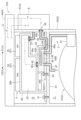
- the refrigerant flow path D is the flow path shown on the right side in FIG. 4, and is configured to circulate a refrigerant for heating and cooling.
- the refrigerant flow path D includes a heating flow path 71 that circulates a refrigerant for heating the vehicle interior, a cooling flow path 72 that circulates a refrigerant for cooling the vehicle interior, and a battery cooling flow path 73 that circulates a refrigerant to cool the battery 87 mounted on the vehicle.
- the heating flow path 71 includes a water-cooled condenser 81, an accumulator 82, a compressor 83, and a cabin condenser 84 (heating condenser) arranged in this order to form a heat pump as a whole.
- the refrigerant flow path D includes a water-cooled condenser 81 in the middle of the flow path that exchanges heat with the cooling liquid circulating in the cooling flow path B.
- the water-cooled condenser 81 is also located downstream of the oil cooler 62 in the cooling flow path B, and exchanges heat with the cooling liquid circulating in the cooling flow path B.
- an on-off valve 91 is disposed in the flow path 74 between the water-cooled condenser 81 and the accumulator 82, and a first expansion valve 92 is disposed in the flow path 76 between the cabin condenser 84 and the water-cooled condenser 81.
- the compressor 83 and cabin condenser 84, and the flow path 75 passing through them, are disposed outside the unit case 5.
- the cooling flow path 72 is composed of a flow path 77 that branches off from the flow path 74 upstream of the on-off valve 91.
- the flow path 77 is configured to have a second expansion valve 93 and an evaporator 85, in that order, midway through the flow path, and to merge with the flow path 74 downstream of the on-off valve 91.
- the second expansion valve 93 is driven with the on-off valve 91 closed, refrigerant flows through the flow path 77, and the evaporator 85 cools the passenger compartment.
- the evaporator 85 is located outside the unit case 5 in the cooling flow path 72.
- the battery cooling flow path 73 is composed of a flow path 78 that branches off from the upstream side of the second expansion valve 93 of the flow path 77 of the cooling flow path 72.
- the flow path 78 is configured to have a third expansion valve 94 and a chiller 86 in sequence in the middle of the flow path, and to merge with the downstream side of the evaporator 85 of the flow path 77.
- the third expansion valve 94 is driven with the opening/closing valve 91 closed, the refrigerant flows through the flow path 78, and the chiller 86 exchanges heat between the refrigerant and the cooling liquid circulating through the cooling circuit 79.
- the opening/closing valve 91, the first expansion valve 92, the second expansion valve 93, and the third expansion valve 94 are preferably modularized and integrated with the cooling module 4, and are preferably housed inside the cooling module 4.
- the battery cooling flow path 73 is configured by arranging the chiller 86 in a cooling circulation path 79 through which coolant circulates between the battery 87 and the chiller 86.
- a water pump 88 is arranged midway along the cooling circulation path 79.
- the battery 87 is arranged, for example, in the underfloor space of the vehicle interior, located outside and rearward of the unit case 5.
- an integrated unit 1 is provided that integrates the vehicle drive unit 2 and the electronic circuit unit 3 (power supply module 100), making it possible to achieve a smaller size than when the vehicle drive unit 2 and the electronic circuit unit 3 (power supply module 100) are arranged separately.
- the oil cooler 62 which exchanges heat between the coolant and oil, allows the waste heat of the vehicle drive unit 2 to be recovered by the coolant.
- the oil cooler 62 is disposed between the vehicle drive unit 2 and the electronic circuit unit 3 (power supply module 100) inside the integrated unit 1.
- the oil cooler 62 is disposed, for example, below the electronic circuit unit 3, and is provided downstream of the second flow path 55 formed inside the cooling plate 36. This makes it possible to perform heat exchange between the oil circulating through the oil flow path C inside the integrated unit 1 and the coolant circulating through the cooling flow path B, thereby improving the heat recovery rate. It also makes it possible to shorten the length of the piping exposed to the outside from the oil cooler 62 in the cooling flow path B.
- the cooling system A of this embodiment can prevent the waste heat of the vehicle drive unit 2 from radiating from the cooling piping, enabling efficient heat management while achieving compact size.
- the electronic circuit 31 of the electronic circuit unit 3 includes an inverter (INV) 33 that controls the current supplied from the battery 87 to the electric motor 21, and an on-board charger (OBC) 32 that controls the voltage to be charged to the battery 87.
- the inverter 33 is disposed on the top of the electronic circuit unit 3
- the on-board charger 32 is disposed on the top and bottom of the electronic circuit unit 3.
- the cooling system A can be further miniaturized. Note that the arrangement of the electronic circuit 31 implemented in the electronic circuit unit 3 shown in FIG. 3 is one example, and the arrangement of the electronic circuit 31 can be changed as appropriate.
- the oil cooler 62 is formed in a box shape having, for example, an upper surface 62A on the side of the electronic circuit 31 and a lower surface 62B on the side of the electric motor 21.
- a cooling liquid inlet section 63 through which the cooling liquid flows in from above is provided on the upper surface 62A
- a cooling liquid outlet section 64 through which the cooling liquid flows out by extending toward the side of the oil cooler 62 is provided on the lower surface 62B.
- the cooling liquid outlet section 64 has a first portion 64A that bends from the lower surface 62B toward the upper surface 62A, and a second portion 64B that is provided continuously with the first portion 64A and runs along the upper surface 62A, and is configured so that the cooling liquid can flow out from the side of the oil cooler 62 to the outside of the electronic circuit unit 3 (power supply module 100).
- the flow path 59 that connects the cooling liquid outlet 64 of the oil cooler 62 to the water-cooled condenser 81 is formed to penetrate the side surface 5A of the unit case 5 and is arranged along the outside of the valve unit 6.
- the cooling fluid piping connected to the oil cooler 62 does not occupy a large area in the height direction of the oil cooler 62, and the integrated unit 1 can be made compact even when the oil cooler 62 is placed between the vehicle drive unit 2 and the electronic circuit unit 3 (power supply module 100).
- the oil cooler 62 has an oil inlet 65 through which the oil flows in and an oil outlet 66 through which the oil flows out, both on the underside 62B. This allows the integrated unit 1 to be made compact even when the oil cooler 62 is disposed between the vehicle drive unit 2 and the electronic circuit unit 3 (power supply module 100).
- the oil outlet 66 of the oil cooler 62 is connected to a supply unit 67 that supplies oil toward the electric motor 21, and is arranged so that the oil flowing out from the supply unit 67 flows out from the lower surface 62B of the oil cooler 62 toward the electric motor 21. In this way, the oil can flow out from the lower surface 62B of the oil cooler 62 toward the electric motor 21.
- a valve unit 6 (cooling manifold) in which a part of the cooling flow path B is formed inside the housing may be integrally assembled to the integrated unit 1.
- the water-cooled condenser 81 and the valve unit 6 are integrated, and a flow path 59 from the oil cooler 62 to the water-cooled condenser 81 and a part of the first flow path 54 from the water-cooled condenser 81 to the valve 52 and the water pump 51 are provided inside the valve unit 6 to form a manifold.
- an integrated unit 1 is provided that integrates the vehicle drive unit 2 and the electronic circuit unit 3 (power supply module 100), making it possible to achieve a smaller size than when the vehicle drive unit 2 and the electronic circuit unit 3 (power supply module 100) are arranged separately.
- an oil cooler 62 is provided that exchanges heat between the coolant and oil
- a water-cooled condenser 81 is provided that exchanges heat between the coolant and refrigerant.
- the temperature of the coolant changes by utilizing the waste heat from the vehicle drive unit 2 in the oil cooler 62 and by utilizing the heat of the refrigerant in the water-cooled condenser 81.
- valve unit 6, in which a portion of the cooling flow path B is formed inside the housing, is integrally assembled with the integrated unit 1.
- a portion of the cooling flow path B, through which the coolant circulates to exchange heat between the oil and the refrigerant, is integrated with the integrated unit 1.
- the cooling system A of this embodiment also enables efficient heat management while being compact.
- valve unit 6, in which part of the cooling flow path B is formed inside the housing is arranged on the side of the electronic circuit unit 3 (power supply module 100).
- the valve unit 6 By arranging the valve unit 6 on the side of the electronic circuit unit 3, it is possible to design the cooling piping of the cooling flow path B extending from the oil cooler 62 arranged close to the vehicle drive unit 2 adjacent to the electronic circuit unit 3 so that it is not exposed to the outside. As a result, it is possible to prevent waste heat from the vehicle drive unit 2 from being dissipated from the cooling piping of the cooling flow path B.
- the water-cooled condenser 81 is integrally assembled to the valve unit 6, and a cooling flow path B that communicates with the water-cooled condenser 81 is formed inside the valve unit 6.
- the oil cooler 62 is disposed on a side surface 5A of the unit case 5, and the water-cooled condenser 81, the valve unit 6, and the oil cooler 62 are integrally assembled to the integrated unit 1. Inside the valve unit 6, a flow path of the cooling flow path B that communicates with the water-cooled condenser 81 and the oil cooler 62 is formed.
- a flow path 58 from the electronic circuit unit 3 (power supply module 100) toward the oil cooler 62, a flow path 59 from the oil cooler 62 toward the water-cooled condenser 81, and a part of the first flow path 54 from the water-cooled condenser 81 toward the valve 52 and the water pump 51 are provided to form a manifold.
- the integrated unit 1 has a first space 11 in which the vehicle drive unit 2 is disposed, a second space 12 in which the electronic circuit unit 3 is disposed, and a partition wall S1 that partitions the first space 11 and the second space 12. That is, the integrated unit 1 is partitioned by the partition wall S1 into the first space 11 at the bottom and the second space 12 at the top.
- the electronic circuit unit 3 is disposed on top of the unit case 5 and fixed to the partition wall S1.
- the vehicle drive unit 2 is disposed below the partition wall S1.
- the cooling module 4 is disposed adjacent to the electronic circuit unit 3.
- a refrigerant manifold 4a is disposed on the top of the unit case 5, and a water-cooled condenser 81 is attached to a side surface 5A (an example of an outer surface) of the unit case 5.
- the integrated unit 1 has a cooling module 4 in which the refrigerant manifold 4a, which includes a refrigerant flow path D through which the refrigerant flows, and the water-cooled condenser 81 are integrated.
- the refrigerant manifold 4a is located above the water-cooled condenser 81.
- the valve unit 6 is disposed on the side surface 5A of the unit case 5.
- the water-cooled condenser 81 is located on the left side (Y1 direction side) of the front side (X1 direction side), and the valve unit 6 is located on the right side (Y2 direction side) of the front side (X1 direction side).
- the second space 12 of the unit case 5 houses a cooling plate 36 for cooling the power supply module 100 and the electronic circuit unit 3.
- the cooling plate 36 is made of a metal with high thermal conductivity such as aluminum, and is integrally formed by joining a plate-shaped lower plate 36a and an upper plate 36b by a method such as welding.
- a space is formed inside the cooling plate 36 (between the lower plate 36a and the upper plate 36b), and a coolant flows through this space.
- the second flow path 55 of the cooling plate 36 is arranged horizontally.
- the cooling liquid flows in through the inlet 37 of the cooling plate 36 and flows out through the outlet 38.
- the oil cooler 62 is engaged with the cooling plate 36 in a concave-convex manner while being disposed in the second space 12.
- the outlet 38 formed in the lower plate 36a of the cooling plate 36 is a cylindrical portion protruding downward, and the outlet 38 of the cooling plate 36 is inserted and fitted into the cooling liquid inlet 63 of the oil cooler 62.
- the cooling liquid inlet 63 of the oil cooler 62 may be configured as a cylindrical portion protruding upward, and the outlet 38 of the cooling plate 36 may be configured as an opening.
- the cooling liquid inlet 63 (cylindrical portion) of the oil cooler 62 is inserted and fitted into the outlet 38 of the cooling plate 36.
- the oil cooler 62 has a support plate P joined to its lower surface 62B, and is positioned relative to the partition wall S1 and fastened to the partition wall S1 by screw members 40 or the like (see also FIG. 10).
- the electronic circuit unit 3, including the cooling plate 36, is also positioned relative to the partition wall S1 and fastened to the partition wall S1 by screw members 41 or the like (see also FIG. 10).
- the oil cooler 62 has a coolant inlet 63 and a coolant outlet 64, an oil inlet 65 and an oil outlet 66, which are arranged diagonally on a plane projected along the lower plate 36a of the cooling plate 36.
- the coolant inlet 63 is arranged closer to the X1 direction and the Y1 direction
- the coolant outlet 64 is arranged closer to the X2 direction and the Y2 direction.
- the oil inlet 65 is arranged closer to the X2 direction and the Y1 direction
- the oil outlet 66 is arranged closer to the X1 direction and the Y2 direction.
- the oil cooler 62 and the water-cooled condenser 81 are arranged in positions facing each other across the wall (side surface 5A) of the unit case 5. As shown in FIG. 9, the water-cooled condenser 81 is attached to a position on the side surface 5A of the unit case 5 close to the oil cooler 62. A flow path 68 is provided between the cooling liquid outlet 64 and the water-cooled condenser 81. In the example shown in FIG.
- the flow path 68 is configured to have a first portion 68a formed along the wall surface of the partition wall S1, a second portion 68b bending from the lower surface 62B toward the upper surface 62A, and a third portion 68c extending in the same direction as the first portion 68a and continuing to the inside and outside of the unit case 5. That is, the third portion 68c is formed to penetrate the side surface 5A of the unit case 5 and is connected to the inside of the water-cooled condenser 81.
- the flow path portion 68 may be configured to have only a first portion 68a that runs along the partition wall S1 between the cooling liquid outlet portion 64 of the oil cooler 62 and the water-cooled condenser 81, without having a second portion 68b and a third portion 68c.
- the piping section (flow path 68) for the cooling liquid connected to the oil cooler 62 does not occupy a large area in the height direction of the oil cooler 62, and the integrated unit 1 can be made compact even when the oil cooler 62 is placed between the vehicle drive unit 2 and the electronic circuit unit 3 (power supply module 100).
- the water pump 51 is fixed to the side surface 5A of the unit case 5 in a position where it overlaps at least a portion of the cooling plate 36 in a side view. As shown in Figure 10, the water pump 51 is disposed on the same side as the radiator 53 with respect to the integrated unit 1.
- the water pump 51 has a coolant intake port 51a and a coolant discharge port 51b, and is positioned so that the coolant discharge port 51b overlaps at least a portion of the cooling plate 36 in a side view. Specifically, the coolant discharge port 51b of the water pump 51 is located within the vertical width W of the cooling plate 36.
- connection flow path 39 is provided below the cooling plate 36 and is formed along the bottom surface (lower plate 36a) of the cooling plate 36.
- the refrigerant manifold 4a and the water-cooled condenser 81 are integrated and disposed outside the unit case 5.
- the refrigerant manifold 4a and the water-cooled condenser 81 may be separated, and the refrigerant manifold 4a and the water-cooled condenser 81 may be individually assembled to the integrated unit 1.
- Fig. 17 shows that the refrigerant manifold 4a and the water-cooled condenser 81 may be individually assembled to the integrated unit 1.
- the integrated unit 1 has the refrigerant manifold 4a including the refrigerant flow path D through which the refrigerant flows, located above and separated from the water-cooled condenser 81, and the water-cooled condenser 81 is connected to the unit case 5 from a lateral side.
- the piping length between the oil cooler 62 and the water-cooled condenser 81 can be shortened, making the integrated unit 1 compact.
- the flow direction of the cooling liquid and refrigerant that exchange heat, and the flow direction of the cooling liquid and oil may be either the same direction or opposite directions.
- the vehicle drive unit 2 and the electronic circuit unit 3 are housed in the unit case 5 and integrated together, but the vehicle drive unit 2 and the electronic circuit unit 3 may be housed in different cases and connected together.
- the oil cooler 62 has the cooling liquid inlet 63 provided on the upper surface 62A and the cooling liquid outlet 64 provided on the lower surface 62B.
- the oil cooler 62 may have both the cooling liquid inlet 63 and the cooling liquid outlet 64 provided on the upper surface 62A.
- the cooling system A is characterized by the following configuration: an integrated unit 1 that integrates an electric vehicle drive unit 2 including at least an electric motor 21 that transmits drive torque to the vehicle's running system, and an electronic circuit unit 3 including at least an electronic circuit 31 for driving the electric motor 21; a cooling flow path B that circulates coolant through the electronic circuit unit 3; and an oil flow path C that has a heat exchanger (oil cooler 62) that exchanges heat with the coolant circulating through the cooling flow path B and circulates oil through the electric vehicle drive unit 2, and the heat exchanger (oil cooler 62) is disposed inside the integrated unit 1 between the electric vehicle drive unit 2 and the electronic circuit unit 3.
- an integrated unit 1 that integrates an electric vehicle drive unit 2 including at least an electric motor 21 that transmits drive torque to the vehicle's running system, and an electronic circuit unit 3 including at least an electronic circuit 31 for driving the electric motor 21
- a cooling flow path B that circulates coolant through the electronic circuit unit 3
- an oil flow path C that has a heat exchanger (oil cooler
- the integrated unit 1 is provided with the electric vehicle drive unit 2 and the electronic circuit unit 3 integrated together, so the integrated unit 1 can be made smaller than when the electric vehicle drive unit 2 and the electronic circuit unit 3 are arranged separately.
- the heat exchanger oil cooler 62
- the waste heat of the electric vehicle drive unit 2 and the heat generated by the electronic circuit unit 3 allows the waste heat of the electric vehicle drive unit 2 and the heat generated by the electronic circuit unit 3 to be recovered by the coolant.
- the heat exchanger (oil cooler 62) is placed inside the integrated unit 1, between the electric vehicle drive unit 2 and the electronic circuit unit 3. This makes it possible to exchange heat between the oil and the coolant inside the integrated unit 1, improving the heat recovery rate. It also makes it possible to shorten the length of the piping in the cooling flow path B that is exposed to the outside from the heat exchanger (oil cooler 62).
- the cooling system A described in (1) further includes a cooling plate 36 to which the electronic circuit unit 3 is fixed and through which a coolant flows, and that the heat exchanger (oil cooler 62) is disposed between the electric vehicle drive unit 2 and the cooling plate 36.
- a heat exchanger (oil cooler 62) is placed inside the integrated unit 1, between the electric vehicle drive unit 2 and the cooling plate 36. This makes it possible to exchange heat between the oil and the coolant inside the integrated unit 1, improving the heat recovery rate. It also makes it possible to shorten the length of the piping exposed to the outside from the heat exchanger (oil cooler 62) in the cooling flow path B.
- the heat exchanger (oil cooler 62) is arranged below the cooling plate 36.
- This configuration allows the coolant to flow smoothly from the cooling plate 36 to the heat exchanger (oil cooler 62), making it possible to shorten the length of the piping between the cooling plate 36 and the heat exchanger (oil cooler 62).
- the integrated unit 1 includes an electric vehicle drive unit 2 and an electronic circuit unit 3 housed in a housing (unit case 5).
- the electric vehicle drive unit 2 and the electronic circuit unit 3 are integrated and housed in a housing (unit case 5), making it possible to reduce the size of the integrated unit 1.
- the electronic circuit 31 includes an inverter 33 that controls the current supplied from the battery 87 to the electric motor 21, and a voltage conversion circuit that controls the voltage charged to the battery 87.
- the electronic circuit 31 included in the electronic circuit unit 3 includes not only the inverter 33 but also a voltage conversion circuit, further miniaturization can be achieved.
- the heat exchanger (oil cooler 62) has an oil inlet 65 through which oil flows in and an oil outlet 66 through which oil flows out, separately on the underside 62B on the electric motor 21 side.
- the integrated unit 1 can be made compact even when the heat exchanger (oil cooler 62) is placed between the electric vehicle drive unit 2 and the electronic circuit unit 3.
- the heat exchanger (oil cooler 62) has a cooling liquid inlet 63 through which the cooling liquid flows on the upper surface 62A on the cooling plate 36 side, and a cooling liquid outlet 64 through which the cooling liquid flows out, an oil inlet 65, and an oil outlet 66 on the lower surface 62B on the electric motor 21 side.
- the heat exchanger (oil cooler 62) is configured so that oil flows in and out from the lower surface 62B, and the heat exchanger (oil cooler 62) has a coolant inlet 63 on the upper surface 62A and a coolant outlet 64 on the lower surface 62B, so that the integrated unit 1 can be made compact even when the heat exchanger (oil cooler 62) is disposed between the electric vehicle drive unit 2 and the electronic circuit unit 3.
- the oil flows out from the lower surface 62B of the heat exchanger (oil cooler 62) toward the electric motor 21, thereby effectively cooling the electric motor 21.
- the heat exchanger (oil cooler 62) has a coolant outlet 64 extending from the underside 62B on the electric motor 21 side through which the coolant flows out, and it is preferable that the cooling flow path B leading from the coolant outlet 64 to the outside of the electronic circuit unit 3 is positioned below the upper surface 62A on the cooling plate 36 side of the heat exchanger (oil cooler 62).
- the cooling flow path B in the heat exchanger (oil cooler 62) that runs from the coolant outlet 64 to the outside of the electronic circuit unit 3 is positioned below the upper surface 62A of the heat exchanger (oil cooler 62) on the cooling plate 36 side, the cooling piping does not occupy the heat exchanger (oil cooler 62) in the height direction, and the integrated unit 1 can be made compact even when the heat exchanger (oil cooler 62) is positioned between the electric vehicle drive unit 2 and the cooling plate 36.
- the coolant outflow section 64 preferably has a first portion 68a that bends from the lower surface 62B toward the upper surface 62A, and a second portion 68b that is continuous with the first portion 68a and runs along the upper surface 62A, and is configured so that the coolant can flow out from the side of the heat exchanger (oil cooler 62) to the outside of the electronic circuit unit 3.
- the coolant outflow section 64 has a first portion 68a that bends from the lower surface 62B toward the upper surface 62A and a second portion 68b that is continuous with the first portion 68a and runs along the upper surface 62A, and the coolant can flow out from the side of the heat exchanger (oil cooler 62) to the outside of the electronic circuit unit 3, the cooling piping does not occupy the heat exchanger (oil cooler 62) in the height direction, and the integrated unit 1 can be made compact even when the heat exchanger (oil cooler 62) is placed between the electric vehicle drive unit 2 and the cooling plate 36.
- This configuration allows heat exchange between the oil and the cooling fluid inside the integrated unit 1, improving the heat recovery rate. It also makes it possible to shorten the piping length between the heat exchanger (oil cooler 62) and the cooling plate 36 in the flow path through which the cooling fluid flows. This makes it possible to prevent the waste heat of the electric vehicle drive unit 2 from being dissipated from the cooling piping, resulting in a cooling system A that is compact yet allows for efficient heat management.
- the cooling plate 36 has a cylindrical outlet 38 protruding toward the heat exchanger (oil cooler 62), and the heat exchanger (oil cooler 62) has a cooling liquid inlet 63 on the upper surface 62A on the cooling plate 36 side, through which the cooling liquid flows, and it is preferable that the outlet 38 is fitted into the cooling liquid inlet 63.
- the cylindrical outlet 38 of the cooling plate 36 fits into the coolant inlet 63 of the heat exchanger (oil cooler 62), so there is no need to install piping between the cooling plate 36 and the heat exchanger (oil cooler 62). This makes it possible to reduce the number of parts and make the integrated unit 1 more compact.
- the heat exchanger (oil cooler 62) has a cylindrical cooling liquid inlet 63 that protrudes from the upper surface 62A on the cooling plate 36 side, into which the cooling liquid flows, and it is preferable that the cooling liquid inlet 63 is fitted into the outlet 38 of the cooling plate 36.
- the outlet 38 of the cooling plate 36 fits into the cylindrical coolant inlet 63 of the heat exchanger (oil cooler 62), so there is no need to install piping between the cooling plate 36 and the heat exchanger (oil cooler 62). This makes it possible to reduce the number of parts and make the integrated unit 1 more compact.
- the integrated unit 1 has a partition wall S1 that separates a first space 11 in which the electric vehicle drive unit 2 is arranged from a second space 12 in which the electronic circuit unit 3 is arranged, and it is preferable that the heat exchanger (oil cooler 62) is arranged in the second space 12.
- the integrated unit 1 has a partition wall S1 that separates the first space 11 in which the electric vehicle drive unit 2 is arranged from the second space 12 in which the electronic circuit unit 3 is arranged, so that the electric vehicle drive unit 2 and the electronic circuit unit 3 can be easily arranged in predetermined positions in the integrated unit 1.
- the heat exchanger oil cooler 62
- the cooling plate 36 can be easily engaged with each other.
- the integrated unit 1 can be made even smaller. Also, by fastening the heat exchanger (oil cooler 62) to the partition wall S1, the heat exchanger (oil cooler 62) can be assembled from above the integrated unit 1.
- the integrated unit 1 has a support plate P that supports the heat exchanger (oil cooler 62), and that the heat exchanger (oil cooler 62) is positioned relative to the partition wall S1 by the support plate P.
- the support plate P determines the position of the heat exchanger (oil cooler 62) relative to the partition wall S1, so that the heat exchanger (oil cooler 62) can be installed with high precision relative to the partition wall S1. This allows the heat exchanger (oil cooler 62) to be installed in a position that allows the piping length to be shortened, making it possible to reduce the size of the integrated unit 1.
- the cooling system A is characterized by the integrated unit 1, which is an integrated unit of an electric vehicle drive unit 2 including at least an electric motor 21 that transmits drive torque to the vehicle's running system, and an electronic circuit unit 3 including at least an electronic circuit 31 for driving the electric motor 21, a cooling flow path B that circulates a coolant through the electronic circuit unit 3, an oil flow path C that has a heat exchanger (oil cooler 62) that exchanges heat with the coolant circulating through the cooling flow path B and circulates oil through the electric vehicle drive unit 2, and a refrigerant flow path D that has a water-cooled condenser 81 that exchanges heat with the coolant circulating through the cooling flow path B and circulates a refrigerant for heating and cooling, and a cooling manifold (valve unit 6) in which a part of the cooling flow path B is formed inside the housing is integrally assembled to the integrated unit 1.
- the integrated unit 1 is an integrated unit of an electric vehicle drive unit 2 including at least an electric motor 21 that transmits drive torque to the vehicle's running
- an integrated unit 1 is provided that integrates the electric vehicle drive unit 2 and the electronic circuit unit 3, making it possible to achieve a smaller size than when the electric vehicle drive unit 2 and the electronic circuit unit 3 are arranged separately.
- a heat exchanger oil cooler 62
- a water-cooled condenser 81 is provided to exchange heat between the coolant and refrigerant.
- the temperature of the coolant changes by utilizing the waste heat from the electric vehicle drive unit 2 in the heat exchanger (oil cooler 62) and by utilizing the heat of the refrigerant in the water-cooled condenser 81.
- the cooling manifold (valve unit 6), in which part of the cooling flow path B is formed inside the housing, is integrally assembled with the integrated unit 1.
- part of the cooling flow path B through which the coolant circulates to exchange heat between the oil and the refrigerant, is integrated with the integrated unit 1.
- cooling system A is compact yet capable of efficient heat management.
- cooling manifold (valve unit 6) is arranged on the side of the electronic circuit unit 3.
- the water-cooled condenser 81 is integrally assembled to the cooling manifold (valve unit 6).
- the heat exchanger (oil cooler 62) is disposed inside the integrated unit 1 between the electric vehicle drive unit 2 and the electronic circuit unit 3.
- the present invention can be widely used in cooling systems for electric vehicles.
Landscapes
- Engineering & Computer Science (AREA)
- Mechanical Engineering (AREA)
- Chemical & Material Sciences (AREA)
- Combustion & Propulsion (AREA)
- General Engineering & Computer Science (AREA)
- Physics & Mathematics (AREA)
- Thermal Sciences (AREA)
- Transportation (AREA)
- Power Engineering (AREA)
- Microelectronics & Electronic Packaging (AREA)
- Electric Propulsion And Braking For Vehicles (AREA)
Abstract
Description
電動自動車は、図1及び図2に示される統合ユニット1を備える。統合ユニット1は、電動車両用駆動ユニット2(以下、「車両用駆動ユニット2」と称する)、電子回路ユニット3、及び、冷却モジュール4を備える。統合ユニット1において、車両用駆動ユニット2及び電子回路ユニット3は、ユニットケース5(筐体の一例)に収容されて一体化されている。冷却モジュール4は、電子回路ユニット3に隣接して配置される。図1に示す例では、冷却モジュール4として、後述するチラー86、水冷コンデンサ81、アキュムレータ82、及び弁やポンプ等の補機類と、冷却流路B及び冷媒流路Dの一部がモジュール化されてユニットケース5に収容されている。以下に示す本実施形態における冷却システムAは、ユニットケース5に車両用駆動ユニット2及び電子回路ユニット3のみが収容された例を示すが、統合ユニット1の形状や構造は特に限定されない。以下の図では、例えば図1に示されるように、車両の進行方向(車両前後方向)をX方向と、車両の幅方向(車両左右方向)をY方向と、車両の高さ方向をZ方向と称する場合がある。また、車両の進行方向前側をX1側、進行方向後側をX2側と、車幅方向左側をY1側、車幅方向右側をY2側と称する場合がある。
第1実施形態では、オイルクーラ62および水冷コンデンサ81の間の流路が外部に露出して配置される例を示した。これに代えて、図7に示されるように、冷却流路Bの一部をハウジングの内部に形成した弁ユニット6(冷却マニホールド)が、統合ユニット1に一体的に組み付けられていてもよい。具体的には、図7に示される例では、水冷コンデンサ81と弁ユニット6とが一体化されており、弁ユニット6の内部に、オイルクーラ62から水冷コンデンサ81に向かう流路59と、水冷コンデンサ81から弁52及びウォータポンプ51に向かう第1流路54の一部とが設けられてマニホールド化されている。
第3実施形態では、図8に示されるように、オイルクーラ62がユニットケース5の側面5Aに配置され、水冷コンデンサ81、弁ユニット6及びオイルクーラ62が、統合ユニット1に一体的に組み付けられている。弁ユニット6の内部には、水冷コンデンサ81及びオイルクーラ62に連通する冷却流路Bの流路が形成されている。具体的には、弁ユニット6の内部に、電子回路ユニット3(電源モジュール100)からオイルクーラ62に向かう流路58と、オイルクーラ62から水冷コンデンサ81に向かう流路59と、水冷コンデンサ81から弁52及びウォータポンプ51に向かう第1流路54の一部とが設けられてマニホールド化されている。
第4実施形態では、図9に示されるように、統合ユニット1は、車両用駆動ユニット2が配置される第1空間11と、電子回路ユニット3が配置されている第2空間12と、第1空間11と第2空間12とを区画する区画壁S1を有する。すなわち、統合ユニット1は、区画壁S1によって下部の第1空間11と上部の第2空間12に区画される。
第4実施形態では、冷媒マニホールド4aと水冷コンデンサ81とが一体となってユニットケース5の外部に配置される例を示した。これに代えて、図17に示されるように、冷媒マニホールド4aと水冷コンデンサ81とが分割され、統合ユニット1に冷媒マニホールド4a及び水冷コンデンサ81が個別に組み付けられていてもよい。具体的には、図17に示されるように、統合ユニット1は、冷媒が流れる冷媒流路Dを含む冷媒マニホールド4aを、水冷コンデンサ81に対して上方且つ分離した状態で有し、水冷コンデンサ81はユニットケース5に対して側方側から接続されている。
(1)上記の実施形態では、冷却流路Bにおいてウォータポンプ51と弁52が一体化されて構成される例を示したが、ウォータポンプ51と弁52が別体で構成されていてもよく、ウォータポンプ51と弁52とが個別のハウジングに収容されていてもよい。
以下、上記において説明した冷却システムAの概要について説明する。
Claims (16)
- 駆動回転力を車両の走行系に伝える電動モータを少なくとも含む電動車両用駆動ユニットと、前記電動モータを駆動するための電子回路を少なくとも含む電子回路ユニットと、が一体化された統合ユニットと、
前記電子回路ユニットに冷却液を循環させる冷却流路と、
前記冷却流路を循環する前記冷却液と熱交換を行う熱交換器を有し、前記電動車両用駆動ユニットにオイルを循環させるオイル流路と、を備え、
前記熱交換器は、前記統合ユニットの内部において、前記電動車両用駆動ユニットと前記電子回路ユニットとの間に配置されている冷却システム。 - 前記電子回路ユニットが固定され、内部に前記冷却液が流通する冷却プレートをさらに備え、
前記熱交換器は、前記電動車両用駆動ユニットと前記冷却プレートとの間に配置されている請求項1に記載の冷却システム。 - 前記熱交換器は、前記冷却プレートの下側に配置されている請求項2に記載の冷却システム。
- 前記統合ユニットは、前記電動車両用駆動ユニットと、前記電子回路ユニットと、が筐体に内蔵されている請求項1から3のいずれか一項に記載の冷却システム。
- 前記電子回路は、バッテリから前記電動モータに供給される電流を制御するインバータと、前記バッテリに充電する電圧を制御する電圧変換回路と、を含んでいる請求項1から3のいずれか一項に記載の冷却システム。
- 前記熱交換器は、前記オイルが流入するオイル流入口と、前記オイルが流出するオイル流出口と、を前記電動モータの側の下面に個別に有する請求項1から3のいずれか一項に記載の冷却システム。
- 前記熱交換器は、前記冷却液が流入する冷却液流入部を、前記冷却プレートの側の上面に有し、
前記冷却液が流出する冷却液流出部と、前記オイルが流入するオイル流入口と、前記オイルが流出するオイル流出口と、を前記電動モータの側の下面に個別に有する請求項2又は3に記載の冷却システム。 - 前記オイルは、前記下面から前記電動モータに向かって流出する請求項6に記載の冷却システム。
- 前記熱交換器は、前記電動モータの側の下面から延出されて前記冷却液が流出する冷却液流出部を有し、
前記冷却液流出部から前記電子回路ユニットの外側へと至る前記冷却流路が、前記熱交換器における前記冷却プレートの側の上面よりも下側に配置されている請求項2又は3に記載の冷却システム。 - 前記冷却液流出部は、前記下面から前記上面に向けて屈曲する第1部分と、前記第1部分に連続して前記上面に沿う第2部分と、を有し、前記冷却液が前記熱交換器の側方から前記電子回路ユニットの外側に流出可能に構成されている請求項9に記載の冷却システム。
- 前記熱交換器は、前記冷却プレートに凹凸係合されている請求項2又は3に記載の冷却システム。
- 前記冷却プレートは、前記熱交換器の側に向かって突出した筒状の流出口を有し、
前記熱交換器は、前記冷却液が流入する冷却液流入部を、前記冷却プレートの側の上面に有しており、
前記流出口は、前記冷却液流入部に嵌合している請求項11に記載の冷却システム。 - 前記熱交換器は、前記冷却液が流入し、前記冷却プレートの側の上面から突出した筒状の冷却液流入部を有しており、
前記冷却液流入部は、前記冷却プレートの流出口に嵌合している請求項11に記載の冷却システム。 - 前記統合ユニットは、前記電動車両用駆動ユニットが配置される第1空間と、前記電子回路ユニットが配置されている第2空間とを区画する区画壁を有し、
前記熱交換器は、前記第2空間に配置されている請求項1から3のいずれか一項に記載の冷却システム。 - 前記熱交換器は、前記区画壁に締結されている請求項14に記載の冷却システム。
- 前記統合ユニットは、前記熱交換器を支持する支持プレートを有し、
前記熱交換器は、前記支持プレートにより前記区画壁に対して位置決めされている請求項15に記載の冷却システム。
Priority Applications (3)
| Application Number | Priority Date | Filing Date | Title |
|---|---|---|---|
| CN202380074227.8A CN120130016A (zh) | 2022-11-16 | 2023-11-10 | 冷却系统 |
| JP2024558828A JPWO2024106330A1 (ja) | 2022-11-16 | 2023-11-10 | |
| EP23891479.0A EP4576519A4 (en) | 2022-11-16 | 2023-11-10 | COOLING SYSTEM |
Applications Claiming Priority (6)
| Application Number | Priority Date | Filing Date | Title |
|---|---|---|---|
| JP2022183674 | 2022-11-16 | ||
| JP2022-183674 | 2022-11-16 | ||
| JP2022-183675 | 2022-11-16 | ||
| JP2022183675 | 2022-11-16 | ||
| JP2023-089637 | 2023-05-31 | ||
| JP2023089637 | 2023-05-31 |
Publications (1)
| Publication Number | Publication Date |
|---|---|
| WO2024106330A1 true WO2024106330A1 (ja) | 2024-05-23 |
Family
ID=91084494
Family Applications (1)
| Application Number | Title | Priority Date | Filing Date |
|---|---|---|---|
| PCT/JP2023/040548 Ceased WO2024106330A1 (ja) | 2022-11-16 | 2023-11-10 | 冷却システム |
Country Status (4)
| Country | Link |
|---|---|
| EP (1) | EP4576519A4 (ja) |
| JP (1) | JPWO2024106330A1 (ja) |
| CN (1) | CN120130016A (ja) |
| WO (1) | WO2024106330A1 (ja) |
Citations (4)
| Publication number | Priority date | Publication date | Assignee | Title |
|---|---|---|---|---|
| JP2004260898A (ja) * | 2003-02-25 | 2004-09-16 | Nissan Motor Co Ltd | 電気自動車の駆動ユニット |
| JP2020178485A (ja) | 2019-04-19 | 2020-10-29 | 日本電産株式会社 | モータユニット |
| JP2021069255A (ja) * | 2019-10-28 | 2021-04-30 | トヨタ自動車株式会社 | 駆動装置 |
| JP2021136833A (ja) * | 2020-02-28 | 2021-09-13 | 日本電産株式会社 | 駆動装置 |
Family Cites Families (1)
| Publication number | Priority date | Publication date | Assignee | Title |
|---|---|---|---|---|
| JP3886697B2 (ja) * | 1999-04-27 | 2007-02-28 | アイシン・エィ・ダブリュ株式会社 | 駆動装置 |
-
2023
- 2023-11-10 EP EP23891479.0A patent/EP4576519A4/en active Pending
- 2023-11-10 WO PCT/JP2023/040548 patent/WO2024106330A1/ja not_active Ceased
- 2023-11-10 JP JP2024558828A patent/JPWO2024106330A1/ja active Pending
- 2023-11-10 CN CN202380074227.8A patent/CN120130016A/zh active Pending
Patent Citations (4)
| Publication number | Priority date | Publication date | Assignee | Title |
|---|---|---|---|---|
| JP2004260898A (ja) * | 2003-02-25 | 2004-09-16 | Nissan Motor Co Ltd | 電気自動車の駆動ユニット |
| JP2020178485A (ja) | 2019-04-19 | 2020-10-29 | 日本電産株式会社 | モータユニット |
| JP2021069255A (ja) * | 2019-10-28 | 2021-04-30 | トヨタ自動車株式会社 | 駆動装置 |
| JP2021136833A (ja) * | 2020-02-28 | 2021-09-13 | 日本電産株式会社 | 駆動装置 |
Non-Patent Citations (1)
| Title |
|---|
| See also references of EP4576519A4 |
Also Published As
| Publication number | Publication date |
|---|---|
| EP4576519A4 (en) | 2025-12-17 |
| EP4576519A1 (en) | 2025-06-25 |
| JPWO2024106330A1 (ja) | 2024-05-23 |
| CN120130016A (zh) | 2025-06-10 |
Similar Documents
| Publication | Publication Date | Title |
|---|---|---|
| KR102942522B1 (ko) | 통합형 전기 구동 시스템 및 전기 차량 | |
| JP7033730B2 (ja) | 冷却装置、電池温度調整システム及び車両 | |
| US11001122B2 (en) | Vehicle power unit temperature regulation system | |
| US12565078B2 (en) | Electric vehicle and thermal manager thereof | |
| JP2024172115A (ja) | 車両駆動装置 | |
| JP2024172114A (ja) | 車両駆動装置 | |
| EP3093587A1 (en) | Transportation refrigeration unit and trailer | |
| JP7507538B2 (ja) | 車両、及び、電池パック | |
| US20250222760A1 (en) | Cooling module | |
| JP2005343221A (ja) | 車両の冷却装置構造 | |
| JP7478922B2 (ja) | 車両、及び、電池パック | |
| WO2024225210A1 (ja) | 車両駆動装置 | |
| WO2024106330A1 (ja) | 冷却システム | |
| JP7207342B2 (ja) | 車両用バッテリパック | |
| JP2004262330A (ja) | 車両用マルチタイプ熱交換器 | |
| KR20130096589A (ko) | 하이브리드 자동차용 일체형 열교환기 | |
| JP2012218680A (ja) | 複合熱交換器 | |
| US20250188863A1 (en) | Water supply module | |
| KR102948590B1 (ko) | 차량용 냉각 모듈 | |
| WO2024106247A1 (ja) | 冷却システム | |
| CN111196181B (zh) | 用于车辆的冷却系统 | |
| JP7426609B2 (ja) | 車両、及び、電池パック | |
| JP2024072693A (ja) | 車両下部構造 | |
| CN220923785U (zh) | 全地形车 | |
| JP7838654B2 (ja) | 車両冷却系構造 |
Legal Events
| Date | Code | Title | Description |
|---|---|---|---|
| 121 | Ep: the epo has been informed by wipo that ep was designated in this application |
Ref document number: 23891479 Country of ref document: EP Kind code of ref document: A1 |
|
| WWE | Wipo information: entry into national phase |
Ref document number: 2024558828 Country of ref document: JP |
|
| WWE | Wipo information: entry into national phase |
Ref document number: 2023891479 Country of ref document: EP |
|
| ENP | Entry into the national phase |
Ref document number: 2023891479 Country of ref document: EP Effective date: 20250320 |
|
| WWE | Wipo information: entry into national phase |
Ref document number: 202380074227.8 Country of ref document: CN |
|
| WWP | Wipo information: published in national office |
Ref document number: 202380074227.8 Country of ref document: CN |
|
| NENP | Non-entry into the national phase |
Ref country code: DE |
|
| WWP | Wipo information: published in national office |
Ref document number: 2023891479 Country of ref document: EP |