WO2024111373A1 - 回転電機 - Google Patents
回転電機 Download PDFInfo
- Publication number
- WO2024111373A1 WO2024111373A1 PCT/JP2023/039471 JP2023039471W WO2024111373A1 WO 2024111373 A1 WO2024111373 A1 WO 2024111373A1 JP 2023039471 W JP2023039471 W JP 2023039471W WO 2024111373 A1 WO2024111373 A1 WO 2024111373A1
- Authority
- WO
- WIPO (PCT)
- Prior art keywords
- stator
- teeth
- rotor
- skew
- angle
- Prior art date
- Legal status (The legal status is an assumption and is not a legal conclusion. Google has not performed a legal analysis and makes no representation as to the accuracy of the status listed.)
- Ceased
Links
Images




Classifications
-
- H—ELECTRICITY
- H02—GENERATION; CONVERSION OR DISTRIBUTION OF ELECTRIC POWER
- H02K—DYNAMO-ELECTRIC MACHINES
- H02K1/00—Details of the magnetic circuit
- H02K1/06—Details of the magnetic circuit characterised by the shape, form or construction
- H02K1/12—Stationary parts of the magnetic circuit
- H02K1/16—Stator cores with slots for windings
-
- H—ELECTRICITY
- H02—GENERATION; CONVERSION OR DISTRIBUTION OF ELECTRIC POWER
- H02K—DYNAMO-ELECTRIC MACHINES
- H02K1/00—Details of the magnetic circuit
- H02K1/06—Details of the magnetic circuit characterised by the shape, form or construction
- H02K1/12—Stationary parts of the magnetic circuit
- H02K1/14—Stator cores with salient poles
- H02K1/146—Stator cores with salient poles consisting of a generally annular yoke with salient poles
- H02K1/148—Sectional cores
-
- H—ELECTRICITY
- H02—GENERATION; CONVERSION OR DISTRIBUTION OF ELECTRIC POWER
- H02K—DYNAMO-ELECTRIC MACHINES
- H02K1/00—Details of the magnetic circuit
- H02K1/06—Details of the magnetic circuit characterised by the shape, form or construction
- H02K1/12—Stationary parts of the magnetic circuit
- H02K1/14—Stator cores with salient poles
-
- H—ELECTRICITY
- H02—GENERATION; CONVERSION OR DISTRIBUTION OF ELECTRIC POWER
- H02K—DYNAMO-ELECTRIC MACHINES
- H02K1/00—Details of the magnetic circuit
- H02K1/06—Details of the magnetic circuit characterised by the shape, form or construction
- H02K1/22—Rotating parts of the magnetic circuit
- H02K1/27—Rotor cores with permanent magnets
- H02K1/2706—Inner rotors
- H02K1/272—Inner rotors the magnetisation axis of the magnets being perpendicular to the rotor axis
- H02K1/274—Inner rotors the magnetisation axis of the magnets being perpendicular to the rotor axis the rotor consisting of two or more circumferentially positioned magnets
- H02K1/2753—Inner rotors the magnetisation axis of the magnets being perpendicular to the rotor axis the rotor consisting of two or more circumferentially positioned magnets the rotor consisting of magnets or groups of magnets arranged with alternating polarity
- H02K1/278—Surface mounted magnets; Inset magnets
-
- H—ELECTRICITY
- H02—GENERATION; CONVERSION OR DISTRIBUTION OF ELECTRIC POWER
- H02K—DYNAMO-ELECTRIC MACHINES
- H02K21/00—Synchronous motors having permanent magnets; Synchronous generators having permanent magnets
- H02K21/12—Synchronous motors having permanent magnets; Synchronous generators having permanent magnets with stationary armatures and rotating magnets
- H02K21/14—Synchronous motors having permanent magnets; Synchronous generators having permanent magnets with stationary armatures and rotating magnets with magnets rotating within the armatures
- H02K21/16—Synchronous motors having permanent magnets; Synchronous generators having permanent magnets with stationary armatures and rotating magnets with magnets rotating within the armatures having annular armature cores with salient poles
-
- H—ELECTRICITY
- H02—GENERATION; CONVERSION OR DISTRIBUTION OF ELECTRIC POWER
- H02K—DYNAMO-ELECTRIC MACHINES
- H02K29/00—Motors or generators having non-mechanical commutating devices, e.g. discharge tubes or semiconductor devices
- H02K29/03—Motors or generators having non-mechanical commutating devices, e.g. discharge tubes or semiconductor devices with a magnetic circuit specially adapted for avoiding torque ripples or self-starting problems
-
- H—ELECTRICITY
- H02—GENERATION; CONVERSION OR DISTRIBUTION OF ELECTRIC POWER
- H02K—DYNAMO-ELECTRIC MACHINES
- H02K3/00—Details of windings
- H02K3/04—Windings characterised by the conductor shape, form or construction, e.g. with bar conductors
- H02K3/28—Layout of windings or of connections between windings
-
- H—ELECTRICITY
- H02—GENERATION; CONVERSION OR DISTRIBUTION OF ELECTRIC POWER
- H02K—DYNAMO-ELECTRIC MACHINES
- H02K2201/00—Specific aspects not provided for in the other groups of this subclass relating to the magnetic circuits
- H02K2201/06—Magnetic cores, or permanent magnets characterised by their skew
-
- H—ELECTRICITY
- H02—GENERATION; CONVERSION OR DISTRIBUTION OF ELECTRIC POWER
- H02K—DYNAMO-ELECTRIC MACHINES
- H02K2213/00—Specific aspects, not otherwise provided for and not covered by codes H02K2201/00 - H02K2211/00
- H02K2213/03—Machines characterised by numerical values, ranges, mathematical expressions or similar information
Definitions
- This disclosure relates to rotating electrical machines.
- Patent Document 1 The rotating electric machine described in Patent Document 1 is known as an example of a rotating electric machine having concentrated winding coils.
- Patent Document 1 describes a rotating electric machine having a specific number of magnetic poles in the rotor and a specific number of slots between the teeth in the stator, specifically, a rotating electric machine with 14 magnetic poles and 18 slots, a rotating electric machine with 22 magnetic poles and 18 slots, a rotating electric machine with 16 magnetic poles and 18 slots, and a rotating electric machine with 20 magnetic poles and 18 slots.
- the phase difference of the magnetomotive force in each coil body between the phases is set within a predetermined phase range including 20 degrees in electrical angle, thereby canceling out the electrical 6th or electrical 12th harmonic components and suppressing torque ripple.
- Patent Document 1 was an application filed by the applicant of the present application, but the applicant further discovered that in a rotating electric machine with the specific number of magnetic poles and slots as described above, the eighth-order electrical component and the tenth-order electrical component generate radial electromagnetic forces in a direction that causes the stator to deform into an ellipse, which in turn generates radial vibrations. In this case, there is concern that the rotating electric machine will produce noise and other inconveniences, and that its quietness will decrease. It has also been confirmed that such radial vibrations occur in rotating electric machines with a specific number of magnetic poles and slots, such as 14 poles and 18 slots, and are not a problem in rotating electric machines with, for example, 8 poles and 12 slots.
- This disclosure was made in consideration of the above problems, and aims to improve quietness in rotating electrical machines that have a specific number of magnetic poles and slots.
- the present disclosure relates to A rotor having a plurality of magnetic poles arranged in a circumferential direction;
- a rotating electric machine including a stator having a stator core having a plurality of teeth in a circumferential direction and a multi-phase stator winding wound around the teeth by concentrated winding,
- the number of magnetic poles of the rotor is (18 ⁇ 4) and the number of slots between the teeth is 18, or
- the number of magnetic poles of the rotor is (18 ⁇ 2), and the number of slots between the teeth is 18;
- the stator or the rotor is skewed to suppress radial vibrations of the eighth and tenth electrical components.
- a skew is applied to at least one of the stator and rotor to suppress radial vibrations of the 8th and 10th electric components.
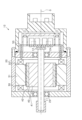
- FIG. 1 is a longitudinal sectional view of a motor
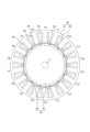
- FIG. 2 is a cross-sectional view of a motor
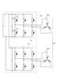
- FIG. 3 is a diagram showing an electrical configuration of the control device
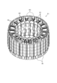
- FIG. 4 is a perspective view of a stator
- FIG. 5 is a perspective view showing a configuration of a stator core
- FIG. 6 is a winding configuration diagram of a stator winding
- FIG. 7 is a diagram showing a correspondence relationship between each partial winding of a stator winding and a tooth
- FIG. 1 is a longitudinal sectional view of a motor
- FIG. 2 is a cross-sectional view of a motor
- FIG. 3 is a diagram showing an electrical configuration of the control device
- FIG. 4 is a perspective view of a stator
- FIG. 5 is a perspective view showing a configuration of a stator core
- FIG. 6 is a winding configuration diagram of a stator winding
- FIG. 7 is a diagram showing a correspondence relationship between each partial wind
- FIG. 8 is a diagram for explaining that radial acceleration is generated by the eighth-order component and the tenth-order component
- FIG. 9 is a perspective view showing a row-to-row skew structure of a stator core
- FIG. 10 is a diagram for explaining the skew angle of the stator core
- FIG. 11 is a diagram showing the relationship between the radial vibration acceleration of the eighth and tenth electrical orders and the skew angle
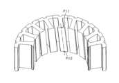
- FIG. 12 is a perspective view showing a linear skew structure of a stator core
- FIG. 13 is a perspective view showing the skew structure of the rotor.
- a motor 10 will be used as an example of a rotating electric machine.
- the motor 10 shown in FIG. 1 is of a permanent magnet field type, and specifically, is a permanent magnet field type synchronous machine with a three-phase winding. In other words, the motor 10 is a brushless motor. This three-phase winding may have two systems.
- the motor 10 comprises a housing 20, a stator 30 fixed to the housing 20, a rotor 40 that rotates relative to the stator 30, and a rotating shaft 11 to which the rotor 40 is fixed.
- the axial direction refers to the axial direction of the rotating shaft 11
- the radial direction refers to the radial direction of the rotating shaft 11
- the circumferential direction refers to the circumferential direction of the rotating shaft 11.
- the housing 20 is formed in a cylindrical shape, and contains the stator 30, rotor 40, etc.
- the housing 20 is provided with bearings 23, 24, which support the rotating shaft 11 so that it can rotate freely.
- the axis of the inner circumferential surface of the housing 20 is coaxial with the rotating shaft 11.
- An angle sensor 12 is provided on the tip side of the rotating shaft 11.
- the angle sensor 12 may be a magnetic sensor or a resolver.
- the stator 30 is cylindrically disposed along the inner circumference of the housing 20, approximately in the center of the housing 20 in the axial direction.
- the stator 30 is fixed to the inner circumference of the housing 20, centered on the axis O of the rotating shaft 11.
- the stator 30 constitutes part of the magnetic circuit, and has a ring-shaped stator core 31 that is arranged radially opposite the outer circumference of the rotor 40, and a stator winding 32 wound around the stator core 31.
- the stator core 31 has a circular back yoke 33 and a plurality of teeth 34 that protrude radially inward from the back yoke 33 and are arranged at a predetermined distance in the circumferential direction, and a slot 35 is formed between adjacent teeth 34.
- the teeth 34 are arranged at equal intervals in the circumferential direction in the stator core 31, and the stator winding 32 is wound around the teeth 34. As a result, the conductor of the stator winding 32 is accommodated in each slot 35.
- the number of teeth 34 and the number of slots 35 are each "18".
- the teeth 34 are assigned the symbols T1 to 18 in counterclockwise order in the circumferential arrangement order, and when it is necessary to indicate the tooth number, the teeth 34 are also described as teeth T1, T2, T3, ....
- the stator winding 32 is held in a state where it is accommodated in the slot 35, and generates a magnetic flux when power (AC power) is supplied.
- the stator core 31 is formed by using multiple steel plates (core sheets) that are thin magnetic plates, which are stacked in the axial direction of the stator core 31.
- the steel plates may be formed, for example, by press-punching strip-shaped electromagnetic steel material.
- the rotor 40 constitutes part of the magnetic circuit, has multiple magnetic poles in the circumferential direction, and is arranged so as to face the stator 30 in the radial direction.
- the rotor 40 has 14 magnetic poles (i.e., seven magnetic pole pairs).
- the rotor 40 includes a rotor core 41 made of a magnetic material, and multiple permanent magnets 42 fixed to the rotor core 41.
- the rotor 40 includes a permanent magnet 42 as a magnet portion for each magnetic pole so that the polarity alternates in the circumferential direction, and the permanent magnets 42 are embedded in accommodation holes provided in the rotor core 41 along the axial direction.
- the rotor 40 may have a known configuration, for example, it may be an IPM type (Interior Permanent Magnet) rotor or an SPM type (Surface Permanent Magnet) rotor. A rotor on the field winding side may also be used as the rotor 40. In this embodiment, an IPM type rotor is used.
- the rotating shaft 11 is inserted into the rotor 40, and it is fixed to the rotating shaft 11 so as to rotate integrally with the rotating shaft 11 around the rotating shaft 11.
- a control device 50 is connected to the motor 10.
- the control device 50 is mainly composed of a microcomputer equipped with a CPU, ROM, RAM, I/O, etc., and realizes various functions by the CPU executing programs stored in the ROM.
- the various functions may be realized by electronic circuits, which are hardware, or at least a part of them may be realized by software, i.e., by processing executed on a computer.
- the control device 50 has, for example, a function of converting electric power from an external source (e.g., a battery) and supplying it to the motor 10 to generate driving force.
- the control device 50 has a function of controlling the motor 10 (current control, etc.) using information related to the rotation angle input from the angle sensor 12.
- FIG. 3 shows the electrical configuration of the control device 50 in this embodiment.
- the stator winding 32 is composed of a first stator winding 32a and a second stator winding 32b
- the control device 50 is provided with a first inverter circuit 51 and a second inverter circuit 52 for each of the stator windings 32a, 32b.
- Each of the inverter circuits 51, 52 is formed of a full bridge circuit having the same number of upper and lower arms as the number of phases.
- the control device 50 controls the current in each phase by turning on and off the switching elements provided in each arm.
- the first inverter circuit 51 has a series connection of upper arm switches Sp and lower arm switches Sn as switching elements in three phases consisting of U phase, V phase, and W phase.
- voltage-controlled semiconductor switching elements specifically IGBTs, are used as the upper arm switches Sp and lower arm switches Sn in each phase.
- MOSFETs may also be used as switching elements.
- Freewheel diodes (freewheel diodes) Dp, Dn are connected in inverse parallel to the upper arm switches Sp and lower arm switches Sn in each phase.
- the high potential terminal (collector) of the upper arm switch Sp of each phase is connected to the positive terminal of the battery.
- the low potential terminal (emitter) of the lower arm switch Sn of each phase is connected to the negative terminal (ground) of the battery.
- the intermediate connection point between the upper arm switch Sp and the lower arm switch Sn of each phase is connected to one end of the phase winding of each phase in the first stator winding 32a.
- the first stator winding 32a has phase windings of U, V, and W phases, and in the first inverter circuit 51, one end of the phase winding of each phase is connected to the intermediate connection point of the upper and lower arm switches Sp, Sn.
- the second inverter circuit 52 has a similar configuration to the first inverter circuit 51, so a detailed description is omitted here.
- the second stator winding 32b has X-phase, Y-phase, and Z-phase windings, and in the second inverter circuit 52, one end of each of these phase windings is connected to the intermediate connection points of the upper and lower arm switches Sp and Sn, respectively.
- the three-phase current supplied from the first inverter circuit 51 and the three-phase current supplied from the second inverter circuit 52 have a predetermined current phase difference from each other.
- FIG. 4 is a perspective view showing the specific configuration of the stator 30, and FIG. 5 is a perspective view showing the configuration of the stator core 31. Note that the stator 30 shown in FIG. 4 corresponds to the stator 30 shown in FIG. 2.
- the stator core 31 is composed of a plurality of split cores 61, which are arranged in a line in the circumferential direction to form the stator core 31 into a cylindrical shape.
- Each split core 61 has teeth 34, and by lining up the split cores 61 in the circumferential direction, the teeth 34 and slots 35 are arranged alternately in the circumferential direction as shown in FIG. 2.
- the stator core 31 is composed of 18 split cores 61.
- the stator winding 32 is formed by winding conductive wire around each tooth 34 in a concentrated winding manner. Circumferentially adjacent split cores 61 may be joined to each other by adhesive or the like.
- Each split core 61 has a core body 62 which is a laminated steel plate, and insulating members 63, 64 which are made of insulating resin material or the like.
- the insulating members 63, 64 are attached to one axial end and the other axial end (upper and lower sides in the figure) of the teeth 34, and a partial winding is wound around the teeth 34 by winding a conductive wire in multiple layers across each insulating member 63, 64.
- the winding ends are pulled out from each winding wound around each tooth 34, and these winding ends are connected in a predetermined order by a wiring module (not shown) that is attached to the coil end of the stator 30.
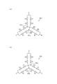
- FIG. 6(a) shows the configuration of the U-phase, V-phase, and W-phase windings in the first stator winding 32a
- Figure 6(b) shows the configuration of the X-phase, Y-phase, and Z-phase windings in the second stator winding 32b.
- the phase windings of each of these stator windings 32a, 32b are connected to each other by a star connection (Y connection).
- the first stator winding 32a has partial windings U1, U2, U3, and U4 as the U-phase winding, partial windings V1, V2, V3, and V4 as the V-phase winding, and partial windings W1, W2, W3, and W4 as the W-phase winding.
- One end of the series-connected partial windings U1 and U2, one end of the series-connected partial windings V1 and V2, and one end of the series-connected partial windings W1 and W2 are connected to each other at a neutral point N1a, and one end of the series-connected partial windings U3 and U4, one end of the series-connected partial windings V3 and V4, and one end of the series-connected partial windings W3 and W4 are connected to each other at a neutral point N1b.
- the second stator winding 32b has partial windings X1, X2, X3, and X4 as the X-phase winding, partial windings Y1, Y2, Y3, and Y4 as the Y-phase winding, and partial windings Z1, Z2, Z3, and Z4 as the Z-phase winding.
- One end of the series-connected body of the partial windings X1 and X2, one end of the series-connected body of the partial windings Y1 and Y2, and one end of the series-connected body of the partial windings Z1 and Z2 are connected to each other at a neutral point N2a, and one end of the series-connected body of the partial windings X3 and X4, one end of the series-connected body of the partial windings Y3 and Y4, and one end of the series-connected body of the partial windings Z3 and Z4 are connected to each other at a neutral point N2b.
- each stator winding 32a, 32b may be configured in such a way that, in addition to being divided into two parts and star-connected as described above, the four partial windings for each phase winding are connected in parallel and then star-connected.
- the neutral points (N1a, N1b) of the first stator winding 32a are combined into one
- the neutral points (N2a, N2b) of the second stator winding 32b are similarly combined into one.
- the partial windings U1 to U4, V1 to V4, and W1 to W4 of each phase may be connected in series, and the three-phase series-connected bodies may be connected by a star connection
- the partial windings X1 to X4, Y1 to Y4, and Z1 to Z4 of each phase may be connected in series, and the three-phase series-connected bodies may be connected by a star connection.
- the total of 18 teeth 34 are grouped into three consecutive teeth 34 in the circumferential direction, and partial windings of two mutually different phases are wound by concentrated winding on each of the three teeth 34 in each group.
- two partial windings of the partial windings U1-U4, V1-V4, and W1-W4 of the first stator winding 32a and two partial windings of the partial windings X1-X4, Y1-Y4, and Z1-Z4 of the second stator winding 32b are wound in a distributed manner on each group of three teeth.
- the partial winding of the first stator winding 32a is wound on one of the teeth 34 on both sides in the circumferential direction
- the partial winding of the second stator winding 32b is wound on the other of each tooth 34.
- the partial windings of both the first and second stator windings 32a, 32b are wound around the central tooth 34 of each tooth group.
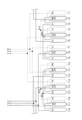
- FIG. 7 is a diagram showing the correspondence between each partial winding of the stator windings 32a, 32b and each of the teeth T1 to T18.
- four partial windings are wound for each tooth group (three consecutive teeth) such as teeth T1 to T3, T4 to T6, T7 to T9, ....
- the partial winding W1 of the second stator winding 32b is wound around the teeth T1.
- the partial winding W2 of the second stator winding 32b and the partial winding X2 of the first stator winding 32a are wound around the teeth T2,
- the partial winding X1 of the first stator winding 32a is wound around the tooth T3.
- each partial winding is wound in a similar manner, and each partial winding is wound around the first to third teeth of each teeth group as shown in the figure.
- Torque ripple is mainly composed of sixth-order electrical harmonic components or twelfth-order electrical harmonic components, so it is desirable to suppress these. Therefore, using the motor 10 configured as described above, it is recommended that the following control be performed in the control device 50.
- the U-phase, V-phase, and W-phase partial windings (first coil bodies) of the first stator winding 32a are wound around the first teeth (T1, T4, T7, T10, T13, and T16) of each tooth group
- a partial winding (second coil body) of one phase of each of the first and second stator windings 32a and 32b is wound around the second teeth (T2, T5, T8, T10, T14, T17) of each tooth group
- the X-phase, Y-phase, and Z-phase partial windings (third coil bodies) of the second stator winding 32b are wound around the third teeth (T3, T6, T9, T12, T15, T18) of each tooth group.
- the control device 50 sets the combined phase difference between the magnetomotive force generated by the partial winding of the first stator winding 32a wound around the second teeth and the magnetomotive force generated by the partial winding of the second stator winding 32b wound around the second teeth so that the phase differences of the magnetomotive force of the second coil body of each phase relative to the magnetomotive force of the first coil body of each phase and the phase differences of the magnetomotive force of the third coil body of each phase relative to the magnetomotive force of the second coil body of each phase are within a predetermined phase range including 20 degrees in electrical angle, or so that the phase differences of the magnetomotive force of the third coil body of each phase relative to the magnetomotive force of the first coil body of each phase and the phase differences of the magnetomotive force of the second coil body of each phase relative to the magnetomotive force of the third coil body of each phase are within a predetermined phase range including 20 degrees in electrical angle.
- the combined phase difference may be set, for example, in the range of 72 to 88 degrees in electrical angle.
- the control device 50 sets the combined phase difference between the current flowing through the partial winding of the first stator winding 32a wound around the second tooth and the current flowing through the partial winding of the second stator winding 32b wound around the second tooth. Details of this control are described in detail in Japanese Patent No. 7103299, filed by the applicant of the present application.
- the motor 10 of this embodiment has a stator 30 with a concentrated winding structure, the rotor 40 has 14 magnetic poles, and the stator 30 has 18 slots. This combination of magnetic poles and slots may cause radial vibrations of the 8th and 10th electrical harmonic components.
- Figure 8(a) is a perspective view showing the stator core structure before the countermeasures in this embodiment are implemented
- Figure 8(b) is a diagram showing the range in which radial acceleration due to the 8th and 10th components occurs in the stator core of Figure 8(a).
- each tooth 34 in the stator core 31 extends parallel to the axial direction, and the flanges provided at the tips of the teeth are equal on both sides in the circumferential direction.
- the radial acceleration shown in Figure 8(b) is based on the results of analysis by the present inventor, and shows that a radially inward acceleration occurs at a position approximately 180° away in the circumferential direction, and a radially outward acceleration occurs at a position approximately 180° away in the circumferential direction and approximately 90° away from the radially inward acceleration, and a radially outward acceleration occurs at a position approximately 90° away from the radially inward acceleration.
- a radial electromagnetic force is generated in the stator core 31 in a direction that causes it to deform into an ellipse, and there is a concern that noise of the same order will be generated.
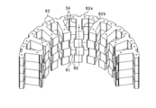
- FIG. 9 is a perspective view showing the step-skew structure of the stator core 31.
- Figure 9 shows a configuration in which the insulating members 63 and 64 have been removed from the configuration of Figure 5 (i.e., an assembly of the core body 62).
- the core body 62 has teeth 34 extending in the radial direction and a yoke portion 62a provided on one radial end of the teeth 34, and a flange portion 62b extending in the circumferential direction is provided at the tip of the teeth 34.
- the yoke portion 62a is a portion that corresponds to the back yoke 33 of the stator core 31 shown in FIG. 2.
- the core body 62 is formed by joining multiple blocks in the axial direction (the vertical direction in the figure).
- the core body 62 is formed by joining four blocks in the axial direction, and the shape of the flange portion 62b at the tip of the teeth is different in each block adjacent to each other in the vertical direction.
- the protruding amount of the flange portion 62b on both sides (left and right sides) in the circumferential direction with respect to the circumferential center position of the tooth 34 is different, and the protruding amount is reversed in each block adjacent to each other in the vertical direction.
- each teeth block B1, B2 has the same shape and is stacked with the axial direction reversed.
- each core body 62 corresponds to a skew portion with step skew.
- the coil winding portion (excluding the flange portion 62b) of each teeth block has the same circumferential center position.
- the number of skew stages in the axial direction of the stator 30 is four, but it is preferable that the number of skew stages in the axial direction be three or more.
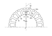
- FIG. 10 is a diagram explaining the skew angle of the stator core 31.
- FIG. 10 is a plan view of the core body 62, showing the first teeth block B1 and the second teeth block B2 overlapping in the axial direction.
- the line connecting the circumferential center position of the teeth and the axis O (center point of the stator) is L
- the circumferential center position of the first teeth block B1 at the tip of the teeth is P1
- the circumferential center position of the second teeth block B2 is P2.
- the angle ⁇ e obtained by adding the angles ⁇ 1 and ⁇ 2 is the skew angle.
- the skew angle ⁇ e is the deviation angle of the circumferential center point of the flange portion 62b.
- FIG. 11 is a diagram showing the relationship between the radial vibration acceleration and the skew angle ⁇ e for the portion of the stator core 31 where the radial vibration acceleration of the 8th and 10th electrical components is at its maximum.
- Figure 11 shows that there is a correlation between the skew angle ⁇ e and the magnitude of the radial vibration acceleration, and that adjusting the skew angle ⁇ e makes it possible to reduce the radial vibration acceleration.
- the radial vibration acceleration is reduced by setting the skew angle ⁇ e in the range of 14 to 23°.
- the stator 30 is skewed to suppress radial vibrations of the eighth and tenth electrical components.
- adding a skew structure reduces the radial electromagnetic force caused by the eighth and tenth electrical components, and suppresses deformation of the stator 30.
- quietness can be improved in a motor 10 with a specific number of magnetic poles and slots.
- the offset angle of the circumferential center point of the flange portion 62b at the tip of the teeth is the skew angle ⁇ e, and the skew angle ⁇ e is set in the range of 14 to 23° in electrical angle. This makes it possible to effectively suppress radial vibrations of the eighth electrical component and the tenth electrical component.
- the desired configuration can be achieved simply by changing the core sheet, which can provide cost benefits.
- the bias direction of the flanges 62b at the teeth tips can be changed, minimizing the increase in cost required to achieve a skewed structure.
- the number of skew stages in the axial direction of the stator 30 is set to three or more, specifically four stages. In this case, the robustness of the radial vibration suppression effect against dimensional variations can be improved compared to, for example, a case in which the number of skew stages is set to two.
- the stator 30 may have a linear skew structure in which the stator 30 is skewed continuously in the axial direction.
- the teeth 34 are arranged to extend in a direction that is inclined with respect to the axial direction, and the center position P11 on one axial end side of the tip of the teeth and the center position P12 on the other axial end side are offset in the circumferential direction.
- the protruding dimension of the flange portion 62b at the tip of the teeth on both sides in the circumferential direction is uniform when viewed in the axial direction, and it is preferable that the protruding dimension is the same on one circumferential side and the other circumferential side, for example.
- the skew angle ⁇ e is the angle between a line connecting the center position P11 at one axial end of the tooth tip and the center point of the stator (not shown) and a line connecting the center position P12 at the other axial end of the tooth tip and the center point of the stator.
- the skew angle ⁇ e is preferably set in the range of 28 to 46° in electrical angle.
- the skew angle ⁇ e corresponds to the circumferential deviation angle caused by linear skew.
- the skew angle ⁇ e is preferably set in the range of 28 to 46° in electrical angle. Even in the case of the above linear skew structure, the radial vibration of the eighth electrical component and the tenth electrical component can be suitably suppressed. Even in the case of a linear skew structure, there is a correlation between the skew angle ⁇ e and the magnitude of the radial vibration acceleration (see FIG. 11), and the radial vibration acceleration can be reduced to a desired level within a specified angle range (electrical angle 28 to 46°).
- the rotor 40 can also be made a skew structure. Specifically, as shown in FIG. 13(a), in the rotor 40, the magnetic pole center positions of the magnetic poles arranged in the circumferential direction are shifted in the axial direction in a stepped manner, and the skew angle ⁇ e, which is the angle of the shift, is preferably set in the range of 14 to 23° in electrical angle.
- a plurality of permanent magnets 42 are fixed to the outer circumferential surface of the rotor core 41, and each magnetic pole is formed by the permanent magnets 42.
- the positions of the permanent magnets 42 arranged in the axial direction are shifted in a stepped manner, resulting in a stepped skew structure.
- the skew angle ⁇ e is the angle formed by a straight line connecting the magnet center position and the rotation center point at one axial end side and a straight line connecting the magnet center position and the rotation center point at the other axial end side.
- the number of axial steps is two, but it is also possible to make it three or more steps (for example, four steps).
- the rotor 40 may have a linear skew structure in which the rotor is skewed continuously in the axial direction.
- the permanent magnets 42 of each magnetic pole are arranged to extend in a direction inclined with respect to the axial direction, and the skew angle ⁇ e, which is the circumferential deviation angle, is preferably set in the range of 28 to 46° in electrical angle.
- the motor 10 it is also possible to use a rotating electric machine in which the number of magnetic poles of the rotor 40 and the number of slots of the stator 30 are determined as follows.
- the number of magnetic poles is set to "22" and the number of slots is set to "18".
- the motor 10 has 16 magnetic poles and 18 slots.
- the number of magnetic poles is set to "20” and the number of slots is set to "18".
- the stator 30 or the rotor 40 is skewed so as to suppress radial vibrations of the eighth electrical component and the tenth electrical component.
- each split core 61 may have multiple teeth 34 in the circumferential direction.
- the split core 61 may have three teeth 34.
- the stator core 31 may also have a structure that does not have a split core structure, that is, a structure that forms an integral ring shape that cannot be divided in the circumferential direction.
- the stator winding 32 has a first stator winding 32a and a second stator winding 32b, and is configured to have a total of six phase windings, but this may be modified so that the stator winding 32 has a three-phase winding.
- the rotating electric machine may be an outer rotor type rotating electric machine instead of an inner rotor type rotating electric machine.
Landscapes
- Engineering & Computer Science (AREA)
- Power Engineering (AREA)
- Iron Core Of Rotating Electric Machines (AREA)
Abstract
Description
周方向に並ぶ複数の磁極を有する回転子と、
周方向に複数のティースを有する固定子コアと、集中巻により前記ティースに巻回される多相の固定子巻線とを有する固定子と、を備える回転電機において、
前記回転子の磁極数が(18±4)であって、かつ前記ティース間のスロット数が18であるか、又は、
前記回転子の磁極数が(18±2)であって、かつ前記ティース間のスロット数が18であり、
電気8次成分及び電気10次成分の径方向振動を抑制するように前記固定子又は前記回転子にスキューが施されている。
・ティースT1には、第2固定子巻線32bの部分巻線W1が巻回され、
・ティースT2には、第2固定子巻線32bの部分巻線W2と第1固定子巻線32aの部分巻線X2とが巻回され、
・ティースT3には、第1固定子巻線32aの部分巻線X1が巻回されている。
その他のティース群については説明を省くが、同様の態様で各部分巻線が巻回されており、各ティース群の第1~第3ティースにおいて図示のごとく各部分巻線が巻回されている。
・各ティース群の第1ティース(T1,T4,T7,T10,T13,T16)に、第1固定子巻線32aにおけるU相、V相、W相の各部分巻線(第1コイル体)が巻回され、
・各ティース群の第2ティース(T2,T5,T8,T10,T14,T17)に、第1,第2固定子巻線32a,32bにおけるいずれか1相ずつの部分巻線(第2コイル体)が巻回され、
・各ティース群の第3ティース(T3,T6,T9,T12,T15,T18)に、第2固定子巻線32bにおけるX相、Y相、Z相の各部分巻線(第3コイル体)が巻回されている。
上記実施形態を例えば次のように変更してもよい。
・モータ10において、磁極数を「22」、スロット数を「18」とする。
・モータ10において、磁極数を「16」、スロット数を「18」とする。
・モータ10において、磁極数を「20」、スロット数を「18」とする。
これら各回転電機においても、上記同様、電気8次成分及び電気10次成分の径方向振動を抑制するように固定子30又は回転子40にスキューが施されているとよい。
Claims (4)
- 周方向に並ぶ複数の磁極を有する回転子(40)と、
周方向に複数のティース(34)を有する固定子コア(31)と、集中巻により前記ティースに巻回される多相の固定子巻線(32)とを有する固定子(30)と、を備える回転電機(10)において、
前記回転子の磁極数が(18±4)であって、かつ前記ティース間のスロット数が18であるか、又は、
前記回転子の磁極数が(18±2)であって、かつ前記ティース間のスロット数が18であり、
電気8次成分及び電気10次成分の径方向振動を抑制するように前記固定子又は前記回転子にスキューが施されている、回転電機。 - 前記固定子又は前記回転子は、軸方向において段差状のスキューが施された段スキュー構造により構成されており、
前記固定子において、前記ティースの先端部に設けられ周方向に延びる鍔部(62b)がスキュー部であり、前記鍔部の周方向中央点のずれ角度であるスキュー角度が、電気角で14~23°の範囲に設定されているか、又は、
前記回転子において、周方向に並ぶ磁極ごとに磁極中心位置が軸方向に段差状にずれており、そのずれ角度であるスキュー角度が、電気角で14~23°の範囲に設定されている、請求項1に記載の回転電機。 - 軸方向に3段以上でスキューが設けられている、請求項2に記載の回転電機。
- 前記固定子又は前記回転子は、軸方向に連続的に傾斜するスキューが施されたリニアスキュー構造により構成されており、
周方向のずれ角度であるスキュー角度が、電気角で28~46°の範囲に設定されている、請求項1に記載の回転電機。
Priority Applications (3)
| Application Number | Priority Date | Filing Date | Title |
|---|---|---|---|
| CN202380080605.3A CN120226232A (zh) | 2022-11-25 | 2023-11-01 | 旋转电机 |
| EP23894385.6A EP4625763A4 (en) | 2022-11-25 | 2023-11-01 | Rotary electric machine |
| US19/214,857 US20250286413A1 (en) | 2022-11-25 | 2025-05-21 | Rotary electric machine |
Applications Claiming Priority (2)
| Application Number | Priority Date | Filing Date | Title |
|---|---|---|---|
| JP2022-188690 | 2022-11-25 | ||
| JP2022188690A JP2024076881A (ja) | 2022-11-25 | 2022-11-25 | 回転電機 |
Related Child Applications (1)
| Application Number | Title | Priority Date | Filing Date |
|---|---|---|---|
| US19/214,857 Continuation US20250286413A1 (en) | 2022-11-25 | 2025-05-21 | Rotary electric machine |
Publications (1)
| Publication Number | Publication Date |
|---|---|
| WO2024111373A1 true WO2024111373A1 (ja) | 2024-05-30 |
Family
ID=91195557
Family Applications (1)
| Application Number | Title | Priority Date | Filing Date |
|---|---|---|---|
| PCT/JP2023/039471 Ceased WO2024111373A1 (ja) | 2022-11-25 | 2023-11-01 | 回転電機 |
Country Status (5)
| Country | Link |
|---|---|
| US (1) | US20250286413A1 (ja) |
| EP (1) | EP4625763A4 (ja) |
| JP (1) | JP2024076881A (ja) |
| CN (1) | CN120226232A (ja) |
| WO (1) | WO2024111373A1 (ja) |
Citations (5)
| Publication number | Priority date | Publication date | Assignee | Title |
|---|---|---|---|---|
| JP2005261122A (ja) * | 2004-03-12 | 2005-09-22 | Nissan Motor Co Ltd | 電動機 |
| JP2009118739A (ja) * | 2002-10-18 | 2009-05-28 | Mitsubishi Electric Corp | 永久磁石式回転電機の製造方法および永久磁石式回転電機 |
| JP2015231261A (ja) * | 2014-06-04 | 2015-12-21 | 三菱電機株式会社 | 三相誘導電動機 |
| JP7103299B2 (ja) | 2019-04-22 | 2022-07-20 | 株式会社デンソー | 回転電機 |
| JP2022188690A (ja) | 2021-06-09 | 2022-12-21 | オリンパス株式会社 | 撮像装置、画像処理装置、画像処理方法、記憶媒体 |
Family Cites Families (3)
| Publication number | Priority date | Publication date | Assignee | Title |
|---|---|---|---|---|
| WO2004093298A1 (ja) * | 2003-04-11 | 2004-10-28 | Mitsubishi Denki Kabushiki Kaisha | 永久磁石式電動機 |
| JP2006149108A (ja) * | 2004-11-22 | 2006-06-08 | Shinko Electric Co Ltd | 永久磁石型モータ |
| DE102010026263A1 (de) * | 2010-07-06 | 2012-01-12 | Daimler Ag | Stator einer elektrischen Maschine |
-
2022
- 2022-11-25 JP JP2022188690A patent/JP2024076881A/ja active Pending
-
2023
- 2023-11-01 WO PCT/JP2023/039471 patent/WO2024111373A1/ja not_active Ceased
- 2023-11-01 CN CN202380080605.3A patent/CN120226232A/zh active Pending
- 2023-11-01 EP EP23894385.6A patent/EP4625763A4/en active Pending
-
2025
- 2025-05-21 US US19/214,857 patent/US20250286413A1/en active Pending
Patent Citations (5)
| Publication number | Priority date | Publication date | Assignee | Title |
|---|---|---|---|---|
| JP2009118739A (ja) * | 2002-10-18 | 2009-05-28 | Mitsubishi Electric Corp | 永久磁石式回転電機の製造方法および永久磁石式回転電機 |
| JP2005261122A (ja) * | 2004-03-12 | 2005-09-22 | Nissan Motor Co Ltd | 電動機 |
| JP2015231261A (ja) * | 2014-06-04 | 2015-12-21 | 三菱電機株式会社 | 三相誘導電動機 |
| JP7103299B2 (ja) | 2019-04-22 | 2022-07-20 | 株式会社デンソー | 回転電機 |
| JP2022188690A (ja) | 2021-06-09 | 2022-12-21 | オリンパス株式会社 | 撮像装置、画像処理装置、画像処理方法、記憶媒体 |
Non-Patent Citations (1)
| Title |
|---|
| See also references of EP4625763A1 |
Also Published As
| Publication number | Publication date |
|---|---|
| EP4625763A4 (en) | 2026-03-04 |
| CN120226232A (zh) | 2025-06-27 |
| US20250286413A1 (en) | 2025-09-11 |
| EP4625763A1 (en) | 2025-10-01 |
| JP2024076881A (ja) | 2024-06-06 |
Similar Documents
| Publication | Publication Date | Title |
|---|---|---|
| US7233089B2 (en) | Permanent magnet rotating electric machine | |
| US20200336058A1 (en) | Rotating electric machine | |
| US20100289370A1 (en) | Synchronous motor having 12 stator teeth and 10 rotor poles | |
| US7569962B2 (en) | Multi-phase brushless motor with reduced number of stator poles | |
| US8390165B2 (en) | Synchronous motor drive system | |
| US10714992B2 (en) | Motor including plurality of rotor parts | |
| WO2011102114A1 (ja) | 同期電動機駆動システム | |
| CN102422510A (zh) | 同步电机 | |
| US20030102727A1 (en) | Permanent magnet type rotary machine | |
| JP5301905B2 (ja) | 複数相回転電機駆動装置、複数相発電機用コンバータ、複数相回転電機、及び回転電機駆動システム | |
| WO2016060232A1 (ja) | ダブルステータ型回転機 | |
| JP5546224B2 (ja) | 磁石式発電機 | |
| WO2019044206A1 (ja) | 回転電機 | |
| JP2014107939A (ja) | ブラシレスモータ | |
| JP2003088078A (ja) | ブラシレスdcモータ | |
| JP5668181B1 (ja) | 磁石式発電機 | |
| WO2024111373A1 (ja) | 回転電機 | |
| WO2024101050A1 (ja) | 固定子 | |
| US10236756B2 (en) | Rotating electric machine | |
| JPH08182280A (ja) | 電動機 | |
| JP6541532B2 (ja) | スイッチドリラクタンスモータ | |
| JP7365956B2 (ja) | ブラシレスモータ及びブラシレスモータ制御方法 | |
| WO2024232250A1 (ja) | 回転電機 | |
| JP2016082775A (ja) | モータ及びモータの駆動方法 | |
| JP2020054063A (ja) | 回転電機 |
Legal Events
| Date | Code | Title | Description |
|---|---|---|---|
| 121 | Ep: the epo has been informed by wipo that ep was designated in this application |
Ref document number: 23894385 Country of ref document: EP Kind code of ref document: A1 |
|
| WWE | Wipo information: entry into national phase |
Ref document number: 202380080605.3 Country of ref document: CN |
|
| WWE | Wipo information: entry into national phase |
Ref document number: 2023894385 Country of ref document: EP |
|
| NENP | Non-entry into the national phase |
Ref country code: DE |
|
| WWP | Wipo information: published in national office |
Ref document number: 202380080605.3 Country of ref document: CN |
|
| ENP | Entry into the national phase |
Ref document number: 2023894385 Country of ref document: EP Effective date: 20250625 |
|
| WWP | Wipo information: published in national office |
Ref document number: 2023894385 Country of ref document: EP |