WO2024116379A1 - 電動車両の制御方法、及び電動車両の制御システム - Google Patents
電動車両の制御方法、及び電動車両の制御システム Download PDFInfo
- Publication number
- WO2024116379A1 WO2024116379A1 PCT/JP2022/044425 JP2022044425W WO2024116379A1 WO 2024116379 A1 WO2024116379 A1 WO 2024116379A1 JP 2022044425 W JP2022044425 W JP 2022044425W WO 2024116379 A1 WO2024116379 A1 WO 2024116379A1
- Authority
- WO
- WIPO (PCT)
- Prior art keywords
- information
- battery
- load
- charging
- upper limit
- Prior art date
- Legal status (The legal status is an assumption and is not a legal conclusion. Google has not performed a legal analysis and makes no representation as to the accuracy of the status listed.)
- Ceased
Links
Images


Classifications
-
- B—PERFORMING OPERATIONS; TRANSPORTING
- B60—VEHICLES IN GENERAL
- B60L—PROPULSION OF ELECTRICALLY-PROPELLED VEHICLES; SUPPLYING ELECTRIC POWER FOR AUXILIARY EQUIPMENT OF ELECTRICALLY-PROPELLED VEHICLES; ELECTRODYNAMIC BRAKE SYSTEMS FOR VEHICLES IN GENERAL; MAGNETIC SUSPENSION OR LEVITATION FOR VEHICLES; MONITORING OPERATING VARIABLES OF ELECTRICALLY-PROPELLED VEHICLES; ELECTRIC SAFETY DEVICES FOR ELECTRICALLY-PROPELLED VEHICLES
- B60L58/00—Methods or circuit arrangements for monitoring or controlling batteries or fuel cells, specially adapted for electric vehicles
- B60L58/10—Methods or circuit arrangements for monitoring or controlling batteries or fuel cells, specially adapted for electric vehicles for monitoring or controlling batteries
- B60L58/24—Methods or circuit arrangements for monitoring or controlling batteries or fuel cells, specially adapted for electric vehicles for monitoring or controlling batteries for controlling the temperature of batteries
- B60L58/25—Methods or circuit arrangements for monitoring or controlling batteries or fuel cells, specially adapted for electric vehicles for monitoring or controlling batteries for controlling the temperature of batteries by controlling the electric load
-
- B—PERFORMING OPERATIONS; TRANSPORTING
- B60—VEHICLES IN GENERAL
- B60L—PROPULSION OF ELECTRICALLY-PROPELLED VEHICLES; SUPPLYING ELECTRIC POWER FOR AUXILIARY EQUIPMENT OF ELECTRICALLY-PROPELLED VEHICLES; ELECTRODYNAMIC BRAKE SYSTEMS FOR VEHICLES IN GENERAL; MAGNETIC SUSPENSION OR LEVITATION FOR VEHICLES; MONITORING OPERATING VARIABLES OF ELECTRICALLY-PROPELLED VEHICLES; ELECTRIC SAFETY DEVICES FOR ELECTRICALLY-PROPELLED VEHICLES
- B60L58/00—Methods or circuit arrangements for monitoring or controlling batteries or fuel cells, specially adapted for electric vehicles
- B60L58/10—Methods or circuit arrangements for monitoring or controlling batteries or fuel cells, specially adapted for electric vehicles for monitoring or controlling batteries
- B60L58/24—Methods or circuit arrangements for monitoring or controlling batteries or fuel cells, specially adapted for electric vehicles for monitoring or controlling batteries for controlling the temperature of batteries
- B60L58/27—Methods or circuit arrangements for monitoring or controlling batteries or fuel cells, specially adapted for electric vehicles for monitoring or controlling batteries for controlling the temperature of batteries by heating
-
- B—PERFORMING OPERATIONS; TRANSPORTING
- B60—VEHICLES IN GENERAL
- B60L—PROPULSION OF ELECTRICALLY-PROPELLED VEHICLES; SUPPLYING ELECTRIC POWER FOR AUXILIARY EQUIPMENT OF ELECTRICALLY-PROPELLED VEHICLES; ELECTRODYNAMIC BRAKE SYSTEMS FOR VEHICLES IN GENERAL; MAGNETIC SUSPENSION OR LEVITATION FOR VEHICLES; MONITORING OPERATING VARIABLES OF ELECTRICALLY-PROPELLED VEHICLES; ELECTRIC SAFETY DEVICES FOR ELECTRICALLY-PROPELLED VEHICLES
- B60L2240/00—Control parameters of input or output; Target parameters
- B60L2240/10—Vehicle control parameters
- B60L2240/12—Speed
-
- B—PERFORMING OPERATIONS; TRANSPORTING
- B60—VEHICLES IN GENERAL
- B60L—PROPULSION OF ELECTRICALLY-PROPELLED VEHICLES; SUPPLYING ELECTRIC POWER FOR AUXILIARY EQUIPMENT OF ELECTRICALLY-PROPELLED VEHICLES; ELECTRODYNAMIC BRAKE SYSTEMS FOR VEHICLES IN GENERAL; MAGNETIC SUSPENSION OR LEVITATION FOR VEHICLES; MONITORING OPERATING VARIABLES OF ELECTRICALLY-PROPELLED VEHICLES; ELECTRIC SAFETY DEVICES FOR ELECTRICALLY-PROPELLED VEHICLES
- B60L2240/00—Control parameters of input or output; Target parameters
- B60L2240/40—Drive Train control parameters
- B60L2240/54—Drive Train control parameters related to batteries
- B60L2240/545—Temperature
-
- B—PERFORMING OPERATIONS; TRANSPORTING
- B60—VEHICLES IN GENERAL
- B60L—PROPULSION OF ELECTRICALLY-PROPELLED VEHICLES; SUPPLYING ELECTRIC POWER FOR AUXILIARY EQUIPMENT OF ELECTRICALLY-PROPELLED VEHICLES; ELECTRODYNAMIC BRAKE SYSTEMS FOR VEHICLES IN GENERAL; MAGNETIC SUSPENSION OR LEVITATION FOR VEHICLES; MONITORING OPERATING VARIABLES OF ELECTRICALLY-PROPELLED VEHICLES; ELECTRIC SAFETY DEVICES FOR ELECTRICALLY-PROPELLED VEHICLES
- B60L2240/00—Control parameters of input or output; Target parameters
- B60L2240/60—Navigation input
- B60L2240/64—Road conditions
- B60L2240/642—Slope of road
-
- B—PERFORMING OPERATIONS; TRANSPORTING
- B60—VEHICLES IN GENERAL
- B60L—PROPULSION OF ELECTRICALLY-PROPELLED VEHICLES; SUPPLYING ELECTRIC POWER FOR AUXILIARY EQUIPMENT OF ELECTRICALLY-PROPELLED VEHICLES; ELECTRODYNAMIC BRAKE SYSTEMS FOR VEHICLES IN GENERAL; MAGNETIC SUSPENSION OR LEVITATION FOR VEHICLES; MONITORING OPERATING VARIABLES OF ELECTRICALLY-PROPELLED VEHICLES; ELECTRIC SAFETY DEVICES FOR ELECTRICALLY-PROPELLED VEHICLES
- B60L2240/00—Control parameters of input or output; Target parameters
- B60L2240/60—Navigation input
- B60L2240/66—Ambient conditions
- B60L2240/662—Temperature
-
- B—PERFORMING OPERATIONS; TRANSPORTING
- B60—VEHICLES IN GENERAL
- B60L—PROPULSION OF ELECTRICALLY-PROPELLED VEHICLES; SUPPLYING ELECTRIC POWER FOR AUXILIARY EQUIPMENT OF ELECTRICALLY-PROPELLED VEHICLES; ELECTRODYNAMIC BRAKE SYSTEMS FOR VEHICLES IN GENERAL; MAGNETIC SUSPENSION OR LEVITATION FOR VEHICLES; MONITORING OPERATING VARIABLES OF ELECTRICALLY-PROPELLED VEHICLES; ELECTRIC SAFETY DEVICES FOR ELECTRICALLY-PROPELLED VEHICLES
- B60L2260/00—Operating Modes
- B60L2260/40—Control modes
- B60L2260/50—Control modes by future state prediction
- B60L2260/54—Energy consumption estimation
-
- B—PERFORMING OPERATIONS; TRANSPORTING
- B60—VEHICLES IN GENERAL
- B60L—PROPULSION OF ELECTRICALLY-PROPELLED VEHICLES; SUPPLYING ELECTRIC POWER FOR AUXILIARY EQUIPMENT OF ELECTRICALLY-PROPELLED VEHICLES; ELECTRODYNAMIC BRAKE SYSTEMS FOR VEHICLES IN GENERAL; MAGNETIC SUSPENSION OR LEVITATION FOR VEHICLES; MONITORING OPERATING VARIABLES OF ELECTRICALLY-PROPELLED VEHICLES; ELECTRIC SAFETY DEVICES FOR ELECTRICALLY-PROPELLED VEHICLES
- B60L2260/00—Operating Modes
- B60L2260/40—Control modes
- B60L2260/50—Control modes by future state prediction
- B60L2260/56—Temperature prediction, e.g. for pre-cooling
-
- B—PERFORMING OPERATIONS; TRANSPORTING
- B60—VEHICLES IN GENERAL
- B60L—PROPULSION OF ELECTRICALLY-PROPELLED VEHICLES; SUPPLYING ELECTRIC POWER FOR AUXILIARY EQUIPMENT OF ELECTRICALLY-PROPELLED VEHICLES; ELECTRODYNAMIC BRAKE SYSTEMS FOR VEHICLES IN GENERAL; MAGNETIC SUSPENSION OR LEVITATION FOR VEHICLES; MONITORING OPERATING VARIABLES OF ELECTRICALLY-PROPELLED VEHICLES; ELECTRIC SAFETY DEVICES FOR ELECTRICALLY-PROPELLED VEHICLES
- B60L58/00—Methods or circuit arrangements for monitoring or controlling batteries or fuel cells, specially adapted for electric vehicles
- B60L58/10—Methods or circuit arrangements for monitoring or controlling batteries or fuel cells, specially adapted for electric vehicles for monitoring or controlling batteries
- B60L58/12—Methods or circuit arrangements for monitoring or controlling batteries or fuel cells, specially adapted for electric vehicles for monitoring or controlling batteries responding to state of charge [SoC]
-
- Y—GENERAL TAGGING OF NEW TECHNOLOGICAL DEVELOPMENTS; GENERAL TAGGING OF CROSS-SECTIONAL TECHNOLOGIES SPANNING OVER SEVERAL SECTIONS OF THE IPC; TECHNICAL SUBJECTS COVERED BY FORMER USPC CROSS-REFERENCE ART COLLECTIONS [XRACs] AND DIGESTS
- Y02—TECHNOLOGIES OR APPLICATIONS FOR MITIGATION OR ADAPTATION AGAINST CLIMATE CHANGE
- Y02T—CLIMATE CHANGE MITIGATION TECHNOLOGIES RELATED TO TRANSPORTATION
- Y02T10/00—Road transport of goods or passengers
- Y02T10/60—Other road transportation technologies with climate change mitigation effect
- Y02T10/70—Energy storage systems for electromobility, e.g. batteries
Definitions
- This invention relates to a control method for an electric vehicle and a control system for an electric vehicle.
- JP2019-160423A discloses a method for determining whether or not a battery installed in a vehicle needs to be charged, and when it is determined that charging is necessary, controlling the temperature of the battery until the charger is connected to the vehicle.
- the battery temperature is likely to rise.
- the battery temperature rises due to charging to the point where output restrictions are triggered, and the vehicle is then rapidly accelerated immediately after this, the battery temperature may rise further, causing output restrictions to be triggered.
- the upper limit temperature of the battery low when it is being charged.
- the charging rate when the battery is fully charged will also be set low. Therefore, when driving at low acceleration or speed after charging the battery, the rise in battery temperature is suppressed, so there is no need to set the upper limit temperature low when the battery is being charged, and the charging rate when the battery is fully charged can also be set accordingly higher.
- the upper limit temperature of the battery during charging and the charging rate of the battery are set lower than necessary, which causes discomfort to the driver.
- the present invention aims to provide a method and system for controlling an electric vehicle that can appropriately set the charging rate of the battery when it is fully charged by controlling the upper limit temperature of the battery based on the vehicle's running state after the battery is charged.
- a method for controlling an electric vehicle that exchanges power between a drive motor and a battery, and limits the charge/discharge power of the battery when the temperature of the battery exceeds a predetermined first upper limit temperature.
- This control method predicts, from information on roads facing a charging point where the battery is charged, which driving mode the vehicle will use to travel from the charging point: low-load driving, in which the vehicle travels with a low load on the battery, or high-load driving, in which the vehicle travels with a high load greater than the low load.
- the upper limit temperature of the battery during charging is set to the first upper limit temperature
- the driving mode is predicted to be low-load driving
- the upper limit temperature of the battery during charging is set to a second upper limit temperature that is higher than the first upper limit temperature and lower than the heat resistance temperature of the battery.
- FIG. 1 is a block diagram illustrating the configuration of a vehicle to which a control system for an electric vehicle according to this embodiment is applied.
- FIG. 2 is a block diagram of a control system for an electric vehicle according to this embodiment.
- FIG. 3 is a diagram showing the relationship between the temperature of the battery and the input/output characteristics of the battery.
- FIG. 4 is a diagram showing the relationship between the charging rate (SOC) of the battery and the input characteristics of the battery.
- FIG. 5 is a flowchart of the control system for the electric vehicle according to this embodiment.
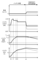
- FIG. 6 is a time chart for a case where the control system for an electric vehicle according to this embodiment predicts that the vehicle will run under high load (rapid acceleration start) after the battery is charged.
- FIG. 7 is a time chart for a case where the control system for an electric vehicle according to this embodiment predicts that the vehicle will run under low load (low acceleration start) after the battery is charged.
- FIG. 1 is a block diagram for explaining the configuration of a vehicle 100 to which the control system for an electric vehicle of this embodiment is applied.
- the vehicle 100 is an electric vehicle.
- An electric vehicle is a vehicle that has a drive motor (hereinafter, simply referred to as a motor 4) as a drive source and runs by generating a drive force due to the torque generated by the motor 4 on one or more wheels.
- electric vehicles include so-called electric automobiles as well as hybrid vehicles that use a motor 4 and an engine as a drive source.
- electric vehicles also include hybrid vehicles that use a motor 4 as a drive source for one of the front and rear wheels and an engine as a drive source for the other wheel.
- a four-wheel drive vehicle refers to a vehicle that uses four wheels as drive wheels 9.
- four-wheel drive vehicles include vehicles that can be switched between two-wheel drive, so-called front-wheel drive or rear-wheel drive, and four-wheel drive.
- a four-wheel drive vehicle can control some of the four wheels as drive wheels 9 in conjunction with each other, and may control the four wheels as drive wheels 9 that drive independently. Therefore, in this embodiment, the electric four-wheel drive vehicle refers to a vehicle 100 that runs by generating driving force due to the torque generated by the motor 4 on some or all of the four wheels.
- the vehicle 100 is an electric four-wheel drive vehicle, but it may also be an electric two-wheel drive vehicle with only the front wheels, or an electric two-wheel drive vehicle with only the rear wheels.
- the vehicle 100 is equipped with a front drive system fds, a rear drive system rds, a battery 1, and a controller 2 (control unit).
- the front drive system fds receives power from the battery 1 and drives the front wheels 9f under the control of the controller 2.
- the front drive system fds includes a front inverter 3f, a front drive motor 4f, a front reduction gear 5f, a front rotation sensor 6f, a front drive shaft 8f, and front wheels 9f.
- the subscript f indicates a front-side configuration.
- the front wheels 9f are a pair of wheels that are relatively forward of the vehicle 100 among the four wheels that the vehicle 100 is equipped with.
- the forward direction of the vehicle 100 is a predetermined direction that is formally determined according to the orientation of the driver's seat, etc.
- the front wheels 9f function as drive wheels 9 that generate the driving force for the vehicle 100 thanks to the front drive system fds.
- the rear drive system rds receives power from the battery 1 and drives the rear wheels 9r under the control of the controller 2.
- the rear drive system rds is symmetrical to the front drive system fds and includes a rear inverter 3r, a rear drive motor 4r, a rear reduction gear 5r, a rear rotation sensor 6r, a rear drive shaft 8r, and rear wheels 9r.
- the subscript r indicates that this is a rear-side configuration.
- the rear wheels 9r are a pair of wheels that are relatively rearward of the vehicle 100 out of the four wheels that the vehicle 100 is equipped with.
- the rearward direction of the vehicle 100 refers to the direction opposite to the forward direction of the vehicle 100. Thanks to the rear drive system rds, the rear wheels 9r function as drive wheels 9 that generate driving force for the vehicle 100.
- Battery 1 is connected to motor 4 via inverter 3, and supplies drive power to motor 4 by discharging. Battery 1 can also be charged by receiving regenerative power from motor 4.
- battery 1 In front drive system fds, battery 1 is connected to front drive motor 4f via front inverter 3f.
- front inverter 3f In front drive system fds, battery 1 is connected to front drive motor 4f via front inverter 3f.
- rear drive system rds battery 1 is connected to rear drive motor 4r via rear inverter 3r.
- the controller 2 is a control device for the vehicle 100, and is a computer that is composed of a central processing unit (CPU), a read-only memory (ROM), a random access memory (RAM), an input/output interface (I/O interface), etc.
- the controller 2 generates control signals for controlling the front drive motor 4f and the rear drive motor 4r based on the vehicle variables of the vehicle 100.
- the vehicle variables are information that indicates the operating state or control state of the entire vehicle 100 or each part that constitutes the vehicle 100, and can be obtained by detection, measurement, calculation, etc.
- the vehicle variables include, for example, the accelerator opening APO, the longitudinal and lateral G, the vehicle speed V, the gradient value, the steering angle, the wheel speed, as well as the rotation speeds Nmf, Nmr of the motors 4f, 4r, the three-phase AC current, etc., which will be described later.
- the controller 2 uses these vehicle variables to control the front drive motor 4f and the rear drive motor 4r, respectively.
- the front inverter 3f and rear inverter 3r convert the DC current supplied from the battery 1 into AC current by turning on/off switching elements in response to a drive signal generated by the controller 2, and adjust the current supplied to the front drive motor 4f and rear drive motor 4r, respectively.
- each inverter 3f, 3r inversely converts the AC current generated by the front drive motor 4f and rear drive motor 4r due to regenerative braking force back into DC current, and adjusts the current supplied to the battery 1.
- the front drive motor 4f and the rear drive motor 4r are, for example, three-phase AC motors, and generate a drive force (torque T) by the AC current supplied from the inverter 3 connected to them.
- the drive force generated by the front drive motor 4f is transmitted to the front wheels 9f via the front reduction gear 5f and the front drive shaft 8f.
- the drive force generated by the rear drive motor 4r is transmitted to the rear wheels 9r via the rear reduction gear 5r and the rear drive shaft 8r.
- the front drive motor 4f and the rear drive motor 4r generate regenerative braking force when rotated by the front wheels 9f and the rear wheels 9r, respectively, and recover the kinetic energy of the vehicle 100 as electrical energy.
- the front drive motor 4f constitutes a drive source (front drive source) that drives the front wheels 9f.
- the rear drive motor 4r constitutes a drive source (rear drive source) that drives the rear wheels 9r independently of the front wheels 9f.
- the front reduction gear 5f and the rear reduction gear 5r are composed of, for example, multiple gears. Each of these reduction gears 5f, 5r generates a driving torque or a braking torque proportional to the reduction ratio by reducing the rotation speed Nm of the motor 4 connected to each of them and transmitting it to the drive shaft 8.
- the front rotation sensor 6f and the rear rotation sensor 6r detect the rotor phase of the motor 4 connected to each of them and output it to the controller 2.
- the controller 2 detects the rotation speed Nmf of the front drive motor 4f based on the output of the front rotation sensor 6f, and detects the rotation speed Nmr of the rear drive motor 4r based on the output of the rear rotation sensor 6r.
- the front current sensor 7f and the rear current sensor 7r detect the current flowing through the motor 4 connected to each of them and output it to the controller 2.
- these current sensors 7f, 7r detect the three-phase AC current of each of the motors 4f, 4r, respectively.
- the vehicle 100 is equipped with various sensors 15 in addition to the front rotation sensor 6f and front current sensor 7f, rear rotation sensor 6r and rear current sensor 7r described above.
- the various sensors 15 include, for example, an accelerator opening sensor 15a, an acceleration sensor 15b, a vehicle speed sensor 15c, as well as a gradient sensor, a steering angle sensor, a wheel speed sensor, and the like.
- the accelerator opening sensor 15a detects the accelerator opening APO, which is the amount of accelerator operation.
- the acceleration sensor 15b detects the acceleration in the longitudinal and lateral directions of the vehicle 100, that is, the longitudinal G and the lateral G.
- the vehicle speed sensor 15c detects the vehicle speed V of the vehicle 100.
- the vehicle speed V is the moving speed of the entire body of the vehicle 100, that is, the vehicle speed.
- the gradient sensor detects the gradient value, which is the gradient of the road on which the vehicle 100 is traveling.
- the steering angle sensor detects the steering angle of the steering wheel.
- the wheel speed sensor detects the wheel speed of each drive wheel 9. The detection values detected by the various sensors 15 are input to the controller 2.
- the target drive torque T_req which is the torque requested by the driver
- the target drive torque T_req which is the torque requested by the driver
- the front torque distribution value RTf which is the torque distribution value RT for the front wheels 9f
- the rear torque distribution value RTr which is the torque distribution value RT for the rear wheels 9r
- the rear torque Tr which is the torque T of the rear drive motor 4r
- the first parameter such as front and rear G
- Fig. 2 is a block diagram of the control system for the electric vehicle of this embodiment.
- Fig. 3 is a diagram showing the relationship between the temperature of the battery 1 and the input/output characteristics of the battery 1.
- Fig. 4 is a diagram showing the relationship between the state of charge (SOC) of the battery 1 and the input characteristics of the battery 1.
- the electric vehicle control system of this embodiment is composed of a navigation device 20, an EV controller 21, a battery controller 22, a charge controller 23, and a charger 24.
- the navigation device 20 generates map information including information on the driving route from the current location (or starting point) of the vehicle 100 to the destination (or intermediate point) and outputs it to the EV controller 21.
- Information on the current location (starting point) of the vehicle 100 is obtained, for example, by a GPS (Global Positioning System) and is obtained by matching it with roads on the map information held by the navigation device 20.
- Destination information is obtained by identifying the destination on the map information through an input operation by the driver.
- the destination is, for example, the end point of navigation, and the position where the entire vehicle system stops.
- Driving route information is obtained by the navigation device 20 selecting a route connecting the current location (starting point) and the destination in the map information.
- the map information includes information on the distance to the destination, information on the positions of the roads that make up the driving route, information on the gradient of the roads, information on the difference in altitude, information on charging points (position, charger output), etc.
- the map information also includes information about roads facing (adjacent to) the charging point, and the road information includes information about attributes (general road, expressway), predicted vehicle speed (legal vehicle speed limit, statistical average vehicle speed), road gradient, etc.
- the charger 24 is located in a service area on a highway, or in a parking lot facing a general road. When the driver inserts the charging plug attached to the charger 24 into a charging socket located on the vehicle 100, the battery 1 can be charged.
- the charging controller 23 is electrically connected to the socket. Therefore, when the charging plug is inserted into the socket, the charging controller 23 detects the charging plug and outputs this as a detection signal to the battery controller 22.
- the charge controller 23 also outputs the allowable charging signal input from the EV controller 21 to the charger 24 as a requested charging signal.
- the allowable charging signal (request charging signal) is a signal for setting the charging power (input) supplied from the charger 24 to the battery 1.
- the charger 24 outputs charging power to the battery 1 based on the requested charging signal input from the charge controller 23.
- the battery controller 22 includes the front inverter 3f and rear inverter 3r, and controls the exchange of power between the battery 1 and the motor 4.
- the battery controller 22 extracts drive power corresponding to the drive signal from the battery 1 and outputs it to the motor 4.
- the battery controller 22 extracts regenerative power corresponding to the regeneration signal from the motor 4 and supplies it to the battery 1.
- the battery controller 22 When a detection signal is input from the charge controller 23, the battery controller 22 outputs information on the temperature of the battery 1 and the charging rate (SOC) of the battery 1 to the EV controller 21.
- the battery controller 22 monitors the temperature of the battery 1.
- a driving mode high load driving
- the battery controller 22 limits the allowable charge/discharge power [kW] of the battery 1 when the temperature of the battery 1 becomes higher than a first upper limit temperature (T max1 , a temperature lower than the heat-resistant temperature) and outputs an allowable charge/discharge signal reflecting the allowable charge/discharge power to the EV controller 21.
- T max1 a temperature lower than the heat-resistant temperature
- the heat-resistant temperature refers to the upper limit temperature at which the battery 1 can operate without receiving irreversible thermal damage.
- the battery controller 22 limits the allowable charge/discharge power [kW] of the battery 1 when the temperature of the battery 1 becomes higher than a second upper limit temperature (T max2 , a temperature lower than the heat resistance temperature) that is higher than the first upper limit temperature, and outputs an allowable charge/discharge signal reflecting the allowable charge/discharge power to the EV controller 21.
- T max2 a second upper limit temperature
- battery controller 22 limits the allowable charging/discharging power of battery 1 and outputs an allowable charging/discharging signal reflecting the allowable charging/discharging power to EV controller 21.
- the magnitude of the allowable charge/discharge power (allowable input/output) between the second upper limit temperature ( Tmax2 ) and the lower limit temperature ( Tmin ) corresponds to the output of the battery 1 during high-load running, which will be described later. Note that, although the input and output characteristics of the battery 1 are the same in Fig. 3, they may have different characteristics.
- the battery controller 22 monitors the state of charge (SOC) of the battery 1, and as shown in FIG. 4 , when the state of charge (SOC) of the battery 1 becomes higher than a predetermined upper limit value (S max : for example, 90%]), it limits the allowable charge/discharge power [kW] of the battery 1 and outputs an allowable charge/discharge signal reflecting the allowable charge/discharge power to the EV controller 21.
- SOC state of charge
- S max for example, 90%
- the EV controller 21 includes the controller 2.
- the EV controller 21 receives map information from the navigation device 20, including information on the driving route from the current location (or starting point) to the destination, predicts the driving mode (low load driving, high load driving) of the vehicle 100 starting from the charging point from the map information, and outputs information on the driving mode to the battery controller 22.
- Low load driving refers to a driving state in which, for example, the acceleration of the vehicle 100 when starting is low, and the speed when traveling at a substantially constant speed is also low (for example, less than 80 km/s).
- the charging point is, for example, in a parking lot facing a general road, and the destination is close to the parking lot (for example, 2-3 km away)
- the driver will only press the accelerator lightly on the general road, meaning that the acceleration and speed will be low and the load on the battery 1 will be low when the vehicle reaches the destination.
- This is predicted as low-load driving. Acceleration appears when the vehicle 100 begins to drive on the general road, but becomes nearly zero when the vehicle speed becomes approximately constant. Therefore, it can be predicted that the initial stage of low-load driving is a low-acceleration start.
- High-load driving refers to a driving state in which, for example, the acceleration of the vehicle 100 when starting off is high, and the speed when traveling at a substantially constant speed is also high (for example, 80 km/s or more).
- the charging point is located, for example, in a service area on a highway, after charging the battery 1, the driver will merge onto the highway, so it is predicted that the driver will increase the amount of pressure on the accelerator and reach high speed driving before merging onto the highway. In this case, the acceleration and speed are high, and the load on the battery 1 is also large. This is predicted as high-load driving. Furthermore, the acceleration remains high at least until the vehicle merges onto the highway. Therefore, it can be predicted that in the initial stage of low-load driving, that is, from the charging point in the service area to the point where the vehicle merges onto the highway, rapid acceleration will occur.
- the accelerator is pressed heavily and a high torque is required from the motor 4.
- the EV controller 21 determines that a high load is required from the battery 1, and predicts high-load driving (high-torque driving) as the driving mode for that road.
- the EV controller 21 estimates low-load driving information (information about low-acceleration starts) and high-load driving information (information about rapid acceleration starts) from map information, and stores this past information.
- the EV controller 21 therefore determines whether there is past information (map information containing the same information) for the current map information (such as information on predicted vehicle speeds on roads leading to a charging point) input from the navigation device 20, and if past information is available, it may extract information on low-load driving (information on low-acceleration starts) and information on high-load driving (information on rapid acceleration starts) associated with the past information, and execute the control described below. This reduces the processing load on the EV controller 21.
- the EV controller 21 may be configured to compare the current map information with past map information that has common predicted vehicle speed information for roads leading to charging points, compare the amount of information on low-load driving (low acceleration start) and the amount of information on high-load driving (rapid acceleration start) contained in the past map information, and set the driving mode based on the amount of information. This enables control that reflects the driver's driving style.
- the driving route from the current location (or starting point) of the vehicle 100 to the destination has a monotonous terrain, and that the load (input/output) on the battery 1 is approximately constant.
- the EV controller 21 it is also preferable for the EV controller 21 to predict either low-load driving (low acceleration start) or high-load driving (rapid acceleration start) as the driving mode based on the average load on the battery 1 from the starting point to the charging point. This can reduce the processing burden on the EV controller 21.
- the EV controller 21 generates an allowable charging signal based on information about the temperature of the battery 1 and the charging rate (SOC) of the battery 1, and outputs it to the charging controller 43.
- the EV controller 21 predicts that the driving mode will be high-load driving (high acceleration start) when charging the battery 1 of the vehicle 100, it sets an upper limit value of the allowable charging power related to the allowable charging signal based on the allowable charging/discharging signal (a signal that limits the allowable charging/discharging power above the first upper limit temperature (T max1 )) input from the battery controller 22.
- the EV controller 21 when the EV controller 21 predicts that the driving mode will be low-load driving (low acceleration start) when charging the battery 1 of the vehicle 100, it sets an upper limit value of the allowable charging power related to the allowable charging signal based on the allowable charging/discharging signal input from the battery controller 22 (a signal that limits the allowable charging/discharging power above the second upper limit temperature (T max2 )).
- FIG. 5 is a flowchart of the control system for the electric vehicle according to this embodiment.
- the vehicle 100 arrives at the charging point, the charging plug of the charger 24 is inserted into the charging socket of the vehicle 100, and the battery controller 22 receives a detection signal and transmits information about the temperature of the battery 1 and the charging state (SOC) of the battery 1 to the EV controller 21.
- SOC charging state
- step S101 the EV controller 21 outputs an allowable charging signal to the charging controller 23.
- This causes the charging controller 23 to output a required power generation signal to the charger 24, and the charger 24 supplies charging power to the battery 1 based on the required charging signal (allowable charging signal), thereby starting charging of the battery 1.
- step S102 the EV controller 21 predicts the driving mode that the vehicle 100 will use when traveling from the charging point based on map information from the navigation device 20, including information on the road facing the charging point (estimated vehicle speed information, gradient information).
- step S103 the EV controller 21 determines whether the driving mode is low-load driving (low acceleration start). If the answer is YES, the process proceeds to step S104. If the answer is NO, the process proceeds to step S112, assuming that the driving mode is high-load driving (rapid acceleration start).
- step S104 the EV controller 21 sets the upper limit temperature during charging of the battery 1 to a second upper limit temperature (T max2 ).
- step S105 the EV controller 21 determines whether the charging rate of the battery 1 has reached a predetermined value (e.g., 50% or not), and if the result is YES, the process proceeds to step S106, and if the result is NO, the process proceeds to step S107.
- a predetermined value e.g. 50% or not
- step S106 the EV controller 21 (battery controller 22) limits the input (charging power) to the battery 1 according to the map in Figure 4.
- step S107 the EV controller 21 determines whether the temperature of the battery 1 has reached a second upper limit temperature (T max2 ), and if YES, the process proceeds to step S108, and if NO, the process proceeds to step S109.
- T max2 a second upper limit temperature
- step S108 the EV controller 21 limits the input (charging power) of the battery 1 according to the map in FIG. 3. If the input (charging power) of the battery 1 is limited in step S106 (or step S113), the input (charging power) of the battery 1 is further limited in step S108.
- step S109 it is determined whether or not the battery 1 has reached full charge. If the answer is YES, the process proceeds to step S110. If the answer is NO, the process remains in step S109.
- full charge refers to the state in which the charging rate of the battery 1 reaches a predetermined upper limit (e.g., 90%) or a predetermined time has elapsed since the start of charging.
- step S110 the EV controller 21 stops input (charging) to the battery 1.
- step S111 the EV controller 21 sets the upper limit temperature during charging of the battery 1 to a first upper limit temperature (T max1 ).
- step S112 the EV controller 21 determines whether the charging rate of the battery 1 has reached a predetermined value (e.g., 50% or not), and if YES, proceeds to step S113, and if NO, proceeds to step S114.
- a predetermined value e.g. 50% or not
- step S113 the EV controller 21 (battery controller 22) limits the input (charging power) to the battery 1 according to the map in Figure 4.
- step S114 the EV controller 21 determines whether the temperature of the battery 1 has reached a first upper limit temperature (T max1 ), and if YES, the process proceeds to step S108, and if NO, the process proceeds to step S109.
- T max1 a first upper limit temperature
- Fig. 6 is a time chart for the case where the control system for an electric vehicle of this embodiment predicts that the vehicle 100 will run under high load (rapid acceleration start) after charging the battery 1.
- Fig. 6 shows a comparison between a time chart (solid line) for the case where the upper limit temperature of the battery 1 during charging is set to a first upper limit temperature ( Tmax1 ) (step S111 in Fig. 5) and a time chart (dashed line) for the case where the upper limit temperature of the battery 1 during charging is set to a second upper limit temperature ( Tmax2 ).
- the EV controller 21 (battery controller 22) starts charging the battery 1 at time t0, the input (charging power) to the battery 1, the temperature of the battery 1, and the charging state (SOC) of the battery 1 increase.
- the EV controller 21 predicts that the driving mode of the vehicle 100 will be high-load driving (rapid acceleration start) after charging the battery 1, based on information about the roads facing the charging point, etc.
- the upper limit temperature of the battery 1 during charging is set to the first upper limit temperature ( Tmin1 )
- the temperature of the battery 1 reaches the first upper limit temperature ( Tmax1 ) at time t2
- the input (charging power) of the battery 1 is limited based on the map (solid line) shown in Fig. 3.
- the input (solid line) of the battery 1 further decreases after time t1, and the rate of increase (slope) of the charging rate of the battery 1 (solid line) also further decreases.
- the battery 1 reaches a full charge state, completing the charging of the battery 1, and the vehicle 100 runs under high load (rapid acceleration start).
- the temperature of the battery 1 is at a first upper limit temperature ( Tmax1 ) that is lower than a second upper limit temperature ( Tmax2 ), so the input/output of the battery 1 is not limited by the temperature, and the battery 1 can provide the output (solid line) and vehicle speed (solid line) required by the driver.
- the input of battery 1 is not restricted at time t2 , and when the temperature of battery 1 reaches the second upper limit temperature ( Tmax2 ) at time t3 after time t2, the input (charging power) of battery 1 is restricted based on the map (dashed line) shown in Fig. 3. As a result, the input of battery 1 (dashed line) decreases after time t3, and the rate of increase (slope) of the charging rate of battery 1 (dashed line) also decreases.
- FIG. 7 is a time chart for a case where the control system for an electric vehicle according to this embodiment predicts that the vehicle 100 will run at a low load (low acceleration start) after the battery 1 is charged.
- Figure 7 shows a case in which it is predicted that the vehicle 100 will be driven at low load (low acceleration start) after charging, and compares a time chart (solid line) when the upper limit temperature of the battery 1 during charging is set to the second upper limit temperature ( Tmax2 ) (step S104 in Figure 5) with a time chart (dashed line) when the upper limit temperature of the battery 1 during charging is set to the first upper limit temperature ( Tmax1 ).
- the EV controller 21 (battery controller 22) starts charging the battery 1 at time t0, the input to the battery 1, the temperature of the battery 1, and the state of charge (SOC) of the battery 1 increase.
- the EV controller 21 predicts that the driving mode of the vehicle 100 will be low-load driving (low acceleration start) after charging the battery 1, based on information about the roads facing the charging point, etc.
- the upper limit temperature of battery 1 during charging is set to the first upper limit temperature ( Tmax1 )
- the input (charging power) of battery 1 is limited based on the map (solid line) shown in Fig. 3.
- the input (dashed line) of battery 1 further decreases after time t2, and the rate of increase (slope) of the charging rate of battery 1 (dashed line) also further decreases.
- the SOC of battery 1 reaches the charging rate at full charge, completing the charging of battery 1, and vehicle 100 runs under low load (low acceleration start).
- the temperature of battery 1 does not increase thereafter and decreases monotonically.
- the upper limit temperature of battery 1 during charging is set to the second upper limit temperature ( Tmax2 )
- the input (charging power) of battery 1 is limited based on the map (dashed line) in Fig. 3.
- the input (solid line) of battery 1 further decreases after time t3, and the rate of increase (slope) of the charging rate of battery 1 (solid line) also further decreases.
- the upper limit temperature of the battery 1 during charging is set to the first upper limit temperature ( Tmax1 )
- the upper limit temperature of the battery 1 during charging is set to a second upper limit temperature ( Tmax2 ) that is higher than the first upper limit temperature ( Tmax1 ) and lower than the heat resistance temperature of the battery 1.
- the upper limit temperature during charging of the battery 1 is set to the first upper limit temperature ( Tmax1 ), so that the battery 1 can provide the output expected by the driver after charging. Also, when the driving mode after charging of the battery 1 is low-load driving, the upper limit temperature during charging of the battery 1 is set to the second upper limit temperature ( Tmax2 ), so that the state of charge (SOC) of the battery 1 expected by the driver after charging can be obtained.
- information on low-load driving, high-load driving, and charging point information are estimated from map information representing roads.
- the above method makes it possible to easily estimate information on low-load driving, high-load driving, and charging points from map information.
- charging point information is estimated from map information showing roads, and past low-load driving information or high-load driving information calculated using past map information in which the map information and charging point information are the same is set as the driving mode.
- the above method allows for easy and highly accurate estimation of charging points, and also allows for the extraction of low-load or high-load driving information from past information to set the driving mode, reducing the processing burden (on the EV controller 21).
- information on low-load driving and information on high-load driving are estimated based on the load from the departure point of the vehicle 100 to the charging point.
- charging point information is estimated from map information showing roads, and the map information includes information on predicted vehicle speeds on roads facing the charging point.
- Past map information with common predicted vehicle speed information for roads is extracted, and the amount of information on low-load driving and the amount of information on high-load driving contained in the past map information are compared, and the driving mode is set based on the amount of information.
- the above method allows the driver to set the driving mode to suit their driving style.
- charging point information is estimated from map information representing roads, and the map information includes information on predicted vehicle speeds on the roads. If the predicted vehicle speed on the road is equal to or greater than a predetermined speed, high-load driving is predicted as the driving mode.
- the above method makes it possible to predict high-load driving as a driving mode with high accuracy from map information.
- charging point information is estimated from map information representing roads, and the map information includes information on the gradient of the road facing the charging point. If the road facing the charging point in the map information has a predetermined upward gradient and continues for a predetermined distance, high-load driving is predicted as the driving mode.
- the above method makes it possible to predict high-load driving as a driving mode with high accuracy from map information.
- the low-load driving information when vehicle 100 accelerates in a short time after departing from a charging point and travels at an approximately constant speed, the low-load driving information includes low-acceleration start information indicating that vehicle 100 traveled from the charging point at a low speed when the vehicle started traveling, and the high-load driving information includes sudden acceleration start information indicating that vehicle 100 traveled from the charging point with sudden acceleration when the vehicle started traveling, and either low-acceleration start or sudden acceleration start is selected as the driving mode, and when the driving mode is predicted to be sudden acceleration start, the upper limit temperature of battery 1 when charging battery 1 is set to a first upper limit temperature ( Tmax1 ), and when the driving mode is predicted to be low-acceleration start, the upper limit temperature of battery 1 when charging battery 1 is set to a second upper limit temperature ( Tmax2 ).
- Tmax1 first upper limit temperature
- Tmax2 second upper limit temperature
- the upper limit temperature during charging of the battery 1 is set to the first upper limit temperature ( Tmax1 ), so that the battery 1 can provide the output expected by the driver after charging. Also, when the driving mode after charging of the battery 1 is low acceleration start, the upper limit temperature during charging of the battery 1 is set to the second upper limit temperature ( Tmax2 ), so that the charging rate of the battery 1 when fully charged expected by the driver can be obtained.
- charging point information is estimated from map information showing roads, and past low acceleration start information or rapid acceleration start information calculated using past map information in which the map information and charging point information are the same is set as the driving mode.
- the above method allows the charging point to be estimated easily and with high accuracy, and also extracts information on low acceleration starts or rapid acceleration starts from past information and sets the driving mode, thereby reducing the processing load (on the EV controller 21).
- information on low acceleration start and information on rapid acceleration start are estimated based on the load from the starting point of the vehicle 100 to the charging point.
- charging point information is estimated from map information showing roads, and the map information includes information on the predicted vehicle speed of the road facing the charging point.
- Past map information with common predicted vehicle speed information for the road is extracted, and the number of pieces of information on low acceleration starts and the number of pieces of information on rapid acceleration starts contained in the past map information are compared, and the driving mode is set based on the number of pieces of information.
- the above method allows the driver to set the driving mode to suit their driving style.
- charging point information is estimated from map information showing roads, and the map information includes information on predicted vehicle speeds on the roads. If the predicted vehicle speed in the map information is equal to or greater than a predetermined speed, rapid acceleration start is predicted as the driving mode.
- the above method makes it possible to predict sudden acceleration starts as a driving mode with high accuracy from map information.
- the control system for an electric vehicle includes a drive motor (motor 4), a battery 1 that exchanges power between the drive motor (motor 4), and a control unit (EV controller 21) that limits the charge/discharge power (input/output) of the battery 1 when the temperature of the battery 1 exceeds a predetermined first upper limit temperature ( Tmax1 ).
- the control unit (EV controller 21) predicts, from information about roads facing a charging point where the battery 1 is charged, which driving mode the vehicle 100 will use to run from the charging point: low-load driving, in which the vehicle 100 runs with the load on the battery 1 being low, or high-load driving, in which the vehicle 100 runs with the load on the battery 1 being higher than the low load, and when the driving mode is predicted to be high-load driving, sets the upper limit temperature of the battery 1 when charging the battery 1 to the first upper limit temperature ( Tmax1 ), and when the driving mode is predicted to be low-load driving, sets the upper limit temperature of the battery 1 when charging the battery 1 to the first upper limit temperature ( Tmax1 ). ) and lower than the heat resistance temperature of the battery 1.
- the upper limit temperature during charging of the battery 1 is set to the first upper limit temperature ( Tmax1 ), so that the battery 1 can provide the output expected by the driver after charging.
- the upper limit temperature during charging of the battery 1 is set to the second upper limit temperature ( Tmax2 ), so that the charging rate of the battery 1 when fully charged expected by the driver can be obtained.
Landscapes
- Engineering & Computer Science (AREA)
- Life Sciences & Earth Sciences (AREA)
- Sustainable Development (AREA)
- Sustainable Energy (AREA)
- Power Engineering (AREA)
- Transportation (AREA)
- Mechanical Engineering (AREA)
- Electric Propulsion And Braking For Vehicles (AREA)
Abstract
Description
図1は、本実施形態の電動車両の制御システムが適用される車両100の構成を説明するブロック図である。車両100は電動車両である。電動車両とは駆動源として駆動モータ(以下、単にモータ4という)を備え、1又は複数の車輪にモータ4が発生するトルクに起因した駆動力を発生させることによって走行する車両をいう。このため、電動車両にはいわゆる電気自動車の他、駆動源としてモータ4とエンジンを併用するハイブリッド車両を含まれる。例えば、電動車両には、前輪と後輪のいずれか一方の車輪の駆動源としてモータ4を使用し、他方の車輪の駆動源としてエンジンを使用するハイブリッド車両も含む。また、四輪駆動車両とは4つの車輪を駆動輪9として利用する車両をいう。四輪駆動車両は常に4個の車輪を駆動輪9として利用する車両の他、いわゆる前輪駆動又は後輪駆動の二輪駆動と四輪駆動とで切り替えが可能な車両を含む。また、四輪駆動車両は4個の車輪の一部を連動して駆動輪9として制御でき、4個の車輪を独立して駆動する駆動輪9として制御する場合がある。従って、本実施形態で電動四輪駆動車両とは、4つの車輪のうち一部又は全部の車輪に、モータ4が発生するトルクに起因した駆動力を発生させることによって走行する車両100をいう。
図2は、本実施形態の電動車両の制御システムのブロック図である。図3は、バッテリ1の温度とバッテリ1の入出力特性との関係を示す図である。図4は、バッテリ1の充電率(SOC)とバッテリ1の入力特性との関係を示す図である。
図5は、本実施形態の電動車両の制御システムのフローチャートである。
図6は、本実施形態の電動車両の制御システムにおいてバッテリ1の充電後に車両100が高負荷走行(急加速発進)で走行すると予測した場合のタイムチャートである。図6は、充電後に車両100が高負荷走行(急加速発進)で走行すると予測する場合であって、充電中のバッテリ1の上限温度を第1上限温度(Tmax1)に設定(図5のステップS111)したときのタイムチャート(実線)と、充電中のバッテリ1の上限温度を第2上限温度(Tmax2)に設定したときのタイムチャート(破線)を比較している。
図7は、本実施形態の電動車両の制御システムにおいてバッテリ1の充電後に車両100が低負荷走行(低加速発進)で走行すると予測した場合のタイムチャートである。
本実施形態の電動車両の制御方法によれば、駆動モータ(モータ4)とバッテリ1との間で電力の授受を行うとともに、車両100の走行中のバッテリ1の温度が所定の第1上限温度(Tmax1)を超える場合にバッテリ1の充放電電力を制限する電動車両の制御方法であって、バッテリ1の充電を行う充電ポイントに面した道路の情報から、バッテリ1に対する負荷が低負荷の状態で車両100が走行する低負荷走行、又は負荷が低負荷よりも大きな高負荷の状態で車両100が走行する高負荷走行のいずれの走行モードにより車両100が充電ポイントから走行するかを予測し、走行モードが高負荷走行と予測される場合に、バッテリ1の充電時のバッテリ1の上限温度を第1上限温度(Tmax1)に設定し、走行モードが低負荷走行と予測される場合に、バッテリ1の充電時のバッテリ1の上限温度を第1上限温度(Tmax1)よりも高い温度であってバッテリ1の耐熱温度よりも低い第2上限温度(Tmax2)に設定する。
Claims (13)
- 駆動モータとバッテリとの間で電力の授受を行うとともに、前記バッテリの温度が所定の第1上限温度を超える場合に前記バッテリの充放電電力を制限する電動車両の制御方法であって、
前記バッテリの充電を行う充電ポイントに面した道路の情報から、前記バッテリに対する負荷が低負荷の状態で車両が走行する低負荷走行、又は前記負荷が前記低負荷よりも大きな高負荷の状態で前記車両が走行する高負荷走行のいずれの走行モードにより前記車両が前記充電ポイントから走行するかを予測し、
前記走行モードが前記高負荷走行と予測される場合に、前記バッテリの充電時の前記バッテリの上限温度を前記第1上限温度に設定し、
前記走行モードが前記低負荷走行と予測される場合に、前記バッテリの充電時の前記バッテリの上限温度を前記第1上限温度よりも高い温度であって前記バッテリの耐熱温度よりも低い第2上限温度に設定する電動車両の制御方法。 - 前記低負荷走行の情報、前記高負荷走行の情報、及び前記充電ポイントの情報を、前記道路を表す地図情報から推定する請求項1に記載の電動車両の制御方法。
- 前記充電ポイントの情報を、前記道路を表す地図情報から推定し、
前記地図情報と前記充電ポイントの情報が同一の過去の前記地図情報を用いて算出された過去の前記低負荷走行の情報又は前記高負荷走行の情報を前記走行モードに設定する請求項1に記載の電動車両の制御方法。 - 前記低負荷走行の情報及び前記高負荷走行の情報を、前記車両の出発地から前記充電ポイントまでの前記負荷に基づいて推定する請求項1に記載の電動車両の制御方法。
- 前記充電ポイントの情報を、前記道路を表す地図情報から推定し、
前記地図情報は、前記充電ポイントに面した前記道路の予測車速の情報を含み、
前記道路の前記予測車速の情報が共通する過去の前記地図情報を抽出し、過去の前記地図情報に含まれる前記低負荷走行の情報数と前記高負荷走行の情報数を比較し、情報数の多い方を前記走行モードに設定する請求項1に記載の電動車両の制御方法。 - 前記充電ポイントの情報を、前記道路を表す地図情報から推定し、
前記地図情報は、前記道路の予測車速の情報を含み、
前記道路の前記予測車速が所定の速度以上となる場合、前記走行モードとして前記高負荷走行を予測する請求項1に記載の電動車両の制御方法。 - 前記充電ポイントの情報を、前記道路を表す地図情報から推定し、
前記地図情報は、前記充電ポイントに面する前記道路の勾配の情報を含み、
前記地図情報において、前記充電ポイントに面する前記道路が所定の上りの勾配を有し且つ前記道路が所定距離続く場合、前記走行モードとして前記高負荷走行を予測する請求項1に記載の電動車両の制御方法。 - 前記車両が前記充電ポイントから出発後短時間で加速し略等速で走行する場合において、
前記低負荷走行の情報は、前記充電ポイントから前記車両が走行開始時に低速度で発進したことを表す低加速発進の情報を含み、
前記高負荷走行の情報は、前記充電ポイントから前記車両が走行開始時に急加速で発進したことを表す急加速発進の情報を含み、
前記走行モードとして、前記低加速発進又は前記急加速発進のいずれかが選択されるものとし、
前記走行モードが前記急加速発進と予測される場合に、前記バッテリの充電時の前記バッテリの上限温度を前記第1上限温度に設定し、
前記走行モードが前記低加速発進と予測される場合に、前記バッテリの充電時の前記バッテリの上限温度を前記第2上限温度に設定する請求項1に記載の電動車両の制御方法。 - 前記充電ポイントの情報を、前記道路を表す地図情報から推定し、
前記地図情報と前記充電ポイントの情報が同一の過去の前記地図情報を用いて算出された過去の前記低加速発進の情報又は前記急加速発進の情報を前記走行モードに設定する請求項8に記載の電動車両の制御方法。 - 前記低加速発進の情報及び前記急加速発進の情報を、前記車両の出発地から前記充電ポイントまでの前記負荷に基づいて推定する請求項8に記載の電動車両の制御方法。
- 前記充電ポイントの情報を、前記道路を表す地図情報から推定し、
前記地図情報は、前記充電ポイントに面した前記道路の予測車速の情報を含み、
前記道路の前記予測車速の情報が共通する過去の前記地図情報を抽出し、過去の前記地図情報に含まれる前記低加速発進の情報数と前記急加速発進の情報数を比較し、情報数の多い方を前記走行モードに設定する請求項8に記載の電動車両の制御方法。 - 前記充電ポイントの情報を、前記道路を表す地図情報から推定し、
前記地図情報は、前記道路の予測車速の情報を含み、
前記地図情報において、前記予測車速が所定の速度以上となる場合、前記走行モードとして前記急加速発進を予測する請求項8に記載の電動車両の制御方法。 - 駆動モータと、
前記駆動モータとの間で電力の授受を行うバッテリと、
前記バッテリの温度が所定の第1上限温度を超える場合に前記バッテリの充放電電力を制限する制御部と、を含む電動車両の制御システムであって、
前記制御部は、
前記バッテリの充電を行う充電ポイントに面した道路の情報から、前記バッテリに対する負荷が低負荷の状態で車両が走行する低負荷走行、又は前記負荷が前記低負荷よりも大きな高負荷の状態で前記車両が走行する高負荷走行のいずれの走行モードにより前記車両が前記充電ポイントから走行するかを予測し、
前記走行モードが前記高負荷走行と予測される場合に、前記バッテリの充電時の前記バッテリの上限温度を前記第1上限温度に設定し、
前記走行モードが前記低負荷走行と予測される場合に、前記バッテリの充電時に前記バッテリの上限温度を前記第1上限温度よりも高い温度であって前記バッテリの耐熱温度よりも低い第2上限温度に設定する電動車両の制御システム。
Priority Applications (4)
| Application Number | Priority Date | Filing Date | Title |
|---|---|---|---|
| CN202280102082.3A CN120265499A (zh) | 2022-12-01 | 2022-12-01 | 电动车辆的控制方法以及电动车辆的控制系统 |
| PCT/JP2022/044425 WO2024116379A1 (ja) | 2022-12-01 | 2022-12-01 | 電動車両の制御方法、及び電動車両の制御システム |
| EP22967211.8A EP4628354A4 (en) | 2022-12-01 | 2022-12-01 | METHOD FOR CONTROLLING AN ELECTRIC VEHICLE AND CONTROL SYSTEM FOR AN ELECTRIC VEHICLE |
| JP2024561104A JPWO2024116379A1 (ja) | 2022-12-01 | 2022-12-01 |
Applications Claiming Priority (1)
| Application Number | Priority Date | Filing Date | Title |
|---|---|---|---|
| PCT/JP2022/044425 WO2024116379A1 (ja) | 2022-12-01 | 2022-12-01 | 電動車両の制御方法、及び電動車両の制御システム |
Publications (1)
| Publication Number | Publication Date |
|---|---|
| WO2024116379A1 true WO2024116379A1 (ja) | 2024-06-06 |
Family
ID=91323404
Family Applications (1)
| Application Number | Title | Priority Date | Filing Date |
|---|---|---|---|
| PCT/JP2022/044425 Ceased WO2024116379A1 (ja) | 2022-12-01 | 2022-12-01 | 電動車両の制御方法、及び電動車両の制御システム |
Country Status (4)
| Country | Link |
|---|---|
| EP (1) | EP4628354A4 (ja) |
| JP (1) | JPWO2024116379A1 (ja) |
| CN (1) | CN120265499A (ja) |
| WO (1) | WO2024116379A1 (ja) |
Citations (5)
| Publication number | Priority date | Publication date | Assignee | Title |
|---|---|---|---|---|
| JP2019160423A (ja) | 2018-03-07 | 2019-09-19 | 株式会社デンソー | 電池温度制御装置 |
| JP2021027797A (ja) * | 2019-08-07 | 2021-02-22 | 株式会社デンソー | バッテリ管理装置、バッテリ管理方法及びバッテリ管理プログラム |
| US20210229570A1 (en) * | 2018-06-19 | 2021-07-29 | Einride Ab | Predictive remote thermal managment |
| JP2022040626A (ja) * | 2020-08-31 | 2022-03-11 | いすゞ自動車株式会社 | 充電制御装置 |
| JP2022123628A (ja) * | 2021-02-12 | 2022-08-24 | いすゞ自動車株式会社 | 温度調節装置 |
Family Cites Families (6)
| Publication number | Priority date | Publication date | Assignee | Title |
|---|---|---|---|---|
| JP3687429B2 (ja) * | 1999-08-05 | 2005-08-24 | 日産自動車株式会社 | 車両用制動力制御装置 |
| JP2011063186A (ja) * | 2009-09-18 | 2011-03-31 | Denso Corp | 車両駆動制御装置 |
| JP2013060034A (ja) * | 2011-09-12 | 2013-04-04 | Toyota Motor Corp | 車両および車両の制御方法 |
| US10464547B2 (en) * | 2017-07-13 | 2019-11-05 | GM Global Technology Operations LLC | Vehicle with model-based route energy prediction, correction, and optimization |
| US10800287B2 (en) * | 2018-08-17 | 2020-10-13 | GM Global Technology Operations LLC | Vehicle rechargeable energy storage system and method of preconditioning the rechargeable energy storage system |
| WO2021024732A1 (ja) * | 2019-08-07 | 2021-02-11 | 株式会社デンソー | バッテリ管理装置、バッテリ管理方法及びバッテリ管理プログラム |
-
2022
- 2022-12-01 EP EP22967211.8A patent/EP4628354A4/en active Pending
- 2022-12-01 CN CN202280102082.3A patent/CN120265499A/zh active Pending
- 2022-12-01 WO PCT/JP2022/044425 patent/WO2024116379A1/ja not_active Ceased
- 2022-12-01 JP JP2024561104A patent/JPWO2024116379A1/ja active Pending
Patent Citations (5)
| Publication number | Priority date | Publication date | Assignee | Title |
|---|---|---|---|---|
| JP2019160423A (ja) | 2018-03-07 | 2019-09-19 | 株式会社デンソー | 電池温度制御装置 |
| US20210229570A1 (en) * | 2018-06-19 | 2021-07-29 | Einride Ab | Predictive remote thermal managment |
| JP2021027797A (ja) * | 2019-08-07 | 2021-02-22 | 株式会社デンソー | バッテリ管理装置、バッテリ管理方法及びバッテリ管理プログラム |
| JP2022040626A (ja) * | 2020-08-31 | 2022-03-11 | いすゞ自動車株式会社 | 充電制御装置 |
| JP2022123628A (ja) * | 2021-02-12 | 2022-08-24 | いすゞ自動車株式会社 | 温度調節装置 |
Non-Patent Citations (1)
| Title |
|---|
| See also references of EP4628354A1 |
Also Published As
| Publication number | Publication date |
|---|---|
| JPWO2024116379A1 (ja) | 2024-06-06 |
| EP4628354A4 (en) | 2026-01-07 |
| EP4628354A1 (en) | 2025-10-08 |
| CN120265499A (zh) | 2025-07-04 |
Similar Documents
| Publication | Publication Date | Title |
|---|---|---|
| US6930405B2 (en) | Vehicle control apparatus | |
| JP3613216B2 (ja) | ハイブリッド車両の制御装置 | |
| KR102371248B1 (ko) | E-4wd 하이브리드 차량의 제어 방법 | |
| CN101489824B (zh) | 车辆的电力控制装置 | |
| JP7549502B2 (ja) | 電動車両のバッテリ管理システム、及び、電動車両 | |
| JP3614341B2 (ja) | ハイブリッド電気自動車の表示装置 | |
| JP2001238304A (ja) | ハイブリッド電気自動車の発電制御装置 | |
| JP7657082B2 (ja) | 車両制御装置、車両制御方法、およびプログラム | |
| WO2013051104A1 (ja) | 充電制御装置および充電制御方法 | |
| JP2000175306A (ja) | ハイブリッド車両の制御装置 | |
| JP2000175364A (ja) | ハイブリッド車両の制御装置 | |
| KR20170011162A (ko) | 구동 모터를 구비한 차량의 dc 컨버터의 출력 전압을 제어하는 방법 및 장치 | |
| KR100901591B1 (ko) | 전기자동차용 회생제동 제어 방법 | |
| CN115107558A (zh) | 车辆控制装置、车辆控制方法及存储介质 | |
| US12083928B2 (en) | Vehicle control device, vehicle control method, and storage medium | |
| JP2006009588A (ja) | ハイブリット車両の駆動力制御装置 | |
| US20230125472A1 (en) | Predictive traction control system of vehicle based on road surface information and predictive traction control method | |
| WO2024116379A1 (ja) | 電動車両の制御方法、及び電動車両の制御システム | |
| JP7712487B2 (ja) | 電気自動車のモータ制御システム及び電気自動車 | |
| JP4135700B2 (ja) | 車両のモータトラクション制御装置 | |
| EP4628358A1 (en) | Control method for electric vehicle and control system for electric vehicle | |
| JP4072913B2 (ja) | 車両のバッテリ管理装置 | |
| JP7263946B2 (ja) | 車両 | |
| JP3627706B2 (ja) | 前後輪駆動車の制御装置 | |
| KR100534796B1 (ko) | 4륜 하이브리드 전기자동차의 제동 제어방법 |
Legal Events
| Date | Code | Title | Description |
|---|---|---|---|
| 121 | Ep: the epo has been informed by wipo that ep was designated in this application |
Ref document number: 22967211 Country of ref document: EP Kind code of ref document: A1 |
|
| WWE | Wipo information: entry into national phase |
Ref document number: 2024561104 Country of ref document: JP |
|
| WWE | Wipo information: entry into national phase |
Ref document number: 202280102082.3 Country of ref document: CN |
|
| WWE | Wipo information: entry into national phase |
Ref document number: 2022967211 Country of ref document: EP |
|
| NENP | Non-entry into the national phase |
Ref country code: DE |
|
| WWP | Wipo information: published in national office |
Ref document number: 202280102082.3 Country of ref document: CN |
|
| ENP | Entry into the national phase |
Ref document number: 2022967211 Country of ref document: EP Effective date: 20250701 |
|
| WWP | Wipo information: published in national office |
Ref document number: 2022967211 Country of ref document: EP |