WO2024117264A1 - 印刷物、及び表示装置 - Google Patents
印刷物、及び表示装置 Download PDFInfo
- Publication number
- WO2024117264A1 WO2024117264A1 PCT/JP2023/043188 JP2023043188W WO2024117264A1 WO 2024117264 A1 WO2024117264 A1 WO 2024117264A1 JP 2023043188 W JP2023043188 W JP 2023043188W WO 2024117264 A1 WO2024117264 A1 WO 2024117264A1
- Authority
- WO
- WIPO (PCT)
- Prior art keywords
- color
- layer
- light
- printed matter
- interference
- Prior art date
- Legal status (The legal status is an assumption and is not a legal conclusion. Google has not performed a legal analysis and makes no representation as to the accuracy of the status listed.)
- Ceased
Links
Images








Classifications
-
- B—PERFORMING OPERATIONS; TRANSPORTING
- B41—PRINTING; LINING MACHINES; TYPEWRITERS; STAMPS
- B41M—PRINTING, DUPLICATING, MARKING, OR COPYING PROCESSES; COLOUR PRINTING
- B41M1/00—Inking and printing with a printer's forme
- B41M1/22—Metallic printing; Printing with powdered inks
-
- B—PERFORMING OPERATIONS; TRANSPORTING
- B44—DECORATIVE ARTS
- B44F—SPECIAL DESIGNS OR PICTURES
- B44F1/00—Designs or pictures characterised by special or unusual light effects
- B44F1/02—Designs or pictures characterised by special or unusual light effects produced by reflected light, e.g. matt surfaces, lustrous surfaces
- B44F1/04—Designs or pictures characterised by special or unusual light effects produced by reflected light, e.g. matt surfaces, lustrous surfaces after passage through surface layers, e.g. pictures with mirrors on the back
-
- B—PERFORMING OPERATIONS; TRANSPORTING
- B41—PRINTING; LINING MACHINES; TYPEWRITERS; STAMPS
- B41M—PRINTING, DUPLICATING, MARKING, OR COPYING PROCESSES; COLOUR PRINTING
- B41M1/00—Inking and printing with a printer's forme
- B41M1/14—Multicolour printing
-
- B—PERFORMING OPERATIONS; TRANSPORTING
- B41—PRINTING; LINING MACHINES; TYPEWRITERS; STAMPS
- B41M—PRINTING, DUPLICATING, MARKING, OR COPYING PROCESSES; COLOUR PRINTING
- B41M3/00—Printing processes to produce particular kinds of printed work, e.g. patterns
-
- B—PERFORMING OPERATIONS; TRANSPORTING
- B44—DECORATIVE ARTS
- B44F—SPECIAL DESIGNS OR PICTURES
- B44F1/00—Designs or pictures characterised by special or unusual light effects
- B44F1/06—Designs or pictures characterised by special or unusual light effects produced by transmitted light, e.g. transparencies, imitations of glass paintings
-
- B—PERFORMING OPERATIONS; TRANSPORTING
- B44—DECORATIVE ARTS
- B44F—SPECIAL DESIGNS OR PICTURES
- B44F1/00—Designs or pictures characterised by special or unusual light effects
- B44F1/08—Designs or pictures characterised by special or unusual light effects characterised by colour effects
-
- C—CHEMISTRY; METALLURGY
- C09—DYES; PAINTS; POLISHES; NATURAL RESINS; ADHESIVES; COMPOSITIONS NOT OTHERWISE PROVIDED FOR; APPLICATIONS OF MATERIALS NOT OTHERWISE PROVIDED FOR
- C09D—COATING COMPOSITIONS, e.g. PAINTS, VARNISHES OR LACQUERS; FILLING PASTES; CHEMICAL PAINT OR INK REMOVERS; INKS; CORRECTING FLUIDS; WOODSTAINS; PASTES OR SOLIDS FOR COLOURING OR PRINTING; USE OF MATERIALS THEREFOR
- C09D11/00—Inks
- C09D11/02—Printing inks
- C09D11/03—Printing inks characterised by features other than the chemical nature of the binder
- C09D11/037—Printing inks characterised by features other than the chemical nature of the binder characterised by the pigment
-
- C—CHEMISTRY; METALLURGY
- C09—DYES; PAINTS; POLISHES; NATURAL RESINS; ADHESIVES; COMPOSITIONS NOT OTHERWISE PROVIDED FOR; APPLICATIONS OF MATERIALS NOT OTHERWISE PROVIDED FOR
- C09D—COATING COMPOSITIONS, e.g. PAINTS, VARNISHES OR LACQUERS; FILLING PASTES; CHEMICAL PAINT OR INK REMOVERS; INKS; CORRECTING FLUIDS; WOODSTAINS; PASTES OR SOLIDS FOR COLOURING OR PRINTING; USE OF MATERIALS THEREFOR
- C09D11/00—Inks
- C09D11/30—Inkjet printing inks
- C09D11/32—Inkjet printing inks characterised by colouring agents
- C09D11/322—Pigment inks
-
- G—PHYSICS
- G09—EDUCATION; CRYPTOGRAPHY; DISPLAY; ADVERTISING; SEALS
- G09F—DISPLAYING; ADVERTISING; SIGNS; LABELS OR NAME-PLATES; SEALS
- G09F13/00—Illuminated signs; Luminous advertising
- G09F13/04—Signs, boards or panels, illuminated from behind the insignia
-
- B—PERFORMING OPERATIONS; TRANSPORTING
- B41—PRINTING; LINING MACHINES; TYPEWRITERS; STAMPS
- B41M—PRINTING, DUPLICATING, MARKING, OR COPYING PROCESSES; COLOUR PRINTING
- B41M1/00—Inking and printing with a printer's forme
- B41M1/12—Stencil printing; Silk-screen printing
-
- B—PERFORMING OPERATIONS; TRANSPORTING
- B41—PRINTING; LINING MACHINES; TYPEWRITERS; STAMPS
- B41M—PRINTING, DUPLICATING, MARKING, OR COPYING PROCESSES; COLOUR PRINTING
- B41M1/00—Inking and printing with a printer's forme
- B41M1/26—Printing on other surfaces than ordinary paper
- B41M1/30—Printing on other surfaces than ordinary paper on organic plastics, horn or similar materials
-
- B—PERFORMING OPERATIONS; TRANSPORTING
- B41—PRINTING; LINING MACHINES; TYPEWRITERS; STAMPS
- B41M—PRINTING, DUPLICATING, MARKING, OR COPYING PROCESSES; COLOUR PRINTING
- B41M1/00—Inking and printing with a printer's forme
- B41M1/26—Printing on other surfaces than ordinary paper
- B41M1/34—Printing on other surfaces than ordinary paper on glass or ceramic surfaces
Definitions
- This disclosure relates to printed matter and display devices.
- printed matter As decorative sheets for walls, etc., printed matter has been known that has a base material and a printed layer provided on the surface of the base material, the printed layer having a pattern such as a wood grain pattern or an abstract design. On the wall surface on which the printed matter is provided, the pattern is always visible. However, it is required that the visible pattern change depending on whether or not a light source installed on the back side of the printed matter is used.
- Patent Document 1 discloses a printed matter having a light source below a print layer, in which when the light source is off, a pattern is visible due to reflected light from a print layer made of RGB interference pigments, and when the light source is on, a pattern is visible due to transmitted light from a CMY print layer (see Figure 11 of Patent Document 1).
- Patent Document 2 discloses a decorative sheet having two patterns using interference pigments, in which when the image on the back side is not displayed, the patterns are visible, and when the image on the back side is displayed, the images are visible (see Figures 1 and 2 of Patent Document 2).
- the present disclosure is intended to solve the above-mentioned problems, and aims to provide a printed matter and a display device that can produce a three-dimensional expression.
- the printed matter disclosed herein is a printed matter that includes a light-transmitting substrate and a pattern print layer, and the pattern print layer contains a plurality of interference pearl pigments.
- the display device includes the above-mentioned printed matter and a light source.
- This disclosure makes it possible to provide printed matter and display devices that can produce three-dimensional expressions.
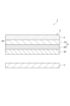
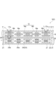
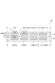
- FIG. 1 is a cross-sectional view illustrating a display device according to the first embodiment.
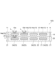
- FIG. 2 is a cross-sectional view that illustrates a pattern printed layer included in the display device shown in FIG.
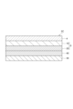
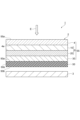
- FIG. 3 is a cross-sectional view illustrating a printed matter according to the first embodiment.
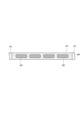
- FIG. 4 is a cross-sectional view that illustrates a white pattern layer provided in the printed matter illustrated in FIG.
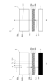
- FIG. 5 is a cross-sectional view that illustrates a printed matter according to the first to third embodiments.
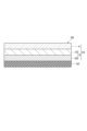
- FIG. 6 is a cross-sectional view that illustrates a printed matter according to the first to fourth embodiments.
- FIG. 7 is a cross-sectional view that illustrates a pattern printed layer included in the display device according to the second embodiment.
- FIG. 8 is a table showing the configurations of the printed matter according to the first to third experimental examples.
- FIG. 9 is a cross-sectional view that illustrates a pattern printed layer included in the display device according to the third embodiment.
- FIG. 1A is a schematic diagram showing color combinations of a picture-printed layer
- FIG. 1B is a schematic diagram showing color combinations of a picture-printed layer according to a comparative example.
- 5A to 5C are schematic diagrams showing specific examples of color combinations of the picture print layer.
- FIG. 12 is a cross-sectional view that illustrates a pattern printed layer included in the display device according to the embodiment 4-1.
- FIG. 1A is a schematic diagram showing color combinations of a picture-printed layer
- FIG. 1B is a schematic diagram showing color combinations of a picture-printed layer according to a comparative example.
- 5A to 5C are schematic diagrams showing specific examples of color combinations of the picture print layer.
- FIG. 15 is a cross-sectional view illustrating a display device according to the fifth embodiment.
- FIG. 16 is a schematic diagram for explaining the operation of the display device according to the 5-1 embodiment.
- FIG. 17 is a schematic diagram for explaining the operation of a display device according to a comparative example.
- 1 is a table showing comparative examples and the conditions of the examples.
- FIG. 19 is a cross-sectional view illustrating a printed matter according to the fifth embodiment.
- FIG. 20 is a cross-sectional view illustrating a printed matter according to the fifth embodiment.
- FIG. 19 is a cross-sectional view illustrating a printed matter according to the fifth embodiment.
- FIG. 21 is a cross-sectional view illustrating a printed matter according to the fifth embodiment.
- FIG. 22 is a cross-sectional view illustrating a decorative panel according to an embodiment of the present disclosure.
- FIG. 23 is a cross-sectional view illustrating a display device according to an embodiment of the present disclosure.
- FIG. 24 is a cross-sectional view showing a schematic diagram of a display device according to a modified example.
- FIG. 25 is a cross-sectional view showing a schematic example of a specific structure of the picture layer.
- FIG. 26 is a cross-sectional view illustrating a decorative panel according to a modified example.
- FIG. 27 is a cross-sectional view illustrating a decorative panel according to a modified example.
- FIG. 28 is a cross-sectional view that shows a schematic diagram of a decorative panel according to a comparative example.
- FIG. 29 is a cross-sectional view that illustrates a display device according to a comparative example.
- FIG. 30 is a cross-sectional view that illustrates a display device according to a comparative example.
- the printed matter described in Japanese Patent No. 5725581 includes a first color pattern layer, a second color pattern layer, and a third color pattern layer, and the pigment chips contained in each pattern layer are either a red interference pigment, a green interference pigment, or a blue interference pigment.
- the number of pattern layers is increased in order to make the colors more vivid than in conventional printing.
- the decorative sheet described in Japanese Patent No. 6839319 includes a first pattern layer containing multiple types of interference pigments and presenting a first mixed color, and a second pattern layer containing multiple types of interference pigments and presenting a second mixed color different from the first mixed color.
- each of the first pattern layer and the second pattern layer contains multiple types of interference pigments, there is a risk that color matching and registration work during printing will become complicated.
- the present disclosure is intended to solve the above-mentioned problems, and aims to provide a printed matter that can express a three-dimensional image even with a small number of printing layers, and can simplify color matching and registration work during printing.
- the present disclosure relates to a printed matter comprising a translucent substrate and a picture print layer.
- the picture print layer is provided on one surface of the translucent substrate and has a first color pattern layer composed of a plurality of first color dots, and a second color pattern layer is provided on the first color pattern layer and composed of a plurality of second color dots.
- each of the multiple first color dots includes a first color binder and multiple first color pigment chips dispersed inside the first color binder
- each of the multiple second color dots includes a second color binder and multiple second color pigment chips dispersed inside the second color binder
- one of the multiple first color pigment chips and the multiple second color pigment chips is a multiple color first interference pigment that generates a first interference light that is different from the other
- the other of the multiple first color pigment chips and the multiple second color pigment chips is a second interference pigment that generates a single color second interference light that is different from the mixed color indicated by the multiple first interference pigments
- the multiple first interference lights and the second interference lights are additively mixed.
- either the first color pattern layer or the second color pattern layer contains interference pigments of multiple colors that generate different interference lights, so a three-dimensional pattern can be realized even with a small number of printed layers.
- the pattern layer containing the interference pigments that generate multiple interference lights can be either the first color pattern layer or the second color pattern layer, so color mixing and registration work during printing can be simplified. Therefore, with this printed matter, a three-dimensional pattern can be expressed even with a small number of printed layers, and color mixing and registration work during printing can be simplified.
- the printed matter of [1] above may further include a white pattern layer formed on the second color pattern layer and composed of a plurality of silver dots, each of which may contain a silver binder and a plurality of silver pigment chips dispersed within the silver binder.
- a white pattern layer formed on the second color pattern layer and composed of a plurality of silver dots, each of which may contain a silver binder and a plurality of silver pigment chips dispersed within the silver binder.
- the color development of the first color pattern layer and the second color pattern layer is excellent, and the pattern printing layer may have a pattern that gives a whitish impression.
- the printed matter of [1] or [2] above may further include a translucent smoke print layer provided on the outermost surface on the side opposite the translucent substrate side with respect to the picture print layer.
- a translucent smoke print layer provided on the outermost surface on the side opposite the translucent substrate side with respect to the picture print layer.
- the color development of the first color pattern layer and the second color pattern layer is more excellent.
- the translucent smoke print layer has transparency, the decrease in visibility of the image on the display device is effectively suppressed.
- the first interference pigment and the second interference pigment may each contain titanium dioxide-coated mica having a particle size of 25 ⁇ m or more and 60 ⁇ m or less.
- titanium dioxide-coated mica having a particle size of 25 ⁇ m or more is contained, the transparency and color development of the picture print layer can be improved.
- titanium dioxide-coated mica having a particle size of 60 ⁇ m or less is contained, a decrease in the resolution and gradation of the picture print layer can be suppressed.
- the content of the multiple first color pigment chips may be in the range of 0.5 parts by weight to 20 parts by weight, when the binder for the first color is 100 parts by weight, and the content of the multiple second color pigment chips may be in the range of 0.5 parts by weight to 20 parts by weight, when the binder for the second color is 100 parts by weight.
- the content of the multiple first color pigment chips is in the range of 0.5 parts by weight or more, the pattern of the first color pattern layer is well expressed.
- the coating property and transparency of the first color pattern layer can be suppressed from decreasing.
- the content of the multiple second color pigment chips is in the range of 0.5 parts by weight to 20 parts by weight
- the binder for the second color is 100 parts by weight
- the pattern of the second color pattern layer is well expressed, while the coating property and transparency of the second color pattern layer can be suppressed from decreasing.
- the present disclosure relates to a display device.
- This display device includes any one of the printed matter [1] to [5] above and a light source. With this display device, when the light source is not lit, the pattern on the pattern printing layer is visible, and when the light source is lit, the transmitted light from the light source (pattern display, video display, etc.) is visible.
- the light source may be a display device.
- the display device when the display is not lit, the pattern on the pattern printing layer is visible, and when the display is lit, the transmitted light from the display (pattern display, image display, etc.) is visible.
- This disclosure makes it possible to provide printed matter that can express a three-dimensional image even with a small number of printing layers, and that can simplify color matching and registration work during printing.
- FIG. 1 is a cross-sectional view showing a display device according to the embodiment 1-1.
- FIG. 2 is a cross-sectional view showing a pattern printed layer included in the display device shown in FIG. 1.
- the display device 1 includes a printed matter 2 and a light source 3.
- the printed matter 2 is a sheet for expressing a pattern, and includes a light-transmitting substrate 4, a pattern printed layer 5, and a transparent smoke printed layer 30.
- the printed matter 2 is provided in front of the light source 3 (between the viewer and the light source 3).
- the printed matter 2 has total light transmittance.
- the light source 3 is, for example, a display device.
- the light-transmitting substrate 4 is a substrate that is transparent to visible light.
- the light-transmitting substrate 4 is made of, for example, a transparent resin. Examples of transparent resins include PET, PMMA, polycarbonate, polyethylene, polypropylene, and nylon.
- the light-transmitting substrate 4 may be a glass substrate.
- the thickness of the light-transmitting substrate 4 is, for example, 25 ⁇ m to 250 ⁇ m, but substrates having a thickness below or above this range may also be used as long as printing is possible. In the case of a glass substrate, the thickness is, for example, several mm to about 10 mm. If necessary, a surface protection layer may be provided on the surface side of the light-transmitting substrate 4 (the side opposite to the pattern printing layer 5).
- the pattern printed layer 5 is a layer that expresses the pattern of the printed matter 2.
- the pattern printed layer 5 includes a first color pattern layer 10 provided on one surface 4a of the light-transmitting substrate 4, and a second color pattern layer 20 provided on the first color pattern layer 10.
- the first color pattern layer 10 can be provided on the surface 4a by, for example, screen printing, inkjet printing, gravure printing, or offset printing. As shown in FIG. 2, the first color pattern layer 10 is composed of a plurality of first color dots 11.
- dots means a point that is an element that constitutes a printed image, and its shape is not limited to a circle, but may be a rectangle, a polygon, or other shape.
- Each of the plurality of first color dots 11 includes a first color binder 12 and a plurality of first color pigment chips 13 dispersed inside the first color binder 12.
- the content of the plurality of first color pigment chips 13 is, for example, in the range of 0.5 parts by weight to 20 parts by weight, assuming that the first color binder 12 is 100 parts by weight.
- the first color binder 12 examples include vinyl resins, acrylic resins, thermoplastic urethane resins, polyester resins, polycarbonate resins, etc.
- the thickness of the first color pattern layer 10 is, for example, 1 ⁇ m to 10 ⁇ m.
- the first color pattern layer 10 may contain a hardener. In this case, the heat resistance of the first color pattern layer 10 and the adhesion of the first color pattern layer 10 to the light-transmitting substrate 4 can be improved.
- the first color pattern layer 10 may also contain a weathering agent. As the weathering agent, a known ultraviolet absorber or light stabilizer can be used.
- the multiple first color pigment chips 13 are multiple color first interference pigments 14a, 14b that generate different interference light from each other.
- Each of the first interference pigments 14a, 14b is composed of a thin flake (not shown) that is transparent to visible light and a metal oxide film (not shown) that covers the flake.
- Light that is reflected on the surface of the metal oxide film out of the light incident on the first color pattern layer 10 from the translucent substrate 4 side interferes with light that passes through the metal oxide film and is reflected on the surface of the flake, generating interference light.
- interference light having a desired wavelength can be generated.
- each of the first interference pigments 14a and 14b is titanium dioxide-coated mica.
- the particle size range of the titanium dioxide-coated mica includes, for example, a range of 25 ⁇ m or more and 60 ⁇ m or less.
- particle size means the longest diameter of the particle cross section.
- the flakes that make up the first interference pigments 14a and 14b may be other than mica, and may be, for example, silica, alumina, glass, or polysilicate.
- the metal oxide film that makes up the first interference pigments 14a and 14b may be other than titanium dioxide, and may be, for example, zirconium oxide, zinc oxide, iron oxide, or tin oxide.
- the first interference pigments 14a and 14b When the incident light E is incident on the first color pattern layer 10, the first interference pigments 14a and 14b generate first interference lights 15a and 15b that are different from each other. That is, the wavelengths of the first interference lights 15a and 15b are different from each other. As a result, the first interference pigments 14a and 14b exhibit a mixed color.
- the first interference pigments 14a and 14b are, for example, a red interference pigment (red pearl pigment) and a gold interference pigment (gold pearl pigment), respectively. In this case, the first interference lights 15a and 15b exhibit red and gold, respectively.
- the blending amounts of the first interference pigments 14a and 14b may be the same or different from each other.
- the second color pattern layer 20 can be provided on the first color pattern layer 10 by, for example, screen printing, inkjet printing, gravure printing, or offset printing. As shown in FIG. 2, the second color pattern layer 20 is composed of a plurality of second color dots 21.
- dots means a point that is an element that constitutes a printed image, and its shape is not limited to a circle, but may be a rectangle, a polygon, or other shape.
- Each of the plurality of second color dots 21 includes a second color binder 22 and a plurality of second color pigment chips 23 dispersed inside the second color binder 22.
- the content of the plurality of second color pigment chips 23 is, for example, in the range of 0.5 parts by weight to 20 parts by weight, assuming that the second color binder 22 is 100 parts by weight.
- the second color binder 22 examples include vinyl resins, acrylic resins, thermoplastic urethane resins, polyester resins, polycarbonate resins, etc.
- the thickness of the second color pattern layer 20 is, for example, 1 ⁇ m to 10 ⁇ m.
- the second color pattern layer 20 may contain a hardener. In this case, the heat resistance of the second color pattern layer 20 and the adhesion of the second color pattern layer 20 to the first color pattern layer 10 can be improved.
- the second color pattern layer 20 may also contain a weathering agent. As the weathering agent, a known ultraviolet absorber or light stabilizer can be used.
- the multiple second color pigment chips 23 are second interference pigments 24 that generate monochromatic interference light different from the mixed color represented by the first interference pigments 14a, 14b.
- the second interference pigment 24 is composed of a thin flake (not shown) that is transparent to visible light, and a metal oxide film (not shown) that covers the flake. Light that is reflected on the surface of the metal oxide film out of the light incident on the second color pattern layer 20 from the translucent substrate 4 side interferes with light that passes through the metal oxide film and is reflected on the surface of the flake, generating interference light. By adjusting the film thickness and the refractive index of the metal oxide film, interference light having a desired wavelength can be generated.
- the second interference pigment 24 is titanium dioxide-coated mica.
- the particle size range of the titanium dioxide-coated mica includes, for example, a range of 25 ⁇ m or more and 60 ⁇ m or less. Note that here, "particle size" means the longest diameter of the particle cross section.
- the flakes constituting the second interference pigment 24 may be other than mica, and may be, for example, silica, alumina, glass, or polysilicate.
- the metal oxide film constituting the second interference pigment 24 may be other than titanium dioxide, and may be, for example, zirconium oxide, zinc oxide, iron oxide, or tin oxide.
- the second interference pigment 24 When the incident light E is incident on the second color pattern layer 20, the second interference pigment 24 generates a monochromatic second interference light 25. As a result, the second interference pigment 24 exhibits a monochromatic color.
- the second interference pigment 24 may be any interference pigment that generates a monochromatic second interference light 25 different from the mixed color exhibited by the first interference pigments 14a, 14b, and may be, for example, a green interference pigment (green pearl pigment). In this case, the second interference light 25 exhibits green color.
- the transparent smoke printed layer 30 has the function of attenuating light from the front side of the viewpoint that passes through the printed matter 2.
- the transparent smoke printed layer 30 is provided on the outermost surface of the picture printed layer 5 on the opposite side to the translucent substrate 4.
- the transparent smoke printed layer 30 is provided on the second color pattern layer 20 as shown in FIG. 1.
- the transparent smoke printed layer 30 can be provided on the second color pattern layer 20 by, for example, screen printing, inkjet printing, gravure printing, or offset printing using an ink in which a small amount of carbon black is dispersed in a resin binder such as a vinyl-based, acrylic-based, urethane-based, or polyester-based resin binder.
- the thickness of the transparent smoke printed layer 30 is, for example, 1 ⁇ m to 10 ⁇ m.
- the transparent smoke printed layer 30 may contain a hardener. In this case, the heat resistance of the transparent smoke printed layer 30 and the adhesion of the transparent smoke printed layer 30 to the second color pattern layer 20 can be improved.
- the transparent smoke print layer 30 may also contain a weathering agent. Known ultraviolet absorbing agents and light stabilizers can be used as weathering agents.
- the pattern is expressed by additively mixing the first interference light 15a, 15b generated by the first interference pigments 14a, 14b and the second interference light 25 generated by the second interference pigment 24.
- the total light transmittance of the printed matter 2 is, for example, 30% to 70%.
- the total light transmittance here refers to the value measured using a spectrophotometer (for example, the UV-2100 spectrophotometer manufactured by Shimadzu Corporation).
- the first color pattern layer 10 contains the first interference pigments 14a, 14b, and the second color pattern layer 20 contains the second interference pigment 24, so that a three-dimensional pattern can be realized even with a small number of printed layers.
- the first color pattern layer 10 is the only pattern layer of the first color pattern layer 10 and the second color pattern layer 20 that contains an interference pigment that generates different interference light, so that color matching and registration work during printing can be simplified. Therefore, with the printed matter 2, a three-dimensional pattern can be expressed even with a small number of printed layers, and color matching and registration work during printing can be simplified.
- the printed matter 2 includes a transparent smoke print layer 30 provided on the second color pattern layer 20. This provides better color development between the first color pattern layer 10 and the second color pattern layer 20. Furthermore, because the transparent smoke print layer 30 is transparent, the decrease in visibility of the image on the display device 1 is effectively suppressed.
- each of the first interference pigments 14a, 14b and the second interference pigment 24 contains titanium dioxide-coated mica with a particle size of 25 ⁇ m or more and 60 ⁇ m or less.
- titanium dioxide-coated mica with a particle size of 25 ⁇ m or more is contained, the transparency and color development of the picture-printed layer 5 can be improved.
- titanium dioxide-coated mica with a particle size of 60 ⁇ m or less is contained, a decrease in the resolution and gradation of the picture-printed layer 5 can be suppressed.
- the content of the multiple first color pigment chips 13 is in the range of 0.5 parts by weight or more and 20 parts by weight or less when the first color binder 12 is 100 parts by weight
- the content of the multiple second color pigment chips 23 is in the range of 0.5 parts by weight or more and 20 parts by weight or less when the second color binder is 100 parts by weight. Since the content of the multiple first color pigment chips 13 is in the range of 0.5 parts by weight or more, the pattern of the first color pattern layer 10 is well expressed. Since the content of the multiple first color pigment chips 13 is in the range of 20 parts by weight or less, a decrease in the coating properties and permeability of the first color pattern layer 10 can be suppressed.
- the content of the multiple second color pigment chips 23 is within the range of 0.5 parts by weight to 20 parts by weight, assuming that the second color binder 22 is 100 parts by weight, so that the pattern of the second color pattern layer 20 is well expressed while preventing a decrease in the coating properties and transparency of the second color pattern layer 20.
- the total light transmittance of the printed matter 2 is 30% to 70%. If the total light transmittance is 30% or more, when the printed matter 2 is placed in front of a screen, the light of the image on the screen makes it difficult to see the picture printed layer 5, and the image is more clearly visible. If the total light transmittance is 70% or less, the picture on the picture printed layer 5 is prevented from appearing dark even if the screen is black.
- the display device 1 includes a printed matter 2 and a light source 3. With the display device 1, when the light source 3 is not lit, the pattern on the pattern printing layer 5 is visible, and when the light source 3 is lit, the transmitted light from the light source 3 (pattern display, image display, etc.) is visible.
- the light source 3 may be a display device.
- the pattern on the pattern printing layer 5 is visible, and when the display is turned on, the transmitted light from the display (pattern display, image display, etc.) is visible.
- the multiple interference pigments 14a, 14b, 24 may contain pearl pigments.
- the picture printed layer 5 may contain multiple interference pearl pigments (interference pigments 14a, 14b, 24) that are different from each other.
- the printed matter 2 is a printed matter 2 that includes a translucent substrate 4 and a picture printed layer 5, and the picture printed layer 5 may contain multiple interference pearl pigments. This allows the picture printed layer 5 to produce a three-dimensional expression.
- the pattern print layer 5 may include a first color pattern layer 10 containing an interference pearl pigment, and a second color pattern layer 20 containing an interference pearl pigment. This allows the pattern print layer 5 to produce an even more three-dimensional expression.
- the first color pattern layer 10 and the second color pattern layer 20 may each contain a plurality of interference pearl pigments. This allows the picture print layer 5 to produce an even more three-dimensional expression.
- the second color pattern layer 20 may contain other interference pearl pigments in addition to the interference pigment 24.
- the particle sizes of the multiple interference pearl pigments may be different from each other. In this way, by including interference pearl pigments with different particle sizes, the decrease in transparency of the picture print layer 5 is suppressed.
- the particle size of the multiple interference pearl pigments may be 25 ⁇ m or more and 60 ⁇ m or less. In this case, the color development of the pattern of the pattern printed layer 5 can be improved. In addition, by suppressing unnecessary reduction in the transparency of the pattern printed layer 5, the visibility of the image on the display device can be improved when used in a display device.
- the interference pearl pigment may contain titanium dioxide-coated mica.
- the wavelength of the interference light can be adjusted by adjusting the thickness of the titanium dioxide film.
- the sense of brilliance can be improved by increasing the smoothness of the mica surface.
- the effect of the picture-printed layer 5 containing multiple interference pearl pigments can be obtained not only in the first disclosure, but also in the second to sixth disclosures described below.
- FIG. 3 is a cross-sectional view that shows a schematic representation of a printed matter according to embodiment 1-2.
- FIG. 4 is a cross-sectional view that shows a schematic representation of a white pattern layer that the printed matter shown in FIG. 3 has.
- the printed matter 2A has a light-transmitting substrate 4 and a picture print layer 5.
- the printed matter 2A further has a white pattern layer 40 provided on the second color pattern layer 20.
- the white pattern layer 40 can be provided on the second color pattern layer 20 by, for example, screen printing, inkjet printing, gravure printing, or offset printing. As shown in FIG. 4, the white pattern layer 40 is composed of a plurality of silver dots 41.
- dot means a point that is an element that constitutes a printed image, and the shape is not limited to a circle, but may be a rectangle, a polygon, or other shape.
- Each of the plurality of silver dots 41 contains a silver binder 42 and a plurality of silver pigment chips 43 dispersed inside the silver binder 42.
- the content of the plurality of silver pigment chips 43 is, for example, in the range of 0.5 parts by weight to 20 parts by weight, assuming that the silver binder 42 is 100 parts by weight.
- the silver binder 42 examples include vinyl resins, acrylic resins, thermoplastic urethane resins, polyester resins, and polycarbonate resins.
- the thickness of the white pattern layer 40 is, for example, 1 ⁇ m to 10 ⁇ m.
- the white pattern layer 40 may contain a hardener. In this case, the heat resistance of the white pattern layer 40 and the adhesion of the white pattern layer 40 to the second color pattern layer 20 can be improved.
- the white pattern layer 40 may also contain a weathering agent. As the weathering agent, a known ultraviolet absorber or light stabilizer can be used.
- embodiment 1-2 includes a white pattern layer 40 that is provided on the second color pattern layer 20 and is composed of a plurality of silver dots 41, and each of the plurality of silver dots 41 contains a silver binder 42 and a plurality of silver pigment chips 43 dispersed within the silver binder 42. This allows the color development of the first color pattern layer 10 and the second color pattern layer 20 to be excellent, and the picture printed layer 5 to have a pattern that gives a whitish impression.
- FIG. 5 is a cross-sectional view showing a schematic of a printed matter according to embodiment 1-3.
- Printed matter 2B comprises a light-transmitting substrate 4 and a picture print layer 5.
- printed matter 2B does not comprise a translucent smoke print layer 30 and a white pattern layer 40. Even with the configuration of printed matter 2B described above, the same effects as those of embodiment 1-1 can be achieved.
- FIG. 6 is a cross-sectional view showing a schematic representation of a printed matter according to embodiment 1-4.
- Printed matter 2C comprises a translucent substrate 4, a picture print layer 5, a white pattern layer 40, and a translucent smoke print layer 30.
- the white pattern layer 40 is provided on the second color pattern layer 20, and the translucent smoke print layer 30 is provided on the white pattern layer 40.
- the second color pattern layer may include a first interference pigment of multiple colors that generate different first interference lights
- the first color pattern layer may include a second interference pigment that generates a single-color second interference light that is different from the mixed color exhibited by the multiple first interference pigments.
- the first color pigment chip is a first interference pigment of two colors, but the first color pigment chip may be a first interference pigment of three or more colors.
- the color development of the pattern may be deteriorated depending on the particle size of the interference pigment.
- a printed matter having excellent color development is desired so that the viewer can easily recognize the color of the picture.
- the printed matter described in Japanese Patent No. 6839319 may be placed in front of a display device having a display that turns black when the power is off. In this case, when the power is off, the picture of the printed matter may look dark, and the visibility of the picture may be deteriorated.
- the present disclosure is intended to solve the above-mentioned problems, and aims to provide printed matter and display devices having patterns with excellent visibility and color development.
- the present disclosure relates to a printed matter comprising a translucent substrate and a pattern printed layer.
- the pattern printed layer is provided on one surface of the translucent substrate and has a first color pattern layer composed of a plurality of first color dots, and a second color pattern layer is provided on the first color pattern layer and composed of a plurality of second color dots.
- each of the plurality of first color dots includes a first color binder and a plurality of first color pigment chips dispersed inside the first color binder
- each of the plurality of second color dots includes a second color binder and a plurality of second color pigment chips dispersed inside the second color binder.
- Either one of the plurality of first color pigment chips and the plurality of second color pigment chips is a first interference pigment of a plurality of colors that generates first interference light different from each other, and the other of the plurality of first color pigment chips and the plurality of second color pigment chips is a second interference pigment that generates a single-color second interference light different from the mixed color indicated by the plurality of first interference pigments.
- At least one of the first and second interference pigments contains a small particle grade interference pigment with a particle size range of 5 ⁇ m to 25 ⁇ m and a large particle grade interference pigment with a particle size range of 25 ⁇ m to 40 ⁇ m, and the small particle grade interference pigment is arranged to fill the gaps between the large particle grade interference pigments, and a plurality of first interference lights and second interference lights are additively mixed.
- the present inventors have come up with a printed matter in which the pattern is suppressed from appearing dark and the color development of the pattern is excellent by configuring an interference pigment to include a small particle diameter grade interference pigment and a large particle diameter grade interference pigment, and arranging the small particle diameter grade interference pigment so as to fill the gaps between the large particle diameter grade interference pigments.
- a printed matter having the above configuration can provide a pattern with excellent visibility and color development. Furthermore, in this printed matter, by including a large particle diameter grade interference pigment, the decrease in the transparency of the pattern printing layer is suppressed. Therefore, with this printed matter, the decrease in the visibility of the image on the display device is effectively suppressed when the power is on.
- the large particle grade interference pigment may have a particle size range of 25 ⁇ m to 60 ⁇ m.
- the color development of the pattern can be improved.
- the visibility of the image on the display device can be improved when used.
- At least one of the small particle grade interference pigment and the large particle grade interference pigment may be an interference pigment containing titanium dioxide-coated mica.
- the wavelength of the interference light can be adjusted by adjusting the film thickness of the titanium dioxide film.
- the sense of brilliance can be improved by increasing the smoothness of the mica surface.
- any of the printed matter [1] to [3] above may further include a white pattern layer formed on the second color pattern layer and composed of a plurality of silver dots, each of which may contain a silver binder and a plurality of silver pigment chips dispersed within the silver binder.
- the color development of the first color pattern layer and the second color pattern layer is superior, and the pattern printing layer may have a pattern that gives a whitish impression.
- Any of the printed matter [1] to [4] above may further include a translucent smoke print layer provided on the outermost surface of the picture print layer on the side opposite the translucent substrate.
- a translucent smoke print layer provided on the outermost surface of the picture print layer on the side opposite the translucent substrate.
- the color development of the first color pattern layer and the second color pattern layer is more excellent.
- the translucent smoke print layer has transparency, the decrease in visibility of the image on the display device is effectively suppressed.
- the present disclosure relates to a display device.
- This display device includes any one of the printed matter [1] to [5] above and a light source. With this display device, when the light source is not lit, the pattern on the pattern printing layer is visible, and when the light source is lit, the transmitted light from the light source (pattern display, video display, etc.) is visible.
- the light source may be a display device.
- the display device when the display is not lit, the pattern on the pattern printing layer is visible, and when the display is lit, the transmitted light from the display (pattern display, image display, etc.) is visible.
- This disclosure makes it possible to provide printed matter and display devices with patterns that have excellent visibility and color development.
- the printed matter and display device according to this embodiment may have a configuration similar to that shown in Fig. 1. Therefore, in the printed matter and display device according to this embodiment, the description of the configuration similar to that of the printed matter and display device of the 1-1 embodiment will be omitted.
- the printed matter and display device according to the 2-1 embodiment adopts the layer configuration shown in Fig. 7 instead of the layer configuration shown in Fig. 2.
- the first interference pigment 14a includes a plurality of first titanium dioxide-coated micas 18a of a small particle size grade including a particle size range of 5 ⁇ m to 25 ⁇ m, and a second titanium dioxide-coated mica 18b of a large particle size grade including a particle size range of 25 ⁇ m to 40 ⁇ m.
- the first interference pigment 14b includes a plurality of first titanium dioxide-coated micas 16a of a small particle size grade including a particle size range of 5 ⁇ m to 25 ⁇ m, and a plurality of second titanium dioxide-coated micas 16b of a large particle size grade including a particle size range of 25 ⁇ m to 40 ⁇ m.
- the average particle size (D50) of the first titanium dioxide-coated micas 18a, 16a is, for example, about 15 ⁇ m
- the average particle size (D50) of the second titanium dioxide-coated micas 18b, 16b is, for example, about 25 ⁇ m.
- the second titanium dioxide coated mica 18b, 16b may have a particle size range of 25 ⁇ m to 60 ⁇ m.
- the average particle size (D50) of the second titanium dioxide coated mica 18b, 16b is, for example, about 35 ⁇ m.
- each of the multiple first titanium dioxide coated mica 18a, 16a is arranged so as to fill the gaps between the multiple second titanium dioxide coated mica 18b, 16b.
- particle size means the longest diameter of the particle cross section.
- the first interference pigments 14a and 14b When the incident light L is incident on the first color pattern layer 10, the first interference pigments 14a and 14b generate first interference lights 17a and 17b that are different from each other. That is, the wavelengths of the first interference lights 17a and 17b are different from each other. As a result, the first interference pigments 14a and 14b exhibit a mixed color.
- the first interference pigments 14a and 14b may be, for example, a red interference pigment (red pearl pigment) and a gold interference pigment (gold pearl pigment), respectively. In this case, the first interference lights 17a and 17b exhibit red and gold, respectively.
- the first interference pigments 14a and 14b may be interference pigments of other colors. The blending amounts of the first interference pigments 14a and 14b may be the same or different from each other.
- the second color pattern layer 20 may be the same as that shown in the first disclosure.
- the second interference pigment 24 includes a plurality of first titanium dioxide-coated mica 25a of a small particle size grade including a particle size range of 5 ⁇ m to 25 ⁇ m, and a second titanium dioxide-coated mica 25b of a large particle size grade including a particle size range of 25 ⁇ m to 40 ⁇ m.
- the average particle size (D50) of the first titanium dioxide-coated mica 25a is, for example, about 15 ⁇ m
- the average particle size (D50) of the second titanium dioxide-coated mica 25b is, for example, about 25 ⁇ m.
- the average particle size of the first titanium dioxide-coated mica 25a is smaller than the average particle size of the second titanium dioxide-coated mica 25b.
- the second titanium dioxide-coated mica 25b may include a particle size range of 25 ⁇ m to 60 ⁇ m.
- the average particle size (D50) of the second titanium dioxide-coated mica 25b is, for example, about 35 ⁇ m.
- Each of the multiple first titanium dioxide-coated mica 25a is arranged to fill the gaps between the multiple second titanium dioxide-coated mica 25b.
- particle size means the longest diameter of the particle cross section.
- the second interference pigment 24 When the incident light L is incident on the second color pattern layer 20, the second interference pigment 24 generates a monochromatic second interference light 26. As a result, the second interference pigment 24 exhibits a monochromatic color.
- the second interference pigment 24 may be any interference pigment that generates a monochromatic second interference light 26 different from the mixed color exhibited by the first interference pigments 14a, 14b, and may be, for example, a green interference pigment (green pearl pigment). In this case, the second interference light 26 exhibits green. Note that the second interference pigment 24 may be an interference pigment of a color other than green.
- the transparent smoke printed layer 30 is a layer for attenuating the light transmitted through the printed matter 2.
- the transparent smoke printed layer 30 is provided on the outermost surface of the picture printed layer 5 on the opposite side to the light-transmitting substrate 4.
- the transparent smoke printed layer 30 is provided on the second color pattern layer 20 as shown in FIG. 1.
- the transparent smoke printed layer 30 can be provided on the second color pattern layer 20 by, for example, screen printing, inkjet printing, gravure printing, or offset printing using an ink in which a small amount of carbon black is dispersed in a resin binder such as a vinyl-based, acrylic-based, urethane-based, or polyester-based resin binder.
- the thickness of the transparent smoke printed layer 30 is, for example, 1 ⁇ m to 10 ⁇ m.
- the transparent smoke printed layer 30 may contain a hardener. In this case, the heat resistance of the transparent smoke printed layer 30 and the adhesion of the transparent smoke printed layer 30 to the second color pattern layer 20 can be improved.
- the transparent smoke print layer 30 may also contain a weathering agent. Known ultraviolet absorbing agents and light stabilizers can be used as weathering agents.
- the pattern is expressed by additively mixing the first interference light 17a, 17b generated by the first interference pigments 14a, 14b and the second interference light 26 generated by the second interference pigment 24.
- the total light transmittance of the printed matter 2 is, for example, 30% to 70%.
- the total light transmittance here refers to the value measured using a spectrophotometer (for example, the UV-2100 spectrophotometer manufactured by Shimadzu Corporation).
- each of the plurality of first titanium dioxide-coated micas 18a, 16a having a small particle diameter grade including a particle diameter range of 5 ⁇ m to 25 ⁇ m is arranged so as to fill the gaps between the plurality of second titanium dioxide-coated micas 18b, 16b having a large particle diameter grade including a particle diameter range of 25 ⁇ m to 40 ⁇ m.
- each of the plurality of first titanium dioxide-coated micas 25a having a small particle diameter grade including a particle diameter range of 5 ⁇ m to 25 ⁇ m is arranged so as to fill the gaps between the plurality of second titanium dioxide-coated micas 25b having a large particle diameter grade including a particle diameter range of 25 ⁇ m to 40 ⁇ m. Therefore, the printed matter 2 can provide a pattern with excellent visibility and color development. Furthermore, in the printed matter 2, the first color pattern layer 10 contains second titanium dioxide-coated mica 18b, 16b of large particle size grade, and the second color pattern layer 20 contains second titanium dioxide-coated mica 25b of large particle size grade, thereby suppressing the decrease in transparency of the picture print layer 5. Therefore, according to the printed matter 2, when the power is on, the decrease in visibility of the image on the display device is effectively suppressed.
- the large particle grade second titanium dioxide coated mica 18b, 16b, 25b may be configured to have a particle size range of 25 ⁇ m to 60 ⁇ m. In this case, the color development of the pattern is more excellent. In addition, by suppressing unnecessary reduction in the transparency of the pattern printed layer 5, the visibility of the image on the display device 1 can be improved when the display device is used.
- the first interference pigments 14a, 14b and the second interference pigment 24 are interference pigments containing titanium dioxide-coated mica. Therefore, by adjusting the thickness of the titanium dioxide film, it is possible to adjust the wavelength of the interference light. In addition, by increasing the smoothness of the mica surface, it is possible to improve the sense of luminance.
- the first interference pigment and the second interference pigment each contain a plurality of first titanium dioxide-coated micas and a plurality of second titanium dioxide-coated micas, but it is sufficient that at least one of the first interference pigment and the second interference pigment contains a plurality of first titanium dioxide-coated micas and a plurality of second titanium dioxide-coated micas.
- the first color pigment chip is a first interference pigment of two colors, but the first color pigment chip may be a first interference pigment of three or more colors. Also, the first interference pigments of multiple colors may be mixed together.
- FIG. 8 is a diagram showing the structure of the printed matter according to Experimental Examples 1 to 3.
- a LCD monitor was placed on the back side (transparent smoke printed layer side) of the printed matter according to Experimental Examples 1 to 3.
- the distance between the printed matter and the LCD monitor was 2 mm.
- the visibility (items 1 to 4 described later) of the LCD monitor when it was turned on and off was evaluated. Sensory evaluation was performed by four people for items 1 to 4, and the average score was calculated.
- Example 1 A printed matter was produced by providing a first color pattern layer, a second color pattern layer, a white pattern layer, and a transparent smoke print layer in this order on a transparent substrate made of transparent PET.
- a first color pattern layer was formed by screen printing technology using an ink containing a first color binder (urethane resin) and a red interference pigment and a gold interference pigment dispersed inside the first color binder.
- the contents of the red interference pigment and the gold interference pigment were 8 parts by weight of a red interference pigment having a particle size of 10 to 40 ⁇ m, 2 parts by weight of a red interference pigment having a particle size of 5 to 25 ⁇ m, 5 parts by weight of a gold interference pigment having a particle size of 10 to 60 ⁇ m, and 2 parts by weight of a gold interference pigment having a particle size of 5 to 25 ⁇ m, when the first color binder was taken as 100 parts by weight.
- a second color pattern layer was formed by screen printing technology using an ink containing a second color binder (urethane resin) and a green interference pigment dispersed inside the second color binder.
- the green interference pigment content was 4 parts by weight of a green interference pigment with a particle size of 10 to 40 ⁇ m and 1 part by weight of a green interference pigment with a particle size of 5 to 25 ⁇ m, assuming that the second color binder was 100 parts by weight.
- the red interference pigment, gold interference pigment, and green interference pigment were all titanium dioxide-coated mica.
- a white pattern layer was formed by screen printing technology using ink containing a silver binder (urethane resin) and silver pigment chips dispersed inside the silver binder.
- the content of the silver pigment chips was 1 part by weight of silver pigment chips with a particle size of 5 to 25 ⁇ m for every 100 parts by weight of silver binder.
- a transparent smoke print layer was formed by screen printing technology using ink that was a mixture of medium ink and black ink in a ratio of 40:1.
- Example 2 A printed matter was produced by providing a first color pattern layer, a second color pattern layer, a white pattern layer, and a transparent smoke print layer in this order on a transparent substrate made of transparent PET.
- a first color pattern layer was formed by screen printing technology using an ink containing a first color binder (urethane resin) and a red interference pigment and a gold interference pigment dispersed inside the first color binder.
- the contents of the red interference pigment and the gold interference pigment were 8 parts by weight of a red interference pigment having a particle size of 10 to 40 ⁇ m, 2 parts by weight of a red interference pigment having a particle size of 5 to 25 ⁇ m, 5 parts by weight of a gold interference pigment having a particle size of 10 to 60 ⁇ m, and 2 parts by weight of a gold interference pigment having a particle size of 5 to 25 ⁇ m, when the first color binder was taken as 100 parts by weight.
- a second color pattern layer was formed by screen printing technology using an ink containing a second color binder (urethane resin) and a green interference pigment dispersed inside the second color binder.
- the content of the green interference pigment was 4 parts by weight of the green interference pigment having a particle size of 10 to 40 ⁇ m for every 100 parts by weight of the second color binder.
- the red interference pigment, gold interference pigment, and green interference pigment were all titanium dioxide-coated mica.
- a white pattern layer was formed by screen printing technology using ink containing a silver binder (urethane resin) and silver pigment chips dispersed inside the silver binder.
- the content of silver pigment chips was 1 part by weight of silver pigment chips with particle sizes of 5 to 25 ⁇ m for every 100 parts by weight of silver binder.
- a transparent smoke print layer was formed by screen printing technology using ink that was a mixture of medium ink and black ink in a ratio of 40:1.
- Example 3 A printed matter was produced by providing a first color pattern layer, a second color pattern layer, and a transparent smoke print layer in this order on a transparent substrate made of transparent PET.
- a first color pattern layer was formed by screen printing technology using an ink containing a first color binder (urethane resin) and a green interference pigment dispersed inside the first color binder.
- the content of the green interference pigment was 4 parts by weight of a green interference pigment having a particle size of 10 to 40 ⁇ m and 1 part by weight of a green interference pigment having a particle size of 5 to 25 ⁇ m, when the first color binder was taken as 100 parts by weight.
- a second color pattern layer was formed by screen printing technology using an ink containing a second color binder (urethane resin) and red and gold interference pigments dispersed inside the second color binder.
- the red and gold interference pigment contents were 8 parts by weight of red interference pigment with a particle size of 10 to 40 ⁇ m and 5 parts by weight of gold interference pigment with a particle size of 10 to 60 ⁇ m, assuming that the second color binder was 100 parts by weight.
- ⁇ Item 1 Clarity of displayed content> When the power supply of the liquid crystal monitor was turned on, the clarity of the images and characters displayed on the liquid crystal monitor was evaluated.
- ⁇ Item 2 Brightness of displayed content> When the power supply of the liquid crystal monitor was turned on, the brightness of the images and characters displayed on the liquid crystal monitor was evaluated.
- ⁇ Item 3 Influence of black LCD monitors> The effect of the black LCD monitor on the image when the LCD monitor was turned off was evaluated.
- ⁇ Item 4 Color development of the picture> The color development of the image was evaluated when the power of the liquid crystal monitor was turned off. ⁇ Score> 5 points: The color of the pattern is good. 3 points: The color of the pattern is slightly weak and the color of the pattern appears pale (whitish). 1 point: The color of the pattern is weak and the color of the pattern appears white.
- the printed matter described in Japanese Patent No. 5725581 includes a first color pattern layer, a second color pattern layer, and a third color pattern layer, and the pigment chips contained in each pattern layer are either a red interference pigment, a green interference pigment, or a blue interference pigment.
- the number of pattern layers is increased to make the colors more vivid than in conventional printing.
- the decorative sheet described in Japanese Patent No. 6839319 includes a first pattern layer containing multiple types of interference pigments and presenting a first mixed color, and a second pattern layer containing multiple types of interference pigments and presenting a second mixed color different from the first mixed color.
- the present disclosure is intended to solve the above-mentioned problems, and aims to provide a printed matter that can simplify color matching and registration work during printing.
- the present disclosure relates to a printed matter comprising a translucent substrate and a pattern printed layer.
- the pattern printed layer is provided on one surface of the translucent substrate, and has a first color pattern layer composed of a plurality of first color dots, and a second color pattern layer is provided on the first color pattern layer and composed of a plurality of second color dots.
- each of the plurality of first color dots includes a first color binder and a plurality of first color pigment chips dispersed inside the first color binder
- each of the plurality of second color dots includes a second color binder and a plurality of second color pigment chips dispersed inside the second color binder
- the plurality of first color pigment chips are a first interference pigment that generates a monochromatic first interference light
- the plurality of second color pigment chips are a second interference pigment that generates a monochromatic second interference light different from the color indicated by the first interference pigment
- the first interference light and the second interference light are additively mixed.
- the first color pattern layer contains a first interference pigment that generates a monochromatic first interference light
- the second color pattern layer contains a second interference pigment that generates a monochromatic second interference light different from the color indicated by the first interference pigment.
- the printed matter of [1] above may further include a white pattern layer formed on the second color pattern layer and composed of a plurality of silver dots, each of which may contain a silver binder and a plurality of silver pigment chips dispersed within the silver binder.
- a white pattern layer formed on the second color pattern layer and composed of a plurality of silver dots, each of which may contain a silver binder and a plurality of silver pigment chips dispersed within the silver binder.
- the color development of the first color pattern layer and the second color pattern layer is excellent, and the pattern printing layer may have a pattern that gives a whitish impression.
- the printed matter of [1] or [2] above may further include a translucent smoke print layer provided on the outermost surface on the side opposite the translucent substrate side with respect to the picture print layer.
- a translucent smoke print layer provided on the outermost surface on the side opposite the translucent substrate side with respect to the picture print layer.
- the color development of the first color pattern layer and the second color pattern layer is more excellent.
- the translucent smoke print layer has transparency, the decrease in visibility of the image on the display device is effectively suppressed.
- the present disclosure relates to a display device.
- This display device includes any one of the printed matter [1] to [3] above and a light source. With this display device, when the light source is not lit, the pattern on the pattern printing layer is visible, and when the light source is lit, the transmitted light from the light source (pattern display, image display, etc.) is visible.
- the light source may be a display device.
- the display device when the display is not lit, the pattern on the pattern printing layer is visible, and when the display is lit, the transmitted light from the display (pattern display, image display, etc.) is visible.
- This disclosure makes it possible to provide printed matter that simplifies color matching and registration work during printing.
- the printed matter and display device according to this embodiment may have a configuration similar to that shown in Fig. 1. Therefore, in the printed matter and display device according to this embodiment, the description of the configuration similar to that of the printed matter and display device of the 1-1 embodiment will be omitted.
- the printed matter and display device according to this embodiment adopts the layer configuration shown in Fig. 9 instead of the layer configuration shown in Fig. 2.
- the first color pattern layer 10 can be provided on the surface 4a by, for example, screen printing, inkjet printing, gravure printing, or offset printing. As shown in FIG. 9, the first color pattern layer 10 is composed of a plurality of first color dots 11.
- the "dot" means a point that is an element that constitutes a printed image, and the shape is not limited to a circle, and may be a rectangle, a polygon, or other shape.
- Each of the plurality of first color dots 11 contains a first color binder 12 and a plurality of first color pigment chips 13 dispersed inside the first color binder 12.
- the content of the plurality of first color pigment chips 13 is, for example, in the range of 0.5 parts by weight to 20 parts by weight, assuming that the first color binder 12 is 100 parts by weight.
- the pattern of the first color pattern layer 10 is well expressed, while the deterioration of the coating property and transparency of the first color pattern layer 10 can be suppressed.
- the multiple first color pigment chips 13 are interference pigments 14 (first interference pigments) that generate monochromatic interference light of a predetermined color.
- the interference pigments 14 are composed of flakes (not shown) that are transparent to visible light, and a metal oxide film (not shown) that covers the flakes. Light that is reflected on the surface of the metal oxide film out of the light incident on the first color pattern layer 10 from the translucent substrate 4 side interferes with light that passes through the metal oxide film and is reflected on the surface of the flakes, generating interference light.
- interference light having a desired wavelength can be generated.
- the interference pigment 14 When incident light E is incident on the first color pattern layer 10, the interference pigment 14 generates monochromatic interference light 15 (first interference light). As a result, the interference pigment 14 exhibits a monochromatic color.
- the content of the plurality of second color pigment chips 23 is, for example, in the range of 0.5 parts by weight to 20 parts by weight, assuming that the second color binder 22 is 100 parts by weight.
- the pattern of the second color pattern layer 20 is well expressed, while the deterioration of the coating property and transparency of the second color pattern layer 20 can be suppressed.
- the interference pigment 24 (second interference pigment) generates monochromatic interference light 25 (second interference light). As a result, the interference pigment 24 exhibits a monochromatic color.
- the interference pigment 24 may be any interference pigment that generates monochromatic interference light 25 that is different from the color exhibited by the interference pigment 14.
- Figure 10(a) is a schematic diagram showing the color combinations in the picture-printed layer 5.
- Figure 10(b) is a schematic diagram showing the color combinations in the picture-printed layer 105 according to a comparative example.
- Figure 11 is a schematic diagram showing a specific example of the color combinations in the picture-printed layer 5.
- the first color pattern layer 10 contains an interference pigment of a monochromatic "color A,” which generates interference light of a monochromatic "color A.”
- the second color pattern layer 20 contains an interference pigment of a monochromatic "color B,” which generates interference light of a monochromatic "color B.”
- Color B is a different color from color A. Therefore, in the printed matter 2, the pattern is expressed by additively mixing the interference light of color A and the interference light of color B.
- the interference pigment 14 shown in FIG. 9 is, for example, a gold interference pigment (gold pearl pigment).
- the interference light 15 indicates gold.
- the interference pigment 24 is, for example, a red interference pigment (red pearl pigment).
- the interference light 25 indicates red.
- the printed matter 2 may express a wood grain pattern as a design by additively mixing red and gold. By making the first color pattern layer 10 red, it is possible to express a wood grain with a slightly reddish hue.
- the printed matter 2 may express a hairline pattern as a design by additively mixing silver and gold. By making the second color pattern layer 20 gold, the usual stainless steel hairline can be adjusted to a gold tone.
- the interference pigment 14 shown in FIG. 9 is, for example, a silver interference pigment (silver pearl pigment).
- the interference light 15 shows silver.
- the printed matter 2 may express a hairline pattern as a design by additively mixing silver and red. By making the second color pattern layer 20 red, the stainless steel hairline can be adjusted to a bronze tone.
- the printed matter 2 may express a hairline pattern as a design by additively mixing gold and silver.
- a finish that further emphasizes the gold tone can be achieved.
- the first color pattern layer 10 contains an interference pigment 14 that generates a monochromatic interference light
- the second color pattern layer 20 contains an interference pigment 24 that generates a monochromatic interference light 25 that is different from the color indicated by the interference pigment 14.
- a printed matter 102 is given as an example for comparison, in which the first color pattern layer 10 contains interference pigments of color X and color Y, and the second color pattern layer 20 contains an interference pigment of color Z.
- a pattern such as that described in FIG. 11 is expressed using the configuration of the comparative example, it is necessary to adjust the three colors X, Y, and Z, and the color matching and registration work during printing is time-consuming.
- the printed matter described in Japanese Patent No. 5725581 includes a first color pattern layer, a second color pattern layer, and a third color pattern layer, and the pigment chips contained in each pattern layer are either a red interference pigment, a green interference pigment, or a blue interference pigment.
- the number of pattern layers is increased to make the colors more vivid than in conventional printing.
- the decorative sheet described in Japanese Patent No. 6839319 includes a first pattern layer containing multiple types of interference pigments and presenting a first mixed color, and a second pattern layer containing multiple types of interference pigments and presenting a second mixed color different from the first mixed color.
- the present invention is intended to solve the above-mentioned problems, and aims to provide a printed matter that simplifies color matching and registration work during printing.
- the present invention relates to a printed matter comprising a translucent substrate and a picture print layer.
- the picture print layer is provided on one surface of the translucent substrate and has a first color pattern layer composed of a plurality of first color dots, and a second color pattern layer provided on the first color pattern layer and composed of a plurality of second color dots.
- each of the multiple first color dots includes a first color binder and multiple first color pigment chips dispersed inside the first color binder
- each of the multiple second color dots includes a second color binder and multiple second color pigment chips dispersed inside the second color binder
- one of the multiple first color pigment chips and the multiple second color pigment chips is a multiple-color first interference pigment that generates a first interference light that is different from each other
- the other of the multiple first color pigment chips and the multiple second color pigment chips is a second interference pigment that generates a monochromatic second interference light of the same color as any of the multiple first interference pigments
- the multiple first interference lights and the second interference lights are additively mixed.
- the first color pattern layer or the second color pattern layer contains interference pigments of multiple colors that generate different interference lights, a three-dimensional pattern can be realized even with a small number of printed layers.
- the pattern layer containing the interference pigment that generates multiple interference lights can be any one of the first color pattern layer and the second color pattern layer, so that color matching and registration work during printing can be simplified.
- the other of the first color pattern layer and the second color pattern layer contains a second interference pigment that generates a monochromatic second interference light of the same color as any one of the multiple first interference pigments.
- the pattern for a pattern that can be expressed with a small number of colors, it is possible to express the pattern by the intensity of the monochromatic color by limiting the second interference pigment to the same monochromatic color as the first interference pigment.
- too much interference pigment is added to one color pattern layer, the strength of the coating film decreases, but by using two color pattern layers, this decrease in strength can be suppressed. As a result, color matching and registration work during printing can be simplified.
- the printed matter of [1] above may further include a white pattern layer formed on the second color pattern layer and composed of a plurality of silver dots, each of which may contain a silver binder and a plurality of silver pigment chips dispersed within the silver binder.
- a white pattern layer formed on the second color pattern layer and composed of a plurality of silver dots, each of which may contain a silver binder and a plurality of silver pigment chips dispersed within the silver binder.
- the color development of the first color pattern layer and the second color pattern layer is excellent, and the pattern printing layer may have a pattern that gives a whitish impression.
- the printed matter of [1] or [2] above may further include a translucent smoke print layer provided on the outermost surface on the side opposite the translucent substrate side with respect to the picture print layer.
- a translucent smoke print layer provided on the outermost surface on the side opposite the translucent substrate side with respect to the picture print layer.
- the color development of the first color pattern layer and the second color pattern layer is more excellent.
- the translucent smoke print layer has transparency, the decrease in visibility of the image on the display device is effectively suppressed.
- the present invention relates to a display device.
- This display device includes any one of the printed matter described above in [1] to [3] and a light source. With this display device, when the light source is not lit, the pattern on the pattern printing layer is visible, and when the light source is lit, the transmitted light from the light source (pattern display, image display, etc.) is visible.
- the light source may be a display device.
- the display device when the display is not lit, the pattern on the pattern printing layer is visible, and when the display is lit, the transmitted light from the display (pattern display, image display, etc.) is visible.
- the present invention provides a printed matter that simplifies color matching and registration work during printing.
- the printed matter and display device according to this embodiment may have a configuration similar to that shown in Fig. 1. Therefore, in the printed matter and display device according to this embodiment, the description of the configuration similar to that of the printed matter and display device of the 1-1 embodiment will be omitted.
- the printed matter and display device according to this embodiment adopts the layer configuration shown in Fig. 12 instead of the layer configuration shown in Fig. 2.
- the first color pattern layer 10 can be provided on the surface 4a by, for example, screen printing, inkjet printing, gravure printing, or offset printing. As shown in FIG. 12, the first color pattern layer 10 is composed of a plurality of first color dots 11.
- dots means a point that is an element that constitutes a printed image, and its shape is not limited to a circle, and may be a rectangle, a polygon, or other shape.
- Each of the plurality of first color dots 11 contains a first color binder 12 and a plurality of first color pigment chips 13 dispersed inside the first color binder 12.
- the content of the plurality of first color pigment chips 13 is, for example, in the range of 0.5 parts by weight to 20 parts by weight, assuming that the first color binder 12 is 100 parts by weight.
- the pattern of the first color pattern layer 10 is well expressed, while the deterioration of the coating property and transparency of the first color pattern layer 10 can be suppressed.
- the first color pigment chips 13 are interference pigments 14 (second interference pigments) that generate monochromatic interference light of a predetermined color.
- the interference pigments 14 are the same color as any of the interference pigments 24a, 24b (first interference pigments) described below.
- the interference pigments 14 are composed of flakes (not shown) that are transparent to visible light and a metal oxide film (not shown) that covers the flakes. The light reflected by the surface of the metal oxide film out of the light incident on the first color pattern layer 10 from the translucent substrate 4 side interferes with the light that passes through the metal oxide film and is reflected by the surface of the flakes, generating interference light. By adjusting the thickness of the metal oxide film and the refractive index of the metal oxide film, interference light having a desired wavelength can be generated.
- the interference pigment 14 When incident light E is incident on the first color pattern layer 10, the interference pigment 14 generates monochromatic interference light 15 (second interference light). As a result, the interference pigment 14 exhibits a monochromatic color.
- the second color pattern layer 20 can be provided on the first color pattern layer 10 by, for example, screen printing, inkjet printing, gravure printing, or offset printing. As shown in FIG. 12, the second color pattern layer 20 is composed of a plurality of second color dots 21.
- the "dot" means a point that is an element that constitutes a printed image, and the shape is not limited to a circle, but may be a rectangle, a polygon, or other shape.
- Each of the plurality of second color dots 21 contains a second color binder 22 and a plurality of second color pigment chips 23 dispersed inside the second color binder 22.
- the content of the plurality of second color pigment chips 23 is, for example, in the range of 0.5 parts by weight to 20 parts by weight, assuming that the second color binder 22 is 100 parts by weight.
- the pattern of the second color pattern layer 20 is well expressed, while the deterioration of the coating property and transparency of the second color pattern layer 20 can be suppressed.
- the second color pigment chips 23 are interference pigments 24a, 24b of multiple colors that generate different interference light.
- Each of the interference pigments 24a, 24b is composed of a thin flake (not shown) that is transparent to visible light and a metal oxide film (not shown) that covers the flake. The light that is reflected on the surface of the metal oxide film out of the light incident on the second color pattern layer 20 from the translucent substrate 4 side interferes with the light that passes through the metal oxide film and is reflected on the surface of the flake, generating interference light.
- interference light having a desired wavelength can be generated.
- the interference pigments 24a and 24b are titanium dioxide-coated mica.
- the particle size range of the titanium dioxide-coated mica includes, for example, a range of 25 ⁇ m or more and 60 ⁇ m or less.
- particle size means the longest diameter of the particle cross section.
- the flakes constituting the interference pigments 24a and 24b may be other than mica, and may be, for example, silica, alumina, glass, or polysilicate.
- the metal oxide film constituting the interference pigments 24a and 24b may be other than titanium dioxide, and may be, for example, zirconium oxide, zinc oxide, iron oxide, or tin oxide.
- the interference pigments 24a, 24b When the incident light E is incident on the second color pattern layer 20, the interference pigments 24a, 24b generate different interference lights 125a, 125b (first interference lights). That is, the wavelengths of the interference lights 125a, 125b are different from each other. As a result, the interference pigments 24a, 24b exhibit a mixed color.
- the blending amounts of the interference pigments 24a, 24b may be the same or different from each other.
- the interference pigment 24a may be an interference pigment that generates interference light 125a of the same monochromatic color as the monochromatic color exhibited by the interference pigment 14.
- the interference pigment 24b may be an interference pigment that generates interference light 126b of the same monochromatic color as the monochromatic color exhibited by the interference pigment 14.
- the total light transmittance of the printed matter 2 is, for example, 30% to 70%.
- the total light transmittance referred to here means the value measured using a spectrophotometer (for example, a UV-2100 spectrophotometer manufactured by Shimadzu Corporation). If the total light transmittance is 30% or more, when the printed matter 2 is placed in front of a screen, the light from the image on the screen makes it difficult to see the picture printed layer 5, and the image is more clearly visible. If the total light transmittance is 70% or less, the image in the picture printed layer 5 can be prevented from appearing dark even if the screen is black.
- Figures 13(a) and (b) are schematic diagrams showing color combinations in the picture-printed layer 5.
- Figure 13(c) is a schematic diagram showing color combinations in the picture-printed layer 105 of a comparative example.
- Figure 14 is a schematic diagram showing specific examples of color combinations in the picture-printed layer 5.
- the first color pattern layer 10 contains an interference pigment of a monochromatic "color A,” which generates interference light of the monochromatic "color A.”
- the second color pattern layer 20 contains interference pigments of a monochromatic "color A” and a monochromatic "color B,” which generates interference light of a mixture of "color A” and "color B.”
- Color B is a different color from color A. Therefore, in the printed matter 2, the pattern is expressed by additively mixing the interference light of color A and the interference light of colors A and B.
- the second color pattern layer 20 contains an interference pigment of a monochromatic "color A,” which generates interference light of a monochromatic "color A.”
- the first color pattern layer 10 contains interference pigments of a monochromatic "color A” and a monochromatic "color B,” which generates interference light of a mixture of "color A” and "color B.”
- Color B is a different color from color A. Therefore, in the printed matter 2, the pattern is expressed by additively mixing the interference light of color A and the interference light of colors A and B.
- the interference pigment 14 and interference pigment 24a shown in FIG. 12 are, for example, gold interference pigments (gold pearl pigments).
- the interference light 15 and interference light 125a indicate gold.
- the interference pigment 24b is, for example, red interference pigments (red pearl pigments).
- the interference light 126b indicates red.
- the printed matter 2 may express a wood grain pattern as a design by additively mixing red and gold. By making the first color pattern layer 10 red, it is possible to express a wood grain with a slightly reddish hue.
- the printed matter 2 may express a hairline pattern as a design by additively mixing silver and gold. By including gold in the second color pattern layer 20, the normal stainless steel hairline can be adjusted to a gold tone.
- the interference pigment 14 and interference pigment 24a shown in FIG. 12 are, for example, silver interference pigments (silver pearl pigments).
- the interference light 15 and interference light 126a indicate silver.
- the printed matter 2 may express a hairline pattern as a design by additively mixing silver and red. By including red in the second color pattern layer 20, the stainless steel hairline can be adjusted to a bronze tone.
- the printed matter 2 may express a hairline pattern as a design by additively mixing gold and silver. By including gold (or a color containing gold) in the first color pattern layer 10, a finish that further emphasizes the gold tone can be achieved.
- the first color pattern layer 10 or the second color pattern layer 20 contains interference pigments of multiple colors that generate interference light of different colors A and B, a three-dimensional picture expression can be realized even with a small number of printed layers.
- the pattern layer containing the interference pigment that generates multiple interference lights can be any one of the first color pattern layer 10 and the second color pattern layer 20, which simplifies color matching and registration work during printing.
- the other of the first color pattern layer 10 and the second color pattern layer 20 contains an interference pigment that generates a monochromatic interference light of the same color A as any one of the multiple interference pigments.
- a printed matter 102 is given in which the first color pattern layer 10 contains interference pigments of colors X and Y and the second color pattern layer 20 contains an interference pigment of color Z, as shown in FIG. 13(c).
- the interference pigment of the first color pattern layer 10 and the interference pigment of the second color pattern layer 20 are limited to the same single color A, so that the pattern can be expressed by varying the intensity of the single color A.
- the first color pattern layer 10 and the second color pattern layer 20 when it is desired to emphasize the color A, it is easier to adjust the color by using two layers, the first color pattern layer 10 and the second color pattern layer 20, rather than adjusting the color using only one color pattern layer.
- the strength of the coating film decreases, but by using two color pattern layers 10 and 20, the decrease in strength can be suppressed. As a result, the color matching and registration work during printing can be simplified.
- the present disclosure is intended to solve the above-mentioned problems, and aims to provide a printed matter and a display device that can reduce the effect of the color of an unlit light source on the visibility of the image on the printing layer.
- the present disclosure provides a display device including a printed matter having a light-transmitting substrate and a picture-printed layer, and a light source, the printed matter having a reflective layer that reflects light between the picture-printed layer and the light source.
- the pattern of the pattern printing layer of the printed material when the light source is turned off, the pattern of the pattern printing layer of the printed material can be seen. Also, when the light source is turned on, the content indicated by the light of the light source can be seen.
- the surface of the light source is black.
- the printed material has a reflective layer that reflects light between the pattern printing layer and the light source. Therefore, the reflective layer can reflect light from outside before that light is incident on the black light source. This makes it possible to reduce the black color of the surface of the light source from appearing in the exterior. As a result, the impact of the color of the light source when it is turned off on the visibility of the pattern of the printing layer can be reduced.
- the total light transmittance of the reflective layer may be 30% to 70%. In this case, it is possible to prevent the light from the light source from being difficult to see from the outside when the light is turned on due to the total light transmittance of the reflective layer being too low.
- the reflective layer may be formed by metal vapor deposition.
- the black color of the surface of the light source is further reduced from appearing on the outside, and the printed image can be displayed without loss when the light is off.
- the reflective layer can be formed from a thin film.
- the reflective layer may be made of an optical member.
- the black color of the surface of the light source is further reduced from appearing on the outside, and the printed image can be displayed without loss when the light is off.
- Another aspect of the present disclosure relates to a printed matter.
- This printed matter is arranged to cover the light source of a display device, and includes a light-transmitting base material, a picture print layer, and a reflective layer that is provided on one side of the picture print layer and reflects light.
- this printed matter is incorporated into the light source of a display device, it is possible to obtain the same actions and effects as the display device described above.
- the present disclosure provides a display device and printed matter that can reduce the effect of the color of an unlit light source on the visibility of the image on the printing layer.
- the printed matter and the display device according to this embodiment adopt the configuration shown in FIG. 15 instead of FIG. 1.
- the printed matter 2 is a sheet for expressing a pattern, and includes a light-transmitting substrate 4, a pattern printed layer 5, a transparent smoke printed layer 30, and a reflective layer 50.
- the layers of the printed matter 2 other than the reflective layer 50 may be collectively referred to as a main body 55.
- the printed matter and the display device according to this embodiment may adopt the same configuration as the printed matter and the display device according to the first to fourth and sixth disclosures, except that the reflective layer 50 is added.
- the description of the same configuration as the printed matter and the display device of the first-1 embodiment will be omitted.
- the light-transmitting substrate 4 is a substrate that is transparent to visible light.
- the light-transmitting substrate 4 is made of, for example, a transparent resin. Examples of transparent resins include PET, PMMA, polycarbonate, polyethylene, polypropylene, and nylon.
- the light-transmitting substrate 4 may be a glass substrate.
- the thickness of the light-transmitting substrate 4 is, for example, 25 ⁇ m to 250 ⁇ m, but substrates having a thickness below or above this range may also be used as long as printing is possible. In the case of a glass substrate, the thickness is, for example, about 0.5 mm to 10 mm. If necessary, a surface protection layer may be provided on the surface side of the light-transmitting substrate 4 (the side opposite to the pattern printing layer 5).
- the reflective layer 50 is provided between the picture print layer 5 and the light source 3.
- the reflective layer 50 is a layer that reflects light.
- the reflective layer 50 is provided on the back surface 55b of the main body 55, opposite the front surface 55a on which the incident light L is incident.
- the reflective layer 50 has a front surface 50a on the incident side and a back surface 50b opposite the front surface 50a.
- the reflective layer 50 has the property of reflecting light incident from the front surface 50a side and transmitting light incident from the back surface 50b side. However, part of the light incident from the front surface 50a side is absorbed by the reflective layer 50, and part is transmitted to the light source 3 side.
- the reflective layer 50 may be formed by vapor deposition of a metal.
- the reflective layer 50 is composed of a film formed by vapor deposition of a metal on a transparent film. Examples of metals for vapor deposition include Sn, In, and Al.
- the reflective layer 50 may be composed of an optical member.
- the optical member is a member that itself has a reflective performance, and examples of the optical member include TiO 2 and SiO 2.
- the reflective layer 50 may be composed of a plurality of laminated resin layers such as PET material.
- the incident light L is emitted to the outside as interference light IL by the picture print layer 5.
- a part of the incident light L is incident on the reflective layer 50 from the main body 55 as transmitted light TL1.
- the reflective layer 50 receives the transmitted light TL1 from the main body 55 at a position in front of the light source 3.
- the reflective layer 50 reflects a part of the transmitted light TL1 as reflected light RL1.
- the reflected light RL1 is emitted to the outside via the main body 55.
- the other part of the transmitted light TL1 passes through the reflective layer 50 and enters the light source 3 as transmitted light TL2.
- the transmitted light TL2 is reflected by the black surface 3a of the light source 3 as reflected light RL2.
- the reflected light RL2 is emitted to the outside through the reflective layer 50 and the main body 55.
- the reflected light RL1 is attenuated when passing through the main body 55.
- the reflected light RL2 is attenuated when passing through the reflective layer 50 and the main body 55.
- the printed matter 102 and the display device 101 according to the comparative example will be described with reference to FIG. 17.
- the printed matter 102 and the display device 101 according to the comparative example do not have a reflective layer 50.
- FIG. 17(a) the light when the power source 3 is turned off will be described.
- the light source 3 When the power source 3 is turned off, the light source 3 does not emit light, and the surface 3a is in a black state.
- the incident light L is emitted to the outside as interference light IL by the picture print layer 5. A part of the incident light L is incident on the light source 3 from the main body 55 as transmitted light TL1.
- the transmitted light TL1 is reflected by the black surface 3a of the light source 3 as reflected light RL2.
- the reflected light RL2 is emitted to the outside via the reflective layer 50 and the main body 55. Note that the reflected light RL2 is attenuated when passing through the main body 55.
- the interference light IL of the picture print layer 5 and the reflected light RL2 of the black surface 3a of the light source 3 are visible from the outside.
- the light when the light source 3 is powered on will be described.
- light SL indicating the display content is generated on the surface 3a of the light source 3.
- the light SL is emitted to the outside via the main body 55.
- the light source 3 is powered on, the light SL of the light source 3 is visible.
- the interference light IL of the picture print layer 5 and the reflected light RL2 of the black surface 3a of the light source 3 are visible from the outside.
- the visible light includes the black reflected light RL2.
- any area of the picture of the picture print layer 5 is colored with a color other than white, the influence of the black reflected light RL2 on how the picture is seen from the outside is limited.
- the picture of the picture print layer 5 includes an area of a whitish color, the picture in that area from the outside will be influenced by the black reflected light RL2.
- a problem occurs in which the image becomes difficult to see when the light source 3 is ON.
- the interference light IL of the picture print layer 5 when the light source 3 is turned off, the interference light IL of the picture print layer 5, the reflected light RL1 of the reflective layer 50, and the reflected light RL2 of the black surface 3a of the light source 3 are visible from the outside.
- the black reflected light RL2 is the reflected light RL2 of the transmitted light TL2 that has been attenuated by the reflective layer 50, and is further attenuated as it passes further through the reflective layer 50 and is emitted to the outside. Therefore, even if there are whitish areas in the picture of the picture print layer 5, the effect of the black reflected light RL2 on the appearance of those areas can be suppressed.
- a whitish color corresponds to, for example, a range of L ⁇ * value of 50 or more in the L ⁇ *a ⁇ *b ⁇ * color system.
- a structure similar to that of the white pattern layer 40 described in the 5-2 embodiment of FIG. 19 described later may be adopted.
- the color of the part other than such a whitish area is not particularly limited.
- the first interference pigments 14a and 14b may be a red interference pigment (red pearl pigment) and a gold interference pigment (gold pearl pigment), respectively, and the second interference pigment 24 may be a green interference pigment (green pearl pigment).
- the light SL from the light source 3 is emitted to the outside through the main body 55, not through the reflective layer 50.
- the light SL from the light source 3 is emitted to the outside as transmitted light TL3 by passing through not only the main body 55 but also the reflective layer 50. Therefore, when the light SL from the light source 3 has the same brightness, in the display device 1 according to the present embodiment, the image of the light source 3 visible from the outside when the light source 3 is ON is darker than in the comparative example. In order to make the image (especially white display and characters) visible in this state, it is preferable to set the total light transmittance of the printed matter 2 and the total light transmittance of the reflective layer 50 within a predetermined range.
- the total light transmittance of the main body 55 may be set to, for example, 30% to 70%.
- the total light transmittance of the reflective layer 50 alone may be set to, for example, 30% to 70%.
- the total light transmittance of the entire printed matter 2, which combines the main body 55 and the reflective layer 50, may be set to, for example, 30% to 70%.
- the total light transmittance here refers to the value measured using a spectrophotometer (for example, Shimadzu Corporation's UV-2100 spectrophotometer).
- Figure 18 is a table showing the printed matter of the comparative examples and the conditions of the printed matter of the examples.
- the printed matter of the comparative examples does not have a reflective layer 50 and is composed only of a main body 55 (the configuration shown in Figure 17).
- the main body 55 of the comparative examples was prepared with a total light transmittance of 30% to 70%.
- the printed matter of Example 1 has a main body 55 with a total light transmittance of 70% and a reflective layer 50 of 60%.
- the total light transmittance of the entire printed matter of Example 1 falls within the range of 30% to 70%.
- the printed matter of Example 2 has a main body 55 with a total light transmittance of 70% and a reflective layer 50 of 30%.
- the total light transmittance of the entire printed matter of Example 2 is less than 30%.
- a white pattern was used for the pattern printing layer 5.
- the power source 3 when the power source 3 was turned off at any of 30% to 70%, the influence of the black color of the light source 3 was apparent, resulting in the pattern appearing in a color different from the original color.
- the black color of the light source 3 was concealed, and the pattern appeared in the same color as the original color, resulting in the effect of the black being suppressed.
- the power source 3 was turned on, and an image in which characters were projected on a white screen was projected.
- the printed matter of Example 1 had a natural white appearance to the same extent as the comparative example that did not have the reflective layer 50.
- the printed matter of Example 2 had a slightly darker white color than Example 1, and the characters were slightly harder to see.
- the display device 1 when the light source 3 is turned off, the pattern on the pattern printing layer 5 of the printed matter 2 can be seen. Also, when the light source 3 is turned on, the content indicated by the light of the light source 3 can be seen.
- the surface 3a of the light source 3 is black.
- the printed matter 2 has a reflective layer 50 that reflects light between the pattern printing layer 5 and the light source 3. Therefore, the reflective layer 50 can reflect light from the outside before the light is incident on the black light source 3. Therefore, it is possible to reduce the black color of the surface of the light source 3 from appearing in the exterior. As a result, it is possible to reduce the effect of the color of the light source 3 that is turned off on the visibility of the pattern on the pattern printing layer 5.
- the total light transmittance of the reflective layer 50 may be 30% to 70%. In this case, it is possible to prevent the light from the light source 3 from being difficult to see from the outside when it is turned on due to the total light transmittance of the reflective layer 50 being too low.
- the reflective layer 50 may be formed by metal vapor deposition.
- the black color of the surface of the light source is further reduced from appearing on the outside, and the printed image can be displayed without loss when the light is off.
- the reflective layer can be formed from a thin film.
- the reflective layer 50 may be made of an optical member.
- the black color of the surface of the light source is further reduced from appearing on the outside, and the printed image can be displayed without loss when the light is off.
- the reflectance can be adjusted.
- the printed matter 2 is arranged to cover the light source 3 of the display device 1, and comprises a light-transmitting substrate 4, a picture print layer 5, and a reflective layer 50 that is provided on one side of the picture print layer 5 and reflects light.
- this printed matter 2 is incorporated into the light source 3 of the display device 1, it is possible to obtain the same actions and effects as the display device 1 described above.
- FIG. 19 is a cross-sectional view showing a printed matter according to embodiment 5-2.
- FIG. 20 is a cross-sectional view showing a printed matter according to embodiment 5-3.
- FIG. 21 is a cross-sectional view showing a printed matter according to embodiment 5-4.
- the main body 55 has a translucent substrate 4, a picture print layer 5, and a white pattern layer 40.
- a reflective layer 50 is provided for this main body 55.
- the main body 55 has a translucent substrate 4 and a picture print layer 5.
- a reflective layer 50 is provided for this main body 55.
- the printed matter according to embodiments 5-2 and 5-3 has the same configuration as the printed matter according to embodiments 1-2 and 1-3.
- the printed matter according to embodiment 5-4 has a translucent substrate 4, a picture print layer 5, a white pattern layer 40, a translucent smoke print layer 30, and a reflective layer 50.
- the main body 55 has a translucent substrate 4, a picture print layer 5, a white pattern layer 40, and a translucent smoke print layer 30.
- a reflective layer 50 is provided on this main body 55.
- the printed matter of embodiment 5-4 has the same configuration as the printed matter of embodiment 1-4.
- the position of the reflective layer 50 in the printed matter 2 is not particularly limited, and it need only be located at least closer to the light source 3 than the picture print layer 5.
- the reflective layer 50 may be provided between the picture print layer 5 and the transparent smoke print layer 30.
- the configuration of the pattern printing layer 5 is not limited to the structure shown in FIG. 2.
- the pattern printing layer 5 may have only one color pattern layer.
- a pattern printing layer having a structure similar to a pattern in printing specifications such as gravure printing, offset printing, inkjet printing, screen printing, etc. may be used.
- the printed matter 2 may further include a reflective layer 50. This reduces the appearance of the black color of the surface of the light source, thereby reducing the effect of the color of the turned-off light source on the visibility of the image on the printed matter 2.
- the total light transmittance of the reflective layer 50 may be 30% or more and 70% or less. In this case, it is possible to prevent the light from the light source from being difficult to see from the outside when turned on due to the total light transmittance of the reflective layer 50 being too low.
- the reflective layer 50 may be a metal vapor deposition layer. In this case, the black color of the surface of the light source is further reduced from appearing on the outside, and the printed image can be reproduced without loss when the light is off.
- the reflective layer 50 can also be formed as a thin film.
- a decorative film has been proposed in which a light-transmitting decorative film is placed in front of a display device to conceal the display device (see, for example, JP 2022-167552 A).
- the concealing layer of the light-transmitting decorative film With concealing properties and light-transmitting properties, the display device can be concealed and an image of the display device can be projected onto the decorative panel.
- the light-transmitting decorative film described in JP 2022-167552 A is used to conceal a display device and its surroundings, the light-transmitting decorative film is attached to a transparent plate and used in the form of a panel.
- the light-transmitting decorative film is attached to a transparent plate, there are problems in that the color tone of the pattern of the light-transmitting decorative sheet becomes lighter and the contrast of the image of the display device viewed from above the decorative sheet deteriorates.
- the present disclosure is intended to solve the above-mentioned problems, and aims to provide a decorative panel, a display device, and a display method that can prevent the color tone of the light-transmitting film from fading and prevent the contrast of the image on the display device behind it from deteriorating.
- the inventors of the present application have discovered that the reason why the color tone of the pattern becomes lighter and the contrast of the image on the display device viewed from above the decorative sheet deteriorates when a light-transmitting decorative sheet is attached to a transparent panel is that light transmitted from the front side of the light-transmitting decorative sheet is reflected at the boundary between the transparent panel placed on the back side and the air layer, illuminating the light-transmitting decorative sheet from the back side.
- the present disclosure relates to a decorative panel in one aspect, which comprises a light-transmitting decorative film and a smoke panel attached to the light-transmitting decorative film, the smoke panel being a colored transparent panel having a total light transmittance of 3% or more and 40% or less.
- a smoke panel which is a colored transparent panel having a total light transmittance of 3% or more and 40% or less, is attached to a light-transmitting decorative film.
- the light-transmitting decorative film has low concealing properties, by combining it with a smoke panel, the concealing properties of the base can be improved.
- the concealing layer of the decorative sheet is given a certain degree of light transparency to create a decorative sheet that has both light transparency and concealment, the concealing ability of the base can be ensured even if the concealing rate of the concealing layer is reduced, so the decrease in visibility of the image on the display device on the back side caused by the concealing layer can be reduced.
- the smoke panel may control the color tone of the light-transmitting decorative film by the color of the smoke panel.
- the color of the smoke panel can be used to control the light-transmitting decorative film to a desired color tone.
- the light-transmitting decorative film may include a concealing layer. This makes it possible to control the color tone and base concealment properties of the light-transmitting decorative film using the concealing layer and the smoke panel.
- a smoke panel may be used as the concealing layer.
- the concealing layer of the light-transmitting decorative film may be omitted.
- the present disclosure relates to a display device.
- This display device is configured by concealing a display device with any one of the decorative panels [1] to [4] above. In this case, it is possible to prevent deterioration of the contrast of an image displayed by the display device constituting the display device.
- the present disclosure relates to a display method.
- a display device is covered with any one of the decorative panels [1] to [4] above, and the RGB bias and gain of the display device are adjusted according to the color tone of the smoked panel, so that a white display appears white through the smoked panel.
- the color tone of the image of the display device visible from the front of the decorative panel can be adjusted.
- the display device is adjusted using the display method described above in [6]. In this case, the color tone of the image on the display device that can be viewed from the front of the decorative panel can be adjusted.
- the present disclosure provides a decorative panel, a display device, and a display method that can prevent the color tone of the light-transmitting film from fading and prevent the contrast of the image on the display device behind it from deteriorating.
- a smoke material as a concealing layer or as part of it, the concealing properties of the sheet's concealing layer can be reduced, and diffuse reflection of transmitted light in the concealing layer can be reduced.
- FIG. 22 is a cross-sectional view that shows a schematic representation of a decorative panel 61 according to an embodiment of the present disclosure.
- FIG. 23 is a cross-sectional view that shows a schematic representation of a display device 100 according to the present embodiment.
- the decorative panel 61 printed matter
- the display device 100 comprises the decorative panel 61 and a display device 64.
- the decorative panel 61 is provided in front of the display device 64, which is a light source (between the viewer and the display device 64).
- the display device 100 is constructed by concealing the display device 64 with the decorative panel 61.
- the decorative panel 61 is fully transparent to light. Therefore, when the display device 64 is powered on, the viewer can see the light from the display device 64 that has passed through the decorative panel 61, and when the display device 64 is powered off, the viewer can see the image displayed by the decorative panel 61.
- the light-transmitting decorative film 62 is a film for expressing a pattern.
- the total light transmittance of the light-transmitting decorative film 62 is preferably 10% or more and 70% or less. If the concealing layer 67 is not provided on the light-transmitting decorative film 62, the total light transmittance may be 70% or more. When the light-transmitting decorative film 62 does not have a concealing layer 67, the total light transmittance is 10% or more, so that the light from the display device (see FIG. 23) can easily pass through the light-transmitting decorative film 62.
- the total light transmittance in this specification refers to the value measured using, for example, a spectrophotometer (for example, a spectrophotometer UV-2100 manufactured by Shimadzu Corporation).
- the light-transmitting decorative film 62 may have a printed substrate 65 (light-transmitting substrate), a pattern layer (pattern printed layer) 66, and a concealing layer 67.
- the structure of the light-transmitting decorative film 62 is not particularly limited as long as it is a decorative film that has light transparency.
- a smoke panel 63 may be substituted for the concealing layer, and the concealing layer 67 of the light-transmitting decorative film 62 itself may be eliminated.
- the concealing layer 67 does not have to be a layer formed by printing, and may instead be a colored film with holes.
- the printing substrate 65 is a substrate that is transparent to visible light.
- the printing substrate 65 is made of, for example, a transparent resin. Examples of transparent resins include PET, PMMA, polycarbonate, polyethylene, polypropylene, and nylon.
- the printing substrate 65 may be a glass substrate.
- the thickness of the printing substrate 65 is, for example, 25 ⁇ m to 250 ⁇ m, but substrates having a thickness below or above this range can also be used as long as printing is possible. In the case of a glass substrate, the thickness is, for example, several mm to about 10 mm. If necessary, a surface protection layer, an anti-fingerprint layer, an anti-reflection layer, etc. may be provided on the surface side of the printing substrate 65 (the side opposite to the pattern layer 66).
- the pattern layer 66 is a layer on which the pattern to be expressed by the light-transmitting decorative film 62 is formed.
- the pattern of the pattern layer 66 is a pattern that appears on the surface of the decorative sheet when the display device 64 is turned off, and may be, for example, a wood grain pattern or an abstract pattern.
- the pattern layer 66 may be formed by printing on the printing substrate 65. Any printing method may be used for printing, such as gravure printing, inkjet printing, screen printing, or offset printing.
- the material of the decorative ink used for printing may be inorganic pigments, organic pigments, or interference pigments, and any material may be used.
- the thickness of the pattern layer 66 is, for example, 1 ⁇ m to 100 ⁇ m.
- the concealing layer 67 is a layer that conceals the display device 64 when the power supply of the display device 64 is OFF and determines the color tone of the pattern.
- the concealing layer 67 is black or gray to improve color development, but when inorganic pigments or organic pigments are used, the pattern becomes difficult to see if black or gray is used. In this case, it is preferable to use white for the concealing layer 67.
- the concealing layer 67 can be changed in color tone with a brown color. Since the concealing layer 67 conceals the display device 64 together with the smoke panel 63 described later, the concealing property of the concealing layer 67 itself may be kept low.
- the concealing layer 67 may be formed, for example, by printing a solid layer on the pattern layer 66.
- a white solid layer may be printed.
- the white solid layer has the effect of controlling the color tone of the pattern and preventing the pattern from sinking into the black of the base and becoming difficult to see.
- the printing density of the white solid printing may be lowered and printed thinly to reduce the base concealment.
- a black solid layer may be printed as the concealing layer 67.
- the black solid layer has the effect of making the color of the interference pigment easier to see and concealing the base.
- the printing density may be lowered and printed thinly to reduce the base concealment.
- a concealing layer may be partially formed on the concealing layer 67 to provide transparent and non-transparent parts.
- the printing density of the boundary between the non-transparent and non-transparent parts may be changed in a gradational manner so that there is no clear difference.
- the concealing layer 67 may be a layer formed by printing, a colored film, or a colored sheet.
- a concealing layer may be partially formed on the smoke panel 63 in the same manner.
- the concealing layer or the solid color layer that controls the color tone may be eliminated from the configuration of the light-transmitting decorative film 62.
- the concealing layer 67 may be formed by laminating a colored film rather than being provided by printing. The thinner the colored film is, the higher the light transmittance becomes.
- the surface of the printing substrate 65 may be embossed. Printing may be either front printing or back printing.
- the pattern layer 66 shown in FIG. 25 comprises a first color pattern layer 10 provided on one surface 4a of the printing substrate 65, and a second color pattern layer 20 provided on the first color pattern layer 10.
- the pattern layer 66 shown in FIG. 25 has a structure similar to that of the pattern printed layer 5 shown in FIG. 2.
- the smoke panel 63 has the function of attenuating light from the front side of the viewpoint that passes through the light-transmitting decorative film 62.
- the smoke panel 63 is disposed on the back side of the light-transmitting decorative film 62.
- the smoke panel 63 is disposed on the front side of the display device 64.
- the smoke panel 63 is a colored transparent panel having a predetermined total light transmittance.
- the total light transmittance of the smoke panel 63 may be 3% or more, and may further be 18% or more.
- the total light transmittance of the smoke panel 63 may be 40% or less, and further may be 28% or less. The lower the total light transmittance, the more the backside reflected light can be reduced. If the brightness of the display device 64 installed on the backside is high, the total light transmittance of the smoke panel 63 may be lowered.
- the smoke panel 63 may be a smoke plate 90 in which the plate-like member itself is a smoke member (see FIG. 22).
- Materials for such a smoke plate 90 may include, for example, transparent resins such as acrylic, polycarbonate, and PVC, as well as glass.
- the thickness of the smoke plate 90 is not particularly limited, but may be, for example, 1 mm or more and 5 mm or less.
- the smoke panel 63 may be a smoke film 91 that can be attached to a transparent plate (see Figs. 26 and 27).
- a transparent plate see Figs. 26 and 27.
- PET, PMMA, polypropylene, etc. may be used as the material for the smoke film 91.
- the smoke film 91 is attached to the back surface of the transparent plate 92.
- another transparent plate 92 is arranged on the back surface side of the smoke film 91 on the back surface of the transparent plate 92.
- laminated glass with the smoke film 91 sandwiched between them may be used.
- the reflected light is greater than when a smoke film 91 with the same total light transmittance is attached to the back surface.
- the reflected light can be reduced by using a smoke plate 90 such as smoked acrylic rather than using a transparent plate 92 with a smoke film 91 attached to the back surface.
- the smoke panel 63 is colored.
- the color of the smoke panel 63 is not particularly limited, and any color may be used, such as gray, brown, or blue.
- the method of coloring the smoke panel 63 is not particularly limited.
- the smoke panel 63 which is a colored transparent panel, may be produced by incorporating a color-imparting substance such as a pigment or dye into the material of the transparent panel and forming it into a plate shape.
- a printing method such as screen printing, inkjet printing, gravure printing, or offset printing may be used.
- the color of the smoke panel 63 is not limited, as various colors can be used and the panel may be the color of the wall of your choice.
- the smoke panel 63 may control the color tone of the light-transmitting decorative film 62 depending on the color of the smoke panel 63. For example, when the display device 64 is OFF, the pattern of the pattern layer 66 of the light-transmitting decorative film 62 is visible from the front side of the display device 100. At this time, the color tone of the pattern of the pattern layer 66 is controlled by the color of the smoke panel 63. For example, if the color of the smoke panel 63 is brown and the pattern of the pattern layer 66 is wood grain, a brownish wood grain can be seen from the front side of the display device 100.
- the smoke panel 90 may be thinned by cutting a part of it, but this may change the total light transmittance of that part. If this changes the color tone, it is preferable to match the color tone with a black sheet or paint.
- the display device 64 may be embedded in an opening in the surrounding wall 69 (see Figures 23 and 24). It may also be installed on the back of the wall so as to cover the opening in the wall 69.
- the smoke panel 63 affects the color tone of the image of the display device 64, it is preferable to adjust the color tone by adjusting the RGB gain and bias of the display device 64.
- the RGB bias and gain of the display device 64 that constitutes the display device 100 according to the color tone of the smoke panel 63, the white display may be made to appear white through the smoke panel 63.
- the method for adhering the light-transmitting decorative film 62 and the smoke panel 63 is not particularly limited, and transparent double-sided tape, OCA, tape, heat fusion, etc. may be used.
- heat fusion a film may be laminated on the printed layer.
- the color of the wall 69 surrounding the display device 64 may be any color as long as it does not affect the color tone of the light-transmitting film 62, but if it is affected by the color of the base, it is preferable to use a color similar to the color of the display that does not project images.
- a further concealing layer is partially added behind the concealing layer 67 of the light-transmitting decorative film 62, the same concealing ink may be printed at a higher concentration, or a black or gray film or sheet may be attached.
- the decorative panel 200 according to the comparative example includes a light-transmitting decorative film 62 and a transparent plate 92, and does not include a smoke panel 63.
- the display device 300 according to the comparative example covers the display device 64 with the decorative panel 200.
- the back surface of the transparent plate 92 is an air layer as shown in Figs. 28 and 29
- the incident light LIN incident from the front surface of the light-transmitting decorative film 62 is reflected by the back surface of the transparent plate 92.
- the reflected light LOUT1 at the air layer interface illuminates the light-transmitting decorative film 62 from the back surface, causing the color tone of the light-transmitting decorative film 62 to become lighter.
- the display device 64 is ON, if the image LIMG1 of the display device 64 passes through the decorative panel 200, there is a problem that the contrast of the image LIMG1 deteriorates.
- the image LIMG of the display device 64 is projected by the concealment layer 67 (projected image LIMG2). Therefore, when viewed from an oblique angle, the image appears double and blurred due to the influence of the image LIMG1b directed obliquely and the projected image LIMG2, resulting in a problem of poor visibility.
- the concealment properties of the light-transmitting decorative film 62 are reduced, there is a problem in that the underlying material will be visible.
- a colored transparent smoke panel 63 having a total light transmittance of 3% or more and 40% or less is attached to the light-transmitting decorative film 62. Therefore, the reflected light LOUT1 generated by the incident light LIN incident from the front surface of the light-transmitting decorative film 62 being reflected by the rear surface of the decorative panel 61 is reduced. Therefore, it is possible to prevent the color tone of the light-transmitting decorative film 62 from becoming lighter and the contrast of the image LIMG1 of the display device 64 on the rear surface from being deteriorated by the illumination from the rear surface of the light-transmitting decorative film 62.
- the base concealing properties are improved, and the influence of the difference in the color of the transparent base is reduced, thereby preventing the color tone of the light-transmitting decorative film 62 from changing.
- the smoke panel 63 may control the color tone of the light-transmitting decorative film 62 by the color of the smoke panel 63.
- the color of the smoke panel 63 can be used to control the light-transmitting decorative film 62 to a desired color tone.
- the light-transmitting decorative film 62 may include a concealing layer 67. This allows the color tone of the light-transmitting decorative film 62 to be controlled using the concealing layer 67 and the smoke panel 63.
- the smoke panel 63 may be used as a concealing layer.
- the concealing layer 67 of the light-transmitting decorative film 62 can be omitted.
- the display device 100 is configured by concealing the display device 64 with the decorative panel 61 described above. In this case, deterioration of the contrast of the image on the display device 64 constituting the display device 100 can be suppressed.
- the display method is to adjust the RGB bias and gain of the display device 64 covered by the decorative panel 61 described above according to the color tone of the smoke panel 63, so that the white display appears white through the smoke panel 63.
- the color tone of the image of the display device 64 visible from the front of the decorative panel 61 can be adjusted.
- the display device 100 is adjusted using the display method described above.
- the color tone of the image on the display device 64 that can be seen from the front of the decorative panel 61 can be adjusted. For example, in the case of brown smoke, white that previously appeared reddish can be made to appear whiter by lowering the R gain and bias values in the display settings.
- the decorative panel 200 has a problem that the image is blurred when viewed from an oblique angle. If the light from the display device 64 is largely diffusely reflected by the concealing layer 67, the image is formed by the concealing layer 67. In particular, if the concealing layer 67 is white, the light is likely to be diffusely reflected. When an interference pigment is used, a black layer may be formed as the concealing layer 67 to improve color development. In this case, diffuse reflection is less likely to occur than in a white concealing layer.
- the image of the display device 64 is not projected through the concealing layer 67, so that the image is not seen in double due to the light from the display device 64 and the concealing layer 67, and the display does not appear blurred through the decorative panel 200 even when viewed from an oblique angle.
- the concealing property is low, the display device 64 and its surroundings are visible through the decorative panel 200, and the base cannot be concealed.
- the decorative panel 61 combines a light-transmitting decorative film 62, which has low concealing properties and through which an image from a display device 64 passes without being projected onto the concealing layer, with a smoke panel 63, so that images are not seen in double on the display device 64 and the light-transmitting decorative film 62, and the image does not become blurred when viewed from an angle.
- a smoke panel 63 so that images are not seen in double on the display device 64 and the light-transmitting decorative film 62, and the image does not become blurred when viewed from an angle.
- concealing the base it is possible to prevent the reflected light LOUT1 reflected on the back side of the decorative panel 61 from illuminating the light-transmitting decorative film 62 from behind.
- Comparative Example 1 A specific comparative example 1 will be described with reference to FIG. 29.
- a 75 ⁇ m PET resin was used as the printing substrate 65.
- a wood grain pattern picture layer 66 was printed on the back of the print substrate 65, and a solid white layer was printed on the back of the print substrate 65 to form a concealing layer 67.
- the solid white layer controls the color tone of the picture and conceals the base, and a light-transmitting decorative film 62 was obtained by printing the light-transmitting decorative film 62 at a thickness such that the total light transmittance of the light-transmitting decorative film 62 is 17%.
- a transparent acrylic plate with a total light transmittance of 90% or more was attached to the back side of the light-transmitting decorative film 62 as a transparent plate 92 to produce a decorative panel 200.
- the decorative panel 200 was attached to a gray-colored wall 69 around the display device 64, and the display device 64 installed on the wall 69 and the gray-colored wall 69 around the wall 69 were concealed. Even if the light-transmitting decorative film 62 has high base concealment properties, it is light-transmitting, so when a transparent plate 92 is used as a base, the incident light LIN that enters through the sheet is reflected at the interface between the transparent plate 92 and the air layer, and illuminates the light-transmitting decorative film 62 from the back side.
- the color tone becomes whitish and the pattern becomes lighter.
- the reflected light LOUT2 becomes brighter, so that it can be made to be the same as the reflected light LOUT1 reflected at the interface with the air layer on the back side of the transparent plate 92, and the difference in color tone can be eliminated.
- the color tone of the light-transmitting decorative film 62 becomes whitish overall, and the contrast of the image of the display device through the light-transmitting decorative film 62 decreases.
- the comparative example 1 unlike the comparative example 2 described later, there is no difference in color tone between the image display part 95 and the surrounding parts, but the color tone becomes lighter overall (see FIG. 29(b)).
- the optically transparent decorative film 62 since the optically transparent decorative film 62 has a high concealing property, the image LIMG1 of the display device 64 is projected onto the concealing layer 67. Therefore, when viewed from an oblique angle, the image LIMG1b from the display device and the projected image LIMG2 projected onto the concealing layer 67 appear double, causing the image to appear blurred.
- Comparative Example 2 A specific comparative example 2 will be described with reference to FIG. 30. Comparative example 2 is similar to comparative example 1, except that the display device 64 installed on the wall 69 and the black wall 69 around it are concealed. When the black wall 69 is attached to the back side of the transparent plate 92, the reflected light LOUT2 becomes dark, and there is a difference in brightness between the reflected light LOUT1 reflected at the interface with the air layer on the back side of the transparent plate 92. Therefore, there is a difference in color tone between the light-transmitting decorative film 62 to which the black wall 69 is attached and the light-transmitting decorative film 62 at the part facing the display device 64. As a result, the image display portion 95 stands out in a light color tone (see FIG. 30(b)). Since the color tone of the image display portion 95 looks different, the presence of the display device 64 cannot be concealed as a result. Other problems are similar to those of comparative example 1.
- Example 2-1 A specific example 2-1 will be described with reference to FIG. 23.
- a 75 ⁇ m PET film was used as a printing substrate 65, a wood grain patterned picture layer 66 was printed on the reverse side using an inorganic pigment, and a solid white layer was printed thereon to form a concealing layer 67.
- the solid white layer has the effect of controlling the color tone of the picture and preventing the picture from sinking into the black of the base and becoming difficult to see.
- the printing density of the solid white printing was lowered and printed thinly to reduce the base concealment, and a light-transmitting decorative film 62 with a total light transmittance of 25% was obtained.
- a smoked acrylic plate with a total light transmittance of 28% was attached to the back side of the light-transmitting decorative film 62 as a brown smoke panel 63 to produce a decorative panel 61.
- the decorative panel 61 was attached to the black wall 69 surrounding the display device 64 installed on the wall 69, and the display device 64 installed on the wall 69 and the black wall 69 around it were concealed.
- a liquid crystal monitor with a brightness of 700 cd was used as the display device 64.
- the brown smoke acrylic plate it was possible to prevent the color tone of the pattern from becoming dark even if the printing density of the solid white of the concealing layer 67 was reduced. Since the smoke acrylic plate has a small reflection of the incident light LIN, it is possible to suppress the light-transmitting decorative film 62 from being illuminated from the back, and the color tone was not lightened. Therefore, the difference in color tone was not visible between the part attached to the black wall 69 and the image display part 95 facing the display device 64. In addition, by using brown smoke as the smoke panel 63, the color tone was not blackened as compared to the use of gray smoke.
- the image of the display device 64 was visible with high contrast through the sheet.
- the concealing property of the light-transmitting decorative film 62 is low, the image of the display device 64 is not projected onto the concealing layer 67, and even when viewed from an oblique angle, the image LIMG1b from the display device 64 and the image projected onto the concealing layer 67 do not appear double and the image does not become blurred.
- the reflected light LOUT2 of the incident light LIN reflected by the black wall 69 and the reflected light LOUT1 of the incident light LIN reflected by the interface with the air layer of the smoke panel 63 are almost equal, and there is no visible difference in color tone between the two, so the image display portion 95 does not appear bright.
- Example 2-2 A specific example 2-2 will be described with reference to FIG. 23.
- a 75 ⁇ m PET resin was used as a printing substrate 65, a wood grain patterned picture layer 66 was printed on the back using an interference pigment, and a black solid layer was printed on the back to form a concealing layer 67.
- the black solid layer has the effect of making the color of the interference pigment more visible and concealing the base.
- the print density was lowered and thin printing was performed to reduce the base concealment, and a light-transmitting decorative film 62 with a total light transmittance of 60% was obtained.
- a gray smoked acrylic plate with a total light transmittance of 18% and a thickness of 3 mm was attached as a smoke panel 63 to the back side of the light-transmitting decorative film 62, to produce a decorative panel 61.
- the decorative panel 61 was attached to the black wall 69 surrounding the display device 64 installed on the wall 69, and the display device 64 installed on the wall 69 and the black wall 69 surrounding it were concealed.
- Combining the smoked acrylic plate and the light-transmitting decorative film 62 increased the base concealment, and even the light-transmitting decorative film 62 with low base concealment was able to conceal the display device 64 and the surrounding wall 69.
- the smoked acrylic plate has low reflection of the incident light LIN, so it can suppress illuminating the light-transmitting decorative film 62 from the back. Therefore, the color tone did not become lighter, and no difference in color tone was seen between the part attached to the black wall 69 and the image display part 95 facing the display device 64. In addition, it was possible to suppress the color tone from becoming lighter, as in Example 1 for comparison. In addition, by using gray smoke for the smoked acrylic, the color development of the interference pigment was improved.
- the concealment layer 67 of the light-transmitting decorative film 62 has low concealment and is black in color
- the image LIMG1 of the display device 64 was not projected onto the concealing layer 67, and even when viewed from an oblique angle, the image LIMG1b from the display device 64 and the image projected onto the concealing layer 67 were not doubled, and the image did not become blurred.
- the reflected light LOUT2 of the incident light LIN reflected by the black wall 69 and the reflected light LOUT1 reflected by the interface with the air layer of the smoke panel 63 are almost equal, and no difference in color tone is visible between the two, so the image display portion 95 does not appear bright.
- Example 2-3 A specific example 2-3 will be described with reference to FIG. 24.
- Example 2-3 is obtained by omitting the concealing layer 67 from Example 2-2.
- the image LIMG1 of the display device 64 is not projected onto the concealing layer 67, and even when viewed from an oblique angle, the image LIMG1b from the display device 64 and the image projected onto the concealing layer 67 do not appear double, and the image does not become blurred.
- Other effects are the same as those of Example 2-2, but by eliminating the concealing layer 67, the image from the display device 64 can be made brighter.
- the second color pattern layer may contain first interference pigments of multiple colors that generate different first interference lights, and the first color pattern layer may contain a second interference pigment that generates a single-color second interference light that is different from the mixed color exhibited by the multiple first interference pigments.
- the first color pigment chip is a first interference pigment of two colors, but the first color pigment chip may be a first interference pigment of three or more colors.
- the decorative panel 61 may further include a smoke panel 63.
- a smoke panel 63 it is possible to prevent the color tone of the light-transmitting decorative film 62 from becoming faded and the contrast of the image on the display device on the back side from becoming poor.
- the total light transmittance of the smoke panel 63 may be 40% or less. In this case, the concealing properties are improved, and the change in color tone of the light-transmitting decorative film 62 caused by the underlying material showing through can be reduced.
- the smoke panel 63 may be colored by a pigment or dye added to the resin. In this case, it is easy to adjust the total light transmittance of the smoke panel 63.
- the smoke panel may be brown smoke. If the light-transmitting decorative film 62 has a wood grain pattern, the smoke panel 63 being brown in color will match well with the light-transmitting decorative film 62.
- the printed matter and display devices relating to the first to sixth disclosures can be used in devices that display images transparently on the walls and part of the ceiling of bedrooms, kitchens, living rooms, etc.; can be built into table tops, kitchen doors, the exterior parts of system kitchens, refrigerator doors, and front door doors to display information; can be used to conceal intercoms and operation panels installed on the walls of washrooms, closet doors, the walls of bathroom interiors, and the interior, doors, and walls of toilets; can be built into bed headboards; can be built into tables in restaurants, tables in cultural facilities such as schools and libraries, study desks, and music stand for electronic pianos; can be built into elevators, etc.
- -It can be installed on walls and walls of amusement facilities, used for advertising inside and outside public transportation such as buses and trains, display boards for ATMs, ticket vending machines, signs that consider the scenery, timetable displays, display surfaces of vending machines, elevator displays, show windows of commercial facilities, used to conceal displays of home appliances (vacuum cleaners, electric fans, microwave ovens, rice cookers, pots, coffee makers, etc.), used to conceal displays of tablet devices, smartphones and mobile devices, and used for the interior of mobility vehicles (meter panels, information displays, door trim, interior of vehicle) and the exterior surfaces of mobility vehicles.
- home appliances vacuum cleaners, electric fans, microwave ovens, rice cookers, pots, coffee makers, etc.
- tablet devices smartphones and mobile devices
- mobile devices used for the interior of mobility vehicles (meter panels, information displays, door trim, interior of vehicle) and the exterior surfaces of mobility vehicles.
- [Form 1] A printed matter comprising a light-transmitting substrate and a picture-printed layer, The printed matter, wherein the picture print layer contains a plurality of interference pearl pigments.
- the picture print layer comprises a first color pattern layer containing the interference pearl pigment, and a second color pattern layer containing the interference pearl pigment.
- the picture-printed layer comprises a first color pattern layer containing the interference pearl pigment, and a second color pattern layer containing the interference pearl pigment.
- each of the first color pattern layer and the second color pattern layer contains a plurality of the interference pearl pigments.
- [Form 4] 4 4. The printed matter according to any one of aspects 1 to 3, wherein the particle sizes of the plurality of interference pearl pigments are different from each other.
- the particle size of the plurality of interference pearl pigments is in the range of 25 ⁇ m to 60 ⁇ m.
- the interference pearl pigment comprises titanium dioxide-coated mica.
- the interference pearl pigment comprises titanium dioxide-coated mica.
- the reflective layer has a total light transmittance of 30% or more and 70% or less.
- the reflective layer is a metal vapor deposition layer.
Landscapes
- Chemical & Material Sciences (AREA)
- Engineering & Computer Science (AREA)
- Life Sciences & Earth Sciences (AREA)
- Materials Engineering (AREA)
- Wood Science & Technology (AREA)
- Organic Chemistry (AREA)
- Physics & Mathematics (AREA)
- General Physics & Mathematics (AREA)
- Theoretical Computer Science (AREA)
- Chemical Kinetics & Catalysis (AREA)
- General Chemical & Material Sciences (AREA)
- Laminated Bodies (AREA)
Abstract
Description
特許第5725581号公報に記載の印刷物は、第1色パターン層、第2色パターン層、及び第3色パターン層を備えており、それぞれのパターン層が含む顔料チップが、赤色干渉顔料、緑色干渉顔料及び青色干渉顔料のいずれかである。この印刷物では、従来の印刷よりも色の発色を鮮やかにするために、パターン層の数が多くなっている。特許第6839319号公報に記載の加飾シートは、複数種類の干渉顔料を含み、第1混色を呈する第1図柄層と、複数種類の干渉顔料を含み、当該第1混色とは異なる第2混色を呈する第2図柄層と、を備える。この加飾シートでは、第1図柄層及び第2図柄層のそれぞれが複数種類の干渉顔料を含むため、印刷時の調色作業や見当合わせ作業が煩雑となるおそれがある。
図1は、第1-1実施形態に係る表示装置を模式的に示す断面図である。図2は、図1に示す表示装置が備える絵柄印刷層を模式的に示す断面図である。表示装置1は、図1に示すように、印刷物2と、光源3とを備える。印刷物2は、絵柄を表現するためのシートであり、透光性基材4と、絵柄印刷層5と、透過性スモーク印刷層30と、を備える。印刷物2は、光源3の前方(視認者と光源3との間)に設けられる。印刷物2は、全光線透過性を有する。このため、光源3の電源がONの際は、視認者は、印刷物2を透過した光源3からの光を視認でき、光源3の電源がOFFの際は、視認者は、印刷物2が表現する絵柄を視認することができる。光源3は、例えば、ディスプレイ装置である。
以下では、図3及び図4を参照しながら、第1-2実施形態に係る印刷物2Aを説明する。なお、第1-2実施形態の説明において上記第1-1実施形態と重複する記載は省略し、上記第1-1実施形態と異なる部分を記載する。つまり、技術的に可能な範囲において、第1-2実施形態に上記第1-1実施形態の記載を適宜用いてもよい。
以下では、図5を参照しながら、第1-3実施形態に係る印刷物2Bを説明する。なお、第1-3実施形態の説明において上記第1-1、第1-2実施形態と重複する記載は省略し、上記第1-1、第1-2実施形態と異なる部分を記載する。つまり、技術的に可能な範囲において、第1-3実施形態に上記第1-1、第1-2実施形態の記載を適宜用いてもよい。
以下では、図6を参照しながら、第1-4実施形態に係る印刷物2Cを説明する。なお、第1-4実施形態の説明において上記第1-1、第1-2、第1-3実施形態と重複する記載は省略し、上記第1-1、第1-2、第1-3実施形態と異なる部分を記載する。つまり、技術的に可能な範囲において、第1-4実施形態に上記第1-1、第1-2、第1-3実施形態の記載を適宜用いてもよい。
特許第5725581号公報に記載された印刷物等では、干渉顔料の粒径によって図柄(絵柄)の発色性が劣化する場合がある。絵柄の色彩を視認者が良好に認識できるように、優れた発色性を有する印刷物が望まれる。一方、特許第6839319号公報に記載された印刷物等は、電源がオフの際には黒い画面となるディスプレイを有する表示装置の前方に置かれる場合がある。この場合、電源がオフの際に、印刷物の絵柄が暗く見えてしまい、絵柄の視認性が悪化するおそれがある。
本実施形態に係る印刷物、及び表示装置として、図1に示すものと同趣旨の構成を採用してよい。従って、本実施形態に係る印刷物、及び表示装置において、第1-1実施形態の印刷物、及び表示装置と同趣旨の構成については説明を省略する。第2-1実施形態に係る印刷物、及び表示装置は、図2に示す層構成に代えて、図7に示す層構成が採用されている。
ここで、絵柄印刷層に含まれる二酸化チタン被覆雲母の粒径による、液晶モニターの映像と絵柄との見え方の傾向について、実験例を用いて説明する。図8及び後述する実験例1~3に示すように、二酸化チタン被覆雲母の粒径を調整した印刷物を作製した。図8は、実験例1~3に係る印刷物の構成を示す図表である。実験例1~3に係る印刷物の裏面側(透過性スモーク印刷層側)に液晶モニターを設置した。印刷物と液晶モニターとの間の距離は2mmとした。液晶モニターの電源がオンの状態とオフの状態の視認性(後述する項目1~4)を評価した。項目1~4に対して、4人により官能評価を実施し、評点の平均点を算出した。
透明PETである透明基材上に、第1色パターン層、第2色パターン層、白色パターン層、及び、透過性スモーク印刷層を順に設けることにより印刷物を作製した。実験例1では、第1色用バインダー(ウレタン系樹脂)と第1色用バインダーの内部に分散された赤色干渉顔料及び金色干渉顔料とを含むインキを用いて、スクリーン印刷技術により第1色パターン層を形成した。赤色干渉顔料及び金色干渉顔料の含有率として、第1色用バインダーを100重量部とした場合、10~40μmの粒径を有する赤色干渉顔料を8重量部、5~25μmの粒径を有する赤色干渉顔料を2重量部、10~60μmの粒径を有する金色干渉顔料を5重量部、及び、5~25μmの粒径を有する金色干渉顔料を2重量部とした。
透明PETである透明基材上に、第1色パターン層、第2色パターン層、白色パターン層、及び、透過性スモーク印刷層を順に設けることにより印刷物を作製した。実験例2では、第1色用バインダー(ウレタン系樹脂)と第1色用バインダーの内部に分散された赤色干渉顔料及び金色干渉顔料とを含むインキを用いて、スクリーン印刷技術により第1色パターン層を形成した。赤色干渉顔料及び金色干渉顔料の含有率として、第1色用バインダーを100重量部とした場合、10~40μmの粒径を有する赤色干渉顔料を8重量部、5~25μmの粒径を有する赤色干渉顔料を2重量部、及び、10~60μmの粒径を有する金色干渉顔料を5重量部、及び、5~25μmの粒径を有する金色干渉顔料を2重量部とした。
透明PETである透明基材上に、第1色パターン層、第2色パターン層、及び、透過性スモーク印刷層を順に設けることにより印刷物を作製した。実験例3では、第1色用バインダー(ウレタン系樹脂)と第1色用バインダーの内部に分散された緑色干渉顔料とを含むインキを用いて、スクリーン印刷技術により第1色パターン層を形成した。緑色干渉顔料の含有率として、第1色用バインダーを100重量部とした場合、10~40μmの粒径を有する緑色干渉顔料を4重量部、及び、5~25μmの粒径を有する緑色干渉顔料を1重量部とした。
液晶モニターの電源をオンとした際における、液晶モニターに表示されている映像及び文字の鮮明度について評価した。
<評点>
5点:液晶モニターに表示されている映像及び文字に対して絵柄の存在感が弱く、映像及び文字が鮮明に見える。
3点:液晶モニターに表示されている映像及び文字に対して絵柄の存在感がやや強く、映像及び文字に絵柄がやや被って見える。
1点:液晶モニターに表示されている映像及び文字に対して絵柄の存在感が強く、映像及び文字に絵柄が被って見える。
液晶モニターの電源をオンとした際における、液晶モニターに表示されている映像及び文字の輝度について評価した。
<評点>
5点:液晶モニターに表示されている映像及び文字が明るく見える。
3点:液晶モニターに表示されている映像及び文字がやや暗く見える。
1点:液晶モニターに表示されている映像及び文字がかなり暗く見える。
液晶モニターの電源をオフとした際における、絵柄に対する黒色の液晶モニターの影響について評価した。
<評点>
5点:液晶モニターの黒色の影響がなく、絵柄が十分に視認できる。
3点:液晶モニターの黒色の影響がやや認められ、絵柄がやや暗く沈んだように見える(透明性やや高)。
1点:液晶モニターの黒色の影響が認められ、絵柄がかなり暗く沈んだように見える(透明性高)。
液晶モニターの電源をオフとした際における、絵柄の発色について評価した。
<評点>
5点:絵柄の発色が良好である。
3点:絵柄の発色がやや弱く、絵柄の色が薄く(白っぽく)見える。
1点:絵柄の発色が弱く、絵柄の色が白く見える。

特許第5725581号公報に記載の印刷物は、第1色パターン層、第2色パターン層、及び第3色パターン層を備えており、それぞれのパターン層が含む顔料チップが、赤色干渉顔料、緑色干渉顔料及び青色干渉顔料のいずれかである。この印刷物では、従来の印刷よりも色の発色を鮮やかにするために、パターン層の数が多くなっている。特許第6839319号公報に記載の加飾シートは、複数種類の干渉顔料を含み、第1混色を呈する第1図柄層と、複数種類の干渉顔料を含み、当該第1混色とは異なる第2混色を呈する第2図柄層と、を備える。
本実施形態に係る印刷物、及び表示装置として、図1に示すものと同趣旨の構成を採用してよい。従って、本実施形態に係る印刷物、及び表示装置において、第1-1実施形態の印刷物、及び表示装置と同趣旨の構成については説明を省略する。本実施形態に係る印刷物、及び表示装置は、図2に示す層構成に代えて、図9に示す層構成が採用されている。
特許第5725581号公報に記載の印刷物は、第1色パターン層、第2色パターン層、及び第3色パターン層を備えており、それぞれのパターン層が含む顔料チップが、赤色干渉顔料、緑色干渉顔料及び青色干渉顔料のいずれかである。この印刷物では、従来の印刷よりも色の発色を鮮やかにするために、パターン層の数が多くなっている。特許第6839319号公報に記載の加飾シートは、複数種類の干渉顔料を含み、第1混色を呈する第1図柄層と、複数種類の干渉顔料を含み、当該第1混色とは異なる第2混色を呈する第2図柄層と、を備える。
本実施形態に係る印刷物、及び表示装置として、図1に示すものと同趣旨の構成を採用してよい。従って、本実施形態に係る印刷物、及び表示装置において、第1-1実施形態の印刷物、及び表示装置と同趣旨の構成については説明を省略する。本実施形態に係る印刷物、及び表示装置は、図2に示す層構成に代えて、図12に示す層構成が採用されている。
ここで、特許第5725581号公報、特許第6839319号公報のように、印刷層の下に光源を備える装置においては、光源が消灯しているとき、当該光源の表面が黒色の状態となる。このとき、印刷層の絵柄の色合いが、光源の表面の黒色の影響を受ける場合がある。当該状態においては、絵柄の外観が、実際の絵柄の色合いと異なるように見えるという問題がある。
本実施形態に係る印刷物、及び表示装置は、図1に代えて、図15に示す構成を採用する。図15に示すように、印刷物2は、絵柄を表現するためのシートであり、透光性基材4と、絵柄印刷層5と、透過性スモーク印刷層30と、反射層50と、を備える。なお、印刷物2のうち、反射層50以外の層をまとめて本体部55と称する場合がある。本実施形態に係る印刷物、及び表示装置は、第1~4及び第6の開示に係る印刷物、表示装置に対して、反射層50を追加した点以外は、同趣旨の構成を採用してもよい。本実施形態に係る印刷物、及び表示装置において、第1-1実施形態の印刷物、及び表示装置と同趣旨の構成については説明を省略する。
従来、ディスプレイ装置の前に光透過性化粧フィルムを設置し、ディスプレイ装置を隠蔽する化粧フィルムが提案されている(例えば、特開2022-167552号公報参照)。光透過性化粧フィルムの隠蔽層に隠蔽性と光透過性を持たせることで、ディスプレイ装置を隠蔽し、かつ、ディスプレイ装置の画像を化粧パネル上に投影することができる。
図29を参照して、具体的な比較となる実施例1について説明する。比較となる実施例1では、75μmのPET樹脂を印刷基材65とした。そこに木目柄の絵柄層66を裏刷りし、その上に白ベタ層を印刷して隠蔽層67を形成した。白ベタ層は、絵柄の色調を制御すると共に下地を隠蔽し、光透過性化粧フィルム62の全光線透過率が17%になる厚さで印刷した光透過性化粧フィルム62を得た。その光透過性化粧フィルム62の裏側に全光線透過率90%以上の透明アクリル板を透明板92として貼り、化粧パネル200を作製した。ディスプレイ装置64の周囲にあるグレーに着色した壁69にその化粧パネル200を貼り、壁69に設置したディスプレイ装置64とその周囲にあるグレーの色の壁69を隠蔽した。下地隠蔽性が高い光透過性化粧フィルム62であっても光透過性があるため、下地に透明板92を用いた場合は、シート越しに入射した入射光LINが透明板92と空気層の界面で反射し、光透過性化粧フィルム62を裏面から照らす。そのため、色調が白っぽくなり柄が薄くなってしまう。透明板92の裏側に色を調整したグレーの色の壁69を接着すると反射光LOUT2が明るくなるため、透明板92の裏側の空気層との界面で反射した反射光LOUT1と、同程度にすることができ、色調の違いをなくすことができる。しかし、反射光LOUT1,2により、光透過性化粧フィルム62の色調は全体的に白っぽくなり、光透過性化粧フィルム62越しのディスプレイ装置の画像のコントラストは低下する。比較となる実施例1では、後述の比較となる実施例2とは異なり、画像表示部分95と周囲の部分との間の色調に差はでないが、全体的に色調が薄くなる(図29(b)参照)。また、光透過性化粧フィルム62の隠蔽性が高いので、ディスプレイ装置64の画像LIMG1が隠蔽層67に投影される。そのため、斜めからみると、ディスプレイ装置からの画像LIMG1bと隠蔽層67に投影された投影画像LIMG2で二重に見えて画像がぼやけて見えてしまう。
図30を参照して、具体的な比較となる実施例2について説明する。比較となる実施例2は、壁69に設置したディスプレイ装置64とその周囲にある黒色の壁69を隠蔽した点以外は、比較となる実施例1と同様である。透明板92の裏側に黒色の壁69を接着すると反射光LOUT2は暗くなるので、透明板92の裏側の空気層との界面で反射した反射光LOUT1と、明るさに違いが出る。そのため、黒色の壁69を接着した光透過性化粧フィルム62と、ディスプレイ装置64と対向する箇所の光透過性化粧フィルム62とで色調に違いが生じてしまう。その結果、画像表示部分95が、薄い色調で浮き出てしまう(図30(b)参照)。画像表示部分95の色調が違ってみえるため、結果的にディスプレイ装置64の存在を隠蔽できていない。その他の問題点は、比較となる実施例1と同様である。
図23を参照して、具体的な実施例2-1について説明する。実施例2-1では、75μmのPETフィルムを印刷基材65とし、そこに無機顔料を用いて木目柄の絵柄層66を裏刷りし、その上に白ベタ層を印刷して隠蔽層67を形成した。白ベタ層は、絵柄の色調を制御し、下地の黒に絵柄が沈んでみえにくくなるのを防ぐ効果がある。白ベタ印刷の印刷濃度を下げて薄く印刷することで下地隠蔽性を低くし、全光線透過率25%の光透過性化粧フィルム62を得た。その光透過性化粧フィルム62の裏側に全光線透過率28%のスモークアクリル板をブラウンスモークパネル63として貼り、化粧パネル61を作製した。壁69に設置したディスプレイ装置64の周囲の黒い壁69にその化粧パネル61を貼り、壁69に設置したディスプレイ装置64とその周囲にある黒の色の壁69を隠蔽した。ディスプレイ装置64として、輝度700cdの液晶モニターを用いた。ブラウンスモークアクリルと組み合わせることで下地隠蔽性が高まり、下地隠蔽性の低い光透過性化粧フィルム62でもディスプレイ装置64と周囲の壁69を隠蔽できた。また、ブラウンスモークアクリル板を使用することで、隠蔽層67の白ベタの印刷濃度が下がっても、絵柄の色調が暗くなるのを防ぐことができた。スモークアクリル板は、入射光LINの反射が小さいため、光透過性化粧フィルム62を裏面から照らすことを抑制でき、色調が薄くならなかった。このため、黒い壁69に貼った部分とディスプレイ装置64と対向する部分の画像表示部分95で色調の違いは見えなかった。また、スモークパネル63として、ブラウンスモークを用いることで、グレースモークを使用するよりも色調が黒くならなかった。光透過性化粧フィルム62の表面が白っぽくならないため、ディスプレイ装置64の画像は、シート越しに高いコントラストで視認できた。また、光透過性化粧フィルム62の隠蔽性が低いので、ディスプレイ装置64の画像が隠蔽層67に投影されず、斜めからみても、ディスプレイ装置64からの画像LIMG1bと隠蔽層67に投影された画像で二重に見えて画像がぼやけることがなかった。入射光LINが黒い壁69で反射した反射光LOUT2と、スモークパネル63の空気層との界面で反射した反射光LOUT1はほぼ等しく、両者で色調の違いが見えないため、画像表示部分95が明るく見えることがない。
図23を参照して、具体的な実施例2-2について説明する。実施例2-2では、75μmのPET樹脂を印刷基材65とし、そこに木目柄の絵柄層66を干渉顔料を用いて裏刷りし、その上に黒ベタ層を印刷して隠蔽層67を形成した。黒ベタ層は、干渉顔料の発色を見えやすくし、下地を隠蔽する効果がある。印刷濃度を下げて薄く印刷することで下地隠蔽性を低くし、全光線透過率60%の光透過性化粧フィルム62を得た。その光透過性化粧フィルム62の裏側に全光線透過率が18%で3mm厚のグレースモークアクリル板をスモークパネル63として貼りつけ、化粧パネル61を作製した。壁69に設置したディスプレイ装置64の周囲の黒い壁69にその化粧パネル61を貼り、壁69に設置したディスプレイ装置64とその周囲の黒い壁69を隠蔽した。スモークアクリル板と光透過性化粧フィルム62とを組み合わせることで下地隠蔽性が高まり、下地隠蔽性の低い光透過性化粧フィルム62でもディスプレイ装置64と周囲の壁69を隠蔽できた。スモークアクリル板は、入射光LINの反射が小さいため、光透過性化粧フィルム62を裏面から照らすことを抑制できる。そのため、色調が薄くならず、黒い壁69に貼った部分とディスプレイ装置64と対向する部分の画像表示部分95で色調の違いは見えなかった。また、比較となる実施例1のように色調が薄くなることが抑制できた。また、スモークアクリルはグレースモークを使用することで、干渉顔料の発色がよくなった。また、光透過性化粧フィルム62の隠蔽層67の隠蔽性が低くかつ色が黒なので、ディスプレイ装置64の画像LIMG1が隠蔽層67に投影されず、斜めからみても、ディスプレイ装置64からの画像LIMG1bと隠蔽層67に投影された画像で二重に見えて画像がぼやけることがなかった。入射光LINが黒い壁69で反射した反射光LOUT2と、スモークパネル63の空気層との界面で反射した反射光LOUT1はほぼ等しく、両者で色調の違いが見えないため、画像表示部分95が明るく見えることがない。
図24を参照して、具体的な実施例2-3について説明する。実施例2-3は、実施例2-2から隠蔽層67を省略したものである。実施例2-3では、光透過性化粧フィルム62に隠蔽層67がないため、ディスプレイ装置64の画像LIMG1が隠蔽層67に投影されず、斜めからみても、ディスプレイ装置64からの画像LIMG1bと隠蔽層67に投影された画像で二重に見えて画像がぼやけることがなかった。その他の効果は実施例2-2と同様であるが、隠蔽層67をなくすことで、ディスプレイ装置64からの画像をより明るくすることができる。
透光性基材と絵柄印刷層とを備える印刷物であって、
前記絵柄印刷層は、複数の干渉パール顔料を含む、印刷物。
[形態2]
前記絵柄印刷層は、前記干渉パール顔料を含む第1色パターン層、及び前記干渉パール顔料を含む第2色パターン層を備える、形態1に記載された印刷物。
[形態3]
前記第1色パターン層、及び前記第2色パターン層のそれぞれは、複数の前記干渉パール顔料を含む、形態2に記載された印刷物。
[形態4]
複数の前記干渉パール顔料の粒径は、互いに異なる、形態1~3の何れか一項に記載された印刷物。
[形態5]
複数の前記干渉パール顔料の粒径は、25μm以上、60μm以下を含む、形態1~4の何れか一項に記載された印刷物。
[形態6]
前記干渉パール顔料は、二酸化チタン被覆雲母を含む、形態1に記載された印刷物。
[形態7]
反射層を更に備える、形態1~6の何れか一項に記載された印刷物。
[形態8]
前記反射層の全光線透過率は30%以上、70%以下である、形態7に記載された印刷物。
[形態9]
前記反射層は、金属蒸着層である、形態7又は8に記載された印刷物。
[形態10]
スモークパネルを更に備える、形態1~9の何れか一項に記載された印刷物。
[形態11]
前記スモークパネルの全光線透過率は、40%以下である、形態10に記載された印刷物。
[形態12]
前記スモークパネルは樹脂へ添加された顔料、または染料によって着色される、形態10又は11に記載された印刷物。
[形態13]
前記スモークパネルは、ブラウンスモークである、形態10~12の何れか一項に記載された印刷物。
[形態14]
形態1~13のいずれか一項に記載の印刷物と、
光源と、を備える、表示装置。
Claims (14)
- 透光性基材と絵柄印刷層とを備える印刷物であって、
前記絵柄印刷層は、複数の干渉パール顔料を含む、印刷物。 - 前記絵柄印刷層は、前記干渉パール顔料を含む第1色パターン層、及び前記干渉パール顔料を含む第2色パターン層を備える、請求項1に記載された印刷物。
- 前記第1色パターン層、及び前記第2色パターン層のそれぞれは、複数の前記干渉パール顔料を含む、請求項2に記載された印刷物。
- 複数の前記干渉パール顔料の粒径は、互いに異なる、請求項1に記載された印刷物。
- 複数の前記干渉パール顔料の粒径は、25μm以上、60μm以下を含む、請求項1に記載された印刷物。
- 前記干渉パール顔料は、二酸化チタン被覆雲母を含む、請求項1に記載された印刷物。
- 反射層を更に備える、請求項1に記載された印刷物。
- 前記反射層の全光線透過率は30%以上、70%以下である、請求項7に記載された印刷物。
- 前記反射層は、金属蒸着層である、請求項7に記載された印刷物。
- スモークパネルを更に備える、請求項1に記載された印刷物。
- 前記スモークパネルの全光線透過率は、40%以下である、請求項10に記載された印刷物。
- 前記スモークパネルは樹脂へ添加された顔料、または染料によって着色される、請求項10に記載された印刷物。
- 前記スモークパネルは、ブラウンスモークである、請求項10に記載された印刷物。
- 請求項1~13のいずれか一項に記載の印刷物と、
光源と、を備える、表示装置。
Priority Applications (3)
| Application Number | Priority Date | Filing Date | Title |
|---|---|---|---|
| CN202380079384.8A CN120202120A (zh) | 2022-12-02 | 2023-12-01 | 印刷物以及显示装置 |
| KR1020257012097A KR20250068716A (ko) | 2022-12-02 | 2023-12-01 | 인쇄물, 및 표시 장치 |
| EP23897910.8A EP4628313A4 (en) | 2022-12-02 | 2023-12-01 | PRINTED OBJECT AND DISPLAY DEVICE |
Applications Claiming Priority (12)
| Application Number | Priority Date | Filing Date | Title |
|---|---|---|---|
| JP2022-193723 | 2022-12-02 | ||
| JP2022-193703 | 2022-12-02 | ||
| JP2022193723A JP7457089B1 (ja) | 2022-12-02 | 2022-12-02 | 印刷物及び表示装置 |
| JP2022193703A JP2024080477A (ja) | 2022-12-02 | 2022-12-02 | 印刷物及び表示装置 |
| JP2023147132A JP2025040301A (ja) | 2023-09-11 | 2023-09-11 | 印刷物及び表示装置 |
| JP2023147130A JP2025040299A (ja) | 2023-09-11 | 2023-09-11 | 印刷物及び表示装置 |
| JP2023-147130 | 2023-09-11 | ||
| JP2023-147132 | 2023-09-11 | ||
| JP2023-180469 | 2023-10-19 | ||
| JP2023180469A JP2025070276A (ja) | 2023-10-19 | 2023-10-19 | 印刷物及び表示装置 |
| JP2023-199250 | 2023-11-24 | ||
| JP2023199250A JP7513180B1 (ja) | 2023-11-24 | 2023-11-24 | 化粧パネル、表示装置、及び表示方法 |
Publications (1)
| Publication Number | Publication Date |
|---|---|
| WO2024117264A1 true WO2024117264A1 (ja) | 2024-06-06 |
Family
ID=91324064
Family Applications (1)
| Application Number | Title | Priority Date | Filing Date |
|---|---|---|---|
| PCT/JP2023/043188 Ceased WO2024117264A1 (ja) | 2022-12-02 | 2023-12-01 | 印刷物、及び表示装置 |
Country Status (4)
| Country | Link |
|---|---|
| EP (1) | EP4628313A4 (ja) |
| KR (1) | KR20250068716A (ja) |
| CN (1) | CN120202120A (ja) |
| WO (1) | WO2024117264A1 (ja) |
Cited By (3)
| Publication number | Priority date | Publication date | Assignee | Title |
|---|---|---|---|---|
| JPWO2024203668A1 (ja) * | 2023-03-28 | 2024-10-03 | ||
| WO2025058015A1 (ja) * | 2023-09-12 | 2025-03-20 | Toppanホールディングス株式会社 | 成形品、表示装置、射出成型方法、射出成型品、及び液晶パネル |
| JP2025065205A (ja) * | 2023-09-12 | 2025-04-17 | Toppanホールディングス株式会社 | 成形品及び表示装置 |
Citations (6)
| Publication number | Priority date | Publication date | Assignee | Title |
|---|---|---|---|---|
| JP2554526Y2 (ja) * | 1991-03-29 | 1997-11-17 | 筒中プラスチック工業株式会社 | 内照式表示装置 |
| JP2006328272A (ja) * | 2005-05-27 | 2006-12-07 | Nippon Carbide Ind Co Inc | 装飾用フィルム |
| JP5725581B1 (ja) | 2013-12-24 | 2015-05-27 | 中沼アートスクリーン株式会社 | 印刷物及び印刷方法 |
| JP6839319B1 (ja) | 2020-05-12 | 2021-03-03 | Nissha株式会社 | 加飾シート及び成形品の製造方法 |
| JP2021154654A (ja) * | 2020-03-27 | 2021-10-07 | 大日本印刷株式会社 | 積層体及び加飾物品 |
| JP2022167552A (ja) | 2021-04-23 | 2022-11-04 | 凸版印刷株式会社 | 表示パネル |
Family Cites Families (2)
| Publication number | Priority date | Publication date | Assignee | Title |
|---|---|---|---|---|
| JP5990728B2 (ja) * | 2012-05-15 | 2016-09-14 | 株式会社オリンピア | 遊技機 |
| JP7063051B2 (ja) * | 2018-03-28 | 2022-05-09 | 大日本印刷株式会社 | 印刷物及び装飾材 |
-
2023
- 2023-12-01 WO PCT/JP2023/043188 patent/WO2024117264A1/ja not_active Ceased
- 2023-12-01 KR KR1020257012097A patent/KR20250068716A/ko active Pending
- 2023-12-01 CN CN202380079384.8A patent/CN120202120A/zh active Pending
- 2023-12-01 EP EP23897910.8A patent/EP4628313A4/en active Pending
Patent Citations (6)
| Publication number | Priority date | Publication date | Assignee | Title |
|---|---|---|---|---|
| JP2554526Y2 (ja) * | 1991-03-29 | 1997-11-17 | 筒中プラスチック工業株式会社 | 内照式表示装置 |
| JP2006328272A (ja) * | 2005-05-27 | 2006-12-07 | Nippon Carbide Ind Co Inc | 装飾用フィルム |
| JP5725581B1 (ja) | 2013-12-24 | 2015-05-27 | 中沼アートスクリーン株式会社 | 印刷物及び印刷方法 |
| JP2021154654A (ja) * | 2020-03-27 | 2021-10-07 | 大日本印刷株式会社 | 積層体及び加飾物品 |
| JP6839319B1 (ja) | 2020-05-12 | 2021-03-03 | Nissha株式会社 | 加飾シート及び成形品の製造方法 |
| JP2022167552A (ja) | 2021-04-23 | 2022-11-04 | 凸版印刷株式会社 | 表示パネル |
Non-Patent Citations (1)
| Title |
|---|
| See also references of EP4628313A1 |
Cited By (5)
| Publication number | Priority date | Publication date | Assignee | Title |
|---|---|---|---|---|
| JPWO2024203668A1 (ja) * | 2023-03-28 | 2024-10-03 | ||
| JP7689247B2 (ja) | 2023-03-28 | 2025-06-05 | バンドー化学株式会社 | 積層フィルム及び加飾積層構造体 |
| WO2025058015A1 (ja) * | 2023-09-12 | 2025-03-20 | Toppanホールディングス株式会社 | 成形品、表示装置、射出成型方法、射出成型品、及び液晶パネル |
| JP2025065205A (ja) * | 2023-09-12 | 2025-04-17 | Toppanホールディングス株式会社 | 成形品及び表示装置 |
| JP7794342B2 (ja) | 2023-09-12 | 2026-01-06 | Toppanホールディングス株式会社 | 成形品及び表示装置 |
Also Published As
| Publication number | Publication date |
|---|---|
| EP4628313A4 (en) | 2026-04-01 |
| KR20250068716A (ko) | 2025-05-16 |
| EP4628313A1 (en) | 2025-10-08 |
| CN120202120A (zh) | 2025-06-24 |
Similar Documents
| Publication | Publication Date | Title |
|---|---|---|
| EP4628313A1 (en) | Printed object and display device | |
| CA2236072C (en) | Display panels | |
| JP7253656B2 (ja) | 加飾シート、カバーパネル及び表示装置 | |
| WO2021085524A1 (ja) | 表示装置 | |
| JP7571906B2 (ja) | 印刷物及び表示装置 | |
| JP7513180B1 (ja) | 化粧パネル、表示装置、及び表示方法 | |
| JP2025144492A (ja) | 光透過構造、窓構造、及び印刷物 | |
| WO2022250110A1 (ja) | 加飾シート、カバーパネル及び表示装置 | |
| JP2025096214A (ja) | クローゼット扉、クローゼット、玄関収納扉、及び玄関収納 | |
| JP2025146597A (ja) | 表示システム及び印刷物 | |
| JP2025145891A (ja) | 料理情報提供装置、及び印刷物 | |
| WO2025204776A1 (ja) | 印刷物、表示装置、及び印刷物の製造方法 | |
| JP2025148285A (ja) | 印刷物、表示装置、及び印刷物の測定方法 | |
| JP2025148229A (ja) | 印刷シート、及び表示装置 | |
| JP2025148284A (ja) | 印刷物、表示装置、及び印刷物の測定方法 | |
| JP2025148216A (ja) | 印刷物、表示装置、及び印刷物の製造方法 | |
| JP2025145432A (ja) | 表示システム | |
| JP2025144335A (ja) | 住宅設備、及び印刷物 | |
| JP2025144326A (ja) | エレベーター、操作パネル、及び印刷物 | |
| JP2025145889A (ja) | 保護シート | |
| JP2025144270A (ja) | 監視構造、及び印刷物 | |
| JP2025070276A (ja) | 印刷物及び表示装置 | |
| JP2025144276A (ja) | 案内装置、及び印刷物 | |
| JP2025143903A (ja) | 表示システム | |
| JP2025145886A (ja) | 液晶パネル、及び表示装置 |
Legal Events
| Date | Code | Title | Description |
|---|---|---|---|
| 121 | Ep: the epo has been informed by wipo that ep was designated in this application |
Ref document number: 23897910 Country of ref document: EP Kind code of ref document: A1 |
|
| ENP | Entry into the national phase |
Ref document number: 20257012097 Country of ref document: KR Kind code of ref document: A |
|
| WWE | Wipo information: entry into national phase |
Ref document number: 1020257012097 Country of ref document: KR |
|
| WWE | Wipo information: entry into national phase |
Ref document number: 202380079384.8 Country of ref document: CN |
|
| REG | Reference to national code |
Ref country code: BR Ref legal event code: B01A Ref document number: 112025010688 Country of ref document: BR |
|
| WWE | Wipo information: entry into national phase |
Ref document number: 202547060200 Country of ref document: IN |
|
| WWP | Wipo information: published in national office |
Ref document number: 202380079384.8 Country of ref document: CN |
|
| WWE | Wipo information: entry into national phase |
Ref document number: 2023897910 Country of ref document: EP |
|
| NENP | Non-entry into the national phase |
Ref country code: DE |
|
| WWP | Wipo information: published in national office |
Ref document number: 202547060200 Country of ref document: IN |
|
| ENP | Entry into the national phase |
Ref document number: 2023897910 Country of ref document: EP Effective date: 20250702 |
|
| WWP | Wipo information: published in national office |
Ref document number: 2023897910 Country of ref document: EP |
|
| ENP | Entry into the national phase |
Ref document number: 112025010688 Country of ref document: BR Kind code of ref document: A2 Effective date: 20250527 |