WO2024122100A1 - 空気入りタイヤ - Google Patents
空気入りタイヤ Download PDFInfo
- Publication number
- WO2024122100A1 WO2024122100A1 PCT/JP2023/027666 JP2023027666W WO2024122100A1 WO 2024122100 A1 WO2024122100 A1 WO 2024122100A1 JP 2023027666 W JP2023027666 W JP 2023027666W WO 2024122100 A1 WO2024122100 A1 WO 2024122100A1
- Authority
- WO
- WIPO (PCT)
- Prior art keywords
- carcass
- tire
- organic fiber
- tag
- pneumatic tire
- Prior art date
- Legal status (The legal status is an assumption and is not a legal conclusion. Google has not performed a legal analysis and makes no representation as to the accuracy of the status listed.)
- Ceased
Links
Images




Classifications
-
- B—PERFORMING OPERATIONS; TRANSPORTING
- B60—VEHICLES IN GENERAL
- B60C—VEHICLE TYRES; TYRE INFLATION; TYRE CHANGING; CONNECTING VALVES TO INFLATABLE ELASTIC BODIES IN GENERAL; DEVICES OR ARRANGEMENTS RELATED TO TYRES
- B60C15/00—Tyre beads, e.g. ply turn-up or overlap
- B60C15/06—Flipper strips, fillers, or chafing strips and reinforcing layers for the construction of the bead
-
- B—PERFORMING OPERATIONS; TRANSPORTING
- B60—VEHICLES IN GENERAL
- B60C—VEHICLE TYRES; TYRE INFLATION; TYRE CHANGING; CONNECTING VALVES TO INFLATABLE ELASTIC BODIES IN GENERAL; DEVICES OR ARRANGEMENTS RELATED TO TYRES
- B60C15/00—Tyre beads, e.g. ply turn-up or overlap
- B60C15/06—Flipper strips, fillers, or chafing strips and reinforcing layers for the construction of the bead
- B60C15/0628—Flipper strips, fillers, or chafing strips and reinforcing layers for the construction of the bead comprising a bead reinforcing layer
- B60C2015/0642—Flipper strips, fillers, or chafing strips and reinforcing layers for the construction of the bead comprising a bead reinforcing layer between carcass turn-up and bead filler not wrapped around the bead core
-
- B—PERFORMING OPERATIONS; TRANSPORTING
- B60—VEHICLES IN GENERAL
- B60C—VEHICLE TYRES; TYRE INFLATION; TYRE CHANGING; CONNECTING VALVES TO INFLATABLE ELASTIC BODIES IN GENERAL; DEVICES OR ARRANGEMENTS RELATED TO TYRES
- B60C15/00—Tyre beads, e.g. ply turn-up or overlap
- B60C15/06—Flipper strips, fillers, or chafing strips and reinforcing layers for the construction of the bead
- B60C15/0628—Flipper strips, fillers, or chafing strips and reinforcing layers for the construction of the bead comprising a bead reinforcing layer
- B60C2015/065—Flipper strips, fillers, or chafing strips and reinforcing layers for the construction of the bead comprising a bead reinforcing layer at the axially outer side of the carcass turn-up portion not wrapped around the bead core
-
- B—PERFORMING OPERATIONS; TRANSPORTING
- B60—VEHICLES IN GENERAL
- B60C—VEHICLE TYRES; TYRE INFLATION; TYRE CHANGING; CONNECTING VALVES TO INFLATABLE ELASTIC BODIES IN GENERAL; DEVICES OR ARRANGEMENTS RELATED TO TYRES
- B60C15/00—Tyre beads, e.g. ply turn-up or overlap
- B60C15/06—Flipper strips, fillers, or chafing strips and reinforcing layers for the construction of the bead
- B60C15/0628—Flipper strips, fillers, or chafing strips and reinforcing layers for the construction of the bead comprising a bead reinforcing layer
- B60C2015/0685—Physical properties or dimensions of the cords, e.g. modulus of the cords
-
- B—PERFORMING OPERATIONS; TRANSPORTING
- B60—VEHICLES IN GENERAL
- B60C—VEHICLE TYRES; TYRE INFLATION; TYRE CHANGING; CONNECTING VALVES TO INFLATABLE ELASTIC BODIES IN GENERAL; DEVICES OR ARRANGEMENTS RELATED TO TYRES
- B60C15/00—Tyre beads, e.g. ply turn-up or overlap
- B60C15/06—Flipper strips, fillers, or chafing strips and reinforcing layers for the construction of the bead
- B60C15/0628—Flipper strips, fillers, or chafing strips and reinforcing layers for the construction of the bead comprising a bead reinforcing layer
- B60C2015/0685—Physical properties or dimensions of the cords, e.g. modulus of the cords
- B60C2015/0689—Cord density in width direction
-
- B—PERFORMING OPERATIONS; TRANSPORTING
- B60—VEHICLES IN GENERAL
- B60C—VEHICLE TYRES; TYRE INFLATION; TYRE CHANGING; CONNECTING VALVES TO INFLATABLE ELASTIC BODIES IN GENERAL; DEVICES OR ARRANGEMENTS RELATED TO TYRES
- B60C15/00—Tyre beads, e.g. ply turn-up or overlap
- B60C15/06—Flipper strips, fillers, or chafing strips and reinforcing layers for the construction of the bead
- B60C15/0628—Flipper strips, fillers, or chafing strips and reinforcing layers for the construction of the bead comprising a bead reinforcing layer
- B60C2015/0692—Flipper strips, fillers, or chafing strips and reinforcing layers for the construction of the bead comprising a bead reinforcing layer characterised by particular materials of the cords
Definitions
- the present invention relates to pneumatic tires.
- Pneumatic tires have a carcass made up of one or more carcass plies, each of which is made up of a rubberized layer of carcass cord. Because the tire rubber and the carcass cord have different rigidities, stress is concentrated in the carcass cord (especially at the ends) in the tire rubber, which can cause cracks and breakdowns.
- the present invention aims to provide a pneumatic tire with improved durability.
- the gist and configuration of the present invention are as follows.
- the "force at 5% elongation of the organic fiber cord” is determined by removing the protective layer from the pneumatic tire, removing one organic fiber cord from the protective layer, and measuring the force applied to the one organic fiber cord when it is elongated by 5% (in accordance with JIS L1095:2010).
- the “distance” refers to the shortest distance between the cord of the reinforcing layer and the organic fiber cord when measured in a direction perpendicular to the extending direction of the cord of the reinforcing layer in a cross section in the tire width direction.
- rim refers to a standard rim for an applicable size that is an industrial standard effective in the region where the tire is manufactured and used, and is described or will be described in the future in the JATMA YEAR BOOK of the Japan Automobile Tire Manufacturers Association (JATMA), the STANDARDS MANUAL of the European Tire and Rim Technical Organization (ETRTO), the YEAR BOOK of the Tire and Rim Association, Inc. (TRA), and the like.
- rim refers to the rim width corresponding to the bead width of the tire (i.e., the above "rim” includes not only the current sizes but also sizes that may be included in the above industrial standard in the future.
- the present invention provides a pneumatic tire with improved durability.
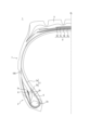
- FIG. 1 is a cross-sectional view in the tire width direction of a pneumatic tire according to one embodiment of the present invention.
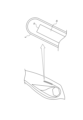
- FIG. 2 is an enlarged view of the periphery of a bead portion in FIG. 1 .
- FIG. 13 is a diagram illustrating a first modified example of the present embodiment.
- FIG. 13 is a diagram showing a second modified example of the present embodiment.
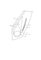
- 3 is a schematic view and an enlarged view of the vicinity of an end of a carcass ply.
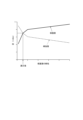
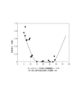
- FIG. FIG. 13 is a diagram showing the relationship between stiffness and distortion of a protective layer.
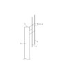
- 5A to 5C are schematic diagrams for explaining shear deformation due to the positional relationship between the cords of the reinforcing layer and the organic fiber cords.
- FIG. 11 is a diagram showing the relationship between the distance between the end of a carcass cord and the apex position of a turned-up portion of an organic fiber cord, and the crack speed near the end of the carcass cord.
- FIG. 1 is a diagram showing the relationship between the force at 5% elongation of an organic fiber cord and the length of a crack near the end or turn-back portion of the organic fiber cord.
- FIG. 1 is a diagram showing the physical properties of two types of organic fiber cords.
- FIG. 13 is a diagram showing the relationship between the overlap length between the reinforcing layer cord and the organic fiber cord and the length of the crack.
- FIG. 13 is a diagram illustrating a third modified example of the present embodiment.
- Figure 1 is a cross-sectional view in the tire width direction of a pneumatic tire (hereinafter, simply referred to as a tire) according to one embodiment of the present invention.
- Figure 1 shows only one half in the tire width direction bounded by the tire equatorial plane CL, but the other half has a similar configuration.
- Figure 1 shows a heavy-duty tire (a tire for trucks and buses) as an example, but the present invention can also be used for tires for a variety of other purposes, such as passenger car tires, aircraft tires, and mining tires.
- the internal structure of the tire is not particularly limited, but as an example, as shown in FIG. 1, the tire 1 has a carcass 3 that spans a pair of bead portions 2 in a toroidal shape, a belt 4 consisting of one or more belt layers that are arranged on the tire radial outside of the crown portion of the carcass 3, and a tread 5.
- a pair of sidewall portions 7 are connected between the pair of bead portions 2 and the tread 5.
- a bead core 2a is embedded in each of the pair of bead portions 2.
- a bead filler 2b with a generally triangular cross section is disposed on the radially outer side of the bead core 2a.
- the bead filler 2b can also be composed of a hard portion and a soft portion on the radially outer side of the hard portion.
- a wire chafer 6 is disposed around the bead core 2a (outer side of the carcass 3 when viewed from the bead core 2a).
- the carcass 3 is made of one or more carcass plies.
- the carcass ply is made of a carcass cord coated with rubber.
- the carcass cord can be, but is not limited to, a steel cord.
- the carcass 3 has a carcass main body 3a that spans a pair of bead portions 2 in a toroidal shape, and a carcass fold-back portion 3b that extends from the carcass main body 3a and folds back around the bead core 2a from the inside to the outside in the tire width direction.
- the end 3c of the carcass ply (the end of the carcass fold-back portion 3b) is located radially inward of the tire width direction.
- the belt 4 has four belt layers 4a to 4d.
- the belt layer 4a, the belt layer 4b, the belt layer 4c, and the belt layer 4d are arranged in this order from the inner side in the tire radial direction.
- the belt layer 4d has the smallest width in the tire width direction
- the belt layer 4b has the largest width in the tire width direction.
- the number of belt layers and the size of the width of the belt in the tire width direction can be variously configured.
- Each belt layer is made of a belt ply formed by rubber-coating belt cords.
- the belt cords are not particularly limited, but may be steel cords.
- the belt cords extend crossing each other between the layers.
- the inclination angle of the belt cords with respect to the tire circumferential direction may be 10° to 60°, and in heavy-duty tires, 15° to 60°, and preferably 30° to 60°.
- the tread 5 is made of tread rubber.
- the tread rubber can be configured, for example, as two or more layers laminated in the tire radial direction.
- the sidewall portion 7 is made of sidewall rubber.
- FIG. 2 is an enlarged view of the bead portion periphery in FIG. 1.
- a protective layer 8 consisting of a rubber-coated layer of organic fiber cords is arranged to cover the end 3c of the carcass ply.
- FIG. 5 is a schematic view and an enlarged view of the vicinity of the end 3c of the carcass ply.
- the protective layer 8 is U-shaped, that is, it extends from the inner side in the tire radial direction to the outer side on the inner side of the ply of the carcass folded-up portion 3b in the tire width direction, is folded back near the end 3c of the carcass ply, and extends from the outer side in the tire radial direction to the inner side on the outer side of the ply of the carcass folded-up portion 3b in the tire width direction, thereby covering the end 3c of the carcass ply and its vicinity.
- the organic fiber cords can be configured in a twill weave shape that crosses at approximately 90° within the tire. However, the configuration of the organic fiber cords is not limited to a twill weave shape.
- FIG. 3 is a diagram showing a first modified example of this embodiment.
- the protective layer 8 is arranged only on the outer side of the carcass ply in the tire width direction, and extends from the inner side to the outer side in the tire radial direction, beyond the end 3 c of the carcass ply in the tire radial direction.
- FIG. 4 is a diagram showing a second modified example of this embodiment.
- the protective layers 8 are arranged on the inner and outer sides of the carcass ply in the tire width direction, and each extends from the inner to the outer side in the tire radial direction to a position outside the end 3 c of the carcass ply in the tire radial direction.
- the protective layer 8 can cover the end 3c of the carcass ply in various manners on the outer side and/or the inner side in the tire width direction with respect to the carcass folded-up portion 3b.
- Figure 12 is a diagram showing a third modified example of this embodiment, and in this example, the protective layer 8 is U-shaped, that is, it extends from the radially inner side to the radially outer side of the tire on the tire widthwise inner side of the ply of the carcass folded-up portion 3b, is folded back radially outer than the end 3c of the carcass ply, and extends from the radially outer side to the inner side on the tire widthwise outer side of the ply of the carcass folded-up portion 3b, thereby covering the end 3c of the carcass ply and its vicinity.
- the diameter of the organic fiber cord is 0.04 to 0.60 mm.
- the organic fiber may be polyester, rayon, nylon, aramid, or the like.
- the organic fiber cord has the smallest diameter of all the cords that constitute the tire 1 (among all the tire constituent members present in any cross section in the tire width direction).
- the organic fiber cord extends radially outward from the end 3c of the carcass ply (in this example, the end of the carcass folded-back portion 3b).
- the protective layer 8 is folded back radially outward from the end of the carcass cord, thereby covering the end of the carcass cord.
- the pneumatic tire 1 of this embodiment includes a carcass 3 made of at least one carcass ply formed by rubber-coating carcass cords, and a protective layer 8 made of a rubber-coated layer of organic fiber cords is disposed to cover an end 3c of the carcass ply. This allows the protective layer 8 to protect the end 3c of the carcass ply, thereby making it possible to suppress failures occurring near the end of the carcass ply.
- the end 3c of the carcass ply is disposed relatively close to the rim flange portion, reducing the effect of the bending deformation described above, while the end of the organic fiber cord or the apex position of the folded-back portion of the organic fiber cord is relatively far from the rim flange portion, reducing the effect of the repeated deformation described above.
- the organic fiber cord has the smallest diameter among the cords constituting the tire 1, and therefore has low rigidity.
- the shortest distance between the end of the organic fiber cord or the apex position of the folded-back portion of the organic fiber cord and the end of the carcass ply is preferably 5 to 37 mm.
- Fig. 8 is a diagram showing the relationship between the distance between the end of the carcass cord and the apex position of the folded-back portion of the organic fiber cord, and the crack speed near the end of the carcass cord.
- a tire with a tire size of 275/80R22.5 was mounted on a rim with a rim size of 22.5 x 8.25J, the internal pressure was set to 875 kPa, the load was set to 57.33 kN, and the running distance was set to 30,000 km, and the crack length was calculated.
- the diameter of the organic fiber cord of the protective layer 8 is preferably 0.04 to 0.60 mm.
- FIG. 6 is a diagram showing the relationship between the rigidity of the protective layer and the strain (near the ends of the cords of the reinforcing layer and near the ends of the cords of the protective layer) (showing the results of predicted calculations). As shown in FIG. 6, the higher the rigidity of the protective layer 8, the smaller the strain near the ends of the carcass cords of the reinforcing layer (carcass in this embodiment) to be protected. On the other hand, if the rigidity of the protective layer 8 is high, the difference in rigidity with the rubber increases, so that the strain near the ends of the organic fiber cords of the protective layer 8 and near the folded portion in the example of FIG. 2 increases.
- the rigidity corresponding to the vicinity of the point where the larger strain between the strain near the ends of the cords of the reinforcing layer and the strain near the ends of the organic fiber cords of the protective layer is small can be set as the optimal rigidity value of the organic fiber cord, and the surrounding range can be set as the suitable rigidity range. Therefore, since the organic fiber cord has the smallest diameter among the cords constituting the pneumatic tire, distortion near the ends of the organic fiber cord in the protective layer 8 and near the folded-back portion in the example of Figure 2 can be suppressed, and the durability of the tire can be more reliably improved.
- the diameter of the organic fiber cord of the protective layer 8 it is possible to reduce distortion near the ends of the carcass cords to be protected, while on the other hand, by setting the diameter of the organic fiber cord of the protective layer 8 to 0.60 mm or less, it is possible to reduce distortion near the ends of the organic fiber cord of the protective layer 8 and near the folded-back portion in the example of Fig. 2. Therefore, by setting the diameter of the organic fiber cord of the protective layer 8 to 0.04 to 0.60 mm, it is possible to suppress in a balanced manner distortion near the ends of the carcass cords and distortion near the ends of the organic fiber cord of the protective layer 8 and near the folded-back portion in the example of Fig. 2, and more reliably suppress the occurrence and propagation of cracks.
- the force of the organic fiber cord at 5% elongation is preferably 2 to 10 N.
- Figure 9 is a diagram showing the relationship between the force of the organic fiber cord at 5% elongation and the crack length near the end or turn-back part of the organic fiber cord.
- the comparative example a tire using a protective layer made of organic fiber with a force of 41 N at elongation
- an index of "1" the smaller the index, the smaller the crack length
- the number of ends of the organic fiber cord is greater than the number of ends of the carcass cord, and that the gap between adjacent organic fiber cords is 0.1 mm or more.
- the number of ends of the organic fiber cord is greater than the number of ends of the carcass cord, it is possible to further suppress distortion near the ends of the carcass ply, while by making the gap between adjacent organic fiber cords 0.1 mm or more, it is possible to ensure a sufficient distance between the fibers, prevent the stress intensity factor from becoming large, and suppress the occurrence of cracks.
- the distance between the carcass cord and the organic fiber cord is preferably 0.2 to 1.0 mm.
- the distance is 0.2 mm or more.
- the overlap width between the carcass cord and the organic fiber cord is preferably 10 mm or more.
- FIG. 11 is a diagram showing the relationship between the overlap width between the cord of the reinforcing layer and the organic fiber cord and the crack length near the end of the reinforcing layer. As shown in FIG. 11, the effect was confirmed when the overlap width was 10 mm or more. On the other hand, although not particularly limited, the effect was saturated even when the overlap width was 17 mm or more, so from the viewpoint of reducing the number of parts and manufacturing variations, the overlap width is preferably 17 mm to 30 mm.
- the angle between the cords of the reinforcing layer and the organic fiber cords is 10° or less in the angle of the organic fiber cords in the two intersecting directions which has a larger number of cords per unit width, or the angle of the organic fiber cords in the two intersecting directions which has a smaller number of cords per unit width.
- the tire may be equipped with an RF tag as the communication device 100.
- the RF tag includes an IC chip and an antenna.
- the RF tag may be, for example, sandwiched between a plurality of the same or different members constituting the tire. In this way, the RF tag can be easily attached during tire production, and the productivity of tires equipped with an RF tag can be improved.
- the RF tag may be, for example, sandwiched between a bead filler and another member adjacent to the bead filler.
- the RF tag may be embedded in any of the members constituting the tire. In this way, the load applied to the RF tag can be reduced compared to when the RF tag is sandwiched between a plurality of members constituting the tire.
- the RF tag may be, for example, embedded in a rubber member such as a tread rubber or a side rubber. It is preferable that the RF tag is not placed at a position that is a boundary between members with different rigidity in the periphery length direction, which is a direction along the tire outer surface in a cross-sectional view in the tire width direction. In this way, the RF tag is not placed in a position where distortion is likely to concentrate due to a rigidity step. Therefore, the load applied to the RF tag can be reduced. This can improve the durability of the RF tag.
- the RF tag is not placed at a position that is, for example, a boundary between the end of the carcass and a member adjacent to the end of the carcass (e.g., a side rubber, etc.) in a cross-sectional view in the tire width direction.
- the number of RF tags is not particularly limited.
- a tire may include only one RF tag, or may include two or more RF tags.
- an RF tag is illustrated as an example of a communication device, but a communication device different from the RF tag may also be used.
- the RF tag may be placed, for example, in the tread portion of the tire. In this way, the RF tag is not damaged by a side cut of the tire.
- the RF tag may be placed, for example, in the center of the tread in the tire width direction.
- the center of the tread is a position in the tread portion where bending is unlikely to concentrate. In this way, the load applied to the RF tag can be reduced. This improves the durability of the RF tag.
- the RF tag may be placed, for example, within a range of 1/2 the tread width with the tire equatorial plane as the center in the tire width direction.
- the RF tag may be placed, for example, at the tread end in the tire width direction. If the position of the reader that communicates with the RF tag is predetermined, the RF tag may be placed, for example, at the tread end on one side closer to the reader. In this example, the RF tag may be placed, for example, within a range of 1/4 the tread width with the tread end as the outer end in the tire width direction.
- the RF tag may be arranged, for example, on the tire cavity side of the carcass, which includes one or more carcass plies that span between the bead portions. In this way, the RF tag is less likely to be damaged by impacts applied from outside the tire, or damage such as side cuts and nail penetration.
- the RF tag may be arranged in close contact with the surface of the carcass on the tire cavity side.
- the RF tag may be arranged, for example, between the carcass and another member located on the tire cavity side of the carcass.
- An example of another member located on the tire cavity side of the carcass is an inner liner that forms the tire inner surface.
- the RF tag may be attached to the tire inner surface facing the tire cavity.
- the RF tag By configuring the RF tag to be attached to the tire inner surface, it is easy to attach the RF tag to the tire and to inspect and replace the RF tag. In other words, the ease of attachment and maintenance of the RF tag can be improved.
- the RF tag by attaching the RF tag to the inner surface of the tire, the RF tag can be prevented from becoming the core of tire failure, compared to a configuration in which the RF tag is embedded in the tire.
- the RF tag may be positioned between the overlapped carcass plies.
- the RF tag may be arranged, for example, in the tread portion of the tire, on the tire radial outside of the belt including one or more belt plies.
- the RF tag may be arranged on the tire radial outside of the belt and in close contact with the belt.
- the RF tag may be arranged on the tire radial outside of the reinforcing belt layer and in close contact with the reinforcing belt layer.
- the RF tag may be embedded in the tread rubber on the tire radial outside of the belt.
- the RF tag By arranging the RF tag on the tire radial outside of the belt in the tread portion of the tire, communication with the RF tag from the outside of the tire in the tire radial direction is less likely to be hindered by the belt. Therefore, it is possible to improve communication with the RF tag from the outside of the tire in the tire radial direction.
- the RF tag may be arranged, for example, in the tire tread portion of the tire, on the tire radial inside of the belt. In this way, the tire radial outside of the RF tag is covered by the belt, so that the RF tag is less likely to be damaged by impacts from the tread surface or nail penetration.
- the RF tag may be placed in the tread portion of the tire, between the belt and the carcass located radially inward of the belt. Also, if the belt has multiple belt plies, the RF tag may be placed in the tread portion of the tire, between any two belt plies. In this way, the outer side of the RF tag in the tire radial direction is covered by one or more belt plies, making the RF tag less susceptible to damage from impacts from the tread surface or nail penetration.
- the RF tag may be arranged, for example, sandwiched between the cushion rubber and the tread rubber, or between the cushion rubber and the side rubber. In this way, the impact on the RF tag can be mitigated by the cushion rubber. This improves the durability of the RF tag.
- the RF tag may also be embedded, for example, in the cushion rubber.
- the cushion rubber may be made up of multiple adjacent rubber members of the same or different types. In such cases, the RF tag may be arranged, sandwiched between the multiple rubber members that make up the cushion rubber.
- the RF tag may be arranged, for example, at the sidewall or bead of the tire.
- the RF tag may be arranged, for example, at one sidewall or one bead that is closer to a reader that can communicate with the RF tag. In this way, the communication between the RF tag and the reader can be improved.
- the RF tag may be arranged between the carcass and the side rubber, or between the tread rubber and the side rubber.
- the RF tag may be arranged, for example, in the tire radial direction, between the position where the tire is at its maximum width and the position of the tread surface.
- the communication with the RF tag from the outside of the tire in the tire radial direction can be improved compared to a configuration in which the RF tag is arranged on the inner side in the tire radial direction from the position where the tire is at its maximum width.
- the RF tag may be arranged, for example, on the inner side in the tire radial direction from the position where the tire is at its maximum width. In this way, the RF tag is arranged near the bead portion that has high rigidity. Therefore, the load applied to the RF tag can be reduced. This can improve the durability of the RF tag.
- the RF tag may be arranged at a position adjacent to the bead core in the tire radial direction or tire width direction.
- Distortion is less likely to concentrate near the bead core. This reduces the load on the RF tag. This improves the durability of the RF tag.
- the RF tag is placed radially inward from the maximum tire width position and radially outward from the bead core of the bead portion. This improves the durability of the RF tag, and communication between the RF tag and the reader is less likely to be hindered by the bead core, improving the communication performance of the RF tag.
- the RF tag may be sandwiched between the multiple rubber members that make up the side rubber.
- the RF tag may be sandwiched between the bead filler and a member adjacent to the bead filler. In this way, the RF tag can be placed in a position where distortion is less likely to concentrate due to the placement of the bead filler. Therefore, the load on the RF tag can be reduced. This improves the durability of the RF tag.
- the RF tag may be sandwiched between the bead filler and the carcass, for example.
- the portion of the carcass that sandwiches the RF tag together with the bead filler may be located on the outer side of the bead filler in the tire width direction, or may be located on the inner side of the tire width direction.
- the bead filler may also have a portion that is located adjacent to the side rubber. In such a case, the RF tag may be disposed by being sandwiched between the bead filler and the side rubber. Furthermore, the bead filler may have a portion disposed adjacent to the rubber chafer. In such a case, the RF tag may be disposed by being sandwiched between the bead filler and the rubber chafer.
- the RF tag may be sandwiched between the stiffener and a member adjacent to the stiffener. In this way, the RF tag can be placed in a position where the stiffener makes it difficult for distortion to concentrate. Therefore, the load on the RF tag can be reduced. This improves the durability of the RF tag.
- the RF tag may be sandwiched between the stiffener and the side rubber, for example.
- the RF tag may also be sandwiched between the stiffener and the carcass, for example.
- the part of the carcass that sandwiches the RF tag together with the stiffener may be located on the outside in the tire width direction relative to the stiffener, or may be located on the inside in the tire width direction.
- the stiffener may have a part that is located adjacent to the rubber chafer. In this case, the RF tag may be sandwiched between the stiffener and the rubber chafer. The stiffener may have a portion adjacent to the hat rubber on the outer side in the tire width direction. In this case, the RF tag may be sandwiched between the stiffener and the hat rubber.
- the stiffener may be composed of a plurality of rubber members having different hardness.
- the RF tag may be sandwiched between a plurality of rubber members constituting the stiffener.
- the RF tag may be sandwiched between the hat rubber and a member adjacent to the hat rubber.
- the RF tag may be sandwiched between, for example, the hat rubber and the carcass ply. In this way, the impact on the RF tag can be mitigated by the hat rubber. Therefore, the durability of the RF tag can be improved.
- the RF tag may be arranged, for example, sandwiched between the rubber chafer and the side rubber. In this way, the RF tag can be arranged in a position where distortion is less likely to be concentrated due to the placement of the rubber chafer. This makes it possible to reduce the load on the RF tag. This makes it possible to improve the durability of the RF tag.
- the RF tag may be arranged, for example, sandwiched between the rubber chafer and the carcass. In this way, it makes it possible to reduce the load on the RF tag due to impacts and damage from the rim. This makes it possible to improve the durability of the RF tag.
- the RF tag may be sandwiched between the nylon chafer and another member adjacent to the nylon chafer on the outer or inner side in the tire width direction. In this way, the position of the RF tag is less likely to fluctuate when the tire deforms. Therefore, the load applied to the RF tag when the tire deforms can be reduced. This improves the durability of the RF tag.
- the nylon chafer may have a portion adjacent to the rubber chafer, for example, on the outer side in the tire width direction. In such a case, the RF tag may be sandwiched between the nylon chafer and the rubber chafer.
- the nylon chafer may have a portion adjacent to the side rubber, for example, on the outer side in the tire width direction.
- the RF tag may be sandwiched between the nylon chafer and the side rubber.
- the nylon chafer may have a portion adjacent to the stiffener, for example, on the inner side in the tire width direction.
- the RF tag may be sandwiched between the nylon chafer and the stiffener.
- the nylon chafer may have a portion adjacent to the hat rubber, for example, on the inner side in the tire width direction.
- the RF tag may be disposed by being sandwiched between the nylon chafer and the hat rubber.
- the nylon chafer may have a portion adjacent to the carcass, for example, on the inner side in the tire width direction.
- the RF tag may be disposed by being sandwiched between the nylon chafer and the carcass.
- the nylon chafer may have a portion adjacent to the wire chafer, for example, on the inner side in the tire width direction.
- the RF tag may be disposed by being sandwiched between the nylon chafer and the wire chafer. In this way, the RF tag may be disposed by being sandwiched between the nylon chafer and another member adjacent to the outer side or inner side of the nylon chafer in the tire width direction.
- the load applied to the RF tag due to impact or damage from the outside of the tire in the tire width direction can be further reduced. This can further improve the durability of the RF tag.
- the RF tag may be sandwiched between the wire chafer and another adjacent member on the inside or outside of the wire chafer in the tire width direction. This makes it difficult for the position of the RF tag to fluctuate when the tire deforms. This reduces the load applied to the RF tag when the tire deforms. This improves the durability of the RF tag.
- the other member adjacent to the wire chafer on the inside or outside of the tire width direction may be, for example, a rubber member such as a rubber chafer.
- the other member adjacent to the wire chafer on the inside or outside of the tire width direction may be, for example, a carcass.
- a belt reinforcing layer may be further provided on the radially outer side of the belt.
- the belt reinforcing layer may be formed by winding a cord made of polyethylene terephthalate continuously in a spiral shape in the tire circumferential direction.
- the cord may be subjected to an adhesive treatment under a tension of 6.9 ⁇ 10 ⁇ 2 N/tex or more, and may have an elastic modulus of 2.5 mN/dtex ⁇ % or more at a load of 29.4 N measured at 160° C.
- the belt reinforcing layer may be arranged so as to cover the entire belt or only both ends of the belt.
- the winding density per unit width of the belt reinforcing layer may differ depending on the position in the width direction. In this way, road noise and flat spots can be reduced without reducing high-speed durability.
- a sample tire was produced and its tire life was evaluated by an indoor durability test.
- Each tire was provided with a protective layer made of a rubberized layer of organic fiber cords covering the end of at least one carcass ply made of rubber-coated carcass cords.
- the specifications of each tire are shown in Table 1 below along with the evaluation results.
- the tire size was 275/80R22.5
- the load was 37.19kN
- the mileage was 100,000km
- the internal pressure was 900kPa
- the rim was 22.5x7.5J.
- a tire was produced using a protective layer made of organic fiber with an elongation force of 41N, and the evaluation results are shown as an index with "1" as the index.
- SDGs Sustainable Development Goals
Landscapes
- Engineering & Computer Science (AREA)
- Mechanical Engineering (AREA)
- Tires In General (AREA)
Abstract
Description
(1)カーカスコードをゴム被覆してなる少なくとも1枚のカーカスプライからなるカーカスを備えた、空気入りタイヤであって、
前記カーカスプライの端を覆う、有機繊維コードのゴム引き層からなる保護層が配置され、
前記有機繊維コードは、前記空気入りタイヤの構成部材のコードの中で最も小さい径を有しており、
前記有機繊維コードの少なくとも一部は、前記カーカスプライの端よりもタイヤ径方向外側まで延在することを特徴とする、空気入りタイヤ。
ここで、「有機繊維コードの5%伸長時の力」は、空気入りタイヤから前記保護層を取り出し、その中から1本の有機繊維コードを取り出し、当該1本の有機繊維コードを5%伸ばした際にかかる力を計測して求めるものとする(JISL1095:2010年に準拠)。
ここで、「距離」は、タイヤ幅方向断面において、補強層のコードの延在方向に直交する方向に計測した際の、補強層のコードと有機繊維コードとの最短距離をいうものとする。
ここで、「適用リム」とは、タイヤが生産され、使用される地域に有効な産業規格であって、日本ではJATMA(日本自動車タイヤ協会)のJATMA YEAR BOOK、欧州ではETRTO(The European Tyre and Rim Technical Organisation)のSTANDARDS MANUAL、米国ではTRA(The Tire and Rim Association,Inc.)のYEAR BOOK等に記載されているまたは将来的に記載される、適用サイズにおける標準リム(ETRTOのSTANDARDS MANUALではMeasuring Rim、TRAのYEAR BOOKではDesign Rim)を指す(即ち、上記の「リム」には、現行サイズに加えて将来的に上記産業規格に含まれ得るサイズも含む。「将来的に記載されるサイズ」の例としては、ETRTO 2013年度版において「FUTURE DEVELOPMENTS」として記載されているサイズを挙げることができる。)が、上記産業規格に記載のないサイズの場合は、タイヤのビード幅に対応した幅のリムをいう。また、「規定内圧」とは、上記JATMA等に記載されている、適用サイズ・プライレーティングにおける単輪の最大負荷能力に対応する空気圧(最高空気圧)を指し、上記産業規格に記載のないサイズの場合は、「規定内圧」は、タイヤを装着する車両毎に規定される最大負荷能力に対応する空気圧(最高空気圧)をいうものとする。
また、各ベルト層は、ベルトコードをゴム被覆してなるベルトプライからなる。ベルトコードは、特には限定されないが、スチールコードとすることができる。ベルトコードは、層間で互いに交差して延びている。特には限定されないが、ベルトコードのタイヤ周方向に対する傾斜角度は、10°~60°、重荷重用タイヤでは15°~60°、好ましくは30°~60°とすることができる。
図4は、本実施形態の第2の変形例を示す図であり、この例では、保護層8は、カーカスプライのタイヤ幅方向内側及び外側のそれぞれに配置され、各々が、タイヤ径方向内側から外側へと、カーカスプライの端3cよりもタイヤ径方向外側まで延びている。
このように、保護層8は、カーカス折り返し部3bに対してタイヤ幅方向外側及び/又は内側において、カーカスプライの端3cを様々な態様で覆うことができる。
図12は、本実施形態の第3の変形例を示す図であり、この例では、保護層8は、Uの字の形状であり、すなわち、カーカス折り返し部3bのプライのタイヤ幅方向内側においてタイヤ径方向内側から外側に向かって延び、カーカスプライの端3cよりもタイヤ径方向外側で折り返されて、カーカス折り返し部3bのプライのタイヤ幅方向外側においてタイヤ径方向外側から内側に向かって延び、これにより、カーカスプライの端3c及びその付近を覆っている。
以下、本実施形態の空気入りタイヤの作用効果について説明する。
ここで、カーカスプライの端や有機繊維コードの端又は有機繊維コードの折り返し部の頂点位置が、ビード部2のリムフランジ部に近づくほど、タイヤ転動時に、リムフランジ部とカーカスプライの折り返し部3bとに挟まれたゴムがタイヤ径方向外側に移動する変形が繰り返されることにより、カーカスプライの端や有機繊維コードの端や有機繊維コードの折り返し部の頂点位置付近の歪みが大きくなり、十分なタイヤ寿命が得られなくなる懸念がある。一方で、よりタイヤ径方向外側の領域では、タイヤ転動時のビード部2の接地域での曲げ変形が大きくなり、カーカスプライの端や有機繊維コードの端や有機繊維コードの折り返し部の頂点位置付近の歪みが大きくなる。
これに対し、本実施形態の空気入りタイヤ1では、有機繊維コードの少なくとも一部は、カーカスプライの端(本例では、カーカス折り返し部3bの端)3cよりもタイヤ径方向外側まで延在している。これにより、カーカスプライの端3cは、相対的にリムフランジ部に近づけて配置し、上記の曲げ変形の影響を低減しつつも、有機繊維コードの端又は有機繊維コードの折り返し部の頂点位置を相対的にリムフランジ部から遠ざけて、上記の繰り返し変形の影響を低減することができる。ここで、有機繊維コードは、タイヤ1の構成部材のコードの中で最も小さい径を有しているため、剛性が低く、上記のような配置とすることで、歪み集中を低減することによる亀裂の発生の抑制効果を有効に得ることができる。
以上のように、本実施形態の空気入りタイヤによれば、耐久性を向上させることができる。
図8は、カーカスコードの端と有機繊維コードの折り返し部の頂点位置との距離と、カーカスコードの端付近での亀裂速度との関係を示す図である。タイヤサイズ275/80R22.5のタイヤを、リムサイズ22.5×8.25Jのリムに組み付け、内圧を875kPaとし、荷重57.33kNで、走行距離30,000kmとし、亀裂長さを求めた。上記最短距離を5~37mmとすることにより、およそ10%の寿命向上が見込めた。
これは、上記最短距離を5mm以上37mm以下とすることにより、カーカスプライの端3cを相対的にリムフランジ部に近づけつつも、有機繊維コードの端又は有機繊維コードの折り返し部の頂点位置を相対的にリムフランジ部から遠ざけて、上記の効果を有効に得ることができるためであると考えられる。
特に、保護層8の有機繊維コードの径を0.04mm以上とすることにより、保護されるカーカスコードの端付近の歪みを低減することができ、一方で、保護層8の有機繊維コードの径を0.60mm以下とすることにより、保護層8の有機繊維コードの端付近や図2の例での折り返し部付近での歪みを低減することができる。従って、保護層8の有機繊維コードの径は、0.04~0.60mmとすることにより、カーカスコードの端付近の歪みと、保護層8の有機繊維コードの端付近や図2の例での折れ曲がり部付近での歪みをバランス良く抑制して、亀裂の発生や進展をより確実に抑制することができる。
そこで、上記基準状態において、カーカスコードと有機繊維コードとの距離は、0.2~1.0mmであることが好ましい。上記距離を1.0mm以下とすることにより、せん断変形を小さくして、タイヤの耐久性をさらに向上させ得るからである。一方で、特には限定されないものの、製造上の観点から、上記距離は0.2mm以上とすることが好ましい。なお、上記距離を1.0mmとした場合に、伸長時の力が41Nの有機繊維から成る保護層を用いたタイヤ対比で、タイヤの室内試験結果で10%のタイヤ寿命の向上が確認できた。
また、製造上の観点からは、補強層のコードと有機繊維コードとのなす角度は、交差する2方向の有機繊維コードのうち単位幅当たりのコード数が多い方、又は、2方向の有機繊維コードのうち小さい方の角度が10°以下であることが好ましい。

持続可能な社会の実現に向けて、SDGsが提唱されている。本発明の一実施形態は「No.12_つくる責任、つかう責任」および「No.13_気候変動に具体的な対策を」などに貢献する技術となり得ると考えられる。
5:トレッド、 6:ワイヤーチェーファー、 7:サイドウォール部、
8:保護層、 100:通信装置、 CL:タイヤ赤道面
Claims (8)
- カーカスコードをゴム被覆してなる少なくとも1枚のカーカスプライからなるカーカスを備えた、空気入りタイヤであって、
前記カーカスプライの端を覆う、有機繊維コードのゴム引き層からなる保護層が配置され、
前記有機繊維コードは、前記空気入りタイヤの構成部材のコードの中で最も小さい径を有しており、
前記有機繊維コードの少なくとも一部は、前記カーカスプライの端よりもタイヤ径方向外側まで延在することを特徴とする、空気入りタイヤ。 - 一対のビード部をさらに備え、
前記カーカスは、前記一対のビード部間をトロイダル状に跨るカーカス本体部と、前記カーカス本体部から延びて前記ビードコアの周りを折り返されてなるカーカス折り返し部と、を有し、
前記有機繊維コードの少なくとも一部は、前記カーカス折り返し部の端よりもタイヤ径方向外側まで延在する、請求項1に記載の空気入りタイヤ。 - 前記有機繊維コードの端又は前記有機繊維コードの折り返し部の頂点位置と、前記カーカスプライの端との最短距離は、5~37mmである、請求項1又は2に記載の空気入りタイヤ。
- 前記有機繊維コードの5%伸長時の歪みは、2~10Nである、請求項1~3のいずれか一項に記載の空気入りタイヤ。
- 前記有機繊維コードの打ち込み数は、前記カーカスコードの打ち込み数より多く、且つ、隣接する前記有機繊維コード間の間隙は、0.1mm以上である、請求項1~4のいずれか一項に記載の空気入りタイヤ。
- 前記空気入りタイヤを適用リムに装着し、規定内圧を充填し、無負荷とした、基準状態において、
前記カーカスコードと前記有機繊維コードとの距離は、0.2~1.0mmである、請求項1~5のいずれか一項に記載の空気入りタイヤ。 - 前記空気入りタイヤを適用リムに装着し、規定内圧を充填し、無負荷とした、基準状態において、
前記カーカスコードと前記有機繊維コードとの重なり幅は、10mm以上である、請求項1~6のいずれか一項に記載の空気入りタイヤ。 - 前記保護層は、前記カーカスコードの端よりもタイヤ径方向外側で折り返されることにより、前記カーカスコードの端を覆っている、請求項1~7のいずれか一項に記載の空気入りタイヤ。
Priority Applications (2)
| Application Number | Priority Date | Filing Date | Title |
|---|---|---|---|
| EP23900229.8A EP4631743A4 (en) | 2022-12-06 | 2023-07-27 | Pneumatic tire |
| CN202380081143.7A CN120265472A (zh) | 2022-12-06 | 2023-07-27 | 充气轮胎 |
Applications Claiming Priority (2)
| Application Number | Priority Date | Filing Date | Title |
|---|---|---|---|
| JP2022-195176 | 2022-12-06 | ||
| JP2022195176A JP2024081505A (ja) | 2022-12-06 | 2022-12-06 | 空気入りタイヤ |
Publications (1)
| Publication Number | Publication Date |
|---|---|
| WO2024122100A1 true WO2024122100A1 (ja) | 2024-06-13 |
Family
ID=91379123
Family Applications (1)
| Application Number | Title | Priority Date | Filing Date |
|---|---|---|---|
| PCT/JP2023/027666 Ceased WO2024122100A1 (ja) | 2022-12-06 | 2023-07-27 | 空気入りタイヤ |
Country Status (4)
| Country | Link |
|---|---|
| EP (1) | EP4631743A4 (ja) |
| JP (1) | JP2024081505A (ja) |
| CN (1) | CN120265472A (ja) |
| WO (1) | WO2024122100A1 (ja) |
Citations (5)
| Publication number | Priority date | Publication date | Assignee | Title |
|---|---|---|---|---|
| JPH0840025A (ja) * | 1994-01-01 | 1996-02-13 | Sumitomo Rubber Ind Ltd | 重荷重用空気入りラジアルタイヤ及びその製造方法 |
| JP2003306009A (ja) * | 2002-04-17 | 2003-10-28 | Bridgestone Corp | 空気入りタイヤ |
| JP2004314886A (ja) * | 2003-04-18 | 2004-11-11 | Bridgestone Corp | ゴム補強体及びそれを用いた空気入りタイヤ |
| JP2005145318A (ja) * | 2003-11-18 | 2005-06-09 | Bridgestone Corp | 空気入りラジアルタイヤ |
| JP2005205946A (ja) * | 2004-01-20 | 2005-08-04 | Yokohama Rubber Co Ltd:The | 空気入りラジアルタイヤ |
Family Cites Families (4)
| Publication number | Priority date | Publication date | Assignee | Title |
|---|---|---|---|---|
| JPH0199702U (ja) | 1987-12-25 | 1989-07-04 | ||
| JP2006199087A (ja) * | 2005-01-19 | 2006-08-03 | Bridgestone Corp | 空気入りタイヤ及びその製造方法 |
| JP2012245655A (ja) * | 2011-05-25 | 2012-12-13 | Bridgestone Corp | 空気入りタイヤの製造方法および空気入りタイヤ |
| JP6989374B2 (ja) * | 2017-12-22 | 2022-01-05 | Toyo Tire株式会社 | 重荷重用空気入りラジアルタイヤ |
-
2022
- 2022-12-06 JP JP2022195176A patent/JP2024081505A/ja active Pending
-
2023
- 2023-07-27 CN CN202380081143.7A patent/CN120265472A/zh active Pending
- 2023-07-27 EP EP23900229.8A patent/EP4631743A4/en active Pending
- 2023-07-27 WO PCT/JP2023/027666 patent/WO2024122100A1/ja not_active Ceased
Patent Citations (5)
| Publication number | Priority date | Publication date | Assignee | Title |
|---|---|---|---|---|
| JPH0840025A (ja) * | 1994-01-01 | 1996-02-13 | Sumitomo Rubber Ind Ltd | 重荷重用空気入りラジアルタイヤ及びその製造方法 |
| JP2003306009A (ja) * | 2002-04-17 | 2003-10-28 | Bridgestone Corp | 空気入りタイヤ |
| JP2004314886A (ja) * | 2003-04-18 | 2004-11-11 | Bridgestone Corp | ゴム補強体及びそれを用いた空気入りタイヤ |
| JP2005145318A (ja) * | 2003-11-18 | 2005-06-09 | Bridgestone Corp | 空気入りラジアルタイヤ |
| JP2005205946A (ja) * | 2004-01-20 | 2005-08-04 | Yokohama Rubber Co Ltd:The | 空気入りラジアルタイヤ |
Non-Patent Citations (2)
| Title |
|---|
| "ETRTO", 2013, article "FUTURE DEVELOPMENTS" |
| See also references of EP4631743A1 |
Also Published As
| Publication number | Publication date |
|---|---|
| EP4631743A4 (en) | 2026-03-25 |
| CN120265472A (zh) | 2025-07-04 |
| EP4631743A1 (en) | 2025-10-15 |
| JP2024081505A (ja) | 2024-06-18 |
Similar Documents
| Publication | Publication Date | Title |
|---|---|---|
| JP7379979B2 (ja) | 重荷重用空気入りタイヤ | |
| CN103764411B (zh) | 充气轮胎 | |
| EP2818332B1 (en) | Pneumatic tire | |
| US20110126956A1 (en) | Pneumatic tire | |
| US11254167B2 (en) | Pneumatic tyre | |
| EP2853419B1 (en) | Pneumatic tire | |
| EP4656411A1 (en) | Tire for passenger car | |
| EP4212364B1 (en) | Heavy duty pneumatic tire | |
| US20230382162A1 (en) | Tire | |
| WO2024185192A1 (ja) | 空気入りタイヤ | |
| WO2024122100A1 (ja) | 空気入りタイヤ | |
| WO2024122098A1 (ja) | 空気入りタイヤ | |
| WO2024122099A1 (ja) | 空気入りタイヤ | |
| WO2024122097A1 (ja) | 空気入りタイヤ | |
| EP3536522B1 (en) | Run flat tire | |
| JP7818488B2 (ja) | 乗用車用空気入りラジアルタイヤ | |
| JP7672287B2 (ja) | 航空機用ラジアルタイヤ | |
| JP5917989B2 (ja) | 空気入りタイヤ | |
| WO2025120886A1 (ja) | 重荷重用タイヤ | |
| WO2025120885A1 (ja) | 重荷重用タイヤ | |
| WO2024034225A1 (ja) | 乗用車用空気入りラジアルタイヤ | |
| JP2026070316A (ja) | 空気入りタイヤ | |
| WO2024034226A1 (ja) | 乗用車用空気入りラジアルタイヤ | |
| JP2026070317A (ja) | 空気入りタイヤ |
Legal Events
| Date | Code | Title | Description |
|---|---|---|---|
| 121 | Ep: the epo has been informed by wipo that ep was designated in this application |
Ref document number: 23900229 Country of ref document: EP Kind code of ref document: A1 |
|
| WWE | Wipo information: entry into national phase |
Ref document number: 202380081143.7 Country of ref document: CN |
|
| WWP | Wipo information: published in national office |
Ref document number: 202380081143.7 Country of ref document: CN |
|
| WWE | Wipo information: entry into national phase |
Ref document number: 2023900229 Country of ref document: EP |
|
| NENP | Non-entry into the national phase |
Ref country code: DE |
|
| ENP | Entry into the national phase |
Ref document number: 2023900229 Country of ref document: EP Effective date: 20250707 |
|
| WWP | Wipo information: published in national office |
Ref document number: 2023900229 Country of ref document: EP |