WO2024122273A1 - 復号装置、符号化装置、復号方法、及び符号化方法 - Google Patents
復号装置、符号化装置、復号方法、及び符号化方法 Download PDFInfo
- Publication number
- WO2024122273A1 WO2024122273A1 PCT/JP2023/040738 JP2023040738W WO2024122273A1 WO 2024122273 A1 WO2024122273 A1 WO 2024122273A1 JP 2023040738 W JP2023040738 W JP 2023040738W WO 2024122273 A1 WO2024122273 A1 WO 2024122273A1
- Authority
- WO
- WIPO (PCT)
- Prior art keywords
- information
- real space
- detection information
- image
- mobile device
- Prior art date
- Legal status (The legal status is an assumption and is not a legal conclusion. Google has not performed a legal analysis and makes no representation as to the accuracy of the status listed.)
- Ceased
Links
Images









Classifications
-
- G—PHYSICS
- G06—COMPUTING OR CALCULATING; COUNTING
- G06V—IMAGE OR VIDEO RECOGNITION OR UNDERSTANDING
- G06V20/00—Scenes; Scene-specific elements
- G06V20/50—Context or environment of the image
- G06V20/56—Context or environment of the image exterior to a vehicle by using sensors mounted on the vehicle
- G06V20/58—Recognition of moving objects or obstacles, e.g. vehicles or pedestrians; Recognition of traffic objects, e.g. traffic signs, traffic lights or roads
-
- G—PHYSICS
- G06—COMPUTING OR CALCULATING; COUNTING
- G06T—IMAGE DATA PROCESSING OR GENERATION, IN GENERAL
- G06T7/00—Image analysis
- G06T7/20—Analysis of motion
-
- G—PHYSICS
- G06—COMPUTING OR CALCULATING; COUNTING
- G06T—IMAGE DATA PROCESSING OR GENERATION, IN GENERAL
- G06T7/00—Image analysis
- G06T7/70—Determining position or orientation of objects or cameras
-
- H—ELECTRICITY
- H04—ELECTRIC COMMUNICATION TECHNIQUE
- H04N—PICTORIAL COMMUNICATION, e.g. TELEVISION
- H04N19/00—Methods or arrangements for coding, decoding, compressing or decompressing digital video signals
- H04N19/10—Methods or arrangements for coding, decoding, compressing or decompressing digital video signals using adaptive coding
- H04N19/169—Methods or arrangements for coding, decoding, compressing or decompressing digital video signals using adaptive coding characterised by the coding unit, i.e. the structural portion or semantic portion of the video signal being the object or the subject of the adaptive coding
- H04N19/184—Methods or arrangements for coding, decoding, compressing or decompressing digital video signals using adaptive coding characterised by the coding unit, i.e. the structural portion or semantic portion of the video signal being the object or the subject of the adaptive coding the unit being bits, e.g. of the compressed video stream
-
- H—ELECTRICITY
- H04—ELECTRIC COMMUNICATION TECHNIQUE
- H04N—PICTORIAL COMMUNICATION, e.g. TELEVISION
- H04N19/00—Methods or arrangements for coding, decoding, compressing or decompressing digital video signals
- H04N19/20—Methods or arrangements for coding, decoding, compressing or decompressing digital video signals using video object coding
-
- H—ELECTRICITY
- H04—ELECTRIC COMMUNICATION TECHNIQUE
- H04N—PICTORIAL COMMUNICATION, e.g. TELEVISION
- H04N19/00—Methods or arrangements for coding, decoding, compressing or decompressing digital video signals
- H04N19/70—Methods or arrangements for coding, decoding, compressing or decompressing digital video signals characterised by syntax aspects related to video coding, e.g. related to compression standards
Definitions
- This disclosure relates to a decoding device, an encoding device, a decoding method, and an encoding method.
- Patent Document 1 discloses an autonomous vehicle equipped with an object detection unit and an autonomous module.
- the object detection unit measures the detection distance using a camera or the like.
- the autonomous module determines a control range limited within the detection distance, and reflects the learned driving tendencies of the user and driving tendencies defined by external data in the vehicle's driving control-related data.
- the present disclosure aims to effectively utilize detection information regarding objects present around an autonomous driving device, thereby improving the safety of the autonomous driving device, such as its collision avoidance performance.
- a decoding device includes a circuit and a memory connected to the circuit, and the circuit receives a bitstream from an autonomous driving device having a photographing unit, decodes an image captured by the photographing unit from the bitstream, decodes intra-image detection information, which is detection information within the image relating to an object included in the image, from the bitstream, and decodes real-space detection information, which is detection information in real space relating to the object, from the bitstream.
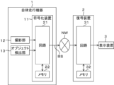
- FIG. 1 is a diagram showing a simplified configuration of an information processing system according to a first embodiment of the present disclosure.
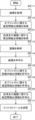
- 13 is a flowchart showing the flow of processing executed by a circuit of the encoding device.
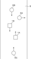
- FIG. 2 is a diagram illustrating an example of a traveling situation of an autonomous traveling device.
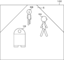
- FIG. 2 is a diagram illustrating an example of an image captured by a capturing section.
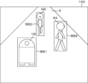
- FIG. 10 is a diagram illustrating an example of an image analysis result.
- 1A and 1B are diagrams illustrating simplified examples of real space detection information and in-image detection information related to an object.
- FIG. 2 is a diagram illustrating an example of a coordinate system of an autonomous driving device.
- FIG. 2 is a simplified diagram showing the data structure of a bitstream.
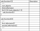
- FIG. 13 is a simplified diagram illustrating an example of syntax.
- 13 is a flowchart showing the flow of processing executed by a circuit of the decoding device.
- FIG. 13 is a diagram showing a simplified example of a display image.
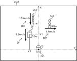
- FIG. 13 is a diagram showing a simplified example of a display image.
- FIG. 13 is a diagram showing a simplified example of a display image.
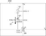
- FIG. 14 is a diagram showing some figures extracted from the display image shown in FIG. 13 .
- FIG. 13 is a diagram showing a simplified example of a display image.
- FIG. 13 is a diagram showing a simplified configuration of an information processing system according to a modified example.
- 13 is a flowchart showing the flow of processing executed by a circuit of the encoding device.
- FIG. 13 is a diagram showing a simplified example of a display image.
- FIG. 13 is a diagram showing a simplified example of a display image.
- FIG. 13 is a diagram showing a simplified configuration of an information processing
- FIG. 13 is a simplified diagram illustrating an example of syntax.
- 13 is a flowchart showing the flow of processing executed by a circuit of the decoding device.
- FIG. 13 is a diagram showing a simplified example of a display image.
- FIG. 13 is a diagram showing a simplified example of a display image.
- FIG. 11 is a diagram showing a simplified configuration of an information processing system according to a second embodiment of the present disclosure.
- 13 is a flowchart showing the flow of processing executed by a circuit of the decoding device.
- FIG. 2 is a diagram illustrating an example of an image captured by a capturing section.
- FIG. 2 is a diagram showing a simplified example of a map.
- the unmanned autonomous driving devices travel on sidewalks at the same speed as pedestrians to deliver products.
- the autonomous driving devices are equipped with cameras, GPS receivers, obstacle sensors, etc., which complement each other in order to ensure safe driving.
- the autonomous driving devices transmit images captured by their own cameras in real time to a monitoring center where an operator is always present.
- the inventors discovered that the above problems could be solved by transmitting, from the autonomous mobile device to a monitoring center, and effectively utilizing, not only images captured by a camera, but also detection information in real space detected by sensors mounted on the autonomous mobile device, and came up with the present disclosure.
- the decoding device includes a circuit and a memory connected to the circuit, and the circuit receives a bitstream from an autonomous driving device having a photographing unit, decodes an image captured by the photographing unit from the bitstream, decodes intra-image detection information, which is detection information within the image relating to an object included in the image, from the bitstream, and decodes real-space detection information, which is detection information in real space relating to the object, from the bitstream.
- the decoding device can effectively utilize on-screen detection information and real-space detection information regarding objects present around the autonomous driving device, thereby improving the safety of the autonomous driving device, such as collision avoidance performance.
- the in-image detection information regarding the object may include position information of the object within the image.
- the position information of objects within an image can be effectively utilized on the decoding device side.
- the real space detection information regarding the object may include at least one of position information of the object in the real space and movement information of the object in the real space.
- the position information and movement information of the object in the real space can be effectively utilized on the decoding device side.
- the position information of the object may include coordinate values in a circular coordinate system based on the autonomous mobile device, coordinate values in a Cartesian coordinate system based on the autonomous mobile device, or coordinate values in a geographic coordinate system.
- the position of an object can be accurately identified using position information including coordinate values.
- the movement information of the object may include at least one of the absolute speed of the object or the relative speed of the object with respect to the autonomous mobile device, and the absolute movement direction of the object or the relative movement direction of the object with respect to the autonomous mobile device.
- At least one of the speed and the moving direction of an object can be accurately determined by movement information including at least one of absolute speed or relative speed and absolute moving direction or relative moving direction.
- the circuit further decodes real-space detection information related to the autonomous driving device from the bit stream, and the real-space detection information related to the autonomous driving device may include position information of the autonomous driving device in the real space and movement information of the autonomous driving device in the real space.
- the position information and movement information of the autonomous mobile device in the real space can be effectively utilized on the decoding device side.
- the location information of the autonomous mobile device may include coordinate values in a geographic coordinate system.
- the absolute position of the autonomous driving device can be accurately determined by using position information including coordinate values in a geographic coordinate system.
- the movement information of the autonomous mobile device may include at least one of the absolute speed and absolute movement direction of the autonomous mobile device.
- At least one of the absolute speed and absolute movement direction of the autonomous mobile device can be accurately determined using the movement information.
- the circuit may decode the in-image detection information and the real-space detection information relating to the object, and the real-space detection information relating to the autonomous driving device from the SEI region of the bitstream.
- the in-image detection information and real-space detection information related to the object and the real-space detection information related to the autonomous driving device are encoded in the SEI area of the bitstream, allowing for easy processing on the decoding device side.
- the circuit may further generate a display image for human vision, and the display image may include the object and at least one of position information for displaying the object in the real space and movement information for displaying the object in the real space.
- an operator can instantly and accurately grasp the situation around the autonomous mobile device.
- the autonomous driving device includes a plurality of autonomous driving devices, and the circuit generates the display image based on a plurality of images decoded from a plurality of bitstreams received from the plurality of autonomous driving devices.
- multiple images captured by multiple autonomous driving devices can complement each other's blind spots during capture, improving the convenience of the displayed images.
- the circuit may use position information of the object in the real space, which is included in the real space detection information of the object decoded from the bit stream, as the display position information of the object, and may use movement information of the object in the real space, which is included in the real space detection information of the object decoded from the bit stream, as the display movement information of the object.
- display position information and display movement information can be easily generated.
- the circuit may further decode position information of the autonomous driving device in the real space and movement information of the autonomous driving device in the real space from the bit stream, calculate the display position information of the object by converting the position information of the object in the real space included in the real space detection information about the object decoded from the bit stream using the position information of the autonomous driving device in the real space decoded from the bit stream, and calculate the display movement information of the object by converting the movement information of the object in the real space included in the real space detection information about the object decoded from the bit stream using the movement information of the autonomous driving device in the real space decoded from the bit stream.
- the relative position of an object can be converted to an absolute position and displayed, and the relative speed and relative movement direction of an object can be converted to an absolute speed and absolute movement direction and displayed.
- the circuit may calculate the display movement information of the object based on multiple pieces of position information of the object in the real space at multiple times, which are included in the real space detection information regarding the object decoded from the bit stream.
- the fourteenth aspect even if the bit stream received from the autonomous driving device does not include movement information of an object in real space, it is possible to appropriately calculate the display movement information of the object based on multiple pieces of position information of the object in real space at multiple times.
- the decoding device is mounted on an autonomous driving device other than the autonomous driving device, and the circuitry further controls the operation of the other autonomous driving device based on the in-image detection information and the real-space detection information regarding the object decoded from the bit stream received from the autonomous driving device, and the in-image detection information and the real-space detection information regarding an object included in an image captured by a capture unit of the other autonomous driving device.
- each autonomous driving device can effectively utilize the information received from other autonomous driving devices in controlling its own operation, thereby improving the safety of the autonomous driving devices, such as their collision avoidance performance.
- the circuit may convert the real-space detection information about the object, decoded from the bit stream received from the autonomous driving device and using a coordinate system based on the autonomous driving device, into the real-space detection information about the object using a coordinate system based on the other autonomous driving device.
- each autonomous driving device can use real-space detection information about an object detected by another autonomous driving device as real-space detection information about an object detected by its own autonomous driving device.
- the encoding device is an encoding device mounted on an autonomous mobile device having an image capture unit, and includes a circuit and a memory connected to the circuit, and the circuit encodes an image captured by the image capture unit into a bit stream, encodes intra-image detection information, which is detection information within the image relating to an object included in the image, into the bit stream, and encodes real-space detection information, which is detection information in real space relating to the object, into the bit stream.
- this information can be effectively utilized on the decoding device side that receives the bitstream, thereby improving the safety of the autonomous driving device, such as collision avoidance performance.
- the in-image detection information regarding the object may include position information of the object within the image.
- the position information of objects within an image can be effectively utilized on the decoding device side.
- the real space detection information regarding the object may include at least one of position information of the object in the real space and movement information of the object in the real space.
- the position information and movement information of the object in the real space can be effectively utilized on the decoding device side.
- the position information of the object may include coordinate values in a circular coordinate system based on the autonomous mobile device, coordinate values in a Cartesian coordinate system based on the autonomous mobile device, or coordinate values in a geographic coordinate system.
- the position of an object can be accurately identified using position information including coordinate values.
- the movement information of the object may include at least one of the absolute speed of the object or the relative speed of the object with respect to the autonomous mobile device, and the absolute movement direction of the object or the relative movement direction of the object with respect to the autonomous mobile device.
- At least one of the speed and the moving direction of an object can be accurately determined by movement information including at least one of absolute speed or relative speed and absolute moving direction or relative moving direction.
- the circuit may further encode real-space detection information related to the autonomous driving device into the bit stream, and the real-space detection information related to the autonomous driving device may include position information of the autonomous driving device in the real space and movement information of the autonomous driving device in the real space.
- the position information and movement information of the autonomous mobile device in the real space can be effectively utilized on the decoding device side.
- the location information of the autonomous mobile device may include coordinate values in a geographic coordinate system.
- the absolute position of the autonomous driving device can be accurately determined by position information including coordinate values in a geographic coordinate system.
- the movement information of the autonomous mobile device may include at least one of the absolute speed and absolute movement direction of the autonomous mobile device.
- At least one of the absolute speed and absolute movement direction of the autonomous mobile device can be accurately determined using the movement information.
- the circuit may encode the intra-image detection information and the real-space detection information relating to the object into an SEI region of the bitstream.
- intra-image detection information and real-space detection information relating to an object are encoded in the SEI region of the bitstream, allowing easy processing on the decoding device side.
- the autonomous mobile device further has a detection unit that detects the object in the real space, and the circuit derives the real space detection information regarding the object based on a value obtained by converting a detection value by the detection unit from the coordinate system of the detection unit to the coordinate system of the autonomous mobile device.
- real-space detection information regarding an object can be appropriately derived by converting the unique coordinate system of the detection unit into a common coordinate system of the autonomous driving device.
- a decoding device receives a bitstream from an autonomous driving device having a capture unit, decodes an image captured by the capture unit from the bitstream, decodes intra-image detection information, which is detection information within the image relating to an object included in the image, from the bitstream, and decodes real-space detection information, which is detection information in real space relating to the object, from the bitstream.
- the decoding device can effectively utilize on-screen detection information and real-space detection information regarding objects present around the autonomous driving device, thereby improving the safety of the autonomous driving device, such as collision avoidance performance.
- an encoding device mounted on an autonomous driving device having an image capturing unit encodes an image captured by the image capturing unit into a bit stream, encodes intra-image detection information, which is detection information within the image relating to an object included in the image, into the bit stream, and encodes real-space detection information, which is detection information in real space relating to the object, into the bit stream.
- this information can be effectively utilized on the decoding device side that receives the bitstream, thereby improving the safety of the autonomous driving device, such as collision avoidance performance.
- First Embodiment 1 is a diagram showing a simplified configuration of an information processing system according to a first embodiment of the present disclosure.
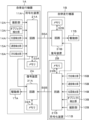
- the information processing system includes an autonomous mobile device 1, a transmission line NW, a decoding device 2, and a display device 3.
- the autonomous mobile device 1 is, for example, an autonomous mobile vehicle that delivers goods unmanned in a product delivery system.
- the autonomous mobile device 1 has an encoding device 11, a photographing unit 12, and an object detection unit 13. Although one autonomous mobile device 1 is shown in FIG. 1, there may be multiple autonomous mobile devices 1 with the same configuration.
- the encoding device 11 includes a circuit 21 and a memory 22 connected to the circuit 21.
- the circuit 21 is configured with a processor such as a CPU.
- the memory 22 is configured with any recording medium such as a ROM, RAM, HDD, SSD, or semiconductor memory.
- the memory 22 stores data to be processed by the circuit 21 or data in the middle of processing, etc.
- the photographing unit 12 is configured with a camera having an optical system and a CMOS image sensor, etc.
- the photographing unit 12 photographs the surroundings of the autonomous mobile device 1 (particularly the area ahead in the direction of movement).
- the object detection unit 27 is configured with LiDAR (Light Detection And Ranging) and the like.
- the object detection unit 27 detects objects that exist around the autonomous mobile device 1 in real space.
- the object detection unit 27 inputs real-space detection information, which is detection information in real space regarding an object, to the circuit 21.
- the real-space detection information includes the distance to the object, the direction in which the object is located, the shape of the object, etc.
- the transmission line NW is the Internet, a WAN (Wide Area Network), a LAN (Local Area Network), or any combination of these. It is desirable for the transmission line NW to be a private network in which secure communication is ensured by access restrictions.
- the decoding device 2 and the display device 3 are placed, for example, in a monitoring center where an operator who remotely monitors the autonomous mobile device 1 resides.
- the decryption device 2 includes a circuit 31 and a memory 32 connected to the circuit 31.
- the circuit 31 is configured with a processor such as a CPU.
- the memory 32 is configured with any recording medium such as a ROM, RAM, HDD, SSD, or semiconductor memory.
- the memory 32 stores data to be processed by the circuit 31 or data in the middle of processing.
- the display device 3 is a liquid crystal display or an organic EL display, etc.
- the circuit 21 of the encoding device 11 transmits the bit stream BS to the decoding device 2 via the transmission path NW.
- the circuit 31 of the decoding device 2 receives the bit stream BS and generates a display image for human vision by an operator.
- the display device 3 displays the display image.
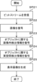
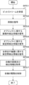
- FIG. 2 is a flowchart showing the flow of processing executed by circuit 21 of encoding device 11.
- step SP11 the circuit 21 acquires an image captured by the image capture unit 12.
- the image includes objects present around the autonomous mobile device 1.
- FIG. 3 is a diagram showing a schematic example of a driving situation of the autonomous mobile device 1.
- Autonomous mobile devices 1A and 1B and pedestrians 6A to 6C are present on a sidewalk 5.
- Autonomous mobile device 1A is driving in the upward direction on the page.
- Autonomous mobile device 1B is driving in the downward direction on the page, ahead of autonomous mobile device 1A in the direction of movement.
- Pedestrian 6A is walking in the right direction on the page, ahead of autonomous mobile device 1A in the direction of movement.
- Pedestrian 6B is walking in the downward direction on the page, ahead of autonomous mobile device 1A in the direction of movement.
- Pedestrian 6C is walking in the upward direction on the page, behind autonomous mobile device 1A in the direction of movement.
- FIG. 4 is a diagram showing a schematic example of an image 100 captured by the image capture unit 12 of the autonomous mobile device 1A.
- the image 100 includes the autonomous mobile device 1B and pedestrian 6B moving toward the autonomous mobile device (autonomous mobile device 1A), and a pedestrian 6A crossing in front of the autonomous mobile device.
- step SP12 the circuit 21 obtains real-space detection information about objects included in the image 100 from the object detection unit 13.
- the real-space detection information about the objects includes, for each of the objects, the autonomous mobile device 1B and the pedestrians 6A and 6B, the distance to the object, the direction in which the object exists, the shape of the object, and the like.
- Step SP12 may be executed simultaneously with step SP11.
- the circuit 21 analyzes the image 100 acquired in step SP11.
- the analysis of the image 100 includes object detection processing and object recognition processing, for example, using a machine-learned estimation model.
- the circuit 21 generates in-image detection information, which is detection information within the image 100 regarding objects contained in the image 100.
- the in-image detection information includes position information of objects within the image 100 as a result of the object detection processing.
- the in-image detection information may also include attribute information of objects within the image 100 as a result of the object recognition processing.
- the attributes represent the type of object, such as an autonomous driving device, a person, or a bicycle.
- FIG. 5 is a diagram showing a schematic example of the analysis results of the image 100 by the circuit 21.
- the circuit 21 sets a bounding box BB surrounding the object within the image 100 as position information of the object within the image 100. Specifically, the circuit 21 sets a bounding box BB1 surrounding the autonomous mobile device 1B, a bounding box BB2 surrounding the pedestrian 6A, and a bounding box BB3 surrounding the pedestrian 6B.
- the circuit 21 specifies the position and shape of the bounding box BB using the coordinate values of a specific vertex of the bounding box BB (e.g., the vertex in the upper left corner) and the height and width of the bounding box BB.
- the circuit 21 may specify the position and shape of the bounding box BB using the coordinate values of the center point of the bounding box BB and the height and width of the bounding box BB.
- the circuit 21 may specify the position and shape of the bounding box BB using the coordinate values of the four vertices of the bounding box BB.
- the circuit 21 may specify the position and shape of the bounding box BB using the coordinate values of two vertices located on the diagonal line of the bounding box BB.
- the circuit 21 also associates objects in real space detected by the object detection unit 13 with objects in the image 100 detected by image analysis.
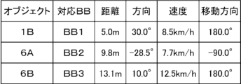
- FIG. 6 is a simplified diagram showing an example of real-space detection information and in-image detection information related to an object.
- the real-space detection information includes position information and movement information.
- the position information includes distance and direction.
- the movement information includes speed and movement direction.
- the circuit 21 calculates the speed and movement direction of the object based on the position detection results of the object detection unit 13 at multiple times. However, the calculation of the movement information including the speed and movement direction of the object may be performed by the circuit 31 of the decoding device 2 instead of the circuit 21 of the encoding device 11.
- the in-image detection information includes information indicating the position and shape of the corresponding bounding box BB.
- the origin of the coordinate system of the object detection unit 13 is the center point of the object detection unit 13, and the origin of the coordinate system of the autonomous mobile device 1A is the center point of the autonomous mobile device 1A, and the two are different. Therefore, the circuit 21 derives real-space detection information related to the object based on the detection value by the object detection unit 13 converted from the unique coordinate system of the object detection unit 13 to the common coordinate system of the autonomous mobile device 1A.
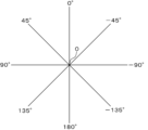
- FIG. 7 is a diagram showing an example of the coordinate system of the autonomous mobile device 1A.
- the coordinate system of the autonomous mobile device 1A is a circular coordinate system, and the origin O of the coordinate system is the center point of the autonomous mobile device 1A.
- An angle of 0° in the coordinate system corresponds to the movement direction of the autonomous mobile device 1A.
- the position of an object is indicated by the distance coordinate value and the angle coordinate value in the circular coordinate system.
- the movement direction of an object is indicated by the angle coordinate value in the circular coordinate system.
- the distance, direction, speed, and direction of movement are the relative distance, relative direction, relative speed, and relative direction of movement of the object with respect to the autonomous mobile device 1A.
- the corresponding bounding box BB is bounding box BB1
- the relative distance is 5.0 m
- the relative direction is 30.0°
- the relative speed is 8.5 km/h
- the relative movement direction is 180.0°.
- the corresponding bounding box BB is bounding box BB2
- the relative distance is 9.8 m
- the relative direction is -28.5°
- the relative speed is 7.7 km/h
- the relative movement direction is -90.0°.
- the corresponding bounding box BB is bounding box BB3
- the relative distance is 13.1 m
- the relative direction is 10.0°
- the relative speed is 12.5 km/h
- the relative movement direction is 180.0°.
- the coordinate system of the autonomous mobile device 1A is not limited to the above circular coordinate system, and may be a Cartesian coordinate system.
- the Cartesian coordinate system may indicate the position of an object by the X-axis value and the Y-axis value, with the forward/backward direction of the autonomous mobile device 1A as the X-axis, the left/right direction of the autonomous mobile device 1A as the Y-axis, and the center point of the autonomous mobile device 1A as the origin.
- step SP14 the circuit 21 encodes the image 100 acquired in step SP11 into a bit stream BS.
- FIG 8 is a simplified diagram showing the data structure of a bitstream BS.
- the bitstream BS has a header 41 and a payload 42.
- the header 41 includes an SEI (Supplemental Enhancement Information) area 43 for storing additional information.
- SEI Supplemental Enhancement Information
- the circuit 21 encodes the image 100 containing the object into the payload 42 of the bitstream BS.
- the circuit 21 encodes the intra-image detection information relating to the object into a bit stream BS.
- the circuit 21 encodes the intra-image detection information generated in step SP13 into a predetermined location in the header 41.
- the predetermined location is the SEI region 43.
- the predetermined location may be the VPS, SPS, PPS, PH, SH, APS, or a tile header, etc.
- the predetermined location may be an ARSEI (annotated region SEI) region for storing bounding box information.
- step SP16 the circuit 21 encodes the real space detection information related to the object into a bit stream BS.
- the circuit 21 encodes the real space detection information acquired in step SP12 into a predetermined location in the header 41.
- the predetermined location is the SEI area 43.
- the predetermined location may be the VPS, SPS, PPS, PH, SH, APS, or a tile header, etc.
- the predetermined location may be an ARSEI area for storing bounding box information. Note that steps SP14 to SP16 may be executed simultaneously.
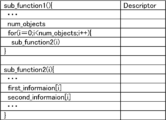
- FIG. 9 shows a simplified example of the syntax.
- num_objects indicates the number of objects contained in the image 100.
- first_information contains in-image detection information about the objects.
- second_information contains real-space detection information about the objects.
- step SP17 the circuit 21 transmits the bit stream BS to the decoding device 2.
- FIG. 10 is a flowchart showing the flow of processing executed by the circuit 31 of the decoding device 2.
- step SP21 the circuit 31 receives the bit stream BS from the autonomous mobile device 1A.
- step SP22 the circuit 31 decodes the image 100 including the object from the payload 42 of the bitstream BS.
- step SP23 the circuit 31 decodes intra-image detection information relating to the object from the header 41 of the bitstream BS. If the intra-image detection information is encoded in the SEI region 43 of the header 41, the circuit 31 decodes the intra-image detection information from the SEI region 43. If the intra-image detection information is encoded in the ARSEI region of the header 41, the circuit 31 decodes the intra-image detection information from the ARSEI region.
- step SP24 the circuit 31 decodes real space detection information related to the object from the header 41 of the bit stream BS. If the real space detection information is encoded in the SEI region 43 of the header 41, the circuit 31 decodes the real space detection information from the SEI region 43. If the real space detection information is encoded in the ARSEI region of the header 41, the circuit 31 decodes the real space detection information from the ARSEI region. Note that steps SP22 to SP24 may be executed simultaneously.
- step SP25 the circuit 31 generates a display image 200 for human vision by the operator based on the image and information decoded in steps SP22 to SP24.
- FIG. 11 is a simplified diagram showing an example of a display image 200.
- the display image 200 includes the image 100, display position information of an object in real space, and display movement information D1 to D3 of the object in real space.
- the display position information includes frames F1 to F3 corresponding to bounding boxes BB1 to BB3, and distance information indicating the relative distance of each object to the autonomous mobile device 1A.
- the circuit 31 uses the position information of the object in real space, which is included in the real space detection information decoded from the bit stream BS, as the display position information of the object.
- the display movement information D1 to D3 includes relative speed information indicating the relative speed of each object with respect to the autonomous mobile device 1A, and relative movement direction information indicating the relative movement direction of each object with respect to the autonomous mobile device 1A.
- the relative movement direction information is represented as a bold arrow.
- the circuit 31 uses the movement information of the object in the real space, which is included in the real space detection information decoded from the bit stream BS, as the display movement information D1 to D3 of the object.
- the circuit 31 also highlights, by using a thick line or coloring, frames F1, F3 that correspond to objects that may collide with or approach the host vehicle (autonomous mobile device 1A) among the multiple objects included in the display image 200.
- the circuit 31 determines whether or not there is a possibility of a collision or approach with the host vehicle based on the relative position, relative distance, and relative movement direction of the object with respect to the host vehicle. This allows an operator viewing the display image 200 to quickly identify an object that should be closely monitored among the multiple objects included in the display image 200.
- the encoding device 11 of this embodiment by encoding the on-screen detection information and real-space detection information regarding objects present around the autonomous driving device 1 into a bit stream BS, this information can be effectively utilized on the decoding device 2 side that receives the bit stream BS, thereby improving the safety of the autonomous driving device 1, such as collision avoidance performance.
- the intra-image detection information includes position information of the object within the image 100, so that the position information of the object within the image 100 can be effectively utilized on the decoding device 2 side.
- the real space detection information includes position information and movement information of the object in real space, so that the decoding device 2 can effectively utilize the position information and movement information of the object in real space. Note that one of the position information and movement information of the object in real space may be omitted.
- the position information of an object includes coordinate values in a circular coordinate system based on the autonomous mobile device 1, so that the position of the object can be accurately identified by the position information including the coordinate values.
- the object movement information includes the relative speed and relative movement direction of the object with respect to the autonomous mobile device 1, so that the speed and movement direction of the object can be accurately identified.
- the in-image detection information and real-space detection information regarding the object can be encoded in the SEI region 43 of the bitstream, allowing easy processing on the decoding device 2 side.
- real-space detection information regarding the object can be appropriately derived by a conversion process from the unique coordinate system of the object detection unit 13 to the common coordinate system of the autonomous mobile device 1.
- the decoding device 2 can effectively utilize on-screen detection information and real-space detection information regarding objects present around the autonomous mobile device 1, thereby improving the safety of the autonomous mobile device 1, such as collision avoidance performance. It can also improve decision-making regarding the operation of the autonomous mobile device 1 to improve the safety of the autonomous mobile device 1 in complex environments.
- the intra-image detection information includes position information of the object within the image 100, so that the position information of the object within the image 100 can be effectively utilized.
- the real space detection information includes position information and movement information of an object in real space, so that the position information and movement information of an object in real space can be effectively utilized.
- the position information of an object includes coordinate values in a circular coordinate system based on the autonomous mobile device 1, so that the position of the object can be accurately identified by the position information including the coordinate values.
- the object movement information includes the object's relative speed and relative movement direction with respect to the autonomous mobile device 1, so that the object's speed and movement direction can be accurately identified.
- the in-image detection information and real-space detection information relating to the object are encoded in the SEI region 43 of the bitstream, which allows easy processing on the decoding device 2 side.
- the operator can instantly and accurately grasp the situation around the autonomous mobile device 1 by visually checking the display image 200, which includes display position information and display movement information of an object in real space.
- the position information of the object included in the real space detection information is used as the display position information
- the movement information of the object included in the real space detection information is used as the display movement information, so that the display position information and the display movement information can be easily generated.
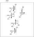
- the display image 201 includes a figure G0 imitating the autonomous mobile device 1A which is the vehicle itself, a figure G1 imitating the autonomous mobile device 1B which is an object, a figure G2 imitating a pedestrian 6A which is an object, a figure G3 imitating a pedestrian 6B which is an object, position information for display of the objects in real space, and movement information D1 to D3 for display of the objects in real space.
- the display image 201 has a coordinate plane of a circular coordinate system with the position of the figure G0 as the origin O.
- the display position information includes figures G1 to G3 and distance information indicating the relative distance of each object with respect to the autonomous mobile device 1A.
- the distance coordinate value L1 and the angle coordinate value ⁇ 1 of the circular coordinate system for figure G1 correspond to the distance coordinate value and the angle coordinate value included in the real space detection information for the autonomous mobile device 1B.
- the display movement information D1 to D3 includes relative speed information indicating the relative speed of each object with respect to the autonomous mobile device 1A, and relative movement direction information indicating the relative movement direction of each object with respect to the autonomous mobile device 1A.
- the relative movement direction information is represented as a bold arrow graphic.
- the circuit 31 may highlight the figures G1 and G3 that correspond to objects that may collide with or approach the player's aircraft by flashing or coloring them, among the multiple objects.
- an operator viewing the display image 201 can quickly identify which of multiple objects should be the focus of attention for monitoring.
- (Second Modification) 13 is a simplified diagram showing an example of a display image 202 as a modified example of the display image 200.
- the display image 202 includes figures G0 to G3, display position information of objects in real space, and display movement information D1 to D3 of the objects in real space.
- the display image 202 has a coordinate plane of a Cartesian coordinate system with the position of the figure G0 as the origin O.
- the Cartesian coordinate system has orthogonal X-axis and Y-axis.
- the coordinate system of the autonomous mobile device 1A is a Cartesian coordinate system
- the origin O of the coordinate system is the center point of the autonomous mobile device 1A.
- the X-axis of the coordinate system corresponds to the direction of movement of the autonomous mobile device 1A.
- the position of an object is indicated by the X-coordinate value and the Y-coordinate value in the Cartesian coordinate system.
- the display position information includes figures G1 to G3 and distance information indicating the relative distance of each object to the autonomous mobile device 1A.
- the X coordinate value X1 and the Y coordinate value Y1 in the Cartesian coordinate system for figure G1 correspond to the X coordinate value and the Y coordinate value included in the real space detection information for the autonomous mobile device 1B.
- the display movement information D1 to D3 includes relative speed information indicating the relative speed of each object with respect to the autonomous mobile device 1A, and relative movement direction information indicating the relative movement direction of each object with respect to the autonomous mobile device 1A.
- the relative movement direction information is represented as a bold arrow graphic.
- the circuit 31 may highlight the figures G1 and G3 that correspond to objects that may collide with or approach the player's aircraft by flashing or coloring them, among the multiple objects.
- an operator viewing the display image 201 can quickly identify which of multiple objects should be the focus of attention for monitoring.
- FIG. 14 is a diagram showing figure G1 extracted from the display image 202 shown in FIG. 13.
- Circuit 31 calculates display movement information D1 for an object based on multiple pieces of position information at multiple times for the object corresponding to figure G1, which is included in the real space detection information decoded from the bit stream BS.
- Circuit 31 calculates the movement distance and movement direction of the object in real space based on the X coordinate value X1(t) and Y coordinate value Y1(t) of the object at a certain time t, and the X coordinate value X1(t-1) and Y coordinate value Y1(t-1) of the object at an earlier time t-1.
- Circuit 31 also calculates the speed of the object based on the calculated movement distance and the time difference ⁇ t between time t and time t-1.
- Equation (1) shows an example of a formula for calculating the velocity V of an object.
- Equation (2) shows an example of a formula for calculating the object's movement direction A.
- the circuit 31 generates display movement information D1 that includes speed information indicating the calculated speed and movement direction information indicating the calculated movement direction. Note that, although the example shown in FIG. 14 is explained using a Cartesian coordinate system, similar processing is also possible for a circular coordinate system.
- the circuit 31 can appropriately calculate the display movement information D1 to D3 of the object based on multiple pieces of position information of the object at multiple times in real space.
- (Fourth Modification) 15 is a simplified diagram showing an example of the display image 201.
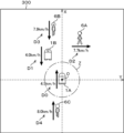
- a boundary Z is set around the figure G0.
- the boundary Z corresponds to a circle having a radius of, for example, 1 m and centered on the position of the autonomous mobile device 1A in real space.
- circuit 31 determines that there is a high possibility that autonomous mobile device 1A will collide with the object, and displays an alert in display image 201. For example, when autonomous mobile device 1B corresponding to figure G1 enters boundary Z, circuit 31 highlights figure G0 and/or figure G1 by blinking or coloring, etc. Note that although the example shown in FIG. 15 describes a circular coordinate system, similar processing is also possible for a Cartesian coordinate system.
- an operator viewing the display image 201 can quickly grasp the occurrence of a situation in which there is a high possibility that the autonomous mobile device 1A will collide with an object, and can perform collision avoidance control, such as an emergency stop of the autonomous mobile device 1A by remote control.
- collision avoidance control may be performed by automatic control by the circuit 31, instead of manual operation by the operator.
- (Fifth Modification) 16 is a diagram showing a simplified configuration of an information processing system according to Modification 5.
- the autonomous mobile device 1 includes a position detection unit 14, a speed detection unit 15, and an orientation detection unit 16 in addition to the configuration shown in FIG.
- the position detection unit 14, the speed detection unit 15, and the orientation detection unit 16 input real-space detection information, which is detection information in real space regarding the autonomous mobile device 1, to the circuit 21.
- the real-space detection information includes position information and movement information.
- the position information regarding the autonomous mobile device 1 includes an absolute position.
- the movement information regarding the autonomous mobile device 1 includes an absolute speed and an absolute movement direction.
- the position detection unit 14 is configured with a GPS receiver and the like.
- the position detection unit 14 detects the absolute position of the autonomous mobile device 1 and inputs the detected value to the circuit 21.
- the absolute position is a coordinate value (latitude and longitude) in a geographic coordinate system such as world coordinates.
- the speed detection unit 15 is configured with a tachometer and the like. The speed detection unit 15 detects the absolute speed of the autonomous mobile device 1 and inputs the detected value to the circuit 21.
- the orientation detection unit 16 is configured with an acceleration sensor, a gyro sensor, or the like.
- the orientation detection unit 16 detects the forward direction or absolute movement direction of the autonomous mobile device 1, and inputs the detection value to the circuit 21.
- the circuit 21 derives real-space detection information regarding the autonomous mobile device 1 based on values obtained by converting the detection values from the position detection unit 14, the speed detection unit 15, and the direction detection unit 16 from the unique coordinate system of each detection unit into the common coordinate system of the autonomous mobile device 1.
- FIG. 17 is a flowchart showing the flow of processing executed by the circuit 21 of the encoding device 11. Explanations of processing similar to that shown in the flowchart in FIG. 2 will be omitted.
- step SP31 the circuit 21 acquires real-space detection information regarding the autonomous mobile device 1A from the position detection unit 14, the speed detection unit 15, and the orientation detection unit 16.
- step SP32 the circuit 21 encodes the real space detection information related to the autonomous mobile device 1A into a bit stream BS.
- the circuit 21 encodes the real space detection information acquired in step SP31 into a predetermined location in the header 41.
- the predetermined location is the SEI area 43.
- the predetermined location may be the VPS, SPS, PPS, PH, SH, APS, or a tile header, etc. Alternatively, the predetermined location may be the ARSEI area.
- FIG. 18 shows a simplified example of syntax.
- third_information includes real-space detection information related to the autonomous mobile device 1A.
- FIG. 19 is a flowchart showing the flow of processing executed by the circuit 31 of the decoding device 2. Explanations of processing similar to that shown in the flowchart in FIG. 10 will be omitted.
- step SP33 the circuit 31 decodes the real space detection information related to the autonomous mobile device 1A from the header 41 of the bit stream BS.
- step SP25 circuit 31 generates display image 200 for human vision by the operator based on the images and information decoded in steps SP22 to SP24 and SP33.
- FIG. 20 is a simplified diagram showing an example of display image 200.
- circuit 31 may convert relative position information of an object in real space decoded in step SP24 into absolute position information of the object in real space using absolute position information of autonomous mobile device 1A in real space decoded in step SP33.
- the circuit 31 may also convert the relative movement information of the object in real space decoded in step SP24 into absolute movement information of the object in real space using the absolute movement information of the autonomous mobile device 1A in real space decoded in step SP33.
- the relative speed of each object with respect to the autonomous mobile device 1A is converted into an absolute speed.
- the circuit 31 may also include in the display image 200 the absolute movement information and absolute position information of the autonomous mobile device 1A in real space decoded in step SP33.
- the display image 200 includes host information C0 indicating the absolute speed and absolute position of the autonomous mobile device 1A.
- the host information C0 may further include the absolute movement direction of the autonomous mobile device 1A.
- the absolute movement direction may be indicated, for example, by orientation information indicating the movement direction of the autonomous mobile device 1A.
- processing according to this modified example may be applied not only to display image 200 but also to display images 201 and 202.
- the absolute position information and absolute movement information of the autonomous mobile device 1A in real space can be effectively utilized on the decoding device 2 side.
- FIG. 21 is a simplified diagram showing an example of a display image 203 as a modified example of the display image 202.
- the display image 203 includes a figure G4 that resembles a pedestrian 6C, which is an object, in addition to the figures G0 to G3 shown in Fig. 13.
- the pedestrian 6C is photographed by the imaging unit 12 of the autonomous mobile device 1B.
- the circuit 21 of the encoding device 11 of the autonomous mobile device 1B encodes the image photographed by the imaging unit 12, intra-image detection information relating to objects contained in the image, and real-space detection information relating to the objects into a bit stream BS and transmits it to the decoding device 2.
- the real-space detection information includes relative position information and relative movement information of the pedestrian 6C with respect to the autonomous mobile device 1B, and absolute position information and absolute movement information of the autonomous mobile device 1B.
- the circuit 31 of the decoding device 2 receives multiple bit streams BS from multiple autonomous mobile devices 1A, 1B.
- the circuit 31 generates a display image 203 based on multiple images decoded from the multiple bit streams BS.
- the circuit 31 calculates absolute position information and absolute movement information of the pedestrian 6C by converting the relative position information and relative movement information of the pedestrian 6C with respect to the autonomous mobile device 1B using the absolute position information and absolute movement information of the autonomous mobile device 1B. This makes it possible to include in the display image 203 a figure G4 corresponding to the pedestrian 6C that cannot be photographed by the photographing unit 12 of the autonomous mobile device 1A.
- the display movement information D0 to D4 includes absolute speed information indicating the absolute speed of each object and absolute movement direction information indicating the absolute movement direction of each object. Note that although the Cartesian coordinate system has been described in the example shown in FIG. 21, similar processing is also possible for a circular coordinate system.
- multiple images captured by multiple autonomous mobile devices 1A and 1B can complement each other's blind spots during capture, improving the convenience of the display image 203.
- FIG. 22 is a simplified diagram showing the configuration of an information processing system according to a second embodiment of the present disclosure.
- the information processing system includes autonomous mobile devices 1A and 1B.
- the autonomous mobile device 1A has an encoding device 11A, a photographing unit 12A, an object detection unit 13A, a position detection unit 14A, a speed detection unit 15A, an orientation detection unit 16A, a decoding device 2A, and a driving unit 17A.
- the encoding device 11A includes a circuit 21A and a memory 22A.
- the decoding device 2A includes a circuit 31A and a memory 32A.
- the driving unit 17A is configured with the traveling motor of the autonomous mobile device 1A, etc.
- the autonomous mobile device 1B has an encoding device 11B, a photographing unit 12B, an object detection unit 13B, a position detection unit 14B, a speed detection unit 15B, an orientation detection unit 16B, a decoding device 2B, and a driving unit 17B.
- the encoding device 11B includes a circuit 21B and a memory 22B.
- the decoding device 2B includes a circuit 31B and a memory 32B.
- the driving unit 17B is configured with the traveling motor of the autonomous mobile device 1B, etc.
- Circuit 21B of encoding device 11B transmits bit stream BSB, and circuit 31A of decoding device 2A receives bit stream BSB.
- Encoding device 11A is mounted on autonomous mobile device 1B, and decoding device 2A is mounted on autonomous mobile device 1A that is different from autonomous mobile device 1B.
- circuit 21A of encoding device 11A transmits bit stream BSA, and circuit 31B of decoding device 2B receives bit stream BSA.
- FIG. 23 is a flowchart showing the flow of processing executed by circuit 31A of decoding device 2A.
- step SP51 circuit 31A receives bit stream BSB from autonomous mobile device 1B.
- circuit 31A decodes image 100B, which includes an object, from payload 42 of bitstream BSB.
- FIG. 24 is a diagram showing an example of an image 100B captured by the image capture unit 12B of the autonomous mobile device 1B.
- Image 100B includes, as objects, the autonomous mobile device 1A and a pedestrian 6C walking behind the autonomous mobile device 1A.
- step SP53 circuit 31A decodes intra-image detection information relating to objects contained in image 100B from header 41 of bitstream BSB.
- step SP54 circuit 31A decodes real space detection information regarding objects contained in image 100B from header 41 of bit stream BSB.
- step SP55 the circuit 31A decodes the real space detection information related to the autonomous mobile device 1B from the header 41 of the bit stream BSB.
- step SP56 the circuit 31A obtains from the circuit 21A the image 100 captured by the image capture unit 12A of the autonomous mobile device 1A, the intra-image detection information and real-space detection information relating to objects contained in the image 100, and the real-space detection information relating to the autonomous mobile device 1A.
- circuit 31A controls the driving of autonomous mobile device 1A by drive unit 17A based on the in-image detection information and real-space detection information regarding the object decoded from bit stream BSB and the in-image detection information and real-space detection information regarding the object acquired from circuit 21A.
- the circuit 31A generates a map 300 showing the position information and movement information of objects present around the autonomous mobile device 1A.
- the circuit 31A converts the real space detection information of the object using a coordinate system based on the autonomous mobile device 1B, which is decoded from the bit stream BSB, into real space detection information of the object using a coordinate system based on the autonomous mobile device 1A.
- the circuit 31A calculates the absolute position information and absolute movement information of the pedestrian 6C by converting the relative position information and relative movement information of the pedestrian 6C with respect to the autonomous mobile device 1B using the absolute position information and absolute movement information of the autonomous mobile device 1B.
- the circuit 31A includes the absolute position information and absolute movement information of the object corresponding to the pedestrian 6C in the map 300.
- the circuit 31A may calculate the relative position information and relative speed information of the pedestrian 6C with respect to the autonomous mobile device 1A by converting the absolute position information and absolute movement information of the pedestrian 6C using the absolute position information and absolute movement information of the autonomous mobile device 1A.
- the circuit 31A may include in the map 300 the relative position information and relative movement information of the pedestrian 6C with respect to the autonomous mobile device 1A.
- FIG. 25 is a diagram showing a simplified example of map 300.
- Map 300 has a coordinate plane of a Cartesian coordinate system with the absolute position of autonomous mobile device 1A as origin O and the direction of movement of autonomous mobile device 1A as X-axis.
- Map 300 includes absolute position information and absolute movement information of objects corresponding to autonomous mobile device 1B and pedestrians 6A and 6B, as well as absolute position information and absolute movement information of an object corresponding to pedestrian 6C.
- a boundary Z is set around the autonomous mobile device 1A.
- the boundary Z corresponds to a circle with a radius of, for example, 1 m, centered on the position of the autonomous mobile device 1A in real space.
- the circuit 31 determines that there is a high possibility that the autonomous mobile device 1A will collide with the object, and performs collision avoidance control, such as bringing the autonomous mobile device 1A to an emergency stop using the drive unit 17A.
- the circuit 31A may generate a table that lists the position information and movement information of objects present around the autonomous mobile device 1A.
- multiple autonomous mobile devices 1A, 1B communicate with each other to exchange in-image detection information and real-space detection information related to objects, so that the autonomous mobile device 1A can effectively use this information received from another autonomous mobile device 1B in controlling the operation of its own vehicle, thereby improving the safety of the autonomous mobile device 1, such as its collision avoidance performance.
- This disclosure is particularly useful for application to product delivery systems or transportation systems that use autonomous mobile devices.
Landscapes
- Engineering & Computer Science (AREA)
- Multimedia (AREA)
- Signal Processing (AREA)
- Physics & Mathematics (AREA)
- General Physics & Mathematics (AREA)
- Theoretical Computer Science (AREA)
- Computer Vision & Pattern Recognition (AREA)
- Image Analysis (AREA)
- Traffic Control Systems (AREA)
Abstract
Description
自律走行車等の自律走行機器を用いた商品配送システムでは、無人の自律走行機器が歩行者と同程度の速度で歩道を走行し、商品を配送する。自律走行機器には、カメラ、GPS受信機、及び障害物センサ等が搭載され、安全走行の実現のためにそれらが相互に機能を補完し合う。しかし、非常に複雑な環境下においても確実に安全走行を行うには技術的な限界があり、問題が発生した場合には遠隔操作による人間のオペレータの介入が必要となる。そのため、自律走行機器は、自機に搭載されたカメラによって撮影された画像を、オペレータが常駐している監視センタにリアルタイムで送信する。
以下、本開示の実施形態について、図面を用いて詳細に説明する。なお、異なる図面において同一の符号を付した要素は、同一又は相応する要素を示すものとする。
図1は、本開示の第1実施形態に係る情報処理システムの構成を簡略化して示す図である。情報処理システムは、自律走行機器1、伝送路NW、復号装置2、及び表示装置3を備えている。
図12は、表示画像200の変形例として表示画像201の一例を簡略化して示す図である。表示画像201は、自機である自律走行機器1Aを模した図形G0と、オブジェクトである自律走行機器1Bを模した図形G1と、オブジェクトである歩行者6Aを模した図形G2と、オブジェクトである歩行者6Bを模した図形G3と、実空間におけるオブジェクトの表示用位置情報と、実空間におけるオブジェクトの表示用移動情報D1~D3とを含む。表示画像201は、図形G0の位置を原点Oとする円座標系の座標平面を有している。
図13は、表示画像200の変形例として表示画像202の一例を簡略化して示す図である。表示画像202は、図形G0~G3と、実空間におけるオブジェクトの表示用位置情報と、実空間におけるオブジェクトの表示用移動情報D1~D3とを含む。表示画像202は、図形G0の位置を原点Oとするデカルト座標系の座標平面を有している。デカルト座標系は、直交するX軸及びY軸を有する。
本変形例では、ビットストリームBSから復号された実空間検出情報に、オブジェクトの移動情報(速度及び移動方向)が含まれていない場合の対応について説明する。


図15は、表示画像201の一例を簡略化して示す図である。図形G0を中心として、その周囲に境界Zが設定されている。境界Zは、実空間において自律走行機器1Aの位置を中心とする半径が例えば1mの円に相当する。
図16は、第5変形例に係る情報処理システムの構成を簡略化して示す図である。自律走行機器1は、図1に示した構成に加えて、位置検出部14、速度検出部15、及び方位検出部16を備えている。
図21は、表示画像202の変形例として表示画像203の一例を簡略化して示す図である。表示画像203は、図13に示した図形G0~G3に加えて、オブジェクトである歩行者6Cを模した図形G4を含む。
第2実施形態では、複数の自律走行機器1間での通信について説明する。
Claims (28)
- 回路と、
前記回路に接続されたメモリと、
を備え、
前記回路は、
撮影部を有する自律走行機器からビットストリームを受信し、
前記撮影部によって撮影された画像を、前記ビットストリームから復号し、
前記画像に含まれるオブジェクトに関する、前記画像内における検出情報である画像内検出情報を、前記ビットストリームから復号し、
前記オブジェクトに関する、実空間における検出情報である実空間検出情報を、前記ビットストリームから復号する、
復号装置。 - 前記オブジェクトに関する前記画像内検出情報は、前記画像内における前記オブジェクトの位置情報を含む、
請求項1に記載の復号装置。 - 前記オブジェクトに関する前記実空間検出情報は、前記実空間における前記オブジェクトの位置情報、及び、前記実空間における前記オブジェクトの移動情報の少なくとも一方を含む、
請求項1に記載の復号装置。 - 前記オブジェクトの前記位置情報は、
前記自律走行機器を基準とした円座標系における座標値、
前記自律走行機器を基準としたデカルト座標系における座標値、又は、
地理座標系における座標値
を含む、
請求項3に記載の復号装置。 - 前記オブジェクトの前記移動情報は、
前記オブジェクトの絶対速度又は前記自律走行機器に対する前記オブジェクトの相対速度と、前記オブジェクトの絶対移動方向又は前記自律走行機器に対する前記オブジェクトの相対移動方向との少なくとも一方を含む、
請求項3に記載の復号装置。 - 前記回路は、さらに、前記自律走行機器に関する実空間検出情報を前記ビットストリームから復号し、
前記自律走行機器に関する前記実空間検出情報は、前記実空間における前記自律走行機器の位置情報、及び、前記実空間における前記自律走行機器の移動情報を含む、
請求項1に記載の復号装置。 - 前記自律走行機器の前記位置情報は、地理座標系における座標値を含む、
請求項6に記載の復号装置。 - 前記自律走行機器の前記移動情報は、前記自律走行機器の絶対速度及び絶対移動方向の少なくとも一方を含む、
請求項6に記載の復号装置。 - 前記回路は、前記オブジェクトに関する前記画像内検出情報及び前記実空間検出情報と、前記自律走行機器に関する前記実空間検出情報とを、前記ビットストリームのSEI(Supplemental Enhancement Information)領域から復号する、
請求項6に記載の復号装置。 - 前記回路は、さらに、ヒューマンビジョンのための表示画像を生成し、
前記表示画像は、
前記オブジェクトと、
前記実空間における前記オブジェクトの表示用位置情報、及び、前記実空間における前記オブジェクトの表示用移動情報の少なくとも一方と、
を含む、
請求項1に記載の復号装置。 - 前記自律走行機器は複数の自律走行機器を含み、
前記回路は、前記複数の自律走行機器から受信した複数のビットストリームから復号した複数の画像に基づいて、前記表示画像を生成する、
請求項10に記載の復号装置。 - 前記回路は、
前記ビットストリームから復号された、前記オブジェクトに関する前記実空間検出情報に含まれる、前記実空間における前記オブジェクトの位置情報を、前記オブジェクトの前記表示用位置情報として用い、
前記ビットストリームから復号された、前記オブジェクトに関する前記実空間検出情報に含まれる、前記実空間における前記オブジェクトの移動情報を、前記オブジェクトの前記表示用移動情報として用いる、
請求項10に記載の復号装置。 - 前記回路は、
さらに、前記実空間における前記自律走行機器の位置情報と、前記実空間における前記自律走行機器の移動情報とを、前記ビットストリームから復号し、
前記ビットストリームから復号された、前記オブジェクトに関する前記実空間検出情報に含まれる、前記実空間における前記オブジェクトの位置情報を、前記ビットストリームから復号された、前記実空間における前記自律走行機器の前記位置情報を用いて変換することにより、前記オブジェクトの前記表示用位置情報を算出し、
前記ビットストリームから復号された、前記オブジェクトに関する前記実空間検出情報に含まれる、前記実空間における前記オブジェクトの移動情報を、前記ビットストリームから復号された、前記実空間における前記自律走行機器の前記移動情報を用いて変換することにより、前記オブジェクトの前記表示用移動情報を算出する、
請求項10に記載の復号装置。 - 前記回路は、前記ビットストリームから復号された、前記オブジェクトに関する前記実空間検出情報に含まれる、前記実空間における前記オブジェクトの複数の時刻における複数の位置情報に基づいて、前記オブジェクトの前記表示用移動情報を算出する、
請求項10に記載の復号装置。 - 前記復号装置は、前記自律走行機器とは別の自律走行機器に搭載され、
前記回路は、さらに、前記自律走行機器から受信した前記ビットストリームから復号された、前記オブジェクトに関する前記画像内検出情報及び前記実空間検出情報と、前記別の自律走行機器が有する撮影部によって撮影された画像に含まれるオブジェクトに関する画像内検出情報及び実空間検出情報とに基づいて、前記別の自律走行機器の動作を制御する、
請求項1に記載の復号装置。 - 前記回路は、前記自律走行機器から受信した前記ビットストリームから復号された、前記自律走行機器を基準とした座標系を用いた、前記オブジェクトに関する前記実空間検出情報を、前記別の自律走行機器を基準とした座標系を用いた、前記オブジェクトに関する前記実空間検出情報に変換する、
請求項15に記載の復号装置。 - 撮影部を有する自律走行機器に搭載される符号化装置であって、
回路と、
前記回路に接続されたメモリと、
を備え、
前記回路は、
前記撮影部によって撮影された画像を、ビットストリームに符号化し、
前記画像に含まれるオブジェクトに関する、前記画像内における検出情報である画像内検出情報を、前記ビットストリームに符号化し、
前記オブジェクトに関する、実空間における検出情報である実空間検出情報を、前記ビットストリームに符号化する、
符号化装置。 - 前記オブジェクトに関する前記画像内検出情報は、前記画像内における前記オブジェクトの位置情報を含む、
請求項17に記載の符号化装置。 - 前記オブジェクトに関する前記実空間検出情報は、前記実空間における前記オブジェクトの位置情報、及び、前記実空間における前記オブジェクトの移動情報の少なくとも一方を含む、
請求項17に記載の符号化装置。 - 前記オブジェクトの前記位置情報は、
前記自律走行機器を基準とした円座標系における座標値、
前記自律走行機器を基準としたデカルト座標系における座標値、又は、
地理座標系における座標値
を含む、
請求項19に記載の符号化装置。 - 前記オブジェクトの前記移動情報は、
前記オブジェクトの絶対速度又は前記自律走行機器に対する前記オブジェクトの相対速度と、前記オブジェクトの絶対移動方向又は前記自律走行機器に対する前記オブジェクトの相対移動方向との少なくとも一方を含む、
請求項19に記載の符号化装置。 - 前記回路は、さらに、前記自律走行機器に関する実空間検出情報を前記ビットストリームに符号化し、
前記自律走行機器に関する前記実空間検出情報は、前記実空間における前記自律走行機器の位置情報、及び、前記実空間における前記自律走行機器の移動情報を含む、
請求項17に記載の符号化装置。 - 前記自律走行機器の前記位置情報は、地理座標系における座標値を含む、
請求項22に記載の符号化装置。 - 前記自律走行機器の前記移動情報は、前記自律走行機器の絶対速度及び絶対移動方向の少なくとも一方を含む、
請求項22に記載の符号化装置。 - 前記回路は、前記オブジェクトに関する前記画像内検出情報及び前記実空間検出情報と、前記自律走行機器に関する前記実空間検出情報とを、前記ビットストリームのSEI(Supplemental Enhancement Information)領域に符号化する、
請求項22に記載の符号化装置。 - 前記自律走行機器は、前記実空間において前記オブジェクトを検出する検出部をさらに有し、
前記回路は、前記検出部による検出値を前記検出部の座標系から前記自律走行機器の座標系に変換した値に基づいて、前記オブジェクトに関する前記実空間検出情報を導出する、
請求項17に記載の符号化装置。 - 復号装置が、
撮影部を有する自律走行機器からビットストリームを受信し、
前記撮影部によって撮影された画像を、前記ビットストリームから復号し、
前記画像に含まれるオブジェクトに関する、前記画像内における検出情報である画像内検出情報を、前記ビットストリームから復号し、
前記オブジェクトに関する、実空間における検出情報である実空間検出情報を、前記ビットストリームから復号する、
復号方法。 - 撮影部を有する自律走行機器に搭載される符号化装置が、
前記撮影部によって撮影された画像を、ビットストリームに符号化し、
前記画像に含まれるオブジェクトに関する、前記画像内における検出情報である画像内検出情報を、前記ビットストリームに符号化し、
前記オブジェクトに関する、実空間における検出情報である実空間検出情報を、前記ビットストリームに符号化する、
符号化方法。
Priority Applications (4)
| Application Number | Priority Date | Filing Date | Title |
|---|---|---|---|
| EP23900394.0A EP4614989A4 (en) | 2022-12-05 | 2023-11-13 | DECODING DEVICE, CODING DEVICE, DECODING METHOD, AND CODING METHOD |
| CN202380083478.2A CN120303945A (zh) | 2022-12-05 | 2023-11-13 | 解码装置、编码装置、解码方法以及编码方法 |
| JP2024562643A JPWO2024122273A1 (ja) | 2022-12-05 | 2023-11-13 | |
| US19/223,418 US20250294190A1 (en) | 2022-12-05 | 2025-05-30 | Decoding device, encoding device, decoding method, and encoding method |
Applications Claiming Priority (2)
| Application Number | Priority Date | Filing Date | Title |
|---|---|---|---|
| US202263430118P | 2022-12-05 | 2022-12-05 | |
| US63/430,118 | 2022-12-05 |
Related Child Applications (1)
| Application Number | Title | Priority Date | Filing Date |
|---|---|---|---|
| US19/223,418 Continuation US20250294190A1 (en) | 2022-12-05 | 2025-05-30 | Decoding device, encoding device, decoding method, and encoding method |
Publications (1)
| Publication Number | Publication Date |
|---|---|
| WO2024122273A1 true WO2024122273A1 (ja) | 2024-06-13 |
Family
ID=91378941
Family Applications (1)
| Application Number | Title | Priority Date | Filing Date |
|---|---|---|---|
| PCT/JP2023/040738 Ceased WO2024122273A1 (ja) | 2022-12-05 | 2023-11-13 | 復号装置、符号化装置、復号方法、及び符号化方法 |
Country Status (5)
| Country | Link |
|---|---|
| US (1) | US20250294190A1 (ja) |
| EP (1) | EP4614989A4 (ja) |
| JP (1) | JPWO2024122273A1 (ja) |
| CN (1) | CN120303945A (ja) |
| WO (1) | WO2024122273A1 (ja) |
Citations (4)
| Publication number | Priority date | Publication date | Assignee | Title |
|---|---|---|---|---|
| WO2018038131A1 (ja) * | 2016-08-26 | 2018-03-01 | パナソニック インテレクチュアル プロパティ コーポレーション オブ アメリカ | 三次元情報処理方法及び三次元情報処理装置 |
| WO2019215704A1 (en) * | 2018-05-11 | 2019-11-14 | Telefonaktiebolaget Lm Ericsson (Publ) | Configurable dci formatting indicator |
| US20210217200A1 (en) * | 2020-01-10 | 2021-07-15 | Lg Electronics Inc. | Point cloud data transmission device, point cloud data transmission method, point cloud data reception device, and point cloud data reception method |
| US20210278840A1 (en) | 2019-06-04 | 2021-09-09 | Lg Electronics Inc. | Autonomous vehicle and control method thereof |
Family Cites Families (6)
| Publication number | Priority date | Publication date | Assignee | Title |
|---|---|---|---|---|
| US10599150B2 (en) * | 2016-09-29 | 2020-03-24 | The Charles Stark Kraper Laboratory, Inc. | Autonomous vehicle: object-level fusion |
| US20220103789A1 (en) * | 2019-01-31 | 2022-03-31 | Lg Electronics Inc. | Method for sharing images between vehicles |
| GB2596464B (en) * | 2019-02-25 | 2024-05-01 | Mobileye Vision Technologies Ltd | Systems and methods for vehicle navigation |
| CN115735168A (zh) * | 2020-04-01 | 2023-03-03 | 移动眼视觉科技有限公司 | 用于对交通工具进行导航的控制回路 |
| US12181878B2 (en) * | 2020-10-22 | 2024-12-31 | Waymo Llc | Velocity estimation and object tracking for autonomous vehicle applications |
| CN117571001A (zh) * | 2021-01-08 | 2024-02-20 | 御眼视觉技术有限公司 | 用于公共速度映射和导航的系统和方法 |
-
2023
- 2023-11-13 EP EP23900394.0A patent/EP4614989A4/en active Pending
- 2023-11-13 JP JP2024562643A patent/JPWO2024122273A1/ja active Pending
- 2023-11-13 WO PCT/JP2023/040738 patent/WO2024122273A1/ja not_active Ceased
- 2023-11-13 CN CN202380083478.2A patent/CN120303945A/zh active Pending
-
2025
- 2025-05-30 US US19/223,418 patent/US20250294190A1/en active Pending
Patent Citations (4)
| Publication number | Priority date | Publication date | Assignee | Title |
|---|---|---|---|---|
| WO2018038131A1 (ja) * | 2016-08-26 | 2018-03-01 | パナソニック インテレクチュアル プロパティ コーポレーション オブ アメリカ | 三次元情報処理方法及び三次元情報処理装置 |
| WO2019215704A1 (en) * | 2018-05-11 | 2019-11-14 | Telefonaktiebolaget Lm Ericsson (Publ) | Configurable dci formatting indicator |
| US20210278840A1 (en) | 2019-06-04 | 2021-09-09 | Lg Electronics Inc. | Autonomous vehicle and control method thereof |
| US20210217200A1 (en) * | 2020-01-10 | 2021-07-15 | Lg Electronics Inc. | Point cloud data transmission device, point cloud data transmission method, point cloud data reception device, and point cloud data reception method |
Non-Patent Citations (1)
| Title |
|---|
| See also references of EP4614989A4 |
Also Published As
| Publication number | Publication date |
|---|---|
| CN120303945A (zh) | 2025-07-11 |
| JPWO2024122273A1 (ja) | 2024-06-13 |
| EP4614989A4 (en) | 2026-03-25 |
| EP4614989A1 (en) | 2025-09-10 |
| US20250294190A1 (en) | 2025-09-18 |
Similar Documents
| Publication | Publication Date | Title |
|---|---|---|
| KR102859653B1 (ko) | 신호 처리 장치 및 신호 처리 방법, 컴퓨터 판독가능 매체, 그리고 이동체 | |
| JP7586689B2 (ja) | LiDAR知覚のためのマルチビュー・ディープ・ニューラル・ネットワーク | |
| US11249474B2 (en) | Safety of autonomous vehicles using a virtual augmented support environment | |
| CN112204343B (zh) | 高清晰地图数据的可视化 | |
| US11373418B2 (en) | Information processing apparatus, information processing method, program, and mobile object | |
| US8564657B2 (en) | Object motion detection system based on combining 3D warping techniques and a proper object motion detection | |
| CN112665588B (zh) | 一种基于增强现实的船舶航行态势感知方法 | |
| Kim et al. | Multivehicle cooperative driving using cooperative perception: Design and experimental validation | |
| JP7091485B2 (ja) | 運動物体検出およびスマート運転制御方法、装置、媒体、並びに機器 | |
| EP3702864B1 (en) | Accounting for latency in teleoperated remote driving | |
| US12190463B2 (en) | Synthesizing three-dimensional visualizations from perspectives of onboard sensors of autonomous vehicles | |
| US20200012756A1 (en) | Vision simulation system for simulating operations of a movable platform | |
| Sridhar et al. | Cooperative perception in autonomous ground vehicles using a mobile‐robot testbed | |
| KR102749769B1 (ko) | 노광 제어 장치, 노광 제어 방법, 프로그램, 촬영 장치, 및 이동체 | |
| JP2010282615A (ja) | 3dワーピング手法と固有対象物運動(pom)の検出の組み合わせに基づく対象物の動き検出システム | |
| US12333828B2 (en) | Scalable and realistic camera blockage dataset generation | |
| KR102065693B1 (ko) | 자율주행 차량을 위한 기계학습 데이터 표준화 방법 및 시스템 | |
| US12548311B2 (en) | Training a neural network using a data set with labels of multiple granularities | |
| WO2024122273A1 (ja) | 復号装置、符号化装置、復号方法、及び符号化方法 | |
| KR20230020933A (ko) | 다중 세분성들의 라벨들이 있는 데이터 세트를 사용하는 뉴럴 네트워크 트레이닝 | |
| EP4520060A1 (en) | Method and user device for detecting an environment of the user device | |
| US20220281459A1 (en) | Autonomous driving collaborative sensing | |
| KR102888766B1 (ko) | 디지털 트윈 기반 원격 주행을 위한 방법 및 장치 | |
| Dutta et al. | Dynamic Real-Time Spatio-Temporal Acquisition and Rendering in Adverse Environments | |
| Druml et al. | A Smartphone-Based Virtual White Cane Prototype Featuring Time-of-Flight 3D Imaging |
Legal Events
| Date | Code | Title | Description |
|---|---|---|---|
| 121 | Ep: the epo has been informed by wipo that ep was designated in this application |
Ref document number: 23900394 Country of ref document: EP Kind code of ref document: A1 |
|
| WWE | Wipo information: entry into national phase |
Ref document number: 2024562643 Country of ref document: JP |
|
| WWE | Wipo information: entry into national phase |
Ref document number: 202547053407 Country of ref document: IN |
|
| WWE | Wipo information: entry into national phase |
Ref document number: 202380083478.2 Country of ref document: CN |
|
| WWE | Wipo information: entry into national phase |
Ref document number: 2023900394 Country of ref document: EP |
|
| WWP | Wipo information: published in national office |
Ref document number: 202547053407 Country of ref document: IN |
|
| ENP | Entry into the national phase |
Ref document number: 2023900394 Country of ref document: EP Effective date: 20250605 |
|
| NENP | Non-entry into the national phase |
Ref country code: DE |
|
| WWP | Wipo information: published in national office |
Ref document number: 202380083478.2 Country of ref document: CN |
|
| WWP | Wipo information: published in national office |
Ref document number: 2023900394 Country of ref document: EP |