WO2024127459A1 - 電子機器及びエアロゾル生成装置 - Google Patents
電子機器及びエアロゾル生成装置 Download PDFInfo
- Publication number
- WO2024127459A1 WO2024127459A1 PCT/JP2022/045667 JP2022045667W WO2024127459A1 WO 2024127459 A1 WO2024127459 A1 WO 2024127459A1 JP 2022045667 W JP2022045667 W JP 2022045667W WO 2024127459 A1 WO2024127459 A1 WO 2024127459A1
- Authority
- WO
- WIPO (PCT)
- Prior art keywords
- display
- cover
- attached
- unit
- front cover
- Prior art date
- Legal status (The legal status is an assumption and is not a legal conclusion. Google has not performed a legal analysis and makes no representation as to the accuracy of the status listed.)
- Ceased
Links
Images


Classifications
-
- A—HUMAN NECESSITIES
- A24—TOBACCO; CIGARS; CIGARETTES; SIMULATED SMOKING DEVICES; SMOKERS' REQUISITES
- A24F—SMOKERS' REQUISITES; MATCH BOXES; SIMULATED SMOKING DEVICES
- A24F40/00—Electrically operated smoking devices; Component parts thereof; Manufacture thereof; Maintenance or testing thereof; Charging means specially adapted therefor
- A24F40/60—Devices with integrated user interfaces
-
- A—HUMAN NECESSITIES
- A24—TOBACCO; CIGARS; CIGARETTES; SIMULATED SMOKING DEVICES; SMOKERS' REQUISITES
- A24F—SMOKERS' REQUISITES; MATCH BOXES; SIMULATED SMOKING DEVICES
- A24F40/00—Electrically operated smoking devices; Component parts thereof; Manufacture thereof; Maintenance or testing thereof; Charging means specially adapted therefor
- A24F40/20—Devices using solid inhalable precursors
-
- A—HUMAN NECESSITIES
- A24—TOBACCO; CIGARS; CIGARETTES; SIMULATED SMOKING DEVICES; SMOKERS' REQUISITES
- A24F—SMOKERS' REQUISITES; MATCH BOXES; SIMULATED SMOKING DEVICES
- A24F40/00—Electrically operated smoking devices; Component parts thereof; Manufacture thereof; Maintenance or testing thereof; Charging means specially adapted therefor
- A24F40/40—Constructional details, e.g. connection of cartridges and battery parts
-
- A—HUMAN NECESSITIES
- A24—TOBACCO; CIGARS; CIGARETTES; SIMULATED SMOKING DEVICES; SMOKERS' REQUISITES
- A24F—SMOKERS' REQUISITES; MATCH BOXES; SIMULATED SMOKING DEVICES
- A24F40/00—Electrically operated smoking devices; Component parts thereof; Manufacture thereof; Maintenance or testing thereof; Charging means specially adapted therefor
- A24F40/50—Control or monitoring
- A24F40/53—Monitoring, e.g. fault detection
Definitions
- This disclosure relates to electronic devices and aerosol generating devices.
- Patent Literature 1 discloses an aerosol generating device in which, when a notification unit receives an error signal generated by a control unit based on data in response to a malfunction occurring in a power supply unit, the notification unit outputs, for example, light and/or sound in accordance with the error signal. It also describes that the notification unit may be, for example, a light-emitting device such as an LED.
- Patent Literature 2 discloses an aerosol generating device in which a control unit generates an error signal based on the content or cause of an abnormal state and causes a notification unit to give a notification according to the error signal. The notification unit is described as being, for example, a light-emitting diode.
- a cover is attached to an electronic device that has a simplified display unit for the purpose of protecting the device.
- a simplified display unit for the purpose of protecting the device.
- the purpose of this disclosure is to reduce power waste caused by displaying information on the simplified display unit when a cover is attached, regardless of the type of cover.
- the present disclosure provides an electronic device that includes a simplified display unit that provides a simplified display, and a control unit that controls the simplified display unit to display when a cover is not attached, and when a cover is attached, the control unit determines whether or not to display on the simplified display unit depending on the type of cover.
- the types of covers may include a first cover having a detailed display section for displaying in detail, and a second cover having no detailed display section, and the control section may control the simplified display section not to display when the first cover is attached, and to display when the second cover is attached.
- the first cover may be a cover that hides the simple display unit when attached, or a cover that does not hide the simple display unit even when attached.
- the control unit may be configured to set the simplified display unit to a state in which display is disabled when the first cover is attached.
- the first cover may include a third cover that hides the simple display unit when attached and a fourth cover that does not hide the simple display unit even when attached, and the control unit may control the simple display unit not to display when the third cover is attached and to display when the fourth cover is attached.
- the control unit may set the simple display unit to a state in which it cannot be displayed when the third cover is attached.
- the present disclosure also provides an aerosol generating device that includes a heating unit that heats a substrate containing an aerosol source by using power supplied from a power source, a simple display unit that provides a simple display, and a control unit that controls the simple display unit to display when the cover is not attached, and the control unit determines whether or not to display on the simple display unit depending on the type of cover when the cover is attached.
- FIG. 1 is an overall perspective view of an aerosol generating device according to the present embodiment, viewed obliquely from above.
- FIG. 2 is an overall perspective view of the aerosol generating device according to the present embodiment, viewed obliquely from below.
- 1 is an overall perspective view of another example of the aerosol generating device in this embodiment, viewed obliquely from above.
- FIG. 1 is an overall perspective view of another example of the aerosol generating device in this embodiment, viewed obliquely from below.
- FIG. 2 is an external view of the inner surface of the front cover of the aerosol generating device in this embodiment.
- FIG. 2 is an external view of the outer surface of the main body housing of the aerosol generating device in this embodiment.
- FIG. 1 is a schematic diagram showing an example of the internal configuration of an aerosol generating device according to the present embodiment.
- FIG. 13 is a diagram showing an example of the display of the aerosol generating device when the front cover is not attached.
- a figure showing an example of the display of an aerosol generating device when a front cover that hides the LED is attached.
- a figure showing a first display example of an aerosol generating device when a front cover that does not hide the LED even when attached is attached.
- a figure showing a second display example of the aerosol generating device when a front cover that does not hide the LED even when attached is attached.
- 10 is a flowchart showing a first operation example of a control unit of the aerosol generating device in the present embodiment.
- 11 is a flowchart showing a second operation example of the control unit of the aerosol generating device in the present embodiment.
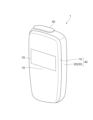
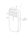
- FIG. 1A and 1B are overall perspective views of the aerosol generating device 1 in this embodiment.
- FIG. 1A shows an overall perspective view from diagonally above
- FIG. 1B shows an overall perspective view from diagonally below.
- the aerosol generating device 1 includes a front cover 10, a main body housing 20 to which the front cover 10 can be attached and detached, and a shutter 50.
- the front cover 10 and the main body housing 20 are configured as separate members.
- the front cover 10 includes a display window 60 and a display device 70 on its surface.
- the front cover 10 may be configured with different patterns and colors on the outer surface and different materials for each type of front cover. A user may appropriately select a type of front cover that suits his or her preference.
- the main body housing 20 accommodates the main body 30 of the aerosol generating device 1.
- the main body housing 20 also includes an external connection terminal 80 such as a USB (Universal Serial Bus) Type C connector.
- USB Universal Serial Bus
- the outermost housing 40 of the aerosol generating device 1 is formed by attaching the front cover 10 to the main housing 20.
- the fashionability of the aerosol generating device 1 can be improved by attaching a front cover 10 with a design that matches the user's preferences.
- the aerosol generating device 1 can buffer heat released to the outside even when the main body 30 generates heat.
- the front cover 10 functions to insulate heat generated from the heating section of the main body 30.
- the front cover 10 is formed so that its surface is approximately curved. Then, when attached to the main housing 20, the front cover 10 defines an internal space together with the surface of the main housing 20.
- the housing 40 should be sized to fit in the user's hand.
- the user holds the aerosol generating device 1 in one hand with the fingertips in contact with the surface of the front cover 10.
- the front cover 10 deforms to form a recess toward the main housing 20.
- a protrusion on the front cover 10 comes into contact with an operation button provided on the surface of the main housing 20, and the operation button is pressed down.
- the portion of the surface of the front cover 10 that is pressed with the fingertips forms the button area 15.
- the aerosol generating device 1 in this embodiment is advantageous in that it can prevent unintended erroneous operation by the user, including the accidental pressing of an operation button in a bag.
- the button area 15 of the front cover 10 cannot be easily pressed with the pressing force of a child that is inappropriate for the user of the aerosol generating device 1, so it is also advantageous in terms of preventing tampering (child resistance).
- the main housing 20 has an opening into which the stick-shaped substrate is inserted, but in Figures 1A and 1B, the shutter 50 is shown closing the opening.
- the shutter 50 has a sliding mechanism and can move along the surface of the outer shell between a first position that closes the opening and a second position that opens the opening.
- the opening and closing of the opening can be detected by providing a sensor (not shown) near the first position and/or the second position. For example, a magnet is placed in the shutter 50, and the opening and closing of the opening is detected by a magnetic sensor.
- the user places their finger on the shutter 50 and slides it along the side, opening the opening. With the opening open, the user can insert the stick-shaped substrate. After inserting the stick-shaped substrate, the user can press the surface of the front cover 10 with their finger and press the operation button to power on the aerosol generating device 1.
- the display window 60 is made of a transparent material and allows light from one or more LEDs (Light Emitting Diodes) arranged within the main body 30 to pass therethrough, as described below.
- the display device 70 is, for example, a liquid crystal display, an organic EL (Electro Luminescence) display, or the like, provided at a position not overlapping the display window 60.
- the display device 70 displays status information and the like of the main body 30 in the form of characters and images.
- the display device 70 may be a non-transparent display or a transparent display.
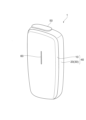
- FIG. 2A and 2B are overall perspective views of another example of the aerosol generating device 1 in this embodiment.
- FIG. 2A shows an overall perspective view from diagonally above
- FIG. 2B shows an overall perspective view from diagonally below.
- the display device 70 is provided in a position on the front cover 10 that does not overlap the display window 60, but in FIG. 2A and FIG. 2B, the display device 70 is provided in a position on the front cover 10 that overlaps the display window 60.
- the display device 70 is a non-transparent display. In this case, even if light from the LED passes through the display window 60, the user cannot see the light, so the display window 60 does not need to be provided.
- the display device 70 is a transparent display, the user can see the light from the LED that passes through the display window 60, so the display window 60 may be provided.
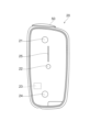
- FIG. 3A shows an external view of the inner surface of the front cover 10
- Fig. 3B shows an external view of the outer surface of the main body housing 20.
- magnet 11, protrusion 12, magnet 13, and magnet 14 are arranged along the longitudinal direction on the inner surface of front cover 10.
- front cover 10 is attached to main body housing 20, magnet 11 and magnet 14 are attracted to main body housing 20 by their magnetic force (magnetic attraction). This holds front cover 10 to main body housing 20.
- Protrusion 12 presses operation button 22 provided on the surface of main body housing 20.
- Magnet 13 is configured as a magnetic field application unit for the sensor unit of main body 30. In other words, the magnetic field applied by magnet 13 is detected by magnetic sensor 23 of main body housing 20, thereby detecting front cover 10.
- the magnet 21, the passage hole 25, the operation button 22, and the magnet 24 are arranged on the outer surface of the main housing 20 along the longitudinal direction from the shutter 50 side. Also, on the inner surface of the main housing 20 (more precisely, on a substrate that is approximately zero distance from the inner surface), a magnetic sensor 23 is arranged at a position between the operation button 22 and the magnet 24 along the longitudinal direction.
- the magnet 21, the operation button 22, the magnetic sensor 23, and the magnet 24 of the main housing 20 correspond to the magnet 11, the protrusion 12, the magnet 13, and the magnet 14 of the front cover 10, respectively. In other words, when the front cover 10 is attached to the main housing 20, the magnet 21, the operation button 22, the magnetic sensor 23, and the magnet 24 are aligned and face the magnet 11, the protrusion 12, the magnet 13, and the magnet 14, respectively.
- the magnets 21 and 24 of the main housing 20 are attracted to the magnets 11 and 14 of the front cover 10, respectively, by their magnetic force (magnetic attraction). In other words, the magnets 11 and 21, and the magnets 14 and 24 attract each other, thereby holding the front cover 10 in a mountable state to the main housing 20. It is preferable that the magnets 11 and 14 of the front cover 10, and the magnets 21 and 24 of the main housing 20 are made of permanent magnets.
- the operation button 22 is provided on the surface to which the front cover 10 is attached. In other words, when the front cover 10 is attached to the main body housing 20, the operation button 22 is covered by the front cover 10 and pressed by the protrusion 12 of the front cover 10. This allows, for example, the aerosol generating device 1 to be switched on and off.
- the magnetic sensor 23 detects the magnetic force based on the magnetic field applied from the magnet 13 in the front cover 10.
- the magnetic sensor 23 is preferably a Hall sensor configured using a Hall element. This makes it possible to detect the attachment of the front cover 10 to the main body housing 20.
- the magnetic sensor 23 of the main housing 20 is positioned so as to face the magnet 13 of the front cover 10 via the inner surface of the main housing 20 when the front cover 10 is attached to the main housing 20. In other words, when the front cover 10 is attached to the main housing 20, the distance between the magnetic sensor 23 of the main housing 20 and the magnet 13 of the front cover 10 is minimized.
- the magnetic sensor 23 of the main housing 20 is configured so as not to detect the magnetic fields generated by the two magnets 21 and magnet 24 of the main housing 20. Specifically, it is preferable to position the magnetic sensor 23 on the inner surface of the main housing 20 at a position spaced apart from the two magnets 21 and magnet 24 on the outer surface of the main housing 20. This makes it possible to reduce the influence of the magnetic fields from the two magnets 21 and magnet 24 on the magnetic sensor 23 to approximately zero.
- the distance between the magnetic sensor 23 and the magnet 24 (or magnet 21) in the main housing 20 is greater than the distance between the magnet 13 and the magnetic sensor 23 when the front cover 10 is attached to the main housing 20. This allows the magnetic sensor 23 to appropriately take into account only the effect of the magnetic field applied from the magnet 13, without taking into account the effect of the magnetic field of the magnet 24, when detecting the attachment of the front cover 10 to the main housing 20.
- the through hole 25 is an opening aligned with one or more LEDs arranged in the main body 30, and allows light from the LEDs to pass through to the display window 60 of the front cover 10. This allows the user to see the light from the outer surface of the front cover 10.
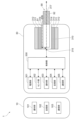
- FIG. 4 is a schematic diagram showing an example of the internal configuration of the aerosol generating device 1.
- a stick-type substrate 90 having an aerosol source which is a source of inhaled components, and a flavor generating substrate such as a filling containing a flavor source is inserted.
- the aerosol source is not limited to a liquid, and may be a solid.
- the inserted stick-type substrate 90 generates an aerosol containing a flavor by being heated from its outer periphery.
- the front cover 10 includes a notification unit 101, a memory unit 102, and a communication unit 103.
- the notification unit 101 notifies the user of information.
- the notification unit 101 is a display device 70 such as a liquid crystal display or an organic electroluminescence display, but it may also be a sound output device that outputs sound, a vibration device that vibrates, etc.
- the notification unit 101 may notify information by a notification means different from the notification unit 303 of the main body 30, so long as it notifies information in more detail than the notification unit 303 of the main body 30.
- the notification unit 303 of the main body 30 is an LED
- the notification unit 101 may notify information in more detail than the LED by using multiple vibration patterns.
- the notification unit 101 is an example of a detailed display unit that displays in detail.
- the memory unit 102 stores information about the front cover 10.
- the information about the front cover 10 includes information indicating whether the front cover 10 has a display device 70. Furthermore, if the front cover 10 has the display device 70, the information about the front cover 10 includes information indicating the position of the display device 70 on the front cover 10 and information indicating whether the display device 70 is a transparent display or a non-transparent display.
- the communication unit 103 employs NFC (Near field communication) as the short-range wireless communication standard
- the memory unit 102 is realized by the memory function of an NFC tag.
- An NFC tag is a tag that includes an antenna for communication using NFC and an IC (Integrated Circuit) chip that performs processing for communication using NFC.
- the memory unit 102 may be realized by a ROM (Read Only Memory).
- the communication unit 103 is a communication interface capable of performing communication conforming to any short-range wireless communication standard.
- Such short-range wireless communication standards may include NFC and Bluetooth (registered trademark).
- NFC is used as the short-range wireless communication standard
- the communication unit 103 is realized by the communication function of an NFC tag.
- the communication unit 103 may perform communication by, for example, mechanical contact of electrodes, mechanical contact by spring-loaded electrode pins (pogo pins), or by coupling of a connector.
- the main body 30 also includes a control unit 300, a power supply unit 301, a sensor unit 302, a notification unit 303, a memory unit 304, a communication unit 305, a holding unit 310, a heating unit 311, and a heat insulating unit 312.
- the control unit 300 functions as an arithmetic processing device and control device, and controls the overall operation of the aerosol generating device 1 in accordance with various programs.
- the control unit 300 is realized by electronic circuits such as a CPU (Central Processing Unit) and a microprocessor.
- the power supply unit 301 stores power.
- the power supply unit 301 supplies power to each component of the aerosol generating device 1 based on the control by the control unit 300.
- the power supply unit 301 may be configured, for example, by a rechargeable battery such as a lithium ion secondary battery.
- the sensor unit 302 acquires various information related to the aerosol generating device 1.
- the sensor unit 302 is configured with a pressure sensor such as a microphone capacitor, a flow sensor, or a temperature sensor, and acquires values associated with inhalation by the user.
- the sensor unit 302 is configured with an input device such as a button or switch that accepts information input from the user.
- the sensor unit 302 also detects the attachment of the front cover 10 to the main body housing 20.
- the sensor unit 302 is configured with a magnetic sensor 23.
- the sensor unit 302 detects that the front cover 10, which has a magnetic field application unit (e.g., a magnet and/or a magnetic material) that applies a magnetic field to the magnetic sensor 23, is in the vicinity of the sensor unit 302.
- a magnetic field application unit e.g., a magnet and/or a magnetic material
- the notification unit 303 notifies the user of information.
- the notification unit 303 is a display unit made up of light-emitting elements such as LEDs, but it may also be a sound output device that outputs sound, a vibration device that vibrates, etc.
- the notification unit 303 may notify information by a notification means different from the notification unit 101 of the front cover 10, so long as it notifies information more easily than the notification unit 101 of the front cover 10.
- the notification unit 101 of the front cover 10 is a liquid crystal display, it may notify information more easily than a liquid crystal display by using a small number of vibration patterns.
- the notification unit 303 is an example of a simple display unit that displays information simply.
- the LED notifies the user of the operating information of the aerosol generating device 1 by emitting light in a predetermined manner. Specifically, the LED emits light to notify the user of the status of whether the aerosol generating device 1 is turned on, the progress of pre-heating, the suction status (remaining time available for suction, etc.), and the current operating mode of the aerosol generating device 1 (for example, suction mode and/or communication mode, etc.).
- the storage unit 304 stores various information for the operation of the aerosol generating device 1.
- the storage unit 304 is composed of a non-volatile storage medium such as a flash memory.
- the storage unit 304 also stores programs such as firmware in addition to computer-executable instructions for operating the aerosol generating device 1.
- the communication unit 305 is a communication interface capable of performing communication conforming to any wired or wireless communication standard.
- wireless communication for example, Wi-Fi (registered trademark) or Bluetooth (registered trademark) may be adopted as such a communication standard.
- wired communication for example, a data communication cable is connected via the external connection terminal 80. This allows input/output of data related to the operation of the aerosol generating device 1 between the external device.
- the communication unit 305 may activate its communication function when the opening 314 of the shutter 50 is opened, and start communication with an external terminal using Bluetooth (registered trademark) or the like. Also, when the opening 314 of the shutter 50 is closed, communication with the external terminal that is currently communicating may be terminated. It is particularly preferable that the Bluetooth (registered trademark) connection between the communication unit 305 and the external terminal be a connection using BLE (Bluetooth Low Energy).
- BLE Bluetooth Low Energy
- the communication unit 305 is also a communication interface capable of communicating with the front cover 10 in accordance with any short-range wireless communication standard.
- short-range wireless communication standards may include NFC and Bluetooth (registered trademark).
- the communication unit 305 may communicate by, for example, mechanical contact of electrodes, mechanical contact using spring-loaded electrode pins (pogo pins), or by connecting a connector.
- the holding part 310 has an internal space 313, and holds the stick-shaped substrate 90 while accommodating a portion of the stick-shaped substrate 90 in the internal space 313.
- the holding part 310 has an opening 314 that connects the internal space 313 to the outside, and holds the stick-shaped substrate 90 inserted into the internal space 313 through the opening 314.
- the holding part 310 is a cylindrical body with the opening 314 and the bottom part 315 as its bottom surface, and defines a columnar internal space 313.
- the direction in which the stick-shaped substrate 90 is inserted into the internal space 313 is defined as the longitudinal direction of the aerosol generation device 1.
- the holding part 310 has a pressing part and a non-pressing part (neither shown) along the longitudinal direction on the inner wall of the internal space 313.
- the pressing part presses the stick-shaped substrate 90 in a direction perpendicular to the longitudinal direction.
- the stick-shaped substrate 90 is then clamped by the holding part 310 while being pressed and deformed by the pressing part.
- the stick-shaped substrate 90 is heated from the outer periphery by the heating part 311 while being pressed.
- a gap (not shown) is formed between the non-pressure portion and the stick-shaped substrate 90. This allows the opening 314 and the bottom 315 to communicate with each other through the gap.
- the holding portion 310 also has the function of defining a flow path for air to be supplied to the stick-shaped substrate 90.
- the air inlet hole 316 which is the entrance of air to this flow path, is the opening 314. More precisely, the air inlet hole 316 is the gap between the non-pressure portion and the stick-shaped substrate 90. The air that flows in from the air inlet hole 316 when the user inhales is transported along the dotted arrow through the stick-shaped substrate 90 to the air outlet hole 317, which is the exit for air from the flow path.
- the stick-type substrate 90 includes a substrate portion 91 and a suction mouth portion 92.
- the substrate portion 91 includes an aerosol source.
- the stick-type substrate 90 is held by the holder 310, at least a portion of the substrate portion 91 is contained in the internal space 313, and at least a portion of the suction mouth portion 92 protrudes from the opening 314.
- the user holds the suction mouth portion 92 protruding from the opening 314 in his/her mouth and inhales, air flows into the internal space 313 from the air inlet hole 316, and is transported to the air outlet hole 317 of the suction mouth portion 92 via the bottom portion 315 along the dotted arrow, and reaches the user's oral cavity together with the aerosol generated from the substrate portion 91.
- the stick-type substrate 90 is an example of a substrate that includes an aerosol source.
- the heating unit 311 generates aerosol by heating the aerosol source and atomizing the aerosol source.
- the heating unit 311 is configured in a film shape and is arranged to cover the outer periphery of the holding unit 310.
- the heating unit 311 generates heat, the substrate unit 91 of the stick-shaped substrate 90 is heated from the outer periphery, and an aerosol is generated.
- the heating unit 311 generates heat when power is supplied from the power supply unit 301.
- power may be supplied when the sensor unit 302 detects that the user has started inhaling, that a specific user input operation has been received, and/or that specific information has been input.
- the heating unit 311 is an example of a heating unit that heats the substrate by power supply from a power source.
- the insulating section 312 prevents heat transfer from the heating section 311 to other components.
- the insulating section 312 is made of a vacuum insulating material, an aerogel insulating material, or the like.
- the configuration of the aerosol generating device 1 is not limited to the above, and various configurations such as those exemplified below are possible.
- the heating unit 311 may be configured in a blade shape and disposed so as to protrude from the bottom 315 of the holding unit 310 into the internal space 313.
- the blade-shaped heating unit 311 is inserted into the substrate 91 of the stick-shaped substrate 90 and heats the substrate 91 of the stick-shaped substrate 90 from the inside.
- the heating unit 311 may be disposed so as to cover the bottom 315 of the holding unit 310.
- the heating unit 311 may also be configured as a combination of two or more of a first heating unit that covers the outer periphery of the holding unit 310, a blade-shaped second heating unit, and a third heating unit that covers the bottom 315 of the holding unit 310.
- the means for atomizing the aerosol source is not limited to heating by the heating unit 311.
- the means for atomizing the aerosol source may be induction heating.
- the control unit 300 performs the following first to third display controls.
- a liquid crystal display will be taken as an example of the notification unit 101 of the front cover 10
- an LED will be taken as an example of the notification unit 303 of the main body 30.
- the control unit 300 performs a first display control in which, when the front cover 10 is not attached, an LED display is performed, and when the front cover 10 is attached, the control unit 300 determines whether or not to display an LED display depending on the type of front cover 10.
- the control unit 300 also performs a second display control when the types of front cover 10 include a first front cover having a liquid crystal display and a second front cover not having a liquid crystal display. Specifically, as the second display control, the control unit 300 performs display control such that when the first front cover is attached, no LED display is performed, and when the second front cover is attached, LED display is performed.
- control unit 300 performs a third display control when the first front cover includes a third front cover that hides the LED when attached, and a fourth front cover that does not hide the LED even when attached.
- the aerosol generating device 1 performs the third display control by not displaying using the LED when the third front cover is attached, and by displaying using the LED when the fourth front cover is attached.
- FIG. 5 is a diagram showing a display example of the aerosol generating device 1 in this case.
- FIG. 5 shows an external view of the outer surface of the main body housing 20, similar to FIG. 3B.
- a through hole 25 is provided on the outer surface of the main body housing 20.
- the through hole 25 allows light from an LED arranged in the main body 30 to pass through.
- the aerosol generating device 1 performs display using the LED, as shown by dot hatching in the through hole 25 in the figure.
- performing display using the LED includes making the LED displayable when there is no information to be displayed at that time, so that when information to be displayed is generated, the LED is displayed. For example, when the front cover 10 is not attached, the aerosol generating device 1 keeps the LED switch on.
- FIG. 6 is a diagram showing a display example of the aerosol generation device 1 in this case.
- FIG. 6 shows an overall perspective view of the aerosol generation device 1 from diagonally above, similar to FIG. 1A.
- a display window 60 is provided on the outer surface of the front cover 10.
- the display window 60 allows light from an LED arranged in the main body 30 to pass through.
- the aerosol generation device 1 performs display using an LED, as shown by dot hatching in the display window 60 in the figure.
- performing display using an LED includes making the LED displayable so that when there is no information to be displayed at that time, the LED displays when information to be displayed is generated.
- the aerosol generation device 1 keeps the LED switch on even when a front cover 10 without a liquid crystal display is attached.
- FIG. 7 is a diagram showing a display example of the aerosol generation device 1 in this case. Like FIG. 1A, FIG. 7 also shows an overall perspective view of the aerosol generation device 1 from diagonally above.
- a display device 70 is provided on the outer surface of the front cover 10 at a position overlapping the display window 60.
- the display device 70 is a non-transparent liquid crystal display here. That is, the display device 70 hides the display window 60 and also hides the passage hole 25.
- the aerosol generation device 1 performs display using a liquid crystal display, as shown by hatching in the display device 70 in the figure.
- the aerosol generation device 1 does not perform display using the LED.
- not performing display using the LED includes putting the LED in a state where it cannot be displayed so that no display using the LED is performed even if information to be displayed is generated when there is no information to be displayed at that time.
- the aerosol generation device 1 turns off the LED switch when the front cover 10 that hides the LED by being attached is attached.
- the display device 70 is provided at a position overlapping the display window 60 of the front cover 10, so that the front cover 10 hides the LED, but this is not limited to the above. Even if the display device 70 is not provided at a position overlapping the display window 60 of the front cover 10, the front cover 10 may hide the LED by not providing a display window 60 in the front cover 10.
- FIG. 8 is a diagram showing a first display example of the aerosol generation device 1 in this case.
- FIG. 8 also shows an overall perspective view of the aerosol generation device 1 from diagonally above, as in FIG. 1A.
- a display window 60 is provided on the outer surface of the front cover 10, and a display device 70 is provided at a position that does not overlap the display window 60.
- the display window 60 allows light from an LED arranged in the main body 30 to pass through, and the display device 70 is a non-transparent liquid crystal display here.
- the aerosol generation device 1 performs display using a liquid crystal display, as shown by hatching in the display device 70 in the figure.
- the aerosol generation device 1 also performs display using an LED, as shown by hatching in the display window 60 in the figure.
- performing display using an LED includes making the LED displayable when there is no information to be displayed at that time, so that when information to be displayed is generated, the LED is displayed.
- the aerosol generation device 1 keeps the LED switch on even when a front cover 10 that does not hide the LED is attached.
- FIG. 9 is a diagram showing a second display example of the aerosol generation device 1.
- the aerosol generation device 1 performs display using a liquid crystal display, as shown by hatching in the display device 70 in the figure.
- the aerosol generation device 1 performs display control different from the third display control, and does not perform display using LEDs, as shown by not hatching in the display window 60 in the figure.
- not performing display using LEDs includes putting the LEDs in a state where they cannot be displayed, so that LEDs are not displayed even if information to be displayed is generated, when there is no information to be displayed at that time.
- the aerosol generation device 1 turns off the LED switch when a front cover 10 that does not hide the LEDs even when attached is attached.
- the display device 70 is provided in a position that does not overlap the display window 60 of the front cover 10 so that the front cover 10 does not hide the LEDs, but this is not limited to the above. Even if the display device 70 is provided in a position that overlaps the display window 60 of the front cover 10, the front cover 10 may not hide the LEDs by making the display device 70 a transparent display.
- the first operation example is an operation example in which the display in Fig. 8 is performed when the front cover 10 that does not hide the LED even when attached is attached.
- the first operation example is an operation example in which all of the first display control, the second display control, and the third display control are performed.
- the second operation example is an operation example in which the display of Fig. 9 is performed when a front cover 10 that does not hide the LED even when attached is attached.
- This second operation example can be considered as an operation example in which, when a front cover 10 having a liquid crystal display is attached, the LED is not displayed regardless of whether the liquid crystal display hides the LED.
- the second operation example is an operation example in which the first display control and the second display control are performed, and the third display control is not performed.
- FIG. 10 is a flowchart showing a first example of the operation of the control unit 300 of the aerosol generating device 1 in this embodiment.
- the control unit 300 determines whether the front cover 10 is attached (step 351). For example, the control unit 300 determines whether the front cover 10 is attached based on whether the magnetic sensor 23 detects the magnetic force from the magnet 13 of the front cover 10. If it is determined that the front cover 10 is not attached, the control unit 300 controls the LED to display (step 354). For example, the control unit 300 turns on the LED switch so that the LED can display.
- the control unit 300 determines whether the front cover 10 has a liquid crystal display (step 352). For example, the control unit 300 receives information indicating whether the front cover 10 has a liquid crystal display, which is stored in the memory unit 102 of the front cover 10, from the communication unit 103 of the front cover 10 via the communication unit 305. The control unit 300 then determines whether the front cover 10 has a liquid crystal display based on this received information. If it is determined here that the front cover 10 does not have a liquid crystal display, the control unit 300 controls the LED to display (step 354). For example, the control unit 300 turns on the LED switch so that the LED can be used for display.
- the control unit 300 determines whether the liquid crystal display hides the LED (step 353). For example, the control unit 300 receives information indicating the position of the liquid crystal display and information indicating whether the liquid crystal display is transparent or non-transparent, which are stored in the memory unit 102 of the front cover 10, from the communication unit 103 of the front cover 10 via the communication unit 305. Then, based on this received information, the control unit 300 determines whether the liquid crystal display hides the LED. If it is determined here that the liquid crystal display does not hide the LED, the control unit 300 controls the LED to be displayed (step 354). For example, the control unit 300 turns on the LED switch so that the LED can be displayed.
- step 353 If it is determined in step 353 that the LCD display hides the LED, the control unit 300 controls the LED so that it is not displayed (step 355). For example, the control unit 300 turns off the LED switch so that display by the LED is not possible. At that time, the control unit 300 controls the LCD display so that it is displayed.
- step 353 if it is determined in step 353 that the LCD display does not hide the LED, the control unit 300 controls the LED to be displayed, but this is not limited to the above. Even if it is determined in step 353 that the LCD display does not hide the LED, if it is determined that the front cover 10 hides the LED because the display window 60 is not provided or for other reasons, the control unit 300 may control the LED not to be displayed.
- FIG. 11 is a flowchart showing a second operation example of the control unit 300 of the aerosol generating device 1 in this embodiment.
- the flowchart in FIG. 11 is obtained by removing step 353 from the flowchart in FIG. 10.
- steps 351, 352, 354, and 355 in FIG. 10 are respectively steps 371, 372, 373, and 374 in FIG. 11.
- the control unit 300 controls the LED to display (step 373). For example, the control unit 300 turns on the LED switch so that display by the LED is possible. If it is determined in step 372 that the front cover 10 has a liquid crystal display, the control unit 300 controls the LED not to display (step 374). For example, the control unit 300 turns off the LED switch so that display by the LED is disabled. At that time, the control unit 300 controls the liquid crystal display to display.
- the present embodiment has been described as being applied to a heated tobacco product, but is not limited thereto.
- the present embodiment is applied to various aerosol generating devices for inhaling aerosol, such as electronic cigarettes and nebulizers.
- the generated inhaled components may include gases such as invisible steam in addition to aerosols.
- the present embodiment may be applied to general electronic devices other than aerosol generating devices.
- An electronic device comprising a simplified display unit that provides simplified display and a control unit that controls the simplified display unit to display when a cover is not attached, and the control unit determines whether or not to display on the simplified display unit when a cover is attached, depending on the type of cover.
- the types of covers include a first cover having a detailed display section that displays in detail and a second cover that does not have a detailed display section, and the control section controls the electronic device so that no display is performed using the simplified display section when the first cover is attached, and that no display is performed using the simplified display section when the second cover is attached.
- the electronic device according to (2), wherein the first cover is a cover that hides the simple display unit when attached.
- the control unit sets the simplified display unit to a display disabled state when the first cover is attached.
- An aerosol generating device comprising a heating unit that heats a substrate containing an aerosol source by power supply from a power source, a simple display unit that provides a simple display, and a control unit that controls the simple display unit to display when a cover is not attached, wherein the control unit determines whether or not to display on the simple display unit when a cover is attached, depending on the type of cover.
- 1...aerosol generating device 10...front cover, 20...main body housing, 30...main body, 40...housing, 50...shutter, 60...display window, 70...display device, 80...external connection terminal, 101...notification unit, 102...storage unit, 103...communication unit, 300...control unit, 301...power supply unit, 302...sensor unit, 303...notification unit, 304...storage unit, 305...communication unit, 310...holding unit, 311...heating unit, 312...insulation unit
Landscapes
- Engineering & Computer Science (AREA)
- Human Computer Interaction (AREA)
- Containers And Packaging Bodies Having A Special Means To Remove Contents (AREA)
Abstract
Description
特許文献2には、制御部が、非通常状態の内容や原因に基づいたエラー信号を生成し、通知部に、エラー信号に応じた通知をさせるエアロゾル生成装置が開示されている。そして、通知部は、例えば、発光ダイオードであることが記載されている。
カバーの種別は、詳細に表示を行う詳細表示部を有する第1のカバーと、詳細表示部を有しない第2のカバーとを含み、制御部は、第1のカバーが装着されている場合に簡易表示部による表示を行わず、第2のカバーが装着されている場合に簡易表示部による表示を行うように制御する、ものであってよい。
その場合、第1のカバーは、装着されることにより簡易表示部を隠すカバーであってもよいし、装着されても簡易表示部を隠さないカバーであってもよい。
その場合、制御部は、第1のカバーが装着された際に簡易表示部を表示不可能な状態とする、ものであってよい。
その場合、第1のカバーは、装着されることにより簡易表示部を隠す第3のカバーと、装着されても簡易表示部を隠さない第4のカバーとを含み、制御部は、第3のカバーが装着されている場合に簡易表示部による表示を行わず、第4のカバーが装着されている場合に簡易表示部による表示を行うように制御する、ものであってよい。また、その場合、制御部は、第3のカバーが装着された際に簡易表示部を表示不可能な状態とする、ものであってよい。
図1A及び図1Bは、本実施の形態におけるエアロゾル生成装置1の全体斜視図である。図1Aは、斜め上方からの全体斜視図を示し、図1Bは、斜め下方からの全体斜視図を示す。図示するように、エアロゾル生成装置1は、フロントカバー10と、フロントカバー10を着脱可能な本体ハウジング20と、シャッタ50とを備える。フロントカバー10及び本体ハウジング20は別部材で構成される。フロントカバー10は、その表面に表示窓60と表示装置70とを備える。尚、フロントカバー10は、フロントカバーの種別毎に、外側表面が異なる模様及び色彩によるデザイン、並びに異なる素材等によって構成されるのがよい。ユーザは自らの嗜好に合う種別のフロントカバーを適宜選択すればよい。本体ハウジング20は、エアロゾル生成装置1の本体30を収容する。また、本体ハウジング20は、USB(Universal Serial Bus)タイプCのコネクタ等の外部接続端子80を備える。
表示装置70は、表示窓60に重ならない位置に設けられた、例えば液晶ディスプレイ、有機EL(Electro Luminescence)ディスプレイ等である。表示装置70は、本体30の状態情報等を文字や画像で表示する。表示装置70は、非透明ディスプレイであっても、透明ディスプレイであってもよい。
図3A及び図3Bは、エアロゾル生成装置1のフロントカバー10及び本体ハウジング20の外観図である。図3Aはフロントカバー10の内側表面の外観図を示し、図3Bは本体ハウジング20の外側表面の外観図を示す。フロントカバー10が本体ハウジング20に取り付けられる状態で、フロントカバー10の内側表面と、本体ハウジング20の外側表面とが相互に対向する。
図4は、エアロゾル生成装置1の内部構成例を示す模式図である。エアロゾル生成装置1では、例えば、吸引成分源であるエアロゾル源及び香味源を含む充填物等の香味発生基材を有するスティック型基材90が挿入される。尚、エアロゾル源は液体に限られるものではなく、固体であってもよい。挿入されたスティック型基材90は、その外周から加熱されることによって、香味を含むエアロゾルを生成する。
以上のようなエアロゾル生成装置1において、本実施の形態では、制御部300が、次の第1乃至第3の表示制御を行う。尚、以下では、フロントカバー10の通知部101として液晶ディスプレイを例にとり、本体30の通知部303としてLEDを例にとって説明する。
まず、第1の表示制御における、フロントカバー10が装着されていない場合のエアロゾル生成装置1の表示例について説明する。
図5は、この場合のエアロゾル生成装置1の表示例について示した図である。図5は、図3Bと同様に、本体ハウジング20の外側表面の外観図を示している。本体ハウジング20の外側表面には、通過孔25が設けられている。通過孔25は、本体30内に配置されたLEDからの光を通過させるものである。エアロゾル生成装置1は、図中、通過孔25内にドットハッチングを施すことで示すように、LEDによる表示を行う。ここで、LEDによる表示を行うことは、その時点で表示すべき情報がない場合には、表示すべき情報が発生するとLEDによる表示を行うようにLEDを表示可能な状態とすることを含む。例えば、エアロゾル生成装置1は、フロントカバー10が装着されていない場合、LEDのスイッチをオンにしておく。
図6は、この場合のエアロゾル生成装置1の表示例について示した図である。図6は、図1Aと同様に、エアロゾル生成装置1の斜め上方からの全体斜視図を示している。フロントカバー10の外側表面には、表示窓60が設けられている。表示窓60は、本体30内に配置されたLEDからの光を通過させるものである。エアロゾル生成装置1は、図中、表示窓60内にドットハッチングを施すことで示すように、LEDによる表示を行う。ここで、LEDによる表示を行うことは、その時点で表示すべき情報がない場合には、表示すべき情報が発生するとLEDによる表示を行うようにLEDを表示可能な状態とすることを含む。例えば、エアロゾル生成装置1は、液晶ディスプレイを有しないフロントカバー10が装着されても、LEDのスイッチをオンのままとする。
図7は、この場合のエアロゾル生成装置1の表示例について示した図である。図7も、図1Aと同様に、エアロゾル生成装置1の斜め上方からの全体斜視図を示している。フロントカバー10の外側表面には、表示窓60に重なる位置に表示装置70が設けられている。表示装置70は、ここでは、非透明な液晶ディスプレイである。つまり、表示装置70は、表示窓60を隠し、通過孔25も隠している。エアロゾル生成装置1は、図中、表示装置70内に斜線ハッチングを施すことで示すように、液晶ディスプレイによる表示を行う。一方、通過孔25が隠れており、LEDからの光を外部から視認できないため、エアロゾル生成装置1は、LEDによる表示を行わない。ここで、LEDによる表示を行わないことは、その時点で表示すべき情報がない場合には、表示すべき情報が発生してもLEDによる表示を行わないようにLEDを表示不可能な状態とすることを含む。例えば、エアロゾル生成装置1は、装着されることによりLEDを隠すフロントカバー10が装着された際に、LEDのスイッチをオフにする。
図8は、この場合のエアロゾル生成装置1の第1の表示例について示した図である。図8も、図1Aと同様に、エアロゾル生成装置1の斜め上方からの全体斜視図を示している。フロントカバー10の外側表面には、表示窓60が設けられ、表示窓60に重ならない位置に表示装置70が設けられている。表示窓60は、本体30内に配置されたLEDからの光を通過させるものであり、表示装置70は、ここでは、非透明な液晶ディスプレイである。エアロゾル生成装置1は、図中、表示装置70内に斜線ハッチングを施すことで示すように、液晶ディスプレイによる表示を行う。また、エアロゾル生成装置1は、図中、表示窓60内にドットハッチングを施すことで示すように、LEDによる表示も行う。ここで、LEDによる表示を行うことは、その時点で表示すべき情報がない場合には、表示すべき情報が発生するとLEDによる表示を行うようにLEDを表示可能な状態とすることを含む。例えば、エアロゾル生成装置1は、装着されてもLEDを隠さないフロントカバー10が装着されても、LEDのスイッチをオンのままとする。
図9は、エアロゾル生成装置1の第2の表示例について示した図である。エアロゾル生成装置1は、図8と同様、図中、表示装置70内に斜線ハッチングを施すことで示すように、液晶ディスプレイによる表示を行う。一方、第3の表示制御とは異なる表示制御となるが、エアロゾル生成装置1は、図中、表示窓60内にドットハッチングを施さないことで示すように、LEDによる表示を行わない。ここで、LEDによる表示を行わないことは、その時点で表示すべき情報がない場合には、表示すべき情報が発生してもLEDによる表示を行わないようにLEDを表示不可能な状態とすることを含む。例えば、エアロゾル生成装置1は、装着されてもLEDを隠さないフロントカバー10が装着された際に、LEDのスイッチをオフにする。
本実施の形態におけるエアロゾル生成装置1の制御部300の動作例としては、第1の動作例と、第2の動作例とが考えられる。
第1の動作例は、装着されてもLEDを隠さないフロントカバー10が装着されている場合に図8の表示を行う動作例である。換言すれば、第1の動作例は、第1の表示制御、第2の表示制御、及び第3の表示制御の全てを行う場合の動作例である。
第2の動作例は、装着されてもLEDを隠さないフロントカバー10が装着されている場合に図9の表示を行う動作例である。この第2の動作例は、液晶ディスプレイを有するフロントカバー10が装着されている場合に、液晶ディスプレイがLEDを隠すかどうかに関わらずLEDを表示しない、という動作例と捉えることができる。換言すれば、第2の動作例は、第1の表示制御及び第2の表示制御を行い、第3の表示制御を行わない場合の動作例である。
ステップ372の判定処理の内容は、図10のステップ352の判定処理の内容と同じである。
ステップ372でフロントカバー10が液晶ディスプレイを有しないと判定すれば、制御部300は、LEDを表示するように制御する(ステップ373)。例えば、制御部300は、LEDによる表示が可能となるように、LEDのスイッチをオンにする。
ステップ372でフロントカバー10が液晶ディスプレイを有すると判定すれば、制御部300は、LEDを表示しないように制御する(ステップ374)。例えば、制御部300は、LEDによる表示が不可能となるように、LEDのスイッチをオフにする。その際、制御部300は、液晶ディスプレイを表示するように制御する。
上記では、本実施の形態を加熱式たばこに適用した場合について説明したが、これには限らない。本実施の形態は、電子たばこやネブライザ等、エアロゾルを吸引するための様々なエアロゾル生成装置に適用される。また、生成される吸引成分は、エアロゾル以外にも、不可視の蒸気のような気体も含み得る。更に、本実施の形態は、エアロゾル生成装置以外の一般の電子機器に適用してもよい。
本実施の形態におけるエアロゾル生成装置1では、フロントカバー10が装着されていない場合には、LEDによる表示を行い、フロントカバー10が装着されている場合には、フロントカバー10の種別に応じて、LEDによる表示の有無を決定するようにした。これにより、本実施の形態では、フロントカバー10が装着されている場合にフロントカバー10の種別に関わらずLEDによる表示を行うことによる電力の無駄を軽減することが可能となった。
本開示は、以下の構成を含む。
(1)簡易に表示を行う簡易表示部と、カバーが装着されていない場合に簡易表示部による表示を行うように制御する制御部と、を備え、制御部は、カバーが装着されている場合に、カバーの種別に応じて、簡易表示部による表示の有無を決定する、電子機器。
(2)カバーの種別は、詳細に表示を行う詳細表示部を有する第1のカバーと、詳細表示部を有しない第2のカバーとを含み、制御部は、第1のカバーが装着されている場合に簡易表示部による表示を行わず、第2のカバーが装着されている場合に簡易表示部による表示を行うように制御する、(1)に記載の電子機器。
(3)第1のカバーは、装着されることにより簡易表示部を隠すカバーである、(2)に記載の電子機器。
(4)第1のカバーは、装着されても簡易表示部を隠さないカバーである、(2)に記載の電子機器。
(5)制御部は、第1のカバーが装着された際に簡易表示部を表示不可能な状態とする、(2)乃至(4)の何れか1つに記載の電子機器。
(6)第1のカバーは、装着されることにより簡易表示部を隠す第3のカバーと、装着されても簡易表示部を隠さない第4のカバーとを含み、制御部は、第3のカバーが装着されている場合に簡易表示部による表示を行わず、第4のカバーが装着されている場合に簡易表示部による表示を行うように制御する、(2)乃至(5)の何れか1つに記載の電子機器。
(7)制御部は、第3のカバーが装着された際に簡易表示部を表示不可能な状態とする、(6)に記載の電子機器。
(8)電源からの給電によりエアロゾル源を含む基材を加熱する加熱部と、簡易に表示を行う簡易表示部と、カバーが装着されていない場合に簡易表示部による表示を行うように制御する制御部と、を備え、制御部は、カバーが装着されている場合に、カバーの種別に応じて、簡易表示部による表示の有無を決定する、エアロゾル生成装置。
Claims (8)
- 簡易に表示を行う簡易表示部と、
カバーが装着されていない場合に前記簡易表示部による表示を行うように制御する制御部と、
を備え、
前記制御部は、前記カバーが装着されている場合に、当該カバーの種別に応じて、前記簡易表示部による表示の有無を決定する、
電子機器。 - 前記カバーの種別は、詳細に表示を行う詳細表示部を有する第1のカバーと、当該詳細表示部を有しない第2のカバーとを含み、
前記制御部は、前記第1のカバーが装着されている場合に前記簡易表示部による表示を行わず、前記第2のカバーが装着されている場合に前記簡易表示部による表示を行うように制御する、
請求項1に記載の電子機器。 - 前記第1のカバーは、装着されることにより前記簡易表示部を隠すカバーである、
請求項2に記載の電子機器。 - 前記第1のカバーは、装着されても前記簡易表示部を隠さないカバーである、
請求項2に記載の電子機器。 - 前記制御部は、前記第1のカバーが装着された際に前記簡易表示部を表示不可能な状態とする、
請求項2乃至請求項4の何れか1項に記載の電子機器。 - 前記第1のカバーは、装着されることにより前記簡易表示部を隠す第3のカバーと、装着されても前記簡易表示部を隠さない第4のカバーとを含み、
前記制御部は、前記第3のカバーが装着されている場合に前記簡易表示部による表示を行わず、前記第4のカバーが装着されている場合に前記簡易表示部による表示を行うように制御する、
請求項2乃至請求項5の何れか1項に記載の電子機器。 - 前記制御部は、前記第3のカバーが装着された際に前記簡易表示部を表示不可能な状態とする、
請求項6に記載の電子機器。 - 電源からの給電によりエアロゾル源を含む基材を加熱する加熱部と、
簡易に表示を行う簡易表示部と、
カバーが装着されていない場合に前記簡易表示部による表示を行うように制御する制御部と、
を備え、
前記制御部は、前記カバーが装着されている場合に、当該カバーの種別に応じて、前記簡易表示部による表示の有無を決定する、
エアロゾル生成装置。
Priority Applications (5)
| Application Number | Priority Date | Filing Date | Title |
|---|---|---|---|
| CN202280102506.6A CN120282724A (zh) | 2022-12-12 | 2022-12-12 | 电子装置和气溶胶产生装置 |
| PCT/JP2022/045667 WO2024127459A1 (ja) | 2022-12-12 | 2022-12-12 | 電子機器及びエアロゾル生成装置 |
| KR1020257018961A KR20250094730A (ko) | 2022-12-12 | 2022-12-12 | 전자 기기 및 에어로졸 생성 장치 |
| JP2024563779A JPWO2024127459A1 (ja) | 2022-12-12 | 2022-12-12 | |
| EP22968371.9A EP4635345A1 (en) | 2022-12-12 | 2022-12-12 | Electronic device and aerosol generation device |
Applications Claiming Priority (1)
| Application Number | Priority Date | Filing Date | Title |
|---|---|---|---|
| PCT/JP2022/045667 WO2024127459A1 (ja) | 2022-12-12 | 2022-12-12 | 電子機器及びエアロゾル生成装置 |
Publications (1)
| Publication Number | Publication Date |
|---|---|
| WO2024127459A1 true WO2024127459A1 (ja) | 2024-06-20 |
Family
ID=91484494
Family Applications (1)
| Application Number | Title | Priority Date | Filing Date |
|---|---|---|---|
| PCT/JP2022/045667 Ceased WO2024127459A1 (ja) | 2022-12-12 | 2022-12-12 | 電子機器及びエアロゾル生成装置 |
Country Status (5)
| Country | Link |
|---|---|
| EP (1) | EP4635345A1 (ja) |
| JP (1) | JPWO2024127459A1 (ja) |
| KR (1) | KR20250094730A (ja) |
| CN (1) | CN120282724A (ja) |
| WO (1) | WO2024127459A1 (ja) |
Citations (3)
| Publication number | Priority date | Publication date | Assignee | Title |
|---|---|---|---|---|
| US20150222743A1 (en) * | 2014-02-03 | 2015-08-06 | Lg Electronics Inc. | Mobile terminal and controlling method thereof |
| US20170026069A1 (en) * | 2014-03-04 | 2017-01-26 | Samsung Electronics Co., Ltd. | Mobile electronic apparatus, accessory device therefor, and electronic apparatus including the accessory device |
| JP2017532009A (ja) * | 2014-08-21 | 2017-11-02 | アール・エイ・アイ・ストラテジック・ホールディングス・インコーポレイテッド | 可動カートリッジを含むエアロゾル送達デバイス及び関連する組み立て方法 |
Family Cites Families (2)
| Publication number | Priority date | Publication date | Assignee | Title |
|---|---|---|---|---|
| JP6636117B1 (ja) | 2018-10-30 | 2020-01-29 | 日本たばこ産業株式会社 | エアロゾル生成装置の電源ユニット、エアロゾル生成装置の電源ユニットの制御方法、およびエアロゾル生成装置の電源ユニット用プログラム |
| JP7312641B2 (ja) | 2018-10-30 | 2023-07-21 | 日本たばこ産業株式会社 | エアロゾル生成装置の電源ユニット、制御方法、プログラム、および、吸引器の電源ユニット |
-
2022
- 2022-12-12 EP EP22968371.9A patent/EP4635345A1/en active Pending
- 2022-12-12 WO PCT/JP2022/045667 patent/WO2024127459A1/ja not_active Ceased
- 2022-12-12 CN CN202280102506.6A patent/CN120282724A/zh active Pending
- 2022-12-12 KR KR1020257018961A patent/KR20250094730A/ko active Pending
- 2022-12-12 JP JP2024563779A patent/JPWO2024127459A1/ja active Pending
Patent Citations (3)
| Publication number | Priority date | Publication date | Assignee | Title |
|---|---|---|---|---|
| US20150222743A1 (en) * | 2014-02-03 | 2015-08-06 | Lg Electronics Inc. | Mobile terminal and controlling method thereof |
| US20170026069A1 (en) * | 2014-03-04 | 2017-01-26 | Samsung Electronics Co., Ltd. | Mobile electronic apparatus, accessory device therefor, and electronic apparatus including the accessory device |
| JP2017532009A (ja) * | 2014-08-21 | 2017-11-02 | アール・エイ・アイ・ストラテジック・ホールディングス・インコーポレイテッド | 可動カートリッジを含むエアロゾル送達デバイス及び関連する組み立て方法 |
Non-Patent Citations (1)
| Title |
|---|
| See also references of EP4635345A1 * |
Also Published As
| Publication number | Publication date |
|---|---|
| JPWO2024127459A1 (ja) | 2024-06-20 |
| EP4635345A1 (en) | 2025-10-22 |
| CN120282724A (zh) | 2025-07-08 |
| KR20250094730A (ko) | 2025-06-25 |
Similar Documents
| Publication | Publication Date | Title |
|---|---|---|
| US20230114675A1 (en) | Display device, inhaler device, display method, and program | |
| JP7824363B2 (ja) | 吸引装置、表示方法、及びプログラム | |
| JP2026002940A (ja) | 吸引装置、表示方法、及びプログラム | |
| EP4635328A1 (en) | Power source unit for aerosol generation device, and aerosol generation device | |
| WO2024127459A1 (ja) | 電子機器及びエアロゾル生成装置 | |
| JP7846845B2 (ja) | 電子機器及びエアロゾル生成装置 | |
| JP7464771B2 (ja) | 吸引装置 | |
| JP7692052B2 (ja) | 吸引装置 | |
| EA050438B1 (ru) | Ингаляционное устройство, устройство отображения, способ отображения и программа | |
| WO2024127653A1 (ja) | エアロゾル生成装置の電源ユニット、及び、エアロゾル生成装置 |
Legal Events
| Date | Code | Title | Description |
|---|---|---|---|
| 121 | Ep: the epo has been informed by wipo that ep was designated in this application |
Ref document number: 22968371 Country of ref document: EP Kind code of ref document: A1 |
|
| ENP | Entry into the national phase |
Ref document number: 20257018961 Country of ref document: KR Kind code of ref document: A |
|
| WWE | Wipo information: entry into national phase |
Ref document number: 1020257018961 Country of ref document: KR Ref document number: 2024563779 Country of ref document: JP |
|
| WWE | Wipo information: entry into national phase |
Ref document number: 202280102506.6 Country of ref document: CN |
|
| WWP | Wipo information: published in national office |
Ref document number: 1020257018961 Country of ref document: KR |
|
| WWP | Wipo information: published in national office |
Ref document number: 202280102506.6 Country of ref document: CN |
|
| WWE | Wipo information: entry into national phase |
Ref document number: 2022968371 Country of ref document: EP |
|
| NENP | Non-entry into the national phase |
Ref country code: DE |
|
| ENP | Entry into the national phase |
Ref document number: 2022968371 Country of ref document: EP Effective date: 20250714 |
|
| WWP | Wipo information: published in national office |
Ref document number: 2022968371 Country of ref document: EP |