WO2024127919A1 - 車両用灯具および車両用灯具システム - Google Patents
車両用灯具および車両用灯具システム Download PDFInfo
- Publication number
- WO2024127919A1 WO2024127919A1 PCT/JP2023/041626 JP2023041626W WO2024127919A1 WO 2024127919 A1 WO2024127919 A1 WO 2024127919A1 JP 2023041626 W JP2023041626 W JP 2023041626W WO 2024127919 A1 WO2024127919 A1 WO 2024127919A1
- Authority
- WO
- WIPO (PCT)
- Prior art keywords
- vehicle
- light
- light distribution
- light source
- state
- Prior art date
- Legal status (The legal status is an assumption and is not a legal conclusion. Google has not performed a legal analysis and makes no representation as to the accuracy of the status listed.)
- Ceased
Links
Images


Classifications
-
- B—PERFORMING OPERATIONS; TRANSPORTING
- B60—VEHICLES IN GENERAL
- B60Q—ARRANGEMENT OF SIGNALLING OR LIGHTING DEVICES, THE MOUNTING OR SUPPORTING THEREOF OR CIRCUITS THEREFOR, FOR VEHICLES IN GENERAL
- B60Q1/00—Arrangement of optical signalling or lighting devices, the mounting or supporting thereof or circuits therefor
- B60Q1/02—Arrangement of optical signalling or lighting devices, the mounting or supporting thereof or circuits therefor the devices being primarily intended to illuminate the way ahead or to illuminate other areas of way or environments
- B60Q1/04—Arrangement of optical signalling or lighting devices, the mounting or supporting thereof or circuits therefor the devices being primarily intended to illuminate the way ahead or to illuminate other areas of way or environments the devices being headlights
- B60Q1/14—Arrangement of optical signalling or lighting devices, the mounting or supporting thereof or circuits therefor the devices being primarily intended to illuminate the way ahead or to illuminate other areas of way or environments the devices being headlights having dimming means
- B60Q1/1415—Dimming circuits
- B60Q1/1423—Automatic dimming circuits, i.e. switching between high beam and low beam due to change of ambient light or light level in road traffic
- B60Q1/143—Automatic dimming circuits, i.e. switching between high beam and low beam due to change of ambient light or light level in road traffic combined with another condition, e.g. using vehicle recognition from camera images or activation of wipers
-
- B—PERFORMING OPERATIONS; TRANSPORTING
- B60—VEHICLES IN GENERAL
- B60Q—ARRANGEMENT OF SIGNALLING OR LIGHTING DEVICES, THE MOUNTING OR SUPPORTING THEREOF OR CIRCUITS THEREFOR, FOR VEHICLES IN GENERAL
- B60Q1/00—Arrangement of optical signalling or lighting devices, the mounting or supporting thereof or circuits therefor
- B60Q1/02—Arrangement of optical signalling or lighting devices, the mounting or supporting thereof or circuits therefor the devices being primarily intended to illuminate the way ahead or to illuminate other areas of way or environments
- B60Q1/04—Arrangement of optical signalling or lighting devices, the mounting or supporting thereof or circuits therefor the devices being primarily intended to illuminate the way ahead or to illuminate other areas of way or environments the devices being headlights
- B60Q1/06—Arrangement of optical signalling or lighting devices, the mounting or supporting thereof or circuits therefor the devices being primarily intended to illuminate the way ahead or to illuminate other areas of way or environments the devices being headlights adjustable, e.g. remotely-controlled from inside vehicle
- B60Q1/08—Arrangement of optical signalling or lighting devices, the mounting or supporting thereof or circuits therefor the devices being primarily intended to illuminate the way ahead or to illuminate other areas of way or environments the devices being headlights adjustable, e.g. remotely-controlled from inside vehicle automatically
- B60Q1/12—Arrangement of optical signalling or lighting devices, the mounting or supporting thereof or circuits therefor the devices being primarily intended to illuminate the way ahead or to illuminate other areas of way or environments the devices being headlights adjustable, e.g. remotely-controlled from inside vehicle automatically due to steering position
-
- B—PERFORMING OPERATIONS; TRANSPORTING
- B62—LAND VEHICLES FOR TRAVELLING OTHERWISE THAN ON RAILS
- B62J—CYCLE SADDLES OR SEATS; AUXILIARY DEVICES OR ACCESSORIES SPECIALLY ADAPTED TO CYCLES AND NOT OTHERWISE PROVIDED FOR, e.g. ARTICLE CARRIERS OR CYCLE PROTECTORS
- B62J6/00—Arrangement of optical signalling or lighting devices on cycles; Mounting or supporting thereof; Circuits therefor
- B62J6/02—Headlights
- B62J6/022—Headlights specially adapted for motorcycles or the like
- B62J6/023—Headlights specially adapted for motorcycles or the like responsive to the lean angle of the cycle, e.g. changing intensity or switching sub-lights when cornering
-
- B—PERFORMING OPERATIONS; TRANSPORTING
- B60—VEHICLES IN GENERAL
- B60Q—ARRANGEMENT OF SIGNALLING OR LIGHTING DEVICES, THE MOUNTING OR SUPPORTING THEREOF OR CIRCUITS THEREFOR, FOR VEHICLES IN GENERAL
- B60Q2300/00—Indexing codes for automatically adjustable headlamps or automatically dimmable headlamps
- B60Q2300/05—Special features for controlling or switching of the light beam
- B60Q2300/056—Special anti-blinding beams, e.g. a standard beam is chopped or moved in order not to blind
-
- B—PERFORMING OPERATIONS; TRANSPORTING
- B60—VEHICLES IN GENERAL
- B60Q—ARRANGEMENT OF SIGNALLING OR LIGHTING DEVICES, THE MOUNTING OR SUPPORTING THEREOF OR CIRCUITS THEREFOR, FOR VEHICLES IN GENERAL
- B60Q2300/00—Indexing codes for automatically adjustable headlamps or automatically dimmable headlamps
- B60Q2300/10—Indexing codes relating to particular vehicle conditions
- B60Q2300/11—Linear movements of the vehicle
- B60Q2300/112—Vehicle speed
-
- B—PERFORMING OPERATIONS; TRANSPORTING
- B60—VEHICLES IN GENERAL
- B60Q—ARRANGEMENT OF SIGNALLING OR LIGHTING DEVICES, THE MOUNTING OR SUPPORTING THEREOF OR CIRCUITS THEREFOR, FOR VEHICLES IN GENERAL
- B60Q2300/00—Indexing codes for automatically adjustable headlamps or automatically dimmable headlamps
- B60Q2300/10—Indexing codes relating to particular vehicle conditions
- B60Q2300/13—Attitude of the vehicle body
- B60Q2300/136—Roll
-
- B—PERFORMING OPERATIONS; TRANSPORTING
- B60—VEHICLES IN GENERAL
- B60Q—ARRANGEMENT OF SIGNALLING OR LIGHTING DEVICES, THE MOUNTING OR SUPPORTING THEREOF OR CIRCUITS THEREFOR, FOR VEHICLES IN GENERAL
- B60Q2300/00—Indexing codes for automatically adjustable headlamps or automatically dimmable headlamps
- B60Q2300/40—Indexing codes relating to other road users or special conditions
- B60Q2300/41—Indexing codes relating to other road users or special conditions preceding vehicle
-
- B—PERFORMING OPERATIONS; TRANSPORTING
- B60—VEHICLES IN GENERAL
- B60Q—ARRANGEMENT OF SIGNALLING OR LIGHTING DEVICES, THE MOUNTING OR SUPPORTING THEREOF OR CIRCUITS THEREFOR, FOR VEHICLES IN GENERAL
- B60Q2300/00—Indexing codes for automatically adjustable headlamps or automatically dimmable headlamps
- B60Q2300/40—Indexing codes relating to other road users or special conditions
- B60Q2300/42—Indexing codes relating to other road users or special conditions oncoming vehicle
-
- B—PERFORMING OPERATIONS; TRANSPORTING
- B60—VEHICLES IN GENERAL
- B60Q—ARRANGEMENT OF SIGNALLING OR LIGHTING DEVICES, THE MOUNTING OR SUPPORTING THEREOF OR CIRCUITS THEREFOR, FOR VEHICLES IN GENERAL
- B60Q2300/00—Indexing codes for automatically adjustable headlamps or automatically dimmable headlamps
- B60Q2300/40—Indexing codes relating to other road users or special conditions
- B60Q2300/45—Special conditions, e.g. pedestrians, road signs or potential dangers
-
- B—PERFORMING OPERATIONS; TRANSPORTING
- B62—LAND VEHICLES FOR TRAVELLING OTHERWISE THAN ON RAILS
- B62J—CYCLE SADDLES OR SEATS; AUXILIARY DEVICES OR ACCESSORIES SPECIALLY ADAPTED TO CYCLES AND NOT OTHERWISE PROVIDED FOR, e.g. ARTICLE CARRIERS OR CYCLE PROTECTORS
- B62J6/00—Arrangement of optical signalling or lighting devices on cycles; Mounting or supporting thereof; Circuits therefor
- B62J6/02—Headlights
- B62J6/022—Headlights specially adapted for motorcycles or the like
- B62J6/026—Headlights specially adapted for motorcycles or the like characterised by the structure, e.g. casings
Definitions
- This disclosure relates to a vehicle lamp and a vehicle lamp system including the vehicle lamp.
- Patent Document 1 discloses a vehicle lighting system that performs ADB (Adaptive Driving Beam) control, which dynamically controls the high beam light distribution pattern based on the conditions around the vehicle.
- ADB Adaptive Driving Beam
- images obtained from an imaging device that captures the area in front of the vehicle are processed to detect vehicles that are captured in the image, and a light distribution pattern is formed so that a shaded area is formed at the position where the detected vehicle is located.
- the inventors of the present application therefore investigated a vehicle lighting system for motorcycles that performs ADB control suitable for motorcycles with reduced processing load, detecting vehicles from light points in an image obtained from an imaging device and determining a light distribution pattern.
- the light points contained in the image obtained from the imaging device include spontaneous light emitted from the headlamps of oncoming vehicles and the rear lamps of the vehicle in front, as well as light emitted from the headlamps of the vehicle itself and reflected from reflective objects such as signs. Therefore, if a light distribution pattern is determined based on the light points contained in an image, there is a possibility that a so-called light flickering phenomenon will occur, in which light is repeatedly emitted and not emitted to reflective objects.
- the present disclosure aims to suppress the light flickering phenomenon in ADB control in vehicle lighting fixtures and vehicle lighting systems mounted on vehicles that travel around corners by tilting the body in the direction of the turn.
- a vehicle lamp includes: A vehicle lamp mounted on a vehicle that travels around corners by leaning the vehicle body in the direction of the turn, A light distribution determination unit that determines a light distribution pattern based on a bank angle of the vehicle body and light points included in an image captured around the vehicle; a light source unit in which an illuminable area is divided into a plurality of areas and the illumination state of each area can be controlled independently; a lighting control unit that controls the light source unit to form the light distribution pattern, When the illumination state of the specific area changes a predetermined number of times or more within a predetermined time, the illumination state of the specific area is fixed.
- the light flickering phenomenon caused by ADB control can be suppressed in vehicle lighting fixtures and vehicle lighting systems mounted on vehicles that travel around corners by tilting the vehicle body in the direction of the turn.
- FIG. 1 is a perspective view illustrating a motorcycle equipped with a headlamp according to an embodiment of the present invention.
- FIG. 1 is a block diagram of a vehicle lighting system.
- 2 is a cross-sectional view illustrating a configuration of a high beam lamp unit.
- FIG. 4 is a perspective view illustrating a configuration of a light source unit included in the high beam lamp unit of FIG. 3 .
- FIG. 13 is a diagram for explaining a high beam light distribution pattern when traveling straight.
- FIG. 13 is a diagram for explaining a high beam light distribution pattern during cornering.
- FIG. 2 is a diagram illustrating an example of an image captured in front of the vehicle.
- 8 is a diagram illustrating a binarized image generated by binarizing the image in FIG. 7 .
- FIG. 1 is a block diagram of a vehicle lighting system.
- 2 is a cross-sectional view illustrating a configuration of a high beam lamp unit.
- FIG. 4 is a perspective view illustrating a configuration
- FIG. 9 is a diagram for explaining a high beam light distribution pattern determined based on the binarized image of FIG. 8 .
- FIG. 10 is a diagram illustrating an example of a binary image generated by binarizing an image captured in front of the vehicle on which the high beam light distribution pattern of FIG. 9 is formed.
- FIG. 11 is a diagram for explaining a high beam light distribution pattern determined based on the binarized image of FIG. 10 .
- FIG. 11 is a diagram illustrating an example of on/off state information of a light source of a high beam lamp unit.
- FIG. FIG. 11 is a block diagram showing another example of the configuration of a vehicle lighting system.
- FIG. 11 is a block diagram showing another example of the configuration of a vehicle lighting system.
- arrow U indicates the upward direction of the illustrated structure.
- Arrow D indicates the downward direction of the illustrated structure.
- Arrow F indicates the forward direction of the illustrated structure.
- Arrow B indicates the rearward direction of the illustrated structure.
- Arrow R indicates the rightward direction of the illustrated structure.
- Arrow L indicates the leftward direction of the illustrated structure.
- FIG. 1 shows a motorcycle 1 in this embodiment.
- Motorcycle 1 travels along corners (curves) on a road by leaning the body in the direction of the turn.
- the motorcycle 1 is equipped with a headlamp 10.
- the headlamp 10 is mounted on the front of the vehicle and is a lamp capable of illuminating the area ahead of the vehicle.
- the headlamp 10 is equipped with a low beam lamp unit 11 and a high beam lamp unit 12.
- the headlamp 10 is an example of a vehicle lamp.
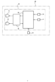
- FIG. 2 is a block diagram of a vehicle lighting system 20 mounted on a motorcycle 1.
- the vehicle lighting system 20 includes a headlamp 10 and a speed sensor 21.
- the vehicle lighting system 20 may also be provided with sensors other than the speed sensor 21 that detect the state of the vehicle.
- the headlamp 10 includes a bank angle sensor 13, an imaging device 14, a light distribution determination unit 15, and an illumination control unit 16.
- the bank angle sensor 13 is a sensor capable of detecting the angle of inclination (so-called bank angle) when the body of the motorcycle 1 inclines (banks) to the left or right with respect to a vertical line.
- the bank angle sensor 13 is composed of, for example, a gyro sensor.
- the imaging device 14 is configured to capture an image of the area in front of the vehicle.
- the imaging device 14 is sensitive to the visible light range, and captures light that is irradiated from the headlamps 10 and reflected by objects in front of the vehicle, or light that is spontaneously emitted from objects in front of the vehicle.
- the imaging device 14 is, for example, a camera.
- the light distribution determination unit 15 is configured to determine the light distribution pattern of the headlamp 10 based on the bank angle of the vehicle body and light points included in an image captured in front of the vehicle. Specifically, the bank angle sensor 13, the imaging device 14, and the speed sensor 21 are connected to the light distribution determination unit 15. The light distribution determination unit 15 determines the light distribution pattern based on the information output from the bank angle sensor 13, the imaging device 14, and the speed sensor 21. The light distribution determination unit 15 determines and updates the light distribution pattern at a predetermined interval. For example, the light distribution determination unit 15 determines and updates the light distribution pattern 60 times per second.
- the light distribution determination unit 15 can be realized by a general-purpose memory and a general-purpose microprocessor that operates in cooperation with the general-purpose memory. Examples of the general-purpose microprocessor include a CPU, an MPU, and a GPU.
- the lighting control unit 16 controls the operation of the headlamp 10 so as to form the light distribution pattern determined by the light distribution determination unit 15. Specifically, the lighting control unit 16 is connected to the light distribution determination unit 15. The lighting control unit 16 is also connected to the low beam lamp unit 11 and the high beam lamp unit 12. The lighting control unit 16 controls the operation of the low beam lamp unit 11 and the high beam lamp unit 12 based on the light distribution pattern output by the light distribution determination unit 15.
- FIG. 3 is a vertical cross-sectional view showing the schematic configuration of the headlamp 10.
- the headlamp 10 includes a lamp body 17 and a transparent cover 18.
- the lamp body 17 has an opening on the front side of the vehicle.
- the transparent cover 18 is attached so as to cover the opening of the lamp body 17.
- the lamp body 17 and the transparent cover 18 form a lamp chamber 19.
- the interior of the lamp chamber 19 contains the low beam lamp unit 11, the high beam lamp unit 12, the bank angle sensor 13, the imaging device 14, the light distribution determination unit 15, and the lighting control unit 16.
- the low beam lamp unit 11 is housed in the lamp chamber 19 of the headlamp 10, just like the high beam lamp unit 12.
- the high beam lamp unit 12 is a so-called projector type lamp, and includes a projection lens 121, a light source unit 122, and a holder 123.
- the holder 123 is attached to the lamp body 17 via a support member (not shown).
- the projection lens 121 is disposed on an optical axis Ax that extends in the fore-and-aft direction of the vehicle.
- the projection lens 121 is a plano-convex aspheric lens with a convex front surface and a flat rear surface.
- the peripheral portion of the projection lens 121 is held on the front end side of the holder 123.
- the projection lens 121 forms a predetermined light distribution pattern by irradiating light from the light source unit 122 forward of the lamp.
- the light source unit 122 is held at the rear end side of the holder 123.
- the light source unit 122 has a light source 1221 and a support plate 1222.
- the light source 1221 is fixed to the front surface of the support plate 1222.
- the light source 1221 is arranged to face forward in the direction of the optical axis Ax.
- the light source 1221 is composed of a semiconductor light source such as a light emitting diode (LED), an EL element, or an LD element.
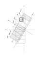
- FIG. 4 is a perspective view showing the schematic structure of the light source unit 122.
- the light source unit 122 has a plurality of light sources 1221.
- the light source unit 122 has light sources 1221a to 1221g arranged in parallel in the left-right direction (direction perpendicular to the optical axis Ax) in seven horizontal columns and one vertical row.
- the light sources 1221a to 1221g are configured as an LED array. Note that the number and arrangement of the light sources 1221 that make up the LED array are not limited to the configuration in this example.
- Each light source 1221 is electrically connected to the lighting control unit 16.
- the light sources 1221 are individually driven and controlled by the lighting control unit 16.
- the lighting control unit 16 has, for example, an LDM (LED Driving Modulator) that controls the drive current supplied to the light sources 1221.
- LDM LED Driving Modulator
- Each light source 1221 is associated with a number of areas that form the illuminable area in front of the vehicle, and light from each light source 1221 is irradiated onto the corresponding individual area.
- the lighting state of each area in the illuminable area can be controlled independently.
- FIGS. 5 and 6 show the light distribution pattern formed by the headlamp 10 mounted on the motorcycle 1.
- H-H represents the horizontal direction
- V-V represents the vertical direction. Note that FIG. 6 shows only the high beam light distribution pattern PH.
- Fig. 5 shows the light distribution pattern formed in front of the vehicle when the motorcycle 1 is traveling straight, that is, when the motorcycle 1 is traveling with the body perpendicular to the road surface.
- a case where the body of the motorcycle 1 is traveling straight includes, for example, a case where the inclination of the body is within ⁇ 10 degrees of the case where the body is vertical.
- the light distribution pattern is formed on a virtual vertical screen placed at a predetermined position in front of the vehicle, for example, 100 m in front of the vehicle.
- the light distribution pattern includes a high beam light distribution pattern PH and a low beam light distribution pattern PL.
- the high beam light distribution pattern PH is a light distribution pattern formed by the high beam lamp unit 12.
- the low beam light distribution pattern PL is a light distribution pattern formed by the low beam lamp unit 11.
- the high beam light distribution pattern PH is a light distribution pattern in which multiple vertically elongated partial patterns PHa to PHg are formed in parallel in the horizontal direction.
- Each partial pattern PHa to PHg is formed by light emitted from light sources 1221a to 1221g.
- Partial pattern PHa is formed by light source 1221a.
- Partial pattern PHb is formed by light source 1221b.
- Partial pattern PHc is formed by light source 1221c.
- Partial pattern PHd is formed by light source 1221d.
- Partial pattern PHe is formed by light source 1221e.
- Partial pattern PHf is formed by light source 1221f.
- Partial pattern PHg is formed by light source 1221g.
- the high beam light distribution pattern PH is formed as a high beam light distribution pattern of different types depending on the situation of the vehicle itself and the vehicle ahead (oncoming vehicles or vehicles ahead) traveling in front of the vehicle, by combining the formation and non-formation of each partial pattern PHa to PHg.
- the light distribution determination unit 15 detects the situation of the vehicle based on the bank angle of the vehicle body detected by the bank angle sensor 13. The light distribution determination unit 15 also detects the situation of the vehicle, including whether the vehicle is moving or stopped, based on the vehicle speed detected by the speed sensor 21. The light distribution determination unit 15 also detects the situation of the vehicle ahead, including the presence or absence and the location of the vehicle ahead, based on light points contained in the image acquired by the imaging device 14. The light distribution determination unit 15 then specifies a light blocking range to prevent light from being irradiated onto the vehicle ahead, based on the situation of the vehicle ahead and the situation of the vehicle ahead. The light distribution determination unit 15 determines the high beam light distribution pattern PH so that the light blocking range is not irradiated.
- the light distribution determination unit 15 defines a light blocking range A ( Figure 5) to prevent light from being irradiated onto the oncoming vehicle 30.
- the light distribution determination unit 15 determines a high beam light distribution pattern PH in which part of the partial pattern is made a non-illuminated area so that light is not irradiated onto the light blocking range A.
- the light distribution determination unit 15 determines a high beam light distribution pattern PH in which partial patterns PHf and PHg corresponding to the area where the oncoming vehicle 30 is present are set as non-illuminated areas.
- the "non-illuminated area” may include an area where light is irradiated at a low illuminance so as not to cause glare to the driver of the oncoming vehicle.
- the light distribution determination unit 15 determines a high beam light distribution pattern PH in which partial patterns PHe and PHf corresponding to the area where the oncoming vehicle 30 is present are set as non-illuminated areas.
- the lighting control unit 16 individually controls the turning on and off of each light source 1221 based on the high beam light distribution pattern PH determined by the light distribution determination unit 15. Specifically, the lighting control unit 16 turns on the light sources 1221 corresponding to the partial pattern that is the illuminated area, and turns off or low illuminance the light sources 1221 corresponding to the partial pattern that is the non-illuminated area. For example, when the dimming method of the light source is analog dimming, the lighting control unit 16 adjusts the DC level of the drive current flowing to the light source 1221. For example, when the dimming method of the light source is PWM (Puse Width Modulation) dimming, the lighting control unit 16 switches the current flowing to the light source 1221 and adjusts the ratio of the on period to adjust the average level of the drive current.
- PWM Puluse Width Modulation
- the lighting control unit 16 turns off the light sources 1221f and 1221g corresponding to the partial patterns PHf and PHg, and turns on the remaining light sources 1221a to 1221e.
- the lighting control unit 16 turns off the light sources 1221e and 1221f corresponding to the partial patterns PHe and PHf, and turns on the remaining light sources 1221a to 1221d and 1221g.
- motorcycle 1 tilts its body as it goes around corners, so the image captured by imaging device 14 is tilted when going around corners compared to when going straight.
- the area to be shaded moves significantly in the image, so it is necessary to continuously identify the area to be shaded from the tilted image, which places a high processing load on the vehicle lighting system.
- the light distribution determination unit 15 detects a forward vehicle based on light points contained in an image as described above, and therefore can perform ADB control suitable for motorcycles with reduced processing load.
- the light distribution determination unit 15 determines a high beam light distribution pattern PH1 with partial patterns PHa to PHg as the illumination area so that the entire illumination area in front of the vehicle is illuminated.
- the lighting control unit 16 drives and controls the light source unit 122 so that light sources 1221a to 1221g are turned on based on the determined high beam light distribution pattern PH1.
- the light distribution determination unit 15 detects a vehicle ahead based on an image of the area ahead of the vehicle on which the high beam light distribution pattern PH1 is formed, captured by the imaging device 14. Specifically, the light distribution determination unit 15 generates a binary image in which the luminance value of each pixel in the image is binarized using a predetermined luminance threshold. The light distribution determination unit 15 then detects predetermined high luminance pixels included in the binary image as light points. In other words, a light point is a collection of one or more high luminance pixels.
- the threshold is appropriately set to a luminance value that allows light from, for example, the headlights of an oncoming vehicle or the rear lights of a leading vehicle to be detected.
- FIG. 7 shows an image captured by the imaging device 14.
- an oncoming vehicle 31 a leading vehicle 32, and a road sign 33 are present in the area ahead of the vehicle.
- the headlights of the oncoming vehicle 31 and the rear lights of the leading vehicle 32 are self-luminous objects and are captured as high-luminance objects.
- the road sign 33 is a light-reflecting object and is captured as a high-luminance object.
- the road sign 33 is an example of a light-reflecting object.
- other light-reflecting objects include delineators, signboards, and objects with retroreflective surfaces in parts visible from the vehicle.
- FIG. 8 is a binary image generated from FIG. 7.
- high-luminance pixel 41 corresponding to the headlamp of oncoming vehicle 31 high-luminance pixel 42 corresponding to the rear lamp of leading vehicle 32, and high-luminance pixel 43 corresponding to road sign 33 are detected as light points.
- the light distribution determination unit 15 defines the area in front of the vehicle that overlaps with the identified high-luminance pixel as a light-blocking range so that light is not irradiated onto the area in front of the vehicle that overlaps with the high-luminance pixel detected as a light spot, and determines the high beam light distribution pattern PH2 so that the light-blocking range is not irradiated.
- a high beam light distribution pattern PH2 is determined in which partial patterns PHa, PHd, PHf, and PHg corresponding to the areas where an oncoming vehicle 31, a leading vehicle 32, and a road sign 33 are present are set as non-illuminated areas.
- the lighting control unit 16 turns on light sources 1221b, 1221c, and 1221e and turns off light sources 1221a, 1221d, 1221f, and 1221g.
- the light distribution determination unit 15 detects a vehicle ahead based on an image of the area in front of the vehicle on which the high beam light distribution pattern PH2 is formed, captured by the imaging device 14.
- FIG. 10 is a binary image generated by binarizing an image captured of the area ahead of the vehicle on which the high beam light distribution pattern PH2 shown in FIG. 9 is formed.
- high-luminance pixel 41 corresponding to the headlamp of oncoming vehicle 31 and high-luminance pixel 42 corresponding to the rear lamp of leading vehicle 32 are detected as light points.
- the light distribution determination unit 15 defines the area in front of the vehicle that overlaps with the high-luminance pixels detected as light points as a light-blocking area, and determines a high-beam light distribution pattern PH3 so that the light-blocking area is not illuminated. Specifically, as shown in FIG. 11, a high-beam light distribution pattern PH3 is determined in which partial patterns PHd, PHf, and PHg corresponding to the area where an oncoming vehicle 31 and a leading vehicle 32 exist are determined as non-illuminated areas.
- the lighting control unit 16 turns on light sources 1221a, 1221b, 1221c, and 1221e and turns off light sources 1221d, 1221f, and 1221g based on the determined high-beam light distribution pattern PH3.
- the headlamp 10 is configured so that the illumination state of a specific area in the illuminable area in front of the vehicle is fixed when the illumination state of the specific area changes a predetermined number of times or more within a predetermined time.
- the light distribution determination unit 15 controls the lighting control unit 16 to fix the state of the light source unit 122 that illuminates the specific area when the state of the light source unit 122 that illuminates the specific area changes a predetermined number of times or more within a predetermined time.
- the lighting control unit 16 is configured to output the state of the light source unit 122 of the high beam lamp unit 12 to the light distribution determination unit 15.
- the lighting control unit 16 controls the operation of the light source unit 122 of the high beam lamp unit 12 each time the light distribution pattern is updated by the light distribution determination unit 15, and also outputs the state of the light source unit 122 to the light distribution determination unit 15.
- the light distribution determination unit 15 controls the lighting control unit 16 to fix the changing state of the light source unit 122 when the state of the light source unit 122 has changed at least two times in succession based on the state of the light source unit 122 output from the lighting control unit 16.
- the lighting control unit 16 controls the on/off state of each light source 1221 of the light source unit 122 each time the light distribution pattern is updated, and outputs the on/off state of each light source 1221 to the light distribution determination unit 15.
- the light distribution determination unit 15 controls the lighting control unit 16 to fix the on/off state of a light source 1221 whose on/off state output from the lighting control unit 16 has changed at least two consecutive times. Here, it is counted that the on/off state has changed once when the light source 1221 changes from a lighting state to an off state, or that the on/off state has changed once when the light source 1221 changes from an off state to a lighting state.
- FIG. 12 shows data on the on/off state of each of the light sources 1221a to 1221g, which is output from the lighting control unit 16 at a predetermined reception interval (frame rate) and acquired by the light distribution determination unit 15.
- ON means that the light source 1221 is in a lighting state.
- OFF means that the light source 1221 is in an off state.
- the light distribution determination unit 15 determines whether the on/off state of the light source 1221 changes from ON to OFF, OFF to ON, and ON to OFF three times in succession over four frames, for example.
- the time it takes for four frames of data to be acquired is an example of a predetermined time during which the state of the light source unit changes. Three times is an example of a predetermined number of times during which the state of the light source unit changes.
- the light distribution determination unit 15 represents the on/off state of each light source 1221 during four frames as a 1-byte variable and stores it in memory as a bit flag, and when the stored bit flag indicates a specific value, it determines that the on/off state of the light source 1221 corresponding to that bit flag is changing continuously.
- the specific value is appropriately set, for example, to the value indicated by the bit flag output when the on/off state of the light source 1221 is changing continuously.
- the determination of whether the light is on or off may be performed every four frames (e.g., between frames 1 and 4, between frames 5 and 8, etc.). Alternatively, the determination of whether the light is on or off may be performed every frame for the four most recent frames (e.g., between frames 1 and 4, between frames 2 and 5, etc.).
- the lighting state of light source 1221a is ON in the first frame, OFF in the second frame, ON in the third frame, and OFF in the fourth frame.
- the lighting states of light sources 1221b and 1221c are ON from the first frame to the fourth frame.
- the lighting states of light sources 1221d, 1221e, and 1221f are OFF from the first frame to the fourth frame.
- the light distribution determination unit 15 determines that the on/off state of the light source 1221a has changed three times in succession, from on to off, from off to on, and from on to off. Then, the light distribution determination unit 15 controls the lighting control unit 16 to fix the on/off state of the light source 1221a.
- the area illuminated by the light emitted by the light source 1221a is an example of a specific area.
- light distribution determination unit 15 when light source 1221a transitions from an off state to an on state, light distribution determination unit 15 outputs control information to lighting control unit 16 so as to temporarily lengthen the transition time (gradual change time) for increasing the luminance of light source 1221a. Based on the control information, lighting control unit 16 adjusts, for example, the increase per unit time of the drive current supplied to light source 1221a, and gradually increases the luminance of light source 1221a. As a result, from the fifth frame onwards, the luminance of light source 1221a is controlled to gradually increase while the on/off state of light source 1221a is fixed at the ON state for multiple frames.
- the light distribution determination unit 15 may be configured to output control information to the lighting control unit 16 so that the on/off state of the light source 1221a is fixed in the same OFF state as in the fourth frame for multiple frames from the fifth frame onwards.
- the light distribution determination unit 15 may be configured to maintain the fixed state for 30 frames from the time when it is determined that the on/off state has changed three times.
- the headlamp 10 even when the light blocking range is defined based on the light points contained in the image, the lighting state of a specific area where the lighting state has changed a predetermined number of times or more within a predetermined time is fixed, so that the phenomenon of light flickering caused by repeated irradiation and non-irradiation of a reflective object can be suppressed.
- the imaging device 14 is included in the headlamp 10. Specifically, the imaging device 14 is arranged in the lamp chamber 19. This makes it possible to omit processing such as calibration between the imaging device 14 and the light distribution determination unit 15. For example, since the motorcycle 1 has a banked body, if the imaging device and the image processing unit are arranged apart, complex image processing such as rotating the captured image during image processing is required. Also, if the imaging device and the image processing unit are arranged apart, parallax correction may be required or the position of the light blocking range of the lamp's irradiation light may shift relative to the captured image. However, in this embodiment, the imaging device 14 is arranged in the same lamp chamber 19 as the light distribution determination unit 15.
- the imaging device 14 and the light distribution determination unit 15 are arranged together in a banked configuration, making it possible to omit complex image processing. Also, since the imaging device 14 is arranged near the light distribution determination unit 15, parallax correction is not required and the shift in the light blocking range position relative to the captured image can be suppressed.
- light flicker is detected when the on/off state of the light source 1221 changes three consecutive times over four frames.
- light flicker may also be detected, for example, when the on/off state of the light source 1221 changes two consecutive times over three frames.
- light flicker may be detected, for example, when the on/off state of the light source 1221 changes continuously over five or more frames.
- the bank angle sensor 13 is included in the headlamp 10.
- the bank angle sensor 13 may be configured separately from the headlamp 10. That is, the vehicle lighting system 20 may be configured to have the headlamp 10, the bank angle sensor 13, and the speed sensor 21.
- the bank angle sensor 13 and the speed sensor 21 are connected to the headlamp 10 via a vehicle control unit 22.
- the vehicle control unit 22 is configured to be able to communicate with the light distribution determination unit 15, for example, by CAN (Controller Area Network) communication or LIN (Local Interconnect Network) communication.
- the imaging device 14 is included in the headlamp 10.
- the imaging device 14 may be configured separately from the headlamp 10 together with the bank angle sensor 13. That is, the vehicle lighting system 20 may be configured to have the headlamp 10, the bank angle sensor 13, the imaging device 14, and the speed sensor 21.
- the bank angle sensor 13, the imaging device 14, and the speed sensor 21 are connected to the headlamp 10 via a vehicle control unit 22.
- the vehicle control unit 22 is configured to be able to communicate with the light distribution determination unit 15, for example, by CAN communication or LIN communication.
- the imaging device 14 and the light distribution determination unit 15 can be configured to be banked together, and complicated image processing can be omitted. Furthermore, if the imaging device 14 is disposed near the headlamp 10, the imaging device 14 can be disposed close to the light distribution determination unit 15, making parallax correction unnecessary and suppressing deviation of the light blocking range position with respect to the captured image.
- the light distribution determination unit 15 and the lighting control unit 16 are configured as separate entities. However, for example, as shown in Fig. 13 and Fig. 14, the light distribution determination unit 15 and the lighting control unit 16 may be integrated and configured as one device 50.
- the light distribution determination unit 15 and the lighting control unit 16 are mounted on the same board.
- wiring and communication between the boards are not required, the occurrence of communication delays can be suppressed, and the mounting space can be narrowed.
- the light source unit 122 has an LED array composed of a plurality of light sources 1221a to 1221g, and the lighting control unit 16 is configured to drive and control the light sources 1221a to 1221g individually.
- the light source unit 122 may be composed of a scanning optical type pattern forming device that scans light from a light source such as a blade scan type device, a matrix type pattern forming device such as a DMD (Digital Mirror Device) or a liquid crystal device, etc.
- the light distribution determination unit 15 is configured to control the lighting control unit 16 to fix the lighting state of the light source of the blade scan type device, the orientation of the reflector of the DMD, the state of the liquid crystal element of the liquid crystal device, etc., as the state of the light source unit. More specifically, the light distribution determination unit 15 controls the lighting control unit 16 to fix the on/off and lighting intensity during a certain time period within one scanning period of the light source of the blade scan type device, the orientation and reflection angle of each reflector of the DMD, the state of each liquid crystal element of the liquid crystal device, etc.
- the light distribution determination unit 15 fixes the state of the light source unit 122 of the high beam lamp unit 12 when the state of the light source unit 122 changes a predetermined number of times or more within a predetermined time.
- the light distribution determination unit 15 may be configured to fix the state of the light source unit when the state of the cornering lamp light source unit changes a predetermined number of times or more within a predetermined time.
- motorcycle 1 is given as an example of a vehicle that travels around corners by leaning the body in the direction of the turn.
- the number of wheels on the vehicle is not limited.
- vehicles that travel around corners by leaning the body in the direction of the turn can also include three-wheeled motor vehicles.
Landscapes
- Engineering & Computer Science (AREA)
- Mechanical Engineering (AREA)
- Lighting Device Outwards From Vehicle And Optical Signal (AREA)
Abstract
Description
曲がる方向に向かって車体を傾けることでコーナを走行する車両に搭載される車両用灯具であって、
前記車体のバンク角および前記車両の周囲を撮像した画像に含まれる光点に基づいて、配光パターンを決定する配光決定部と、
照明可能領域が複数の領域に分割され、個々の領域の照明状態をそれぞれ独立して制御可能な光源ユニットと、
前記配光パターンを形成するように前記光源ユニットを制御する点灯制御部と、を備えており、
特定の前記領域の前記照明状態が所定時間内に所定回数以上変化している時に、特定の前記領域の前記照明状態が固定される。
上記の実施形態において、配光決定部15と点灯制御部16は、別体として構成されている。しかしながら、例えば図13や図14に示すように、配光決定部15と点灯制御部16は、一体化されて一つのデバイス50として構成されてもよい。具体的には、デバイス50において、配光決定部15および点灯制御部16は、同一基板に実装される。この場合、配光決定部15と点灯制御部16がそれぞれ別の基板に実装されている構成と比べて、基板間の配線および通信が不要となり、通信遅延の発生を抑制でき、また、搭載スペースを狭くできる。
Claims (9)
- 曲がる方向に向かって車体を傾けることでコーナを走行する車両に搭載される車両用灯具であって、
前記車体のバンク角および前記車両の周囲を撮像した画像に含まれる光点に基づいて、配光パターンを決定する配光決定部と、
照明可能領域が複数の領域に分割され、個々の領域の照明状態をそれぞれ独立して制御可能な光源ユニットと、
前記配光パターンを形成するように前記光源ユニットを制御する点灯制御部と、を備えており、
特定の前記領域の前記照明状態が所定時間内に所定回数以上変化している時に、特定の前記領域の前記照明状態が固定される、車両用灯具。 - 前記配光決定部は、特定の前記領域を照らす前記光源ユニットの状態が所定時間内に所定回数以上変化している時に、特定の前記領域を照らす前記光源ユニットの状態を固定させるように前記点灯制御部を制御する、請求項1に記載の車両用灯具。
- 前記点灯制御部は、前記光源ユニットの状態を前記配光決定部に出力する、請求項1または請求項2に記載の車両用灯具。
- 前記配光決定部は、前記点灯制御部から出力された前記光源ユニットの状態が少なくとも連続して2回以上変化している時に、当該変化している前記光源ユニットの状態を固定させるように前記点灯制御部を制御する、請求項3に記載の車両用灯具。
- 前記光源ユニットは、個々の前記領域を照らす複数の半導体光源を有し、
前記点灯制御部は、前記複数の半導体光源を個別に駆動制御するように構成されている、請求項1または請求項2に記載の車両用灯具。 - 前記点灯制御部は、個々の前記半導体光源の点消灯状態を前記配光決定部に出力しており、
前記配光決定部は、前記点灯制御部から出力された点消灯状態が少なくとも連続して2回以上変化している前記半導体光源の点消灯状態を固定させるように前記点灯制御部を制御する、請求項5に記載の車両用灯具。 - 前記配光決定部と前記点灯制御部は、同一基板に実装されている、請求項1または請求項2に記載の車両用灯具。
- 前記車両の周囲を撮像する撮像装置を備える、請求項1または請求項2に記載の車両用灯具。
- 前記車両の周囲を撮像する撮像装置と、
請求項1または請求項2に記載の車両用灯具と、
を備える、車両用灯具システム。
Priority Applications (3)
| Application Number | Priority Date | Filing Date | Title |
|---|---|---|---|
| EP23903216.2A EP4635797A4 (en) | 2022-12-16 | 2023-11-20 | VEHICLE HEADLIGHT AND VEHICLE HEADLIGHT SYSTEM |
| CN202380086326.8A CN120379862A (zh) | 2022-12-16 | 2023-11-20 | 车辆用灯具以及车辆用灯具系统 |
| JP2024564236A JPWO2024127919A1 (ja) | 2022-12-16 | 2023-11-20 |
Applications Claiming Priority (2)
| Application Number | Priority Date | Filing Date | Title |
|---|---|---|---|
| JP2022201510 | 2022-12-16 | ||
| JP2022-201510 | 2022-12-16 |
Publications (1)
| Publication Number | Publication Date |
|---|---|
| WO2024127919A1 true WO2024127919A1 (ja) | 2024-06-20 |
Family
ID=91485632
Family Applications (1)
| Application Number | Title | Priority Date | Filing Date |
|---|---|---|---|
| PCT/JP2023/041626 Ceased WO2024127919A1 (ja) | 2022-12-16 | 2023-11-20 | 車両用灯具および車両用灯具システム |
Country Status (4)
| Country | Link |
|---|---|
| EP (1) | EP4635797A4 (ja) |
| JP (1) | JPWO2024127919A1 (ja) |
| CN (1) | CN120379862A (ja) |
| WO (1) | WO2024127919A1 (ja) |
Citations (5)
| Publication number | Priority date | Publication date | Assignee | Title |
|---|---|---|---|---|
| JP2015064964A (ja) | 2013-09-24 | 2015-04-09 | 株式会社小糸製作所 | 車両用前照灯 |
| JP2019172105A (ja) * | 2018-03-28 | 2019-10-10 | ダイハツ工業株式会社 | 配光制御装置 |
| JP2020104561A (ja) * | 2018-12-26 | 2020-07-09 | 株式会社小糸製作所 | 車両用灯具システム、車両用灯具の制御装置および車両用灯具の制御方法 |
| JP2020117155A (ja) * | 2019-01-25 | 2020-08-06 | 株式会社小糸製作所 | 車両用灯具システム、車両用灯具の制御装置および車両用灯具の制御方法 |
| JP2022047882A (ja) * | 2020-09-14 | 2022-03-25 | 株式会社小糸製作所 | 車両用灯具および車両システム |
Family Cites Families (4)
| Publication number | Priority date | Publication date | Assignee | Title |
|---|---|---|---|---|
| FR2911206B1 (fr) * | 2006-12-21 | 2009-05-08 | Valeo Vision Sa | Procede de discrimination automatique de zones lumineuses detectees par un dispositif d'aide a la conduite pour vehicule. |
| CN103249597B (zh) * | 2010-08-06 | 2015-04-29 | 丰田自动车株式会社 | 车辆配光控制装置以及方法 |
| DE102012210467A1 (de) * | 2012-06-21 | 2013-12-24 | Bayerische Motoren Werke Aktiengesellschaft | Verfahren zur automatischen Anpassung einer Fahrzeugbeleuchtung an eine Umgebung des Fahrzeugs |
| US11007926B1 (en) * | 2020-03-16 | 2021-05-18 | Arm Limited | Smart headlights |
-
2023
- 2023-11-20 CN CN202380086326.8A patent/CN120379862A/zh active Pending
- 2023-11-20 EP EP23903216.2A patent/EP4635797A4/en active Pending
- 2023-11-20 WO PCT/JP2023/041626 patent/WO2024127919A1/ja not_active Ceased
- 2023-11-20 JP JP2024564236A patent/JPWO2024127919A1/ja active Pending
Patent Citations (5)
| Publication number | Priority date | Publication date | Assignee | Title |
|---|---|---|---|---|
| JP2015064964A (ja) | 2013-09-24 | 2015-04-09 | 株式会社小糸製作所 | 車両用前照灯 |
| JP2019172105A (ja) * | 2018-03-28 | 2019-10-10 | ダイハツ工業株式会社 | 配光制御装置 |
| JP2020104561A (ja) * | 2018-12-26 | 2020-07-09 | 株式会社小糸製作所 | 車両用灯具システム、車両用灯具の制御装置および車両用灯具の制御方法 |
| JP2020117155A (ja) * | 2019-01-25 | 2020-08-06 | 株式会社小糸製作所 | 車両用灯具システム、車両用灯具の制御装置および車両用灯具の制御方法 |
| JP2022047882A (ja) * | 2020-09-14 | 2022-03-25 | 株式会社小糸製作所 | 車両用灯具および車両システム |
Non-Patent Citations (1)
| Title |
|---|
| See also references of EP4635797A1 |
Also Published As
| Publication number | Publication date |
|---|---|
| CN120379862A (zh) | 2025-07-25 |
| EP4635797A4 (en) | 2026-04-08 |
| JPWO2024127919A1 (ja) | 2024-06-20 |
| EP4635797A1 (en) | 2025-10-22 |
Similar Documents
| Publication | Publication Date | Title |
|---|---|---|
| US11805587B2 (en) | Vehicle illumination system, vehicle system, lamp unit and vehicle lamp | |
| US10919438B2 (en) | Vehicle lamp system, vehicle lamp control device and vehicle lamp control method | |
| CN115362086B (zh) | 车辆用前照灯 | |
| CN110770081B (zh) | 车辆用灯具系统、车辆用灯具的控制装置及车辆用灯具的控制方法 | |
| CN113382888B (zh) | 机动车辆的照明系统 | |
| JP7260341B2 (ja) | 車両用灯具の制御装置、車両用灯具の制御方法、車両用灯具システム | |
| EP3733452A1 (en) | Vehicle lamp system, vehicle lamp control device, and vehicle lamp control method | |
| JP7688765B2 (ja) | 車両用灯具および車両システム | |
| JP2011110999A (ja) | 車両用前照灯システム | |
| JP7407096B2 (ja) | 車両用ランプの制御方法及び制御装置 | |
| JP7746312B2 (ja) | 車両用前照灯 | |
| JP2020131922A (ja) | 車両用灯具 | |
| EP2100771B1 (en) | Vehicle headlight apparatus and method for controlling same | |
| JP7084392B2 (ja) | 車両用灯具システム、車両用灯具の制御装置及び車両用灯具の制御方法 | |
| CN115190848A (zh) | 车辆用前照灯 | |
| JP7804638B2 (ja) | 車両用灯具 | |
| EP4635797A1 (en) | Vehicle lamp and vehicle lamp system | |
| EP4497633B1 (en) | Vehicular lamp system, light distribution control device, and light distribution control method | |
| CN118804853A (zh) | 灯系统、灯控制方法、灯控制程序以及车辆 | |
| WO2022196296A1 (ja) | 車両用灯具の制御装置、車両用灯具の制御方法、車両用灯具システム | |
| JP7598377B2 (ja) | 車両システムおよび車両用灯具 | |
| JP7544702B2 (ja) | 車両用灯具システム、車両用灯具の制御装置および車両用灯具の制御方法 | |
| WO2024203680A1 (ja) | 配光可変ランプの制御装置、車両用灯具、ソフトウェアプログラム | |
| WO2024142991A1 (ja) | 車両用灯具、配光可変ランプのコントローラおよびその制御方法、ソフトウェアプログラム | |
| WO2025013641A1 (ja) | 前照灯の制御装置、前照灯の制御方法、前照灯システム |
Legal Events
| Date | Code | Title | Description |
|---|---|---|---|
| 121 | Ep: the epo has been informed by wipo that ep was designated in this application |
Ref document number: 23903216 Country of ref document: EP Kind code of ref document: A1 |
|
| WWE | Wipo information: entry into national phase |
Ref document number: 2024564236 Country of ref document: JP |
|
| WWE | Wipo information: entry into national phase |
Ref document number: 202380086326.8 Country of ref document: CN |
|
| WWE | Wipo information: entry into national phase |
Ref document number: 2023903216 Country of ref document: EP |
|
| NENP | Non-entry into the national phase |
Ref country code: DE |
|
| ENP | Entry into the national phase |
Ref document number: 2023903216 Country of ref document: EP Effective date: 20250716 |
|
| WWP | Wipo information: published in national office |
Ref document number: 202380086326.8 Country of ref document: CN |
|
| WWP | Wipo information: published in national office |
Ref document number: 2023903216 Country of ref document: EP |