WO2024128223A1 - ジョー組立体及びこれを用いた外科用器具 - Google Patents
ジョー組立体及びこれを用いた外科用器具 Download PDFInfo
- Publication number
- WO2024128223A1 WO2024128223A1 PCT/JP2023/044430 JP2023044430W WO2024128223A1 WO 2024128223 A1 WO2024128223 A1 WO 2024128223A1 JP 2023044430 W JP2023044430 W JP 2023044430W WO 2024128223 A1 WO2024128223 A1 WO 2024128223A1
- Authority
- WO
- WIPO (PCT)
- Prior art keywords
- jaws
- pair
- jaw assembly
- support portion
- movable member
- Prior art date
- Legal status (The legal status is an assumption and is not a legal conclusion. Google has not performed a legal analysis and makes no representation as to the accuracy of the status listed.)
- Ceased
Links
Images





Classifications
-
- A—HUMAN NECESSITIES
- A61—MEDICAL OR VETERINARY SCIENCE; HYGIENE
- A61B—DIAGNOSIS; SURGERY; IDENTIFICATION
- A61B17/00—Surgical instruments, devices or methods
- A61B17/28—Surgical forceps
- A61B17/29—Forceps for use in minimally invasive surgery
-
- A—HUMAN NECESSITIES
- A61—MEDICAL OR VETERINARY SCIENCE; HYGIENE
- A61B—DIAGNOSIS; SURGERY; IDENTIFICATION
- A61B17/00—Surgical instruments, devices or methods
- A61B17/28—Surgical forceps
- A61B17/29—Forceps for use in minimally invasive surgery
- A61B2017/2926—Details of heads or jaws
- A61B2017/2932—Transmission of forces to jaw members
- A61B2017/2933—Transmission of forces to jaw members camming or guiding means
- A61B2017/2934—Transmission of forces to jaw members camming or guiding means arcuate shaped guiding means
-
- A—HUMAN NECESSITIES
- A61—MEDICAL OR VETERINARY SCIENCE; HYGIENE
- A61B—DIAGNOSIS; SURGERY; IDENTIFICATION
- A61B17/00—Surgical instruments, devices or methods
- A61B17/28—Surgical forceps
- A61B17/29—Forceps for use in minimally invasive surgery
- A61B2017/2926—Details of heads or jaws
- A61B2017/2932—Transmission of forces to jaw members
- A61B2017/2933—Transmission of forces to jaw members camming or guiding means
- A61B2017/2936—Pins in guiding slots
-
- A—HUMAN NECESSITIES
- A61—MEDICAL OR VETERINARY SCIENCE; HYGIENE
- A61B—DIAGNOSIS; SURGERY; IDENTIFICATION
- A61B17/00—Surgical instruments, devices or methods
- A61B17/28—Surgical forceps
- A61B17/29—Forceps for use in minimally invasive surgery
- A61B2017/2926—Details of heads or jaws
- A61B2017/2932—Transmission of forces to jaw members
- A61B2017/2939—Details of linkages or pivot points
-
- A—HUMAN NECESSITIES
- A61—MEDICAL OR VETERINARY SCIENCE; HYGIENE
- A61B—DIAGNOSIS; SURGERY; IDENTIFICATION
- A61B17/00—Surgical instruments, devices or methods
- A61B17/28—Surgical forceps
- A61B17/29—Forceps for use in minimally invasive surgery
- A61B2017/2926—Details of heads or jaws
- A61B2017/2932—Transmission of forces to jaw members
- A61B2017/2939—Details of linkages or pivot points
- A61B2017/294—Connection of actuating rod to jaw, e.g. releasable
Definitions
- the present invention relates to a jaw assembly for use in a robot, manipulator, etc., and a surgical instrument using the same.
- a conventional jaw assembly such as that disclosed in Patent Document 1, has a pair of jaws that can be opened and closed relative to each other and are rotatably supported on a sleeve by a pin.
- a reciprocating actuating wire is connected to each of the pair of jaws, and the reciprocating actuating wire rotates the pair of jaws around a pin, allowing them to be opened and closed.
- the joint between the jaw, which acts as the force point, and the actuating wire can be positioned away from the pin, which acts as the fulcrum and the center of rotation, making it possible to increase the force acting between the jaws in response to the operation of the actuating wire.
- the present invention provides a jaw assembly comprising a pair of jaws that can be opened and closed relative to each other, a support part that rotatably supports at least one of the pair of jaws to enable the opening and closing, and a movable member that is rotatably connected to at least one of the pair of jaws rotatably supported on the support part and can move back and forth relative to the support part, the support part having a recess that opens at an edge in a direction intersecting the direction of the reciprocating movement of the movable member, and at least one of the pair of jaws rotatably supported on the support part having a rotating shaft part that rotatably engages with the recess from the outside in the intersecting direction around an axis.
- the present invention also provides a surgical instrument using the jaw assembly.
- the present invention improves the force acting between the jaws.
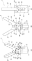
- FIG. 1 is a front view showing a pair of forceps as a surgical instrument using a jaw assembly according to a first embodiment of the present invention.
- 2 is a perspective view of the jaw assembly of the forceps of FIG. 1 in a closed position;
- FIG. FIG. 3 is a perspective view of the jaw assembly of FIG. 2 in an open position.
- 4 is an exploded perspective view of the jaw assembly of FIG. 2;
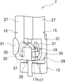
- FIG. 5 is a front view showing the relationship between the rotation center of the jaws and the protrusions of the jaw assembly of FIG. 2.
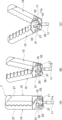
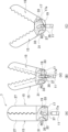
- FIG. 6A-6C are perspective views illustrating opening and closing of the jaw assembly of FIG. 7A-7C are front views showing the opening and closing of the jaw assembly of FIG. FIG.
- FIG. 8 is a perspective view showing a portion of a jaw assembly according to a second embodiment of the present invention.
- 9A and 9B are perspective views showing the jaws of the jaw assembly of FIG. 8 from the front and back sides, respectively.
- 10(A) to (C) show a closed state of a jaw assembly according to a third embodiment of the present invention, where FIG. 10(A) is a perspective view, FIG. 10(B) is a front view, and FIG. 10(C) is a side view.
- 11(A) to (C) show the jaw assembly of FIGS. 10(A) to (C) in an open state, with FIG. 11(A) being a perspective view, FIG. 11(B) being a front view, and FIG. 11(C) being a side view.
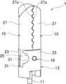
- the jaw assembly 7 includes a pair of jaws 15, a support portion 13, and a movable member 17.
- the pair of jaws 15 can be opened and closed relative to each other.
- the support part 13 rotatably supports at least one of the pair of jaws 15, allowing the pair of jaws 15 to be opened and closed.
- the movable member 17 is connected to at least one of the pair of jaws 15 rotatably supported by the support part 13 so as to be rotatable relative to the jaws 15, and is a member that can move back and forth relative to the support part 13.
- both jaws 15 are rotatably connected to the support part 13.
- the support portion 13 has a recess 25 that opens at an edge in a direction intersecting the direction of reciprocating movement of the movable member 17, and at least one of a pair of jaws 15 rotatably supported on the support portion 13 has a rotating shaft portion 31 that engages with the recess 25 from the outside in the intersecting direction of the recess 25 so as to be rotatable around the axis.
- the jaw assembly 7 can be configured as a cam type, a link type, or the like.
- the cam type it is provided with a cam portion 19.
- the cam portion 19 is provided between the support portion 13 and at least one of the pair of jaws 15 rotatably supported by the support portion 13, and rotates at least one of the pair of jaws 15 rotatably supported by the support portion 13 in response to the reciprocating movement of the movable member 17, thereby opening and closing the pair of jaws 15.
- the cam portion 19 may maintain the engagement of the rotating shaft portion 31 with the recess 25.
- At least one of the jaws 15 rotatably supported by the support portion 13 may have a rotation center RC and a connection portion to the movable member 17 positioned apart in a direction intersecting the direction of reciprocating movement of the movable member 17 when at least one pair of jaws 15 is in a closed state.
- the rotation center RC and the connection portion of each jaw 15 may be positioned on opposite sides of the intersecting direction across the opening/closing center OC of the pair of jaws 15.
- the movable member 17 may have a pair of openings 17a and one of the protrusions 33 that is the connecting portion, and the pair of jaws 15 may each have the other of the openings 17a and protrusions 33 that engage with one of the pair of openings 17a and protrusions 33.
- the opening 17a is a long hole that allows relative movement of the protrusion 33 in the cross direction, and may allow the rotating shaft portion 31 to engage with and disengage from the recess 25 before the rotating shaft portion 31 retains its engagement with the recess 25.
- the jaw assembly 7 can be applied to various robots and manipulators, but can also be used in surgical instruments, for example.
- FIG. 1 is a front view showing a pair of forceps as a surgical instrument using a jaw assembly according to a first embodiment of the present invention.
- the forceps 1 of this embodiment is a surgical instrument used in surgical support robots, surgical support manipulators, etc., and includes a shaft 3, a bending portion 5, and a jaw assembly 7.
- forceps 1 are shown as an example of a surgical instrument, but as long as it opens and closes the jaw 15 described below, it can be a surgical instrument with various functions such as grasping, peeling, cutting, etc.
- the jaw assembly 7 can be applied to devices such as robots and manipulators that have various functions such as grasping, peeling, cutting, etc.
- the shaft 3 is formed in a cylindrical shape and is connected to a surgical support robot or a surgical support manipulator, for example, so as to be rotatable around an axis.
- a bending portion 5 is provided at the tip of the shaft 3.
- the shape of the shaft 3 is not particularly limited.
- the bending portion 5 has a joint function and is a portion that allows the forceps 1 to bend and extend.
- the bending portion 5 is made by stacking multiple wave washers 5a in the axial direction and maintaining the stacked state by welding or the like.
- the bending portion 5 is not particularly limited as long as it is capable of bending and extending, and it can also be a coil spring, bellows, or the like.
- the axial direction refers to the direction along the axis of the forceps 1.
- the bending portion 5 has wires 9 inserted axially at predetermined circumferential intervals, and is bent and extended by manipulating the wires 9.
- the circumferential direction refers to the direction along the outer periphery of the forceps 1.
- a core material not shown
- an operating member 11 that opens and closes the jaw 15, which will be described later.
- the jaw assembly 7 is supported at the tip of the bending portion 5.
- Figure 2 is a perspective view showing the jaw assembly of the forceps in Figure 1 in a closed state
- Figure 3 is a perspective view showing the same in an open state
- Figure 4 is an exploded perspective view of the jaw assembly in Figure 2.
- Figure 5 is a front view showing the relationship between the jaw rotation center and the protrusion of the jaw assembly in Figure 2.
- Figures 6 (A) to (C) are perspective views showing the jaw assembly in Figure 2 when opened and closed
- Figures 7 (A) to (C) are front views of the same. Note that support portion 13 is omitted in Figures 6 (A) to 7 (C).
- the jaw assembly 7 includes a support portion 13, a pair of jaws 15, a movable member 17, and a cam portion 19.
- the support portion 13 is connected to the bending portion 5, and as shown in Figs. 2 to 4, supports the pair of jaws 15 rotatably so that they can be opened and closed.
- the pair of jaws 15 are both supported by the support portion 13 so that they can be opened from both sides.
- the support portion 13 is formed in a cylindrical shape as a whole, but is not particularly limited to this.
- a slit 21 is provided on the tip side in the axial direction of this support portion 13, and support wall portions 23 that support the jaws 15 are defined on one and the other sides of the radial direction (hereinafter, the first radial direction) sandwiching the slit 21.
- This support portion 13 has recesses 25 that open on both sides in the radial direction (hereinafter, the second radial direction) along the slit 21.
- the second radial direction is perpendicular to the first radial direction in a plan view.
- the radial direction refers to the direction along the diameter of the forceps 1, and is a direction that intersects with the reciprocating movement direction of the movable member 17.
- the recesses 25 are provided in the support wall 23 and are formed in an inverted fan shape, particularly a semicircle, when viewed from the front in the first radial direction.
- the chord of the fan shape (diameter of the semicircle) of each of the recesses 25 is located at the side edge of the support wall 23 in the second radial direction and opens outward.
- the inner surface of the recess 25 gradually becomes larger in one radial direction from the side edge of the support wall portion 23 toward the inside in the second radial direction in accordance with the outer peripheral shape of the support portion 13.
- the shape of the recess 25 is arbitrary, and it is sufficient if it can support the rotating shaft portion 31 described later so as to be able to rotate freely around the axis.
- the pair of jaws 15 open and close relative to each other as shown in Figures 2 to 7 (C), and in this embodiment are configured as grippers that grip by closing. These jaws 15 are formed in the same shape and are arranged with the front and back reversed in the first radial direction. However, the jaws 15 do not need to be the same shape and may have different shapes. Each jaw 15 has a main body portion 27, an arm 29, and a rotating shaft portion 31.
- the main body 27 is rod-shaped and performs the opening and closing operation.
- the main body 27 has a wave-shaped interlocking portion 27a that interlocks with the main body 27 in a closed state in the second radial direction.
- a rotating shaft portion 31 is provided at the base end of the main body 27 in the axial direction via an arm 29.
- the arm 29 is formed in a plate shape and has a smaller thickness in the first radial direction than the main body 27.
- the arm 29 protrudes in the axial direction from the base end of the main body 27 and protrudes from the meshing portion 27a in the second radial direction, which is the intersecting direction.
- the arm 29 is inserted into the slit 21 of the support portion 13.
- a rotating shaft portion 31 is provided on one side of the arm 29 in the second radial direction, and a protrusion 33 is provided on the other side.
- a cam groove 37 of the cam portion 19, which will be described later, is provided between the rotating shaft portion 31 and the protrusion 33.
- the rotating shaft portion 31 is formed in a sector shape, particularly a semicircular shape, when viewed from the front in the first radial direction.
- This semicircular rotating shaft portion 31 engages with the recess 25 of the semicircular support portion 13 from the outside in the second radial direction.
- the rotating shaft portion 31 is supported in the recess 25 so as to be rotatable about its axis by sliding.
- the configuration of the rotating shaft portion 31 may be rod-shaped or other shapes, so long as it is supported in the recess 25 so as to be rotatable about its axis by sliding.
- the engagement state of the rotating shaft portion 31 of the jaw 15 with the recess 25 of the support portion 13 is maintained by the cam portion 19, as described below.
- the dimension of the rotating shaft 31 in the first radial direction gradually increases from both side edges of the support wall 23 toward the inside in the second radial direction.
- the semicircular shapes of the rotating shaft 31 and the recess 25 have the same radius of curvature and depth in the second radial direction. Therefore, the center of rotation RC is located at the side edge of the support 13 in the second radial direction.
- the rotation center RC can be positioned outside the support portion 13 in the second radial direction.
- the recess 25 can be made shallower by making the central angle of the recess 25 smaller than the central angle of the rotating shaft portion 31.
- the rotation center RC can be positioned outside the support portion 13 in the second radial direction.
- the recess 25 can be deepened by making the central angle of the recess 25 larger than the central angle of the rotating shaft portion 31.
- the position of the rotation center RC can be easily set by setting the recess 25 and the rotation shaft portion 31.
- the protrusion 33 is a connecting part for the movable member 17 described later.
- the protrusion 33 is provided to protrude from the surface of the arm 29 opposite the rotating shaft portion 31 in the first radial direction.
- the shape of the protrusion 33 is cylindrical, but is not particularly limited.
- this protrusion 33 When the pair of jaws 15 are in a closed state, this protrusion 33 is positioned away from the rotation center RC in the second radial direction. In this embodiment, it is positioned on the opposite side of the opening/closing center OC (FIG. 7B) of the body portion 27 of the jaws 15 from the rotation center RC.
- the opening/closing center OC is the center position when setting the opening/closing angle of the body portion 27 of the jaws 15, and in this embodiment, it is located in the center of the support portion 13 in the second radial direction.
- the jaw 15 is opened and closed by the movable member 17 via this protrusion 33.
- the movable member 17 is connected to both of the pair of jaws 15 so as to be rotatable relative to each other, and is capable of reciprocating relative to the support portion 13.
- the movable member 17 is formed in a plate shape, and is disposed between the arms 29 of the jaws 15 in the first radial direction.
- the movable member 17 is provided with a pair of openings 17a penetrating in the first radial direction. These openings 17a are arranged side by side in the second radial direction, and the protrusions 33 of the jaw 15 are inserted into each of them in the first radial direction. Note that the protrusions 33 may be provided on the movable member 17, and the openings 17a may be provided on the jaw 15. Therefore, it is sufficient to provide one of the protrusions 33 and the openings 17a on the movable member 17, and the other on the jaw 15.
- the opening 17a is an elongated hole that is long in the second radial direction. This allows the protrusion 33 to move relative to the recess 25, and allows the rotating shaft 31 to engage with and disengage from the recess 25 before the rotating shaft 31 retains its engagement with the recess 25. Therefore, when engaging the rotating shaft 31 with the recess 25, the protrusion 33 is inserted in advance within the opening 17a, and the protrusion 33 is moved in the second radial direction within the opening 17a, making the operation easy.
- the movable member 17 is integrally provided with a cylindrical connection portion 17b that is connected to the operating member 11.
- the movable member 17 is connected to the operating member 11 by this connection portion 17b, and can be moved back and forth by the operating member 11.
- the movable member 17 exerts a force around the center of rotation RC on the jaws 15 via the protrusion 33, which is the connecting part.
- the center of rotation RC is shaped so that the rotation shaft portion 31 of the jaws 15 engages with the recess 25 of the support portion 13 from the outside in the second radial direction, the distance L between the protrusion 33 and the center of rotation RC can be lengthened to improve the rotational force of the jaws 15. As a result, it is possible to increase the force acting between the pair of jaws 15 in response to operation.
- the center of rotation RC is positioned on the side edge of the support portion 13 in the second radial direction, making it possible to position the center of rotation RC as far outward as possible while preventing the forceps 1 and jaw assembly 7 from becoming too large in the second radial direction.
- the cam portions 19 are provided between the support portion 13 and the pair of jaws 15, and rotate the pair of jaws 15 to open and close in response to the reciprocating movement of the movable member 17.
- the cam portion 19 can take various forms, but in this embodiment it consists of a cam pin 35 attached to the support portion 13 and a cam groove 37 provided in each jaw 15.
- the cam pin 35 is attached to the through hole 39 of the support part 13, and the tip thereof protrudes in the first radial direction into the slit 21 of the support part 13. In the slit 21, the tip of the cam pin 35 engages with the cam groove 37.
- the cam pin 35 has a cylindrical shape, but is not particularly limited to this shape.
- a cam groove 37 is provided in the arm 29 of each jaw 15.
- the cam groove 37 is formed in an arc shape around the center of rotation RC.
- the cam groove 37 is a recessed portion, but it may also be a through hole.
- the cam pin 35 moves relatively along this cam groove 37, causing the jaw 15 to open and close.
- cam groove 37 and cam pin 35 of the cam portion 19 regulate the movement of the jaw 15, making it possible to maintain the engagement of the rotating shaft portion 31 with the recessed portion 25.
- the jaws 15 can be opened and closed by reciprocating the movable member 17 in the axial direction via the operating member 11.
- the pair of jaws 15 receive a force around the rotation center RC in the opening direction because the rotation center RC and the protrusion 33 are positioned apart in the second radial direction. Furthermore, the pair of jaws 15 receive a force around the rotation center RC in the opening direction more reliably due to the action of the cam portion 19. As a result, the pair of jaws 15 rotate about the rotation center RC, and the main body portions 27 open apart.
- the rotation shaft portion 31 of the jaw 15 is shaped to engage with the recess 25 of the support portion 13 from the outside in the second radial direction, so the distance between the protrusion 33 and the rotation center RC can be increased to improve the rotation force of the jaw 15. As a result, it is possible to improve the opening force acting between the pair of jaws 15 in response to the operating force of the movable member 17.
- the forceps 1 allows the jaws 15 to grasp reliably with little operating force.
- FIG. 8 is a perspective view showing a part of a jaw assembly according to a second embodiment of the present invention.
- FIGS. 9(A) and (B) are perspective views showing the jaws of the jaw assembly in FIG. 8 from the front side and the back side, respectively. Note that in the second embodiment, the same reference numerals are used for configurations corresponding to those in the first embodiment, and duplicated explanations are omitted.
- the cam pin 35 of the cam portion 19 is omitted, and the protrusion 33 serves as the cam pin 35.
- the arm 29 of the jaw 15 is provided with a rotating shaft portion 31 on one side in the second radial direction, and a protrusion 33 is provided on the other side on the opposite side in the first radial direction from the surface on which the rotating shaft portion 31 is provided.
- the arm 29 is provided with a cam groove 37 of the cam portion 19 on one side in the second radial direction on the same surface as the protrusion 33.
- the cam groove 37 is formed in an arc shape around the rotation center RC of the opposing jaw 15.
- the tip of the protrusion 33 of the opposing jaw 15 engages with this cam groove 37.
- the protrusion 33 protrudes from the arm 29 in the first radial direction, and engages with the opening 17a of the movable member 17 at its middle portion.
- the opening 17a is concave with the outer side in the second radial direction open.
- the tip of this protrusion 33 protrudes from the movable member 17 and engages with the cam groove 37 of the opposing jaw 15.
- the rest is the same as in Example 1.
- the second embodiment can achieve the same effects as the first embodiment.
- FIGS. 10(A)-(C) show the jaw assembly of Example 3 of the present invention in a closed state, with FIG. 10(A) being a perspective view, FIG. 10(B) being a front view, and FIG. 10(C) being a side view.
- FIGS. 11(A)-(C) show the jaw assembly of FIGS. 10(A)-(C) in an open state, with FIG. 11(A) being a perspective view, FIG. 11(B) being a front view, and FIG. 11(C) being a side view. Note that in FIGS. 10(B) and 11(B), a portion of the support portion 13 has been omitted to expose the internal structure. Also, in Example 3, configurations corresponding to those in Example 1 are given the same reference numerals, and duplicated explanations will be omitted.
- the jaw assembly 7 is configured as a link type. That is, the connection portion of each jaw 15 to the movable member 17 is configured by a link 41.
- the link 41 is rod-shaped.
- One side of the link 41 in the longitudinal direction is rotatably connected to the other side of the jaw 15 in the second radial direction, and the other side of the link 41 in the longitudinal direction is rotatably connected to the movable member 17.
- the link 41 does not have to be rod-shaped as long as it is positioned across the jaw 15 and the movable member 17 and can be connected to them.
- the link 41 rotates around the other longitudinal side connected to the movable member 17 in response to the reciprocating movement of the movable member 17 in the axial direction. This rotation causes the jaw 15 to rotate around the rotating shaft 31 and open and close.
- the cam pin 35 of the cam portion 19 is shared between the pair of jaws 15. That is, the cam groove 37 is provided penetrating the arm 29 of the jaw 15 in the first radial direction. The cam grooves 37 of the pair of jaws 15 partially overlap in the first radial direction. A common cam pin 35 is inserted into the cam grooves 37 of the pair of jaws 15. Both ends of the cam pin 35 engage with through holes 39 provided in the support portion 13.
- the rotating shaft portion 31 of each jaw 15 is provided so as to protrude from the main body portion 27 on both sides in the first radial direction.
- the support wall portions 23 of the support portion 13 each have a recess 25 on both sides in the second radial direction.
- the rotating shaft portion 31 is rotatably engaged with the recess 25 on both sides in the first radial direction.
- the rotating shaft portion 31 is supported by both support wall portions 23 of the support portion 13 so as to bridge them in the first radial direction.
- the other configurations are the same as in embodiment 1.
- the third embodiment can achieve the same effect as the first embodiment.
- both sides of the rotating shaft portion 31 in the first radial direction are rotatably engaged with the recessed portion 25, so that the support and operation of the rotating shaft portion 31 is likely to be stable.
Landscapes
- Health & Medical Sciences (AREA)
- Surgery (AREA)
- Life Sciences & Earth Sciences (AREA)
- Biomedical Technology (AREA)
- Nuclear Medicine, Radiotherapy & Molecular Imaging (AREA)
- Engineering & Computer Science (AREA)
- Ophthalmology & Optometry (AREA)
- Heart & Thoracic Surgery (AREA)
- Medical Informatics (AREA)
- Molecular Biology (AREA)
- Animal Behavior & Ethology (AREA)
- General Health & Medical Sciences (AREA)
- Public Health (AREA)
- Veterinary Medicine (AREA)
- Surgical Instruments (AREA)
Abstract
Description
図1は、本発明の実施例1に係るジョー組立体を用いた外科用器具としての鉗子を示す正面図である。
本実施例の鉗子1は、図6(A)~図7(C)のように、操作部材11を介して可動部材17を軸方向に往復移動させることで、ジョー15を開閉させることができる。
7 ジョー組立体
13 支持部
15 ジョー
17 可動部材
17a 開口部
19 カム部
25 凹部
31 回転軸部
33 突起
35 カムピン
37 カム溝
RC 回転中心
OC 開閉中心
Claims (7)
- 相互間が開閉される一対のジョーと、
前記一対のジョーの少なくとも一方を回転自在に支持して前記開閉を可能とする支持部と、
前記支持部に回転自在に支持された前記一対のジョーの少なくとも一方に相対回転自在に結合されると共に前記支持部に対して相対的に往復移動可能な可動部材と、を備え、
前記支持部は、前記可動部材の往復移動方向に対する交差方向の縁部で開口する凹部を備え、
前記支持部に回転自在に支持された前記一対のジョーの少なくとも一方は、前記凹部に前記交差方向の外側から軸周り回転自在に係合する回転軸部を備える、
ジョー組立体。 - 請求項1のジョー組立体であって、
前記支持部と前記支持部に回転自在に支持された前記一対のジョーの少なくとも一方との間に設けられ前記可動部材の往復移動に応じて前記支持部に回転自在に支持された前記一対のジョーの少なくとも一方を回転させて前記開閉を行わせるカム部を備え、
前記カム部は、前記凹部に対する前記回転軸部の係合状態を保持する、
ジョー組立体。 - 請求項1又は2のジョー組立体であって、
前記支持部に回転自在に支持された前記一対のジョーの少なくとも一方は、回転中心と前記可動部材への結合部分とが、少なくとも前記一対のジョーの閉じ状態において前記可動部材の往復移動方向に対する交差方向で離れて位置する、
ジョー組立体。 - 請求項3のジョー組立体であって、
前記回転中心と前記結合部分とが、少なくとも前記一対のジョーの閉じ状態において前記一対のジョーの開閉中心を挟んで前記交差方向の反対側に位置する、
ジョー組立体。 - 請求項1又は2のジョー組立体であって、
前記可動部材は、開口部及び突起の一方を備え、
前記支持部に回転自在に支持された前記一対のジョーの少なくとも一方は、前記開口部及び突起の一方に係合する前記開口部及び突起の他方を備えた、
ジョー組立体。 - 請求項5のジョー組立体であって、
前記開口部は、前記交差方向に前記突起の相対移動を可能にする長孔であり、
前記回転軸部の前記凹部への係合の保持前において、前記回転軸部の前記凹部に対する係脱を許容する、
ジョー組立体。 - 請求項1のジョー組立体を用いた外科用器具。
Priority Applications (2)
| Application Number | Priority Date | Filing Date | Title |
|---|---|---|---|
| EP23903507.4A EP4635430A4 (en) | 2022-12-13 | 2023-12-12 | Jaw assembly and surgical instrument using same |
| CN202380083321.XA CN120302933A (zh) | 2022-12-13 | 2023-12-12 | 夹钳装配体及使用此夹钳装配体的外科用器具 |
Applications Claiming Priority (2)
| Application Number | Priority Date | Filing Date | Title |
|---|---|---|---|
| JP2022198865A JP2024084541A (ja) | 2022-12-13 | 2022-12-13 | ジョー組立体及びこれを用いた外科用器具 |
| JP2022-198865 | 2022-12-13 |
Publications (1)
| Publication Number | Publication Date |
|---|---|
| WO2024128223A1 true WO2024128223A1 (ja) | 2024-06-20 |
Family
ID=91485755
Family Applications (1)
| Application Number | Title | Priority Date | Filing Date |
|---|---|---|---|
| PCT/JP2023/044430 Ceased WO2024128223A1 (ja) | 2022-12-13 | 2023-12-12 | ジョー組立体及びこれを用いた外科用器具 |
Country Status (4)
| Country | Link |
|---|---|
| EP (1) | EP4635430A4 (ja) |
| JP (1) | JP2024084541A (ja) |
| CN (1) | CN120302933A (ja) |
| WO (1) | WO2024128223A1 (ja) |
Citations (3)
| Publication number | Priority date | Publication date | Assignee | Title |
|---|---|---|---|---|
| US20090259248A1 (en) * | 2006-06-14 | 2009-10-15 | Hans Ganter | Surgical gripping forceps |
| JP2015054247A (ja) * | 2013-09-10 | 2015-03-23 | エルベ エレクトロメディジン ゲーエムベーハーErbe Elektromedizin GmbH | 改良型ツール搭載器具 |
| WO2021220517A1 (ja) * | 2020-05-01 | 2021-11-04 | オリンパス株式会社 | 処置具、処置具の組立方法、及び処置具の分解方法 |
Family Cites Families (4)
| Publication number | Priority date | Publication date | Assignee | Title |
|---|---|---|---|---|
| GB2354170A (en) * | 1999-09-16 | 2001-03-21 | Minop Ltd | A tool and an effector, e.g. surgical forceps, scissors or spreader |
| AU2002243987A1 (en) * | 2001-02-13 | 2002-08-28 | Lumend, Inc. | Method and apparatus for micro-dissection of vascular occlusions |
| US9333002B2 (en) * | 2010-11-19 | 2016-05-10 | Covidien Lp | Apparatus for performing an electrosurgical procedure |
| DE102019121039A1 (de) * | 2019-08-05 | 2021-02-11 | Karl Storz Se & Co. Kg | Endoskopische Vorrichtung |
-
2022
- 2022-12-13 JP JP2022198865A patent/JP2024084541A/ja active Pending
-
2023
- 2023-12-12 WO PCT/JP2023/044430 patent/WO2024128223A1/ja not_active Ceased
- 2023-12-12 CN CN202380083321.XA patent/CN120302933A/zh active Pending
- 2023-12-12 EP EP23903507.4A patent/EP4635430A4/en active Pending
Patent Citations (3)
| Publication number | Priority date | Publication date | Assignee | Title |
|---|---|---|---|---|
| US20090259248A1 (en) * | 2006-06-14 | 2009-10-15 | Hans Ganter | Surgical gripping forceps |
| JP2015054247A (ja) * | 2013-09-10 | 2015-03-23 | エルベ エレクトロメディジン ゲーエムベーハーErbe Elektromedizin GmbH | 改良型ツール搭載器具 |
| WO2021220517A1 (ja) * | 2020-05-01 | 2021-11-04 | オリンパス株式会社 | 処置具、処置具の組立方法、及び処置具の分解方法 |
Non-Patent Citations (1)
| Title |
|---|
| See also references of EP4635430A1 |
Also Published As
| Publication number | Publication date |
|---|---|
| CN120302933A (zh) | 2025-07-11 |
| EP4635430A4 (en) | 2026-03-04 |
| EP4635430A1 (en) | 2025-10-22 |
| JP2024084541A (ja) | 2024-06-25 |
Similar Documents
| Publication | Publication Date | Title |
|---|---|---|
| JP7324364B2 (ja) | 伝達、駆動、および滅菌アセンブリ、手術器具およびシステム、ならびに手術ロボット | |
| JP7286818B2 (ja) | 手術用器具の駆動要素及び関連する装置、システム、及び方法 | |
| US5766196A (en) | Surgical instrument with steerable distal end | |
| JP2016131773A (ja) | 多関節構造の鉗子 | |
| WO2017057761A1 (ja) | マニピュレータ | |
| JP2024523441A5 (ja) | ||
| JP2024522823A5 (ja) | ||
| WO2017221306A1 (ja) | 処置具 | |
| CN110769990A (zh) | 操纵器及其关节结构 | |
| WO2021162089A1 (ja) | 屈曲構造体及び関節機能部 | |
| JP2024084541A (ja) | ジョー組立体及びこれを用いた外科用器具 | |
| WO2022116217A1 (zh) | 手术器械、执行机构及手术机器人 | |
| US20160270871A1 (en) | Treatment device | |
| JP6857258B2 (ja) | 動力伝達機構および処置具 | |
| CN102821705A (zh) | 处理器具 | |
| WO2017203628A1 (ja) | 把持処置具 | |
| JP7623512B2 (ja) | 作動機構 | |
| JP6005765B2 (ja) | かしめ工具 | |
| WO2024135779A1 (ja) | 屈曲構造体及びこれを用いた外科用器具 | |
| CN114533273B (zh) | 夹取执行机构及使用其的微创手术机器人 | |
| WO2016158279A1 (ja) | ロボットハンド及び関節ユニット | |
| CN224023634U (zh) | 末端执行器和手术器械 | |
| HK40073364A (en) | An actuation mechanism | |
| CN117122415A (zh) | 末端执行器、手术器械及手术机器人 | |
| WO2025053179A1 (ja) | マニピュレータ |
Legal Events
| Date | Code | Title | Description |
|---|---|---|---|
| 121 | Ep: the epo has been informed by wipo that ep was designated in this application |
Ref document number: 23903507 Country of ref document: EP Kind code of ref document: A1 |
|
| WWE | Wipo information: entry into national phase |
Ref document number: 202380083321.X Country of ref document: CN |
|
| WWP | Wipo information: published in national office |
Ref document number: 202380083321.X Country of ref document: CN |
|
| WWE | Wipo information: entry into national phase |
Ref document number: 2023903507 Country of ref document: EP |
|
| NENP | Non-entry into the national phase |
Ref country code: DE |
|
| ENP | Entry into the national phase |
Ref document number: 2023903507 Country of ref document: EP Effective date: 20250714 |
|
| WWE | Wipo information: entry into national phase |
Ref document number: 11202503761V Country of ref document: SG |
|
| WWP | Wipo information: published in national office |
Ref document number: 11202503761V Country of ref document: SG |
|
| WWP | Wipo information: published in national office |
Ref document number: 2023903507 Country of ref document: EP |