WO2024128312A1 - 鋼板および鋼板の製造方法 - Google Patents
鋼板および鋼板の製造方法 Download PDFInfo
- Publication number
- WO2024128312A1 WO2024128312A1 PCT/JP2023/045025 JP2023045025W WO2024128312A1 WO 2024128312 A1 WO2024128312 A1 WO 2024128312A1 JP 2023045025 W JP2023045025 W JP 2023045025W WO 2024128312 A1 WO2024128312 A1 WO 2024128312A1
- Authority
- WO
- WIPO (PCT)
- Prior art keywords
- steel sheet
- less
- mass
- content
- hot
- Prior art date
- Legal status (The legal status is an assumption and is not a legal conclusion. Google has not performed a legal analysis and makes no representation as to the accuracy of the status listed.)
- Ceased
Links
Classifications
-
- C—CHEMISTRY; METALLURGY
- C21—METALLURGY OF IRON
- C21D—MODIFYING THE PHYSICAL STRUCTURE OF FERROUS METALS; GENERAL DEVICES FOR HEAT TREATMENT OF FERROUS OR NON-FERROUS METALS OR ALLOYS; MAKING METAL MALLEABLE, e.g. BY DECARBURISATION OR TEMPERING
- C21D9/00—Heat treatment, e.g. annealing, hardening, quenching or tempering, adapted for particular articles; Furnaces therefor
- C21D9/46—Heat treatment, e.g. annealing, hardening, quenching or tempering, adapted for particular articles; Furnaces therefor for sheet metals
-
- C—CHEMISTRY; METALLURGY
- C21—METALLURGY OF IRON
- C21D—MODIFYING THE PHYSICAL STRUCTURE OF FERROUS METALS; GENERAL DEVICES FOR HEAT TREATMENT OF FERROUS OR NON-FERROUS METALS OR ALLOYS; MAKING METAL MALLEABLE, e.g. BY DECARBURISATION OR TEMPERING
- C21D1/00—General methods or devices for heat treatment, e.g. annealing, hardening, quenching or tempering
- C21D1/74—Methods of treatment in inert gas, controlled atmosphere, vacuum or pulverulent material
- C21D1/76—Adjusting the composition of the atmosphere
-
- C—CHEMISTRY; METALLURGY
- C21—METALLURGY OF IRON
- C21D—MODIFYING THE PHYSICAL STRUCTURE OF FERROUS METALS; GENERAL DEVICES FOR HEAT TREATMENT OF FERROUS OR NON-FERROUS METALS OR ALLOYS; MAKING METAL MALLEABLE, e.g. BY DECARBURISATION OR TEMPERING
- C21D8/00—Modifying the physical properties of ferrous metals or ferrous alloys by deformation combined with, or followed by, heat treatment
- C21D8/02—Modifying the physical properties of ferrous metals or ferrous alloys by deformation combined with, or followed by, heat treatment during manufacturing of plates or strips
- C21D8/0221—Modifying the physical properties of ferrous metals or ferrous alloys by deformation combined with, or followed by, heat treatment during manufacturing of plates or strips characterised by the working steps
- C21D8/0226—Hot rolling
-
- C—CHEMISTRY; METALLURGY
- C21—METALLURGY OF IRON
- C21D—MODIFYING THE PHYSICAL STRUCTURE OF FERROUS METALS; GENERAL DEVICES FOR HEAT TREATMENT OF FERROUS OR NON-FERROUS METALS OR ALLOYS; MAKING METAL MALLEABLE, e.g. BY DECARBURISATION OR TEMPERING
- C21D8/00—Modifying the physical properties of ferrous metals or ferrous alloys by deformation combined with, or followed by, heat treatment
- C21D8/02—Modifying the physical properties of ferrous metals or ferrous alloys by deformation combined with, or followed by, heat treatment during manufacturing of plates or strips
- C21D8/0221—Modifying the physical properties of ferrous metals or ferrous alloys by deformation combined with, or followed by, heat treatment during manufacturing of plates or strips characterised by the working steps
- C21D8/0236—Cold rolling
-
- C—CHEMISTRY; METALLURGY
- C21—METALLURGY OF IRON
- C21D—MODIFYING THE PHYSICAL STRUCTURE OF FERROUS METALS; GENERAL DEVICES FOR HEAT TREATMENT OF FERROUS OR NON-FERROUS METALS OR ALLOYS; MAKING METAL MALLEABLE, e.g. BY DECARBURISATION OR TEMPERING
- C21D8/00—Modifying the physical properties of ferrous metals or ferrous alloys by deformation combined with, or followed by, heat treatment
- C21D8/02—Modifying the physical properties of ferrous metals or ferrous alloys by deformation combined with, or followed by, heat treatment during manufacturing of plates or strips
- C21D8/0247—Modifying the physical properties of ferrous metals or ferrous alloys by deformation combined with, or followed by, heat treatment during manufacturing of plates or strips characterised by the heat treatment
- C21D8/0263—Modifying the physical properties of ferrous metals or ferrous alloys by deformation combined with, or followed by, heat treatment during manufacturing of plates or strips characterised by the heat treatment following hot rolling
-
- C—CHEMISTRY; METALLURGY
- C21—METALLURGY OF IRON
- C21D—MODIFYING THE PHYSICAL STRUCTURE OF FERROUS METALS; GENERAL DEVICES FOR HEAT TREATMENT OF FERROUS OR NON-FERROUS METALS OR ALLOYS; MAKING METAL MALLEABLE, e.g. BY DECARBURISATION OR TEMPERING
- C21D8/00—Modifying the physical properties of ferrous metals or ferrous alloys by deformation combined with, or followed by, heat treatment
- C21D8/02—Modifying the physical properties of ferrous metals or ferrous alloys by deformation combined with, or followed by, heat treatment during manufacturing of plates or strips
- C21D8/0247—Modifying the physical properties of ferrous metals or ferrous alloys by deformation combined with, or followed by, heat treatment during manufacturing of plates or strips characterised by the heat treatment
- C21D8/0273—Final recrystallisation annealing
-
- C—CHEMISTRY; METALLURGY
- C22—METALLURGY; FERROUS OR NON-FERROUS ALLOYS; TREATMENT OF ALLOYS OR NON-FERROUS METALS
- C22C—ALLOYS
- C22C38/00—Ferrous alloys, e.g. steel alloys
- C22C38/001—Ferrous alloys, e.g. steel alloys containing N
-
- C—CHEMISTRY; METALLURGY
- C22—METALLURGY; FERROUS OR NON-FERROUS ALLOYS; TREATMENT OF ALLOYS OR NON-FERROUS METALS
- C22C—ALLOYS
- C22C38/00—Ferrous alloys, e.g. steel alloys
- C22C38/002—Ferrous alloys, e.g. steel alloys containing In, Mg, or other elements not provided for in one single group C22C38/001 - C22C38/60
-
- C—CHEMISTRY; METALLURGY
- C22—METALLURGY; FERROUS OR NON-FERROUS ALLOYS; TREATMENT OF ALLOYS OR NON-FERROUS METALS
- C22C—ALLOYS
- C22C38/00—Ferrous alloys, e.g. steel alloys
- C22C38/005—Ferrous alloys, e.g. steel alloys containing rare earths, i.e. Sc, Y, Lanthanides
-
- C—CHEMISTRY; METALLURGY
- C22—METALLURGY; FERROUS OR NON-FERROUS ALLOYS; TREATMENT OF ALLOYS OR NON-FERROUS METALS
- C22C—ALLOYS
- C22C38/00—Ferrous alloys, e.g. steel alloys
- C22C38/008—Ferrous alloys, e.g. steel alloys containing tin
-
- C—CHEMISTRY; METALLURGY
- C22—METALLURGY; FERROUS OR NON-FERROUS ALLOYS; TREATMENT OF ALLOYS OR NON-FERROUS METALS
- C22C—ALLOYS
- C22C38/00—Ferrous alloys, e.g. steel alloys
- C22C38/02—Ferrous alloys, e.g. steel alloys containing silicon
-
- C—CHEMISTRY; METALLURGY
- C22—METALLURGY; FERROUS OR NON-FERROUS ALLOYS; TREATMENT OF ALLOYS OR NON-FERROUS METALS
- C22C—ALLOYS
- C22C38/00—Ferrous alloys, e.g. steel alloys
- C22C38/04—Ferrous alloys, e.g. steel alloys containing manganese
-
- C—CHEMISTRY; METALLURGY
- C22—METALLURGY; FERROUS OR NON-FERROUS ALLOYS; TREATMENT OF ALLOYS OR NON-FERROUS METALS
- C22C—ALLOYS
- C22C38/00—Ferrous alloys, e.g. steel alloys
- C22C38/06—Ferrous alloys, e.g. steel alloys containing aluminium
-
- C—CHEMISTRY; METALLURGY
- C22—METALLURGY; FERROUS OR NON-FERROUS ALLOYS; TREATMENT OF ALLOYS OR NON-FERROUS METALS
- C22C—ALLOYS
- C22C38/00—Ferrous alloys, e.g. steel alloys
- C22C38/10—Ferrous alloys, e.g. steel alloys containing cobalt
-
- C—CHEMISTRY; METALLURGY
- C22—METALLURGY; FERROUS OR NON-FERROUS ALLOYS; TREATMENT OF ALLOYS OR NON-FERROUS METALS
- C22C—ALLOYS
- C22C38/00—Ferrous alloys, e.g. steel alloys
- C22C38/12—Ferrous alloys, e.g. steel alloys containing tungsten, tantalum, molybdenum, vanadium, or niobium
-
- C—CHEMISTRY; METALLURGY
- C22—METALLURGY; FERROUS OR NON-FERROUS ALLOYS; TREATMENT OF ALLOYS OR NON-FERROUS METALS
- C22C—ALLOYS
- C22C38/00—Ferrous alloys, e.g. steel alloys
- C22C38/14—Ferrous alloys, e.g. steel alloys containing titanium or zirconium
-
- C—CHEMISTRY; METALLURGY
- C22—METALLURGY; FERROUS OR NON-FERROUS ALLOYS; TREATMENT OF ALLOYS OR NON-FERROUS METALS
- C22C—ALLOYS
- C22C38/00—Ferrous alloys, e.g. steel alloys
- C22C38/18—Ferrous alloys, e.g. steel alloys containing chromium
- C22C38/22—Ferrous alloys, e.g. steel alloys containing chromium with molybdenum or tungsten
-
- C—CHEMISTRY; METALLURGY
- C22—METALLURGY; FERROUS OR NON-FERROUS ALLOYS; TREATMENT OF ALLOYS OR NON-FERROUS METALS
- C22C—ALLOYS
- C22C38/00—Ferrous alloys, e.g. steel alloys
- C22C38/18—Ferrous alloys, e.g. steel alloys containing chromium
- C22C38/26—Ferrous alloys, e.g. steel alloys containing chromium with niobium or tantalum
-
- C—CHEMISTRY; METALLURGY
- C22—METALLURGY; FERROUS OR NON-FERROUS ALLOYS; TREATMENT OF ALLOYS OR NON-FERROUS METALS
- C22C—ALLOYS
- C22C38/00—Ferrous alloys, e.g. steel alloys
- C22C38/18—Ferrous alloys, e.g. steel alloys containing chromium
- C22C38/32—Ferrous alloys, e.g. steel alloys containing chromium with boron
-
- C—CHEMISTRY; METALLURGY
- C22—METALLURGY; FERROUS OR NON-FERROUS ALLOYS; TREATMENT OF ALLOYS OR NON-FERROUS METALS
- C22C—ALLOYS
- C22C38/00—Ferrous alloys, e.g. steel alloys
- C22C38/18—Ferrous alloys, e.g. steel alloys containing chromium
- C22C38/38—Ferrous alloys, e.g. steel alloys containing chromium with more than 1.5% by weight of manganese
-
- C—CHEMISTRY; METALLURGY
- C22—METALLURGY; FERROUS OR NON-FERROUS ALLOYS; TREATMENT OF ALLOYS OR NON-FERROUS METALS
- C22C—ALLOYS
- C22C38/00—Ferrous alloys, e.g. steel alloys
- C22C38/18—Ferrous alloys, e.g. steel alloys containing chromium
- C22C38/40—Ferrous alloys, e.g. steel alloys containing chromium with nickel
- C22C38/42—Ferrous alloys, e.g. steel alloys containing chromium with nickel with copper
-
- C—CHEMISTRY; METALLURGY
- C22—METALLURGY; FERROUS OR NON-FERROUS ALLOYS; TREATMENT OF ALLOYS OR NON-FERROUS METALS
- C22C—ALLOYS
- C22C38/00—Ferrous alloys, e.g. steel alloys
- C22C38/18—Ferrous alloys, e.g. steel alloys containing chromium
- C22C38/40—Ferrous alloys, e.g. steel alloys containing chromium with nickel
- C22C38/44—Ferrous alloys, e.g. steel alloys containing chromium with nickel with molybdenum or tungsten
-
- C—CHEMISTRY; METALLURGY
- C22—METALLURGY; FERROUS OR NON-FERROUS ALLOYS; TREATMENT OF ALLOYS OR NON-FERROUS METALS
- C22C—ALLOYS
- C22C38/00—Ferrous alloys, e.g. steel alloys
- C22C38/18—Ferrous alloys, e.g. steel alloys containing chromium
- C22C38/40—Ferrous alloys, e.g. steel alloys containing chromium with nickel
- C22C38/46—Ferrous alloys, e.g. steel alloys containing chromium with nickel with vanadium
-
- C—CHEMISTRY; METALLURGY
- C22—METALLURGY; FERROUS OR NON-FERROUS ALLOYS; TREATMENT OF ALLOYS OR NON-FERROUS METALS
- C22C—ALLOYS
- C22C38/00—Ferrous alloys, e.g. steel alloys
- C22C38/18—Ferrous alloys, e.g. steel alloys containing chromium
- C22C38/40—Ferrous alloys, e.g. steel alloys containing chromium with nickel
- C22C38/48—Ferrous alloys, e.g. steel alloys containing chromium with nickel with niobium or tantalum
-
- C—CHEMISTRY; METALLURGY
- C22—METALLURGY; FERROUS OR NON-FERROUS ALLOYS; TREATMENT OF ALLOYS OR NON-FERROUS METALS
- C22C—ALLOYS
- C22C38/00—Ferrous alloys, e.g. steel alloys
- C22C38/18—Ferrous alloys, e.g. steel alloys containing chromium
- C22C38/40—Ferrous alloys, e.g. steel alloys containing chromium with nickel
- C22C38/50—Ferrous alloys, e.g. steel alloys containing chromium with nickel with titanium or zirconium
-
- C—CHEMISTRY; METALLURGY
- C22—METALLURGY; FERROUS OR NON-FERROUS ALLOYS; TREATMENT OF ALLOYS OR NON-FERROUS METALS
- C22C—ALLOYS
- C22C38/00—Ferrous alloys, e.g. steel alloys
- C22C38/18—Ferrous alloys, e.g. steel alloys containing chromium
- C22C38/40—Ferrous alloys, e.g. steel alloys containing chromium with nickel
- C22C38/52—Ferrous alloys, e.g. steel alloys containing chromium with nickel with cobalt
-
- C—CHEMISTRY; METALLURGY
- C22—METALLURGY; FERROUS OR NON-FERROUS ALLOYS; TREATMENT OF ALLOYS OR NON-FERROUS METALS
- C22C—ALLOYS
- C22C38/00—Ferrous alloys, e.g. steel alloys
- C22C38/18—Ferrous alloys, e.g. steel alloys containing chromium
- C22C38/40—Ferrous alloys, e.g. steel alloys containing chromium with nickel
- C22C38/54—Ferrous alloys, e.g. steel alloys containing chromium with nickel with boron
-
- C—CHEMISTRY; METALLURGY
- C22—METALLURGY; FERROUS OR NON-FERROUS ALLOYS; TREATMENT OF ALLOYS OR NON-FERROUS METALS
- C22C—ALLOYS
- C22C38/00—Ferrous alloys, e.g. steel alloys
- C22C38/18—Ferrous alloys, e.g. steel alloys containing chromium
- C22C38/40—Ferrous alloys, e.g. steel alloys containing chromium with nickel
- C22C38/58—Ferrous alloys, e.g. steel alloys containing chromium with nickel with more than 1.5% by weight of manganese
-
- C—CHEMISTRY; METALLURGY
- C22—METALLURGY; FERROUS OR NON-FERROUS ALLOYS; TREATMENT OF ALLOYS OR NON-FERROUS METALS
- C22C—ALLOYS
- C22C38/00—Ferrous alloys, e.g. steel alloys
- C22C38/60—Ferrous alloys, e.g. steel alloys containing lead, selenium, tellurium, or antimony, or more than 0.04% by weight of sulfur
-
- C—CHEMISTRY; METALLURGY
- C23—COATING METALLIC MATERIAL; COATING MATERIAL WITH METALLIC MATERIAL; CHEMICAL SURFACE TREATMENT; DIFFUSION TREATMENT OF METALLIC MATERIAL; COATING BY VACUUM EVAPORATION, BY SPUTTERING, BY ION IMPLANTATION OR BY CHEMICAL VAPOUR DEPOSITION, IN GENERAL; INHIBITING CORROSION OF METALLIC MATERIAL OR INCRUSTATION IN GENERAL
- C23C—COATING METALLIC MATERIAL; COATING MATERIAL WITH METALLIC MATERIAL; SURFACE TREATMENT OF METALLIC MATERIAL BY DIFFUSION INTO THE SURFACE, BY CHEMICAL CONVERSION OR SUBSTITUTION; COATING BY VACUUM EVAPORATION, BY SPUTTERING, BY ION IMPLANTATION OR BY CHEMICAL VAPOUR DEPOSITION, IN GENERAL
- C23C2/00—Hot-dipping or immersion processes for applying the coating material in the molten state without affecting the shape; Apparatus therefor
- C23C2/02—Pretreatment of the material to be coated, e.g. for coating on selected surface areas
-
- C—CHEMISTRY; METALLURGY
- C23—COATING METALLIC MATERIAL; COATING MATERIAL WITH METALLIC MATERIAL; CHEMICAL SURFACE TREATMENT; DIFFUSION TREATMENT OF METALLIC MATERIAL; COATING BY VACUUM EVAPORATION, BY SPUTTERING, BY ION IMPLANTATION OR BY CHEMICAL VAPOUR DEPOSITION, IN GENERAL; INHIBITING CORROSION OF METALLIC MATERIAL OR INCRUSTATION IN GENERAL
- C23C—COATING METALLIC MATERIAL; COATING MATERIAL WITH METALLIC MATERIAL; SURFACE TREATMENT OF METALLIC MATERIAL BY DIFFUSION INTO THE SURFACE, BY CHEMICAL CONVERSION OR SUBSTITUTION; COATING BY VACUUM EVAPORATION, BY SPUTTERING, BY ION IMPLANTATION OR BY CHEMICAL VAPOUR DEPOSITION, IN GENERAL
- C23C2/00—Hot-dipping or immersion processes for applying the coating material in the molten state without affecting the shape; Apparatus therefor
- C23C2/04—Hot-dipping or immersion processes for applying the coating material in the molten state without affecting the shape; Apparatus therefor characterised by the coating material
- C23C2/06—Zinc or cadmium or alloys based thereon
-
- C—CHEMISTRY; METALLURGY
- C23—COATING METALLIC MATERIAL; COATING MATERIAL WITH METALLIC MATERIAL; CHEMICAL SURFACE TREATMENT; DIFFUSION TREATMENT OF METALLIC MATERIAL; COATING BY VACUUM EVAPORATION, BY SPUTTERING, BY ION IMPLANTATION OR BY CHEMICAL VAPOUR DEPOSITION, IN GENERAL; INHIBITING CORROSION OF METALLIC MATERIAL OR INCRUSTATION IN GENERAL
- C23C—COATING METALLIC MATERIAL; COATING MATERIAL WITH METALLIC MATERIAL; SURFACE TREATMENT OF METALLIC MATERIAL BY DIFFUSION INTO THE SURFACE, BY CHEMICAL CONVERSION OR SUBSTITUTION; COATING BY VACUUM EVAPORATION, BY SPUTTERING, BY ION IMPLANTATION OR BY CHEMICAL VAPOUR DEPOSITION, IN GENERAL
- C23C2/00—Hot-dipping or immersion processes for applying the coating material in the molten state without affecting the shape; Apparatus therefor
- C23C2/26—After-treatment
- C23C2/28—Thermal after-treatment, e.g. treatment in oil bath
-
- C—CHEMISTRY; METALLURGY
- C21—METALLURGY OF IRON
- C21D—MODIFYING THE PHYSICAL STRUCTURE OF FERROUS METALS; GENERAL DEVICES FOR HEAT TREATMENT OF FERROUS OR NON-FERROUS METALS OR ALLOYS; MAKING METAL MALLEABLE, e.g. BY DECARBURISATION OR TEMPERING
- C21D2211/00—Microstructure comprising significant phases
- C21D2211/001—Austenite
-
- C—CHEMISTRY; METALLURGY
- C21—METALLURGY OF IRON
- C21D—MODIFYING THE PHYSICAL STRUCTURE OF FERROUS METALS; GENERAL DEVICES FOR HEAT TREATMENT OF FERROUS OR NON-FERROUS METALS OR ALLOYS; MAKING METAL MALLEABLE, e.g. BY DECARBURISATION OR TEMPERING
- C21D2211/00—Microstructure comprising significant phases
- C21D2211/002—Bainite
-
- C—CHEMISTRY; METALLURGY
- C21—METALLURGY OF IRON
- C21D—MODIFYING THE PHYSICAL STRUCTURE OF FERROUS METALS; GENERAL DEVICES FOR HEAT TREATMENT OF FERROUS OR NON-FERROUS METALS OR ALLOYS; MAKING METAL MALLEABLE, e.g. BY DECARBURISATION OR TEMPERING
- C21D2211/00—Microstructure comprising significant phases
- C21D2211/004—Dispersions; Precipitations
-
- C—CHEMISTRY; METALLURGY
- C21—METALLURGY OF IRON
- C21D—MODIFYING THE PHYSICAL STRUCTURE OF FERROUS METALS; GENERAL DEVICES FOR HEAT TREATMENT OF FERROUS OR NON-FERROUS METALS OR ALLOYS; MAKING METAL MALLEABLE, e.g. BY DECARBURISATION OR TEMPERING
- C21D2211/00—Microstructure comprising significant phases
- C21D2211/005—Ferrite
-
- C—CHEMISTRY; METALLURGY
- C21—METALLURGY OF IRON
- C21D—MODIFYING THE PHYSICAL STRUCTURE OF FERROUS METALS; GENERAL DEVICES FOR HEAT TREATMENT OF FERROUS OR NON-FERROUS METALS OR ALLOYS; MAKING METAL MALLEABLE, e.g. BY DECARBURISATION OR TEMPERING
- C21D2211/00—Microstructure comprising significant phases
- C21D2211/008—Martensite
Definitions
- the present invention relates to a steel sheet and a method for manufacturing the steel sheet.
- steel sheets for automobiles With regard to steel sheets for automobiles, the demand for thin, high-strength steel sheets with excellent formability has increased significantly in order to reduce the weight of automobile bodies and improve fuel efficiency, in consideration of the global environment.
- high strength is being required, particularly for high-strength steel sheets used for auto body frame parts, and high formability is also being required for expanded applications.
- automobile parts are formed by pressing or the like, they are required to have excellent formability (for example, bendability) even if they have high strength.
- Patent Document 1 describes a high-strength steel plate having a plate thickness center portion and a surface layer portion formed on one or both sides of the plate thickness center portion, in which, in a cross section of the high-strength steel plate, the metal structure of the plate thickness center portion is composed of, in terms of area ratio, tempered martensite: 85% or more, ferrite, bainite, pearlite, and one or more of retained austenite: less than 15% in total, and as-quenched martensite: less than 5%, and the metal structure of the surface layer portion is composed of, in terms of area ratio, ferrite: 65% or more, pearlite: 5% or more, and
- the high-strength steel sheet disclosed herein is made up of less than 0% of quenched martensite, less than 10% in total of one or more of tempered martensite, bainite, and retained austenite, and less than 5% of as-quenched martensite, the thickness of
- the crushing properties after pressing are also important from the viewpoint of absorbing energy during a collision.
- B is added to increase strength. This B is added as solid solution B to improve the hardenability of steel and achieve high strength.
- the addition of B may cause coarse carbides containing B to be formed in the steel. If these coarse carbides containing B are formed during the manufacturing process, it is difficult to re-melt them by the time the final hardening is performed, and the achievement of high strength is hindered due to the lack of solid solution B during hardening.
- coarse carbides containing B that remain in the final product promote the generation of voids during press processing and crushing deformation of the component, and become the starting point of crack generation in the component. As a result, there is a risk of reducing the crushing properties (deformation limit) of the component. Therefore, it is necessary to suppress the formation of coarse carbides containing B not only in the final product but also in the manufacturing process.
- the present invention was developed in consideration of the above circumstances, and aims to provide a steel plate that has high strength and excellent bendability, as well as excellent crushing properties after pressing, and a method for manufacturing the steel plate.
- the present inventors have investigated ways to ensure the crushing properties after press forming by the following method.
- B is fixed as relatively fine precipitates. This prevents B and C from bonding in the hot rolling process, and suppresses the generation of coarse carbides containing B.
- the precipitates containing B are dissolved during the heat treatment process after cold rolling, increasing the amount of dissolved B. This ensures hardenability to ensure the crushing properties of the final product after press forming.
- the present inventors have found that in a steel in which the contents of B, Ti, Al and N are appropriately controlled, by fixing B mainly as B nitrides by the end of hot rolling, and by dissolving the B nitrides and fixing N as AlN in the heat treatment after cold rolling, it is possible to avoid the precipitation of B nitrides and the generation of coarse B carbides during the cooling process in the heat treatment after cold rolling.
- N and the N content in the nitride is Nnit , the following formula (5) is satisfied:
- the area ratio is The sum of ferrite and bainite is 0 to 60%; Martensite is 40 to 100%; The sum of pearlite and retained austenite is 0 to 10%;
- a region from the surface to 30 ⁇ m along the plate thickness direction is defined as a surface layer portion, in the surface layer portion, A steel plate having a number density of carbides containing B and having a short diameter of 0.2 ⁇ m or more of 0.0030 pieces/ ⁇ m2 or less.
- N [N] - [Ti] / 3.4 > 0.0000 mass% ... (1) Ex. N-14/27 ⁇ [Al] ⁇ 0.000% by mass (2) [B]-10.8/14 x ex. N ⁇ 0.0003 mass% (3) [Al]-0.01 ⁇ ex. N ⁇ 0.849 ⁇ 0.000 mass% ... (4) Total. N- Nnit ⁇ 0.0005 mass% (5) In the above formulas (1), (2), (3), and (4), [N], [Ti], [Al], and [B] represent the contents of the corresponding elements in mass%, and 0 is substituted when the corresponding elements are not contained.
- the total of ferrite and bainite is 2% or more, and the total of one or more of martensite, pearlite and retained austenite is 0 to 98%, in terms of area ratio;
- the chemical composition is, in mass%, Cr: 0.001 to 2.000%, Mo: 0.010 to 1.000%, W: 0.001 to 1.000%, Co: 0.010 to 0.500%, Nb: 0.01 to 0.50%, Ti: 0.0001 to 0.5000%, V: 0.001 to 0.500%, Ta: 0.001 to 0.100%, Sn: 0.001 to 0.050%, Sb: 0.001 to 0.050%, As: 0.001 to 0.050%, Ni: 0.001 to 1.000%, Cu: 0.001 to 1.000%, Ca: 0.001 to 0.050%, Zr: 0.0001 to 0.0500%, Mg: 0.001 to 0.050%, and REM: 0.001 to 0.100%
- the cold-rolled steel sheet is annealed by heating it to an annealing temperature of 740 to 900 ° C. in an atmosphere having a dew point of -40 to 20 ° C.
- the above-mentioned aspects of the present invention can provide a steel plate having high strength, excellent bendability, and excellent crushing properties after pressing, as well as a method for manufacturing the steel plate.
- the chemical composition and metal structure of a steel plate according to one embodiment of the present invention (hereinafter, may be simply referred to as the steel plate according to this embodiment), and a manufacturing method for producing the steel plate will be described in detail below.
- the steel sheet according to the present embodiment is applicable not only to steel sheets without a plating layer on the surface, but also to base materials of steel sheets with a plating layer formed on the surface.
- the "base material” refers to a portion (other than the plating layer) mainly composed of Fe in the central region of the plate thickness after removing the plating layer from the plated steel sheet.
- Such plated steel sheets include, for example, hot-dip galvanized steel sheets having a hot-dip galvanized layer on the surface, and alloyed hot-dip galvanized steel sheets having an alloyed hot-dip galvanized layer on the surface, and the main conditions shown below are characteristics common to base materials such as hot-dip galvanized steel sheets and alloyed hot-dip galvanized steel sheets.
- C is an essential element for increasing the strength of steel plate. If the C content is less than 0.07%, sufficient tensile strength cannot be obtained. Therefore, the C content is set to 0.07% or more.
- the C content is preferably 0.11% or more.
- the C content exceeds 0.25%, the weldability and bendability are deteriorated. In addition, coarse carbides are formed, which deteriorates the crushing characteristics after press working. Therefore, the C content is set to 0.25% or less. From the viewpoint of suppressing the deterioration of press formability and weldability, the C content is preferably 0.20% or less.
- Si is a solid solution strengthening element and is an effective element for increasing the strength of steel sheet.
- the Si content is set to 0.01% or more, and preferably 0.30% or more.
- excessive Si content causes embrittlement of the steel sheet, resulting in deterioration of manufacturability and workability, so the Si content is set to 2.00% or less, and preferably 1.50% or less.
- Mn has the effect of improving the hardenability of steel and is an effective element for obtaining a desired metal structure. If the Mn content is less than 1.5%, the desired metal structure cannot be obtained and the strength deteriorates. Therefore, the Mn content is set to 1.5% or more. The Mn content is preferably 2.0% or more. On the other hand, if the Mn content exceeds 3.5%, even if the generation of coarse B carbides is suppressed, ferrite is not generated sufficiently in the surface layer, and bending deformability is reduced, so that crushing properties after press working are deteriorated. Therefore, the Mn content is set to 3.5% or less. The Mn content is preferably 3.0% or less.
- Al is an element that has a deoxidizing effect on steel, and also forms AlN by combining with N.
- B fixation by N i.e., the formation of BN
- the hardening effect of the solid-solubilized B is fully exhibited. That is, as described later, it is necessary to satisfy the following formula (2).
- the Al content is set to 0.001% or more.
- the Al content is preferably 0.005% or more.
- the Al content is set to 2.000% or less.
- the Al content is preferably 1.500% or less.
- the Al content means the so-called total Al (T-Al) content.
- B is an element that enhances hardenability, suppresses the transformation from austenite to ferrite and pearlite during the cooling process, and promotes the formation of low-temperature transformation structures such as bainite or martensite.
- B is also an element that is beneficial for increasing the strength of steel plate. If the B content is less than 0.0003%, the strength of the steel plate decreases. Therefore, the B content is set to 0.0003% or more. The B content is preferably 0.0005% or more, 0.0010% or more. On the other hand, if the B content exceeds 0.0100%, it causes the formation of coarse B oxides and borides in the steel.
- the coarse B oxides become the starting points for voids during deformation, and the workability (deformation limit) of the steel sheet may deteriorate. For this reason, the B content is set to 0.0100% or less.
- the B content is preferably 0.0070% or less, 0.0050% or less, or 0.0030% or less.
- P 0.100% or less
- P is an element that segregates at grain boundaries to embrittle steel and deteriorate bendability, so the lower the P content, the better, and even 0% is acceptable. If the P content exceeds 0.100%, P segregates at the grain boundaries of martensite, embrittling the grain boundaries, which makes it easier for cracks to occur during press working and for the cracks to grow during bending deformation in crushing, resulting in poor crushing properties after press working. Therefore, the P content is set to 0.100% or less.
- the P content is preferably 0.020% or less, and more preferably 0.010% or less.
- S is an element that forms sulfide-based inclusions and deteriorates bendability, so the lower the S content, the better, and even 0% is acceptable. If the S content exceeds 0.0500%, coarse MnS is generated, and cracks are likely to occur during press working or to progress along the interface between MnS and the parent phase during bending deformation during crushing, resulting in poor crushing properties after press working. Therefore, the S content is set to 0.0500% or less.
- the S content is preferably 0.0100% or less, more preferably 0.0030% or less, and even more preferably 0.0020% or less.
- N is an element that forms nitrides such as BN and AlN in the steel sheet. If the N content exceeds 0.0100%, the workability is significantly deteriorated due to the nitrides. In addition, coarse AlN and TiN are generated, which makes it easier for cracks to occur during press working, and therefore the crushing properties after press working are deteriorated. Therefore, the N content is set to 0.0100% or less. The N content may be 0.0090% or less, 0.0080% or less, or 0.0070% or less. On the other hand, if the N content is less than 0.0005%, the manufacturing cost increases significantly. Also, BN, AlN, etc. may not be formed in the steel sheet. Therefore, the N content is set to 0.0005% or more. The N content may be set to 0.0010% or more.
- O is an element that forms coarse oxides in steel and deteriorates bendability and hole expandability. If the O content exceeds 0.0060%, coarse Al oxides are generated, which makes it easier for cracks to occur during press working, and the crushing properties after press working are deteriorated. Therefore, the O content is set to 0.0060% or less.
- the O content may be 0.0050% or less, 0.0040% or less, or 0.0030% or less. Since a small O content is preferable, 0% may be acceptable. However, an O content of less than 0.0001% is economically undesirable because it causes excessive cost increase. Therefore, the O content may be 0.0001% or more.
- the O content may be 0.0010% or more.
- the chemical composition of the steel plate according to this embodiment may contain the above elements, with the balance being Fe and impurities.
- impurities are elements that are mixed in due to various factors in the manufacturing process and raw materials such as ores and scraps when industrially manufacturing steel, and whose presence is permitted to the extent that they do not impair the properties of the steel plate according to this embodiment. They also include elements that are not intentionally added to the steel plate.
- the steel sheet according to this embodiment may further contain the elements (optional elements) shown below for the purpose of improving various properties. These elements do not necessarily have to be contained, so the lower limit is 0%. Furthermore, even if the elements shown below are contained as impurities, the effect of the steel sheet according to this embodiment is not impaired as long as they are within the range described below.
- Cr 0 to 2.000%
- Cr is an element that is effective in increasing the hardenability and increasing the strength of the steel sheet. Therefore, Cr may be contained in the steel.
- the Cr content is preferably 0.001% or more.
- the Cr content exceeds 2.000%, Cr may segregate in the center of the steel sheet to form coarse Cr carbides, which may reduce the cold formability. For this reason, the Cr content is set to 2.000% or less.
- Mo is an effective element for strengthening steel sheets. Therefore, Mo may be contained in steel. In order to increase the strength of steel sheets by Mo, the Mo content is preferably 0.010% or more. On the other hand, if the Mo content exceeds 1.000%, the cost increases and coarse Mo carbides are formed, which may reduce the cold workability of the steel sheets. For this reason, the Mo content is set to 1.000% or less.
- W is a carbide-forming element and is an effective element for increasing the strength of steel plate. Therefore, W may be contained in steel.
- the W content is preferably 0.001% or more.
- the W content is more preferably 0.005% or more.
- the W content is further preferably 0.010% or more.
- W content is set to 1.000% or less.
- the W content is more preferably 0.100% or less.
- Co is an element effective in improving the strength of steel sheet. Therefore, Co may be contained in the steel.
- the Co content is preferably 0.010% or more, more preferably 0.050% or more.
- the Co content is set to 0.500% or less. It is more preferable that the Co content is 0.300% or less.
- Nb is an element effective in controlling the morphology of carbides, and is also effective in improving the toughness of steel sheets because its inclusion refines the structure. Therefore, Nb may be contained in steel.
- the Nb content is preferably 0.01% or more.
- the Nb content is set to 0.50% or less.
- Ti is an important element for controlling the morphology of sulfides, carbides, and nitrides, and is an element that promotes an increase in the strength of ferrite when contained in a large amount.
- Ti nitrides are formed to suppress the formation of B nitrides, and solute B is ensured to improve hardenability, so Ti is actively contained.
- B is precipitated as a nitride at one point in the manufacturing process, and the inclusion of Ti is not essential.
- the Ti content is preferably as low as possible, and may be 0%.
- the following formula (1) needs to be satisfied in order to ensure solute N necessary for bonding with solute B.
- the Ti content is set to 0.5000% or less.
- the Ti content is preferably less than 0.0340%.
- V is an element effective for controlling the morphology of carbides, and since its inclusion refines the structure, it is also an element effective for improving the toughness of the steel plate. Therefore, V may be contained in the steel. In order to obtain the effect of V, the V content is preferably 0.001% or more. On the other hand, if the V content exceeds 0.500%, a large number of fine V carbides are precipitated, and the strength of the steel plate increases while the ductility is significantly deteriorated, and the workability may decrease. For this reason, the V content is set to 0.500% or less.
- Ta is an element effective in controlling the morphology of carbides and improving the strength of steel sheets. Therefore, Ta may be contained in steel. In order to obtain the above effect, it is preferable that the Ta content is 0.001% or more. On the other hand, if the Ta content is too high, a large number of fine Ta carbides are precipitated, which may cause a decrease in the ductility of the steel sheet and may reduce the hole expandability and bendability of the steel sheet. For this reason, the Ta content is set to 0.100% or less. It is more preferable that the Ta content is 0.020% or less. It is even more preferable that the Ta content is 0.010% or less.
- Sn is an element that may be contained in a steel sheet when scrap is used as a raw material for the steel sheet.
- Sn may cause a decrease in the hole expandability and bendability of the steel sheet due to embrittlement of ferrite. For this reason, the lower the Sn content, the better.
- the Sn content is preferably 0.050% or less, and more preferably 0.040% or less.
- the Sn content may be 0%. From the viewpoint of reducing refining costs, the Sn content may be 0.001% or more.
- Sb is an element that can be contained in a steel sheet when scrap is used as a raw material for the steel sheet. Sb is likely to segregate at grain boundaries, which may cause embrittlement of grain boundaries, reduction in ductility, and further reduction in hole expandability and bendability. For this reason, the lower the Sb content, the better.
- the Sb content is preferably 0.050% or less, and more preferably 0.040% or less.
- the Sb content may be 0%. From the viewpoint of reducing refining costs, the Sb content may be 0.001% or more.
- As is an element that can be contained in a steel sheet when scrap is used as a raw material for the steel sheet. As is likely to segregate at grain boundaries, and may cause a decrease in hole expandability and bendability. For this reason, the lower the As content, the better.
- the As content is preferably 0.050% or less, and more preferably 0.040% or less.
- the As content may be 0%. From the viewpoint of reducing refining costs, the As content may be 0.001% or more.
- Ni is an element effective in improving the strength of steel sheet. Therefore, Ni may be contained in steel. In order to obtain the above effect, the Ni content is preferably 0.001% or more. The Ni content is more preferably 0.010% or more. On the other hand, if the Ni content is too high, the ductility of the steel sheet may decrease, causing a decrease in hole expandability and bendability. For this reason, the Ni content is set to 1.000% or less. The Ni content is preferably 0.800% or less.
- Cu is an element that contributes to improving the strength of the steel sheet. Therefore, Cu may be contained in the steel. In order to obtain the above effect, it is preferable that the Cu content is 0.001% or more. However, if the Cu content is too high, red embrittlement may occur, which may reduce the productivity in hot rolling. Furthermore, if the Cu content is too high, it may cause a decrease in hole expandability and bendability due to the formation of coarse inclusions. For this reason, the Cu content is set to 1.000% or less. It is preferable that the Cu content is 0.500% or less.
- Ca is an element that can control the form of sulfides with a small amount. Therefore, Ca may be contained in the steel.
- the Ca content is preferably 0.001% or more.
- the Ca content is set to 0.050% or less.
- the Ca content is preferably 0.030% or less.
- Zr 0 to 0.0500%
- Zr is an element that can control the morphology of sulfides with a small amount. Therefore, Zr may be contained in the steel.
- the Zr content is preferably 0.0001% or more. However, if the Zr content is too high, coarse Zr oxides may be generated, and the hole expandability and bendability may decrease. For this reason, the Zr content is set to 0.0500% or less.
- the Zr content is preferably 0.0400% or less.
- Mg is an element that controls the morphology of sulfides and oxides and contributes to improving the bendability of steel sheets. Therefore, Mg may be contained in steel. In order to obtain the above effect, the Mg content is preferably 0.001% or more. However, if the Mg content is too high, it may cause a decrease in hole expandability and bendability due to the formation of coarse inclusions. For this reason, the Mg content is set to 0.050% or less. The Mg content is preferably 0.040% or less.
- REM 0 to 0.100%
- REM stands for rare earth metal. Even if the content is small, REM is an element that effectively controls the morphology of sulfides. Therefore, REM may be contained in steel. In order to obtain the above effect, the REM content is preferably 0.001% or more. However, if the REM content is too high, coarse REM oxides may be generated, which may reduce workability, fracture resistance, hole expansion, and bendability. For this reason, the REM content is set to 0.100% or less, and preferably 0.050% or less.
- REM refers to two elements, scandium (Sc) and yttrium (Y), and 15 elements (lanthanoids) from lanthanum (La) to lutetium (Lu). In the present embodiment, "REM” refers to one or more elements selected from these rare earth elements, and “REM content” refers to the total amount of rare earth elements.
- the value (ex. N) of the middle part of the following formula (1) is preferably 0.0010% by mass or more, and more preferably 0.0030% by mass or more. It may be 0.050% by mass or less, 0.0100% by mass or less, or 0.0070% by mass or less.
- Ex. N [N] - [Ti] / 3.4 > 0.0000 mass% ... (1)
- the chemical composition of the steel sheet according to this embodiment satisfies the following formula (2).
- Al combines with N to form AlN.
- the BN formed before cold rolling is converted to AlN by annealing after cold rolling.
- the following formula (2) is satisfied, so that N generated by the decomposition of BN bonds with Al to form AlN. This allows quenching by the dissolved B during annealing after cold rolling.
- the value of the left side of the following formula (2) is preferably ⁇ 0.030 mass % or less, and ⁇ 0.050 mass % or less. It may be 300% by mass or more, ⁇ 0.200% by mass or more, or ⁇ 0.100% by mass or more.
- [N], [Ti], [Al], and [B] in the above formulas (1), (2), (3), and (4) are the contents of the corresponding elements in mass%, and 0 is substituted if the element is not contained. Also, ex. N in the above formulas (2), (3), and (4) is ex. N in the above formula (1).
- Total. N-N nit ⁇ 0.0005 mass% In the steel sheet according to the present embodiment, as shown in the following formula (5), the value obtained by subtracting the N content in nitrides (N nit ) from the N content (Total. N) is 0.0005 mass % or less.
- the nitrides are BN, AlN, TiN, etc.
- the value of the left side of the following formula (5) is more preferably 0.0003 mass % or less.
- the chemical composition of the steel sheet according to this embodiment can be determined by the following method.
- the chemical composition of the steel sheet described above may be measured by a general chemical composition. For example, it may be measured using ICP-AES (Inductively Coupled Plasma-Atomic Emission Spectrometry).
- C and S may be measured using a combustion-infrared absorption method
- N may be measured using an inert gas fusion-thermal conductivity method
- O may be measured using an inert gas fusion-non-dispersive infrared absorption method.
- the plating layer can be removed by mechanical grinding before analyzing the chemical composition.
- the boundary between the plating layer and the steel sheet is determined by measuring the C concentration in the thickness direction of the steel sheet using GDS (glow discharge optical emission spectroscopy), and the boundary between the plating layer and the steel sheet is determined as the position where the C concentration is minimal within a range of 200 ⁇ m deep in the thickness direction from the C detection start point.
- the term "surface (of the steel sheet)” refers to the boundary in the case of a steel sheet having a plating layer on its surface as the "surface (of the steel sheet)”.
- the N content (N nit ) in the nitride is measured by the following method.
- the sample After subjecting a sample taken from the steel sheet to constant-potential electrolysis, the sample is filtered and separated using a Nuclepore membrane with a pore size of 0.2 ⁇ m to collect the residue.
- the residue obtained by electrolysis is dissolved using potassium sulfate and sulfuric acid, and the nitrogen content is quantified by subjecting the residue to ammonia distillation separation bis(1-phenyl-3-methyl-5-pyrazolone) absorptiometry.
- the obtained nitrogen content is regarded as the N content (N nit ) in the nitride.
- the chemical composition is measured by taking a measurement sample from a depth of 1/4 of the plate thickness direction to include the surface layer, and the amount of electrolysis is ensured to be 1 g or more.
- the steel plate (including steel plate, hot-dip galvanized steel plate, and alloyed hot-dip galvanized steel plate) according to this embodiment has a metal structure at the 1/4 depth position (a position 1/4 of the plate thickness from the surface along the plate thickness direction) with an area ratio of 0-60% total ferrite and bainite, 40-100% martensite, and 0-10% total pearlite and retained austenite.
- Ferrite is a soft phase formed during two-phase annealing or slow cooling after annealing. When ferrite is mixed with a hard phase such as martensite, it improves the ductility of the steel sheet. However, in order to achieve a high strength of 980 MPa or more, it is necessary to limit the area ratio of ferrite. Bainite is a phase that is formed by holding at 350 to 450°C for a certain period of time during the cooling process after the annealing step. Bainite is softer than martensite and has the effect of improving ductility.
- the total area ratio of ferrite and bainite is set to 60% or less, and preferably 40% or less. Since ferrite and bainite do not have to be included, the lower limit is 0%. Furthermore, there are no limitations on the area ratios of ferrite and bainite.
- the area ratio of martensite is 40 to 100%. Since martensite is a hard structure, it contributes to improving tensile strength. In order to obtain a desired strength, the area ratio of martensite is set to 40% or more. The area ratio of martensite is preferably 80% or more, and more preferably 90% or more. This makes it easier to ensure high tensile strength (for example, tensile strength of 1470 MPa or more). From the viewpoint of obtaining high strength, the area ratio of martensite may be 100%.
- "martensite” refers to fresh martensite and tempered martensite. Fresh martensite is martensite that does not contain iron-based carbides.
- Tempered martensite is martensite that contains iron-based carbides. From the viewpoints of toughness, hole expandability, and ductility, it is desirable to have a high tempered martensite fraction, but there are no limitations on the area ratios of fresh martensite and tempered martensite. The degree of tempering may be adjusted within a general range depending on the required strength, toughness, hole expandability, and ductility levels.
- Pearlite is a hard structure in which soft ferrite and hard cementite are arranged in layers, and contributes to improving the tensile strength of the steel sheet.
- retained austenite is a structure that contributes to improving elongation by transformation induced plasticity (TRIP). Since pearlite and retained austenite do not need to be included, the lower limit of each area ratio is 0%.
- Pearlite is a structure having cementite in the structure, and consumes C (carbon) in the steel, which contributes to improving the strength. Therefore, if the area ratio of pearlite is excessive, the strength of the steel plate decreases.
- the area ratio of pearlite and retained austenite is set to 0 to 10% in total.
- the area ratio of pearlite is set to 5% or less.
- the area ratio of pearlite is preferably 3% or less, more preferably 1% or less.
- the area ratio of retained austenite is set to, for example, 10% or less. Preferably, it is set to 5% or less.
- each metal structure To identify each metal structure and calculate its area ratio, first determine which areas should be retained austenite in a given observation area, and then identify ferrite, bainite, martensite, or pearlite in the same area.
- the area and area ratio of retained austenite are measured by the following method.
- the observation surface is finished by colloidal silica polishing or electrolytic polishing, and the measurement is performed using an EBSD device consisting of a thermal field emission scanning electron microscope (JSM-7001F manufactured by JEOL) and an EBSD detector (high-speed Hikari Supreme detector manufactured by TSL).
- JSM-7001F thermal field emission scanning electron microscope
- EBSD detector high-speed Hikari Supreme detector manufactured by TSL.
- the degree of vacuum in the EBSD device is 5.0 ⁇ 10 ⁇ 6 Pa or less
- the acceleration voltage is 15 kV
- the irradiation current level is 15
- the electron beam irradiation level (current value) is about 14.2 nA.
- Diffracted electrons are measured at intervals of 0.2 ⁇ m (lattice arrangement) in the thickness direction and rolling direction in a square area of 100 ⁇ m ⁇ 100 ⁇ m at a position 1/4 of the sheet thickness from the surface of the steel sheet.
- the crystal orientation and crystal system are identified by analyzing the obtained pseudo-Kikuchi pattern.
- the sample preparation conditions are within the range of conditions recommended in the Japan Society for Materials Science standard "Crystal Orientation Difference Measurement Standard for Material Evaluation by Electron Backscatter Diffraction (EBSD) Method".
- the "Phase Map” function installed in the software "OIM Analysis (registered trademark)" attached to the EBSD analyzer is used to identify the region having the fcc crystal structure, and the area ratio of this region is calculated, thereby obtaining the area ratio of the retained austenite.
- the areas and area ratios of ferrite, bainite, martensite and pearlite are measured by the following method.
- the same square region as that used in the observation of retained austenite above is etched with a nital solution and photographed at a magnification of 5000 times using a field emission scanning electron microscope (FE-SEM).
- FE-SEM field emission scanning electron microscope
- the ratio of each structure obtained from the obtained structural photograph by a point counting method at intervals of 2 ⁇ m (grid arrangement) is defined as the area ratio of each structure.
- Ferrite has a granular or acicular shape and does not contain iron-based carbides inside.
- Bainite has a lath-like form (lath structure), and is a region in which iron-based carbides with a long diameter of 20 nm or more exist within the lath structure and the carbides extend in the same direction.
- Fresh martensite has a lath-like form (lath structure), and the inside of the lath structure is a region that does not contain iron-based carbides with a major axis of 20 nm or more.
- Tempered martensite has a lath-like form (lath structure), and the lath structure contains iron-based carbides with a major axis of 20 nm or more, and these carbides are regions that extend in a number of different directions. Moreover, the region in which ferrite and cementite are in a lamellar form is called pearlite.
- the above-mentioned visual identification is not performed for regions that have been determined to be retained austenite in the preceding identification of retained austenite.
- the area ratio is calculated as a ratio to the total area of the observation range, including the retained austenite region. The determination of these metal structures is generally performed as part of routine work by those skilled in the art, and can be easily made by those skilled in the art.
- the area ratio of each texture shall be calculated by multiplying the area ratio of each texture by 100/(total area ratio of each texture).
- the surface layer portion is a region extending from the surface of the steel plate to 30 ⁇ m in the thickness direction of the steel plate.
- the total of ferrite and bainite is preferably 2% or more, and the total of one or more of martensite, pearlite and retained austenite is preferably 0 to 98%, in terms of area ratio.
- Total area ratio of ferrite and bainite is 2% or more
- ferrite and bainite are mixed with a hard phase such as martensite, they improve the ductility of the steel sheet.
- the area ratio of ferrite and bainite in the surface layer is preferably 2% or more in total. More preferably, the area ratio of ferrite and bainite in the surface layer is 50% or more in total.
- Total area ratio of one or more of martensite, pearlite, and retained austenite is 0 to 98%
- the bendability of the steel sheet can be further improved. Therefore, it is preferable that the total area ratio of one or more of martensite, pearlite, and retained austenite in the surface layer portion is 98% or less. Since martensite, pearlite, and retained austenite do not need to be contained in the metal structure of the surface layer portion, the lower limit of each is 0%.
- the identification of each metal structure and the calculation of its area and area ratio are performed in the same manner as for each metal structure at the 1/4 depth position, except for the measurement position.
- the measurement area is a square area from the surface of the steel plate to a depth of 30 ⁇ m (a square area of 30 ⁇ m x 30 ⁇ m with one side being the surface).
- ⁇ Number density of carbides containing B and having a minor axis of 0.2 ⁇ m or more at a 1/4 depth position is 0.0030 pieces/ ⁇ m2 or less>
- the number density of the carbides containing B in the surface layer is limited, but the number density of the carbides containing B at the 1/4 depth position is not particularly limited.
- the number density of the carbides containing B and having a minor axis of 0.2 ⁇ m or more is preferably 0.0030 pieces/ ⁇ m 2 or less.
- the number density of the carbides containing B and having a minor axis of 0.2 ⁇ m or more is 0.0030 pieces/ ⁇ m 2 or less, the generation of voids originating from the carbides due to deformation of the steel plate can be suppressed, and the advantage of the crushing characteristics after pressing can be obtained.
- the lower limit of the number density of the carbides containing B and having a minor axis of 0.2 ⁇ m or more at the 1/4 depth position of the steel plate according to this embodiment is 0 pieces/ ⁇ m 2 because the carbides may not be included.
- the lower limit of the number density of the carbides containing B is, for example, 0.0001 pieces/ ⁇ m 2 .
- Examples of carbides containing B include M 3 (C, B) and M 23 (C, B) 6.
- M means Fe and other metal elements.
- ⁇ Number density of AlN at 1/4 depth position is 0.01 particles/ ⁇ m2 or more>
- the number density of AlN is not particularly limited.
- the number density of AlN at the 1/4 depth position is preferably 0.01 pieces/ ⁇ m 2 or more. If the number density of AlN at the 1/4 depth position is 0.01 pieces/ ⁇ m 2 or more, the formation of BN can be suppressed by fixing at least a part of N as AlN, and the hardenability due to the solid solution B can be further improved.
- the upper limit of the number density of AlN at the 1/4 depth position is not particularly limited, but is, for example, 1.00 pieces/ ⁇ m 2 .
- ⁇ Number density of carbides containing B and having a minor axis of 0.2 ⁇ m or more in the surface layer is 0.0030 pieces/ ⁇ m2 or less>
- the number density of carbides containing B and having a short diameter of 0.2 ⁇ m or more is 0.0030 pieces/ ⁇ m2 or less. If the number density of the carbides is 0.0030 pieces/ ⁇ m2 or less, the generation of voids during pressing can be suppressed, and the crushing characteristics after pressing can be improved. It is more preferable that the number density of carbides containing B and having a short diameter of 0.2 ⁇ m or more in the surface layer portion is 0.0020 pieces/ ⁇ m2 or less.
- the number density of carbides containing B and having a short diameter of 0.2 ⁇ m or more in the surface layer portion is 0.0010 pieces/ ⁇ m2 or less.
- the lower limit of the number density of carbides containing B and having a minor axis of 0.2 ⁇ m or more is 0 pieces/ ⁇ m2 because such carbides may not be included.
- the lower limit of the number density of carbides containing B is, for example, 0.0001 pieces/ ⁇ m2 .
- the morphology of the carbides in the surface layer is an even more important indicator, as their effect on the deformation limit is particularly pronounced in steel plates with a softened surface. The reason for this is not clear, but it is thought that in the softened parent phase, minute peeling (minute voids) that occurs at the interface between the carbides and the parent phase easily progresses into the parent phase and grows into fatal cracks that lead to fracture.
- ⁇ Number density of carbides containing B and having a minor axis of 0.05 to 0.2 ⁇ m in the surface layer is 0.0010 pieces/ ⁇ m2 or less>
- the number density of carbides containing B and having a minor axis of 0.05 to 0.2 ⁇ m may be 0.0010 pieces/ ⁇ m2 or less.
- ⁇ Number density of AlN in surface layer is 0.01 particles/ ⁇ m2 or more>
- the number density of AlN is preferably 0.01 pieces/ ⁇ m 2 or more. If the number density of AlN is 0.01 pieces/ ⁇ m 2 or more, the hardenability due to the solid solution B can be further improved. It is more preferable that the number density of AlN is 0.10 pieces/ ⁇ m 2 or more. It is even more preferable that the number density of AlN is 0.15 pieces/ ⁇ m 2 or more.
- the upper limit of the number density of AlN is not particularly limited, but is, for example, 2.00 pieces/ ⁇ m 2 .
- the number density of AlN in the surface layer is a more important indicator because its effect on the deformation limit is particularly noticeable in steel sheets with a softened surface. The reason for this is not clear, but it is thought that in the softened parent phase, fine peeling (fine voids) that occurs at the interface between AlN and the parent phase easily progresses into the parent phase and grows into fatal cracks that lead to fracture.
- the AlN is sufficiently finer in size than the above-mentioned carbides containing B, and its number density is sufficiently high, so that the locations where voids occur due to deformation are sufficiently dispersed in the parent phase.
- the minor axis of the B-containing carbides, the number density of the B-containing carbides, and the number density of AlN can be measured by the following methods. Measurements are performed by observing thin film or extraction replica samples at a magnification of 5,000 to 50,000 times with a scanning or transmission electron microscope. At least 30 fields of view are measured, and for the surface layer, a thin film or extraction replica sample is taken from the Z-plane (a plane perpendicular to the rolling direction and the plate width direction) in a region up to 30 ⁇ m from the surface of the steel plate and measured.
- Z-plane a plane perpendicular to the rolling direction and the plate width direction
- a region from 3/8t to 5/8t (t is the thickness of the steel plate) from the surface of the steel plate is exposed by polishing, and a thin film or extraction replica sample is taken from the Z-plane (a plane perpendicular to the rolling direction and the plate width direction) and measured.
- Precipitates are identified by elemental analysis of the precipitates using an EDS (energy dispersive X-ray spectrometry) device mounted on a scanning or transmission electron microscope. Those in which Al and N are detected are considered to be AlN.
- B carbide and BN are identified from the electron beam diffraction image.
- the ratio Hs/Hc of the Vickers hardness Hs of the surface layer of the steel plate according to the present embodiment to the Vickers hardness Hc at the 1/4 depth position is preferably 0.65 or less.
- Hs/Hc the bendability can be further improved.
- the effect of improving bendability by softening the surface layer is generally known, but in the steel sheet according to the present embodiment in which the precipitate morphology in the steel, particularly the morphology of the B-containing carbides and AlN in the surface layer is controlled, the effect of improving bendability is remarkable. The reason for this is not clear, but as described above, it is thought to be due to an effect of intertwining with the precipitate morphology in the surface layer.
- the Vickers hardness Hs of the surface layer and the Vickers hardness Hc at the 1/4 depth position are measured by the following procedure.
- the thickness cross section of the steel plate parallel to the rolling direction and thickness direction is mechanically polished to a mirror finish.
- the Vickers hardness (HV) is measured at 12 points on a straight line parallel to the rolling direction at a distance (depth) of 20 ⁇ m from the plate surface toward the inside of the plate thickness, in accordance with JIS Z 2244-1:2020, with an indentation load of 20 gf.
- the average value of the Vickers hardness of 10 points excluding the lowest and highest values of the measured Vickers hardness at 12 points is defined as the Vickers hardness Hs of the surface layer.
- the Vickers hardness (HV) is measured at 12 points on the polished surface, at a distance (depth) of 1/4 of the plate thickness from the plate surface toward the plate thickness, on a straight line parallel to the rolling direction, with an indentation load of 20 gf.
- the Vickers hardness at the 1/4 depth position Hc is determined as the average value of the Vickers hardness at 10 points excluding the lowest and highest values among the 12 points measured.
- the interval between the measurement points is preferably four or more times the indentation distance, which means a distance obtained by multiplying the diagonal length of the indentation made by the diamond indenter when measuring the Vickers hardness by a value four or more times.
- the tensile strength (TS) is preferably 980 MPa or more as a strength that contributes to weight reduction of the automobile body. From the viewpoint of impact absorption, the strength of the steel plate is preferably 1400 MPa or more, and more preferably 1470 MPa or more.
- the tensile strength (TS) can be determined by taking a JIS No. 5 tensile test piece from the steel plate in the direction perpendicular to the rolling direction and plate thickness direction, and conducting a tensile test in accordance with JIS Z 2241:2011.
- the thickness of the steel plate according to the present embodiment is not limited, but considering the application to the impact absorbing member, it is preferably 0.5 mm or more. More preferably, the thickness is 1.0 mm or more. The thickness of the steel plate may be, for example, 3.0 mm or less. More preferably, the thickness is 2.0 mm or less.
- the steel sheet according to the present embodiment may have a hot-dip galvanized layer on the surface.
- a hot-dip galvanized layer By providing a plated layer on the surface, corrosion resistance is improved. If there is a concern about holes due to corrosion, steel sheets for automobiles may not be thinned below a certain plate thickness even if they are strengthened. Since one of the purposes of increasing the strength of steel sheets is to reduce weight by making them thinner, even if a steel sheet is developed, if the corrosion resistance is low, the application sites are limited. As a method for solving these problems, it is considered to apply a plating such as hot-dip galvanizing, which has high corrosion resistance, to the steel sheet. Since the steel sheet components of the steel sheet according to the present embodiment are controlled as described above, hot-dip galvanizing is possible.
- the hot-dip galvanized layer may be a galvannealed layer.
- the steel plate according to this embodiment has excellent crushing properties after pressing, making it suitable for use in automobile parts, particularly front side members. Even when processed into such parts, the above-mentioned characteristics of the steel plate according to this embodiment are retained in parts that have not been subjected to heavy processing. Therefore, when measuring parts that have been processed, measurements are performed on parts that avoid parts that have been subjected to heavy processing (for example, parts with a radius of curvature of 1000 mm or less).
- the steel plate according to this embodiment can be manufactured by a manufacturing method including the following steps (I) to (IV). Each temperature described below is the surface temperature of the slab or the steel plate.
- (I) A hot rolling process in which a slab having the same chemical composition as the above-mentioned steel plate is heated and hot rolled under conditions in which the total time in the temperature range of 950 to 700 ° C. is 5 s or more to obtain a hot-rolled steel plate.
- (II) A coiling process in which the hot-rolled steel sheet is coiled at a coiling temperature of 600 to 450° C. after the hot rolling process.
- Hot rolling process a slab having the same chemical composition as the steel sheet according to the present embodiment described above is heated and hot rolled to obtain a hot rolled steel sheet.
- the slab heating conditions in the hot rolling are not limited, but it is preferable to heat the slab to 1100° C. or higher. If the heating temperature is less than 1100° C., the homogenization of the material is likely to be insufficient.
- hot rolling is performed under conditions where the total time during which the surface temperature is in the temperature range of 950 to 700° C. is 5 s or more. By making the chemical composition satisfy the above formula (1) and making the total time during which the surface temperature is in the range of 950 to 700° C. 5 s or more, the precipitation of BN can be promoted.
- the method for producing the slab there is no limitation on the method for producing the slab. From the viewpoint of productivity, it is preferable to cast the slab by a continuous casting method, but the slab may be produced by an ingot casting method or a thin slab casting method. When the steel slab obtained by continuous casting can be subjected to the hot rolling process while still at a sufficiently high temperature, heating of the slab may be omitted.
- the steel sheet after the hot rolling step is coiled at a coiling temperature of 600 to 450° C.
- the cooling conditions to the coiling temperature are not particularly limited.
- the average cooling rate of the surface at the width center of the hot rolled coil is more preferable to set to 50°C/h or more during the time period of 1 to 3 hours after winding (from 1 hour after completion of winding to 3 hours after completion of winding). This suppresses the decomposition of BN and the generation of coarse B carbides, and even if B carbides are generated, their size can be made fine. As a result, the number density of carbides containing B and having a minor axis of 0.05 to 0.2 ⁇ m in the surface layer can be further reduced.
- the widthwise center of the hot-rolled coil refers to the widthwise center of the outer circumferential surface of the hot-rolled coil.
- the steel sheet after the coiling process (hot-rolled steel sheet) is descaled by pickling or the like using a known method as necessary, and then cold-rolled at a sheet thickness reduction rate of 20 to 80% to obtain a cold-rolled steel sheet.
- a sheet thickness reduction rate of 20 to 80% it is possible to sufficiently advance recrystallization in the annealing process, and by promoting the precipitation of AlN during annealing, it is possible to obtain a steel sheet with excellent crushing properties after pressing.
- the cold-rolled steel sheet after the cold rolling step may be subjected to a treatment such as degreasing according to a known method, if necessary.
- the steel sheet (cold-rolled steel sheet) after the cold rolling process is annealed in an atmosphere with a dew point of -40 to 20°C by increasing the temperature to an annealing temperature of 740 to 900°C so that the average heating rate in the temperature range of 550 to 650°C is 0.5 to 5.0°C/s.
- These conditions are suitable for obtaining an appropriate structure fraction.
- the decomposition of BN and the formation of AlN can be promoted by increasing the temperature to the annealing temperature so that the chemical composition of the slab satisfies the above formula (2) and the average heating rate in the temperature range of 550 to 650°C is 0.5 to 5.0°C/s. This allows formula (5) to be satisfied.
- the annealing temperature in the annealing step is set to the ⁇ / ⁇ two-phase region, a desired amount of ferrite can be obtained. If the area ratio of ferrite is set to 0%, the annealing temperature may be set to the ⁇ single-phase region.
- the cooling step after holding at the annealing temperature is not limited, but may be a quenching step to obtain martensite, a holding step at 550°C or less to obtain bainite or residual austenite, or a combination of the above. For example, after holding at the annealing temperature, the untransformed austenite is transformed into martensite by cooling to a temperature range of 50 to 250°C at an average cooling rate of 10°C/s or more.
- the annealing step is assumed to be continuous annealing, but the manufacturing method of the steel sheet according to the present embodiment is not limited to the annealing equipment as long as the heat treatment can decompose BN.
- continuous annealing is advantageous for realizing a preferable heating rate and cooling rate, the application of batch annealing or the like is not excluded as long as other conditions are satisfied.
- the dew point during annealing to -15 to 20°C, and slowly cooling to 650°C or higher (average cooling rate less than 3°C/s) after holding at the annealing temperature, it is possible to promote the formation of ferrite and bainite in the surface layer.
- Hs/Hc which is the ratio of the Vickers hardness Hs of the surface layer to the Vickers hardness Hc at the 1/4 depth position, to 0.65 or less.
- the metal structure of the surface layer can be such that, in terms of area ratio, the total of ferrite and bainite is 2% or more, and the total of one or more of martensite, pearlite and retained austenite is 0 to 98%.
- the holding time at the annealing temperature is preferably 60 seconds or more.
- Hs/Hc which is the ratio of the Vickers hardness Hs of the surface layer to the Vickers hardness Hc at the 1/4 depth position, 0.65 or less.
- Hs/Hc which is the ratio of the Vickers hardness Hs of the surface layer to the Vickers hardness Hc at the 1/4 depth position, 0.65 or less.
- hot-dip galvanizing When manufacturing a steel sheet having a hot-dip galvanized layer on its surface (hot-dip galvanized steel sheet), hot-dip galvanization may be performed by immersing the steel sheet in a plating bath at an equivalent temperature in the cooling process of the annealing step while the steel sheet temperature is more than 425° C. and less than 600° C.
- the hot-dip galvanizing step when manufacturing a steel sheet having alloyed hot-dip galvanized plating on its surface (alloyed hot-dip galvanized steel sheet), the hot-dip galvanizing step may be followed by alloying heat treatment in which the steel sheet is heated to more than 450° C. and less than 600° C. to form alloyed hot-dip galvanized plating.
- a tempering process may be carried out after the annealing process, the hot-dip galvanizing process, or the alloying process.
- the steel sheet is tempered at a temperature of 200 to 350° C. for 1 second or more to adjust the strength, bendability, hydrogen embrittlement resistance, etc. of the steel sheet.
- the steel sheet after the hot-dip galvanizing step, or the steel sheet after the hot-dip galvanizing step and the alloying step is preferably cooled to a temperature range of 50 to 250°C, and then tempered for 1 second or more in a temperature range of 200 to 350°C.
- the tempering temperature is preferably 325°C or less, more preferably 300°C or less.
- the tempering temperature is set to 200° C. or higher.
- the tempering temperature is preferably 220° C. or higher, and more preferably 250° C. or higher.
- the tempering time may be 1 second or more, but in order to perform a stable tempering treatment, it is preferably 5 seconds or more, and more preferably 10 seconds or more.
- the tempering time is preferably 750 seconds or less, and more preferably 500 seconds or less.
- the steel sheet after the tempering process may be cooled to a temperature suitable for skin-pass rolling, and then skin-pass rolling may be performed.
- the cooling after annealing is performed by water spray cooling, dip cooling, air-water cooling, or the like, in order to remove the oxide film formed by contact with water at high temperatures and to improve the chemical conversion treatability of the steel sheet, it is preferable to perform pickling and then plating with a small amount of one or more of Ni, Fe, Co, Sn, and Cu before skin-pass rolling.
- a small amount refers to a plating amount of about 3 to 30 mg/ m2 on the steel sheet surface.
- Skin pass rolling can adjust the shape of the steel sheet.
- the elongation rate of skin pass rolling is preferably 0.05% or more. More preferably, it is 0.10% or more. On the other hand, if the elongation rate of skin pass rolling is high, the area ratio of retained austenite decreases and ductility deteriorates. Therefore, the elongation rate is preferably 1.00% or less. The elongation rate is more preferably 0.75% or less, and further preferably 0.50% or less.
- Slabs having the chemical compositions shown in Tables 1A and 1B were cast.
- the cast slabs were hot rolled, coiled, cold rolled and annealed under the conditions shown in Tables 2A and 2B.
- the holding time at the annealing temperature was 60 seconds or more, and after holding, the slabs were slowly cooled (average cooling rate less than 3°C/s) in a temperature range of 650°C or higher.
- the metal structure of the obtained steel sheets was measured using the method described above. The results are shown in Tables 4A and 4B.
- the tensile strength (TS) and bendability were evaluated as follows.
- the crushing properties after bending back were evaluated as the crushing properties after pressing.
- the corners of the hat component are bent back, and these parts are particularly likely to become the starting points for cracks. If cracks are unlikely to occur in the bent back parts, the crushing properties after pressing can be considered to be excellent, so the crushing properties after bending back were evaluated as the crushing properties after pressing.
- the tensile strength (TS) was determined by taking a JIS No. 5 tensile test piece from the steel plate in a direction perpendicular to the rolling direction and conducting a tensile test in accordance with JIS Z 2241:2011. When the tensile strength was 980 MPa or more, it was judged to have high strength and to pass, whereas when the tensile strength was less than 980 MPa, it was judged to not have high strength and to fail.
- Bendability was evaluated based on the limit bending angle obtained by bending tests.
- the bending tests were conducted in accordance with VDA (German Association of the Automotive Industry) standard 238-100.
- the bending test was performed to obtain the limit bending angle (C-axis bending angle) ⁇ C when the bending ridgeline was perpendicular to the rolling direction and the sheet thickness direction.
- the pass criteria for bendability were as follows, depending on the tensile strength of the steel sheet. If the pass criteria were met, the steel sheet was judged to have excellent bendability and was judged to have passed. On the other hand, if the pass criteria were not met, the steel sheet was judged to have failed. Tensile strength is 1470 MPa or more: ⁇ C > 65° passed. Tensile strength is 1180 MPa or more and less than 1470 MPa: ⁇ C > 75° passed. Tensile strength is less than 1180 MPa: ⁇ C > 85° passed.
- the crushing characteristics after bending back were evaluated using test material that was stopped midway through the bending test.
- the same bending test as above was performed, and the maximum circular equivalent diameter of the voids and the maximum crack size were obtained for the test pieces stopped midway at a bending angle of 60°.
- the circular equivalent diameter of the voids and the maximum crack size were measured using the following method.
- the surface perpendicular to the bending ridge of the test piece was etched with nital solution. Photographs were taken at a magnification of 1000 to 3000 times using a field emission scanning electron microscope (FE-SEM) in a range of 400 ⁇ m or more on both sides of the bending apex and 200 ⁇ m deep in the plate thickness direction.
- FE-SEM field emission scanning electron microscope
- the circular equivalent diameter of each void present in the SEM photograph was calculated, and the largest one was taken as the maximum circular equivalent diameter of the voids.
- the equivalent circle diameter can be calculated by measuring the area of the void using image binarization processing, etc.
- the size of the crack is determined by measuring the length of the crack present in the observation area, and if the crack is curved, the distance between the start point and the end point of the crack is taken as the crack size.
- the pass/fail criteria for the crushing properties after bending back were as follows, according to the tensile strength. If the circular equivalent diameter of the voids and the maximum value of the crack size met the following pass criteria, the specimen was judged to have excellent crushing properties after pressing and was judged to have passed. On the other hand, if the pass criteria were not met, the specimen was judged to have failed. Tensile strength of 1470 MPa or more: 5 ⁇ m or less is acceptable. Tensile strength of 1180 MPa or more and less than 1470 MPa: 4 ⁇ m or less is acceptable. Tensile strength of less than 1180 MPa: 3 ⁇ m or less is acceptable.
- the acceptance criteria were changed depending on the tensile strength as described above, taking into consideration the following background. If the tensile strength is low, the absolute value of the limit bending angle becomes large and the size of voids and cracks to be tolerated becomes small without any special consideration as specified in this embodiment.
- the absolute value of the limit bending angle and the size of voids and cracks were at a level comparable to that of the steel sheets according to the invention.
- the limit bending angle and the size of voids and cracks in these comparative examples are merely at a good absolute level because the steel materials have a relatively low tensile strength.
Landscapes
- Chemical & Material Sciences (AREA)
- Engineering & Computer Science (AREA)
- Materials Engineering (AREA)
- Mechanical Engineering (AREA)
- Metallurgy (AREA)
- Organic Chemistry (AREA)
- Physics & Mathematics (AREA)
- Thermal Sciences (AREA)
- Crystallography & Structural Chemistry (AREA)
- Chemical Kinetics & Catalysis (AREA)
- Oil, Petroleum & Natural Gas (AREA)
- Heat Treatment Of Sheet Steel (AREA)
Abstract
Description
本願は、2022年12月15日に、日本に出願された特願2022-200162号に基づき優先権を主張し、その内容をここに援用する。
また、自動車部品は、プレス等によって成形されるので、高強度であっても、成形性(例えば曲げ性)に優れることが求められる。
その結果、本発明者らは、B、Ti、AlおよびNの含有量を適切に制御した鋼において、熱間圧延の終了までに、主としてB窒化物としてBを固定しておき、冷間圧延後の熱処理においてB窒化物を溶解させるとともにNをAlNとして固定することで、冷間圧延後の熱処理中の冷却過程でのB窒化物の析出および粗大なB炭化物の生成を回避できることを見出した。
[1]質量%で、
C :0.07~0.25%、
Si:0.01~2.00%、
Mn:1.5~3.5%、
Al:0.001~2.000%、
B :0.0003~0.0100%、
P :0.100%以下、
S :0.0500%以下、
N :0.0005~0.0100%、
O :0.0060%以下、
Cr:0~2.000%、
Mo:0~1.000%、
W :0~1.000%、
Co:0~0.500%、
Nb:0~0.50%、
Ti:0~0.5000%、
V :0~0.500%、
Ta:0~0.100%、
Sn:0~0.050%、
Sb:0~0.050%、
As:0~0.050%、
Ni:0~1.000%、
Cu:0~1.000%、
Ca:0~0.050%、
Zr:0~0.0500%、
Mg:0~0.050%、および
REM:0~0.100%
を含有し、残部がFeおよび不純物からなる化学組成を有し、前記化学組成が下記(1)式、(2)式、(3)式、および(4)式を満たし、
前記化学組成のN含有量をTotal.Nとし、窒化物中のN含有量をNnitとしたとき、下記(5)式を満たし、
板厚方向に沿って、表面から板厚の1/4の位置である1/4深さ位置での金属組織において、面積率で、
フェライトおよびベイナイトの合計が0~60%であり、
マルテンサイトが40~100%であり、
パーライトおよび残留オーステナイトの合計が0~10%であり、
前記板厚方向に沿って、前記表面から30μmまでの領域を表層部としたとき、前記表層部において、
Bを含み短径が0.2μm以上の炭化物の数密度が0.0030個/μm2以下である、鋼板。
ex.N=[N]-[Ti]/3.4>0.0000質量%・・・(1)
ex.N-14/27×[Al]<0.000質量%・・・(2)
[B]-10.8/14×ex.N<0.0003質量%・・・(3)
[Al]-0.01×ex.N-0.849<0.000質量%・・・(4)
Total.N-Nnit≦0.0005質量%・・・(5)
上記(1)式、(2)式、(3)式および(4)式中の[N]、[Ti]、[Al]および[B]は、当該元素の質量%での含有量であり、含有しない場合は0を代入する。
[2]前記表層部の金属組織において、面積率で、フェライトおよびベイナイトの合計が2%以上であり、マルテンサイト、パーライトおよび残留オーステナイトの1種又は2種以上の合計が0~98%であり、
前記表層部のビッカース硬さHsと、前記1/4深さ位置のビッカース硬さHcとの比であるHs/Hcが0.65以下である、[1]に記載の鋼板。
[3]前記表層部において、AlNの数密度が0.01個/μm2以上である、[1]または[2]に記載の鋼板。
[4]引張強さが980MPa以上である、[1]~[3]のいずれか1項に記載の鋼板。
[5]前記化学組成が、質量%で、
Cr:0.001~2.000%、
Mo:0.010~1.000%、
W:0.001~1.000%、
Co:0.010~0.500%、
Nb:0.01~0.50%、
Ti:0.0001~0.5000%、
V:0.001~0.500%、
Ta:0.001~0.100%、
Sn:0.001~0.050%、
Sb:0.001~0.050%、
As:0.001~0.050%、
Ni:0.001~1.000%、
Cu:0.001~1.000%、
Ca:0.001~0.050%、
Zr:0.0001~0.0500%、
Mg:0.001~0.050%、および、
REM:0.001~0.100%
のうち、1種または2種以上を含有する、[1]~[4]のいずれか1項に記載の鋼板。
[6]前記表面に溶融亜鉛めっき層を有する、[1]~[5]のいずれか1項に記載の鋼板。
[7]前記表面に合金化溶融亜鉛めっき層を有する、[1]~[5]のいずれか1項に記載の鋼板。
[8]質量%で、
C :0.07~0.25%、
Si:0.01~2.00%、
Mn:1.5~3.5%、
Al:0.001~2.000%、
B :0.0003~0.0100%、
P :0.100%以下、
S :0.0500%以下、
N :0.0005~0.0100%、
O :0.0060%以下、
Cr:0~2.000%、
Mo:0~1.000%、
W :0~1.000%、
Co:0~0.500%、
Nb:0~0.50%、
Ti:0~0.5000%、
V :0~0.500%、
Ta:0~0.100%、
Sn:0~0.050%、
Sb:0~0.050%、
As:0~0.050%、
Ni:0~1.000%、
Cu:0~1.000%、
Ca:0~0.050%、
Zr:0~0.0500%、
Mg:0~0.050%、および
REM:0~0.100%
を含有し、残部がFeおよび不純物からなる化学組成を有し、前記化学組成が下記(1)式、(2)式、(3)式、および(4)式を満たす、スラブを加熱し、950~700℃の温度域となる合計時間が5s以上となる条件で熱間圧延を施し、熱延鋼板を得る熱間圧延工程と、
前記熱間圧延工程後に、前記熱延鋼板を600~450℃の巻き取り温度で巻き取る巻き取り工程と、
前記巻き取り工程後に、前記熱延鋼板に対して、20~80%の板厚減少率で冷間圧延を施し、冷延鋼板を得る冷間圧延工程と、
前記冷間圧延工程後に、前記冷延鋼板に対して、露点が-40~20℃の雰囲気の中で、550~650℃の温度域の平均昇温速度が0.5~5.0℃/sとなるように、740~900℃の焼鈍温度まで昇温して焼鈍を施す焼鈍工程と、を含む、鋼板の製造方法。
ex.N=[N]-[Ti]/3.4>0.0000質量%・・・(1)
ex.N-14/27×[Al]<0.000質量%・・・(2)
[B]-10.8/14×ex.N<0.0003質量%・・・(3)
[Al]-0.01×ex.N-0.849<0.000・・・(4)
上記(1)式、(2)式、(3)式および(4)式中の[N]、[Ti]、[Al]および[B]は、当該元素の質量%での含有量であり、含有しない場合は0を代入する。
本実施形態に係る鋼板は、表面にめっき層を有しない鋼板だけでなく、表面にめっき層が形成された鋼板の母材としても適用される。ここで「母材」とは、めっき鋼板からめっき層を除去した板厚中央領域の主としてFeで構成される部位(めっき層以外の部位)である。このようなめっき鋼板としては、例えば表面に溶融亜鉛めっき層を備える溶融亜鉛めっき鋼板、または表面に合金化溶融亜鉛めっき層を備える合金化溶融亜鉛めっき鋼板を含み、以下に示す主要条件は溶融亜鉛めっき鋼板、合金化溶融亜鉛めっき鋼板などの母材にも共通する特徴である。
まず、本実施形態に係る鋼板の化学組成について説明する。化学組成における各元素の含有量を示す「%」とは、断りがない限り、すべて質量%を意味する。
以下に「~」を挟んで記載する数値限定範囲には、下限値及び上限値がその範囲に含まれる。「未満」または「超」と示す数値には、その値が数値範囲に含まれない。
C(炭素)は、鋼板の高強度化のために必須の元素である。C含有量が0.07%未満では十分な引張強さを得ることができない。そのため、C含有量を0.07%以上とする。C含有量は、好ましくは0.11%以上である。
一方、C含有量が0.25%を超えると溶接性が低下するとともに曲げ性が劣化する。また、粗大な炭化物が形成されてプレス加工後の圧潰特性が劣化する。そのため、C含有量は0.25%以下とする。プレス成形性および溶接性の劣化を抑制する観点から、C含有量は好ましくは0.20%以下である。
Si(ケイ素)は固溶強化元素であり、鋼板の高強度化に有効な元素である。上記効果を得るため、Si含有量を0.01%以上とする。Si含有量は好ましくは0.30%以上である。
一方、Siを過度に含有させると鋼板の脆化を引き起こして製造性や加工性が低下する。そのため、Si含有量を2.00%以下とする。Si含有量は、好ましくは1.50%以下である。
Mnは、鋼の焼入性を向上させる作用を有し、所望の金属組織を得るのに有効な元素である。Mn含有量が1.5%未満では所望の金属組織を得ることができず、強度が劣化する。したがって、Mn含有量は1.5%以上とする。Mn含有量は、好ましくは2.0%以上である。
一方、Mn含有量が3.5%超では、粗大なB炭化物の生成を抑制したとしても、表層のフェライトが十分に生成せず、曲げ変形能が低下するため、プレス加工後の圧潰特性が劣化する。したがって、Mn含有量は3.5%以下とする。Mn含有量は、好ましくは3.0%以下である。
Alは、鋼の脱酸作用を有する元素であり、また、Nと結合することでAlNを形成する元素である。本実施形態に係る鋼板においては、最終製品で十分な量のAlNを形成することで、NによるB固定、すなわちBNの形成を抑制し、固溶Bによる焼き入れ効果が十分に発揮されるよう作用する。すなわち、後述のとおり下記(2)式を満たす必要がある。この効果を得るため、Al含有量を0.001%以上とする。Al含有量は、好ましくは0.005%以上である。
一方、Alを過剰に含有させても効果が飽和してコスト上昇を引き起こすばかりか、熱間圧延の加熱段階でAlNを溶体化できず、固溶Bを固定するための固溶Nを確保できない。その結果、プレス加工後の圧潰特性が劣化する。そのため、Al含有量は2.000%以下とする。Al含有量は、好ましくは1.500%以下である。
本実施形態においてAl含有量は、いわゆるtotal Al(T-Al)の含有量を意味する。
Bは、焼き入れ性を高めることで、冷却過程において、オーステナイトからフェライト及びパーライトへの変態を抑え、ベイナイト又はマルテンサイト等の低温変態組織の生成を促す元素である。また、Bは、鋼板の高強度化に有益な元素である。B含有量が0.0003%未満であると、鋼板の強度が低下する。そのため、B含有量を0.0003%以上とする。B含有量は、好ましくは、0.0005%以上、0.0010%以上である。
一方、B含有量が0.0100%を超える場合、鋼中に粗大なB酸化物やホウ化物の生成を引き起こす。粗大なB酸化物が変形時のボイドの発生起点となり、鋼板の加工性(変形限界)が劣化する場合がある。このため、B含有量は0.0100%以下とする。B含有量は、好ましくは、0.0070%以下、0.0050%以下、0.0030%以下である。
Pは、粒界に偏析して鋼を脆化させるとともに曲げ性を劣化させる元素である。このため、P含有量は少ないほど好ましく、0%でもよい。
P含有量が0.100%超であると、マルテンサイトの粒界にPが偏析して粒界が脆化するため、プレス加工の際のき裂発生や圧潰の曲げ変形の際にき裂が進展しやすくなるため、プレス加工後の圧潰特性が劣化する。そのため、P含有量は0.100%以下とする。P含有量は、好ましくは0.020%以下であり、より好ましくは0.010%以下である。
Sは、硫化物系介在物を形成して曲げ性を劣化させる元素である。このため、S含有量は少ないほど好ましく、0%でもよい。
S含有量が0.0500%超であると、粗大なMnSが生成し、プレス加工の際のき裂発生や圧潰の曲げ変形の際にMnSと母相の界面に沿ったき裂が進展しやすくなるため、プレス加工後の圧潰特性が劣化する。そのため、S含有量は0.0500%以下とする。S含有量は、好ましくは0.0100%以下、より好ましくは0.0030%以下、さらに好ましくは0.0020%以下である。
Nは、鋼板中でBN、AlNなどの窒化物を形成する元素である。N含有量が0.0100%超では、窒化物による加工性劣化が著しくなる。また、粗大なAlNやTiNが生成し、プレス加工の際のき裂発生がしやすくなるため、プレス加工後の圧潰特性が劣化する。そのため、N含有量を0.0100%以下とする。N含有量は0.0090%以下、0.0080%以下又は0.0070%以下であってもよい。
一方、N含有量を0.0005%未満とする場合、製造コストが大幅に増加する。また、鋼板中でBN、AlNなどを生成できない場合がある。そのため、N含有量を0.0005%以上とする。N含有量を0.0010%以上としてもよい。
Oは、鋼中に粗大な酸化物を形成して曲げ性および穴広げ性を劣化させる元素である。O含有量が0.0060%超では、粗大なAl酸化物が生成し、プレス加工の際のき裂発生がしやすくなるため、プレス加工後の圧潰特性が劣化する。そのため、O含有量を0.0060%以下とする。O含有量は0.0050%以下、0.0040%以下又は0.0030%以下であってもよい。
O含有量は少ない方が好ましいため、0%でもよい。しかしながら、O含有量を0.0001%未満とすることは、過度のコスト高を引き起こすため経済的に好ましくない。このため、O含有量を0.0001%以上としてもよい。O含有量を0.0010%以上としてもよい。
Crは、焼入れ性を高めて鋼板の高強度化に有効な元素である。したがって、Crを鋼に含有させてもよい。Crによって焼入れ性を高めて鋼板を高強度化するためには、Cr含有量は0.001%以上であることが好ましい。一方、Cr含有量が2.000%を超えると、Crが鋼板の中心部に偏析して粗大なCr炭化物が形成され、冷間成形性を低下させる場合がある。このため、Cr含有量は2.000%以下とする。
Moは、鋼板の強化に有効な元素である。したがって、Moを鋼に含有させてもよい。Moによって鋼板を高強度化するためには、Mo含有量は0.010%以上であることが好ましい。一方、Mo含有量が1.000%を超えると、コストが上昇するとともに粗大なMo炭化物が形成されて鋼板の冷間加工性が低下する場合がある。このため、Mo含有量は1.000%以下とする。
Wは炭化物形成元素であり、鋼板の高強度化に有効な元素である。したがって、鋼中にWを含有させてもよい。上記の効果を得るためには、W含有量は0.001%以上であることが好ましい。W含有量は、0.005%以上であることがより好ましい。W含有量は、0.010%以上であることがさらに好ましい。
一方、Wを過度に含有させても効果が飽和し、コストが上昇する。したがって、Wを含有させる場合、W含有量を1.000%以下とする。W含有量は、0.100%以下であることがより好ましい。
Coは、鋼板の強度の向上に有効な元素である。したがって、鋼中にCoを含有させてもよい。上記効果を得るためには、Co含有量が0.010%以上であることが好ましく、0.050%以上がより好ましい。一方、Co含有量が多すぎると、鋼板の延性が低下して、穴広げ性および曲げ性の低下を招くおそれがある。このため、Co含有量は0.500%以下とする。Co含有量は、0.300%以下であることがより好ましい。
Nbは、炭化物の形態制御に有効な元素であり、その含有により組織を微細化するため鋼板の靭性の向上にも効果的な元素である。したがって、鋼中にNbを含有させてもよい。Nbによる当該効果を得るためには、Nb含有量を0.01%以上とすることが好ましい。一方、Nb含有量が0.50%を超えると、粗大なNb炭化物が多数析出し、それがプレス成型時のボイドの発生起点となり、鋼板の加工性が劣化する場合がある。このため、Nb含有量は0.50%以下とする。
Tiは、硫化物、炭化物および窒化物の形態制御に重要な元素であり、多量の含有によりフェライトの強度増加を促す元素である。一般的に、本実施形態に係る鋼板のように、Bを含有しマルテンサイトを活用する高強度鋼板では、Ti窒化物を形成することでB窒化物の形成を抑制し、固溶Bを確保することでの焼き入れ性向上を担保するため積極的に含有される。しかし、本実施形態に係る鋼板においては製造工程の一時点でBを窒化物として析出させることを想定しており、Tiの含有は必須ではない。上記のようなB窒化物の形成促進の観点から、Ti含有量は少ないほど好ましく、0%であってもよい。本実施形態では、後述の通り熱間圧延段階において、固溶Bと結合するために必要な固溶Nを確保するために下記(1)式を満たす必要がある。
一方、Ti含有量が0.5000%を超えると、粗大なTi酸化物又はTiNが鋼中に存在して鋼板の加工性を低下させる場合がある。このため、Ti含有量は0.5000%以下とする。Ti含有量は、好ましくは、0.0340%未満である。
Vは、炭化物の形態制御に有効な元素であり、その含有により組織を微細化するため、鋼板の靭性の向上にも効果的な元素である。したがって、鋼中にVを含有させてもよい。Vによる当該効果を得るためには、V含有量は0.001%以上であることが好ましい。一方、V含有量が0.500%を超えると、微細なV炭化物が多数析出し、鋼板の強度が上昇するとともに延性が顕著に劣化し、加工性が低下する場合がある。このため、V含有量は0.500%以下とする。
Taは、炭化物の形態制御と鋼板の強度の向上に有効な元素である。したがって、鋼中にTaを含有させてもよい。上記効果を得るためには、Ta含有量が0.001%以上であることが好ましい。一方、Ta含有量が多すぎると、微細なTa炭化物が多数析出し、鋼板の延性の低下を引き起こし、鋼板の穴広げ性および曲げ性を低下させる場合がある。このため、Ta含有量は0.100%以下とする。Ta含有量は、0.020%以下であることがより好ましい。Ta含有量は、0.010%以下であることがさらに好ましい。
Snは、鋼板の原料としてスクラップを用いた場合に、鋼板に含有され得る元素である。また、Snは、フェライトの脆化による鋼板の穴広げ性および曲げ性の低下を引き起こす場合がある。このため、Sn含有量は少ないほど好ましい。Sn含有量は、0.050%以下とすることが好ましく、0.040%以下であることがより好ましい。Sn含有量は0%であってもよい。精錬コスト低減の観点からは、Sn含有量を0.001%以上としてもよい。
Sbは、Snと同様に、鋼板の原料としてスクラップを用いた場合に鋼板に含有され得る元素である。Sbは、粒界に偏析し易く、粒界の脆化、延性の低下、さらには穴広げ性および曲げ性の低下を引き起こす場合がある。このため、Sb含有量は少ないほど好ましい。Sb含有量は、0.050%以下とすることが好ましく、0.040%以下であることがより好ましい。Sb含有量は0%であってもよい。精錬コスト低減の観点から、Sb含有量を0.001%以上としてもよい。
Asは、Sn、Sbと同様に、鋼板の原料としてスクラップを用いた場合に鋼板に含有され得る元素である。Asは、粒界に偏析し易く、穴広げ性および曲げ性の低下を引き起こす場合がある。このため、As含有量は少ないほど好ましい。As含有量は、0.050%以下とすることが好ましく、0.040%以下であることがより好ましい。As含有量は0%であってもよい。精錬コスト低減の観点から、As含有量を0.001%以上としてもよい。
Niは、鋼板の強度の向上に有効な元素である。したがって、鋼中にNiを含有させてもよい。上記効果を得るためには、Ni含有量が0.001%以上であることが好ましい。Ni含有量は、0.010%以上であることがより好ましい。一方、Ni含有量が多すぎると、鋼板の延性が低下して、穴広げ性および曲げ性の低下を引き起こす場合がある。このため、Ni含有量は1.000%以下とする。Ni含有量は、0.800%以下であることが好ましい。
Cuは、鋼板の強度の向上に寄与する元素である。したがって、鋼中にCuを含有させてもよい。上記効果を得るためには、Cu含有量が0.001%以上であることが好ましい。ただし、Cu含有量が多すぎると、赤熱脆化を引き起こし、熱間圧延での生産性を低下させる場合がある。さらに、Cu含有量が多すぎると、粗大な介在物の形成による穴広げ性および曲げ性の低下を引き起こす場合がある。このため、Cu含有量は1.000%以下とする。Cu含有量は、0.500%以下であることが好ましい。
Caは、微量で硫化物の形態を制御できる元素である。したがって、鋼中にCaを含有させてもよい。上記効果を得るためには、Ca含有量は0.001%以上であることが好ましい。しかし、Ca含有量が多すぎると、粗大なCa酸化物が生成される場合がある。当該Ca酸化物は、冷間成形時に割れ発生の起点となり、その結果、穴広げ性および曲げ性が劣化する場合がある。このため、Ca含有量は、0.050%以下とする。Ca含有量は、0.030%以下であることが好ましい。
Zrは、微量で硫化物の形態を制御できる元素である。したがって、鋼中にZrを含有させてもよい。上記効果を得るために、Zr含有量は0.0001%以上であることが好ましい。しかし、Zr含有量が多すぎると、粗大なZr酸化物が生成され、穴広げ性および曲げ性が低下する場合がある。このため、Zr含有量は、0.0500%以下とする。Zr含有量は、0.0400%以下であることが好ましい。
Mgは、硫化物や酸化物の形態を制御し、鋼板の曲げ性の向上に寄与する元素である。したがって、鋼中にMgを含有させてもよい。上記効果を得るためには、Mg含有量が0.001%以上であることが好ましい。しかし、Mg含有量が多すぎると、粗大な介在物の形成による穴広げ性および曲げ性の低下を引き起こす場合がある。このため、Mg含有量は、0.050%以下とする。Mg含有量は、0.040%以下であることが好ましい。
REMとは、Rare Earth Metal(希土類元素)である。REMは、含有量が微量であっても、硫化物の形態制御に有効に作用する元素である。したがって、REMを鋼中に含有させてもよい。上記効果を得るためには、REM含有量は0.001%以上であることが好ましい。しかし、REM含有量が多すぎると、粗大なREM酸化物が生成され、加工性や耐破断特性、穴広げ性、曲げ性が低下する場合がある。このため、REM含有量は、0.100%以下とし、0.050%以下であることが好ましい。
ここで、REMとは、スカンジウム(Sc)、イットリウム(Y)の2元素と、ランタン(La)からルテチウム(Lu)までの15元素(ランタノイド)の総称を指す。また、本実施形態でいう「REM」とは、これら希土類元素から選択される1種以上で構成されるものであり、「REM含有量」とは、希土類元素の合計量である。
本実施形態に係る鋼板の化学組成は、下記(1)式を満足する。前述のとおり、本実施形態に係る鋼板のように、Bを含有しマルテンサイトを活用する高強度鋼板では、一般的には、Ti窒化物を形成することでB窒化物の形成を抑制し、固溶Bを確保することでの焼き入れ性向上を担保する。このために、N含有量に対して過剰な量のTiが含有される。しかし、冷間圧延前の鋼板において固溶Bが多量に存在すると、熱延鋼板の巻き取りやその後の熱処理において、Bを含む粗大な炭化物が形成される。Bを含む粗大な炭化物が最終製品に残存すると、プレス後の圧潰特性が劣化する。本実施形態に係る鋼板の化学組成は、下記(1)式を満足するので、仕上げ圧延を行う温度域においてBNを析出させることができる。これによって、熱延鋼板の冷却過程での固溶Bを低減することができる。また、冷間圧延直前の熱延鋼板において、粗大な炭化物の形成を抑制することができる。下記(1)式の中辺の値(ex.N)は、好ましくは0.0010質量%以上であり、より好ましくは0.0030質量%以上である。上限は特に限定しないが、0.1000質量%以下、0.0100質量%以下、0.0070質量%以下としてもよい。
ex.N=[N]-[Ti]/3.4>0.0000質量%・・・(1)
本実施形態に係る鋼板の化学組成は、下記(2)式を満足する。Alは、Nと結合し、AlNを形成する。冷間圧延前までに形成したBNを冷間圧延後の焼鈍で分解した際に、下記(2)式を満足することで、BNの分解で生成したNがAlと結合し、AlNが形成される。これによって、冷間圧延後の焼鈍時に固溶Bによる焼入れ性の向上を図ることができる。下記(2)式の左辺の値は、好ましくは、-0.030質量%以下、-0.050質量%以下である。下限は特に限定しないが、-0.300質量%以上、-0.200質量%以上、-0.100質量%以上としてもよい。
ex.N-14/27×[Al]<0.000質量%・・・(2)
本実施形態に係る鋼板の化学組成は、下記(3)式を満足する。下記(3)式を満足することで、熱間圧延およびその後の冷間圧延直前までのBNの形成を促進し、鋼板中の固溶B量を低減することができる。そのため、熱延鋼板でのBを含有する粗大な炭化物の形成を抑制することができ、プレス後の圧潰特性をより向上することができる。下記(3)式の左辺の値は、好ましくは、-0.0005質量%以下、-0.0010質量%以下である。下限は特に限定しないが、-0.0030質量%以上、-0.0020質量%以上としてもよい。
[B]-10.8/14×ex.N<0.0003質量%・・・(3)
本実施形態に係る鋼板の化学組成は、下記(4)式を満足する。Alを過剰に含有させると、熱延鋼板製造時の熱履歴において、AlNの形成が促進されてBNの形成が抑制される。これにより、熱延鋼板において、Bを含む粗大な炭化物の形成の原因となり、最終製品での加工性低下などを引き起こしやすくなる。本実施形態に係る鋼板の化学組成が下記(4)式を満足することで、その後の冷間圧延工程前までのBNの形成を促進し、上記問題発生の懸念をより軽減することができる。
[Al]-0.01×ex.N-0.849<0.000質量%・・・(4)
本実施形態に係る鋼板において、下記(5)式に示すように、N含有量(Total.N)から、窒化物中のN含有量(Nnit)を引いた値は0.0005質量%以下である。窒化物は、BNやAlN、TiNなどである。下記(5)式の左辺の値は、より好ましくは、0.0003質量%以下である。下記(5)式を満足することで、冷間圧延後の焼鈍において、固溶Bによる焼入れ性向上効果を十分に得ることができる。
Total.N-Nnit≦0.0005質量%・・・(5)
上述した鋼板の化学組成は、一般的な化学組成によって測定すればよい。例えば、ICP-AES(Inductively Coupled Plasma-Atomic Emission Spectrometry)を用いて測定すればよい。また、CおよびSは燃焼-赤外線吸収法を用い、Nは不活性ガス融解-熱伝導度法を用い、Oは不活性ガス融解-非分散型赤外線吸収法を用いて測定すればよい。
鋼板が表面にめっき層を備える場合は、機械研削によりめっき層を除去してから化学組成の分析を行えばよい。めっき層と鋼板との境界は、GDS(グロー放電発光分光法)を用いて鋼板の板厚方向にC濃度を測定し、Cの検出開始点から板厚方向深さ200μmの範囲でのC濃度が極小値となる位置をめっき層と鋼板の境界とする。以下の記述において「(鋼板の)表面」との記述は、表面にめっき層を備える鋼板においては、上記境界を「(鋼板の)表面」と見なすものとする。
窒化物中のN含有量(Nnit)は、以下の方法で測定する。鋼板から採取した試料を定電位電解した後、孔径0.2μmのニュクリポアー・メンブレンにてろ過、分離して残渣を採取する。JIS G 1228:2006に記載されているように、電解で得た残渣を硫酸カリウムおよび硫酸を用いて溶液化し、アンモニア蒸留分離ビス(1-フェニル-3-メチル5-ピラゾロン)吸光光度法に供して窒素量を定量する。得られた窒素量を、窒化物中のN含有量(Nnit)とみなす。
本実施形態に係る鋼板は板厚方向に濃度差が形成される可能性があるが、化学組成は板厚方向1/4深さから表層部を含むよう測定サンプルを採取し、電解量を1g以上確保するものとする。
次に、本実施形態に係る鋼板の1/4深さ位置(板厚方向に沿って、表面から板厚の1/4の位置)の金属組織について説明する。
本実施形態に係る鋼板の金属組織の説明において、組織分率は面積率で表す。従って、特に断りがなければ「%」は「面積%」を表す。
フェライトは、二相域焼鈍、もしくは焼鈍工程の保持後の緩冷却で生成する軟質な相である。フェライトは、マルテンサイトのような硬質相と混在する場合には鋼板の延性を向上させるが、980MPa以上の高強度を達成するためには、フェライトの面積率を制限する必要がある。
また、ベイナイトは焼鈍工程の保持後の冷却過程で、350~450℃に一定時間保持することで生成する相である。ベイナイトは、マルテンサイトに対して軟質であるので延性を向上させる効果がある。しかし、980MPa以上の高強度を達成するためには、上記のフェライト同様にその面積率を制限する必要がある。
したがって、フェライトおよびベイナイトの面積率の合計は60%以下とする。好ましくは40%以下である。フェライトおよびベイナイトは含まれなくてもよいので、下限は0%である。また、フェライトおよびベイナイトのそれぞれの面積率は限定されない。
マルテンサイトの面積率は40~100%である。マルテンサイトは、硬質な組織であるので、引張強さの向上に寄与する。所望の強度を得るため、マルテンサイトの面積率は40%以上とする。マルテンサイトの面積率は、80%以上であることが好ましく、90%以上であることがより好ましい。これにより、高い引張強さ(例えば1470MPa以上の引張強さ)を確保し易くなる。高強度を得る観点から、マルテンサイトの面積率は、100%であってもよい。
なお、本実施形態において「マルテンサイト」とは、フレッシュマルテンサイトおよび焼戻しマルテンサイトを指す。フレッシュマルテンサイトとは鉄系炭化物を含まないマルテンサイトである。また、「焼戻しマルテンサイト」とは鉄系炭化物を含むマルテンサイトである。
靭性や穴広げ性、延性の観点からは焼戻しマルテンサイト分率は高い方が望ましいが、フレッシュマルテンサイトおよび焼戻しマルテンサイトのそれぞれの面積率は限定されない。求められる強度、靭性や穴広げ性、延性レベルに応じて、一般的な範囲で焼戻しの程度を調整すればよい
パーライトは、軟質なフェライトと硬質なセメンタイトとが層状に並んだ硬質な組織であり、鋼板の引張強さの向上に寄与する組織である。また、残留オーステナイトは、加工誘起変態(TRIP:Transformation Induced Plasticity)によって伸びの向上に寄与する組織である。パーライトおよび残留オーステナイトは含まれなくてもよいので、それぞれの面積率の下限は0%である。
パーライトは、組織内にセメンタイトを有する組織であり強度の向上に寄与する鋼中のC(炭素)を消費する。そのため、パーライトの面積率が過剰であると、鋼板の強度が低下する。また、残留オーステナイトの面積率が過剰になると、残留オーステナイトの粒径が大きくなる。このような粒径の大きな残留オーステナイトは、変形後に粗大かつ硬質なマルテンサイトとなる。この場合、割れの起点が発生しやすくなり、曲げ性が劣化する。そのため、パーライトおよび残留オーステナイトの面積率は合計で0~10%とする。例えば、パーライトの面積率は、5%以下とする。パーライトの面積率は、好ましくは3%以下であり、より好ましくは1%以下である。残留オーステナイトの面積率は例えば、10%以下とする。好ましくは5%以下である。
コロイダルシリカ研磨または電解研磨により観察面を仕上げ、サーマル電界放射型走査電子顕微鏡(JEOL製JSM-7001F)とEBSD検出器(TSL製高速型Hikari Supre型検出器)とで構成されたEBSD装置を用いて測定を行う。この際、EBSD装置内の真空度は5.0×10⁻⁶Pa以下、加速電圧は15kV、照射電流レベルは15、電子線の照射レベルは(電流値)は約14.2nAとする。鋼板の表面から板厚の1/4の位置における、100μm×100μmの正方形領域において、板厚方向と圧延方向のそれぞれについて0.2μmの間隔(格子状配置)で回折電子を測定する。得られた擬菊池パターンを解析することで、結晶方位や結晶系を同定する。なお、試料作製条件などは日本材料学会標準「電子後方散乱回折(EBSD)法による材料評価のための結晶方位差測定標準」で推奨されている条件の範囲とする。得られた結晶方位情報から、EBSD解析装置に付属のソフトウェア「OIM Analysis(登録商標)」に搭載された「Phase Map」機能を用いて、結晶構造がfccである領域を特定し、この領域の面積率を算出する。これにより、残留オーステナイトの面積率を得る。
上記で残留オーステナイトの観察を実施したときと同じ正方形領域をナイタール液でエッチングし、電界放射型走査型電子顕微鏡(FE-SEM:Field Emission Scanning Electron Microscope)を用いて、倍率5000倍で撮影する。得られた組織写真から、2μmの間隔(格子状配置)でのポイントカウンティング法によって得られる各組織の比率を、各組織の面積率とする。
フェライトは粒状または針状の形態をしており、内部に鉄系炭化物を含まない。
ベイナイトは、ラス状の形態(ラス組織)であり、ラス組織内部に長径20nm以上の鉄系炭化物が存在し、その炭化物が同一方向に伸張した領域である。
フレッシュマルテンサイトは、ラス状の形態(ラス組織)であり、そのラス組織の内部に長径20nm以上の鉄系炭化物を含まない領域である。
焼戻しマルテンサイトは、ラス状の形態(ラス組織)であり、ラス組織の内部に長径20nm以上の鉄系炭化物が存在し、その炭化物が複数の異なる方向に伸長した領域である。
また、フェライトとセメンタイトがラメラ状である領域をパーライトとする。
なお、フェライト、ベイナイト、マルテンサイト、パーライトの同定においては、それに先立つ残留オーステナイトの同定において残留オーステナイトと判断された領域については上記の目視での同定は行わない。ただし、面積率は残留オーステナイト領域を含めた観察範囲の全面積に対する比率として算定する。
これら金属組織の判断は、一般的に当業者が通常業務として実施しているものであり、当業者であれば容易に判定可能なものである。
本実施形態において、鋼板の板厚方向に沿って、鋼板の表面から30μmまでの領域を表層部とする。
本実施形態に係る鋼板の表層部の金属組織において、面積率で、フェライトおよびベイナイトの合計が2%以上であり、マルテンサイト、パーライトおよび残留オーステナイトの1種又は2種以上の合計が0~98%であることが好ましい。表層部の金属組織がこれらの要件を満たし、且つ、後述するビッカース硬さの比(Hs/Hc)を満たすことで、鋼板の曲げ性をより向上することができる。
フェライトおよびベイナイトは、マルテンサイトのような硬質相と混在する場合には鋼板の延性を向上させる。鋼板の曲げ性をより向上するためには、表層部のフェライトおよびベイナイトの面積率が、合計で2%以上であることが好ましい。より一層好ましい表層部のフェライトおよびベイナイトの面積率は、合計で50%以上である。
表層部のマルテンサイト、パーライト、残留オーステナイトの1種又は2種以上の面積率の合計を98%以下とすることで、鋼板の曲げ性をより向上することができる。そのため、表層部のマルテンサイト、パーライト、残留オーステナイトの1種又は2種以上の面積率の合計は98%以下であることが好ましい。表層部の金属組織においてマルテンサイト、パーライト、残留オーステナイトは含まれなくてもよいので、それぞれの下限は0%である。
本実施形態では、表層部における、Bを含む炭化物の数密度を限定するが、1/4深さ位置における、Bを含む炭化物の数密度は特に限定されない。1/4深さ位置では、Bを含み短径が0.2μm以上の炭化物の数密度が0.0030個/μm2以下であることが好ましい。Bを含み短径が0.2μm以上の炭化物の数密度が0.0030個/μm2以下であれば、鋼板の変形に伴う、該炭化物を起点とするボイドの生成を抑制し、プレス後の圧潰特性でのメリットを得ることができる。本実施形態に係る鋼板の1/4深さ位置においてBを含み短径が0.2μm以上の炭化物の数密度の下限は、当該炭化物は含まれなくてもよいため、0個/μm2である。Bを含む炭化物の数密度の下限は、例えば、0.0001個/μm2である。
本実施形態に係る鋼板の1/4深さ位置において、AlNの数密度は特に限定されない。1/4深さ位置のAlNの数密度は0.01個/μm2以上であることが好ましい。1/4深さ位置におけるAlNの数密度が0.01個/μm2以上であれば、Nの少なくとも一部をAlNとして固定することでBNの形成を抑制し、固溶Bによる焼入れ性をより向上することができる。1/4深さ位置におけるAlNの数密度の上限は、特に限定されないが、例えば、1.00個/μm2である。
本実施形態に係る鋼板の表層部において、Bを含み短径が0.2μm以上の炭化物の数密度は0.0030個/μm2以下とする。当該炭化物の数密度が0.0030個/μm2以下であれば、プレス時のボイドの生成を抑制することができ、プレス後の圧潰特性を向上することができる。表層部におけるBを含み短径が0.2μm以上の炭化物の数密度は0.0020個/μm2以下であることがより好ましい。表層部におけるBを含み短径が0.2μm以上の炭化物の数密度は0.0010個/μm2以下であることがさらに好ましい。
Bを含み短径が0.2μm以上の炭化物の数密度の下限は、当該炭化物は含まれなくてもよいため、0個/μm2である。Bを含む炭化物の数密度の下限は、例えば、0.0001個/μm2である。
本実施形態に係る鋼板の表層部において、Bを含み短径が0.05~0.2μmの炭化物の数密度は0.0010個/μm2以下であってもよい。このような状態にBの炭化物の状態を制御することで、部品の曲率半径が小さい箇所が発生するような厳しいプレス条件においても微細なボイドの発生を抑制することができる。
本実施形態に係る鋼板の表層部において、AlNの数密度が0.01個/μm2以上であることが好ましい。AlNの数密度が0.01個/μm2以上であれば、固溶Bによる焼入れ性をより向上することができる。AlNの数密度が0.10個/μm2以上であることがより好ましい。AlNの数密度が0.15個/μm2以上であることがさらに好ましい。AlNの数密度の上限は、特に限定されないが、例えば、2.00個/μm2である。
本実施形態に係る鋼板の表層部のビッカース硬さHsと、1/4深さ位置のビッカース硬さHcの比であるHs/Hcが0.65以下であることが好ましい。表層部の金属組織が上述の範囲内であり、且つ、Hs/Hcが0.65以下であることで、曲げ性をより向上することができる。
表層軟化による曲げ性の向上効果は一般的にも知られているが、鋼中の析出物形態、特に表層部でのBを含む炭化物およびAlNの形態を制御した本実施形態に係る鋼板においては、曲げ性の向上効果が顕著に現れる。この理由は明確ではないが、前述のように、表層部での析出物形態と交絡した効果が考えられる。
鋼板の圧延方向と板厚方向とに平行な板厚断面を、機械研磨により鏡面に仕上げる。この研磨面のうち、板表面から板厚内部に向かって20μmの距離(深さ)であって、圧延方向に平行な直線上の12箇所において、JIS Z 2244-1:2020に準拠し、押し込み荷重20gfでビッカース硬さ(HV)を測定する。測定した12点のビッカース硬さのうち、最も低い値および最も高い値を除いた10点のビッカース硬さの平均値を、表層部のビッカース硬さHsとする。
同様に、この研磨面のうち、板表面から板厚内部に向かって板厚の1/4深さの距離(深さ)であって、圧延方向に平行な直線上の12箇所において、押し込み荷重20gfでビッカース硬さ(HV)を測定する。測定した12点のビッカース硬さのうち、最も低い値と最も高い値を除いた10点のビッカース硬さの平均値を、1/4深さ位置のビッカース硬さHcとする。
なお、各測定点の間隔は、圧痕の4倍以上の距離とすることが好ましい。ここで述べる圧痕の4倍以上の距離とは、ビッカース硬さの測定の際に、ダイヤモンド圧子によって生じた圧痕の対角線の長さに対して4倍以上の数値を乗じた距離である。
[引張強さが980MPa以上]
本実施形態に係る鋼板では、自動車の車体軽量化に寄与する強度として、引張強さ(TS)は980MPa以上とすることが好ましい。衝撃吸収性の観点からすると、鋼板の強度は、好ましくは1400MPa以上であり、さらに好ましくは1470MPa以上である。
本実施形態に係る鋼板の板厚は限定されないが、衝撃吸収部材への適用を考慮すると、0.5mm以上であることが好ましい。より好ましくは、板厚は、1.0mm以上である。鋼板の板厚は例えば、3.0mm以下としてもよい。より好ましくは、板厚は、2.0mm以下である。
溶融亜鉛めっき層は、合金化溶融亜鉛めっき層であってもよい。
本実施形態に係る鋼板は、以下の工程(I)~(IV)を含む製造方法によって製造可能である。以下に説明する各温度は、スラブまたは鋼板の表面温度である。
(I)上記の鋼板と同じ化学組成を有するスラブを加熱し、950~700℃の温度域となる合計時間が5s以上となる条件で熱間圧延を施し、熱延鋼板を得る熱間圧延工程。
(II)熱間圧延工程後に、熱延鋼板を600~450℃の巻き取り温度で巻き取る巻き取り工程。
(III)巻き取り工程後に、熱延鋼板に対して、20~80%の板厚減少率で冷間圧延を施し、冷延鋼板を得る冷間圧延工程。
(IV)冷間圧延工程後に、冷延鋼板に対して、露点が-40~20℃の雰囲気の中で、550~650℃の温度域の平均昇温速度が0.5~5.0℃/sとなるように、740~900℃の焼鈍温度まで昇温して焼鈍を施す焼鈍工程。
以下、各工程について説明する。
熱間圧延工程では、上述した本実施形態に係る鋼板と同様の化学組成を有するスラブを加熱し、熱間圧延を施して熱延鋼板とする。熱間圧延におけるスラブ加熱条件は限定されないが、1100℃以上に加熱することが好ましい。加熱温度が1100℃未満では、材料の均質化が不十分となりやすい。
熱間圧延工程では、スラブの加熱後、表面温度が950~700℃の温度域となる合計時間が5s以上となる条件で熱間圧延を施す。化学組成が上記(1)式を満足し、かつ、表面温度が950~700℃の状態の合計時間を5s以上とすることで、BNの析出を促進することができる。
連続鋳造によって得られた鋼片を、十分に高い温度のまま熱間圧延工程に供することができる場合には、スラブの加熱は省略してもよい。
巻き取り工程では、熱間圧延工程後の鋼板(熱延鋼板)を、600~450℃の巻き取り温度で巻き取る。熱間圧延終了後、巻き取り温度までの冷却条件については特に限定されない。
鋼板の表面温度が600℃以下の状態で巻き取ることで、BNの分解および粗大なB炭化物の生成を抑制することができる。鋼板の表面温度が400℃未満の状態で巻き取ると、温度低下により加工性が劣化し、その後の冷間圧延工程において破断が生じる可能性がある。
なお、熱延コイルの幅中央部とは、熱延コイルの外周面の幅方向中央部のことをいう。
冷間圧延工程では、巻き取り工程後の鋼板(熱延鋼板)を、必要に応じて公知の方法で酸洗等により脱スケールした後に、20~80%の板厚減少率で冷間圧延を施し、冷延鋼板とする。
20~80%の板厚減少率の条件で冷間圧延を施すことで、焼鈍工程での再結晶を十分に進行させることができ、また焼鈍時のAlNの析出を促進することで、プレス後の圧潰特性に優れた鋼板とすることができる。
冷間圧延工程後の冷延鋼板は、必要に応じて公知の方法に従って脱脂等の処理が施されてもよい。
焼鈍工程では、冷間圧延工程後の鋼板(冷延鋼板)を、露点が-40~20℃の雰囲気の中で、550~650℃の温度域の平均昇温速度が0.5℃~5.0℃/sとなるように、740~900℃の焼鈍温度まで昇温して、焼鈍を施す。これらの条件は適切な組織分率を得るために好適な条件である。スラブの化学組成が上記(2)式を満足し、かつ、550~650℃の温度域の平均昇温速度を0.5~5.0℃/sとして焼鈍温度まで昇温することで、BNの分解およびAlNの形成を促進することができる。これによって、式(5)を満たすことができる。
なお、ここでは、焼鈍工程について連続焼鈍を想定した説明としたが、BNを分解できる熱処理であれば、本実施形態に係る鋼板の製造方法は、焼鈍設備に限定されない。好ましい昇温速度、冷却速度を実現するには、連続焼鈍が有利ではあるが、その他の条件を満足すればバッチ焼鈍などの適用も排除するものではない。
[合金化]
表面に溶融亜鉛めっき層を備える鋼板(溶融亜鉛めっき鋼板)を製造する場合には、焼鈍工程の冷却過程において、鋼板温度が425℃超、600℃未満の状態で、同等の温度のめっき浴に浸漬して溶融亜鉛めっきを施してもよい。また、表面に合金化溶融亜鉛めっきを備える鋼板(合金化溶融亜鉛めっき鋼板)を製造する場合には、溶融亜鉛めっき工程に引き続き、さらに、450℃超、600℃未満に加熱する合金化熱処理を施してめっきを合金化溶融亜鉛めっきとしてもよい。
焼鈍工程後、溶融亜鉛めっき後または合金化後には、焼戻し工程を施してもよい。焼戻し工程では、鋼板を、200~350℃の温度で1秒間以上焼戻すことにより、鋼板強度や曲げ性、耐水素脆化特性などを調整する。
溶融亜鉛めっき工程及びまたは合金化工程が行われた場合には、溶融亜鉛めっき工程後の鋼板、または、溶融亜鉛めっき工程及び合金化工程後の鋼板を50~250℃の温度域まで冷却した後、200~350℃の温度域で1秒間以上焼戻しを行うことが好ましい。焼戻し温度が350℃超であると鋼板強度が低下する。焼戻し温度は、325℃以下が好ましく、300℃以下がより好ましい。
一方、焼戻し温度が200℃未満であると焼戻しが不十分となり、曲げ性、耐水素脆化特性が劣化する。よって焼戻し温度は200℃以上とする。焼戻し温度は、220℃以上が好ましく、250℃以上がより好ましい。
焼戻し時間は1秒以上あればよいが、安定した焼戻し処理を行うために5秒以上が好ましく、10秒以上がさらに好ましい。一方、長時間の焼戻しでは鋼板強度が低下する場合があるため、焼戻し時間は750秒以下が好ましく、500秒以下がさらに好ましい。
焼戻し工程後の鋼板は、スキンパス圧延可能な温度まで冷却した後、スキンパス圧延を行ってもよい。焼鈍後の冷却が水を用いる水スプレー冷却、ディップ冷却、気水冷却などの場合は、高温で水と接触したことによって形成された酸化膜の除去および鋼板の化成処理性向上のため、スキンパス圧延前に、酸洗及び続いて微量のNi、Fe、Co、Sn、Cuのうちの1種または2種以上のめっきを行うことが好ましい。ここで微量とは鋼板表面に3~30mg/m2程度のめっき量をいう。
スキンパス圧延により、鋼板の形状を整えることができる。スキンパス圧延の伸び率は0.05%以上が好ましい。より好ましくは0.10%以上である。一方で、スキンパス圧延の伸び率が高いと残留オーステナイトの面積率が減少し延性が劣化する。そのため、伸び率は1.00%以下とすることが好ましい。伸び率は、0.75%以下がより好ましく、0.50%以下がさらに好ましい。

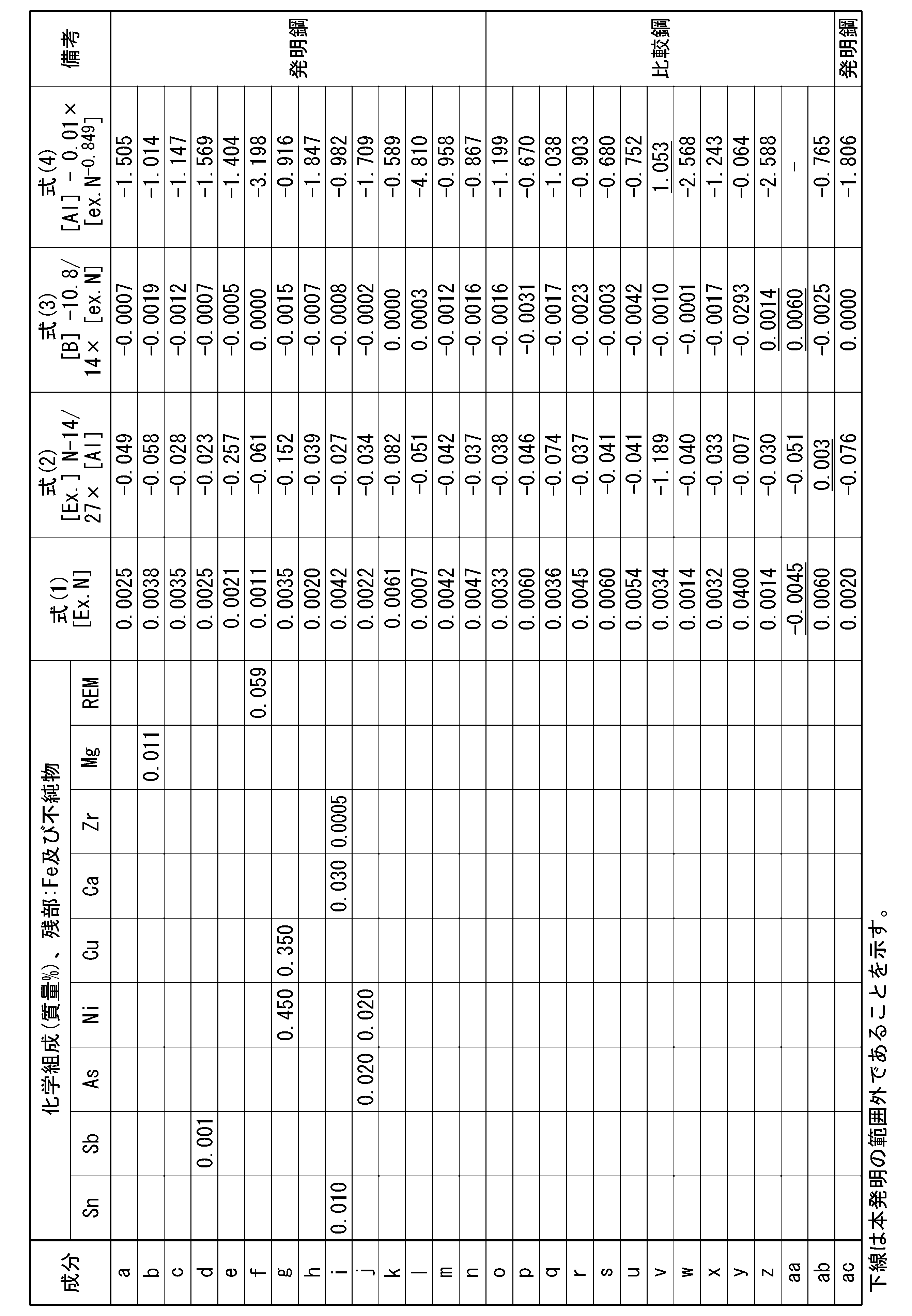


また、プレス後の圧壊特性として、曲げ戻し後の圧壊特性を評価した。鋼板にプレス加工を施し、例えばハット部材を製造した場合には、ハット部材の角部などは曲げ戻しを受け、この部分は特に亀裂の発生起点となりやすい。曲げ戻しを受けた部分において亀裂が発生しにくい場合には、プレス後の圧壊特性に優れるとみなすことができるため、プレス後の圧壊特性として曲げ戻し後の圧壊特性を評価した。
引張強さが980MPa以上であった場合、高強度を有するとして合格と判定した。一方、引張強さが980MPa未満であった場合、高強度を有さないとして不合格と判定した。
引張強さが1470MPa以上:θC>65°を合格
引張強さが1180MPa以上、1470MPa未満:θC>75°を合格
引張強さが1180MPa未満:θC>85°を合格
引張強さが1470MPa以上:5μm以下を合格
引張強さが1180MPa以上、1470MPa未満:4μm以下を合格
引張強さが1180MPa未満:3μm以下を合格
引張強さが低ければ、本実施形態が規定するような特別の考慮をせずとも、限界曲げ角度の絶対値は大きくなるとともに許容すべきボイドやき裂のサイズは小さくなる。例えば、No.23、No.26、No.28、No.35、No.39およびNo.40の比較例では、限界曲げ角度の絶対値およびボイドやき裂のサイズは、発明例に係る鋼板に引けをとらないレベルであった。しかし、これらの比較例における限界曲げ角度およびボイドやき裂のサイズは、引張強さが比較的低い鋼材であるため絶対値が良好なレベルになっているに過ぎない。

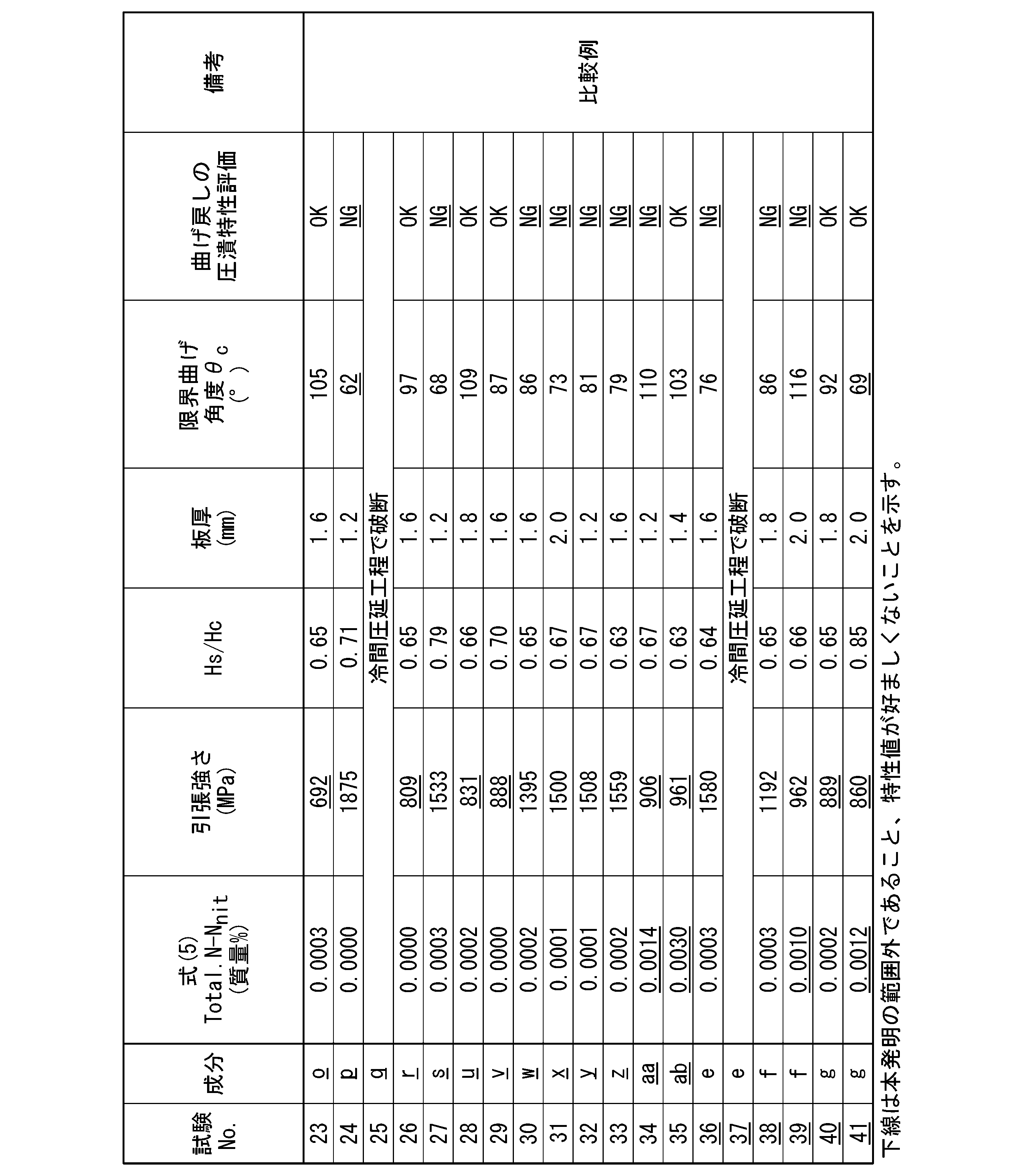
Claims (8)
- 質量%で、
C :0.07~0.25%、
Si:0.01~2.00%、
Mn:1.5~3.5%、
Al:0.001~2.000%、
B :0.0003~0.0100%、
P :0.100%以下、
S :0.0500%以下、
N :0.0005~0.0100%、
O :0.0060%以下、
Cr:0~2.000%、
Mo:0~1.000%、
W :0~1.000%、
Co:0~0.500%、
Nb:0~0.50%、
Ti:0~0.5000%、
V :0~0.500%、
Ta:0~0.100%、
Sn:0~0.050%、
Sb:0~0.050%、
As:0~0.050%、
Ni:0~1.000%、
Cu:0~1.000%、
Ca:0~0.050%、
Zr:0~0.0500%、
Mg:0~0.050%、および
REM:0~0.100%
を含有し、残部がFeおよび不純物からなる化学組成を有し、前記化学組成が下記(1)式、(2)式、(3)式、および(4)式を満たし、
前記化学組成のN含有量をTotal.Nとし、窒化物中のN含有量をNnitとしたとき、下記(5)式を満たし、
板厚方向に沿って、表面から板厚の1/4の位置である1/4深さ位置での金属組織において、面積率で、
フェライトおよびベイナイトの合計が0~60%であり、
マルテンサイトが40~100%であり、
パーライトおよび残留オーステナイトの合計が0~10%であり、
前記板厚方向に沿って、前記表面から30μmまでの領域を表層部としたとき、前記表層部において、
Bを含み短径が0.2μm以上の炭化物の数密度が0.0030個/μm2以下である、鋼板。
ex.N=[N]-[Ti]/3.4>0.0000質量%・・・(1)
ex.N-14/27×[Al]<0.000質量%・・・(2)
[B]-10.8/14×ex.N<0.0003質量%・・・(3)
[Al]-0.01×ex.N-0.849<0.000質量%・・・(4)
Total.N-Nnit≦0.0005質量%・・・(5)
上記(1)式、(2)式、(3)式および(4)式中の[N]、[Ti]、[Al]および[B]は、当該元素の質量%での含有量であり、含有しない場合は0を代入する。 - 前記表層部の金属組織において、面積率で、フェライトおよびベイナイトの合計が2%以上であり、マルテンサイト、パーライトおよび残留オーステナイトの1種又は2種以上の合計が0~98%であり、
前記表層部のビッカース硬さHsと、前記1/4深さ位置のビッカース硬さHcとの比であるHs/Hcが0.65以下である、請求項1に記載の鋼板。 - 前記表層部において、AlNの数密度が0.01個/μm2以上である、請求項1または2に記載の鋼板。
- 引張強さが980MPa以上である、請求項1または2に記載の鋼板。
- 前記化学組成が、質量%で、
Cr:0.001~2.000%、
Mo:0.010~1.000%、
W:0.001~1.000%、
Co:0.010~0.500%、
Nb:0.01~0.50%、
Ti:0.0001~0.5000%、
V:0.001~0.500%、
Ta:0.001~0.100%、
Sn:0.001~0.050%、
Sb:0.001~0.050%、
As:0.001~0.050%、
Ni:0.001~1.000%、
Cu:0.001~1.000%、
Ca:0.001~0.050%、
Zr:0.0001~0.0500%、
Mg:0.001~0.050%、および、
REM:0.001~0.100%
のうち、1種または2種以上を含有する、請求項1または2に記載の鋼板。 - 前記表面に溶融亜鉛めっき層を有する、請求項1または2に記載の鋼板。
- 前記表面に合金化溶融亜鉛めっき層を有する、請求項1または2に記載の鋼板。
- 質量%で、
C :0.07~0.25%、
Si:0.01~2.00%、
Mn:1.5~3.5%、
Al:0.001~2.000%、
B :0.0003~0.0100%、
P :0.100%以下、
S :0.0500%以下、
N :0.0005~0.0100%、
O :0.0060%以下、
Cr:0~2.000%、
Mo:0~1.000%、
W :0~1.000%、
Co:0~0.500%、
Nb:0~0.50%、
Ti:0~0.5000%、
V :0~0.500%、
Ta:0~0.100%、
Sn:0~0.050%、
Sb:0~0.050%、
As:0~0.050%、
Ni:0~1.000%、
Cu:0~1.000%、
Ca:0~0.050%、
Zr:0~0.0500%、
Mg:0~0.050%、および
REM:0~0.100%
を含有し、残部がFeおよび不純物からなる化学組成を有し、前記化学組成が下記(1)式、(2)式、(3)式、および(4)式を満たす、スラブを加熱し、950~700℃の温度域となる合計時間が5s以上となる条件で熱間圧延を施し、熱延鋼板を得る熱間圧延工程と、
前記熱間圧延工程後に、前記熱延鋼板を600~450℃の巻き取り温度で巻き取る巻き取り工程と、
前記巻き取り工程後に、前記熱延鋼板に対して、20~80%の板厚減少率で冷間圧延を施し、冷延鋼板を得る冷間圧延工程と、
前記冷間圧延工程後に、前記冷延鋼板に対して、露点が-40~20℃の雰囲気の中で、550~650℃の温度域の平均昇温速度が0.5~5.0℃/sとなるように、740~900℃の焼鈍温度まで昇温して焼鈍を施す焼鈍工程と、
を含む、鋼板の製造方法。
ex.N=[N]-[Ti]/3.4>0.0000質量%・・・(1)
ex.N-14/27×[Al]<0.000質量%・・・(2)
[B]-10.8/14×ex.N<0.0003質量%・・・(3)
[Al]-0.01×ex.N-0.849<0.000・・・(4)
上記(1)式、(2)式、(3)式および(4)式中の[N]、[Ti]、[Al]および[B]は、当該元素の質量%での含有量であり、含有しない場合は0を代入する。
Priority Applications (5)
| Application Number | Priority Date | Filing Date | Title |
|---|---|---|---|
| KR1020257018974A KR20250107887A (ko) | 2022-12-15 | 2023-12-15 | 강판 및 강판의 제조 방법 |
| MX2025006721A MX2025006721A (es) | 2022-12-15 | 2023-12-15 | Lamina de acero y metodo para fabricar la lamina de acero |
| EP23903591.8A EP4636110A4 (en) | 2022-12-15 | 2023-12-15 | SHEET STEEL, AND METHOD FOR MANUFACTURED IT |
| JP2024564445A JPWO2024128312A1 (ja) | 2022-12-15 | 2023-12-15 | |
| CN202380085101.0A CN120359314A (zh) | 2022-12-15 | 2023-12-15 | 钢板及钢板的制造方法 |
Applications Claiming Priority (2)
| Application Number | Priority Date | Filing Date | Title |
|---|---|---|---|
| JP2022200162 | 2022-12-15 | ||
| JP2022-200162 | 2022-12-15 |
Publications (1)
| Publication Number | Publication Date |
|---|---|
| WO2024128312A1 true WO2024128312A1 (ja) | 2024-06-20 |
Family
ID=91485865
Family Applications (1)
| Application Number | Title | Priority Date | Filing Date |
|---|---|---|---|
| PCT/JP2023/045025 Ceased WO2024128312A1 (ja) | 2022-12-15 | 2023-12-15 | 鋼板および鋼板の製造方法 |
Country Status (6)
| Country | Link |
|---|---|
| EP (1) | EP4636110A4 (ja) |
| JP (1) | JPWO2024128312A1 (ja) |
| KR (1) | KR20250107887A (ja) |
| CN (1) | CN120359314A (ja) |
| MX (1) | MX2025006721A (ja) |
| WO (1) | WO2024128312A1 (ja) |
Cited By (2)
| Publication number | Priority date | Publication date | Assignee | Title |
|---|---|---|---|---|
| WO2026070019A1 (ja) * | 2024-09-27 | 2026-04-02 | Jfeスチール株式会社 | 鋼板及び部材、並びに、それらの製造方法 |
| WO2026070020A1 (ja) * | 2024-09-27 | 2026-04-02 | Jfeスチール株式会社 | 鋼板及び部材、並びに、それらの製造方法 |
Citations (5)
| Publication number | Priority date | Publication date | Assignee | Title |
|---|---|---|---|---|
| WO2015093043A1 (ja) * | 2013-12-18 | 2015-06-25 | Jfeスチール株式会社 | 高強度溶融亜鉛めっき鋼板及びその製造方法 |
| WO2016120914A1 (ja) * | 2015-01-30 | 2016-08-04 | Jfeスチール株式会社 | 高強度めっき鋼板およびその製造方法 |
| JP2017520681A (ja) * | 2014-06-06 | 2017-07-27 | アルセロールミタル | 高強度多相鋼、製造方法および使用 |
| WO2020196060A1 (ja) | 2019-03-28 | 2020-10-01 | 日本製鉄株式会社 | 高強度鋼板 |
| WO2022080497A1 (ja) * | 2020-10-15 | 2022-04-21 | 日本製鉄株式会社 | 鋼板およびその製造方法 |
Family Cites Families (3)
| Publication number | Priority date | Publication date | Assignee | Title |
|---|---|---|---|---|
| JPH04202711A (ja) * | 1990-11-30 | 1992-07-23 | Kobe Steel Ltd | ドア補強パイプ用高強度薄鋼板の製造方法 |
| WO2020262651A1 (ja) * | 2019-06-28 | 2020-12-30 | 日本製鉄株式会社 | 鋼板 |
| EP4296396A4 (en) * | 2021-03-31 | 2024-08-07 | Nippon Steel Corporation | Steel plate, method for producing steel plate, and method for producing intermediate steel plate |
-
2023
- 2023-12-15 EP EP23903591.8A patent/EP4636110A4/en active Pending
- 2023-12-15 KR KR1020257018974A patent/KR20250107887A/ko active Pending
- 2023-12-15 CN CN202380085101.0A patent/CN120359314A/zh active Pending
- 2023-12-15 MX MX2025006721A patent/MX2025006721A/es unknown
- 2023-12-15 WO PCT/JP2023/045025 patent/WO2024128312A1/ja not_active Ceased
- 2023-12-15 JP JP2024564445A patent/JPWO2024128312A1/ja active Pending
Patent Citations (5)
| Publication number | Priority date | Publication date | Assignee | Title |
|---|---|---|---|---|
| WO2015093043A1 (ja) * | 2013-12-18 | 2015-06-25 | Jfeスチール株式会社 | 高強度溶融亜鉛めっき鋼板及びその製造方法 |
| JP2017520681A (ja) * | 2014-06-06 | 2017-07-27 | アルセロールミタル | 高強度多相鋼、製造方法および使用 |
| WO2016120914A1 (ja) * | 2015-01-30 | 2016-08-04 | Jfeスチール株式会社 | 高強度めっき鋼板およびその製造方法 |
| WO2020196060A1 (ja) | 2019-03-28 | 2020-10-01 | 日本製鉄株式会社 | 高強度鋼板 |
| WO2022080497A1 (ja) * | 2020-10-15 | 2022-04-21 | 日本製鉄株式会社 | 鋼板およびその製造方法 |
Non-Patent Citations (1)
| Title |
|---|
| See also references of EP4636110A1 |
Cited By (2)
| Publication number | Priority date | Publication date | Assignee | Title |
|---|---|---|---|---|
| WO2026070019A1 (ja) * | 2024-09-27 | 2026-04-02 | Jfeスチール株式会社 | 鋼板及び部材、並びに、それらの製造方法 |
| WO2026070020A1 (ja) * | 2024-09-27 | 2026-04-02 | Jfeスチール株式会社 | 鋼板及び部材、並びに、それらの製造方法 |
Also Published As
| Publication number | Publication date |
|---|---|
| MX2025006721A (es) | 2025-07-01 |
| EP4636110A1 (en) | 2025-10-22 |
| EP4636110A4 (en) | 2026-04-22 |
| CN120359314A (zh) | 2025-07-22 |
| KR20250107887A (ko) | 2025-07-14 |
| JPWO2024128312A1 (ja) | 2024-06-20 |
Similar Documents
| Publication | Publication Date | Title |
|---|---|---|
| CN113330133B (zh) | 热浸镀锌钢板及其制造方法 | |
| KR102527545B1 (ko) | 고강도 강판 | |
| CN112074620B (zh) | 镀锌钢板及其制造方法 | |
| KR102387095B1 (ko) | 고강도 냉연 강판 및 그의 제조 방법 | |
| KR102418275B1 (ko) | 고강도 냉연 강판 및 그의 제조 방법 | |
| KR102433938B1 (ko) | 고강도 냉연강판, 고강도 도금강판 및 그것들의 제조방법 | |
| JP6822488B2 (ja) | 鋼板 | |
| WO2018026014A1 (ja) | 鋼板及びめっき鋼板 | |
| WO2020162560A1 (ja) | 溶融亜鉛めっき鋼板およびその製造方法 | |
| WO2015046339A1 (ja) | 延性および低温靭性に優れた高強度鋼板、並びにその製造方法 | |
| CN111344423A (zh) | 高强度冷轧钢板 | |
| JPWO2020195605A1 (ja) | 鋼板、鋼板の製造方法およびめっき鋼板 | |
| KR102274284B1 (ko) | 고강도 냉연 강판 및 그의 제조 방법 | |
| KR20220129615A (ko) | 강판, 부재 및 그들의 제조 방법 | |
| KR20230109161A (ko) | 강판, 부재 및 그것들의 제조 방법 | |
| WO2024128312A1 (ja) | 鋼板および鋼板の製造方法 | |
| KR20220129616A (ko) | 강판, 부재 및 그들의 제조 방법 | |
| US12331378B2 (en) | Steel sheet and method for producing same | |
| JP7640906B2 (ja) | 高強度鋼板 | |
| CN114945690A (zh) | 钢板及其制造方法 | |
| WO2022138895A1 (ja) | 鋼板、部材およびそれらの製造方法 | |
| KR102930683B1 (ko) | 핫 스탬프 성형체 | |
| KR20240025615A (ko) | 강판 및 그 제조 방법 | |
| JP7191796B2 (ja) | 高強度鋼板およびその製造方法 | |
| KR20240133736A (ko) | 냉연 강판 및 그 제조 방법 |
Legal Events
| Date | Code | Title | Description |
|---|---|---|---|
| 121 | Ep: the epo has been informed by wipo that ep was designated in this application |
Ref document number: 23903591 Country of ref document: EP Kind code of ref document: A1 |
|
| WWE | Wipo information: entry into national phase |
Ref document number: 2024564445 Country of ref document: JP |
|
| WWE | Wipo information: entry into national phase |
Ref document number: 202517053341 Country of ref document: IN |
|
| WWE | Wipo information: entry into national phase |
Ref document number: 1020257018974 Country of ref document: KR |
|
| WWE | Wipo information: entry into national phase |
Ref document number: 202380085101.0 Country of ref document: CN |
|
| WWE | Wipo information: entry into national phase |
Ref document number: 2501003838 Country of ref document: TH |
|
| WWP | Wipo information: published in national office |
Ref document number: 1020257018974 Country of ref document: KR |
|
| WWE | Wipo information: entry into national phase |
Ref document number: 2023903591 Country of ref document: EP |
|
| NENP | Non-entry into the national phase |
Ref country code: DE |
|
| WWP | Wipo information: published in national office |
Ref document number: 202517053341 Country of ref document: IN |
|
| ENP | Entry into the national phase |
Ref document number: 2023903591 Country of ref document: EP Effective date: 20250715 |
|
| WWP | Wipo information: published in national office |
Ref document number: 202380085101.0 Country of ref document: CN |
|
| WWP | Wipo information: published in national office |
Ref document number: 2023903591 Country of ref document: EP |