WO2024134751A1 - ガイドワイヤ - Google Patents
ガイドワイヤ Download PDFInfo
- Publication number
- WO2024134751A1 WO2024134751A1 PCT/JP2022/046822 JP2022046822W WO2024134751A1 WO 2024134751 A1 WO2024134751 A1 WO 2024134751A1 JP 2022046822 W JP2022046822 W JP 2022046822W WO 2024134751 A1 WO2024134751 A1 WO 2024134751A1
- Authority
- WO
- WIPO (PCT)
- Prior art keywords
- section
- guidewire
- rear end
- coil
- core shaft
- Prior art date
- Legal status (The legal status is an assumption and is not a legal conclusion. Google has not performed a legal analysis and makes no representation as to the accuracy of the status listed.)
- Ceased
Links
Images


Classifications
-
- A—HUMAN NECESSITIES
- A61—MEDICAL OR VETERINARY SCIENCE; HYGIENE
- A61M—DEVICES FOR INTRODUCING MEDIA INTO, OR ONTO, THE BODY; DEVICES FOR TRANSDUCING BODY MEDIA OR FOR TAKING MEDIA FROM THE BODY; DEVICES FOR PRODUCING OR ENDING SLEEP OR STUPOR
- A61M25/00—Catheters; Hollow probes
- A61M25/01—Introducing, guiding, advancing, emplacing or holding catheters
- A61M25/09—Guide wires
- A61M2025/09058—Basic structures of guide wires
- A61M2025/09083—Basic structures of guide wires having a coil around a core
-
- A—HUMAN NECESSITIES
- A61—MEDICAL OR VETERINARY SCIENCE; HYGIENE
- A61M—DEVICES FOR INTRODUCING MEDIA INTO, OR ONTO, THE BODY; DEVICES FOR TRANSDUCING BODY MEDIA OR FOR TAKING MEDIA FROM THE BODY; DEVICES FOR PRODUCING OR ENDING SLEEP OR STUPOR
- A61M25/00—Catheters; Hollow probes
- A61M25/01—Introducing, guiding, advancing, emplacing or holding catheters
- A61M25/09—Guide wires
- A61M2025/09108—Methods for making a guide wire
-
- A—HUMAN NECESSITIES
- A61—MEDICAL OR VETERINARY SCIENCE; HYGIENE
- A61M—DEVICES FOR INTRODUCING MEDIA INTO, OR ONTO, THE BODY; DEVICES FOR TRANSDUCING BODY MEDIA OR FOR TAKING MEDIA FROM THE BODY; DEVICES FOR PRODUCING OR ENDING SLEEP OR STUPOR
- A61M25/00—Catheters; Hollow probes
- A61M25/01—Introducing, guiding, advancing, emplacing or holding catheters
- A61M25/09—Guide wires
- A61M2025/0915—Guide wires having features for changing the stiffness
-
- A—HUMAN NECESSITIES
- A61—MEDICAL OR VETERINARY SCIENCE; HYGIENE
- A61M—DEVICES FOR INTRODUCING MEDIA INTO, OR ONTO, THE BODY; DEVICES FOR TRANSDUCING BODY MEDIA OR FOR TAKING MEDIA FROM THE BODY; DEVICES FOR PRODUCING OR ENDING SLEEP OR STUPOR
- A61M25/00—Catheters; Hollow probes
- A61M25/01—Introducing, guiding, advancing, emplacing or holding catheters
- A61M25/09—Guide wires
- A61M2025/09175—Guide wires having specific characteristics at the distal tip
Definitions
- the present invention relates to a guidewire.
- Patent Document 1 describes a guidewire in which the tip side of a core shaft made of a superelastic alloy is heat-treated.
- General guidewires are sometimes "shaped" by bending the tip of the guidewire into a specific shape to fit the shape of blood vessels, etc.
- Guidewires that use a core shaft made of a superelastic material had room for improvement in "shaping performance,” which indicates the ease of shaping.
- shapeing performance indicates the ease of shaping.
- hook shaping in which 1 to 2 millimeters of the tip of the guidewire are shaped into a hook at an angle of approximately 45 degrees.
- improvements in shaping performance were required, there was also room for improvement in the durability of the guidewire against breakage, such as bending the guidewire while in use.
- the present invention aims to provide a guidewire that has excellent shaping performance and durability, and can be easily shaped into a hook.
- the present invention has been made to solve at least some of the problems described above, and can be realized in the following form.
- One embodiment of the present invention is a guidewire comprising a core shaft made of a superelastic material and a coil formed of strands wound in a spiral shape around the outer periphery of the tip of the core shaft, the core shaft having a first section on the inside of the coil, the first section being made of a thermally modified portion formed by thermally modifying the superelastic material, and a second section located on the rear end side of the first section, the second section either having a thermally modified portion of a shorter length than the first section or not having a thermally modified portion, and the coil having a sparsely wound section at the tip with gaps formed between adjacent strands.
- the provision of the first section consisting of a heat-modified portion suppresses the superelastic properties of the core shaft, improving shaping performance. Furthermore, the provision of a sparsely wound portion at the tip of the coil improves the shaping performance at the tip of the guidewire. This makes it easy to give it a hook shape. Furthermore, the second section is provided with either a heat-modified portion that is shorter in length than the heat-modified portion at the tip, or a portion that is not heat-modified, thereby maintaining the superelasticity of the core shaft and the durability of the guidewire.
- the size of the gap between the wires of the sparsely wound portion in the longitudinal direction of the coil may be equal to or greater than the outer diameter of the wires.
- the length of the fixing portion can be shortened.
- the rear end of the first section may be located rearward of the rear end of the openly coiled portion.
- a "body shape” When shaping a guidewire, a "body shape” may be applied, which is a gently curved shape.
- the first section which is made of a heat-denatured portion, extends over a wider area, making it easier to apply the body shape.
- the rear end of the first section and the rear end of the sparsely coiled section are located at different positions in the longitudinal direction, making it possible to make the change in bending rigidity of the guidewire more gradual.
- the rear end of the openly wound portion may be located rearward of the rear end of the first section.
- the openly coiled portion at the tip side extends over a wider range, making it easier to shape the body.
- the rear end of the openly coiled portion and the rear end of the first section are located at different positions in the longitudinal direction, making it possible to make the change in bending stiffness of the guidewire more gradual.
- the coil further has an openly wound portion at the rear end in which gaps are formed between adjacent strands of wire, and the size of the gaps between the strands of wire in the openly wound portion at the rear end in the longitudinal direction of the coil may be equal to or greater than the outer diameter of the strands of wire.
- the length of the fixing portion can be shortened.
- the present invention can be realized in various forms, such as a guidewire, a method for manufacturing a guidewire, a method for manufacturing a catheter, an endoscope, a dilator, etc.
- FIG. 1 is an explanatory diagram illustrating an example of an overall configuration of a guidewire according to a first embodiment
- 1 is an explanatory diagram illustrating a longitudinal cross section of a distal end portion of a guidewire.
- FIG. FIG. 2 is an explanatory diagram illustrating the AA cross section of the guidewire.
- 1 is an explanatory diagram illustrating a longitudinal cross section of the distal end of a guidewire.
- FIG. 4 is an explanatory diagram illustrating a vertical cross section of a rear end portion of the coil.
- FIG. 13 is an explanatory diagram illustrating a longitudinal cross section of a distal end portion of a guidewire according to a third embodiment.
- FIG. 13 is an explanatory diagram illustrating a longitudinal cross section of a distal end portion of a guidewire according to a fourth embodiment.
- FIG. 1 is an explanatory diagram illustrating a hook-shaped tip of a guide wire.
- FIG. 13 is an explanatory diagram illustrating a guide wire according to a first modified example.
- 13 is an explanatory diagram illustrating a guide wire according to a fourth modified example.
- FIG. 13 is an explanatory diagram illustrating a guide wire according to modification 8.
- the sizes of the components of the guidewire 1A of the first embodiment shown in Figures 1 to 6 are illustrative and may be expressed on a scale different from the actual size.
- the end of each component of the guidewire 1A located on the tip side will be referred to as the "tip”, and the part including the “tip” and extending from the tip to the middle toward the rear end will be referred to as the "tip portion”.
- the end of each component located on the rear end side will be referred to as the "rear end”
- the part including the "rear end” and extending from the rear end to the middle toward the tip side will be referred to as the "rear portion”.
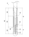
- FIG. 1 is an explanatory diagram illustrating an overall view of a guidewire 1A of a first embodiment.
- the guidewire 1A is a medical device used for treating blood vessels, etc.
- the guidewire 1A has a core shaft 10, a coil 20A, a tip fixing portion 30, and a rear end fixing portion 31.
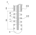
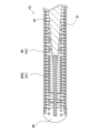
- FIG. 2 is an explanatory diagram illustrating a longitudinal cross section of the tip of the guidewire 1A of the first embodiment.
- the core shaft 10 is a long member extending from the tip to the rear end of the guidewire 1A.
- the core shaft 10 is formed so that the outer diameter decreases toward the tip, and the tip has a straight section 11 with a substantially constant outer diameter in the longitudinal direction, and a tapered section 12 provided on the rear end side of the straight section 11. Details of the core shaft 10 will be described later.
- the core shaft 10 is made of a superelastic material.
- the coil 20A is a member formed of wire 21A wound in a spiral shape to cover the outer periphery of the tip of the core shaft 10.
- the coil 20A has, in order from the tip, a loosely wound section 22A, a densely wound section 23A, and a loosely wound section 24A.
- the densely wound section 23A is a section with a small pitch where the wires 21A are wound so that they come into contact with each other.
- the loosely wound section 22A and the loosely wound section 24A have a larger pitch than the densely wound section 23A, and a gap G (FIGS. 4 and 5) is formed between adjacent wires 21A, as described below.
- the coil 20A has the densely wound section 23A and the loosely wound section 24A on the rear end side of the loosely wound section 22A, but the entire length of the coil 20A may be composed of the loosely wound section 22A. Alternatively, the entire rear end side of the coil 20A from the loosely wound section 22A may be the densely wound section 23A.
- the configuration of the loosely wound section 22A of the coil 20A is not limited to the above example, and various modifications are possible. Details of openly wound portion 22A and openly wound portion 24A will be described later.
- the material of the coil 20A is not particularly limited, but examples that can be used include stainless steel (SUS302, SUS304, SUS316, etc.), superelastic alloys such as Ni-Ti alloys, piano wire, nickel-chromium alloys, cobalt alloys, tungsten, platinum, etc.
- stainless steel SUS302, SUS304, SUS316, etc.
- superelastic alloys such as Ni-Ti alloys, piano wire, nickel-chromium alloys, cobalt alloys, tungsten, platinum, etc.
- the tip fixing part 30 is a member that fixes the tip of the core shaft 10 and the tip of the coil 20A.
- the rear end fixing part 31 is a member that fixes the middle part of the core shaft 10 and the rear end of the coil 20A.
- the tip fixing part 30 and the rear end fixing part 31 are formed by applying molten brazing material or solder material to the core shaft 10 and the coil 20A and then cooling and solidifying them.
- the material of the tip fixing portion 30 and the rear end fixing portion 31 is not particularly limited, but for example, solder material (aluminum alloy solder, silver solder, gold solder, etc.), metal solder (Ag-Sn alloy, Au-Sn alloy, etc.), adhesive (epoxy adhesive, etc.), etc. can be used.
- the core shaft 10 has a first section S1 and a second section S2 inside the coil 20A.
- the first section extends from the tip of the core shaft 10 toward the rear end side, and is made of a heat-modified section 13A.
- the part of the core shaft 10 that is not heat-modified other than the heat-modified section 13A is called the "non-heat-modified section 15A".
- the heat-modified section 13A is a part in which the characteristics of the superelastic material forming the core shaft 10 are changed by heating the core shaft 10.
- the heat-modified section 13A is a part in which the superelastic characteristics of the core shaft 10 are suppressed more than those of the non-heat-modified section 15A.
- the rear end 14A (rear end of the heat-modified section 13A) of the first section S1 indicates the boundary between the heat-modified section 13A and the non-heat-modified section 15A.
- the rear end 14A of the first section S1 is located on the rear end side of the rear end 25A of the loosely wound section 22A described later.
- the rear end 14A of the first section S1 and the rear end 25A of the open coil portion 22A on the tip side are provided at different positions in the longitudinal direction of the core shaft 10.
- the length in the longitudinal direction from the tip to the rear end 14A of the first section S1 is shown as Ls1.
- the length Ls1 of the first section is not particularly limited, but may be, for example, 2 to 7 millimeters.
- the second section S2 is located inside the coil 20A and is located closer to the rear end than the first section S1.
- the second section S2 does not have a thermally denatured portion 13A and is formed only by a non-thermally denatured portion 15A.
- the second section S2 does not have a thermally denatured portion 13A, but the second section S2 may have a thermally denatured portion 13A formed therein as in the second embodiment described below.
- the length in the major axis direction of the thermally denatured portion 13A formed in the second section S2 is shorter than the length of the thermally denatured portion 13A in the first section S1.
- the method for producing the thermally modified portion 13A is not particularly limited, but for example, the thermally modified portion 13A can be formed by irradiating the surface of the core shaft 10 with a laser to heat the core shaft 10 to approximately 600 degrees to approximately 1000 degrees.
- FIG. 3 is an explanatory diagram illustrating an example of an A-A cross section of the guide wire 1A of the first embodiment.
- the straight portion 11 of the core shaft 10 is formed by a plane 16, a plane 17 facing the plane 16, and a curved surface 18 and a curved surface 19 connecting the planes 16 and 17.
- the cross section of the straight portion 11 has a flat shape that extends long in a predetermined direction.
- the length of the cross section of the straight portion 11 in the direction Dx parallel to the plane 16 is greater than the length of the direction Dy perpendicular to the plane 16.
- the straight portion 11 is more likely to bend depending on the direction of the stress to which the straight portion 11 is subjected.
- the straight portion 11 is more likely to bend when stress is applied to the straight portion 11 in the direction Dy perpendicular to the plane 16 than when stress is applied to the straight portion 11 in the direction Dx parallel to the plane 16.
- the length of the straight portion 11 in the longitudinal direction of the guide wire 1A is not particularly limited, but can be, for example, 10 to 20 millimeters.
- the cross section of the tapered portion 12 and the portion of the core shaft 10 rearward of the tapered portion 12 are circular.
- the method for producing the straight section 11 is not particularly limited, but for example, it can be produced by pressing the tip of the core shaft 10, which is formed into a cylindrical shape, using a die with a flat surface.
- ⁇ Details of the open coil portion 22A on the tip side> 4 is an explanatory diagram illustrating a longitudinal section of the tip of the guidewire 1A of the first embodiment.
- the openly coiled portion 22A will be described in detail.
- the coil 20A has an openly coiled portion 22A in which a gap G is provided between adjacent wires 21A among the wires 21A wound in a spiral shape.
- the openly coiled portion 22A is formed from the tip to the rear end side of the coil 20A, and its tip is embedded in the tip fixing portion 30.
- the rear end 25A of the openly coiled portion 22A indicates the boundary between the openly coiled portion 22A and the densely coiled portion 23A.
- the length of the openly coiled portion 22A in the major axis direction is not limited, but can be, for example, about 0.5 to 2 millimeters.
- the size Lg of the gap G between the wires 21A is equal to or larger than the outer diameter D of the wire 21A.
- the outer diameter D of the wire 21A refers to the size of the wire 21A in the long axis direction of the coil 20A.
- the outer diameter D of the wire 21A is defined as "the size in the long axis direction of the part of the wire 21A that is the largest in the long axis direction of the coil 20A.” In other words, the outer diameter D is the maximum outer diameter of the wire 21A.
- the configuration in which the size Lg of the gap G and the outer diameter D of the wire 21A are approximately the same can be rephrased as a configuration in which the pitch of the openly wound portion 22A is approximately 200% when the pitch of the densely wound portion 23A, in which the wires 21A are wound so as to be in contact with each other, is 100%. Therefore, "the size Lg of the gap G is equal to or larger than the outer diameter D of the wire 21A" can be rephrased as "the pitch of the openly wound portion 22A is 200% or more when the pitch of the densely wound portion 23A is 100%.
- FIG. 5 is an explanatory diagram illustrating a longitudinal section of the rear end of the coil 20A of the guide wire 1A of the first embodiment. The details of the openly coiled portion 24A will be described.
- the openly coiled portion 24A is formed at the rear end of the coil 20A.
- the openly coiled portion 24A is formed from the rear end of the coil 20A toward the tip end, and the rear end is embedded in the rear end fixing portion 31.
- a gap G is formed between adjacent wires 21A, similar to the openly coiled portion 22A formed at the tip end described above.
- the length of the openly coiled portion 24A in the major axis direction is not limited, but can be, for example, about 0.5 to 2 millimeters.
- the pitch size of the densely coiled portion 23A is 100%
- the pitch size of the openly coiled portion 24A described in FIG. 5 is 200% or more.
- the size Lg of the gap G between the open coiled portion 22A and the open coiled portion 24A is set to be equal to or larger than the outer diameter D of the wire 21A, but the size Lg of the gap G between the open coiled portion 22A and the open coiled portion 24A may be smaller than the outer diameter D of the wire 21A.
- the pitch of the densely coiled portion 23A is set to 100%
- the size of the pitch of the open coiled portion 22A and the open coiled portion 24A can be set to approximately 150% to 500%.
- the size of the pitch of the open coiled portion 22A and the open coiled portion 24A is set to approximately 150% or more, adjacent wires 21A are sufficiently separated, and the thermal conductivity between the wires 21A is reduced.
- the amount of molten brazing material or solder material that flows along the wire 21A in the longitudinal direction can be reduced.
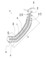
- FIG. 6 is an explanatory diagram illustrating the shaped tip of guidewire 1A.
- the hook-shaped shape of about 1 to 2 mm of the tip of guidewire 1A at an angle of about 45 degrees is called “hook shape”
- the gently curved shape of about 20 mm of the tip of guidewire 1A is called “body shape”.
- the hook-shaped part is shown as hook-shaped part Sa
- the body-shaped part is shown as body-shaped part Sb.
- Hook-shaped part Sa is a part where heat-modified part 13A and loosely wound part 22A overlap.
- Heat-modified part 13A is also provided in body-shaped part Sb.
- the cross section of straight part 11 has a flat shape, it has a direction that is easy to bend.
- guidewire 1A has a part that is easiest to shape at the tip, and a part that is easy to shape is also provided on the rear end side of the tip. In other words, the ease of shaping of the guidewire 1A changes stepwise from the tip to the rear end.
- the guidewire 1A has a first section S1 consisting of a thermally modified portion 13A.
- the thermally modified portion 13A has reduced superelastic properties compared to the non-thermally modified portion 15A, so the force that tries to return to the original shape when deformed is reduced. This makes it easy to shape the guidewire 1A in the intended direction.
- the guidewire 1A has a sparsely wound portion 22A, and the size Lg of the gap G between adjacent strands 21A is equal to or larger than the outer diameter D of the strands 21A.
- the pitch of a coil in a typical guidewire is about 100% to about 120%
- the pitch of the sparsely wound portion 22A is wider than 200%. Since adjacent strands 21A in the sparsely wound portion 22A are sufficiently spaced apart, the thermal conductivity between the strands 21A is reduced. As a result, when a brazing material or solder material is used in the tip fixing portion 30, the amount of molten brazing material or solder material that flows along the strands 21A in the longitudinal direction can be reduced.
- the length of the tip fixing portion 30 in the longitudinal direction can be shortened, and the flexibility of the tip of the guidewire 1A can be improved.
- the tip of the guidewire 1A can be made flexible, making it easier for the user of the guidewire 1A to shape it in the direction intended.
- the length of the loosely coiled portion 22A in the longitudinal direction is about 1 to 2 millimeters, it becomes easy to form a hook shape of about 1 to 2 millimeters.
- the rear end 14A of the first section S1 is located rearward of the rear end 25A of the loosely wound portion 22A. This allows the portion of the core shaft 10 that is easy to shape to be more widely arranged, making it easier to perform body shaping. For example, by setting the longitudinal length Ls1 (FIG. 2) of the first section S1 to about 20 millimeters, it becomes easy to perform body shaping of about 20 millimeters. By performing body shaping, even when the guide wire 1A is inserted into a branching portion of a blood vessel with a large blood vessel diameter (for example, a blood vessel with a diameter of about 2 to 10 millimeters), the user of the guide wire 1A can easily advance the guide wire 1A in the intended direction.
- a large blood vessel diameter for example, a blood vessel with a diameter of about 2 to 10 millimeters
- the heat-denatured portion 13A is provided at the tip portion of the body shaping portion Sb, which is more likely to deform when shaping, making body shaping easier.
- the length of the second section S2 becomes relatively longer, improving the durability of the core shaft 10 against bending and breaking, making it easier to achieve both shaping performance and durability.
- the rear end 14A of the first section S1 is positioned rearward of the rear end 25A of the sparsely wound portion 22A, the rear end 14A of the first section S1 and the rear end 25A of the sparsely wound portion 22A on the tip side are located at different positions in the longitudinal direction of the core shaft 10.
- the change in bending rigidity of the core shaft 10 at the boundary between the thermally modified portion 13A and the non-thermally modified portion 15A and the change in bending rigidity of the coil 20A at the boundary between the sparsely wound portion 22A and the densely wound portion 23A (rear end 15A of the sparsely wound portion 22A) occur at different positions. This makes it possible to suppress a sudden change in bending rigidity in the longitudinal direction of the guidewire 1A.
- the second section S2 does not have a heat-modified portion 13A, and is formed only from a non-heat-modified portion 15A. This allows the superelastic properties of the core shaft 10 to be maintained in the second section S2, and prevents the guidewire 1A from unintentionally breaking or bending. As a result, the shaping performance of the guidewire 1A can be improved, and the durability of the guidewire 1A can be increased.
- the coil 20A has a sparsely wound portion 24A at the rear end, and the size Lg of the gap G between adjacent wires 21A is equal to or larger than the outer diameter D of the wires 21A. While the coil pitch of a typical guidewire is 100% to 120%, the pitch of the sparsely wound portion 24A is expanded to 200% or more. As a result, similar to the sparsely wound portion 22A described above, the adjacent wires 21A are sufficiently spaced apart in the sparsely wound portion 24A, so that the thermal conductivity between the wires 21A is reduced.
- the longitudinal length of the rear end fixing portion 31 can be shortened, and the flexibility of the guidewire 1A can be improved. This makes it possible to suppress an increase in bending stiffness occurring near the rear end fixing part 31 of the guidewire 1A, and reduces the possibility of breakage, such as bending or bending, of the guidewire 1A occurring near the rear end fixing part 31.
- the cross section of the straight portion 11 of the core shaft 10 has a flattened shape that extends long in a predetermined direction. As a result, the straight portion 11 bends in a different direction depending on the direction of the stress it receives.
- the straight portion 11 bends in the direction in which it bends easily, so that the guidewire 1A can be bent uniformly in a certain direction. In this embodiment, it is easy to bend and shape the tip of the guidewire 1A uniformly in the Dy direction shown in FIG. 3.
- the bendability is constant regardless of the direction, so it is difficult to bend the guidewire 1A uniformly in a certain direction, and there is a high possibility that the guidewire 1A will be shaped so as to be twisted.
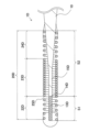
- Second Embodiment 7 is an explanatory diagram illustrating a longitudinal cross section of a distal end portion of a guidewire 1B of the second embodiment.
- the guidewire 1B is different from the guidewire 1A of the first embodiment in that a thermally denatured portion 13B is provided in the second section S2. Description of the configuration of the guidewire 1B that is common to the guidewire 1A will be omitted.
- a thermally denatured portion 13B is provided in a portion of the second section S2, and a non-thermally denatured portion 15B is provided in the portion other than the thermally denatured portion 13B.
- the length Ls2 in the long axis direction of the thermally denatured portion 13B provided in the second section S2 is shorter than the length Ls1 in the long axis direction of the first section S1.
- the longitudinal length Ls2 of the thermally modified portion 13B provided in the second section S2 is shorter than the longitudinal length Ls1 of the first section S1, thereby improving the durability of the core shaft 10 against breaking or bending.
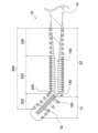
- Third Embodiment 8 is an explanatory diagram illustrating a longitudinal cross section of a distal end portion of a guidewire 1B of the third embodiment.
- the guidewire 1C is different from the guidewire 1A of the first embodiment in that a rear end 25C of the openly coiled portion 22C is located further rearward than a rear end 14C of the first section S1.
- a description of the configuration of the guidewire 1C that is common to the guidewire 1A will be omitted.
- the guidewire 1C is easy to shape the body because the openly coiled portion 22C extends further toward the rear end and is provided over a wide range. Also in this embodiment, the rear end 14C of the first section S1 and the rear end 25C of the openly coiled portion 22C on the tip side are provided at different positions in the longitudinal direction of the core shaft 10. This makes it possible to suppress a sudden change in bending rigidity that occurs when the position where the bending rigidity of the core shaft 10 changes overlaps with the position where the bending rigidity of the coil 20C changes.
- Fourth Embodiment 9 is an explanatory diagram illustrating a longitudinal cross section of a distal end portion of a guidewire 1D of the fourth embodiment.
- the guidewire 1D is different from the guidewire 1A of the fourth embodiment in that a rear end 14D of the first section S1 and a rear end 25D of the openly coiled portion 22D are located at substantially the same position in the longitudinal direction of the coil 20C. Description of the configuration of the guidewire 1D that is common to the guidewire 1A will be omitted.
- the heat-modified portion 13D and the loosely wound portion 22A make it easy to form a hook shape. Even in a configuration in which the heat-modified portion 13D does not extend further rearward than the rear end 25D of the loosely wound portion 22D as in this embodiment, the core shaft 10 has a straight portion 11 with a flattened cross-sectional shape, making it easy to give it a body shape. Furthermore, by setting the heat-modified portion 13D to be short, it is possible to ensure a wider range over which the durability of the core shaft 10 is maintained.
- FIG. 10 is an explanatory diagram illustrating the tip of the guidewire 1D of the fourth embodiment that has been hook-shaped.
- the portion that has been given the hook shape is shown as the hook-shaped portion Sa.
- the portion where the thermally denatured portion 13D and the loosely wound portion 22D are overlapping is easy to shape, so that the hook shape can be easily formed.
- FIG. 11 is an explanatory diagram illustrating a guidewire 1E of the first modification.
- the guidewire 1E is different from the guidewires of the respective embodiments in the position of the rear end 14E of the first section S1.
- the rear end 14A of the first section S1 is located rearward of the rear end 25E of the openly coiled section 22A, and is formed over the entire length of the straight section 11.
- the rear end 14E of the first section S1 may be located rearward of the rear end 25E of the openly coiled section 22E, and may be provided in the middle of the straight section 11.
- the hook shape can be easily formed by the thermally modified section 13E and the openly coiled section 22E.
- the straight section 11 can uniformly form the body shape in a predetermined direction. Furthermore, by setting the thermally modified section 13E to be short, the durability of the core shaft 10 can be maintained over a wider range.
- the first section S1 is formed from the tip of the core shaft 10 toward the rear end, but it does not have to be formed from the tip of the core shaft 10.
- the first section S1 only needs to be formed inside the coil (20A, 20B, 20C, 20D), and for example, the tip of the first section S1 may be provided on the rear end side of the tip of the core shaft 10.
- the first section S1 and the second section S2 may have a portion in which the characteristics of the core shaft 10 are changed other than the thermally modified portions (13A, 13B, 13C, 13D).
- a portion in which the surface state of the core shaft 10 is changed by electrolytic polishing, shot peening, or the like may be provided.
- ⁇ Modification 4> 12 is an explanatory diagram illustrating a guidewire 1F of Modification 4.
- the guidewire 1F has a plurality of thermally denatured portions 13F in the second section S2. As in the guidewire 1F, two thermally denatured portions 13F may be provided in the second section S2.
- the cross section of the wires (21A, 21B, 21C, 21D) is circular, but it may be rectangular, such as square or oblong.
- the coils (20A, 20B, 20C, 20D) are formed of one wire (21A, 21B, 21C, 21D), but the coils may be formed by winding a plurality of wires (21A, 21B, 21C, 21D) in a spiral shape.
- the outer diameter D of the wire (21A, 21B, 21C, 21D) refers to the outer diameter D of the wire that has the largest outer diameter D among the plurality of wires (21A, 21B, 21C, 21D).
- the coils (20A, 20B, 20C, 20D) may be formed by bundling a plurality of wires (21A, 21B, 21C, 21D) to form a strand, and then winding the strand in a spiral shape.
- the gap between adjacent strands is defined as gap G
- the outer diameter of the strand is defined as the outer diameter D of the wire (21A, 21B, 21C, 21D).
- FIG. 13 is an explanatory diagram illustrating a guidewire 1G of the eighth modified example.
- the guidewire 1G has a plurality of coils (20G, 40).
- the outer periphery of the core shaft 10 is covered with only one coil (20A, 20B, 20C, 20D), but another coil 40 may be provided on the outer periphery of the coil (20A, 20B, 20C, 20D).
- the outer periphery of the coil 20G that covers the outer periphery of the core shaft 10 is further covered with a coil 40.
- the coil 40 is formed by spirally winding a wire 41 that is different from the wire 21G that constitutes the coil 20G.
- the straight portion 11 has a flat shape and is formed by the plane 16, the plane 17 opposite to the plane 16, the curved surface 18 connecting the plane 16 and the plane 17, and the curved surface 19.
- the straight portion 11 does not have to be formed by the plane 16, the plane 17, the curved surface 18, and the curved surface 19.
- the straight portion 11 may be formed by four planes, and in this case, the straight portion 11 can be made into a flat shape by adjusting the width of any plane.
- the straight portion 11 does not have to be flat, and may be, for example, rectangular such as a square or a rectangle, or circular in cross section.
- the tapered portion 12 and the rear end side portion of the core shaft 10 may be flattened.
Landscapes
- Health & Medical Sciences (AREA)
- Life Sciences & Earth Sciences (AREA)
- Biophysics (AREA)
- Pulmonology (AREA)
- Engineering & Computer Science (AREA)
- Anesthesiology (AREA)
- Biomedical Technology (AREA)
- Heart & Thoracic Surgery (AREA)
- Hematology (AREA)
- Animal Behavior & Ethology (AREA)
- General Health & Medical Sciences (AREA)
- Public Health (AREA)
- Veterinary Medicine (AREA)
- Media Introduction/Drainage Providing Device (AREA)
Abstract
Description
図1から図6で示されている第1実施形態のガイドワイヤ1Aの各構成部材の大きさは例示であり、実際とは異なる尺度で表されている場合がある。以下では、ガイドワイヤ1Aの各構成部材の、先端側に位置する端部を「先端」と記載し、「先端」を含み先端から後端側に向かって中途まで延びる部位を「先端部」と記載する。同様に、各構成部材の、後端側に位置する端部を「後端」と記載し、「後端」を含み後端から先端側に向かって中途まで延びる部位を「後端部」と記載する。
コアシャフト10の詳細について説明する。コアシャフト10は、コイル20Aの内側に、第1区間S1と第2区間S2とを有している。第1の区間は、コアシャフト10の先端から後端側に向かって延びており、熱変性部13Aからなる。ここで、コアシャフト10のうち、熱変性部13A以外の熱変性されていない部分を「非熱変性部15A」と呼ぶ。熱変性部13Aは、コアシャフト10を加熱することにより、コアシャフト10を形成する超弾性材料の特性が変化した部分である。本実施形態において熱変性部13Aは、コアシャフト10の超弾性の特性が、非熱変性部15Aよりも抑制されている部分である。また、第1区間S1の後端(熱変性部13Aの後端)14Aは、熱変性部13Aと、非熱変性部15Aの境界を示している。第1区間S1の後端14Aは、後述する疎巻き部22Aの後端25Aよりも後端側に配置されている。これにより、第1区間S1の後端14Aと先端側の疎巻き部22Aの後端25Aはコアシャフト10の長軸方向において異なる位置に設けられている。図2には、第1区間S1の先端から後端14Aまでの長軸方向の長さをLs1として示している。第1区間の長さLs1は特に限定されないが、例えば2ミリメートルから7ミリメートルとすることができる。
図4は、第1実施形態のガイドワイヤ1Aの最先端の縦断面を例示した説明図である。疎巻き部22Aの詳細について説明する。コイル20Aは、螺旋状に巻かれた素線21Aのうち、隣接する素線21A同士の間に隙間Gが設けられた疎巻き部22Aを有する。疎巻き部22Aは、コイル20Aの先端から後端側に向かって形成され、その先端は先端固定部30に埋設されている。疎巻き部22Aの後端25Aは、疎巻き部22Aと密巻き部23Aの境界を示している。疎巻き部22Aの長軸方向の長さは限定されないが、例えば0.5ミリメートルから2ミリメートル程度にすることができる。
図5は、第1実施形態のガイドワイヤ1Aのコイル20Aの後端部の縦断面を例示した説明図である。疎巻き部24Aの詳細について説明する。コイル20Aの後端部には、疎巻き部24Aが形成されている。疎巻き部24Aは、コイル20Aの後端から先端側に向かって形成され、その後端は後端固定部31に埋設されている。後端側に形成された疎巻き部24Aは、上述の先端側に形成された疎巻き部22Aと同様に、隣接する素線21A同士の間に隙間Gが形成されている。疎巻き部24Aの長軸方向の長さは限定されないが、例えば0.5ミリメートルから2ミリメートル程度にすることができる。密巻き部23Aのピッチの大きさを100%としたとき、図5に記載の疎巻き部24Aのピッチの大きさは200%以上である。
図7は、第2実施形態のガイドワイヤ1Bの先端部の縦断面を例示した説明図である。ガイドワイヤ1Bは、第1実施形態のガイドワイヤ1Aと比較して、第2区間S2に熱変性部13Bが設けられているという点で異なる。ガイドワイヤ1Bのうち、ガイドワイヤ1Aと共通する構成については説明を省略する。
図8は、第3実施形態のガイドワイヤ1Bの先端部の縦断面を例示した説明図である。ガイドワイヤ1Cは、第1実施形態のガイドワイヤ1Aと比較して、疎巻き部22Cの後端25Cが第1区間S1の後端14Cよりも後端側に位置するという点で異なる。ガイドワイヤ1Cのうち、ガイドワイヤ1Aと共通する構成については説明を省略する。
図9は、第4実施形態のガイドワイヤ1Dの先端部の縦断面を例示した説明図である。ガイドワイヤ1Dは、第4実施形態のガイドワイヤ1Aと比較して、第1区間S1の後端14Dと疎巻き部22Dの後端25Dがコイル20Cの長軸方向において略同一の位置にあるという点で異なる。ガイドワイヤ1Dのうち、ガイドワイヤ1Aと共通する構成については説明を省略する。
本発明は上記の実施形態に限られるものではなく、その要旨を逸脱しない範囲において種々の態様において実施することが可能であり、例えば次のような変形も可能である。
図11は、変形例1のガイドワイヤ1Eを例示した説明図である。ガイドワイヤ1Eは、各実施形態のガイドワイヤと比較して、第1区間S1の後端14Eの位置が異なる。第1実施形態のガイドワイヤ1Aにおいては、第1区間S1の後端14Aは疎巻き部22Aの後端25Eより後端側であって、ストレート部11の全長にわたって形成されていた。しかし、ガイドワイヤ1Eのように、第1区間S1の後端14Eは疎巻き部22Eの後端25Eより後端側であって、ストレート部11の中途の部分に設けられてもよい。ガイドワイヤ1Eにおいても熱変性部13Eと疎巻き部22Eにより鉤シェイプを容易に行うことができる。また、ストレート部11によりボディシェイプを所定の方向に一様に付けることができる。さらに、熱変性部13Eを短く設定することにより、より広い範囲でコアシャフト10の耐久性を維持することができる。
第1実施形態から第4実施形態のガイドワイヤ(1A、1B、1C、1D)において、第1区間S1はコアシャフト10の最先端から後端側に向かって形成されていたが、コアシャフト10の最先端から形成されていなくてもよい。第1区間S1は、コイル(20A、20B、20C、20D)の内側に形成されていればよく、例えば、コアシャフト10の先端よりも後端側に第1区間S1の先端が設けられてもよい。
第1区間S1および第2区間S2に熱変性部(13A、13B、13C、13D)以外のコアシャフト10の特性を変化させた部分を設けてもよい。例えば、電解研磨やショットピーニング加工などによりコアシャフト10の表面状態を変化させた部分を設けてもよい。
図12は、変形例4のガイドワイヤ1Fを例示した説明図である。ガイドワイヤ1Fは、第2区間に複数の熱変性部13Fを有している。ガイドワイヤ1Fのように、第2区間S2に2つの熱変性部13Fが設けられてもよい。
第1実施形態から第4実施形態のガイドワイヤ(1A、1B、1C、1D)において、コアシャフト10のうち、第2区間S2よりも後端側に位置する部分には、熱変性部(13A、13B、13C、13D)が設けられていなかったが、熱変性部(13A、13B、13C、13D)を設けてもよい。
第1実施形態から第4実施形態のガイドワイヤ(1A、1B、1C、1D)において、素線(21A、21B、21C、21D)の横断面は円形であったが、正方形や長方形などの矩形であってもよい。
第1実施形態から第4実施形態のガイドワイヤ(1A、1B、1C、1D)において、コイル(20A、20B、20C、20D)は一つの素線(21A、21B、21C、21D)により形成されていたが、複数の素線(21A、21B、21C、21D)を螺旋状に巻くことにより形成されてもよい。この場合は、素線(21A、21B、21C、21D)の外径Dとは、複数の素線(21A、21B、21C、21D)のうち、最も外径Dが大きいものの外径Dのことをいう。また、複数の素線(21A、21B、21C、21D)を束ねてストランドを形成し、さらにそのストランドを螺旋状に巻くことによりコイル(20A、20B、20C、20D)を形成してもよい。この場合は、隣接するストランド同士の隙間を隙間Gとし、ストランドの外径を素線(21A、21B、21C、21D)の外径Dとする。
図13は、変形例8のガイドワイヤ1Gを例示した説明図である。ガイドワイヤ1Gは、複数のコイル(20G、40)を有している。第1実施形態から第4実施形態のガイドワイヤ(1A、1B、1C、1D)では、コアシャフト10の外周は1つのコイル(20A、20B、20C、20D)のみにより覆われていたが、コイル(20A、20B、20C、20D)の外周に別のコイル40を設けてもよい。図13に示すガイドワイヤ1Gは、コアシャフト10の外周を覆うコイル20Gの外周をさらにコイル40が覆っている。コイル40はコイル20Gを構成する素線21Gとは別の素線41が螺旋状に巻かれることにより形成されている。
第1実施形態のガイドワイヤ1Aにおいて、ストレート部11は扁平した形状であって、平面16、平面16に対向する平面17、平面16と平面17を繋ぐ曲面18および曲面19により形成されていたが、平面16、平面17、曲面18、および曲面19により形成されなくてもよい。例えば、ストレート部11は4つの平面により形成されてもよく、この場合は任意の平面の幅を調整することでストレート部11を扁平した形状とすることができる。また、ストレート部11は扁平した形状でなくてもよく、例えば、横断面において正方形や長方形などの矩形や、円形であってもよい。また、テーパ部12やコアシャフト10の後端側の部分が扁平した形状であってもよい。
10…コアシャフト
11…ストレート部
12…テーパ部
13A…熱変性部
14A…熱変性部の後端
15A…非熱変性部
16…平面
17…平面
18…曲面
19…曲面
20A…コイル
21A…素線
22A…疎巻き部
23A…密巻き部
24A…疎巻き部
25A…疎巻き部の後端
30…先端固定部
31…後端固定部
Ls1…第1区間の長さ
Ls2…第2区間の熱変性部の長さ
D…素線の外径
G…素線の隙間
Lg…隙間の長さ
Sa…鉤シェイプ部
Sb…ボディシェイプ部
Claims (5)
- ガイドワイヤであって、
超弾性材料からなるコアシャフトと、
前記コアシャフトの先端部の外周に螺旋状に巻かれた素線により形成されたコイルと、
を備え、
前記コアシャフトは、前記コイルの内側に位置する部分に、前記超弾性材料が熱変成された熱変性部からなる第1区間と、前記第1区間の後端側に位置する第2の区間とを有し、
前記第2の区間では、前記第1区間よりも短い長さの前記熱変性部が形成され、または、前記熱変性部が形成されておらず、
前記コイルは、先端部に、互いに隣接する前記素線同士の間に隙間が形成された疎巻き部を有している、ガイドワイヤ。 - 請求項1に記載のガイドワイヤであって、
前記コイルの長軸方向における、前記疎巻き部の前記素線同士の間の隙間の大きさは、前記素線の外径以上である、ガイドワイヤ。 - 請求項1または請求項2に記載のガイドワイヤであって、
前記第1区間の後端は、前記疎巻き部の後端よりも後端側に位置する、ガイドワイヤ。 - 請求項1または請求項2に記載のガイドワイヤであって、
前記疎巻き部の後端は、前記第1区間の後端よりも後端側に位置する、ガイドワイヤ。 - 請求項1から請求項4のいずれか一項に記載のガイドワイヤであって、
前記コイルは、さらに、後端部に、互いに隣接する前記素線同士の間に隙間が形成された疎巻き部を有し、
前記コイルの長軸方向における、前記後端部に形成された疎巻き部の前記素線同士の間の隙間の大きさは、前記素線の外径以上である、ガイドワイヤ。
Priority Applications (5)
| Application Number | Priority Date | Filing Date | Title |
|---|---|---|---|
| PCT/JP2022/046822 WO2024134751A1 (ja) | 2022-12-20 | 2022-12-20 | ガイドワイヤ |
| JP2024565430A JPWO2024134751A1 (ja) | 2022-12-20 | 2022-12-20 | |
| EP22969140.7A EP4640264A1 (en) | 2022-12-20 | 2022-12-20 | Guidewire |
| CN202280102579.5A CN120344287A (zh) | 2022-12-20 | 2022-12-20 | 导丝 |
| US19/233,254 US20250303120A1 (en) | 2022-12-20 | 2025-06-10 | Guidewire |
Applications Claiming Priority (1)
| Application Number | Priority Date | Filing Date | Title |
|---|---|---|---|
| PCT/JP2022/046822 WO2024134751A1 (ja) | 2022-12-20 | 2022-12-20 | ガイドワイヤ |
Related Child Applications (1)
| Application Number | Title | Priority Date | Filing Date |
|---|---|---|---|
| US19/233,254 Continuation US20250303120A1 (en) | 2022-12-20 | 2025-06-10 | Guidewire |
Publications (1)
| Publication Number | Publication Date |
|---|---|
| WO2024134751A1 true WO2024134751A1 (ja) | 2024-06-27 |
Family
ID=91588069
Family Applications (1)
| Application Number | Title | Priority Date | Filing Date |
|---|---|---|---|
| PCT/JP2022/046822 Ceased WO2024134751A1 (ja) | 2022-12-20 | 2022-12-20 | ガイドワイヤ |
Country Status (5)
| Country | Link |
|---|---|
| US (1) | US20250303120A1 (ja) |
| EP (1) | EP4640264A1 (ja) |
| JP (1) | JPWO2024134751A1 (ja) |
| CN (1) | CN120344287A (ja) |
| WO (1) | WO2024134751A1 (ja) |
Citations (7)
| Publication number | Priority date | Publication date | Assignee | Title |
|---|---|---|---|---|
| US5551443A (en) * | 1993-06-24 | 1996-09-03 | Conceptus, Inc. | Guidewire-type device axially moveable by torque or axial force and methods for use thereof |
| JP2005312987A (ja) | 1998-05-14 | 2005-11-10 | Boston Scientific Ltd | 高性能コイルワイヤ |
| JP2006501926A (ja) * | 2002-10-04 | 2006-01-19 | アドバンスド、カーディオバスキュラー、システムズ、インコーポレーテッド | 医療機器用の放射線不透過性ニチノール合金 |
| JP2010000222A (ja) | 2008-06-20 | 2010-01-07 | Piolax Medical Device:Kk | ガイドワイヤ及びその製造方法 |
| JP2017153615A (ja) | 2016-02-29 | 2017-09-07 | 株式会社パイオラックスメディカルデバイス | ガイドワイヤ及びその製造方法 |
| WO2019211903A1 (ja) * | 2018-05-01 | 2019-11-07 | 朝日インテック株式会社 | ガイドワイヤ |
| WO2022092002A1 (ja) * | 2020-10-30 | 2022-05-05 | テルモ株式会社 | ガイドワイヤおよびガイドワイヤの製造方法 |
Family Cites Families (1)
| Publication number | Priority date | Publication date | Assignee | Title |
|---|---|---|---|---|
| JP3288619B2 (ja) | 1997-12-05 | 2002-06-04 | テルモ株式会社 | ガイドワイヤー |
-
2022
- 2022-12-20 JP JP2024565430A patent/JPWO2024134751A1/ja active Pending
- 2022-12-20 CN CN202280102579.5A patent/CN120344287A/zh active Pending
- 2022-12-20 EP EP22969140.7A patent/EP4640264A1/en active Pending
- 2022-12-20 WO PCT/JP2022/046822 patent/WO2024134751A1/ja not_active Ceased
-
2025
- 2025-06-10 US US19/233,254 patent/US20250303120A1/en active Pending
Patent Citations (7)
| Publication number | Priority date | Publication date | Assignee | Title |
|---|---|---|---|---|
| US5551443A (en) * | 1993-06-24 | 1996-09-03 | Conceptus, Inc. | Guidewire-type device axially moveable by torque or axial force and methods for use thereof |
| JP2005312987A (ja) | 1998-05-14 | 2005-11-10 | Boston Scientific Ltd | 高性能コイルワイヤ |
| JP2006501926A (ja) * | 2002-10-04 | 2006-01-19 | アドバンスド、カーディオバスキュラー、システムズ、インコーポレーテッド | 医療機器用の放射線不透過性ニチノール合金 |
| JP2010000222A (ja) | 2008-06-20 | 2010-01-07 | Piolax Medical Device:Kk | ガイドワイヤ及びその製造方法 |
| JP2017153615A (ja) | 2016-02-29 | 2017-09-07 | 株式会社パイオラックスメディカルデバイス | ガイドワイヤ及びその製造方法 |
| WO2019211903A1 (ja) * | 2018-05-01 | 2019-11-07 | 朝日インテック株式会社 | ガイドワイヤ |
| WO2022092002A1 (ja) * | 2020-10-30 | 2022-05-05 | テルモ株式会社 | ガイドワイヤおよびガイドワイヤの製造方法 |
Non-Patent Citations (1)
| Title |
|---|
| See also references of EP4640264A1 |
Also Published As
| Publication number | Publication date |
|---|---|
| US20250303120A1 (en) | 2025-10-02 |
| EP4640264A1 (en) | 2025-10-29 |
| JPWO2024134751A1 (ja) | 2024-06-27 |
| CN120344287A (zh) | 2025-07-18 |
Similar Documents
| Publication | Publication Date | Title |
|---|---|---|
| US8137292B2 (en) | Elongated medical device for intracorporal use | |
| EP2338556B1 (en) | Guidewire | |
| JP5067845B2 (ja) | 医療用ガイドワイヤ | |
| EP2361652B1 (en) | Guidewire | |
| EP2338555B1 (en) | Guidewire | |
| EP2586483A1 (en) | Guidewire | |
| WO2016047499A1 (ja) | ガイドワイヤ | |
| JP2006519072A (ja) | 長尺状体内医療器具 | |
| EP3097940B1 (en) | Medical guide wire | |
| JP2008237253A (ja) | ガイドワイヤ | |
| JP2011147753A (ja) | ガイドワイヤ | |
| WO2019211903A1 (ja) | ガイドワイヤ | |
| US20120253321A1 (en) | Guidewire | |
| WO2009119387A1 (ja) | ガイドワイヤおよびガイドワイヤの製造方法 | |
| JP7269934B2 (ja) | ガイドワイヤ | |
| EP3061486B1 (en) | Medical guide wire | |
| WO2024134751A1 (ja) | ガイドワイヤ | |
| WO2023073985A1 (ja) | ガイドワイヤ | |
| WO2022092002A1 (ja) | ガイドワイヤおよびガイドワイヤの製造方法 | |
| JP7389123B2 (ja) | ガイドワイヤ | |
| JP6813243B2 (ja) | ガイドワイヤ | |
| JP7514797B2 (ja) | ガイドワイヤ | |
| JP6306994B2 (ja) | ガイドワイヤおよびガイドワイヤの製造方法 | |
| US20230293859A1 (en) | Guide wire | |
| JP7021350B2 (ja) | ガイドワイヤ |
Legal Events
| Date | Code | Title | Description |
|---|---|---|---|
| 121 | Ep: the epo has been informed by wipo that ep was designated in this application |
Ref document number: 22969140 Country of ref document: EP Kind code of ref document: A1 |
|
| WWE | Wipo information: entry into national phase |
Ref document number: 2024565430 Country of ref document: JP |
|
| WWE | Wipo information: entry into national phase |
Ref document number: CN2022801025795 Country of ref document: CN Ref document number: 202280102579.5 Country of ref document: CN |
|
| WWP | Wipo information: published in national office |
Ref document number: 202280102579.5 Country of ref document: CN |
|
| WWE | Wipo information: entry into national phase |
Ref document number: 2022969140 Country of ref document: EP |
|
| NENP | Non-entry into the national phase |
Ref country code: DE |
|
| ENP | Entry into the national phase |
Ref document number: 2022969140 Country of ref document: EP Effective date: 20250721 |
|
| ENP | Entry into the national phase |
Ref document number: 2022969140 Country of ref document: EP Effective date: 20250721 |
|
| ENP | Entry into the national phase |
Ref document number: 2022969140 Country of ref document: EP Effective date: 20250721 |
|
| WWP | Wipo information: published in national office |
Ref document number: 2022969140 Country of ref document: EP |