WO2024134806A1 - モータ装置 - Google Patents
モータ装置 Download PDFInfo
- Publication number
- WO2024134806A1 WO2024134806A1 PCT/JP2022/047161 JP2022047161W WO2024134806A1 WO 2024134806 A1 WO2024134806 A1 WO 2024134806A1 JP 2022047161 W JP2022047161 W JP 2022047161W WO 2024134806 A1 WO2024134806 A1 WO 2024134806A1
- Authority
- WO
- WIPO (PCT)
- Prior art keywords
- substrate
- motor
- bearing holder
- electronic component
- electronic components
- Prior art date
- Legal status (The legal status is an assumption and is not a legal conclusion. Google has not performed a legal analysis and makes no representation as to the accuracy of the status listed.)
- Ceased
Links
Images


Classifications
-
- H—ELECTRICITY
- H02—GENERATION; CONVERSION OR DISTRIBUTION OF ELECTRIC POWER
- H02K—DYNAMO-ELECTRIC MACHINES
- H02K5/00—Casings; Enclosures; Supports
- H02K5/04—Casings or enclosures characterised by the shape, form or construction thereof
- H02K5/15—Mounting arrangements for bearing-shields or end plates
-
- H—ELECTRICITY
- H02—GENERATION; CONVERSION OR DISTRIBUTION OF ELECTRIC POWER
- H02K—DYNAMO-ELECTRIC MACHINES
- H02K11/00—Structural association of dynamo-electric machines with electric components or with devices for shielding, monitoring or protection
- H02K11/20—Structural association of dynamo-electric machines with electric components or with devices for shielding, monitoring or protection for measuring, monitoring, testing, protecting or switching
- H02K11/21—Devices for sensing speed or position, or actuated thereby
- H02K11/215—Magnetic effect devices, e.g. Hall-effect or magneto-resistive elements
-
- H—ELECTRICITY
- H02—GENERATION; CONVERSION OR DISTRIBUTION OF ELECTRIC POWER
- H02K—DYNAMO-ELECTRIC MACHINES
- H02K11/00—Structural association of dynamo-electric machines with electric components or with devices for shielding, monitoring or protection
- H02K11/30—Structural association with control circuits or drive circuits
- H02K11/33—Drive circuits, e.g. power electronics
-
- H—ELECTRICITY
- H02—GENERATION; CONVERSION OR DISTRIBUTION OF ELECTRIC POWER
- H02K—DYNAMO-ELECTRIC MACHINES
- H02K15/00—Processes or apparatus specially adapted for manufacturing, assembling, maintaining or repairing of dynamo-electric machines
- H02K15/40—Assembling dynamo-electric machines
-
- H—ELECTRICITY
- H02—GENERATION; CONVERSION OR DISTRIBUTION OF ELECTRIC POWER
- H02K—DYNAMO-ELECTRIC MACHINES
- H02K15/00—Processes or apparatus specially adapted for manufacturing, assembling, maintaining or repairing of dynamo-electric machines
- H02K15/90—Positioning or clamping dynamo-electric machines, e.g. jigs
-
- H—ELECTRICITY
- H02—GENERATION; CONVERSION OR DISTRIBUTION OF ELECTRIC POWER
- H02K—DYNAMO-ELECTRIC MACHINES
- H02K5/00—Casings; Enclosures; Supports
- H02K5/04—Casings or enclosures characterised by the shape, form or construction thereof
- H02K5/16—Means for supporting bearings, e.g. insulating supports or means for fitting bearings in the bearing-shields
- H02K5/173—Means for supporting bearings, e.g. insulating supports or means for fitting bearings in the bearing-shields using bearings with rolling contact, e.g. ball bearings
- H02K5/1732—Means for supporting bearings, e.g. insulating supports or means for fitting bearings in the bearing-shields using bearings with rolling contact, e.g. ball bearings radially supporting the rotary shaft at both ends of the rotor
-
- H—ELECTRICITY
- H02—GENERATION; CONVERSION OR DISTRIBUTION OF ELECTRIC POWER
- H02K—DYNAMO-ELECTRIC MACHINES
- H02K2211/00—Specific aspects not provided for in the other groups of this subclass relating to measuring or protective devices or electric components
- H02K2211/03—Machines characterised by circuit boards, e.g. pcb
-
- H—ELECTRICITY
- H02—GENERATION; CONVERSION OR DISTRIBUTION OF ELECTRIC POWER
- H02K—DYNAMO-ELECTRIC MACHINES
- H02K2213/00—Specific aspects, not otherwise provided for and not covered by codes H02K2201/00 - H02K2211/00
- H02K2213/06—Machines characterised by the presence of fail safe, back up, redundant or other similar emergency arrangements
Definitions
- This disclosure relates to a motor device.
- Patent Document 1 describes a motor device in which part of a motor is housed in a space defined by a motor housing and a heat sink.
- the heat sink constitutes a bearing holder that supports the rotating shaft of the motor.
- the motor device includes a substrate. Electronic devices that drive the motor are mounted on the substrate. The substrate is then fixed to the heat sink.
- a motor device in one aspect of the present disclosure, includes a motor, a motor housing, a bearing holder, and a substrate, the stator of the motor is housed in a space partitioned by the motor housing and the bearing holder, the bearing holder supports a rotating shaft of the motor, the bearing holder has a first surface and a second surface facing in the axial direction of the rotating shaft, the first surface faces the stator, the substrate is disposed facing the second surface, a plurality of electronic components are mounted on the substrate, and the motor housing has a substrate fixing portion having a hole formed therein for fixing the substrate.
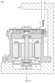
- FIG. 1 is a cross-sectional view showing a cross-sectional configuration of a motor device according to one embodiment.
- FIG. 2 is a perspective view showing a substrate according to the embodiment.
- FIG. 4 is a partial cross-sectional view of the substrate and the bearing holder according to the embodiment.
- 5A to 5C are cross-sectional views showing a process of fixing the substrate in accordance with the embodiment.
- FIG. 1 shows a cross-sectional configuration of a motor device 10.
- the motor device 10 shown in Fig. 1 includes a motor housing 12 and a cover 14.
- a motor mounted on, for example, a steering device of a vehicle and a control device are housed in a packaged state within a space defined by the motor housing 12 and the cover 14.
- the steering device may be, for example, a steer-by-wire type device in which power transmission between the steering wheel and the steered wheels is blocked.
- the motor included in the motor device 10 may be a motor that applies a reaction force to the steering wheel.
- the motor included in the motor device 10 may be a motor that steers the steered wheels.
- the motor 20 is housed in a space defined by the motor housing 12 of the motor device 10.
- the motor housing 12 is made of metal.
- the motor housing 12 may be made of aluminum.
- the motor 20 includes a stator 22, a rotor 24, and a rotating shaft 26.
- the stator 22 of this embodiment has two systems of stator coils that are insulated from each other. This is a redundant design that aims to enable the stator 22 to generate a magnetic field even if an abnormality occurs in either system.
- the rotor 24 includes a rotor core 24a and a permanent magnet 24b provided on the surface of the rotor core 24a.
- the motor 20 is a surface magnet synchronous motor (hereinafter referred to as SPMSM).
- SPMSM surface magnet synchronous motor
- the axial direction of the rotating shaft 26 is the z-axis direction. Therefore, the radial direction of the rotor 24 is a direction perpendicular to the z-axis. In other words, the radial direction of the rotor 24 is expressed by the sum of a vector in the x-axis direction and a vector in the y-axis direction.
- the motor housing 12 has a peripheral wall (side wall 16) that forms the outer periphery, and an end wall that closes one end of the side wall 16.
- the motor housing 12 is open at the other end of the side wall 16. In other words, the motor housing 12 is open in the positive direction of the z axis in FIG. 1.
- the opening of the motor housing 12 is closed by a bearing holder 40.
- the bearing holder 40 is substantially plate-shaped.
- the bearing holder 40 is made of metal. As an example, the bearing holder 40 is made of aluminum.
- a first recess 13 is formed in the center of the end wall of the motor housing 12, penetrating in the z-axis direction.
- a second recess 42 is formed in the center of the bearing holder 40, penetrating in the z-axis direction.
- the first recess 13 and the second recess 42 are formed in a circular shape when viewed from the z-axis direction.
- a first bearing 30 is provided in the first recess 13 formed in the motor housing 12.
- the first bearing 30 is provided between the inner peripheral surface of the first recess 13 and the outer peripheral surface of the rotating shaft 26.
- the first bearing 30 rotatably supports the first end of the rotating shaft 26, which is the end in the negative z-axis direction.
- a second bearing 32 is provided in a second recess 42 formed in the bearing holder 40.
- the second bearing 32 is provided between the inner peripheral surface of the second recess 42 and the outer peripheral surface of the rotating shaft 26.
- the second bearing 32 rotatably supports a second end of the rotating shaft 26, which is the end on the positive z-axis direction side. As a result, the rotating shaft 26 is rotatably supported against the inner wall surface of the motor housing 12 via the first bearing 30 and the second bearing 32.
- the bearing holder 40 has a first surface and a second surface that face opposite to each other in the z-axis direction.
- the first surface faces the stator 22 and the rotor 24 in the z-axis direction.
- the second surface is a control side that faces the substrate 50.
- a drive circuit and a control circuit are mounted on the substrate 50.
- the drive circuit is a circuit that drives the motor 20.
- the drive circuit includes an inverter and the like.
- the control circuit is a circuit that controls the torque of the motor 20 by operating the drive circuit.
- the board 50 is fixed to the motor housing 12 by bolts 60.
- the motor housing 12 has a number of posts 18 located radially inward of the side wall 16 of the motor housing 12.
- the board 50 is fastened to the posts 18 by the bolts 60.
- the posts 18 have threaded holes into which the bolts 60 are inserted.
- FIG. 2 is a diagram of the substrate 50 viewed from the positive direction of the z-axis with the cover 14 removed. 2, the circuit board 50 is fastened to the motor housing 12 by ten bolts 60(a) to 60(j). Note that the letters in parentheses following "bolt 60" are provided to identify the bolts 60.
- the substrate 50 has a first surface facing the bearing holder 40 and a second surface facing the opposite direction to the first surface in the z-axis direction.
- the switching elements Sup, Sun, Svp, Svn, Swp, and Swn that constitute an inverter that drives the stator 22 are mounted on the first surface of the substrate 50.
- the numbers in parentheses after the symbols of the switching elements Sup, Sun, Svp, Svn, Swp, and Swn indicate whether each switching element corresponds to the first system or the second system.
- the switching elements Sup(1), Sun(1), Svp(1), Svn(1), Swp(1), and Swn(1) constitute an inverter that drives the stator coil of the first system.
- switching elements Sup(2), Sun(2), Svp(2), Svn(2), Swp(2), and Swn(2) constitute an inverter that drives the stator coil of the second system.
- the number in parentheses at the end of the symbol will indicate whether the component corresponds to the first system or the second system. If the number in parentheses is omitted, the first system and the second system will be described collectively.
- Filter capacitors 70, 72 are mounted on the second surface of the substrate 50.
- a pre-driver 74 for driving the inverter is also mounted on the second surface of the substrate 50.
- a power supply circuit 76 and a microcomputer 78 are also mounted on the substrate 50.
- the microcomputer 78 is a processing circuit that executes processing to operate the inverter to control the current flowing through the stator 22.
- the power supply circuit 76 is a dedicated integrated circuit that controls the power supply to the microcomputer 78.
- the power supply circuit 76 and the microcomputer 78 are mounted on both the first surface and the second surface of the substrate 50.
- the first system of electronic components and the second system of electronic components are arranged in different regions of the substrate 50. That is, the first system of electronic components and the second system of electronic components are each arranged in two regions of the substrate 50 divided by a plane S that passes through the z axis and is parallel to the z axis. Here, the two regions have approximately equal areas. Furthermore, the electronic components mounted in each of the two regions are symmetrical. Regarding the sensors that detect the rotation angle of the rotor 24, the sensor corresponding to the first system and the sensor corresponding to the second system are arranged overlapping in the z axis direction.
- FIG. 3 shows a cross-sectional view of a portion of the substrate 50 and the bearing holder 40.
- the cross-section shown in FIG. 3 is not along a single plane.
- the cross-section shown in FIG. 3 is a cross-section obtained by conveniently connecting cross-sections of multiple locations of the motor device 10.
- power electronic components that consume a large amount of power such as an inverter
- FIG. 3 shows an example of a configuration in which a switching element Sup, a shunt resistor 80, and a capacitor 70 dissipate heat to the bearing holder 40 via a heat dissipation grease 90.
- the shunt resistor is provided in each leg of the inverter. The detected value of the voltage drop in the shunt resistor indicates the detected value of the current flowing in the corresponding leg.
- the capacitor 70 does not protrude from the first surface of the substrate 50 that faces the bearing holder 40. Therefore, the heat generated by the capacitor 70 is dissipated to the bearing holder 40 via the substrate 50 and the heat dissipation grease 90.
- the amount of protrusion ⁇ 1 of the switching element Sup from the substrate 50 toward the bearing holder 40 is smaller than the amount of protrusion ⁇ 2 of the shunt resistor 80 from the substrate 50 toward the bearing holder 40. Therefore, the distance between the bearing holder 40 and the substrate 50 is smaller in the region where the switching element Sup is provided than in the region where the shunt resistor 80 is provided.
- the capacitor 70 does not protrude toward the bearing holder 40 from the substrate 50. Therefore, the distance between the bearing holder 40 and the substrate 50 is smaller in the region where the capacitor 70 is provided than in the region where the switching element Sup and the shunt resistor 80 are provided.
- This relationship does not only hold for the shunt resistor 80, the switching element Sup, and the capacitor 70.
- This relationship generally holds in the region of the bearing holder 40 that faces the power system electronic components.
- this relationship generally holds when the first electronic component and the second electronic component, which are two electronic components included in the power system electronic components, have different amounts of protrusion toward the bearing holder 40 from the board 50.
- the distance between the portion of the bearing holder 40 that faces the first electronic component and the board 50 is greater than the distance between the portion of the bearing holder 40 that faces the second electronic component, which has a smaller amount of protrusion than the first electronic component, and the board 50.
- the distance between the area of the substrate 50 where the switching element Sup is provided and the bearing holder 40 is the sum of the protrusion amount ⁇ 1 and the thickness of the heat dissipation grease 90.
- the thickness of the heat dissipation grease 90 refers to the length of the heat dissipation grease 90 in the z-axis direction.
- the distance between the area of the substrate 50 where the shunt resistor 80 is provided and the bearing holder 40 is the sum of the protrusion amount ⁇ 2 and the thickness of the heat dissipation grease 90.
- the distance between the area of the substrate 50 where the capacitor 70 is provided and the bearing holder 40 is equal to the thickness of the heat dissipation grease 90.
- the portion of the bearing holder 40 that faces the power electronic components constitutes a heat absorbing portion Pah.
- the heat dissipation grease 90 is not provided on the portion of the microcomputer 78 that protrudes from the substrate 50 toward the bearing holder 40. Therefore, a gap is formed between the microcomputer 78 and the bearing holder 40.
- the microcomputer 78 is provided closer to the bolt 60 than the power system components. As shown in FIG. 2, not only the microcomputer 78 but also the power supply circuit 76 and the pre-driver 74 are provided closer to the bolt 60 than the power system components.
- the microcomputer 78, the power supply circuit 76, the pre-driver 74, etc. are control system electronic components. The control system electronic components consume less power than the power system electronic components.
- FIG. 4 shows the process of fixing the substrate 50 to the motor housing 12. 4, a positioning protrusion 102 of the automatic fastening machine 100 is fitted into the positioning hole Hp of the motor housing 12.
- the positioning protrusion 102 is a protrusion for determining the position of the motor housing 12 when fastening the bolt 60. Then, the automatic fastening machine 100 causes the bolt 60 to penetrate the substrate 50 and be fastened to the support 18.
- a support pillar 18 is provided near the edge of the opening of the motor housing 12.
- the board 50 is screwed to the support pillar 18 without using the bearing holder 40. Therefore, the automatic fastening machine 100 can more smoothly fasten the screws than when the board 50 is fastened to the bearing holder 40 by screws.
- the screw fastening operation by the automatic fastening machine 100 is performed with the motor housing 12 positioned by the positioning protrusions 102.
- the bearing holder 40 is a separate member from the motor housing 12. Therefore, if the board 50 is fastened to the bearing holder 40 with screws, the relative positional relationship between the screw holes of the bearing holder 40 and the automatic fastening machine 100 becomes an issue. However, when the bearing holder 40 is assembled to the motor housing 12, assembly errors occur. Therefore, there is a risk that the screw holes of the bearing holder 40 will deviate from the position assumed by the automatic fastening machine 100.
- the bolts 60 are fastened into the threaded holes in the motor housing 12, so that the threaded holes can be determined with high accuracy at the positions assumed by the automatic fastening machine 100.
- the substrate 50 is in contact with the support 18. This allows the heat of the substrate 50 to flow directly into the motor housing 12.
- the pillars 18 are provided adjacent to the side walls 16 of the motor housing 12. The bases of the pillars 18 are connected to the portions of the side walls 16 that face the pillars 18. This makes it possible to promote the flow of heat that has flowed from the substrate 50 into the pillars 18 into the side walls 16 of the motor housing 12. Therefore, the side walls 16 can be effectively used as heat dissipation members.
- the support pillars 18 and the side walls 16 form a heat transfer path for the control system electronic components such as the microcomputer 78. This allows the heat dissipation path for the control system electronic components to be separated from the heat dissipation path for the power system electronic components.
- control system electronic components are positioned closer to the support pillar 18 than the power system electronic components. This makes it easier to dissipate heat generated by the control system electronic components to the support pillar 18 compared to when the control system electronic components are positioned farther from the support pillar 18 than the power system electronic components.
- the distance between the heat absorption part Pah and the substrate 50 is set according to the amount of protrusion of the power electronic components facing the heat absorption part Pah toward the substrate 50 toward the bearing holder 40. This allows the distance between the power electronic components, which are heat generating bodies, and the bearing holder 40 to be as close as possible. This promotes heat dissipation from the power electronic components to the heat absorption part Pah.
- the heat dissipation grease 90 is provided between the power electronic components and the heat absorbing portion Pah. This can promote heat dissipation from the power electronic components to the heat absorbing portion Pah.
- No heat dissipation grease is provided in the region of the bearing holder 40 where the control system electronic components are projected in the direction along the z-axis. This makes it possible to prevent heat from the bearing holder 40 from flowing into the control system electronic components.
- the pillars 18 are positioned radially outward from the bearing holder 40. This simplifies the shape of the bearing holder 40 compared to when the pillars 18 are inserted into holes that penetrate the bearing holder 40.
- the inverters of the first system and the inverters of the second system are arranged symmetrically with respect to the plane S. This allows the heat generated by each of the inverters of the first system and the inverters of the second system to be dissipated more efficiently than when the inverters of the first system and the inverters of the second system are biased toward one of the two regions divided by the plane S.
- the arrangement of the support columns 18 is not limited to that shown in FIG.
- the number of support columns 18 is not limited to 10. For example, it may be any number equal to or greater than 2. In this case, it is not essential that the number be an even number.
- the support pillar 18 be disposed so as to face the side wall 16 of the motor housing 12.
- the board fixing portion is not limited to the support pillar 18.
- the board fixing portion may be a part of the side wall 16.
- the side wall of the motor housing 12 may be expanded radially inward, and a screw hole for inserting the bolt 60 may be provided in the expanded side wall.
- the difference between the position of the part of the heat absorbing part Pah facing the electronic component and the position of the tip surface (substrate support surface) of the support 18 in the direction along the z axis is the sum of the protrusion amount of the electronic component and the thickness of the heat dissipation grease 90, but this is not limited to the above.
- the difference between the position of the part of the heat absorbing part Pah facing the electronic component and the position of the tip surface of the support 18 in the direction along the z axis may be larger than the sum of the protrusion amount of the electronic component and the thickness of the heat dissipation grease 90.
- a gap may exist between the heat dissipation grease 90 and the substrate 50.
- the z-axis coordinate component of the control side of the bearing holder 40 is larger in the second portion facing the second electronic component with a smaller protrusion amount than in the first portion facing the first electronic component with a larger protrusion amount, but this is not limited to this. For example, they may be equal.
- the heat dissipation member is not limited to the heat dissipation grease 90.
- a heat dissipation sheet or a heat dissipation rubber may be used.
- the motor does not necessarily have to be an SPMSM.
- the motor may be, for example, an interior permanent magnet synchronous motor, a wound field synchronous motor, or a DC motor.
- the motor may also be, for example, an induction motor.
- the stator 22 is provided with redundancy by having two systems of stator coils that make up the stator 22, but this is not limited to the above.
- the stator 22 may be provided with redundancy by having three or more systems of stator coils that make up the stator 22.
- stator coil constituting the stator 22 of the motor may be a single system.
- "Layout for stator coil redundancy" the electronic components of each system are symmetrically arranged in response to the redundancy of the stator 22.
- this is not limiting.
- only some of the components of each system, such as the inverters of each system, may be arranged symmetrically.
Landscapes
- Engineering & Computer Science (AREA)
- Power Engineering (AREA)
- Manufacturing & Machinery (AREA)
- Microelectronics & Electronic Packaging (AREA)
Abstract
Description
図1に、モータ装置10の断面構成を示す。
図1に示すモータ装置10は、モータハウジング12およびカバー14を備える。モータハウジング12およびカバー14によって区画される空間内に、例えば車両の操舵装置に搭載されるモータと、制御装置と、がパッケージ化された状態で収容されている。操舵装置は、たとえばステアリングホイールと転舵輪との間の動力伝達が遮断されたステアバイワイヤ式の装置であってもよい。その場合、モータ装置10が備えるモータは、ステアリングホイールに反力を付与するモータであってもよい。また、モータ装置10が備えるモータは、転舵輪を転舵させるモータであってもよい。
図2に示すように、基板50は、10個のボルト60(a)~60(j)によってモータハウジング12に締結されている。なお、「ボルト60」の後に付与したかっこ内のアルファベットは、ボルト60を識別するために記載した。
一方、マイクロコンピュータ78が基板50に対してベアリングホルダ40に向けて突出している部分には、放熱グリス90が設けられていない。そのため、マイクロコンピュータ78とベアリングホルダ40との間には隙間が形成されている。また、マイクロコンピュータ78は、パワー系部品よりも、ボルト60の近くに設けられている。図2に示すように、マイクロコンピュータ78のみならず、電源回路76およびプリドライバ74についても、パワー系部品よりもボルト60の近くに設けられている。マイクロコンピュータ78、電源回路76およびプリドライバ74等は、制御系電子部品である。制御系電子部品は、パワー系電子部品よりも消費電力が小さい。
図4に示すように、モータハウジング12の位置決め孔Hpには、自動締結機100の位置決め突起102がはめ込まれる。位置決め突起102は、ボルト60の締結に際して、モータハウジング12の位置を定めるための突起である。そして、自動締結機100によって、ボルト60が基板50を貫通して支柱18に締結される。
モータハウジング12の開口縁部付近には、支柱18が設けられている。基板50は、ベアリングホルダ40を介すことなく、支柱18にねじ止めされている。そのため、ベアリングホルダ40に基板50をねじで締結する場合と比較して、自動締結機100によるねじの締結を良好に行うことができる。
なお、上記実施形態は、さらに以下の作用効果を奏する。
(2)モータハウジング12の側壁16に隣接して支柱18を設けた。そして、支柱18の根本が側壁16のうちの支柱18に対向する部分に連結される構成とした。これにより、基板50から支柱18へと流入した熱がモータハウジング12の側壁16に流入することを促進することができる。そのため、側壁16を熱の放熱部材として有効活用できる。
(7)ベアリングホルダ40のうち、制御系電子部品をz軸に沿った方向に投影した領域には、放熱グリスを設けない。これにより、ベアリングホルダ40からの熱が制御系電子部品に流入することを抑制できる。
なお、本実施形態は、以下のように変更して実施することができる。本実施形態および以下の変更例は、技術的に矛盾しない範囲で互いに組み合わせて実施することができる。
・支柱18の配置は、図2に例示したものに限らない。
・支柱18の数は、10個に限らない。たとえば、2個以上の任意の複数であってもよい。その際、偶数であることも必須ではない。
・基板固定部としては、支柱18に限らない。たとえば、基板固定部は、側壁16の一部であってもよい。具体的には、たとえば、モータハウジング12の側壁を径方向内側に拡大して、拡大した側壁にボルト60を挿入するねじ穴を設けてもよい。
・上記実施形態では、z軸に沿った方向において、吸熱部Pahのうちの電子部品に対向する部分の位置と、支柱18の先端面(基板支持面)の位置との差を、電子部品の突出量と放熱グリス90の厚さとの和としたが、これに限らない。たとえば、z軸に沿った方向において、吸熱部Pahのうちの電子部品に対向する部分の位置と、支柱18の先端面の位置との差を、電子部品の突出量と放熱グリス90の厚さとの和よりも大きくしてもよい。換言すれば、放熱グリス90と基板50との間に隙間が存在してもよい。
・放熱部材としては、放熱グリス90に限らない。たとえば、放熱シートであってもよいし、放熱ゴムであってもよい。
・モータが、SPMSMであることは必須ではない。モータは、たとえば、埋込磁石同期電動機であってもよいし、巻き線界磁型同期電動機であってもよいし、直流モータであってもよい。モータは、またたとえば誘導機であってもよい。
「ステータコイルの冗長性に対応するレイアウトについて」
・上記実施形態では、ステータ22の冗長性に対応して、各系統の電子部品を対称的に配置したが、これに限らない。たとえば、各系統のインバータ等、各系統の一部の部品に限って対称性を持たせて配置してもよい。
Claims (9)
- モータ、モータハウジング、ベアリングホルダ、および基板を備え、
前記モータのステータは、前記モータハウジングと前記ベアリングホルダとによって区画される空間に収容され、
前記ベアリングホルダは、前記モータの回転軸を支持しており、
前記ベアリングホルダは、前記回転軸の軸方向において互いに逆向きの第1の面と第2の面とを有し、前記第1の面は前記ステータに対向しており、
前記基板は、前記第2の面に対向して配置されており、
前記基板には、複数の電子部品が実装されており、
前記モータハウジングは、前記基板を固定するための穴が形成された基板固定部を有するモータ装置。 - 前記基板固定部は、前記モータハウジングの側壁の内側に設けられた支柱であり、
前記支柱の根本部分が前記側壁のうち前記支柱に対向する部分に連結されている請求項1記載のモータ装置。 - 前記ベアリングホルダは、複数の前記電子部品のうちの1または複数の所定の電子部品の熱を吸熱するように構成される吸熱部を有し、
前記軸方向における前記吸熱部の位置と前記基板固定部の位置との差は、前記所定の電子部品が前記基板に対して前記ベアリングホルダに向かって前記軸方向に突出する長さ以上である請求項1記載のモータ装置。 - 前記所定の電子部品は、第1電子部品、および第2電子部品を含み、
前記吸熱部は、前記第1電子部品に対向する第1部分と、前記第2電子部品に対向する第2部分と、を含み、
前記第1電子部品が前記基板に対して前記軸方向に突出する長さは、前記第2電子部品が前記基板に対して前記軸方向に突出する長さよりも大きく、
前記第1部分と前記基板との距離は、前記第2部分と前記基板との距離よりも大きい請求項3記載のモータ装置。 - 前記吸熱部と前記所定の電子部品との間には、放熱部材が設けられている請求項3記載のモータ装置。
- 所定の電子部品は、パワー系電子部品であり、
複数の前記電子部品には、前記パワー系電子部品よりも消費電力が小さい制御系電子部品が含まれ、
前記制御系電子部品と前記ベアリングホルダとの間には空間が設けられて且つ、該空間には、前記放熱部材が設けられていない請求項5記載のモータ装置。 - 前記制御系電子部品は、前記パワー系電子部品よりも前記基板固定部に近い位置に配置されている請求項6記載のモータ装置。
- 前記基板固定部は、前記ベアリングホルダよりも前記モータの径方向外側に設けられている請求項1記載のモータ装置。
- 前記モータは、互いに独立した電流の流通経路である第1系統、および第2系統を含み、
複数の前記電子部品は、第1系統スイッチング素子および第2系統スイッチング素子を含み、
前記第1系統スイッチング素子は、前記第1系統の電流を制御するように構成され、
前記第2系統スイッチング素子は、前記第2系統の電流を制御するように構成され、
前記第1系統スイッチング素子は、前記基板の第1領域に設けられ、
前記第2系統スイッチング素子は、前記基板の第2領域に設けられ、
前記第1領域と前記第2領域とは、それぞれ、前記基板が前記所定平面によって分割された2つの領域であり、
前記所定平面は、前記モータの回転軸を通って且つ前記軸方向に平行な平面である請求項1記載のモータ装置。
Priority Applications (4)
| Application Number | Priority Date | Filing Date | Title |
|---|---|---|---|
| EP22969193.6A EP4641894A4 (en) | 2022-12-21 | 2022-12-21 | ENGINE DEVICE |
| PCT/JP2022/047161 WO2024134806A1 (ja) | 2022-12-21 | 2022-12-21 | モータ装置 |
| JP2024565479A JPWO2024134806A1 (ja) | 2022-12-21 | 2022-12-21 | |
| CN202280102616.2A CN120500802A (zh) | 2022-12-21 | 2022-12-21 | 马达装置 |
Applications Claiming Priority (1)
| Application Number | Priority Date | Filing Date | Title |
|---|---|---|---|
| PCT/JP2022/047161 WO2024134806A1 (ja) | 2022-12-21 | 2022-12-21 | モータ装置 |
Publications (1)
| Publication Number | Publication Date |
|---|---|
| WO2024134806A1 true WO2024134806A1 (ja) | 2024-06-27 |
Family
ID=91588209
Family Applications (1)
| Application Number | Title | Priority Date | Filing Date |
|---|---|---|---|
| PCT/JP2022/047161 Ceased WO2024134806A1 (ja) | 2022-12-21 | 2022-12-21 | モータ装置 |
Country Status (4)
| Country | Link |
|---|---|
| EP (1) | EP4641894A4 (ja) |
| JP (1) | JPWO2024134806A1 (ja) |
| CN (1) | CN120500802A (ja) |
| WO (1) | WO2024134806A1 (ja) |
Citations (4)
| Publication number | Priority date | Publication date | Assignee | Title |
|---|---|---|---|---|
| JP2016034204A (ja) * | 2014-07-31 | 2016-03-10 | 株式会社デンソー | 駆動装置、および、これを用いた電動パワーステアリング装置 |
| WO2018062004A1 (ja) * | 2016-09-30 | 2018-04-05 | 日本電産株式会社 | モータ制御装置、モータ、および電動パワーステアリング装置 |
| JP2018170895A (ja) * | 2017-03-30 | 2018-11-01 | 株式会社ジェイテクト | 電子制御装置 |
| JP2021061653A (ja) | 2019-10-03 | 2021-04-15 | 株式会社ジェイテクト | モータ装置 |
Family Cites Families (8)
| Publication number | Priority date | Publication date | Assignee | Title |
|---|---|---|---|---|
| CN107592955B (zh) * | 2015-04-13 | 2019-08-09 | 三菱电机株式会社 | 电动驱动装置 |
| JP6940358B2 (ja) * | 2017-09-29 | 2021-09-29 | 日本電産エレシス株式会社 | 回路基板、モータ駆動装置および電動パワーステアリング装置 |
| JP2020056336A (ja) * | 2018-09-28 | 2020-04-09 | 日本電産トーソク株式会社 | 電動ポンプ装置 |
| DE112019006832T5 (de) * | 2019-03-19 | 2021-12-02 | Hitachi Astemo, Ltd. | Elektronische Steuereinheit und Verfahren zum Montieren der elektronischen Steuereinheit |
| JP7352790B2 (ja) * | 2019-03-29 | 2023-09-29 | パナソニックIpマネジメント株式会社 | 電動工具用モータ及び電動工具 |
| JP7328792B2 (ja) * | 2019-05-17 | 2023-08-17 | 株式会社デンソー | 駆動装置 |
| JP2022068660A (ja) * | 2020-10-22 | 2022-05-10 | 株式会社 神崎高級工機製作所 | 駆動装置 |
| WO2023079670A1 (ja) * | 2021-11-05 | 2023-05-11 | 三菱電機株式会社 | 回転電機 |
-
2022
- 2022-12-21 JP JP2024565479A patent/JPWO2024134806A1/ja active Pending
- 2022-12-21 CN CN202280102616.2A patent/CN120500802A/zh active Pending
- 2022-12-21 WO PCT/JP2022/047161 patent/WO2024134806A1/ja not_active Ceased
- 2022-12-21 EP EP22969193.6A patent/EP4641894A4/en active Pending
Patent Citations (4)
| Publication number | Priority date | Publication date | Assignee | Title |
|---|---|---|---|---|
| JP2016034204A (ja) * | 2014-07-31 | 2016-03-10 | 株式会社デンソー | 駆動装置、および、これを用いた電動パワーステアリング装置 |
| WO2018062004A1 (ja) * | 2016-09-30 | 2018-04-05 | 日本電産株式会社 | モータ制御装置、モータ、および電動パワーステアリング装置 |
| JP2018170895A (ja) * | 2017-03-30 | 2018-11-01 | 株式会社ジェイテクト | 電子制御装置 |
| JP2021061653A (ja) | 2019-10-03 | 2021-04-15 | 株式会社ジェイテクト | モータ装置 |
Non-Patent Citations (1)
| Title |
|---|
| See also references of EP4641894A1 |
Also Published As
| Publication number | Publication date |
|---|---|
| EP4641894A1 (en) | 2025-10-29 |
| EP4641894A4 (en) | 2025-12-31 |
| CN120500802A (zh) | 2025-08-15 |
| JPWO2024134806A1 (ja) | 2024-06-27 |
Similar Documents
| Publication | Publication Date | Title |
|---|---|---|
| US11050325B2 (en) | Motor apparatus | |
| JP6514135B2 (ja) | 電動駆動装置及び電動パワーステアリング装置 | |
| JP5574187B2 (ja) | 駆動装置 | |
| JP6522536B2 (ja) | 電動駆動装置及び電動パワーステアリング装置 | |
| JP6505038B2 (ja) | 電動駆動装置及び電動パワーステアリング装置 | |
| US9537367B2 (en) | Driving device | |
| US10749415B2 (en) | Motor device | |
| JP5287787B2 (ja) | 電動装置 | |
| US8299664B2 (en) | Drive apparatus and semiconductor module | |
| JP6514136B2 (ja) | 電動駆動装置及び電動パワーステアリング装置 | |
| JP2014183615A (ja) | 回転電機 | |
| JP6862570B2 (ja) | 電動パワーステアリング装置 | |
| JP7406546B2 (ja) | モータ | |
| EP3806294B1 (en) | Motor device | |
| JP2016034204A (ja) | 駆動装置、および、これを用いた電動パワーステアリング装置 | |
| JP2017195663A (ja) | モータ装置 | |
| JP6838254B2 (ja) | 電動駆動装置 | |
| JP6870711B2 (ja) | 駆動装置、および、これを用いた電動パワーステアリング装置 | |
| JP6737917B2 (ja) | 電動駆動装置 | |
| EP4641894A1 (en) | Motor device | |
| JP2014075889A (ja) | 位置検出ユニット | |
| JP7827075B2 (ja) | モータユニット | |
| JP2019106885A (ja) | 電動駆動装置 | |
| US20200106329A1 (en) | Motor unit and electric pump device | |
| JP2019106788A (ja) | ロータおよびモータ |
Legal Events
| Date | Code | Title | Description |
|---|---|---|---|
| 121 | Ep: the epo has been informed by wipo that ep was designated in this application |
Ref document number: 22969193 Country of ref document: EP Kind code of ref document: A1 |
|
| WWE | Wipo information: entry into national phase |
Ref document number: 2024565479 Country of ref document: JP |
|
| WWE | Wipo information: entry into national phase |
Ref document number: 202280102616.2 Country of ref document: CN |
|
| WWE | Wipo information: entry into national phase |
Ref document number: 2022969193 Country of ref document: EP |
|
| NENP | Non-entry into the national phase |
Ref country code: DE |
|
| ENP | Entry into the national phase |
Ref document number: 2022969193 Country of ref document: EP Effective date: 20250721 |
|
| ENP | Entry into the national phase |
Ref document number: 2022969193 Country of ref document: EP Effective date: 20250721 |
|
| ENP | Entry into the national phase |
Ref document number: 2022969193 Country of ref document: EP Effective date: 20250721 |
|
| WWP | Wipo information: published in national office |
Ref document number: 202280102616.2 Country of ref document: CN |
|
| WWP | Wipo information: published in national office |
Ref document number: 2022969193 Country of ref document: EP |