WO2024134886A1 - 水電解水素製造システム - Google Patents
水電解水素製造システム Download PDFInfo
- Publication number
- WO2024134886A1 WO2024134886A1 PCT/JP2022/047664 JP2022047664W WO2024134886A1 WO 2024134886 A1 WO2024134886 A1 WO 2024134886A1 JP 2022047664 W JP2022047664 W JP 2022047664W WO 2024134886 A1 WO2024134886 A1 WO 2024134886A1
- Authority
- WO
- WIPO (PCT)
- Prior art keywords
- water
- water electrolysis
- production system
- electrolysis
- stack
- Prior art date
- Legal status (The legal status is an assumption and is not a legal conclusion. Google has not performed a legal analysis and makes no representation as to the accuracy of the status listed.)
- Ceased
Links
Images


Classifications
-
- C—CHEMISTRY; METALLURGY
- C25—ELECTROLYTIC OR ELECTROPHORETIC PROCESSES; APPARATUS THEREFOR
- C25B—ELECTROLYTIC OR ELECTROPHORETIC PROCESSES FOR THE PRODUCTION OF COMPOUNDS OR NON-METALS; APPARATUS THEREFOR
- C25B1/00—Electrolytic production of inorganic compounds or non-metals
- C25B1/01—Products
- C25B1/02—Hydrogen or oxygen
- C25B1/04—Hydrogen or oxygen by electrolysis of water
-
- C—CHEMISTRY; METALLURGY
- C25—ELECTROLYTIC OR ELECTROPHORETIC PROCESSES; APPARATUS THEREFOR
- C25B—ELECTROLYTIC OR ELECTROPHORETIC PROCESSES FOR THE PRODUCTION OF COMPOUNDS OR NON-METALS; APPARATUS THEREFOR
- C25B15/00—Operating or servicing cells
- C25B15/08—Supplying or removing reactants or electrolytes; Regeneration of electrolytes
-
- C—CHEMISTRY; METALLURGY
- C25—ELECTROLYTIC OR ELECTROPHORETIC PROCESSES; APPARATUS THEREFOR
- C25B—ELECTROLYTIC OR ELECTROPHORETIC PROCESSES FOR THE PRODUCTION OF COMPOUNDS OR NON-METALS; APPARATUS THEREFOR
- C25B9/00—Cells or assemblies of cells; Constructional parts of cells; Assemblies of constructional parts, e.g. electrode-diaphragm assemblies; Process-related cell features
- C25B9/60—Constructional parts of cells
- C25B9/65—Means for supplying current; Electrode connections; Electric inter-cell connections
-
- C—CHEMISTRY; METALLURGY
- C25—ELECTROLYTIC OR ELECTROPHORETIC PROCESSES; APPARATUS THEREFOR
- C25B—ELECTROLYTIC OR ELECTROPHORETIC PROCESSES FOR THE PRODUCTION OF COMPOUNDS OR NON-METALS; APPARATUS THEREFOR
- C25B9/00—Cells or assemblies of cells; Constructional parts of cells; Assemblies of constructional parts, e.g. electrode-diaphragm assemblies; Process-related cell features
- C25B9/70—Assemblies comprising two or more cells
-
- C—CHEMISTRY; METALLURGY
- C25—ELECTROLYTIC OR ELECTROPHORETIC PROCESSES; APPARATUS THEREFOR
- C25B—ELECTROLYTIC OR ELECTROPHORETIC PROCESSES FOR THE PRODUCTION OF COMPOUNDS OR NON-METALS; APPARATUS THEREFOR
- C25B9/00—Cells or assemblies of cells; Constructional parts of cells; Assemblies of constructional parts, e.g. electrode-diaphragm assemblies; Process-related cell features
- C25B9/70—Assemblies comprising two or more cells
- C25B9/73—Assemblies comprising two or more cells of the filter-press type
- C25B9/77—Assemblies comprising two or more cells of the filter-press type having diaphragms
Definitions
- the present invention relates to the structure of a water electrolysis hydrogen production system, and in particular to technology that is effective when applied to a large-scale water electrolysis hydrogen production system that is composed of multiple water electrolysis stacks connected in series.
- Patent Document 1 discloses "a high-pressure container-type water electrolysis hydrogen generation device that has a simple configuration, is easy to assemble, and is capable of generating large amounts of hydrogen.”
- Patent Document 1 describes a configuration in which multiple water electrolysis stacks (water electrolytic cells in Patent Document 1) are each connected to an independent power supply, and a configuration in which the water electrolysis stacks are connected in series and then connected to a single power supply.
- the configuration in which the water electrolysis stacks are connected in series and then connected to a single power supply results in a simpler power supply configuration.
- Patent Document 2 also discloses a "water electrolysis system that has a simple and compact configuration, does not waste hydrogen dissolved in high-pressure water, and can achieve high efficiency throughout the system.”
- Patent Document 2 above describes the internal structure of the water electrolysis stack (the electrolysis stack in Patent Document 2), and the electrolysis section where the water electrolysis reaction actually occurs in the water electrolysis stack (the section consisting of terminal sections 38a, 38b and the stacked section of unit cells 30 in Patent Document 2) is electrically insulated from the other sections by insulating sections (insulating plates 34a, 34b), which are provided inside the water electrolysis stack. Note that the electrolysis section is generally electrically grounded from the standpoint of durability and reliability of the entire device.
- the power supply configuration can be made small and simple by electrically connecting the multiple water electrolysis stacks in series as in Patent Document 1 above.
- the electrolytic section is insulated from the other sections.
- the other sections are generally electrically grounded, so they are at a uniform electrical potential.
- the greater the number of water electrolysis stacks the greater the maximum potential difference (maximum voltage) between the insulated electrolytic parts within the water electrolysis stack and the parts other than the electrolytic parts.
- the internal insulating parts do not have sufficient insulation performance to ensure insulation against the voltage generated by multiple water electrolysis stacks connected in series.
- the object of the present invention is to provide a water electrolysis hydrogen production system that is configured by connecting multiple water electrolysis stacks in series and that can ensure sufficient insulation performance for each water electrolysis stack.
- the present invention provides a water electrolysis hydrogen production system having multiple water electrolysis devices, the water electrolysis devices having a water electrolysis stack that generates hydrogen and oxygen by electrolysis of water, a water supply unit that supplies water to the water electrolysis stack, a water intake unit that takes in water from the outside to the water supply unit, a hydrogen release unit that releases hydrogen generated in the water electrolysis stack to the outside, and an oxygen release unit that releases oxygen generated in the water electrolysis stack to the outside, the water electrolysis stacks of the multiple water electrolysis devices being electrically connected to each other in series, and an insulating member being disposed at the connection between the outside of the device and piping that supplies or releases fluids, including at least the water intake unit, the hydrogen release unit, and the oxygen release unit of the multiple water electrolysis devices.
- the present invention also provides a water electrolysis hydrogen production system having multiple water electrolysis devices, each of which has a water electrolysis stack that generates hydrogen and oxygen by electrolysis of water, a water supply unit that supplies water to the water electrolysis stack, a water intake unit that takes in water from the outside to the water supply unit, a hydrogen release unit that releases hydrogen generated in the water electrolysis stack to the outside, and an oxygen release unit that releases oxygen generated in the water electrolysis stack to the outside, and each of the water electrolysis stacks of the multiple water electrolysis devices is electrically connected in series with each other, and insulating members are arranged in piping between at least one of the water intake unit, the hydrogen release unit, and the oxygen release unit and the water electrolysis stack.
- the present invention makes it possible to realize a water electrolysis hydrogen production system that is configured by connecting multiple water electrolysis stacks in series, and that can ensure sufficient insulation performance for each water electrolysis stack.
- FIG. 1 is a diagram showing a schematic configuration of a water electrolysis hydrogen production system according to a first embodiment of the present invention.
- FIG. FIG. 2 is a diagram showing the structure of the water electrolysis stack of FIG. 1 . 1.
- FIG. 4 is a diagram showing a modified example of an insulating member in the water intake section of FIG.
- FIG. 1 is a diagram showing a schematic configuration of a water electrolysis hydrogen production system according to a second embodiment of the present invention.
- FIG. 11 is a diagram showing a schematic configuration of a water electrolysis hydrogen production system according to a third embodiment of the present invention.
- FIG. 6 is a diagram showing the structure of the water electrolysis stack of FIG. 5 .
- FIG. 11 is a diagram showing a schematic configuration of a water electrolysis hydrogen production system according to a fourth embodiment of the present invention.
- FIG. 11 is a diagram showing a schematic configuration of a water electrolysis hydrogen production system according to a fifth embodiment of the present invention.
- FIG. 13 is a diagram showing a schematic configuration of a water electrolysis hydrogen production system according to a sixth embodiment of the present invention.
- FIG. 10 is a diagram showing a modified example of the water electrolysis hydrogen production system shown in FIG.
- FIG. 13 is a diagram showing a schematic configuration of a water electrolysis hydrogen production system according to a seventh embodiment of the present invention.
- FIG. 1 is a diagram showing a schematic configuration of a conventional multi-serial water electrolysis hydrogen production system.
- Fig. 12 shows the schematic configuration of a conventional multi-series water electrolysis hydrogen production system.
- Fig. 12 shows an example in which 10 water electrolysis stacks 3 are connected in series.
- a conventional multi-serial water electrolysis hydrogen production system is configured by electrically connecting water electrolysis stacks 3 in series.
- a power supply 12 is connected to both ends of the 10 water electrolysis stacks 3 connected in series, and a voltage for the 10 water electrolysis stacks is applied.
- the voltage for one water electrolysis stack is 0.5 kV
- a total voltage of 5.0 kV (0.5 kV/stack x 10 stacks) is applied to all 10 water electrolysis stacks 3.
- the potential on the positive electrode (+) side of the first water electrolysis stack 3 is 2.5 kV
- the potential on the negative electrode (-) side is 2.0 kV.
- the potential on the positive electrode (+) side of the tenth water electrolysis stack 3 is -2.0 kV, and the potential on the negative electrode (-) side is -2.5 kV. Current flows from the first water electrolysis stack 3 to the tenth water electrolysis stack 3.
- Water ( H2O ) taken in from the outside via the water intake unit 4 is sent to the water supply unit 5 of the water electrolysis stack 3 by an electric motor 10 such as a water pump, and is taken into the water electrolysis stack 3 via the water supply unit 5.
- the water ( H2O ) taken into the water electrolysis stack 3 is decomposed into hydrogen ( H2 ) and oxygen ( O2 ) by a water electrolysis reaction caused by a voltage (0.5 kV) for one water electrolysis stack applied to the water electrolysis stack 3, and these are released to the outside via the hydrogen release unit 6 and the oxygen release unit 7, respectively.
- oxygen ( O2 ) generated inside the water electrolysis stack 3 is released from the water electrolysis stack 3 as a mixture ( O2 , H2O ) with water ( H2O ) that did not contribute to the reaction.
- the oxygen ( O2 ) is released to the outside from the oxygen release section 7, and the water ( H2O ) is supplied back into the water electrolysis stack 3 via the water supply section 5.
- the water electrolysis stack 3 has insulating sections 8 arranged at the locations where pipes that supply or release fluids, such as the water supply section 5, hydrogen release section 6, and oxygen release section 7, are connected, and is insulated from the outside except for the electrode section to which the power source 12 is connected. In addition, all parts except the electrode section to which the power source 12 is connected are grounded (0 kV).
- the first water electrolysis stack 3 generates a maximum potential difference of 2.5 kV relative to the ground potential (0 kV), and the tenth water electrolysis stack 3 generates a maximum potential difference of -2.5 kV relative to the ground potential (0 kV).
- the internal insulating part 8 has insulation performance that can normally withstand a self-generated voltage of 0.5 kV.
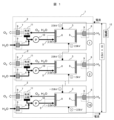
- FIG. 1 is a diagram showing the schematic configuration of a water electrolysis hydrogen production system 1 according to this embodiment.
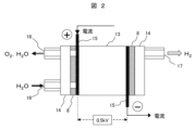
- FIG. 2 is a diagram showing the structure of the water electrolysis stack 3 shown in FIG. 1.
- FIG. 3 is a diagram showing a modified example of the insulating member 9 in the water intake section 4 shown in FIG. 1.
- the water electrolysis hydrogen production system 1 of this embodiment is configured with ten water electrolysis devices 2 each having a water electrolysis stack 3.
- the water electrolysis stacks 3 of each water electrolysis device 2 are electrically connected in series with each other, and a power source 12 is connected to the anode (positive electrode) side of the first water electrolysis stack 3 and the cathode (negative electrode) side of the tenth water electrolysis stack 3.
- the water electrolysis device 2 mainly comprises a water supply unit 5 that supplies water (H 2 O) to the water electrolysis stack 3, a water intake unit 4 that takes in water (H 2 O) from the outside to the water supply unit 5, a hydrogen release unit 6 that releases hydrogen (H 2 ) generated in the water electrolysis stack 3 to the outside, an oxygen release unit 7 that releases oxygen (O 2 ) generated in the water electrolysis stack 3 to the outside, and a gas-liquid separator 11 that separates a mixture (O 2 , H 2 O) of oxygen (O 2 ) and water (H 2 O) into oxygen (O 2 ) and water ( H 2 O).
- the water electrolysis device 2 has an insulating member 9 disposed at the connection between the piping that supplies or releases fluid, including the water intake section 4, hydrogen release section 6, and oxygen release section 7, and the outside of the device.
- the water electrolysis stack 3 is held by clamping the electrolysis section 13, the power supply plate 15, and the insulating section 8 together with end plates 14, and further includes a water supply port 16, a mixing outlet 18, and a hydrogen outlet 17.
- the electrolysis section 13 of the water electrolysis stack 3 contains a membrane electrode assembly (MEA) consisting of a solid polymer membrane and an anode (positive electrode) and a cathode (negative electrode) on either side of the membrane (negative electrode) (both not shown), and water (H 2 O) is supplied to the anode (positive electrode) through a water supply port 16, and a current is passed from one (left side in FIG. 2 ) of a pair of power supply plates 15 to the other (right side in FIG. 2 ) to cause a water electrolysis reaction in the electrolysis section 13.
- MEA membrane electrode assembly
- oxygen (O 2 ) generated at the anode (positive electrode) and water (H 2 O) that did not contribute to the reaction are discharged from a mixture discharge port 18 to the outside of the water electrolysis stack 3, and hydrogen (H 2 ) generated at the cathode (negative electrode) is discharged from a hydrogen discharge port 17 to the outside of the water electrolysis stack 3.
- the mixture of oxygen ( O2 ) and water ( H2O ) discharged from the mixed discharge port 18 is separated into oxygen ( O2 ) and water ( H2O ) in the gas-liquid separator 11, and then the oxygen ( O2 ) is released from the oxygen release section 7 to the outside of the water electrolysis device 2, and the water ( H2O ) is again supplied from the water supply section 5 to the water electrolysis stack 3 through the water supply port 16.
- an amount of water ( H2O ) equivalent to the amount consumed in the water electrolysis reaction is taken in from the water intake section 4 and supplied from the water supply section 5 to the water electrolysis stack 3 through the water supply port 16.
- the water ( H2O ) supplied from the water intake section 4 is pure water or ultrapure water with a resistivity of 1 to 10 M ⁇ cm or more, and within the water electrolysis hydrogen production system 1, the resistivity of the water inside the system is maintained by flowing it through an ion exchange resin (not shown).
- the pair of power supply plates 15 and the electrolysis section 13 of the water electrolysis stack 3 are electrically insulated from the end plates 14 and other components such as piping by the insulating section 8.
- the water electrolysis stack 3 generates a voltage of 0.5 kV between a pair of power supply plates 15 during the water electrolysis reaction, so the difference between the maximum and minimum potentials of the 10 water electrolysis stacks 3 connected in series is 5 kV.
- all insulating members 9 can maintain sufficient insulation between the inside and outside of the water electrolysis device 2 even when a voltage of 5 kV, which is the difference between the maximum and minimum potentials of the water electrolysis stack 3, is applied.
- All of the components inside the water electrolysis device 2, except for the power supply unit, are electrically insulated from the outside by insulating members 9 and are weakly electrically connected to the water electrolysis stack 3 via water ( H2O ). Therefore, inside each water electrolysis device 2, the components and the electrolysis unit 13 in the water electrolysis stack 3 have approximately the same potential.
- the potential on the anode (positive electrode) side of the water electrolysis stack 3 inside the first water electrolysis device 2 is 2.5 kV, but the parts connected to the left side of the water electrolysis stack 3, such as the water supply unit 5, also have a potential of approximately 2.5 kV, and the parts connected to the right side of the water electrolysis stack 3 have a potential of 2.0 kV.
- the water intake section 4 is composed of a water intake tank 19 with an air layer inside and an insulating member 20, and the amount of water taken from the outside is controlled so that the water level in the water intake tank 19 is below the insulating member 20, a situation in which electrical connection is made via water ( H2O ) can be avoided.
- FIG. 4 is a diagram showing the schematic configuration of the water electrolysis hydrogen production system 1 according to the second embodiment.
- the water electrolysis hydrogen production system 1 of this embodiment differs from Example 1 (FIG. 1) in that, instead of the insulating member 9 disposed inside the water electrolysis device 2, the housings of all the water electrolysis devices 2 are insulated housings 21. The rest of the configuration is the same as that of Example 1 (FIG. 1).
- the housings of all water electrolysis devices 2 are constructed from insulating materials, and sufficient insulation can be maintained between the inside and outside of the water electrolysis device 2 even when a voltage of 5 kV, which is the difference between the maximum and minimum potentials of the water electrolysis stack 3, is applied.
- All of the components inside the water electrolysis device 2 are electrically insulated from the outside by the insulating casing 21 of the water electrolysis device 2, and are weakly electrically connected to the water electrolysis stack 3 via water ( H2O ). Therefore, inside each water electrolysis device 2, the components and the electrolysis unit 13 in the water electrolysis stack 3 have approximately the same potential.
- FIG. 5 is a diagram showing the schematic configuration of the water electrolysis hydrogen production system 1 of this embodiment.
- FIG. 6 is a diagram showing the structure of the water electrolysis stack 3 of FIG. 5.
- the water electrolysis hydrogen production system 1 of this embodiment differs from that of Example 1 (FIG. 1) in that, in addition to the configuration of Example 1 (FIG. 1), the water electrolysis stack 3 and the water supply unit 5 are electrically connected via wiring 22, etc.
- the rest of the configuration is the same as that of Example 1 (FIG. 1).
- the water electrolysis stack 3 and the water supply unit 5 are electrically connected inside all water electrolysis devices 2.
- FIG. 6 shows a specific connection between the water electrolysis stack 3 and the water supply unit 5.
- the water electrolysis stack 3 side has an anode (positive electrode) side power supply plate 15, and the water supply unit 5 side has a piping (water supply port 16) that is closest to the connection with the water electrolysis stack 3, which is electrically connected to each other.
- both ends of the insulating section 8 inside the water electrolysis stack 3 are at approximately the same potential.
- connection part on the water electrolysis stack 3 side if it is either the pair of power supply plates 15 or the electrolysis part 13, falls well within the design range of the insulating part 8 and similar performance can be obtained, so it does not go beyond the scope of this invention.
- the water intake unit 5 may be electrically connected to the power supply plate 15 or the electrolysis unit 13.
- FIG. 7 is a diagram showing the schematic configuration of the water electrolysis hydrogen production system 1 according to the fourth embodiment.
- the water electrolysis hydrogen production system 1 of this embodiment differs from that of Example 1 (FIG. 1) in that, in addition to the configuration of Example 1 (FIG. 1), it further includes a potential setting unit 23 in which voltage sources that generate a voltage equivalent to that of each water electrolysis stack 3 are connected in series, the number of which is one less than the number of water electrolysis stacks 3.
- the rest of the configuration is the same as that of Example 1 (FIG. 1).
- the potential setting unit 23 has voltage sources that generate a voltage equal to the water electrolysis stack 3 provided in each water electrolysis device 2, the number of which is one less than the number of water electrolysis devices 2 (water electrolysis stacks 3). In the example of Figure 7, ten water electrolysis stacks 3 are connected in series, and the potential setting unit 23 is composed of nine voltage sources that generate a voltage of 0.5 kV. Each voltage source of the potential setting unit 23 is electrically connected to the water supply unit 5 of each water electrolysis device 2.
- the potential setting unit 23 can also be configured with one voltage source and multiple (e.g., nine) resistors, and since the same performance can be obtained with similar circuit modifications, this does not go beyond the scope of the present invention.
- FIG. 8 is a diagram showing the schematic configuration of the water electrolysis hydrogen production system 1 according to the fifth embodiment.
- the water electrolysis hydrogen production system 1 of this embodiment differs from that of Example 1 (FIG. 1) in that, in addition to the configuration of Example 1 (FIG. 1), it further includes an auxiliary power supply unit 24 that supplies power to the electric motor (water pump) 10, separate from the power supply 12.
- the rest of the configuration is the same as that of Example 1 (FIG. 1).
- the water electrolysis device 2 is equipped with an electric motor 10 such as a water pump, and is often driven by AC200V or AC100V.
- the housing of the motor 10 is connected to components inside the water electrolysis device 2, such as the water supply unit 5, so it is at approximately the same potential as the water electrolysis stack 3 within each water electrolysis device 2. Therefore, if power is supplied directly from an external power source to the motor 10, a large potential difference will occur between the external power source and the housing of the motor 10.
- an electrically isolated power source such as a transformer 25 is connected to the electric motor 10 of the water pump, etc.
- each transformer 25 (the AC power supply side in Fig. 8) is applied with 0.5 kV (the same voltage as the water electrolysis stack 3), and the secondary coil (the water electrolysis device side in Fig. 8) is configured to generate AC200V or AC100V (the power supply voltage for the auxiliary equipment).
- each auxiliary device such as the electric motor 10
- the power supply the durability and reliability of each auxiliary device can be maintained.
- FIG. 9 is a diagram showing the general configuration of the water electrolysis hydrogen production system 1 according to the sixth embodiment.
- Fig. 10 is a diagram showing a modified example of the water electrolysis hydrogen production system 1 shown in Fig. 9.
- the water electrolysis hydrogen production system 1 of this embodiment differs from Example 1 (FIG. 1) in that the insulating members 9 are arranged on the piping between the water intake section 4, hydrogen release section 6, oxygen release section 7, and the water electrolysis stack 3, instead of being arranged on the connections of the piping that supplies or releases fluid to the outside of the device.
- the rest of the configuration is the same as that of Example 1 (FIG. 1).
- the insulating member 9 may be disposed near the water electrolysis stack 3, as shown in FIG. 9.
- a separate insulating member 9 may be disposed on the piping between the water intake section 4, the hydrogen release section 6, the oxygen release section 7, and the water electrolysis stack 3. This can further improve the insulation performance of the water electrolysis stack 3.
- FIG. 11 is a diagram showing the schematic configuration of the water electrolysis hydrogen production system 1 according to the seventh embodiment.
- the water electrolysis hydrogen production system 1 of this embodiment differs from that of Example 6 (FIG. 9) in that, in addition to the configuration of Example 6 (FIG. 9), the water electrolysis stack 3 and the water supply unit 5 are electrically connected via wiring 22, etc. The rest of the configuration is the same as that of Example 6 (FIG. 9).
- the water electrolysis stack 3 and the water supply unit 5 are electrically connected inside all water electrolysis devices 2.
- Example 3 The specific configuration of the connections between the water electrolysis stack 3 and the water intake section 4, water supply section 5, hydrogen release section 6, and oxygen release section 7 is the same as in Example 3 ( Figure 6).
- the power supply plate 15 or electrolysis section 13 of the water electrolysis stack 3 is electrically connected to the water supply section 5.
- both ends of the insulating section 8 inside the water electrolysis stack 3 are at approximately the same potential.
- the water electrolysis stack 3 may be electrically connected to the insulating member 9 side of any of the water supply section 5, the hydrogen release section 6, and the oxygen release section 7.
- the present invention is not limited to the above-mentioned embodiments, but includes various modified examples.
- the above-mentioned embodiments have been described in detail to clearly explain the present invention, and are not necessarily limited to those having all of the configurations described.
- it is possible to replace part of the configuration of one embodiment with the configuration of another embodiment and it is also possible to add the configuration of another embodiment to the configuration of one embodiment.
- 1...water electrolysis hydrogen production system 2...water electrolysis device, 3...water electrolysis stack, 4...water intake section, 5...water supply section, 6...hydrogen release section, 7...oxygen release section, 8...insulating section (of water electrolysis stack), 9, 20...insulating member, 10...motor (water pump), 11...gas-liquid separator, 12...power source, 13...electrolysis section, 14...end plate, 15...power supply plate, 16...water supply port, 17...hydrogen exhaust port, 18...mixing exhaust port, 19...water intake tank, 21...insulating housing, 22...wiring, 23...potential setting section, 24...auxiliary power supply section, 25...transformer.
Landscapes
- Chemical & Material Sciences (AREA)
- Engineering & Computer Science (AREA)
- Chemical Kinetics & Catalysis (AREA)
- Electrochemistry (AREA)
- Materials Engineering (AREA)
- Metallurgy (AREA)
- Organic Chemistry (AREA)
- Inorganic Chemistry (AREA)
- Electrolytic Production Of Non-Metals, Compounds, Apparatuses Therefor (AREA)
Abstract
Description
Claims (11)
- 水電解装置を複数備えた水電解水素製造システムであって、
前記水電解装置は、水の電気分解によって水素と酸素とを発生する水電解スタックと、
前記水電解スタックに水を供給する水供給部と、
前記水供給部に外部から水を取り入れる取水部と、
前記水電解スタックで発生した水素を外部へ放出する水素放出部と、
前記水電解スタックで発生した酸素を外部へ放出する酸素放出部と、を有し、
前記複数の水電解装置の各水電解スタックは互いに電気的に直列に接続されており、
前記複数の水電解装置の少なくとも前記取水部、前記水素放出部、前記酸素放出部を含む、流体を供給または放出する配管類の装置外部との接続部に絶縁部材が配置されていることを特徴とする水電解水素製造システム。 - 請求項1に記載の水電解水素製造システムであって、
前記取水部と前記装置外部との接続部に、内部に空気層を有する取水槽が配置されていることを特徴とする水電解水素製造システム。 - 請求項1に記載の水電解水素製造システムであって、
前記絶縁部材は、前記水電解装置の絶縁筐体であることを特徴とする水電解水素製造システム。 - 請求項1に記載の水電解水素製造システムであって、
前記水電解スタックは、外部より電流を供給する給電板と、
水電解反応を行う電解部と、を有し、
前記水供給部と前記取水部と前記水素放出部と前記酸素放出部の少なくとも1つと、前記給電板または前記電解部とが電気的に接続されていることを特徴とする水電解水素製造システム。 - 請求項1に記載の水電解水素製造システムであって、
前記水供給部と前記取水部と前記水素放出部と前記酸素放出部が、前記水電解スタックの一部と略等電位であることを特徴とする水電解水素製造システム。 - 請求項1に記載の水電解水素製造システムであって、
前記複数の水電解装置の各水電解スタックと同等の電圧を発生させる電圧源を前記水電解スタックの数より1つ少ない数だけ直列接続した電位設定部をさらに備え、
前記水供給部と前記取水部と前記水素放出部と前記酸素放出部の少なくとも1つと、前記電圧源とが電気的に接続されていることを特徴とする水電解水素製造システム。 - 請求項1に記載の水電解水素製造システムであって、
前記水電解装置は、1つ以上の電動機を有し、
前記電動機へ電力を供給する電源は、前記水電解スタックへ電力を供給する電源からトランスを介して絶縁されていることを特徴とする水電解水素製造システム。 - 請求項1に記載の水電解水素製造システムであって、
前記取水部、前記水素放出部、前記酸素放出部の少なくとも1つと、前記水電解スタックとの間の配管類に、前記絶縁部材とは異なる別の絶縁部材が配置されていることを特徴とする水電解水素製造システム。 - 水電解装置を複数備えた水電解水素製造システムであって、
前記水電解装置は、水の電気分解によって水素と酸素とを発生する水電解スタックと、
前記水電解スタックに水を供給する水供給部と、
前記水供給部に外部から水を取り入れる取水部と、
前記水電解スタックで発生した水素を外部へ放出する水素放出部と、
前記水電解スタックで発生した酸素を外部へ放出する酸素放出部と、を有し、
前記複数の水電解装置の各水電解スタックは互いに電気的に直列に接続されており、
前記取水部、前記水素放出部、前記酸素放出部の少なくとも1つと、前記水電解スタックとの間の配管類に、絶縁部材が配置されていることを特徴とする水電解水素製造システム。 - 請求項9に記載の水電解水素製造システムであって、
前記水電解スタックは、外部より電流を供給する給電板と、
水電解反応を行う電解部と、を有し、
前記水供給部と前記取水部と前記水素放出部と前記酸素放出部の少なくとも1つと、前記給電板または前記電解部とが電気的に接続されていることを特徴とする水電解水素製造システム。 - 請求項9に記載の水電解水素製造システムであって、
前記水供給部と前記取水部と前記水素放出部と前記酸素放出部が、前記水電解スタックの一部と略等電位であることを特徴とする水電解水素製造システム。
Priority Applications (2)
| Application Number | Priority Date | Filing Date | Title |
|---|---|---|---|
| PCT/JP2022/047664 WO2024134886A1 (ja) | 2022-12-23 | 2022-12-23 | 水電解水素製造システム |
| EP22969269.4A EP4640922A1 (en) | 2022-12-23 | 2022-12-23 | Water electrolysis hydrogen production system |
Applications Claiming Priority (1)
| Application Number | Priority Date | Filing Date | Title |
|---|---|---|---|
| PCT/JP2022/047664 WO2024134886A1 (ja) | 2022-12-23 | 2022-12-23 | 水電解水素製造システム |
Publications (1)
| Publication Number | Publication Date |
|---|---|
| WO2024134886A1 true WO2024134886A1 (ja) | 2024-06-27 |
Family
ID=91587913
Family Applications (1)
| Application Number | Title | Priority Date | Filing Date |
|---|---|---|---|
| PCT/JP2022/047664 Ceased WO2024134886A1 (ja) | 2022-12-23 | 2022-12-23 | 水電解水素製造システム |
Country Status (2)
| Country | Link |
|---|---|
| EP (1) | EP4640922A1 (ja) |
| WO (1) | WO2024134886A1 (ja) |
Cited By (1)
| Publication number | Priority date | Publication date | Assignee | Title |
|---|---|---|---|---|
| WO2026058474A1 (ja) * | 2024-09-11 | 2026-03-19 | 株式会社日立製作所 | 水電解システム及び水電解システムの制御方法 |
Citations (3)
| Publication number | Priority date | Publication date | Assignee | Title |
|---|---|---|---|---|
| JPH09504053A (ja) * | 1993-09-06 | 1997-04-22 | ハイドロジェン・テクノロジー・リミテッド | 電解システムの改良 |
| JP2000243415A (ja) * | 1999-02-23 | 2000-09-08 | Sumitomo Electric Ind Ltd | 電解液循環型電池の電解液循環装置 |
| JP2009087863A (ja) * | 2007-10-02 | 2009-04-23 | Mitsubishi Materials Corp | 燃料電池 |
Family Cites Families (2)
| Publication number | Priority date | Publication date | Assignee | Title |
|---|---|---|---|---|
| JP4635567B2 (ja) | 2004-11-04 | 2011-02-23 | 日立造船株式会社 | 水電解水素発生装置における容器収納型水電解装置 |
| JP2013053321A (ja) | 2011-09-01 | 2013-03-21 | Honda Motor Co Ltd | 水電解システム |
-
2022
- 2022-12-23 EP EP22969269.4A patent/EP4640922A1/en active Pending
- 2022-12-23 WO PCT/JP2022/047664 patent/WO2024134886A1/ja not_active Ceased
Patent Citations (3)
| Publication number | Priority date | Publication date | Assignee | Title |
|---|---|---|---|---|
| JPH09504053A (ja) * | 1993-09-06 | 1997-04-22 | ハイドロジェン・テクノロジー・リミテッド | 電解システムの改良 |
| JP2000243415A (ja) * | 1999-02-23 | 2000-09-08 | Sumitomo Electric Ind Ltd | 電解液循環型電池の電解液循環装置 |
| JP2009087863A (ja) * | 2007-10-02 | 2009-04-23 | Mitsubishi Materials Corp | 燃料電池 |
Non-Patent Citations (1)
| Title |
|---|
| See also references of EP4640922A1 * |
Cited By (1)
| Publication number | Priority date | Publication date | Assignee | Title |
|---|---|---|---|---|
| WO2026058474A1 (ja) * | 2024-09-11 | 2026-03-19 | 株式会社日立製作所 | 水電解システム及び水電解システムの制御方法 |
Also Published As
| Publication number | Publication date |
|---|---|
| EP4640922A1 (en) | 2025-10-29 |
Similar Documents
| Publication | Publication Date | Title |
|---|---|---|
| US7132189B2 (en) | Fuel cell stack with bypass | |
| KR0123727B1 (ko) | 연료전지의 적층체 | |
| JPH06203862A (ja) | 燃料電池設備の水及び不活性ガス排出方法と装置 | |
| US20070231669A1 (en) | Design of fuel cell and electrolyzer for small volume, low cost and high efficiency | |
| KR102861217B1 (ko) | 고전압 연료 전지 스택 | |
| US7169496B2 (en) | Fuel Cell | |
| US7422814B2 (en) | Fuel cell system | |
| US20060024561A1 (en) | Fuel cell stack | |
| JP2003282125A (ja) | セル分割型燃料電池 | |
| KR101736505B1 (ko) | 슬러리 순환형 아연/공기전지 단위셀용 연료극 | |
| JP4852157B2 (ja) | 水電解装置 | |
| KR100612529B1 (ko) | 연료전지 발전장치 | |
| WO2024134886A1 (ja) | 水電解水素製造システム | |
| US11342575B2 (en) | Fuel cell stack | |
| US7090941B2 (en) | Fuel cell stack and a method of supplying reactant gases to the fuel cell stack | |
| JP2009224194A (ja) | 燃料電池スタック | |
| JP4025282B2 (ja) | 固体高分子型燃料電池 | |
| US20040038103A1 (en) | Solid polymer electrolyte fuel cell assembly | |
| CN219342319U (zh) | 一种叠层臭氧水发生器 | |
| US20090023024A1 (en) | Fuel cell stack | |
| JP2005100807A (ja) | 燃料電池スタック及び燃料電池セル | |
| JP5095715B2 (ja) | 水電解装置 | |
| CN110431699B (zh) | 新型模块化电化学电池单元和堆叠设计 | |
| JP2007234315A (ja) | 燃料電池 | |
| JPH05325993A (ja) | 燃料電池 |
Legal Events
| Date | Code | Title | Description |
|---|---|---|---|
| 121 | Ep: the epo has been informed by wipo that ep was designated in this application |
Ref document number: 22969269 Country of ref document: EP Kind code of ref document: A1 |
|
| WWE | Wipo information: entry into national phase |
Ref document number: 2022969269 Country of ref document: EP |
|
| NENP | Non-entry into the national phase |
Ref country code: DE |
|
| ENP | Entry into the national phase |
Ref document number: 2022969269 Country of ref document: EP Effective date: 20250723 |
|
| ENP | Entry into the national phase |
Ref document number: 2022969269 Country of ref document: EP Effective date: 20250723 |
|
| ENP | Entry into the national phase |
Ref document number: 2022969269 Country of ref document: EP Effective date: 20250723 |
|
| WWP | Wipo information: published in national office |
Ref document number: 2022969269 Country of ref document: EP |
|
| NENP | Non-entry into the national phase |
Ref country code: JP |