WO2024134937A1 - 車両用電源装置 - Google Patents
車両用電源装置 Download PDFInfo
- Publication number
- WO2024134937A1 WO2024134937A1 PCT/JP2023/023781 JP2023023781W WO2024134937A1 WO 2024134937 A1 WO2024134937 A1 WO 2024134937A1 JP 2023023781 W JP2023023781 W JP 2023023781W WO 2024134937 A1 WO2024134937 A1 WO 2024134937A1
- Authority
- WO
- WIPO (PCT)
- Prior art keywords
- power supply
- capacitors
- vehicle
- voltage
- power
- Prior art date
- Legal status (The legal status is an assumption and is not a legal conclusion. Google has not performed a legal analysis and makes no representation as to the accuracy of the status listed.)
- Ceased
Links
Images




Classifications
-
- B—PERFORMING OPERATIONS; TRANSPORTING
- B60—VEHICLES IN GENERAL
- B60R—VEHICLES, VEHICLE FITTINGS, OR VEHICLE PARTS, NOT OTHERWISE PROVIDED FOR
- B60R16/00—Electric or fluid circuits specially adapted for vehicles and not otherwise provided for; Arrangement of elements of electric or fluid circuits specially adapted for vehicles and not otherwise provided for
- B60R16/02—Electric or fluid circuits specially adapted for vehicles and not otherwise provided for; Arrangement of elements of electric or fluid circuits specially adapted for vehicles and not otherwise provided for electric constitutive elements
- B60R16/03—Electric or fluid circuits specially adapted for vehicles and not otherwise provided for; Arrangement of elements of electric or fluid circuits specially adapted for vehicles and not otherwise provided for electric constitutive elements for supply of electrical power to vehicle subsystems or for
-
- B—PERFORMING OPERATIONS; TRANSPORTING
- B60—VEHICLES IN GENERAL
- B60L—PROPULSION OF ELECTRICALLY-PROPELLED VEHICLES; SUPPLYING ELECTRIC POWER FOR AUXILIARY EQUIPMENT OF ELECTRICALLY-PROPELLED VEHICLES; ELECTRODYNAMIC BRAKE SYSTEMS FOR VEHICLES IN GENERAL; MAGNETIC SUSPENSION OR LEVITATION FOR VEHICLES; MONITORING OPERATING VARIABLES OF ELECTRICALLY-PROPELLED VEHICLES; ELECTRIC SAFETY DEVICES FOR ELECTRICALLY-PROPELLED VEHICLES
- B60L1/00—Supplying electric power to auxiliary equipment of vehicles
-
- B—PERFORMING OPERATIONS; TRANSPORTING
- B60—VEHICLES IN GENERAL
- B60L—PROPULSION OF ELECTRICALLY-PROPELLED VEHICLES; SUPPLYING ELECTRIC POWER FOR AUXILIARY EQUIPMENT OF ELECTRICALLY-PROPELLED VEHICLES; ELECTRODYNAMIC BRAKE SYSTEMS FOR VEHICLES IN GENERAL; MAGNETIC SUSPENSION OR LEVITATION FOR VEHICLES; MONITORING OPERATING VARIABLES OF ELECTRICALLY-PROPELLED VEHICLES; ELECTRIC SAFETY DEVICES FOR ELECTRICALLY-PROPELLED VEHICLES
- B60L3/00—Electric devices on electrically-propelled vehicles for safety purposes; Monitoring operating variables, e.g. speed, deceleration or energy consumption
- B60L3/0023—Detecting, eliminating, remedying or compensating for drive train abnormalities, e.g. failures within the drive train
- B60L3/0046—Detecting, eliminating, remedying or compensating for drive train abnormalities, e.g. failures within the drive train relating to electric energy storage systems, e.g. batteries or capacitors
-
- B—PERFORMING OPERATIONS; TRANSPORTING
- B60—VEHICLES IN GENERAL
- B60L—PROPULSION OF ELECTRICALLY-PROPELLED VEHICLES; SUPPLYING ELECTRIC POWER FOR AUXILIARY EQUIPMENT OF ELECTRICALLY-PROPELLED VEHICLES; ELECTRODYNAMIC BRAKE SYSTEMS FOR VEHICLES IN GENERAL; MAGNETIC SUSPENSION OR LEVITATION FOR VEHICLES; MONITORING OPERATING VARIABLES OF ELECTRICALLY-PROPELLED VEHICLES; ELECTRIC SAFETY DEVICES FOR ELECTRICALLY-PROPELLED VEHICLES
- B60L3/00—Electric devices on electrically-propelled vehicles for safety purposes; Monitoring operating variables, e.g. speed, deceleration or energy consumption
- B60L3/0092—Electric devices on electrically-propelled vehicles for safety purposes; Monitoring operating variables, e.g. speed, deceleration or energy consumption with use of redundant elements for safety purposes
-
- B—PERFORMING OPERATIONS; TRANSPORTING
- B60—VEHICLES IN GENERAL
- B60L—PROPULSION OF ELECTRICALLY-PROPELLED VEHICLES; SUPPLYING ELECTRIC POWER FOR AUXILIARY EQUIPMENT OF ELECTRICALLY-PROPELLED VEHICLES; ELECTRODYNAMIC BRAKE SYSTEMS FOR VEHICLES IN GENERAL; MAGNETIC SUSPENSION OR LEVITATION FOR VEHICLES; MONITORING OPERATING VARIABLES OF ELECTRICALLY-PROPELLED VEHICLES; ELECTRIC SAFETY DEVICES FOR ELECTRICALLY-PROPELLED VEHICLES
- B60L50/00—Electric propulsion with power supplied within the vehicle
- B60L50/40—Electric propulsion with power supplied within the vehicle using propulsion power supplied by capacitors
-
- B—PERFORMING OPERATIONS; TRANSPORTING
- B60—VEHICLES IN GENERAL
- B60L—PROPULSION OF ELECTRICALLY-PROPELLED VEHICLES; SUPPLYING ELECTRIC POWER FOR AUXILIARY EQUIPMENT OF ELECTRICALLY-PROPELLED VEHICLES; ELECTRODYNAMIC BRAKE SYSTEMS FOR VEHICLES IN GENERAL; MAGNETIC SUSPENSION OR LEVITATION FOR VEHICLES; MONITORING OPERATING VARIABLES OF ELECTRICALLY-PROPELLED VEHICLES; ELECTRIC SAFETY DEVICES FOR ELECTRICALLY-PROPELLED VEHICLES
- B60L58/00—Methods or circuit arrangements for monitoring or controlling batteries or fuel cells, specially adapted for electric vehicles
- B60L58/10—Methods or circuit arrangements for monitoring or controlling batteries or fuel cells, specially adapted for electric vehicles for monitoring or controlling batteries
- B60L58/18—Methods or circuit arrangements for monitoring or controlling batteries or fuel cells, specially adapted for electric vehicles for monitoring or controlling batteries of two or more battery modules
- B60L58/19—Switching between serial connection and parallel connection of battery modules
-
- B—PERFORMING OPERATIONS; TRANSPORTING
- B60—VEHICLES IN GENERAL
- B60L—PROPULSION OF ELECTRICALLY-PROPELLED VEHICLES; SUPPLYING ELECTRIC POWER FOR AUXILIARY EQUIPMENT OF ELECTRICALLY-PROPELLED VEHICLES; ELECTRODYNAMIC BRAKE SYSTEMS FOR VEHICLES IN GENERAL; MAGNETIC SUSPENSION OR LEVITATION FOR VEHICLES; MONITORING OPERATING VARIABLES OF ELECTRICALLY-PROPELLED VEHICLES; ELECTRIC SAFETY DEVICES FOR ELECTRICALLY-PROPELLED VEHICLES
- B60L58/00—Methods or circuit arrangements for monitoring or controlling batteries or fuel cells, specially adapted for electric vehicles
- B60L58/10—Methods or circuit arrangements for monitoring or controlling batteries or fuel cells, specially adapted for electric vehicles for monitoring or controlling batteries
- B60L58/18—Methods or circuit arrangements for monitoring or controlling batteries or fuel cells, specially adapted for electric vehicles for monitoring or controlling batteries of two or more battery modules
- B60L58/22—Balancing the charge of battery modules
-
- B—PERFORMING OPERATIONS; TRANSPORTING
- B60—VEHICLES IN GENERAL
- B60R—VEHICLES, VEHICLE FITTINGS, OR VEHICLE PARTS, NOT OTHERWISE PROVIDED FOR
- B60R16/00—Electric or fluid circuits specially adapted for vehicles and not otherwise provided for; Arrangement of elements of electric or fluid circuits specially adapted for vehicles and not otherwise provided for
- B60R16/02—Electric or fluid circuits specially adapted for vehicles and not otherwise provided for; Arrangement of elements of electric or fluid circuits specially adapted for vehicles and not otherwise provided for electric constitutive elements
- B60R16/03—Electric or fluid circuits specially adapted for vehicles and not otherwise provided for; Arrangement of elements of electric or fluid circuits specially adapted for vehicles and not otherwise provided for electric constitutive elements for supply of electrical power to vehicle subsystems or for
- B60R16/033—Electric or fluid circuits specially adapted for vehicles and not otherwise provided for; Arrangement of elements of electric or fluid circuits specially adapted for vehicles and not otherwise provided for electric constitutive elements for supply of electrical power to vehicle subsystems or for characterised by the use of electrical cells or batteries
-
- H—ELECTRICITY
- H02—GENERATION; CONVERSION OR DISTRIBUTION OF ELECTRIC POWER
- H02J—ELECTRIC POWER NETWORKS; CIRCUIT ARRANGEMENTS OR SYSTEMS FOR SUPPLYING OR DISTRIBUTING ELECTRIC POWER; SYSTEMS FOR STORING ELECTRIC ENERGY
- H02J7/00—Circuit arrangements for charging or discharging batteries or for supplying loads from batteries
- H02J7/34—Parallel operation in networks using both storage and other DC sources, e.g. providing buffering
- H02J7/345—Parallel operation in networks using both storage and other DC sources, e.g. providing buffering using capacitors as storage or buffering devices
-
- B—PERFORMING OPERATIONS; TRANSPORTING
- B60—VEHICLES IN GENERAL
- B60L—PROPULSION OF ELECTRICALLY-PROPELLED VEHICLES; SUPPLYING ELECTRIC POWER FOR AUXILIARY EQUIPMENT OF ELECTRICALLY-PROPELLED VEHICLES; ELECTRODYNAMIC BRAKE SYSTEMS FOR VEHICLES IN GENERAL; MAGNETIC SUSPENSION OR LEVITATION FOR VEHICLES; MONITORING OPERATING VARIABLES OF ELECTRICALLY-PROPELLED VEHICLES; ELECTRIC SAFETY DEVICES FOR ELECTRICALLY-PROPELLED VEHICLES
- B60L2240/00—Control parameters of input or output; Target parameters
- B60L2240/40—Drive Train control parameters
- B60L2240/54—Drive Train control parameters related to batteries
- B60L2240/547—Voltage
Definitions
- the present invention relates to a power supply device for a vehicle.
- a vehicle power supply device has been proposed as an auxiliary power source to supply power to the vehicle control system in the event of a battery abnormality such as a temporary drop in battery voltage or a permanent battery failure (see, for example, Patent Document 1).
- the storage unit used in the vehicle power supply device described above is configured with multiple storage elements connected in series, and if even one of the multiple storage elements reaches its limit of discharge (e.g., zero charge), it will be unable to discharge any further even if the other storage elements still have charge remaining. In other words, even though there is still charge remaining in the storage unit as a whole, the power supply to the load (e.g., the vehicle control system) will end without using it all up.
- the limit of discharge e.g., zero charge
- the object of this disclosure is to provide a vehicle power supply device that can effectively utilize the remaining charge and supply power to the load again, even in a vehicle power supply device in which multiple storage elements in the storage unit lose balance and discharge, as described above, and a storage element reaches its discharge limit, leaving charge in the other storage elements and making it impossible to supply power to the load (e.g., a vehicle control system).
- a vehicle power supply device in which multiple storage elements in the storage unit lose balance and discharge, as described above, and a storage element reaches its discharge limit, leaving charge in the other storage elements and making it impossible to supply power to the load (e.g., a vehicle control system).
- a vehicle power supply device includes: A power supply unit for supplying power to a load; a power storage unit that supplies power when the power supply unit is in an abnormal state; a charging circuit that charges the power storage unit; a voltage conversion circuit that converts a voltage of the power storage unit into a predetermined voltage and outputs the voltage to the load; a control unit that controls operations of the power storage unit, the charging circuit, and the voltage conversion circuit,
- the power storage unit is A plurality of capacitors; a plurality of switches that selectively switch between connecting the plurality of capacitors in series or in parallel; a voltage detection unit for measuring a voltage across each of the plurality of capacitors; When the voltage detection unit detects a predetermined voltage as the voltage across both ends at which at least one of the multiple capacitors is unable to discharge any further, the control unit controls the multiple switches to connect in parallel, thereby distributing the remaining charge of at least one of the multiple capacitors to the other capacitors, making it possible to supply power to the load again without recharging the capacitor
- the vehicle power supply device disclosed herein even in a vehicle power supply device in which multiple storage elements in the storage unit are discharged out of balance and a storage element reaches its discharge limit, leaving charge in the other storage elements and making it impossible to supply power to the load (vehicle control system), the remaining charge can be effectively utilized to supply power to the load again. This makes it possible to secure power after a power loss and quickly perform an initial diagnosis of the defective area.
- FIG. 1 is a block diagram showing an example of the configuration of a vehicle power supply device according to a first embodiment
- 2 is a block diagram showing a configuration example of a power storage unit 3 in FIG. 1 .
- 2 is a flowchart showing a power storage control process executed by a control unit 4 of FIG. 1
- 13 is a block diagram showing a configuration example of a power storage unit 3A according to a first modified example.
- FIG. FIG. 11 is a block diagram showing an example of the configuration of a vehicle power supply device according to a second embodiment.
- FIG. 11 is a block diagram showing an example of the configuration of a vehicle power supply device according to a third embodiment.
- 7 is a flowchart showing a power storage control process executed by the vehicle ECU 8 and the control unit 4 of FIG.
- FIG. 13 is a block diagram showing an example of the configuration of a vehicle power supply device according to a fourth embodiment.
- FIG. 1 is a block diagram showing a configuration of a vehicle power supply device according to a conventional example.
- 10 is a flowchart showing a power storage control process executed by a control unit 104 of FIG. 9 .
- Fig. 9 is a block diagram showing the configuration of a conventional vehicle power supply device.
- the conventional vehicle power supply device is configured to include a power supply unit 101, a load 102, a power storage unit 103, a control unit 104, a charging circuit 105, and a voltage conversion circuit 106.
- an electric double layer capacitor is used as an electric storage element that stores electric charge as an auxiliary power supply, and a plurality of these are connected to configure the power storage unit 103.
- the power required for the load 102 is supplied from the power supply unit 101 including a battery, and the power storage unit 103 is charged from the power supply unit 101 via the charging circuit 105 in preparation for an abnormal state of the battery. If an abnormal state occurs in the battery, the charge stored in the power storage unit 103 is supplied to the load 102 via the voltage conversion circuit 106, so that the power required for vehicle control can be supplied as long as the power storage unit 103 can supply charge, making it possible to safely stop the vehicle without losing control.
- FIG. 10 is a flowchart showing the power storage control process executed by the control unit 104 in FIG. 9. In FIG. 10, it is assumed that an abnormal state occurs in the power supply unit 101 including the battery.
- the inventors have devised the following vehicle power supply device that can effectively utilize the remaining charge and supply power to the load again, even in a vehicle power supply device in which multiple storage elements in the storage unit lose balance and discharge, and a storage element reaches its discharge limit, leaving charge in the other storage elements and making it impossible to supply power to the load (vehicle control system).
- Fig. 1 is a block diagram showing a configuration example of a vehicle power supply device according to embodiment 1.
- the vehicle power supply device according to embodiment 1 is configured to include a power supply unit 1, a load 2, a power storage unit 3, a control unit 4, a charging circuit 5, and a voltage conversion circuit 6.
- the power supply unit 1 includes a secondary cell such as a battery
- the load 2 is a load such as a vehicle control system.
- an electric double layer capacitor is used as an electric storage element that stores electric charge as an auxiliary power supply, and a plurality of these electric double layer capacitors are connected in series to form the power storage unit 3.
- the control unit 4 when the vehicle is operating normally, DC power is supplied from the power supply unit 1 to the load 2.
- the control unit 4 also operates the charging circuit 5 to prepare for an abnormal state of the power supply unit 1, which may include a battery, and charges the power storage unit 3.
- an abnormal state such as a voltage drop or failure
- the control unit 4 detects the voltage drop and supplies DC power from the power storage unit 3 to the load 2. At this time, voltage conversion is performed using the voltage conversion circuit 6 as necessary to obtain the voltage required for the load 2.
- FIG. 2 is a block diagram showing an example of the configuration of the power storage unit 3 in FIG. 1.
- the power storage unit 3 is connected between the charging circuit 5 and the voltage conversion circuit 6.
- the present invention is configured to include the following components:
- control unit 4 controls the on or off of the switches SW1 to S6 using the control signals S1 to S6. Furthermore, during normal operation and during backup operation when an abnormal state occurs in the power supply unit 1, the capacitors C1 to C3 are connected in series with the switches SW1 and SW2 being on and the switches SW3, SW4, SW5, and SW6 being off (hereinafter referred to as the "initial state of the switches SW1 to SW6").
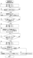
- FIG. 3 is a flowchart showing the power storage control process executed by the control unit 4 in FIG. 1.
- step S1 of FIG. 3 first, switches SW1 to SW6 are set to their initial states. If an abnormal state occurs in power supply unit 1 (YES in S2), power supply (backup operation) from power storage unit 3 to load 2 is started (S3). Then, the amount of charge stored in capacitors C1 to C3 decreases due to the power supply from power storage unit 3. If any one of capacitors C1 to C3 loses charge, no more charge can be supplied even if the other capacitors still have charge remaining. Therefore, voltage detection unit 30 monitors the amount of charge remaining in each of capacitors C1 to C3 by measuring the voltage of each of capacitors C1 to C3.
- the control unit 4 When the control unit 4 detects, through voltage monitoring by the voltage detection unit 30, that the voltage across one or more of the capacitors C1 to C3 has dropped below the threshold voltage Vth1 (YES in S4), the control unit 4 stops the power supply from the power storage unit 3, turns off the switches SW1 and SW2, and turns on the switches SW3 to SW6 (hereinafter referred to as the "parallel connection state of capacitors C1 to C3 by switches SW1 to SW6") (S5), thereby distributing the charge remaining in capacitors C1 to C3 to each of the capacitors C1 to C3, thereby making the amount of charge between the capacitors C1 to C3 uniform (S6). In other words, by giving charge to a capacitor that has lost its charge, it is possible to supply charge again.
- the threshold voltage Vth1 in step S4 is set as follows. In a vehicle power supply device, if the power supply unit 1 fails and the power storage unit 3 falls into an abnormal state in which it cannot supply charge, the control unit 4 will lose its own power source and will be unable to control the charges of the capacitors C1 to C3 of the power storage unit 3 to be equalized.
- the threshold voltage Vth1 of each of the capacitors C1 to C3 is set in a state where surplus power is left to perform charge equalization processing so as to prevent such an abnormal state from occurring. In other words, the threshold voltage Vth1 is set as the voltage across each of the capacitors C1 to C3 before the abnormal state is reached.
- the control unit 4 determines whether the charge equalization of the capacitors C1 to C3 has been completed by the absolute value of the voltage difference between the voltages V1 to V3 across the capacitors C1 to C3 being equal to or less than a predetermined threshold voltage difference ⁇ V through voltage monitoring by the voltage detection unit 30 (S7). If the answer is YES, the control unit 4 proceeds to step S8, whereas if the answer is NO, the control unit 4 returns to step S7. In step S8, the control unit 4 returns the capacitors C1 to C3 to a series connection by returning the switches SW1 to SW6 to their initial states. Then, the control unit 4 determines whether the output voltage Vout of the storage unit 3 is equal to or greater than the threshold voltage Vth2 (S9).
- the threshold voltage Vth2 in step S9 is set as follows:
- the threshold voltage Vth2 is set to an output voltage Vout that is sufficient to operate the system of the load 2 in a normal state after the charges of the capacitors C1 to C3 have been equalized.
- step S10 the load 2 is placed in a state in which DC power can be supplied (standby state) and the power storage control process is terminated. In this case, when the user turns on the ignition, power supply to the load 2 is started, and initial diagnosis such as investigation of the cause of the abnormal state of the vehicle can be performed promptly.
- the voltage of the power storage unit 3 is equal to or lower than the threshold voltage Vth2 (NO in S9), the charge that can be supplied to the load 2 is insufficient and restart is not possible, and the system of the control unit 4 is shut down (S11) and the power storage control process is terminated.
- the vehicle power supply device configured as described above allows the remaining charge to be effectively utilized to supply power to the load 2 (e.g., a vehicle control system) again even in a vehicle power supply device in which the charge balance of the capacitors C1 to C3, which are the multiple storage elements of the storage unit 3, is lost and discharged, causing one capacitor to reach its discharge limit while the other capacitors still have charge remaining. This makes it possible to secure power after a power loss, and allows for rapid initial diagnosis of defective areas.
- the load 2 e.g., a vehicle control system
- the number of capacitors in the power storage unit 3 is described as three, but the present disclosure is not limited to this, and any number greater than two may be used. This also applies to the other embodiments and modified examples.
- FIG. 4 is a block diagram showing an example of the configuration of a power storage unit 3A according to Modification 1.
- the vehicle power supply device in Fig. 4 differs from the vehicle power supply device in Fig. 1 in the following respects.
- a power storage unit 3A is provided, and the power storage unit 3A includes the following resistors R1 to R2 for preventing rush current.
- a resistor R1 is inserted between the switches SW3 and SW4.
- a resistor R2 is inserted between the switch SW3 and one end of the capacitor C3 on the charging circuit 5 side. The differences will be explained below.
- capacitors C1 to C3 are, for example, electric double layer capacitors.
- resistors R1 and R2 are further provided, but the present disclosure is not limited to this, and a configuration may be adopted in which a resistor is connected in parallel to at least one of the multiple capacitors when switches SW3 and SW4 are on. Note that modification 1 and this modification may be applied to other embodiments and modifications.
- FIG. 5 is a block diagram showing an example of the configuration of a vehicle power supply device according to embodiment 2.
- the vehicle power supply device in Fig. 5 differs from the vehicle power supply device in Fig. 1 in the following respects.
- a separate power supply unit 7 is connected to the control unit 4.
- the separate power supply unit 7 is, for example, a battery or a secondary battery such as a lithium ion battery. The differences will be explained below.
- the control unit 4 will lose its own power source and will be unable to perform control to equalize the charges of the capacitors C1 to C3 of the power storage unit 3.
- the threshold voltage Vth1 of each capacitor C1 to C3 is set while leaving surplus power for performing charge equalization processing.
- the vehicle power supply device of embodiment 2 has the same effects as embodiment 1.
- FIG. 6 is a block diagram showing an example of the configuration of a vehicle power supply device according to embodiment 3.
- the vehicle power supply device in Fig. 6 differs from the vehicle power supply device in Fig. 1 in the following respects.
- a vehicle ECU (Electronic Control Unit) 8 is connected to the control unit 4 . The differences will be explained below.
- the control unit 4 communicates with the vehicle ECU 8 via a specified communication line.
- the vehicle ECU 8 is a control device that controls the entire vehicle, and the vehicle power supply device also operates under the control of the vehicle ECU 8.
- the vehicle power supply device is controlled so that it can be restarted at its own discretion, but depending on the vehicle's fault state, it is possible that re-energizing the device may pose a risk of fire or other problems.
- the vehicle ECU 8 collects information on all blocks related to the vehicle, and in the above-mentioned conditions, it is possible to control the vehicle power supply device based on the overall vehicle condition.
- FIG. 7 is a flowchart showing the power storage control process executed by the vehicle ECU 8 and the control unit 4 in FIG. 6.
- control unit 4 executes the processes of steps S1 to S3 in the same manner as in FIG. 3. That is, in step S3, the backup operation from the power storage unit 3 starts, and the charge in the capacitors C1 to C3 is discharged.
- control unit 4 detects that the voltage across one or more of the capacitors C1 to C3 has dropped below the threshold voltage Vth1 (YES in S3), it transmits a cell voltage drop notification signal to the vehicle ECU 8.
- the vehicle ECU 8 receives a cell voltage drop notification signal from the control unit 4 (S31), and if it determines that restart is possible based on the vehicle state (YES in S32), it sends an instruction signal including equalizing the capacitor charge to the control unit 4 (S33). On the other hand, if the vehicle ECU 8 determines that restart is not possible based on the vehicle state (NO in S32), it sends an instruction signal not including equalizing the capacitor charge to the control unit 4 (S34).
- control unit 4 determines whether the instruction signal includes equalization of the capacitor charge (S23), and if YES, proceeds to step S5, whereas if NO, proceeds to step S24. After step S5, the control unit 4 executes the same processes (S5 to S11) as the control process in FIG. 3, and ends the power storage control process. On the other hand, in step S24, it ends the discharge from the power storage unit 3, shuts down the system of the control unit 4, and then ends the power storage control process.
- the communication between the control unit 4 and the vehicle ECU 8 makes it possible to determine whether or not to restart the vehicle depending on the vehicle's condition, which helps prevent secondary disasters.
- the vehicle power supply device according to the third embodiment has the same effects as the vehicle power supply device according to the first or second embodiment.
- Fig. 8 is a block diagram showing an example of the configuration of a vehicle power supply device according to embodiment 4.
- the vehicle power supply device of Fig. 8 differs from the vehicle power supply device of Fig. 1 in the following respects.
- (1) The vehicle ECU 8 according to the third embodiment and the separate power supply unit 7 according to the second embodiment are both included. The differences will be explained below.
- the vehicle power supply device of embodiment 4 configured as described above, even if the power supply unit 1 fails and the power storage unit 3 falls into an abnormal state in which it cannot supply charge, it is possible to equalize the charges of the capacitors C1 to C3, and the vehicle power supply device can be controlled based on the judgment of the vehicle ECU 8. Furthermore, the vehicle power supply device of embodiment 4 has the same effects as the vehicle power supply devices of embodiments 1 to 3.
- the power supply unit 1 and the separate power supply unit 7 are, for example, batteries that supply DC power, but the present disclosure is not limited to this, and AC power may be converted into DC power and supplied. Also, AC power may be supplied and an AC-DC converter may be provided on the power receiving side.
- the vehicle power supply device of the present invention is useful as an auxiliary vehicle power supply for rapid and safe recovery from abnormalities in the power supply unit.
- Power supply unit 2 Load 3 Power storage unit 4 Control unit 5 Charging circuit 6 Voltage conversion circuit 7 Power supply unit 8 Vehicle ECU 30 Voltage detection section C1 to C3 Capacitor SW1 to SW6 Switch R1 to R2 Resistor
Landscapes
- Engineering & Computer Science (AREA)
- Power Engineering (AREA)
- Mechanical Engineering (AREA)
- Transportation (AREA)
- Life Sciences & Earth Sciences (AREA)
- Sustainable Development (AREA)
- Sustainable Energy (AREA)
- Charge And Discharge Circuits For Batteries Or The Like (AREA)
- Stand-By Power Supply Arrangements (AREA)
- Electric Propulsion And Braking For Vehicles (AREA)
Abstract
Description
負荷に電力を供給する電源部と、
前記電源部の異常状態において電力を供給する蓄電部と、
前記蓄電部を充電する充電回路と、
前記蓄電部の電圧を所定の電圧に変換して前記負荷に出力する電圧変換回路と、
前記蓄電部及び前記充電回路及び前記電圧変換回路の動作を制御する制御部とを備え、
前記蓄電部は、
複数のコンデンサと、
前記複数のコンデンサを直列に接続し、もしくは並列に接続することを選択的に切り替える複数のスイッチと、
前記複数のコンデンサのそれぞれの両端電圧を測定する電圧検出部とを備え、
前記制御部は、前記電圧検出部が、前記複数のコンデンサの少なくとも1つのコンデンサがそれ以上の放電が不能となる所定の電圧を前記両端電圧として検出すると、前記複数のスイッチを並列に接続するように制御することで、前記複数のコンデンサのうちの少なくとも1つのコンデンサの残電荷を他のコンデンサに分配し、再び充電することなく前記負荷に再度電力を供給することを可能とした。
図9は従来例に係る車両用電源装置の構成を示すブロック図である。図9において、従来例に係る車両用電源装置は、電源部101と、負荷102と、蓄電部103と、制御部104と、充電回路105と、電圧変換回路106とを備えて構成される。ここで、補助電源として電荷を蓄える蓄電素子には例えば電気二重層キャパシタが用いられ、これらを複数個接続して蓄電部103が構成される。
図1は実施形態1に係る車両用電源装置の構成例を示すブロック図である。図1において、実施形態1に係る車両用電源装置は、電源部1と、負荷2と、蓄電部3と、制御部4と、充電回路5と、電圧変換回路6とを備えて構成される。ここで、電源部1は例えばバッテリなどの二次電池を含み、負荷2は例えば車両制御システムなどの負荷である。また、補助電源として電荷を蓄える蓄電素子には例えば電気二重層キャパシタが用いられ、これらの複数個の電気二重層キャパシタを、例えば直列に接続して蓄電部3が構成される。
(1)電荷を蓄えるコンデンサC1~C3と、
(2)制御部4からの制御のもとでコンデンサC1~C3を直列に接続し又は並列に接続することを選択的に切り替えるスイッチSW1~SW6と、
(3)コンデンサC1~C3の各両端電圧V1~V3及び出力電圧Vout(=V1+V2+V3;コンデンサC3の充電回路5側一端と、接地端子との間の電圧をいう。)を測定して測定結果を制御部4に出力する電圧検出部30と、
を備えて構成される。
図4は変形例1に係る蓄電部3Aの構成例を示すブロック図である。図4の車両用電源装置は、図1の車両用電源装置に比較して以下の点が異なる。
(1)蓄電部3に代えて、蓄電部3Aを備え、蓄電部3Aは、以下のラッシュ電流防止の抵抗R1~R2を備えた。
(A)スイッチSW3とSW4との間に、抵抗R1を挿入した。
(B)スイッチSW3と、コンデンサC3の充電回路5側の一端との間に、抵抗R2を挿入した。
以下、相違点について説明する。
図5は実施形態2に係る車両用電源装置の構成例を示すブロック図である。図5の車両用電源装置は、図1の車両用電源装置に比較して以下の点が異なる。
(1)制御部4に別の電源部7を接続した。ここで、別の電源部7は例えばバッテリ又はリチウムイオンなどの二次電池である。
以下、相違点について説明する。
図6は実施形態3に係る車両用電源装置の構成例を示すブロック図である。図6の車両用電源装置は、図1の車両用電源装置に比較して以下の点が異なる。
(1)制御部4に、車両ECU(Electronic Control Unit)8を接続した。
以下、相違点について説明する。
図8は実施形態4に係る車両用電源装置の構成例を示すブロック図である。図8の車両用電源装置は、図1の車両用電源装置に比較して以下の点が異なる。
(1)実施形態3に係る車両ECU8と、実施形態2に係る別の電源部7とをともに備えた。
以下、相違点について説明する。
以上の実施形態及び変形例において、電源部1及び別の電源部7は例えば直流電力を供給する電池などであるが、本開示はこれに限らず、交流電力を直流電力に変換して供給してもよい。また、交流電力を供給して受電側でACDCコンバータを備えてもよい。
2 負荷
3 蓄電部
4 制御部
5 充電回路
6 電圧変換回路
7 電源部
8 車両ECU
30 電圧検出部
C1~C3 コンデンサ
SW1~SW6 スイッチ
R1~R2 抵抗
Claims (6)
- 負荷に電力を供給する電源部と、
前記電源部の異常状態において電力を供給する蓄電部と、
前記蓄電部を充電する充電回路と、
前記蓄電部の電圧を所定の電圧に変換して前記負荷に出力する電圧変換回路と、
前記蓄電部及び前記充電回路及び前記電圧変換回路の動作を制御する制御部とを備え、
前記蓄電部は、
複数のコンデンサと、
前記複数のコンデンサを直列に接続し、もしくは並列に接続することを選択的に切り替える複数のスイッチと、
前記複数のコンデンサのそれぞれの両端電圧を測定する電圧検出部とを備え、
前記制御部は、前記電圧検出部が、前記複数のコンデンサの少なくとも1つのコンデンサがそれ以上の放電が不能となる所定の電圧を前記両端電圧として検出すると、前記複数のスイッチを並列に接続するように制御することで、前記複数のコンデンサのうちの少なくとも1つのコンデンサの残電荷を他のコンデンサに分配し、再び充電することなく前記負荷に再度電力を供給することを可能とした、車両用電源装置。 - 前記制御部は、前記複数のスイッチを並列に接続するように制御することで、前記複数のコンデンサに蓄えられている電荷量の均一化を実行する、
請求項1に記載の車両用電源装置。 - 前記制御部は、車両ECUの指示に従って前記電荷量の均一化を行う、
請求項2記載の車両用電源装置。 - 前記制御部に接続された別の電源部であって、前記負荷に電力を供給する別の電源部をさらに備え、
前記制御部は前記電荷量の均一化を行う際に、前記別の電源部から電力供給を受ける、
請求項2記載の車両用電源装置。 - 前記複数のコンデンサは電気二重層コンデンサである、
請求項1記載の車両用電源装置。 - 前記蓄電部はさらに、前記複数のコンデンサの少なくとも1つに並列に接続される抵抗であて、前記複数のスイッチを切り替えた際に前記複数のコンデンサに流れるラッシュ電流を抑制する抵抗を備える、
請求項1~5のうちのいずれか1つに記載の車両用電源装置。
Priority Applications (3)
| Application Number | Priority Date | Filing Date | Title |
|---|---|---|---|
| EP23906323.3A EP4641872A4 (en) | 2022-12-22 | 2023-06-27 | VEHICLE ELECTRICAL POWER SUPPLY DEVICE |
| CN202380086932.XA CN120380677A (zh) | 2022-12-22 | 2023-06-27 | 车辆用电源装置 |
| JP2024565586A JPWO2024134937A1 (ja) | 2022-12-22 | 2023-06-27 |
Applications Claiming Priority (2)
| Application Number | Priority Date | Filing Date | Title |
|---|---|---|---|
| JP2022205291 | 2022-12-22 | ||
| JP2022-205291 | 2022-12-22 |
Publications (1)
| Publication Number | Publication Date |
|---|---|
| WO2024134937A1 true WO2024134937A1 (ja) | 2024-06-27 |
Family
ID=91587904
Family Applications (1)
| Application Number | Title | Priority Date | Filing Date |
|---|---|---|---|
| PCT/JP2023/023781 Ceased WO2024134937A1 (ja) | 2022-12-22 | 2023-06-27 | 車両用電源装置 |
Country Status (4)
| Country | Link |
|---|---|
| EP (1) | EP4641872A4 (ja) |
| JP (1) | JPWO2024134937A1 (ja) |
| CN (1) | CN120380677A (ja) |
| WO (1) | WO2024134937A1 (ja) |
Cited By (1)
| Publication number | Priority date | Publication date | Assignee | Title |
|---|---|---|---|---|
| WO2026013994A1 (ja) * | 2024-07-12 | 2026-01-15 | パナソニックIpマネジメント株式会社 | 駆動ユニット及び電動車両 |
Citations (4)
| Publication number | Priority date | Publication date | Assignee | Title |
|---|---|---|---|---|
| JP2001309571A (ja) * | 2000-04-20 | 2001-11-02 | Casio Comput Co Ltd | 充電装置 |
| JP2008219964A (ja) * | 2007-02-28 | 2008-09-18 | Japan Aerospace Exploration Agency | 蓄電モジュール |
| JP2015133817A (ja) * | 2014-01-10 | 2015-07-23 | 萩原電気株式会社 | バックアップ電源装置 |
| JP2020120464A (ja) | 2019-01-22 | 2020-08-06 | 住友電装株式会社 | 車両用電源制御装置、及び車両用電源装置 |
Family Cites Families (2)
| Publication number | Priority date | Publication date | Assignee | Title |
|---|---|---|---|---|
| EP2600486B1 (en) * | 2010-07-27 | 2016-08-17 | Yoshifumi Takeda | Charging control method and discharging control method for electricity storage device |
| EP3026750A1 (de) * | 2014-11-28 | 2016-06-01 | Siemens Aktiengesellschaft | Verfahren zum Symmetrieren eines Energiespeichersystems |
-
2023
- 2023-06-27 CN CN202380086932.XA patent/CN120380677A/zh active Pending
- 2023-06-27 WO PCT/JP2023/023781 patent/WO2024134937A1/ja not_active Ceased
- 2023-06-27 JP JP2024565586A patent/JPWO2024134937A1/ja not_active Withdrawn
- 2023-06-27 EP EP23906323.3A patent/EP4641872A4/en active Pending
Patent Citations (4)
| Publication number | Priority date | Publication date | Assignee | Title |
|---|---|---|---|---|
| JP2001309571A (ja) * | 2000-04-20 | 2001-11-02 | Casio Comput Co Ltd | 充電装置 |
| JP2008219964A (ja) * | 2007-02-28 | 2008-09-18 | Japan Aerospace Exploration Agency | 蓄電モジュール |
| JP2015133817A (ja) * | 2014-01-10 | 2015-07-23 | 萩原電気株式会社 | バックアップ電源装置 |
| JP2020120464A (ja) | 2019-01-22 | 2020-08-06 | 住友電装株式会社 | 車両用電源制御装置、及び車両用電源装置 |
Non-Patent Citations (1)
| Title |
|---|
| See also references of EP4641872A1 |
Cited By (1)
| Publication number | Priority date | Publication date | Assignee | Title |
|---|---|---|---|---|
| WO2026013994A1 (ja) * | 2024-07-12 | 2026-01-15 | パナソニックIpマネジメント株式会社 | 駆動ユニット及び電動車両 |
Also Published As
| Publication number | Publication date |
|---|---|
| EP4641872A4 (en) | 2026-04-08 |
| CN120380677A (zh) | 2025-07-25 |
| EP4641872A1 (en) | 2025-10-29 |
| JPWO2024134937A1 (ja) | 2024-06-27 |
Similar Documents
| Publication | Publication Date | Title |
|---|---|---|
| US9112247B2 (en) | Battery system | |
| JP5660105B2 (ja) | 蓄電システム | |
| US8754654B2 (en) | Power supply device for detecting disconnection of voltage detection lines | |
| US20060021098A1 (en) | Method and apparatus for detecting welding of a relay contact | |
| JP5974849B2 (ja) | 電池監視装置 | |
| US20120146616A1 (en) | Discharger and discharger control method | |
| JP2001309563A (ja) | 建物用電力供給システム及び電池装置 | |
| JP6963729B2 (ja) | 車載用のバックアップ回路及び車載用のバックアップ装置 | |
| JP2002135986A (ja) | 電圧イコライザ装置およびその方法 | |
| JP2013099167A (ja) | 蓄電システムを搭載した車両の制御装置及び制御方法 | |
| CN112046427A (zh) | 车辆供电系统及供电控制方法 | |
| CN112714711B (zh) | 提供冗余电力的系统和方法 | |
| CN110024210A (zh) | 电池控制装置 | |
| JP2020029200A (ja) | 車両用電源システム | |
| US20180015892A1 (en) | Vehicle power supply control device | |
| JP4015126B2 (ja) | 直流電力供給システム | |
| WO2024134937A1 (ja) | 車両用電源装置 | |
| JP2014090635A (ja) | 蓄電システム | |
| JP2025111752A (ja) | 電力装置及びその制御方法 | |
| KR20090092890A (ko) | 배터리 시스템의 배터리 균등 충전장치 | |
| WO2008128296A1 (en) | Battery management system | |
| EP3698153B1 (en) | Method and system for testing a rechargeable battery | |
| JP7658915B2 (ja) | 電力装置及びその制御方法 | |
| CN110739765B (zh) | 直流供电系统 | |
| JP2019221022A (ja) | 電池監視装置、電池監視システム、および電池監視方法 |
Legal Events
| Date | Code | Title | Description |
|---|---|---|---|
| 121 | Ep: the epo has been informed by wipo that ep was designated in this application |
Ref document number: 23906323 Country of ref document: EP Kind code of ref document: A1 |
|
| WWE | Wipo information: entry into national phase |
Ref document number: 2024565586 Country of ref document: JP |
|
| WWE | Wipo information: entry into national phase |
Ref document number: 202380086932.X Country of ref document: CN |
|
| WWE | Wipo information: entry into national phase |
Ref document number: 2023906323 Country of ref document: EP |
|
| NENP | Non-entry into the national phase |
Ref country code: DE |
|
| WWP | Wipo information: published in national office |
Ref document number: 202380086932.X Country of ref document: CN |
|
| ENP | Entry into the national phase |
Ref document number: 2023906323 Country of ref document: EP Effective date: 20250722 |
|
| ENP | Entry into the national phase |
Ref document number: 2023906323 Country of ref document: EP Effective date: 20250722 |
|
| ENP | Entry into the national phase |
Ref document number: 2023906323 Country of ref document: EP Effective date: 20250722 |
|
| WWP | Wipo information: published in national office |
Ref document number: 2023906323 Country of ref document: EP |