WO2024135540A1 - 樹脂被覆金属板及びその製造方法 - Google Patents
樹脂被覆金属板及びその製造方法 Download PDFInfo
- Publication number
- WO2024135540A1 WO2024135540A1 PCT/JP2023/044939 JP2023044939W WO2024135540A1 WO 2024135540 A1 WO2024135540 A1 WO 2024135540A1 JP 2023044939 W JP2023044939 W JP 2023044939W WO 2024135540 A1 WO2024135540 A1 WO 2024135540A1
- Authority
- WO
- WIPO (PCT)
- Prior art keywords
- layer
- resin
- less
- coated metal
- metal plate
- Prior art date
- Legal status (The legal status is an assumption and is not a legal conclusion. Google has not performed a legal analysis and makes no representation as to the accuracy of the status listed.)
- Ceased
Links
Images


Classifications
-
- B—PERFORMING OPERATIONS; TRANSPORTING
- B32—LAYERED PRODUCTS
- B32B—LAYERED PRODUCTS, i.e. PRODUCTS BUILT-UP OF STRATA OF FLAT OR NON-FLAT, e.g. CELLULAR OR HONEYCOMB, FORM
- B32B15/00—Layered products comprising a layer of metal
- B32B15/04—Layered products comprising a layer of metal comprising metal as the main or only constituent of a layer, which is next to another layer of the same or of a different material
- B32B15/08—Layered products comprising a layer of metal comprising metal as the main or only constituent of a layer, which is next to another layer of the same or of a different material of synthetic resin
- B32B15/09—Layered products comprising a layer of metal comprising metal as the main or only constituent of a layer, which is next to another layer of the same or of a different material of synthetic resin comprising polyesters
-
- B—PERFORMING OPERATIONS; TRANSPORTING
- B29—WORKING OF PLASTICS; WORKING OF SUBSTANCES IN A PLASTIC STATE IN GENERAL
- B29C—SHAPING OR JOINING OF PLASTICS; SHAPING OF MATERIAL IN A PLASTIC STATE, NOT OTHERWISE PROVIDED FOR; AFTER-TREATMENT OF THE SHAPED PRODUCTS, e.g. REPAIRING
- B29C43/00—Compression moulding, i.e. applying external pressure to flow the moulding material; Apparatus therefor
- B29C43/003—Compression moulding, i.e. applying external pressure to flow the moulding material; Apparatus therefor characterised by the choice of material
-
- B—PERFORMING OPERATIONS; TRANSPORTING
- B29—WORKING OF PLASTICS; WORKING OF SUBSTANCES IN A PLASTIC STATE IN GENERAL
- B29C—SHAPING OR JOINING OF PLASTICS; SHAPING OF MATERIAL IN A PLASTIC STATE, NOT OTHERWISE PROVIDED FOR; AFTER-TREATMENT OF THE SHAPED PRODUCTS, e.g. REPAIRING
- B29C48/00—Extrusion moulding, i.e. expressing the moulding material through a die or nozzle which imparts the desired form; Apparatus therefor
- B29C48/001—Combinations of extrusion moulding with other shaping operations
- B29C48/0018—Combinations of extrusion moulding with other shaping operations combined with shaping by orienting, stretching or shrinking, e.g. film blowing
-
- B—PERFORMING OPERATIONS; TRANSPORTING
- B29—WORKING OF PLASTICS; WORKING OF SUBSTANCES IN A PLASTIC STATE IN GENERAL
- B29C—SHAPING OR JOINING OF PLASTICS; SHAPING OF MATERIAL IN A PLASTIC STATE, NOT OTHERWISE PROVIDED FOR; AFTER-TREATMENT OF THE SHAPED PRODUCTS, e.g. REPAIRING
- B29C48/00—Extrusion moulding, i.e. expressing the moulding material through a die or nozzle which imparts the desired form; Apparatus therefor
- B29C48/03—Extrusion moulding, i.e. expressing the moulding material through a die or nozzle which imparts the desired form; Apparatus therefor characterised by the shape of the extruded material at extrusion
- B29C48/07—Flat, e.g. panels
- B29C48/08—Flat, e.g. panels flexible, e.g. films
-
- B—PERFORMING OPERATIONS; TRANSPORTING
- B29—WORKING OF PLASTICS; WORKING OF SUBSTANCES IN A PLASTIC STATE IN GENERAL
- B29C—SHAPING OR JOINING OF PLASTICS; SHAPING OF MATERIAL IN A PLASTIC STATE, NOT OTHERWISE PROVIDED FOR; AFTER-TREATMENT OF THE SHAPED PRODUCTS, e.g. REPAIRING
- B29C55/00—Shaping by stretching, e.g. drawing through a die; Apparatus therefor
- B29C55/02—Shaping by stretching, e.g. drawing through a die; Apparatus therefor of plates or sheets
- B29C55/10—Shaping by stretching, e.g. drawing through a die; Apparatus therefor of plates or sheets multiaxial
- B29C55/12—Shaping by stretching, e.g. drawing through a die; Apparatus therefor of plates or sheets multiaxial biaxial
-
- B—PERFORMING OPERATIONS; TRANSPORTING
- B32—LAYERED PRODUCTS
- B32B—LAYERED PRODUCTS, i.e. PRODUCTS BUILT-UP OF STRATA OF FLAT OR NON-FLAT, e.g. CELLULAR OR HONEYCOMB, FORM
- B32B15/00—Layered products comprising a layer of metal
- B32B15/18—Layered products comprising a layer of metal comprising iron or steel
-
- B—PERFORMING OPERATIONS; TRANSPORTING
- B32—LAYERED PRODUCTS
- B32B—LAYERED PRODUCTS, i.e. PRODUCTS BUILT-UP OF STRATA OF FLAT OR NON-FLAT, e.g. CELLULAR OR HONEYCOMB, FORM
- B32B15/00—Layered products comprising a layer of metal
- B32B15/20—Layered products comprising a layer of metal comprising aluminium or copper
-
- B—PERFORMING OPERATIONS; TRANSPORTING
- B32—LAYERED PRODUCTS
- B32B—LAYERED PRODUCTS, i.e. PRODUCTS BUILT-UP OF STRATA OF FLAT OR NON-FLAT, e.g. CELLULAR OR HONEYCOMB, FORM
- B32B27/00—Layered products comprising a layer of synthetic resin
- B32B27/06—Layered products comprising a layer of synthetic resin as the main or only constituent of a layer, which is next to another layer of the same or of a different material
- B32B27/08—Layered products comprising a layer of synthetic resin as the main or only constituent of a layer, which is next to another layer of the same or of a different material of synthetic resin
-
- B—PERFORMING OPERATIONS; TRANSPORTING
- B32—LAYERED PRODUCTS
- B32B—LAYERED PRODUCTS, i.e. PRODUCTS BUILT-UP OF STRATA OF FLAT OR NON-FLAT, e.g. CELLULAR OR HONEYCOMB, FORM
- B32B27/00—Layered products comprising a layer of synthetic resin
- B32B27/18—Layered products comprising a layer of synthetic resin characterised by the use of special additives
-
- B—PERFORMING OPERATIONS; TRANSPORTING
- B32—LAYERED PRODUCTS
- B32B—LAYERED PRODUCTS, i.e. PRODUCTS BUILT-UP OF STRATA OF FLAT OR NON-FLAT, e.g. CELLULAR OR HONEYCOMB, FORM
- B32B27/00—Layered products comprising a layer of synthetic resin
- B32B27/18—Layered products comprising a layer of synthetic resin characterised by the use of special additives
- B32B27/20—Layered products comprising a layer of synthetic resin characterised by the use of special additives using fillers, pigments, thixotroping agents
-
- B—PERFORMING OPERATIONS; TRANSPORTING
- B32—LAYERED PRODUCTS
- B32B—LAYERED PRODUCTS, i.e. PRODUCTS BUILT-UP OF STRATA OF FLAT OR NON-FLAT, e.g. CELLULAR OR HONEYCOMB, FORM
- B32B27/00—Layered products comprising a layer of synthetic resin
- B32B27/36—Layered products comprising a layer of synthetic resin comprising polyesters
-
- C—CHEMISTRY; METALLURGY
- C08—ORGANIC MACROMOLECULAR COMPOUNDS; THEIR PREPARATION OR CHEMICAL WORKING-UP; COMPOSITIONS BASED THEREON
- C08J—WORKING-UP; GENERAL PROCESSES OF COMPOUNDING; AFTER-TREATMENT NOT COVERED BY SUBCLASSES C08B, C08C, C08F, C08G or C08H
- C08J3/00—Processes of treating or compounding macromolecular substances
- C08J3/20—Compounding polymers with additives, e.g. colouring
- C08J3/22—Compounding polymers with additives, e.g. colouring using masterbatch techniques
- C08J3/226—Compounding polymers with additives, e.g. colouring using masterbatch techniques using a polymer as a carrier
-
- C—CHEMISTRY; METALLURGY
- C08—ORGANIC MACROMOLECULAR COMPOUNDS; THEIR PREPARATION OR CHEMICAL WORKING-UP; COMPOSITIONS BASED THEREON
- C08J—WORKING-UP; GENERAL PROCESSES OF COMPOUNDING; AFTER-TREATMENT NOT COVERED BY SUBCLASSES C08B, C08C, C08F, C08G or C08H
- C08J5/00—Manufacture of articles or shaped materials containing macromolecular substances
- C08J5/18—Manufacture of films or sheets
-
- B—PERFORMING OPERATIONS; TRANSPORTING
- B29—WORKING OF PLASTICS; WORKING OF SUBSTANCES IN A PLASTIC STATE IN GENERAL
- B29C—SHAPING OR JOINING OF PLASTICS; SHAPING OF MATERIAL IN A PLASTIC STATE, NOT OTHERWISE PROVIDED FOR; AFTER-TREATMENT OF THE SHAPED PRODUCTS, e.g. REPAIRING
- B29C43/00—Compression moulding, i.e. applying external pressure to flow the moulding material; Apparatus therefor
- B29C43/02—Compression moulding, i.e. applying external pressure to flow the moulding material; Apparatus therefor of articles of definite length, i.e. discrete articles
- B29C43/18—Compression moulding, i.e. applying external pressure to flow the moulding material; Apparatus therefor of articles of definite length, i.e. discrete articles incorporating preformed parts or layers, e.g. compression moulding around inserts or for coating articles
-
- B—PERFORMING OPERATIONS; TRANSPORTING
- B29—WORKING OF PLASTICS; WORKING OF SUBSTANCES IN A PLASTIC STATE IN GENERAL
- B29K—INDEXING SCHEME ASSOCIATED WITH SUBCLASSES B29B, B29C OR B29D, RELATING TO MOULDING MATERIALS OR TO MATERIALS FOR MOULDS, REINFORCEMENTS, FILLERS OR PREFORMED PARTS, e.g. INSERTS
- B29K2305/00—Use of metals, their alloys or their compounds, as reinforcement
- B29K2305/02—Aluminium
-
- B—PERFORMING OPERATIONS; TRANSPORTING
- B32—LAYERED PRODUCTS
- B32B—LAYERED PRODUCTS, i.e. PRODUCTS BUILT-UP OF STRATA OF FLAT OR NON-FLAT, e.g. CELLULAR OR HONEYCOMB, FORM
- B32B2264/00—Composition or properties of particles which form a particulate layer or are present as additives
- B32B2264/02—Synthetic macromolecular particles
- B32B2264/0214—Particles made of materials belonging to B32B27/00
- B32B2264/0257—Polyolefin particles, e.g. polyethylene or polypropylene homopolymers or ethylene-propylene copolymers
-
- B—PERFORMING OPERATIONS; TRANSPORTING
- B32—LAYERED PRODUCTS
- B32B—LAYERED PRODUCTS, i.e. PRODUCTS BUILT-UP OF STRATA OF FLAT OR NON-FLAT, e.g. CELLULAR OR HONEYCOMB, FORM
- B32B2307/00—Properties of the layers or laminate
- B32B2307/50—Properties of the layers or laminate having particular mechanical properties
- B32B2307/514—Oriented
- B32B2307/518—Oriented bi-axially
-
- B—PERFORMING OPERATIONS; TRANSPORTING
- B32—LAYERED PRODUCTS
- B32B—LAYERED PRODUCTS, i.e. PRODUCTS BUILT-UP OF STRATA OF FLAT OR NON-FLAT, e.g. CELLULAR OR HONEYCOMB, FORM
- B32B2311/00—Metals, their alloys or their compounds
- B32B2311/30—Iron, e.g. steel
-
- B—PERFORMING OPERATIONS; TRANSPORTING
- B32—LAYERED PRODUCTS
- B32B—LAYERED PRODUCTS, i.e. PRODUCTS BUILT-UP OF STRATA OF FLAT OR NON-FLAT, e.g. CELLULAR OR HONEYCOMB, FORM
- B32B37/00—Methods or apparatus for laminating, e.g. by curing or by ultrasonic bonding
- B32B37/10—Methods or apparatus for laminating, e.g. by curing or by ultrasonic bonding characterised by the pressing technique, e.g. using action of vacuum or fluid pressure
-
- C—CHEMISTRY; METALLURGY
- C08—ORGANIC MACROMOLECULAR COMPOUNDS; THEIR PREPARATION OR CHEMICAL WORKING-UP; COMPOSITIONS BASED THEREON
- C08J—WORKING-UP; GENERAL PROCESSES OF COMPOUNDING; AFTER-TREATMENT NOT COVERED BY SUBCLASSES C08B, C08C, C08F, C08G or C08H
- C08J2367/00—Characterised by the use of polyesters obtained by reactions forming a carboxylic ester link in the main chain; Derivatives of such polymers
-
- C—CHEMISTRY; METALLURGY
- C08—ORGANIC MACROMOLECULAR COMPOUNDS; THEIR PREPARATION OR CHEMICAL WORKING-UP; COMPOSITIONS BASED THEREON
- C08J—WORKING-UP; GENERAL PROCESSES OF COMPOUNDING; AFTER-TREATMENT NOT COVERED BY SUBCLASSES C08B, C08C, C08F, C08G or C08H
- C08J2367/00—Characterised by the use of polyesters obtained by reactions forming a carboxylic ester link in the main chain; Derivatives of such polymers
- C08J2367/02—Polyesters derived from dicarboxylic acids and dihydroxy compounds
-
- C—CHEMISTRY; METALLURGY
- C08—ORGANIC MACROMOLECULAR COMPOUNDS; THEIR PREPARATION OR CHEMICAL WORKING-UP; COMPOSITIONS BASED THEREON
- C08K—Use of inorganic or non-macromolecular organic substances as compounding ingredients
- C08K3/00—Use of inorganic substances as compounding ingredients
- C08K3/18—Oxygen-containing compounds, e.g. metal carbonyls
- C08K3/20—Oxides; Hydroxides
- C08K3/22—Oxides; Hydroxides of metals
- C08K2003/2237—Oxides; Hydroxides of metals of titanium
- C08K2003/2241—Titanium dioxide
Definitions
- the present invention relates to a resin-coated metal sheet and a method for manufacturing the same.
- metal sheets such as TFS (tin-free steel) and aluminum used as materials for metal containers are painted to improve corrosion resistance and weather resistance.
- This painting has the problem that the painting and baking processes require a huge amount of processing time.
- a large amount of solvent is discharged, which is a problem in terms of environmental impact. Therefore, in order to solve these problems, there are increasing examples of using laminated steel sheets, in which a resin layer is formed by covering the surface of a metal sheet with a thermoplastic resin film.
- Laminated steel sheets are widely used, for example, in the field of beverage cans and food cans, which require a high degree of molding.
- the resin layer located on the outer surface of the container may be printed to improve the design.
- Patent Document 1 discloses a resin-coated metal sheet for containers.
- This resin-coated metal sheet for containers has a resin coating layer on both sides of the metal sheet.
- the resin coating layer located on the outer surface side of the container after molding is mainly composed of polyester resin with a melting point in the range of 230°C to 254°C and also contains a lubricating component, the melting point of which is 80°C to 230°C, and the average particle size of the lubricating component present on the surface of the resin coating layer is 17.0 nm or less.
- Patent Document 1 also discloses that drawing and DI (drawing and ironing) methods may be used to process resin-coated metal sheets for containers. It also describes that white pigments may be added to the resin coating layer located on the outer surface of the container after molding, in order to improve the design and aesthetics of the can body after printing.
- drawing and DI drawing and ironing
- Adding a lubricating component to the resin layer that coats the metal sheet suppresses breakage and abrasion of the resin layer, ensuring good formability.
- the lubricating component can reduce the adhesion between the resin layer and the metal sheet, which can cause the resin layer to peel off from the metal sheet during can manufacturing. Such peeling is problematic because it can cause poor molding during can manufacturing and a decrease in corrosion resistance and weather resistance afterwards.
- the lubricating component can reduce the adhesion of the printing ink used for printing to the resin layer, which can cause the ink to peel off during can manufacturing. Ink peeling is problematic because it impairs the design and beauty of the can body's appearance. Therefore, it is desirable to provide a resin-coated metal sheet that has excellent formability and adhesion of the resin layer, as well as excellent ink adhesion.
- the present invention was made in consideration of the above-mentioned circumstances, and its purpose is to provide a resin-coated metal plate with excellent formability and adhesion of the resin layer as well as ink adhesion, and a method for manufacturing the same.
- the resin-coated metal sheet according to the present invention which is intended to achieve the above object, is as follows:
- the resin-coated metal sheet is A metal plate layer; A resin layer containing a polyester resin covering the plate surface of the metal plate layer, The resin layer is Its melting point is 225°C or higher and 255°C or lower, A surface layer disposed on a surface opposite to the side facing the metal plate layer; A lower layer facing the metal plate layer; and an intermediate layer between the surface layer and the lower layer, the surface layer containing a lubricating component made of a polyolefin having a melting point of 75° C. or more and 140° C.
- the coverage of the lubricating component exposed on the surface of the surface layer is 0.040% or more and 0.80% or less, as determined by peak intensity ratio analysis of Raman spectrum data obtained when Raman measurement is performed on the surface layer using a confocal Raman device.
- the resin-coated metal sheet according to the present invention may further be as follows:
- the surface layer has a layer thickness of 1.0 ⁇ m or more and 5.0 ⁇ m or less
- the intermediate layer has a thickness of 6.0 ⁇ m or more and 30 ⁇ m or less
- the resin-coated metal sheet described in any one of [1] to [7] above can be manufactured by the following manufacturing method.
- a master batch pellet is prepared by dispersing the lubricating component in a polyester resin having a melting point of 230° C. or more and 254° C. or less and an intrinsic viscosity of 0.45 or more and 0.88 or less, The master batch pellets and polyester resin pellets are mixed and kneaded, extruded at a predetermined extrusion temperature, and stretched by a biaxial stretching method to form a film. The film is thermocompression bonded to a metal plate by a laminating roll.
- the present invention provides a resin-coated metal plate with excellent formability and adhesion of the resin layer and ink adhesion, and a method for manufacturing the same.
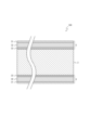
- FIG. 1 is a cross-sectional view illustrating a structure of a resin-coated metal sheet according to an embodiment of the present invention.
- FIG. 4 is a cross-sectional view illustrating a structure of a resin-coated metal sheet according to another embodiment of the present invention.
- FIG. 4 is a cross-sectional view illustrating a structure of a resin-coated metal sheet according to another embodiment of the present invention.
- FIG. 1 shows a cross-sectional view of a resin-coated metal plate 100 (hereinafter referred to as plate material 100) according to this embodiment.
- the plate material 100 comprises a metal plate layer 2 and a resin layer 3 containing polyester resin that covers the plate surface of the metal plate layer 2.
- the resin layer 3 has a surface layer 31 arranged on the surface opposite to the side facing the metal plate layer 2, a lower layer 33 facing the metal plate layer 2, and an intermediate layer 32 located between the surface layer 31 and the lower layer 33.
- the melting point of the resin layer 3 is 225°C or higher and 255°C or lower.
- the surface layer 31 contains a lubricating component made of polyolefin having a melting point of 75°C or higher and 140°C or lower.
- the coverage of the lubricating component exposed on the surface of the surface layer 31 is 0.040% or higher and 0.80% or lower. This coverage is determined by peak intensity ratio analysis of Raman spectrum data obtained when Raman measurement is performed on the surface layer 31 using a confocal Raman device.
- FIG. 1 shows a case where the plate material 100 further includes a resin layer 4.
- the plate material 100 will be described in detail below.
- the metal plate layer 2 is a layer of a metal plate.
- the metal plate layer 2 is, for example, a steel plate such as tinplate or TFS.
- tinplate it is preferable to use one having a plating amount in the range of 0.5 g/m 2 or more and 15 g/m 2 or less.
- TFS it is preferable to have a metal chromium layer having a metal chromium adhesion amount of 50 mg/m 2 or more and 200 g/m 2 or less and a chromium oxide layer having a metal chromium equivalent chromium oxide adhesion amount of 3 mg/m 2 or more and 30 g/m 2 or less on the surface.
- the steel plate may have a plating or chromium oxide layer on both sides, only one side, or only a part of the steel plate.
- the steel plate has a plating or chromium oxide layer only on one side or only a part of the steel plate, it is preferable to provide the resin layer 3 on at least the surface part of the steel plate where no plating or chromium oxide layer is present.
- the type of steel plate is not particularly important as long as it can be formed into the desired shape, but it is preferable to use one with the following composition and manufactured using the following manufacturing method.
- the steel plate is made of low-carbon steel with a C content (carbon content) in the range of 0.010 mass% to 0.10 mass%, and is recrystallized by continuous annealing.
- the steel plate is made of low carbon steel with a C content in the range of 0.010 mass% or more and 0.10 mass% or less, and that the steel plate is recrystallized by continuous annealing and overaged.
- low-carbon steel with a C content in the range of 0.010 mass% or more and 0.10 mass% or less, and to perform recrystallization annealing by box annealing.
- low carbon steel with a C content in the range of 0.010 mass% or more and 0.10 mass% or less, and to subject the steel to recrystallization annealing by continuous annealing or box annealing, followed by secondary cold rolling.
- IF Interstitial Free steel, which is made by adding elements such as Nb and Ti that fix the C dissolved in ultra-low carbon steel with a C content of about 0.003 mass% or less, and then recrystallizing it by continuous annealing.
- the mechanical properties of the steel sheet there are no particular limitations on the mechanical properties of the steel sheet, so long as it can be formed into the desired shape.
- a steel sheet with a yield point (YP) in the range of approximately 220 MPa to 580 MPa.
- the Lankford value (r value) which is an index of plastic anisotropy, is preferably 0.8 or more.
- the absolute value of the in-plane anisotropy ⁇ r of the r value is 0.7 or less.
- the steel components for satisfying the above mechanical properties are not particularly limited, but may contain, for example, components such as Si, Mn, P, S, Al, and N. It is preferable that the Si content is 0.001% by mass or more and 0.1% by mass or less, the Mn content is 0.01% by mass or more and 0.6% by mass or less, the P content is 0.002% by mass or more and 0.05% by mass or less, the S content is 0.002% by mass or more and 0.05% by mass or less, the Al content is 0.005% by mass or more and 0.100% by mass or less, and the N content is 0.0005% by mass or more and 0.020% by mass or less.
- other components such as Ti, Nb, B, Cu, Ni, Cr, Mo, and V may be contained, but from the viewpoint of ensuring corrosion resistance, etc., it is preferable that the total content of these components is 0.02% by mass or less.
- the resin layer 3 has a surface layer 31, an intermediate layer 32, and a lower layer 33.
- the surface layer 31 is the outermost layer
- the lower layer 33 is the bottom layer in the resin layer 3.
- the resin layer 3 has a melting point of 225°C or more and 255°C or less, and contains polyester resin as a main component.
- the melting point of the resin layer 3 is 232°C or more and 252°C or less. More preferably, the melting point of the resin layer 3 is 238°C or more and 250°C or less. If the melting point of the resin layer 3 is less than 225°C, the resin softens due to the heat applied to the resin during molding, causing breakage or chipping of the resin layer 3, and reducing moldability. On the other hand, if the melting point of the resin layer 3 exceeds 255°C, the crystallinity of the polyester resin becomes high, making the resin layer 3 more likely to break or chip during molding, and reducing moldability.
- dicarboxylic acid components and glycol components may be used as raw materials for polyester resins.
- multiple dicarboxylic acid components and glycol components may be copolymerized within a range that does not impair heat resistance or processability.
- dicarboxylic acid components include aromatic dicarboxylic acids such as terephthalic acid, isophthalic acid, naphthalenedicarboxylic acid, diphenyldicarboxylic acid, diphenylsulfonedicarboxylic acid, diphenoxyethanedicarboxylic acid, 5-sodium sulfoisophthalic acid, and phthalic acid, aliphatic dicarboxylic acids such as oxalic acid, succinic acid, adipic acid, sebacic acid, dimer acid, maleic acid, and fumaric acid, alicyclic dicarboxylic acids such as cyclohexanedicarboxylic acid, and oxycarboxylic acids such as p-oxybenz
- glycol components include aliphatic glycols such as ethylene glycol, propanediol, butanediol, pentanediol, hexanediol, and neopentyl glycol, alicyclic glycols such as cyclohexanedimethanol, aromatic glycols such as bisphenol A and bisphenol S, and diethylene glycol.
- aliphatic glycols such as ethylene glycol, propanediol, butanediol, pentanediol, hexanediol, and neopentyl glycol
- alicyclic glycols such as cyclohexanedimethanol
- aromatic glycols such as bisphenol A and bisphenol S
- diethylene glycol diethylene glycol
- the surface layer 31 and the lower layer 33 may be formed from resin extruded using a single extruder.
- the surface layer 31 and the lower layer 33 have the same composition, and not only the outermost surface layer 31 but also the lower layer 33 at the bottom will contain a lubricating component.
- the surface layer 31 and the lower layer 33 may be formed from resins of the same or different compositions extruded using two separate extruders.
- a lubricating component made of polyolefin having a melting point of 75°C to 140°C is used because of its excellent film-forming and dispersibility.
- the polyolefin has a polar group.
- examples of polyolefins having a polar group include acid-modified polyolefins such as ethylene maleic anhydride copolymers, oxidized polyolefins such as polyethylene oxide, and ethylene acrylic acid copolymers, and one of these can be used alone or two or more can be used in combination.
- the affinity between the lubricating component and the resin layer 3 changes depending on the acid value of the polyolefin constituting the lubricating component. For example, the higher the acid value of the polyolefin constituting the lubricating component, the higher the affinity between the lubricating component and the resin layer 3. When the affinity is high, the dispersed particle size of the lubricating component on the surface of the resin layer 3 becomes smaller, and the coverage of the lubricating component obtained by peak intensity ratio analysis of Raman spectrum data tends to decrease.
- the melting point of the lubricating component is preferably 90°C or higher and 130°C or lower, and more preferably 100°C or higher and 120°C or lower. If the melting point of the lubricating component is lower than 75°C, the lubricating component is likely to thicken on the surface of the resin layer 3 due to the process of coating the resin layer 3 on the metal plate layer 2 and the heat treatment performed during molding of the resin-coated metal plate. In addition, many of the lubricating components are likely to melt due to the heat during processing. Therefore, the resin layer 3 may be scraped during processing in a mold, and moldability may decrease.
- the low affinity between the lubricating component and the printing ink may inhibit the adhesion of the printing ink, and the printing ink may peel off during molding. Furthermore, if the melting point of the lubricating component exceeds 140°C, sufficient slipperiness and abrasion resistance cannot be ensured, and the resin layer 3 may break or be scraped during molding, resulting in a decrease in moldability.
- the coverage of the lubricating component exposed on the outermost surface of the resin layer 3, i.e., the surface of the surface layer 31 is 0.040% or more and 0.80% or less. It is preferably 0.060% or more and 0.70% or less, more preferably 0.070% or more and 0.65% or less, and even more preferably 0.080% or more and 0.50% or less.
- the coverage is determined by peak intensity ratio analysis of Raman spectrum data obtained when performing Raman measurement on surface layer 31 using a confocal Raman device (hereinafter, also simply referred to as "this measurement method").
- This measurement method makes it possible to calculate the dispersion state of the lubricating components non-destructively and with high resolution, and it is possible to capture even minute lubricating components on the surface of surface layer 31 that cannot be captured by other analytical methods.
- the coverage rate of the lubricating component exposed on the outermost surface of the resin layer 3 is very low, less than 0.040%, sufficient slipperiness and abrasion resistance to withstand processing during can manufacturing cannot be ensured, and breakage and abrasion may occur during molding, resulting in reduced formability. Furthermore, if the coverage rate of the lubricating component exposed on the outermost surface of the resin layer 3 is excessive, exceeding 0.80%, the lubricating component may inhibit the adhesion of the printing ink, causing the printing ink to peel off during molding.
- the coverage rate is affected by the content and dispersion state or dispersibility of the lubricating component in the surface layer 31. Therefore, in order to improve the dispersion state of the lubricating component in the surface layer 31, it is preferable to use a master batch when forming the film that constitutes the surface layer 31 or the resin layer 3.
- the master batch is a polyester resin in which a lubricating component is dispersed at a high concentration.
- the melting point of the polyester resin that is the base of the master batch is preferably 230°C or higher and 254°C or lower, more preferably 234°C or higher and 252°C or lower, and even more preferably 238°C or higher and 250°C or lower.
- the intrinsic viscosity of the polyester resin that is the base of the masterbatch is preferably 0.45 or more and 0.88 or less, more preferably 0.50 or more and 0.85 or less, and even more preferably 0.55 or more and 0.80 or less.
- the melting point of the lubricating component used in the master batch is 75°C or higher and 140°C or lower, preferably 90°C or higher and 130°C or lower, and more preferably 100°C or higher and 120°C or lower.
- the acid value of the lubricating component used in the master batch is preferably 1.0 mgKOH/g or more and 80 mgKOH/g or less. More preferably, it is 1.0 mgKOH/g or more and 60 mgKOH/g or less, and even more preferably, it is 2.0 mgKOH/g or more and 45 mgKOH/g or less.
- the resin layer 3 is preferably formed of a resin material containing 90 mol% or more of ethylene terephthalate units.
- the content of ethylene terephthalate units in the resin material is more preferably 92 mol% or more, and even more preferably 95 mol% or more.
- the melting point of the resin layer 3 is sufficiently high. Therefore, the thermal deterioration of the resin material due to the heat treatment performed during the process of coating the resin layer 3 on the metal plate layer 2 and during the molding process of the resin-coated metal plate is suppressed, and the moldability of the resin layer 3 is improved.
- the resin layer 3 as a whole satisfies the above content of ethylene terephthalate units, and the surface layer 31, the intermediate layer 32, and the lower layer 33 may be formed of polyester resin materials of the same composition or polyester resin materials of different compositions.
- the lubricating component contained in the surface layer 31 of the resin layer 3 is preferably 0.10% by mass or more and 1.0% by mass or less. More preferably, it is 0.20% by mass or more and 0.90% by mass or less, and even more preferably, it is 0.40% by mass or more and 0.80% by mass or less.
- the coverage rate of the lubricating component exposed on the surface of the surface layer 31 falls within the appropriate range, so that sufficient slipperiness and abrasion resistance can be ensured during molding, and the resin layer 3 does not break or chip. Furthermore, sufficient ink adhesion can be ensured, and ink peeling does not occur during molding.
- the lower layer 33 may optionally contain a lubricating component in a content within the above range, similar to the surface layer 31. If the content of the lubricating component is within the above range, the adhesion between the lower layer 33 and the metal plate layer 2 can be sufficiently ensured, and peeling of the resin layer 3 is less likely to occur during molding.
- the intermediate layer 32 may contain a lubricating component in an amount within the above range, but from a cost perspective, it is preferable that the intermediate layer 32 does not contain a lubricating component.
- the acid value of the lubricating component is preferably 1.0 mgKOH/g or more and 80 mgKOH/g or less, more preferably 1.0 mgKOH/g or more and 60 mgKOH/g or less, and even more preferably 2.0 mgKOH/g or more and 45 mgKOH/g or less.
- affinity with the resin layer 3 and the printing ink can be sufficiently ensured, and the adhesion of the printing ink can be improved.
- the lubricating component is not compatible with the polyester resin that forms the resin layer 3 and softening and deterioration of the resin layer 3 can be suppressed, sufficient slip properties and abrasion resistance can be ensured during molding processing, and the resin layer 3 does not break or chip, resulting in good moldability.
- the resin layer 3 may be required to be white in order to improve the design and beauty of the can body appearance after printing. If it is desired to make the resin layer 3 white, it is preferable to include 10% to 30% by mass of inorganic particles in the intermediate layer 32.
- the content of inorganic particles in the intermediate layer 32 is more preferably 10% to 25% by mass, and even more preferably 15% to 20% by mass.
- the resin layer 3 can ensure sufficient whiteness and hiding power.
- the resin layer 3 is less likely to break or chip during processing during can manufacturing, and has good moldability.
- the content of inorganic particles is the amount relative to 100% by mass of the resin composition (including polyester resin material and inorganic particles) for forming the intermediate layer 32.
- the inorganic particles contained in the intermediate layer 32 it is preferable to use rutile-type titanium oxide ( TiO2 ) with a purity of 90% or more.
- TiO2 rutile-type titanium oxide
- the titanium oxide exhibits good dispersibility when mixed with the resin material, resulting in a uniform whiteness and improving the design and beauty of the appearance.
- the resin layer 3 is not limited to a three-layer structure, and may be a laminated structure of four or more layers, so long as it has a surface layer 31, a lower layer 33, and an intermediate layer 32.
- the resin layer 3 can be made into a laminated structure of four or more layers.
- the layer thicknesses (film thicknesses) of the surface layer 31, the intermediate layer 32, and the lower layer 33 are as follows:
- the thickness of the surface layer 31 is preferably 1.0 ⁇ m or more and 5.0 ⁇ m or less, more preferably 1.5 ⁇ m or more and 4.0 ⁇ m or less, and even more preferably 2.0 ⁇ m or more and 3.0 ⁇ m or less.
- the thickness of the surface layer 31 is within the above range, sufficient slipperiness and abrasion resistance can be ensured during molding, and the resin layer 3 is less likely to break or be abraded, resulting in good moldability.
- sufficient whiteness can be ensured, improving the design and beauty of the appearance.
- the thickness of the lower layer 33 is preferably 1.0 ⁇ m or more and 5.0 ⁇ m or less, more preferably 1.5 ⁇ m or more and 4.0 ⁇ m or less, and even more preferably 2.0 ⁇ m or more and 3.0 ⁇ m or less.
- the thickness of the lower layer 33 is within the above range, the overall thickness of the resin layer 3 falls within the appropriate range, so that sufficient abrasion resistance can be ensured during molding.
- the lower layer 33 contains a lubricating component
- the absolute amount of the lubricating component dispersed to the surface on the metal plate layer 2 side falls within the appropriate range, so that the adhesion between the resin layer 3 and the metal plate layer 2 is improved.
- the thickness of the intermediate layer 32 is preferably 6.0 ⁇ m or more and 30 ⁇ m or less, more preferably 8.0 ⁇ m or more and 25 ⁇ m or less, and even more preferably 10 ⁇ m or more and 20 ⁇ m or less.
- the thickness of the intermediate layer 32 is within the above range, there is no need to vary the thicknesses of the surface layer 31 and the lower layer 33, and the increase or decrease in the absolute amount of the lubricating component is suppressed. Therefore, the coverage rate of the lubricating component tends to be within an appropriate range, peeling, breaking, or scraping does not occur in the resin layer 3 during molding processing, and the adhesion of the printing ink to the resin layer 3 can be improved.
- the method for producing the film for forming the resin layer 3 can be a general laminated film production technique, such as co-extrusion or film lamination. From the viewpoint of simplifying the production process, it is preferable to produce the film by co-extrusion.
- the production of the film by co-extrusion can be performed, for example, as follows. Using a multi-layer die, the resin compositions for each layer are co-extruded from the extruders for each layer to produce a non-stretched laminated film, which is then stretched to produce a film. It is preferable to perform film production by stretching the non-stretched laminated film in two directions, once in the film-making direction and then once in the direction perpendicular to the film-making direction.
- the resin compositions may be co-extruded from the extruder for the intermediate layer 32 and the extruders for the surface layer 31 and the lower layer 33 to produce a non-stretched laminated film.
- the method of incorporating the lubricating component into the surface layer 31 is not particularly limited, but as an example, the lubricating component may be added as follows.
- a master batch master batch pellets
- the polyester resin pellets which are the main component of the resin layer 3
- the resulting resin composition is introduced into the extruder for the surface layer 31 and extruded at a predetermined extrusion temperature to form the surface layer 31.
- the above-mentioned predetermined extrusion temperature it is preferable to adjust the above-mentioned predetermined extrusion temperature to 255°C or higher and 285°C or lower, which is 30°C higher than the melting point of the resin pellets.
- the extrusion temperature In order to improve the dispersion of the lubricating component in the layer of the resin layer 3 that contains the lubricating component, at least in the surface layer 31, it is preferable to adjust the extrusion temperature to a higher temperature within the above temperature range.
- the stretching ratio after the non-stretched laminate film is produced is preferably 2.0 times or more and 5.0 times or less in both the longitudinal and transverse directions, and more preferably 3.0 times or more and 4.5 times or less.
- the temperature of the kneading extrusion during the preparation of the master batch and the screw rotation speed of the extruder may be adjusted.
- the coating of the metal plate layer 2 with the film that serves as the resin layer 3 may be performed by thermocompression bonding the film to the metal plate layer 2 using a lamination roll.
- the resin layer 4 is a layer formed on the surface of the plate material 100 opposite to the resin layer 3.
- the resin layer 4 is, for example, a layer containing polyester resin.
- the resin layer 4 is not essential for the plate material 100, and as shown in FIG. 2, the plate material 100 may not have the resin layer 4.
- the resin layer 4 may be a single layer as shown in FIG. 1, or may be formed as a multilayer of two or more layers. In the plate material 100, the resin layer 4 does not need to be a layer having a structure different from the resin layer 3, and as shown in FIG. 3, the resin layer 3 may be formed on both sides of the plate material 100. That is, the plate material 100 may have the resin layer 3 (see FIG. 3) as the resin layer 4 (see FIG. 1).
- the resin-coated metal sheets of Examples 1 to 28 and Comparative Examples 1 to 8 were manufactured as follows.
- a TFS having a thickness of 0.22 mm, a metallic chromium layer of 120 mg/m 2 , a chromium oxide layer of 10 mg/m 2 calculated as metallic chromium, and a temper of T3CA was prepared.
- a three-layer resin layer having a surface layer, an intermediate layer, and a lower layer was formed as follows, using the recipes and conditions shown in Tables 1 to 3.
- a film to be used as the resin layer was produced using the recipes shown in Tables 1 to 3, with the extrusion temperature during kneading of the resin pellets and the master batch being 275°C.
- the film was stretched by a biaxial stretching method, stretching 4.0 times in both the longitudinal and transverse directions.
- the metal plate was heated, the film was thermocompressed to the metal plate with a laminating roll, and water-cooled in a water-cooled tank 1.5 seconds after thermocompression, to produce a resin-coated metal plate in which both sides of the metal plate were coated with a resin layer.
- Table 1 shows the recipes and production conditions for the resin-coated metal plates of Examples 1 to 13, and Table 2 shows the recipes and production conditions for the resin-coated metal plates of Examples 14 to 24.
- Table 3 shows the recipes and production conditions for the resin-coated metal plates of Examples 25 to 28 and Comparative Examples 1 to 8.
- descriptions such as "Ethylene terephthalate 90, ethylene isophthalate 10" (quoted from Example 1) in the "Resin composition [mol %]" column mean that the content of ethylene terephthalate units in the resin material forming the resin layer is 90 mol % and the content of ethylene isophthalate units is 10 mol %.
- the melting point of the resin layer, the melting point of the lubricating component, the coverage of the lubricating component exposed on the outermost surface (surface layer) of the resin layer, the resin composition of the resin layer, the acid value of the lubricating component, and the film thickness of the resin layer were measured using the methods described below.
- the melting point of lubricating component was determined as follows. The resin layer was peeled off from the resin-coated metal plate as described above in (1), and the resin layer was dissolved using hexafluoro-2-propanol as a solvent. The solution was centrifuged and then pressure-filtered with filters having pore sizes of 1 ⁇ m and 0.1 ⁇ m in order to extract the lubricating components contained in the surface layer and the lower layer. Furthermore, the above filter was subjected to Soxhlet extraction using xylene as a solvent, and the lubricating components were additionally extracted by concentration, reprecipitation, and centrifugation.
- the lubricating components extracted as described above were measured using a differential scanning calorimeter: DSCQ100 manufactured by TA Instruments under the conditions of an atmospheric gas of N2 , a flow rate of 50 ml/min, a temperature range of room temperature to 290 ° C, and a heating rate of 10 ° C/min.
- the peak top temperature of the endothermic peak in the range of 50 ° C to 170 ° C of the obtained heat flow was taken as the melting point.
- the measurement range was 50 ⁇ m (lamination direction of the resin-coated metal sheet) ⁇ 50 ⁇ m (direction perpendicular to the lamination direction within the plate surface of the resin-coated metal sheet).
- the measurement pitch was 0.5 ⁇ m in both the lamination direction and the direction perpendicular to the lamination direction within the plate surface.
- the measurement was carried out on three randomly selected visual fields for each resin-coated metal plate, and all lubricating components within the measured visual fields were used as the calculation target.
- the resin composition of the resin layer was calculated as follows. After peeling the resin layer from the resin-coated metal plate in the same manner as in (1) above, the resin layer was dissolved in a solvent obtained by adding an appropriate amount of trifluoroacetic acid-d to chloroform-d. At this time, in order to remove the insoluble matter generated during the dissolution process, centrifugation was performed and the soluble matter was used for measurement. The measurement was performed using a nuclear magnetic resonance apparatus: AVANCE NEO cryo-500 type manufactured by Bruker Biospin Co., Ltd., under the conditions of a measurement nucleus of 1 H (500 MHz) and an accumulation number of 16 times. The resin composition ratio was calculated from the integral intensity of each signal in the obtained spectrum.
- Acid value of lubricating component was calculated as follows.
- the lubricating component extracted in the same manner as in (2) above was weighed into a flask in a predetermined amount according to the estimated acid value in accordance with JIS K5902, and dissolved in 100 mL of a neutral solvent.
- the neutral solvent was a mixture of diethyl ether specified in JIS K8103 and ethanol specified in JIS K8101 (purity 99.5 or higher) in a volume ratio of 1:1 or 2:1.
- Each layer thickness of the resin layer was obtained as follows. After peeling the resin layer from the resin-coated metal plate in the same manner as in (1) above, a Pt coat was applied to the outermost surface of the resin layer, and a cross section was prepared using an ion milling device: EM TIC 3X manufactured by Leica Microsystems Co., Ltd. Then, using a scanning electron microscope (SEM): Regulus 8220 manufactured by Hitachi High-Technologies Corporation, a backscattered electron image was observed under two conditions of observation magnifications of 2500 times and 8000 times, and the thicknesses of the surface layer, middle layer, and lower layer of the resin layer were calculated from the observed image.
- SEM scanning electron microscope
- the film adhesion was evaluated as follows.
- the resin-coated metal sheets of Examples 1 to 28 and Comparative Examples 1 to 8 were molded into can bodies (cylinders with a diameter of 50 mm and a height of 160 mm), and then test pieces were cut out in a T-shape from the upper position of the can body.
- the resin layer and the metal sheet, which are the non-target surfaces were cut with a score cut blade to separate them.
- the resin layer, which is the target surface was pulled 15 mm in the opposite direction (180° direction) to the separated metal sheet, and the strength against peeling of the resin layer was measured. Two sheets were cut out per can and measurements were performed to evaluate whether the resin layer was sufficiently adhered to the metal sheet even after being subjected to strong processing.
- the film adhesion was rated on a four-point scale from "A” (best) to "D” (worst), with the evaluation criteria set out below.
- Moldability The moldability was evaluated as follows. After wax was applied to the resin-coated metal sheets of Examples 1 to 28 and Comparative Examples 1 to 8, they were punched out into disks with a diameter of 123 mm, and then drawn into a cup shape at a drawing ratio of 1.7 using a cupping press. The resulting cup was inserted into a DI molding device, and redrawn and DI processed at a drawing ratio of 1.3 to form a can with an inner diameter of 52 mm and a can height of 90 mm. The resin layer surface of the molded can was visually observed to evaluate the processability.
- the moldability was evaluated on a four-level scale from "A" (best) to "D” (worst), with the evaluation criteria set out below.
- C Scraping is visually observed at a height of more than 10 mm and less than 30 mm from the flange of the can.
- the ink adhesion was evaluated as follows.
- the resin-coated metal plates of Examples 1 to 28 and Comparative Examples 1 to 8 were subjected to a heat treatment in a hot air drying oven to reach 240°C in 2 minutes, and then cooled to room temperature.
- a polyester-based printing ink red color
- the resin-coated metal plates were subjected to a heat treatment in a hot air drying oven to reach 185°C in 1 minute, and then cooled to room temperature.
- a scratch test was performed in the lamination direction of the resin layer on the ink-printed surface of the resin-coated metal plate after cooling.
- a load-varying friction and wear tester HHS2000 manufactured by Shinto Scientific Co., Ltd. was used, and the test conditions were a continuous load of 10 gf to 1000 gf from the printing end, a moving speed of 0.5 mm/sec, a moving distance of 30 mm, and a sapphire indenter (diameter 0.6 mm).
- Ten tests (two sheets x five tests) were carried out for each resin-coated metal plate, and the ink peeling load was calculated from the resulting ink peeling length to evaluate the ink adhesion.
- Ink adhesion was evaluated on a four-point scale from "A” (best) to "D” (worst), with the evaluation criteria set out below.
- the resin-coated metal sheets according to the Examples received good ratings of B or higher (ratings A or B) for film adhesion, formability, and ink adhesion.
- the resin-coated metal sheets according to the Comparative Examples received poor ratings of C or lower (ratings C or D) for film adhesion, formability, and ink adhesion, and were inferior to the resin-coated metal sheets according to the Examples.
- titanium dioxide TiO2
- the amount ( TiO2 amount) can exceed 30% by mass without any problems (Example 20), but an appropriate amount is 10% by mass or more and 30% by mass or less, which provides better moldability.
- the melting point of the resin layer is 238°C or higher, moldability is better.
- the present invention can be applied to resin-coated metal sheets and their manufacturing methods.
Landscapes
- Engineering & Computer Science (AREA)
- Chemical & Material Sciences (AREA)
- Mechanical Engineering (AREA)
- Polymers & Plastics (AREA)
- Chemical Kinetics & Catalysis (AREA)
- Medicinal Chemistry (AREA)
- Health & Medical Sciences (AREA)
- Organic Chemistry (AREA)
- Manufacturing & Machinery (AREA)
- Materials Engineering (AREA)
- Physics & Mathematics (AREA)
- Fluid Mechanics (AREA)
- Laminated Bodies (AREA)
Abstract
Description
金属板層と、
前記金属板層の板面を被覆する、ポリエステル樹脂を含む樹脂層と、を備え、
前記樹脂層は、
その融点が225℃以上255℃以下であり、
前記金属板層に対向する側とは反対側の表面に配置された表層と、
前記金属板層に対向する下層と、
前記表層と前記下層との間の中間層と、を有し
前記表層は、融点が75℃以上140℃以下のポリオレフィンから成る潤滑成分を含有しており、
共焦点ラマン装置を用いて前記表層にラマン測定を実施したときに得られるラマンスペクトルデータのピーク強度比解析によって求めた、前記表層の表面に露出する前記潤滑成分の被覆率が0.040%以上0.80%以下である。
前記中間層は、層厚が6.0μm以上30μm以下であり、
前記下層は、層厚が1.0μm以上5.0μm以下である上記[1]~[6]のいずれか一つに記載の樹脂被覆金属板。
前記マスターバッチペレットとポリエステル樹脂ペレットとを混錬して所定の押し出し温度で押し出し、二軸延伸法で延伸してフィルムを製膜し、
前記フィルムをラミネートロールで金属板に熱圧着する、樹脂被覆金属板の製造方法。


樹脂層の融点は、以下のようにして求めた。まず、室温(20℃)で濃塩酸(30wt%):蒸留水=1:1の混合溶液中に樹脂被覆金属板を浸漬し、金属板を溶解して樹脂層を剥離した。その後、TA Instruments製の示差走査熱量計:DSCQ100を用いて、雰囲気ガスがN2で流量50ml/min、温度範囲が室温から290℃、昇温速度が10℃/minの条件で剥離した樹脂層の測定を実施した。得られたヒートフローより、200℃から280℃の範囲にある吸熱ピークのピークトップ温度を融点とした。
潤滑成分の融点は以下のようにして求めた。上記(1)のようにして樹脂被覆金属板より樹脂層を剥離し、ヘキサフルオロ-2-プロパノールを溶媒として樹脂層を溶解した。溶解液を遠心分離後に孔径1μmと0.1μmのフィルタで順に圧ろ過することで、表層及び下層に含有する潤滑成分を抽出した。さらに、上記フィルタにキシレンを溶媒としてソックスレー抽出を行い、濃縮、再沈殿、遠心分離によって潤滑成分を追加抽出した。以上により抽出した潤滑成分に対して、TA Instruments製の示差走査熱量計:DSCQ100を用いて、雰囲気ガスがN2で流量50ml/min、温度範囲が室温から290℃、昇温速度が10℃/minの条件で測定を実施した。得られたヒートフローの内、50℃から170℃の範囲にある吸熱ピークのピークトップ温度を融点とした。
樹脂層の最外表面(表層表面)に露出する潤滑成分の被覆率は以下のようにして求めた。株式会社堀場製作所製の顕微ラマン装置:LabRAM HR VIS-NIRを用いて樹脂被覆金属板の最外表面に対しラマン測定を実施した。測定条件は共焦点レーザーにてレーザー波長が532nm、レーザーパワーが10%、アパーチャーが25μm、露光時間が0.08sec、露光回数が1回、グレーティングが300lines/mm、対物レンズが100倍、波数範囲が310cm-1から3400cm-1とした。なお、測定の範囲は50μm(樹脂被覆金属板のラミネート方向)×50μm(樹脂被覆金属板の板面内でラミネート方向と直交する方向)とした。測定のピッチは、ラミネート方向及び板面内におけるラミネート方向と直交する方向において、それぞれ0.5μmとした。
樹脂層の樹脂組成は以下のようにして算出した。上記(1)と同様の方法で樹脂被覆金属板より樹脂層を剥離したのち、クロロホルム-dにトリフルオロ酢酸-dを適量加えた溶媒で樹脂層を溶解した。このとき、溶解の過程で生じた不溶分除去のため、遠心分離を実施し可溶分を測定に用いた。測定は、ブルカー‐バイオスピン株式会社製の核磁気共鳴装置:AVANCE NEO cryo-500型を用いて、測定核が1H(500MHz)、積算回数が16回の条件で実施した。得られたスペクトルにおける各シグナルの積分強度より樹脂組成比を算出した。
潤滑成分の酸価は以下のようにして算出した。上記(2)と同様の方法で抽出した潤滑成分をJIS K5902に準じて推定酸価に応じた所定量をフラスコに測り取り、中性溶剤100mLに溶かした。中性溶剤には、JIS K8103規定のジエチルエーテルとJIS K8101規定のエタノール(純度99.5以上)を体積比で1:1または2:1で混合した液を用いた。この溶解液に対しフェノールフタレインを指示薬として0.1mol/L水酸化カリウム標準液で滴定し、指示薬の変色が30秒継続したときを中和の終点として、次式によって酸価を算出した。なお、次式(I)において、αは0.1mol/L水酸化カリウム標準液使用量(mL)、βは試料採取量(g)、Fは0.1mol/L水酸化カリウム標準液のファクターを表す。
樹脂層の各層厚は、以下のようにして求めた。上記(1)と同様の方法で樹脂被覆金属板より樹脂層を剥離したのち、樹脂層の最外表面にPtコートを施し、ライカマイクロシステムズ株式会社製のイオンミリング装置:EM TIC 3Xを用いて、断面作製を実施した。その後、株式会社日立ハイテクノロジーズ製の走査電子顕微鏡(SEM):Regulus8220を用いて、観察倍率が2500倍及び8000倍の2条件で反射電子像を観察し、観察像から樹脂層の表層、中間層及び下層の各層厚を算出した。

フィルム密着性の評価は以下のようにして行った。実施例1~28及び比較例1~8の樹脂被覆金属板を缶体成型(直径50mm、高さ160mmの円柱形状に成形)した後、缶体の上部位置からT字状に試験片を切り出した。次いで、スコアカット刃によって非対象面である樹脂層及び金属板に切り込みを入れ分離させた。株式会社オリエンテック製のテンシロン万能試験機を用いて、対象面である樹脂層を、分離させた金属板とは反対方向(180°方向)に15mm引っ張ることで、樹脂層の剥離に対する強度を測定した。1缶あたり2点板を切り出して測定を実施し、強い加工を受けた後も樹脂層が金属板に十分に密着しているかを評価した。
成形性の評価は以下のようにして行った。実施例1~28及び比較例1~8の樹脂被覆金属板にワックスを塗布した後、直径123mmの円板状に打ち抜き、カッピングプレス機を用いて絞り比1.7でカップ状に絞り成形した。得られたカップをDI成形装置に挿入し、絞り比1.3で再絞り加工及びDI加工を実施し、内径52mm、缶高さ90mmの缶を成形した。成型後の缶について、樹脂層表面を目視で観察し、加工性を評価した。
インク密着性の評価は以下のようにして行った。実施例1~28及び比較例1~8の樹脂被覆金属板を熱風乾燥炉内で、2分間で240℃に到達する熱処理を施し、室温まで冷却した。その後、上記の熱処理後の各樹脂被覆金属板について、成形加工後に容器の外面側に位置する樹脂層に熊谷理機工業株式会社製の万能印刷試験機を用いてポリエステル系の印刷インク(赤色)を印刷した。熱風乾燥炉内で、1分間で185℃に到達する熱処理を施し、室温まで冷却した。冷却後の樹脂被覆金属板のインク印刷面を対象に、樹脂層のラミネート方向について引掻き試験を実施した。新東科学株式会社製の荷重変動型摩擦摩耗試験機:HHS2000を用いて、試験条件は印刷端部から連続荷重が10gfから1000gf、移動速度が0.5mm/sec、移動距離が30mm、サファイア圧子(直径0.6mm)を使用した。各樹脂被覆金属板毎10試験(2枚×5試験)分実施し、得られるインクの剥離長からインクの剥離荷重を算出し、インク密着性を評価した。
2 :金属板層
3 :樹脂層
31 :表層
32 :中間層
33 :下層
4 :樹脂層
Claims (10)
- 金属板層と、
前記金属板層の板面を被覆する、ポリエステル樹脂を含む樹脂層と、を備え、
前記樹脂層は、
その融点が225℃以上255℃以下であり、
前記金属板層に対向する側とは反対側の表面に配置された表層と、
前記金属板層に対向する下層と、
前記表層と前記下層との間の中間層と、を有し
前記表層は、融点が75℃以上140℃以下のポリオレフィンから成る潤滑成分を含有しており、
共焦点ラマン装置を用いて前記表層にラマン測定を実施したときに得られるラマンスペクトルデータのピーク強度比解析によって求めた、前記表層の表面に露出する前記潤滑成分の被覆率が0.040%以上0.80%以下である、樹脂被覆金属板。 - 前記樹脂層は、エチレンテレフタレート単位が90mol%以上の樹脂材料によって形成されている、請求項1に記載の樹脂被覆金属板。
- 前記表層は、前記潤滑成分を0.10質量%以上1.0質量%以下含有する、請求項1又は2に記載の樹脂被覆金属板。
- 前記潤滑成分は、酸変性ポリオレフィン又は酸化ポリオレフィンを含む、請求項1~3のいずれか1項に記載の樹脂被覆金属板。
- 前記潤滑成分は、酸価が1.0mgKOH/g以上80mgKOH/g以下である、請求項4に記載の樹脂被覆金属板。
- 前記中間層は、10質量%以上30質量%以下の無機粒子を含有する、請求項1~5のいずれか1項に記載の樹脂被覆金属板。
- 前記表層は、層厚が1.0μm以上5.0μm以下であり、
前記中間層は、層厚が6.0μm以上30μm以下であり、
前記下層は、層厚が1.0μm以上5.0μm以下である、請求項1~6のいずれか1項に記載の樹脂被覆金属板。 - 請求項1~7のいずれか1項に記載の樹脂被覆金属板の製造方法であって、
融点が230℃以上254℃以下で固有粘度が0.45以上0.88以下であるポリエステル樹脂をベースとして前記潤滑成分を分散させたマスターバッチペレットを作製し、
前記マスターバッチペレットとポリエステル樹脂ペレットとを混錬して所定の押し出し温度で押し出し、二軸延伸法で延伸してフィルムを製膜し、
前記フィルムをラミネートロールで金属板に熱圧着する、樹脂被覆金属板の製造方法。 - 前記所定の押し出し温度は255℃以上285℃以下である、請求項8に記載の樹脂被覆金属板の製造方法。
- 前記フィルムの延伸倍率を2.0倍以上5.0倍以下とする、請求項8又は9に記載の樹脂被覆金属板の製造方法。
Priority Applications (4)
| Application Number | Priority Date | Filing Date | Title |
|---|---|---|---|
| CN202380086753.6A CN120379834A (zh) | 2022-12-20 | 2023-12-14 | 树脂被覆金属板及其制造方法 |
| KR1020257019880A KR20250109228A (ko) | 2022-12-20 | 2023-12-14 | 수지 피복 금속판 및 그의 제조 방법 |
| JP2024530583A JPWO2024135540A1 (ja) | 2022-12-20 | 2023-12-14 | |
| EP23906904.0A EP4610046A4 (en) | 2022-12-20 | 2023-12-14 | RESIN-COATED METAL PLATE AND ITS MANUFACTURING PROCESS |
Applications Claiming Priority (2)
| Application Number | Priority Date | Filing Date | Title |
|---|---|---|---|
| JP2022-203659 | 2022-12-20 | ||
| JP2022203659 | 2022-12-20 |
Publications (1)
| Publication Number | Publication Date |
|---|---|
| WO2024135540A1 true WO2024135540A1 (ja) | 2024-06-27 |
Family
ID=91588692
Family Applications (1)
| Application Number | Title | Priority Date | Filing Date |
|---|---|---|---|
| PCT/JP2023/044939 Ceased WO2024135540A1 (ja) | 2022-12-20 | 2023-12-14 | 樹脂被覆金属板及びその製造方法 |
Country Status (6)
| Country | Link |
|---|---|
| EP (1) | EP4610046A4 (ja) |
| JP (1) | JPWO2024135540A1 (ja) |
| KR (1) | KR20250109228A (ja) |
| CN (1) | CN120379834A (ja) |
| TW (1) | TWI880533B (ja) |
| WO (1) | WO2024135540A1 (ja) |
Cited By (3)
| Publication number | Priority date | Publication date | Assignee | Title |
|---|---|---|---|---|
| WO2026009577A1 (ja) * | 2024-07-04 | 2026-01-08 | Jfeスチール株式会社 | 容器用金属板、容器用金属板の製造方法及び、缶の製造方法 |
| WO2026009578A1 (ja) * | 2024-07-04 | 2026-01-08 | Jfeスチール株式会社 | 容器用金属板、容器用金属板の製造方法及び、缶の製造方法 |
| WO2026009579A1 (ja) * | 2024-07-04 | 2026-01-08 | Jfeスチール株式会社 | 容器用金属板、容器用金属板の製造方法及び、缶の製造方法 |
Citations (5)
| Publication number | Priority date | Publication date | Assignee | Title |
|---|---|---|---|---|
| JP2003191417A (ja) * | 2001-12-27 | 2003-07-08 | Mitsubishi Polyester Film Copp | 絞りしごき成形金属缶ラミネート用ポリエステルフィルム |
| WO2009004923A1 (ja) * | 2007-07-03 | 2009-01-08 | Toyo Boseki Kabushiki Kaisha | 金属板ラミネート用フイルム |
| JP2017030210A (ja) * | 2015-07-31 | 2017-02-09 | Jfeスチール株式会社 | 容器用樹脂被膜金属板 |
| WO2019116706A1 (ja) | 2017-12-15 | 2019-06-20 | Jfeスチール株式会社 | 容器用樹脂被膜金属板 |
| WO2019116707A1 (ja) * | 2017-12-15 | 2019-06-20 | Jfeスチール株式会社 | 容器用樹脂被膜金属板 |
-
2023
- 2023-12-14 KR KR1020257019880A patent/KR20250109228A/ko active Pending
- 2023-12-14 CN CN202380086753.6A patent/CN120379834A/zh active Pending
- 2023-12-14 WO PCT/JP2023/044939 patent/WO2024135540A1/ja not_active Ceased
- 2023-12-14 JP JP2024530583A patent/JPWO2024135540A1/ja active Pending
- 2023-12-14 EP EP23906904.0A patent/EP4610046A4/en active Pending
- 2023-12-19 TW TW112149463A patent/TWI880533B/zh active
Patent Citations (5)
| Publication number | Priority date | Publication date | Assignee | Title |
|---|---|---|---|---|
| JP2003191417A (ja) * | 2001-12-27 | 2003-07-08 | Mitsubishi Polyester Film Copp | 絞りしごき成形金属缶ラミネート用ポリエステルフィルム |
| WO2009004923A1 (ja) * | 2007-07-03 | 2009-01-08 | Toyo Boseki Kabushiki Kaisha | 金属板ラミネート用フイルム |
| JP2017030210A (ja) * | 2015-07-31 | 2017-02-09 | Jfeスチール株式会社 | 容器用樹脂被膜金属板 |
| WO2019116706A1 (ja) | 2017-12-15 | 2019-06-20 | Jfeスチール株式会社 | 容器用樹脂被膜金属板 |
| WO2019116707A1 (ja) * | 2017-12-15 | 2019-06-20 | Jfeスチール株式会社 | 容器用樹脂被膜金属板 |
Non-Patent Citations (1)
| Title |
|---|
| See also references of EP4610046A4 |
Cited By (4)
| Publication number | Priority date | Publication date | Assignee | Title |
|---|---|---|---|---|
| WO2026009577A1 (ja) * | 2024-07-04 | 2026-01-08 | Jfeスチール株式会社 | 容器用金属板、容器用金属板の製造方法及び、缶の製造方法 |
| WO2026009578A1 (ja) * | 2024-07-04 | 2026-01-08 | Jfeスチール株式会社 | 容器用金属板、容器用金属板の製造方法及び、缶の製造方法 |
| WO2026009579A1 (ja) * | 2024-07-04 | 2026-01-08 | Jfeスチール株式会社 | 容器用金属板、容器用金属板の製造方法及び、缶の製造方法 |
| JP7803471B1 (ja) * | 2024-07-04 | 2026-01-21 | Jfeスチール株式会社 | 容器用金属板、容器用金属板の製造方法及び、缶の製造方法 |
Also Published As
| Publication number | Publication date |
|---|---|
| EP4610046A1 (en) | 2025-09-03 |
| TWI880533B (zh) | 2025-04-11 |
| KR20250109228A (ko) | 2025-07-16 |
| TW202432365A (zh) | 2024-08-16 |
| CN120379834A (zh) | 2025-07-25 |
| EP4610046A4 (en) | 2026-02-25 |
| JPWO2024135540A1 (ja) | 2024-06-27 |
Similar Documents
| Publication | Publication Date | Title |
|---|---|---|
| WO2024135540A1 (ja) | 樹脂被覆金属板及びその製造方法 | |
| CA3085410C (en) | Resin-coated metal sheet for container | |
| JP6683260B2 (ja) | 容器用樹脂被膜金属板 | |
| JP7673826B2 (ja) | 樹脂被覆金属板 | |
| JP3262031B2 (ja) | 積層体及びそれを用いた容器 | |
| JP7732161B1 (ja) | 樹脂被覆金属板、金属容器、及び樹脂被覆金属板の製造方法 | |
| JP7732159B1 (ja) | 樹脂被覆金属板、金属容器、及び樹脂被覆金属板の製造方法 | |
| JP7732160B1 (ja) | 樹脂被覆金属板、金属容器、及び樹脂被覆金属板の製造方法 | |
| WO2025210998A1 (ja) | 金属板被覆用フィルム、樹脂被覆金属板、金属板被覆用フィルムの製造方法および樹脂被覆金属板の製造方法 | |
| TWI922170B (zh) | 金屬板被覆用膜、樹脂被覆金屬板、金屬板被覆用膜之製造方法及樹脂被覆金屬板之製造方法 | |
| WO2025182571A1 (ja) | 樹脂被覆金属板、金属容器、及び樹脂被覆金属板の製造方法 | |
| WO2025182570A1 (ja) | 樹脂被覆金属板、金属容器、及び樹脂被覆金属板の製造方法 | |
| WO2025182569A1 (ja) | 樹脂被覆金属板、金属容器、及び樹脂被覆金属板の製造方法 | |
| TWI922200B (zh) | 樹脂被覆金屬板、金屬容器及樹脂被覆金屬板之製造方法 | |
| JP7841662B1 (ja) | 金属板被覆用一軸延伸ポリエステルフィルム、樹脂被覆金属板、および金属板被覆用一軸延伸ポリエステルフィルムの製造方法 | |
| JP4799197B2 (ja) | 金属板貼り合わせ成形加工用積層フィルム | |
| JPH11216805A (ja) | 積層体及びそれを用いた容器 | |
| JP2002347169A (ja) | ラミネート板及びそれを用いた被覆シームレス缶 | |
| WO2026009579A1 (ja) | 容器用金属板、容器用金属板の製造方法及び、缶の製造方法 | |
| JP2002347168A (ja) | ラミネート板及びそれを用いた被覆シームレス缶 |
Legal Events
| Date | Code | Title | Description |
|---|---|---|---|
| WWE | Wipo information: entry into national phase |
Ref document number: 2024530583 Country of ref document: JP |
|
| 121 | Ep: the epo has been informed by wipo that ep was designated in this application |
Ref document number: 23906904 Country of ref document: EP Kind code of ref document: A1 |
|
| WWE | Wipo information: entry into national phase |
Ref document number: 2023906904 Country of ref document: EP |
|
| ENP | Entry into the national phase |
Ref document number: 2023906904 Country of ref document: EP Effective date: 20250527 |
|
| WWE | Wipo information: entry into national phase |
Ref document number: 1020257019880 Country of ref document: KR |
|
| WWE | Wipo information: entry into national phase |
Ref document number: 202380086753.6 Country of ref document: CN |
|
| WWP | Wipo information: published in national office |
Ref document number: 1020257019880 Country of ref document: KR |
|
| NENP | Non-entry into the national phase |
Ref country code: DE |
|
| WWP | Wipo information: published in national office |
Ref document number: 202380086753.6 Country of ref document: CN |
|
| WWP | Wipo information: published in national office |
Ref document number: 2023906904 Country of ref document: EP |