WO2024135694A1 - Pcrを用いたdnaの増幅方法 - Google Patents
Pcrを用いたdnaの増幅方法 Download PDFInfo
- Publication number
- WO2024135694A1 WO2024135694A1 PCT/JP2023/045552 JP2023045552W WO2024135694A1 WO 2024135694 A1 WO2024135694 A1 WO 2024135694A1 JP 2023045552 W JP2023045552 W JP 2023045552W WO 2024135694 A1 WO2024135694 A1 WO 2024135694A1
- Authority
- WO
- WIPO (PCT)
- Prior art keywords
- pcr
- well
- cycles
- multiwell
- dna
- Prior art date
- Legal status (The legal status is an assumption and is not a legal conclusion. Google has not performed a legal analysis and makes no representation as to the accuracy of the status listed.)
- Ceased
Links
Images



Classifications
-
- C—CHEMISTRY; METALLURGY
- C12—BIOCHEMISTRY; BEER; SPIRITS; WINE; VINEGAR; MICROBIOLOGY; ENZYMOLOGY; MUTATION OR GENETIC ENGINEERING
- C12Q—MEASURING OR TESTING PROCESSES INVOLVING ENZYMES, NUCLEIC ACIDS OR MICROORGANISMS; COMPOSITIONS OR TEST PAPERS THEREFOR; PROCESSES OF PREPARING SUCH COMPOSITIONS; CONDITION-RESPONSIVE CONTROL IN MICROBIOLOGICAL OR ENZYMOLOGICAL PROCESSES
- C12Q1/00—Measuring or testing processes involving enzymes, nucleic acids or microorganisms; Compositions therefor; Processes of preparing such compositions
- C12Q1/68—Measuring or testing processes involving enzymes, nucleic acids or microorganisms; Compositions therefor; Processes of preparing such compositions involving nucleic acids
- C12Q1/6844—Nucleic acid amplification reactions
- C12Q1/6848—Nucleic acid amplification reactions characterised by the means for preventing contamination or increasing the specificity or sensitivity of an amplification reaction
-
- C—CHEMISTRY; METALLURGY
- C12—BIOCHEMISTRY; BEER; SPIRITS; WINE; VINEGAR; MICROBIOLOGY; ENZYMOLOGY; MUTATION OR GENETIC ENGINEERING
- C12Q—MEASURING OR TESTING PROCESSES INVOLVING ENZYMES, NUCLEIC ACIDS OR MICROORGANISMS; COMPOSITIONS OR TEST PAPERS THEREFOR; PROCESSES OF PREPARING SUCH COMPOSITIONS; CONDITION-RESPONSIVE CONTROL IN MICROBIOLOGICAL OR ENZYMOLOGICAL PROCESSES
- C12Q1/00—Measuring or testing processes involving enzymes, nucleic acids or microorganisms; Compositions therefor; Processes of preparing such compositions
- C12Q1/68—Measuring or testing processes involving enzymes, nucleic acids or microorganisms; Compositions therefor; Processes of preparing such compositions involving nucleic acids
- C12Q1/6844—Nucleic acid amplification reactions
- C12Q1/6851—Quantitative amplification
Definitions
- This invention relates to a method and system for amplifying DNA using PCR.
- WO2012/074130 pamphlet describes the mRNA display method and the RAPID display method for peptide translation synthesis.
- Step 1 A step of generating a random peptide library tagged with a nucleic acid.
- Step 2 A step of selecting peptides having a desired function from the random peptide library.
- Step 3 A step of amplifying the nucleic acid recovered from the selection step to a predetermined concentration (PCR step).
- PCR step a predetermined concentration
- step 1 it is desirable that all samples have similar concentrations after the PCR step. To achieve this, it is desirable to perform an appropriate number of PCR cycles on each sample in the PCR step of step 3. However, there is usually a large variation in the nucleic acid tag concentration of each sample recovered from the selection step of step 2. Therefore, it is difficult to perform appropriate PCR cycles on each of the samples of multiple specimens. To address this issue, it is conceivable to group samples that have the same and/or similar appropriate cycle numbers and perform PCR on each group. However, performing such a task using a small number of PCR devices requires repeated PCR, which is inefficient. Furthermore, preparing a large number of PCR devices to avoid this requires a large amount of money and a large installation space. An object of this specification is to provide an efficient method and system for amplifying DNA using PCR, which can keep the DNA concentrations of multiple DNA samples within a certain range.
- the first invention relates to a method for amplifying DNA using PCR.
- the method includes repeating a cycle number acquisition step, a minimal PCR step, a first transfer step, and an additional PCR and transfer step.
- the cycle number acquisition step is a step for acquiring the PCR cycle number for each DNA sample contained in each well of the first multi-well.
- An example of the cycle number acquisition step is a step for acquiring the PCR cycle number such that the DNA concentration after amplification falls within a certain range, using the DNA concentration of each DNA sample contained in the well.
- Each DNA sample in each well contains multiple types of DNA, and it is preferable that the multiple types of DNA have a common base sequence at the 5' end and the 3' end.
- the minimum PCR step is a step of performing PCR for the minimum number of cycles, which is the smallest number of cycles obtained in the cycle number acquisition step. It is preferable that the method further includes, prior to the minimum PCR step, a step in which the oil supply unit supplies oil to each well of the first multi-well, and a step in which the reaction liquid supply unit supplies reaction liquid to each well of the first multi-well.
- the inner lid is in a covered state and the movable lid is in a heatable state.
- the first transfer step is a step for transferring the sample that has had the minimum number of cycles in the cycle number acquisition step and has undergone PCR for the minimum number of cycles to the second multi-well.
- the movable lid is in a state in which heating is not required and the inner lid is in an open state.
- Each well of the second multi-well corresponds to each well of the first multi-well.
- the sample to be transferred in the first transfer step is transferred from a well of the first multi-well to a well of the second multi-well that corresponds to the well of the first multi-well.
- the process of repeating the additional PCR/transfer process is a process of repeating the additional PCR/transfer process in which, after the first transfer process, PCR is further performed up to the maximum number of cycles, which is the highest number of cycles acquired in the cycle number acquisition process, and the sample that has reached the number of cycles acquired in the cycle number acquisition process is transferred to a second multi-well.
- PCR is further performed up to the maximum number of cycles, which is the highest number of cycles acquired in the cycle number acquisition process, and the sample that has reached the number of cycles acquired in the cycle number acquisition process is transferred to a second multi-well.
- the sample to be transferred is transferred from a well of the first multi-well to a well of the second multi-well corresponding to the well of the first multi-well.
- the next invention relates to a program for amplifying DNA using a PCR device.
- This program causes a processor to issue instructions for implementing the various steps described above, and causes the PCR device to execute the various steps. That is, this program causes a processor to execute a cycle number input step, causing the PCR device to execute a minimal PCR step via the processor; causing the PCR device to execute a first transfer step via the processor; and causing the PCR device via the processor to repeat the additional PCR and transfer steps.
- An example of such a PCR device is the device described below.
- the present invention also relates to a non-transitory information recording medium storing the above-mentioned program.
- the next invention relates to a DNA amplification system using a PCR device.
- This DNA amplification system includes a PCR device.
- the PCR device includes a first multiwell, a second multiwell, a sample transport unit, a thermal cycler, and a processor.
- Each well of the second multiwell is preferably a well corresponding to each well of the first multiwell.
- This device preferably further includes a movable lid and an inner lid.
- the movable lid can be in a heatable state in which the first multiwell is covered and can be heated, and can be moved from the heatable state to a non-heatable state in which the first multiwell is not covered.
- the inner lid can be in a covered state in which the first multiwell is covered, and can be moved from the covered state to an open state in which the first multiwell is not covered, and is present between the movable lid and the first multiwell when the movable lid is in the heatable state and the inner lid is in the covered state.
- this device further comprises an oil supply section and a reaction liquid supply section.
- the oil supply unit is an element for supplying oil to each well of the first multi-well.
- the reaction liquid supply unit is an element for supplying a reaction liquid to each well of the first multi-well.
- the PCR device implements the method described above and operates, for example, as follows.
- the number of PCR cycles is input for each DNA sample contained in each well of the first multi-well of the PCR device.
- the processor then drives the thermal cycler equipped with the first multi-well to cause the PCR device to carry out PCR for the minimum number of cycles, which is the smallest number of cycles input in the cycle number input step.
- the processor uses the sample transport section to transport the sample for which the minimum number of cycles has been set in the cycle number input step and for which PCR has been carried out for the minimum number of cycles, to the second multi-well.
- the processor drives the thermal cycler equipped with the first multi-well to perform further PCR up to the maximum number of cycles, which is the highest number of cycles input in the cycle number input process, and repeats an additional PCR/transport process using the sample transport unit to transport the sample that has reached the number of cycles input in the cycle input process to the second multi-well. Since the method of the present invention includes the above steps as one embodiment, the thermal cycler repeats an open state and a closed state.
- the DNA concentration of each sample can be kept within a certain range, allowing the samples to be efficiently used in the next step.
- this method does not require dilution, in processes such as mRNA display using a random library with nucleic acid tags, DNA can be amplified while maintaining the diversity of DNA in the sample, making it possible to carry it on to the next step.
- This method can be easily adapted to automation in in vitro display methods that utilize random libraries using nucleic acid tags.
- This method does not require the use of multiple PCR devices, and can keep the DNA concentrations of multiple samples within a certain range in a shorter period of time.
- this method can efficiently perform PCR according to the concentration of each sample while reducing the risk of contamination with other samples.
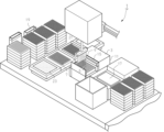
- FIG. 1A shows a DNA amplification system operating with a sample transport section.
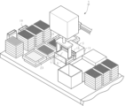
- FIG. 1B shows a DNA amplification system with the inner lid covered.
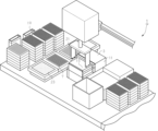
- FIG. 1C shows a DNA amplification system with a movable lid in a heatable state.
- FIG. 2 is a block diagram for explaining the processor.
- FIG. 3 is a flow chart for explaining a method for amplifying DNA using PCR.
- FIG. 4 is a conceptual diagram for explaining the number of PCR cycles for each DNA sample contained in each well of the first multi-well.
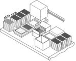
- FIG. 5A is a conceptual diagram showing the state in which the inner lid is lifted.
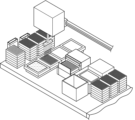
- FIG. 5B is a conceptual diagram illustrating recovery of the target DNA sample after the PCR cycles.
- FIG. 5A is a conceptual diagram showing the state in which the inner lid is lifted.
- FIG. 5B is a conceptual diagram illustrating recovery of the target DNA sample after the PCR cycles.
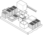
- FIG. 5C is a schematic diagram showing how the collected DNA samples are transferred to corresponding wells of a second multi-well plate.
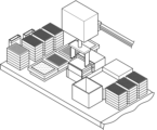
- FIG. 5D is a conceptual diagram showing the inner lid being transferred onto a thermal cycler.
- FIG. 5E is a conceptual diagram showing the inner lid being transferred onto the thermal cycler.
- FIG. 5F is a conceptual diagram showing a state in which the movable cover is in a heatable state.
- FIG. 6 is a photograph, instead of a drawing, showing a microchannel electrophoretic image in Example 2.
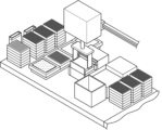
- FIG. 1 is a diagram for explaining a DNA amplification system.
- FIG. 1A shows the specimen transport section in operation.
- FIG. 1B shows the inner lid in a covered state.
- FIG. 1C shows the movable lid in a heatable state.
- This system 1 relates to a DNA amplification system using a PCR device 3.
- This DNA amplification system 1 includes a PCR device 3.
- the PCR device 3 includes a first multi-well 5, a second multi-well 7, a specimen transport section 9, a thermal cycler 11, and a processor 13.
- Each well of the second multi-well 7 preferably corresponds to each well of the first multi-well 5.
- This system 1 preferably further includes a movable lid 15 and an inner lid 17.
- This system 1 may include an oil supply section 19 and a reaction liquid supply section 21.
- This system 1 may be connected to a PCR cycle number determination device that determines the number of PCR cycles for each DNA sample.
- the PCR cycle number determination device may be connected to a concentration analysis device that analyzes the concentration of the sample.
- An example of a PCR cycle number determination device is one that can receive the concentration of the sample and determine the number of PCR cycles for each sample.
- This system 1 can receive PCR information, such as the number of PCR cycles for each DNA sample, from the PCR cycle number determination device.
- the PCR device is a device for amplifying DNA using the polymerase chain reaction.
- PCR devices are publicly known, for example, as described in Japanese Patent No. 7038221.
- the PCR device 3 of the present invention preferably has specifications that allow it to constitute the system 1.
- the PCR device 3 of the present invention is a device for carrying out the DNA amplification method of the present invention, and includes a first multi-well, a second multi-well, a sample transport unit, a thermal cycler, and a processor.
- a multiwell includes two or more wells.
- a multiwell may be a plate including two or more wells (multiwell plate).
- Multiwell plates are a standard format for processing and analyzing multiple samples, and can be of various formats, sizes, and shapes, but are usually made in a standard size and shape and have a standard arrangement of wells. Examples of well arrangements include a 6-well plate (3 ⁇ 2 array of wells), a 12-well plate (4 ⁇ 3 array of wells), a 24-well plate (6 ⁇ 4 array of wells), a 48-well plate (8 ⁇ 6 array of wells), a 96-well plate (12 ⁇ 8 array of wells), and a 384-well plate (24 ⁇ 16 array of wells).
- the multiwell of the present invention is not particularly limited as long as it can be used for PCR, and is not limited to the above multiwell plate.
- the number of wells is preferably 2 to 1000, and more preferably 6 to 500.
- a 48-well plate or a 96-well plate can be preferably used.
- the first multi-well 5 is usually subjected to PCR processing using a thermal cycler while containing a sample.
- Each of the wells 5a, 5b, and 5c of the first multi-well 5 can contain a DNA sample. It is not necessary to perform PCR processing while containing a DNA sample in all wells included in the first multi-well 5.
- the DNA sample used in the present invention contains at least one type of DNA, and preferably contains multiple types of DNA.
- the amount of DNA contained is not particularly limited as long as it is an amount that can be amplified by PCR.
- each well may contain samples in which the same DNA sample has been dispensed, it is preferable that each well contains a different DNA sample. However, this does not exclude the case where some wells contain samples in which the same DNA sample has been dispensed.
- “different DNA samples” means that the samples are not samples in which the same DNA sample has been dispensed.
- the lower limit of the number of types of DNA samples is preferably 2 or more, and may be 10 or more, 20 or more, 30 or more, or 40 or more.
- the upper limit of the number of types of DNA samples is not particularly limited, and may be a number that the PCR device can handle, and may be 1000 or less, 500 or less, 200 or less, or 100 or less.
- the number of types of DNA samples is preferably within the number of wells of the selected multi-well plate.
- the liquid volume of the DNA sample used in the present invention may be an amount that can be amplified by PCR, and can be appropriately determined according to the volume of the well. Although not limited, in the case of a 96-well multi-well plate, it may be 20 ⁇ l to 100 ⁇ l. Meanwhile, a method of screening random peptide libraries is widely used to obtain peptide molecules that bind to specific targets.
- various in vitro display methods such as ribosome display and mRNA display, which use cell-free translation systems, are excellent in that they can construct and screen highly diverse libraries in a short period of time in a single tube.
- the in vitro display method refers to a system that displays a phenotype on a genotype by linking the phenotype and the genotype that codes for the sequence of the phenotype with a non-covalent or covalent bond, and enables the enrichment and amplification (selection) of active species using a replication system reconstructed in a test tube.
- In vitro display methods include ribosome display, mRNA display (WO98/31700), cDNA display, photocrosslinking cDNA display (WO2016/159211), TRAP (transcription-translation coupled with association of puromycin linker) display (T. Ishizuka et al., Am. Chem. Soc. 2013, 135, 14, 5433-5440), cDNA TRAP display (T. Kondo et al., al., Chem. Commun., 2021, 572416-2419), and the RAPID display method (WO2011/049157).
- Step 1 A step of generating a random peptide library with a nucleic acid tag
- Step 2 A step of selecting peptides that interact with a target substance from the random peptide library
- Step 3 A step of amplifying the nucleic acid recovered from the selection step to a predetermined concentration (PCR step).
- step 1 basically, a DNA population (random DNA library) is first prepared, an RNA population (random RNA library) is obtained as an in vitro transcription product, and a peptide population (random peptide library) is obtained as an in vitro translation product.
- step 2 peptides having desired functions and properties are selected from this peptide library using some screening system.
- a magnetic carrier on which a target protein is immobilized is brought into contact with a peptide population, and a mixture of peptide molecules bound to the carrier can be collected using a recovery magnet.
- a peptide population can be poured into a column on which a target protein is immobilized, and a mixture of peptide molecules bound to the column can be collected.
- a nucleic acid molecule that is a template for each peptide molecule is added like a tag by in vitro display technology.
- mRNA is added to each peptide molecule. Therefore, the collected peptide-mRNA complex population is converted back to DNA using reverse transcriptase, and then subjected to step 3.
- a reverse transcription reaction can be performed before selection in order to make the nucleic acid portion into a double-stranded (DNA/RNA hybrid).
- the DNA thus recovered is amplified by PCR to obtain a biased library that is enriched for clones having the desired phenotype.
- the proportion of peptides with the desired function in the peptide library can be increased and concentrated, and the desired peptide can finally be obtained.
- the different DNA sample may be a sample containing the "nucleic acid recovered from the selecting step" in step 3.
- the different DNA sample may be a sample containing DNA encoding the peptide selected in step 2, in other words, the peptide selected from a random peptide library as one that interacts with a target substance.
- DNA obtained by reverse transcription of the mRNA can be used as the DNA sample. That is, an example of the DNA sample is DNA encoding a peptide recovered in the selection step of the mRNA display method. Another example of the DNA sample is a DNA sample recovered from a peptide having a DNA tag. An example of such a DNA sample is a DNA sample recovered in the selection step of various in vitro display methods.
- the DNA samples containing DNA tags recovered by the above method usually have different concentrations. By using the method described in this specification, such multiple types of DNA samples can be amplified to the same concentration.
- the DNA sample contains a fixed base sequence for the 5'-end nucleic acid and the 3'-end nucleic acid of the sense strand of DNA.
- the 5'-end nucleic acid and the 3'-end nucleic acid of the antisense strand also contain a fixed base sequence.
- each of the wells 5a, 5b, and 5c of the first multi-well 5 contains multiple types of DNA samples, and it is preferable that the 5'-end base sequence and the 3'-end base sequence are common.
- the DNA samples obtained by in vitro display using a random library using nucleic acid tags have a common 5'-end nucleic acid and a common 3'-end nucleic acid for each DNA sample contained in one well.
- the 5'-end nucleic acid of the multiple DNA samples is the same, and the 3'-end nucleic acid of the multiple DNA samples is the same.
- the nucleic acid in the intermediate region between the 5'-end base and the 3'-end base has a randomized nucleic acid that is different depending on the DNA sample. Even in this case, the 5'-end and 3'-end base sequences may be different if the wells are different.
- nucleic acid at the 5' end of the sense strand of DNA is, but is not limited to, a nucleic acid having a promoter sequence for transcription, such as a T7 promoter sequence.
- transcription of DNA can be performed in the next step after PCR.
- An example of a nucleic acid at the 3' end of the sense strand of DNA is a nucleic acid encoding a linker that connects puromycin and the peptide to be selected. Note that, as an alternative to puromycin, a substance that inhibits the translation process and can bind nucleic acids and peptides, similar to puromycin, may be used.
- Randomization is a term used to describe a segment of nucleic acid that has, in principle, any possible sequence over a given length.
- the randomized sequence may be of various lengths, ranging from, but not limited to, 3 to 60 nucleotides.
- the chemical or enzymatic reaction by which the random sequence segment is produced may not produce a mathematically random sequence due to possible unknown bias or nucleotide selection.
- Various in vitro displays using random peptide libraries with nucleic acid tags are systems in which random peptide libraries are constructed from various peptides encoded by randomized base sequences, and the peptides of interest are selected by binding these to target proteins. Therefore, in an embodiment in which the method of the present invention is used in an in vitro display using a random library with nucleic acid tags, it is preferable that the DNA sample contains a wide variety of DNAs having the above-mentioned configuration.
- the step of selecting peptides that bind to the target protein from the peptide library and the PCR step of the present invention can be preferably performed in wells at the same position in a multi-well plate.
- the collected samples are preferably discharged into wells in a new multiwell plate of the same type as the multiwell plate used for PCR, at positions corresponding to the wells before collection.
- the first multi-well 5 preferably contains a plurality of different DNA samples.
- the plurality of different DNA samples may not be treated to make the concentrations of the respective DNA samples uniform.
- the second multiwell 7 is similar to the first multiwell 5.
- the wells 7a, 7b, and 7c of the second multiwell 7 correspond to the wells 5a, 5b, and 5c of the first multiwell 5.
- the positions of the corresponding wells 7a, 7b, and 7c in the second multiwell 7 may be A1, A2, and B2.
- These positions correspond to the positions of lattice points (x, y) when the positions of the wells are regarded as lattice points.
- the second multi-well 7 is preferably mounted on a collected specimen mounting section that mounts the second multi-well.
- the collected specimen mounting section preferably has a cooling element for cooling the second multi-well 7, which is a plate.
- the cooling element is preferably connected to a processor.
- the cooling element can cool the second multi-well 7 mounted on the collected specimen mounting section by adjusting the temperature based on instructions from the processor. Examples of such cooling elements include a cooling mechanism that uses a circulator or a Peltier element.
- the specimen transport unit 9 is used to inject a specimen into a well and recover the specimen from the well.
- the specimen transport unit 9 includes a tube such as a pipette (micropipette), a transport mechanism for transporting the tube, and an aspiration and discharge mechanism for adjusting the air in the tube to aspirate and discharge the specimen.
- the transport mechanism of the specimen transport unit 9 changes the position (planar position and height) of the tube upon receiving a command from the processor.
- the aspiration and discharge mechanism aspirates and discharges the specimen at a predetermined position upon receiving a command from the processor. It is preferable that the amount of the specimen aspirated and the amount of the specimen discharged can be adjusted according to a command from the processor.
- the specimen transport unit 9 preferably has a plurality of micropipettes.
- the specimen transport unit for injecting a specimen into a well and the specimen transport unit for recovering a specimen from the well may be the same or different.
- the micropipette of the specimen transport unit is designed to automatically replace the tip.
- the thermal cycler 11 is a temperature control mechanism for PCR.
- the first multi-well 5 is mounted on a plate mounting portion of the thermal cycler 11.
- the thermal cycler 11 can adjust the temperature of the temperature control portion based on instructions from the processor, thereby controlling the temperature of the first multi-well 5.
- the processor 13 is an element for issuing commands to various elements in the PCR device 3.
- FIG. 2 is a block diagram for explaining the processor.
- the processor 13 has an input unit 31, an output unit 33, a control unit 35, a calculation unit 37, and a storage unit 39, and each element is connected by a bus 41 or the like so as to be able to exchange information.
- the storage unit may store a program or various information.
- the processor 13 reads out a program and performs various calculations and processing. In other words, the processing performed by the processor 13 may be based on a program.
- the processor 13 may also include various circuits such as a calculation circuit. When a specific piece of information is input from the input unit, the control unit reads out a program stored in the storage unit.
- control unit appropriately reads out the information stored in the storage unit and transmits it to the calculation unit. Also, the control unit appropriately transmits the input information to the calculation unit.
- the calculation unit performs calculation processing using the various pieces of information received and stores it in the storage unit.
- the control unit reads out the calculation results stored in the storage unit and outputs them from the output unit. In this manner, various processes and steps are executed.
- the various processes are executed by each part or each means.
- the computer may realize various functions and various processes.
- the computer may be standalone. Some of the functions of the computer may be distributed to a server and a terminal. In that case, it is preferable that the server and the terminal are capable of transmitting and receiving information via a network such as the Internet or an intranet.
- the processor may include a trained model that has undergone various machine learning.
- the accuracy of the trained model and the machine learning can be improved by inputting predetermined teacher data into the trained model.
- a predetermined output can be obtained by inputting various data into the trained model. Examples of various data include PCR processing information and various information required to calculate DNA concentration.
- the PCR processing information is input to the processor 13.
- the PCR processing information includes information regarding the number of PCR cycles for each DNA sample contained in each well 5a, 5b, 5c of the first multi-well 5. It is preferable that the PCR processing information also includes position information for each well 5a, 5b, 5c.
- the input PCR processing information is appropriately stored in the storage unit and used in the PCR process. Various information required to calculate the DNA concentration, which will be described later, may also be input to the processor 13.
- the movable lid 15 can be in a heatable state in which the first multi-well 5 is covered and can be heated, and can be moved from the heatable state to a non-heatable state in which the first multi-well 5 is not covered.
- the movable lid 15 is one element of the thermal cycler 11, and preferably includes a heating element so that the first multi-well 5 can be heated.
- the movable lid 15 preferably includes a movable lid body including a heating element and a driving unit such as an actuator for moving the movable lid body.
- the heating element and the driving unit are preferably connected to the processor 13. The heating element can adjust the temperature based on a command from the processor 13.
- the driving unit can change the position of the movable lid 15 based on a command from the processor 13.
- the movable lid 15 includes a heating element.
- the mounting unit on which the first multi-well 5 is mounted may include the heating element of the thermal cycler 11.
- An example of the heating element is a heating wire (resistance wire), and the heating wire may be laid so as to extend over the area of the movable lid 15 that will cover the well.
- the inner lid 17 can be in a covering state in which it covers the first multi-well 5.
- the inner lid 17 is preferably independent of the thermal cycler 11 and can be freely moved.
- the inner lid 17 can be in an open state in which it does not cover the first multi-well 5 by moving the inner lid 17 from a covering state.
- the inner lid 17 is present between the movable lid 15 and the first multi-well 5 when the movable lid 15 is in a heatable state and the inner lid 17 is in a covering state. It is preferable that the inner lid 17 can seal the first multi-well 5 when the inner lid 17 is in a covering state.
- the position of the inner lid 17 can be changed by an actuator such as an inner lid transfer mechanism (also called a handling unit).
- the inner lid transfer mechanism is connected to a processor, for example.
- An example of the inner lid transfer mechanism is a robot arm having a gripper.
- the inner lid transport mechanism upon receiving a command from the processor 13, uses the gripper to grip the inner lid 17, changes the position of the gripped inner lid 17, and releases the gripper, thereby placing the inner lid 17 in a predetermined location.
- the presence of the inner lid 17 allows the first multi-well 5 to be placed in a covered state, thereby preventing the liquid in each well from evaporating during the PCR process. Furthermore, the use of the inner lid 17 can prevent contamination between the wells.
- the inner lid 17 is preferably made of a material with high thermal conductivity. Examples of materials for the inner lid 17 include silicon, rubber, and polystyrene.
- the inner lid 17 is capable of automatically sealing the first multi-well 5 under the control of the processor and maintaining a sealed state even during PCR processing, and is preferably made of resin (an auto-sealing polymer lid).
- the auto-sealing polymer lid helps to minimize evaporation of reagents during long incubation periods.
- the inner lid 17 may be a sticker that can be attached to the multi-well plate. It is preferable that the sticker can be attached with a sealer and peeled off with a peeler.
- the oil supply unit 19 is an element for supplying oil to each well of the first multi-well 5.
- the oil supply unit 19 includes a tube such as a pipette, a transport mechanism for transporting the tube, an aspiration and discharge mechanism for adjusting the air in the tube to suck and discharge it, and an oil source.
- the transport mechanism changes the position of the tube upon receiving a command from the processor.
- the aspiration and discharge mechanism sucks oil from the oil source at a predetermined position upon receiving a command from the processor 13, and discharges the oil. It is preferable that the amount of oil to be sucked and the amount of oil to be discharged can be adjusted according to a command from the processor.
- the oil to be sucked may be held in a container (oil source) capable of holding oil for PCR reaction, for example, and such a container is preferably open at the top so that it can be collected with a pipette or the like.
- oil By using oil, it is possible to prevent evaporation of the liquid when the liquid containing the DNA sample is heated by the PCR process.
- the oil is preferably a non-volatile liquid that is stable at high temperatures, does not affect the PCR reaction, and has a lower specific gravity than the PCR reaction liquid.
- Such oil may be an oil normally used for PCR.
- oils include mineral oil, vegetable oil, animal oil, fluorine-based oil, silicone-based oil, and hydrocarbon-based oil. Among these, mineral oil is preferred.
- the amount of oil to be added is not particularly limited as long as it is an amount that can suppress evaporation of the PCR reaction liquid.
- it may be 5 ⁇ l to 100 ⁇ l.
- the inner cover 17 covers the first multi-well 5 and oil is added to each well, so that evaporation of the liquid (sample and PCR reaction liquid) in each well can be effectively prevented even if the additional PCR and transfer process is repeated.
- the micropipette in the oil supply section is one that can automatically replace the tip.
- the present invention has the movable lid 15 having a heating element and the oil supply unit 19.
- PCR a method of preventing the reaction solution from evaporating and concentrating by adding oil to a tube containing a sample is widely known.
- this method has problems such as the oil cover being inconvenient to handle and the need to leave a part of the sample to prevent oil carryover.
- a lid having a heating element has been developed.
- the use of oil is no longer necessary when using a thermal cycler having a heated lid, and the above problem has been solved.
- the method of the present invention is characterized in that the DNA amplification process repeatedly opens and closes the movable lid 15.
- the inventors have found that, in the method described herein, even if the movable lid of the thermal cycler 11 is repeatedly opened, the PCR step of the present invention can be carried out by using preferably oil or the inner lid 17, more preferably oil and the inner lid 17, in combination with the movable lid 15.
- the reaction liquid supply unit 21 is an element for supplying reaction liquid to each well of the first multi-well 5.
- the reaction liquid supply unit 21 includes a tube such as a pipette, a transport mechanism for transporting the tube, an aspiration and discharge mechanism for adjusting the air in the tube to suck and discharge, and a reaction liquid source.
- the transport mechanism changes the position of the tube upon receiving a command from the processor.
- the aspiration and discharge mechanism sucks reaction liquid from the reaction liquid source and discharges reaction liquid at a predetermined position upon receiving a command from the processor. It is preferable that the amount of reaction liquid to be sucked and the amount of reaction liquid to be discharged can be adjusted according to a command from the processor 13.
- the reaction liquid to be sucked may be held, for example, in a container (reaction liquid source) capable of holding reaction liquid, and such a container is preferably open at the top so that it can be collected with a pipette or the like.
- the reaction liquid preferably contains, for example, a primer for a sequence to be amplified by PCR processing, dNTP (deoxynucleoside triphosphate) which is a substrate for ATGC, and a PCR buffer.
- the reaction liquid preferably contains salts such as MgCl 2 and KCl.
- the components used in the PCR reaction may be included in the DNA sample beforehand, and not included in the reaction solution.
- the forward primer and reverse primer for PCR are preferably annealed to the 5'-end base sequence and the 3'-end base sequence, respectively.
- the length of the primer may be the length normally used in PCR, for example, 20 to 60 bases.
- Such primers can be appropriately designed by those skilled in the art.
- the reaction solution contains at least a heat-resistant DNA polymerase.
- the heat-resistant DNA polymerase a known one used in PCR, such as Taq polymerase, can be preferably used.
- reaction solution supply section is one that can automatically replace the tip.
- Magnetic bead recovery magnet 23 The selected nucleic acid may be purified by a method using magnetic beads and a magnet for recovery, and then eluted in an appropriate solvent before being subjected to the method of the present invention. Furthermore, it is preferable that this series of processes is continuously performed in the same well.
- the next invention relates to a program for amplifying DNA using a PCR device 3.
- This program causes the processor 13 to issue commands to implement various processes, and causes the PCR device 3 to execute the various processes. In other words, this program causes the processor 13 to execute a cycle number input process.
- This program also causes the PCR device 3, via the processor 13, to execute a process of repeating a minimum PCR process, a first transfer process, and an additional PCR/transfer process.
- This invention also relates to a non-transitory information recording medium that stores the above-mentioned program. Examples of non-transitory information recording media are CD-ROMs, DVDs, SD cards, and USB memories.
- the PCR device 3 operates, for example, as follows.
- the number of PCR cycles is input for each DNA sample contained in each well of the first multi-well 5 of the PCR device 3 .
- the processor 13 then drives the thermal cycler 11 in which the first multi-well 5 is mounted, causing the PCR device to carry out PCR for the minimum number of cycles, which is the smallest number of cycles input in the cycle number input step.
- the processor 13 uses the sample transport unit 9 to transport the sample for which the minimum number of cycles was set in the cycle number input step and for which PCR has been performed for the minimum number of cycles to the second multi-well 7 .
- the processor 13 drives the thermal cycler 11 equipped with the first multi-well 5 to perform further PCR up to the maximum number of cycles, which is the largest number of cycles input in the cycle number input step, and also repeats an additional PCR/transport step in which the sample that has reached the number of cycles input in the cycle input step is transported to the second multi-well 7 using the sample transport unit 9. This operation will be described in detail in the following method for amplifying DNA using PCR.
- FIG. 3 is a flow chart for explaining the method for amplifying DNA using PCR.
- Fig. 3(a) shows the overall flow
- Fig. 3(b) shows the minimum PCR step (S102).
- the method for amplifying DNA using PCR includes a cycle number acquisition step (S101), a minimum PCR step (S102), a first transfer step (S103), and a step of repeating the additional PCR and transfer steps (S104).
- the cycle number acquisition step is a step for acquiring the number of PCR cycles for each DNA sample contained in each well of the first multi-well 5.
- the number of PCR cycles for each DNA sample contained in each well of the first multi-well 5 is input to the system 1. In this manner, the system 1 can obtain the number of PCR cycles for each DNA sample contained in each well of the first multi-well 5.
- This step may include a PCR cycle number determination step.
- the PCR cycle number determination step is a step for determining the number of PCR cycles for each DNA sample contained in each well of the first multi-well 5. In other words, this step is a step for determining the number of cycles to perform PCR for each well so that the concentrations of the DNA samples contained in all wells of the first multi-well 5 are within a certain range.
- the PCR cycle number determination device determines the number of PCR cycles for each DNA sample contained in each well of the first multi-well 5.
- An example of the cycle number acquisition process is to use the DNA concentration of each DNA sample contained in the well to obtain a PCR cycle number that will result in a certain range of DNA concentration after amplification.
- the DNA concentration can be determined by any known method.
- the DNA concentration can be determined by using the quantitative PCR method (qPCR method).
- the PCR cycle number determination device for example, operates a liquid transport device such as a micropipette based on a command from the processor to extract a portion of each DNA sample contained in each well of the first multi-well 5.
- the PCR cycle number determination device discharges a portion of the extracted DNA sample to a concentration measurement device based on the quantitative PCR method (qPCR method) and determines the DNA concentration based on the quantitative PCR method (qPCR method).
- the PCR cycle number determination device causes the processor to read information required to determine the PCR cycle number stored in the memory unit and perform a calculation to determine the PCR cycle number using the DNA concentration.
- information required to determine the number of PCR cycles is information storing the relationship between the range of values of DNA concentration and the number of PCR cycles. For example, when the concentration of DNA is within a predetermined concentration range, the number of PCR cycles is a predetermined number.
- the number of PCR cycles for each DNA sample contained in each well of the first multi-well 5 thus determined is appropriately stored in the storage unit.
- the processor may output information regarding the number of PCR cycles stored by the PCR cycle number determination device to the system 1 or the PCR device 3 of the system 1.
- the system 1 and the PCR cycle number determination device may share a processor.
- This method can be preferably used for mRNA display or RAPID display using a random peptide library using DNA tags.
- qPCR method quantitative PCR method
- the PCR device 3 performing the cycle number acquisition step (S101), the minimum PCR step (S102), the first transfer step (S103), and the step of repeating the additional PCR and transfer steps (S104) may be the same as or different from the PCR device for performing the quantitative PCR method. If these devices are different, the control unit or processor of the PCR device used to perform the quantitative PCR method can output PCR information and the DNA concentration of each sample to the control unit or processor of PCR device 3 or system 1.
- the number of PCR cycles for each well may be determined by determining the target DNA concentration after amplification and calculating the PCR amplification efficiency from the DNA concentration of the DNA sample contained in each well.
- the PCR amplification efficiency and the target DNA concentration (or the target DNA concentration range) are stored in the memory unit of the processor.
- the PCR cycle number determination device reads out the DNA concentration, PCR amplification efficiency, and DNA concentration (or the target DNA concentration range) of the DNA sample contained in each well based on the instructions of the program, for example, and causes the calculation unit to perform a calculation to determine the number of PCR cycles. In this way, the PCR cycle number determination device can determine the number of PCR cycles for each well.
- the processor may determine the amount of PCR product based on the instructions of the program, read the amount of PCR product that reaches the plateau from the memory unit, compare them, and perform a calculation to divide the number of PCR cycles once if the amount of PCR product exceeds the amount that reaches the plateau.
- the target DNA concentration is preferably the same for multiple DNA samples with different concentrations.
- the target DNA concentration may be appropriately adjusted depending on the intended use of the amplified DNA sample, and may be, for example, between 3.0 ⁇ 10 8 and 1.6 ⁇ 10 13 molecules/uL, 1.0 ⁇ 10 9 to 1.0 ⁇ 10 12 molecules/uL, or 1.0 ⁇ 10 11 to 1.6 ⁇ 10 11 molecules/uL.
- the PCR cycle number may be a numerical value obtained by adding or subtracting an appropriate value to the Cq (quantification cycle) value (also called the Ct (threshold cycle) value) obtained when the DNA concentration of a sample is measured by the qPCR method.
- the appropriate value can be appropriately determined based on the target DNA concentration and the results of preliminary experiments using a PCR device that performs quantitative PCR and a PCR device that is used in the amplification process. Examples of appropriate values may be -2, -1, 0, 1, 2, 3, or 4.
- the PCR cycle number determination device may, for example, perform a calculation to determine the Cq value or Ct value based on the instructions of the program, read a correction value (the appropriate value described above) from the memory unit, perform a calculation to add (or subtract) the correction value to (or from) the Cq value or Ct value, and store it in the memory unit as the PCR cycle number for each sample.
- the DNA concentration of the DNA sample can be determined by measuring the absorbance using a spectrophotometer.
- the PCR cycle number determination device operates a liquid transport device such as a micropipette based on a command from a processor to extract a portion of each DNA sample contained in each well of the first multi-well 5. Then, for example, the PCR cycle number determination device ejects a portion of the extracted DNA sample into the measurement section of the spectrophotometer based on a command from the processor.
- the PCR cycle number determination device for example, operates a spectrophotometer based on a command from the processor to measure the absorbance of each DNA sample contained in the measurement section.
- the measured absorbance is stored in the memory section of the processor.
- the PCR cycle number determination device reads information required to determine the DNA concentration from the memory section based on a command from a program, and causes the processor's calculation section to perform a calculation to determine the DNA concentration using the absorbance.
- the determined DNA concentration is stored in the memory section. In this way, the PCR cycle number determination device can determine the DNA concentration of each DNA sample contained in each well of the first multi-well 5. After determining the DNA concentration, the number of PCR cycles can be calculated and output in the same manner as described above.
- the PCR cycle number input step determines the number of PCR cycles for each DNA sample contained in each well of the first multi-well 5.
- the processor may store the determined number of PCR cycles for each DNA sample (hence, the number of PCR cycles for each well) in a storage unit or output it to the processor of the PCR device. In this manner, the number of PCR cycles for each DNA sample is input to the system 1.
- FIG. 4 is a conceptual diagram for explaining the number of PCR cycles for each DNA sample contained in each well of the first multi-well.
- a number of PCR cycles is assigned to each well.
- wells with cycle numbers of 5, 6, and 7 are depicted.
- the concentration of each DNA sample is determined, the number of PCR cycles for each DNA sample (and therefore each well) is determined in a PCR cycle number determination process.
- the determined number of PCR cycles is input to system 1 in a PCR cycle number input process together with the position information of each sample.
- FIG. 4(a) A conceptual diagram of each DNA sample and the number of PCR cycles is as shown in FIG. 4(a).
- the minimum PCR step is a step of performing PCR for the minimum number of cycles (n min ), which is the smallest number of cycles obtained in the cycle number acquisition step. Each step of each PCR cycle is as shown in FIG. .
- the selected nucleic acid may be purified by a method using magnetic beads or the like, eluted in an appropriate solvent, and then subjected to PCR processing.
- the cycle number acquisition step (S101) described above may be performed after the purification step.
- the oil supply unit 19 supplies oil to each well of the first multi-well 5 (oil supply step). Based on a command from the processor 13, the oil supply unit 19 moves the transfer mechanism to the oil source and uses the suction and discharge mechanism to draw the oil into the tube. Based on a command from the processor 13, the oil supply unit 19 moves the tube to above each well or inserts the tube into each well and uses the suction and discharge mechanism to discharge the oil into each well. In this way, the oil supply unit 19 can supply oil to each well of the first multi-well 5.
- the reaction liquid supply unit 21 supplies reaction liquid to each well of the first multi-well 5 (reaction liquid supply step).
- reaction liquid supply step When supplying this reaction liquid, it is preferable to pre-incubate the DNA sample using the thermal cycler 11 and then supply the reaction liquid.
- the reaction liquid supply unit 21 moves the transport mechanism to the reaction liquid source and uses the suction and discharge mechanism to suction the reaction liquid into the tube.
- the reaction liquid supply unit 21 moves the tube to above each well or inserts the tube into each well and uses the suction and discharge mechanism to discharge the reaction liquid into each well. In this way, the reaction liquid supply unit 21 can supply reaction liquid to each well of the first multi-well 5. If the DNA sample contains reaction liquid, the reaction liquid supply step may not be necessary.
- the oil supplying process and the reaction liquid supplying process are optional processes. When the oil supplying process and the reaction liquid supplying process are performed, either one can be performed first. However, when both the oil supplying process and the reaction liquid supplying process are performed, it is better to perform the oil supplying process first.
- the first multi-well 5 may be transferred to a predetermined position in the thermal cycler 11.
- Inner lid covering step In the minimum PCR step, it is preferable to put the inner lid 17 in a covered state (inner lid covering step).
- the inner lid transport mechanism grasps the inner lid 17 using the grasping part, changes the position of the grasped inner lid 17, and releases the grasping part to place the inner lid 17 on top of the first multi-well 5. Since the inner lid 17 can be made to cover the first multi-well 5, it is possible to prevent the liquid in each well from evaporating in the PCR processing step.
- the movable lid 15 of the thermal cycler 11 In the minimum PCR step, it is preferable to put the movable lid 15 of the thermal cycler 11 into a heatable state after the inner lid 17 is put into a covered state (movable lid covering step).
- the driving unit changes the position of the movable lid 15 to the top of the first multi-well 5 (thus, above the inner lid 17 if it exists) based on a command from the processor 13. In this way, the thermal cycler 11 can prepare for PCR.
- the heating element controls the temperature based on a command from the processor 13, thereby changing the temperature of the sample in each well of the first multi-well 5.
- the temperature treatment time of the heating element can also be controlled by reading the PCR information stored in the memory unit of the processor and processing the heating element.
- the minimum PCR step is a step of performing PCR for the minimum number of cycles (n min ), which is the smallest number of cycles obtained in the cycle number acquisition step. That is, in this step, PCR cycles are performed n min times.
- the PCR (polymerase chain reaction) cycles may be the same as PCR cycles that are usually performed.
- Each PCR cycle usually includes the following three steps (PCR step). By repeating this cycle, the target nucleic acid in the sample can be amplified.
- Step 1 DNA denaturation by heat treatment (dissociation reaction from double-stranded DNA to single-stranded DNA) Typically, the sample is heated to about 95°C.
- Step 2 Annealing of primer to template single stranded DNA Typically, samples are heated to about 55 to 65°C.
- Step 3 Extending the primer with a DNA polymerase Typically, samples are heated to about 72°C.
- the temperature and processing time of each step may be appropriately adjusted using a known method.
- the PCR process is not limited to the above three-step PCR method, and known PCR methods such as a two-step PCR method may be used.
- the minimum PCR process is completed by performing the PCR cycle n min times. For example, if n min is 5, the PCR process is performed 5 cycles.
- a reagent that stops PCR may be added to the well containing the DNA sample that has the minimum number of cycles in the cycle number acquisition process. This also applies below.
- the reagent that stops PCR may be a known PCR inhibitor (e.g., EDTA).
- the process of adding the reagent that stops PCR may be performed in the same manner as the process of adding the reaction solution.
- the first transfer step is a step for transferring a DNA sample, which is a sample that has been determined to have the minimum number of cycles in the cycle number acquisition step and has undergone PCR for the minimum number of cycles, to the second multiwell 7.
- a DNA sample which is a sample that has been determined to have the minimum number of cycles in the cycle number acquisition step and has undergone PCR for the minimum number of cycles
- the DNA sample to be transferred is transferred to a well of the second multiwell 7 that corresponds to the well of the first multiwell 5.
- the second multiwell 7 is left stationary under cooling.
- the movable lid 15 and inner lid 17 are used in the PCR process, it is preferable that the movable lid 15 is in a state that does not require heating and the inner lid 17 is in an open state in the first transfer step.
- the driving unit changes the position of the movable lid 15 from the top of the first multi-well 5 to the initial position based on a command from the processor.
- An example of the initial position is inside the thermal cycler 11.
- the top of the thermal cycler 11 is in an open state. In this way, the thermal cycler can put the movable lid 15 in a state where heating is not required (movable lid initializing step).
- the movable lid 15 has a heating element.
- the inner lid transport mechanism receives a command from the processor 13, uses the gripper to grip the inner lid 17 located above the first microwell 5, changes the position of the gripped inner lid 17 to the inner lid initial position, and releases the gripper, thereby placing the inner lid 17 in the inner lid initial position. In this way, the inner lid transport mechanism can place the inner lid 17 in an open state.
- an automatic dispenser can be used as one aspect of the transfer mechanism of the sample transport section 9, but the function of an automatic dispenser is usually intended to perform tasks such as adding different amounts of liquid to each well, or sucking up different amounts of liquid and recovering them in another multi-well plate, and is not intended to repeat the process of extracting and recovering some samples with no regularity in their arrangement from a single plate, then performing another operation and then performing further recovery.
- the processor 13 stores position information of the wells in the first multi-well 5 in which PCR is performed for the minimum number of cycles (n min ) and position information of the wells in the second multi-well 7 corresponding thereto.
- the transport mechanism of the specimen transport unit 9 receives a command from the processor and moves the position of a tube to the well in the first multi-well 5 in which PCR is performed for the minimum number of cycles (n min ).
- the suction and discharge mechanism of the specimen transport unit 9 receives a command from the processor 13 and aspirates the specimen in the well in which PCR is performed for the minimum number of cycles (n min ).
- the transport mechanism of the specimen transport unit 9 receives a command from the processor 13 and moves the position of a tube to above the well in the second multi-well 7 corresponding to the well in which PCR is performed for the minimum number of cycles (n min ).
- the transport mechanism of the specimen transport unit 9 may insert a tube into the well.
- the suction and discharge mechanism of the specimen transport unit 9 receives a command from the processor 13 and discharges the specimen into the well in the second multi-well 7. In this way, the system 1 can transfer the specimen to be transferred in the first transfer step from the well of the first multi-well 5 to the well of the second multi-well 7 corresponding to the well of the first multi-well 5.
- the suction and discharge mechanism of the specimen transport unit 9 is controlled in response to a command from the processor 13 to suck the liquid in the well with a suction force sufficient to suck the liquid containing the DNA specimen in the well without sucking the oil. In this way, it is possible to suck up components other than oil.
- the transport mechanism of the specimen transport unit 9 is controlled in response to a command from the processor 13 to move the position of the tube to a predetermined position (predetermined altitude position) inside the well in which the minimum number of cycles (n min ) of PCR is performed among the multiple wells of the first multi-well 5.
- Figure 4(b) shows the DNA sample contained in the well with the PCR cycle number of 5 being transferred to the corresponding well of the second multi-well at the cycle number 5 location.
- the step of repeating the additional PCR and transfer steps is a step of repeating a step of further performing PCR after the first transfer step up to the maximum number of cycles, which is the highest number of cycles acquired in the cycle number acquisition step, and transferring the sample that has reached the number of cycles acquired in the cycle number acquisition step to the second multi-well 7.
- the temperature and processing time of each step of the PCR cycle can be appropriately adjusted based on a known method, but the same conditions as those of the minimum PCR step are preferable.
- the system 1 may perform the PCR step once after the first transport step, or the system 1 may perform the inner lid covering step and the movable lid covering step, and then perform the PCR step once.
- the processor 13 causes the system 1 to perform the (n min +2)th PCR.
- the processor 13 reads the PCR information from the storage unit and performs a calculation to determine whether there is a (n min +1) number of PCR cycles, and if there is no (n min +1) number, outputs a command to the system 1 to perform the (n min +2)th PCR.
- the second transfer step is performed.
- the system 1 may perform the second transfer step after performing the initial positioning step of the movable lid 15 and the opening step of the inner lid 17.
- the processor 13 stores the position information of the wells in the first multi-well 5 in which the (n min +1) cycle of PCR is performed and the position information of the corresponding wells in the second multi-well 7. Therefore, the processor 13 can use the system 1 to transfer the DNA sample contained in the well in which the (n min +1) cycle of PCR is performed, among the multiple wells in the first multi-well 5, to the corresponding wells in the second multi-well 7.
- the processing at this time is similar to that of the first transfer step.
- the maximum number of cycles which is the maximum number of cycles acquired in the cycle number acquisition step, is defined as (n max ).
- the step of repeating the additional PCR and transport step repeats the above steps after the (n min +1)-th PCR step up to the (n max )-th PCR step. In this way, each well of the second multi-well 7 contains a DNA sample with a DNA concentration within a predetermined range.
- the DNA sample contained in the well with the PCR cycle number of 5 is transferred to the corresponding well of the second multi-well, and then the inner lid covering step and the movable lid covering step are performed, and a PCR cycle is performed. Then, the PCR cycle number is increased by one to 6.
- a well with a PCR cycle number of 6 exists. Therefore, after the sixth cycle of PCR, the movable lid initializing step and the inner lid opening step are performed. Then, the second transfer step is performed for the well with the PCR cycle number of 6.
- the inner lid covering step and the movable lid covering step are performed, and a PCR cycle is performed.
- the PCR cycle number is increased by one to 7.
- a well with a PCR cycle number of 7 exists. Therefore, after the seventh cycle of PCR, the movable lid 15 initializing step and the inner lid 17 opening step are performed. Then, the third transfer step is performed for the well with the PCR cycle number of 7.
- each well of the second multi-well 7 corresponding to each well of the first multi-well 5 contains a DNA sample with a DNA concentration within a predetermined range. Since the method of the present invention includes repeating the additional PCR and transfer steps described above, the thermal cycler is alternately opened and closed.
- the above-mentioned specimen transport unit, oil supply unit, and reaction liquid supply unit may all be different devices, or any two of them, or all of them, may be the same device. Since all of these include a tube such as a pipette (micropipette), a transport mechanism for transporting the tube, and an aspiration and discharge mechanism for adjusting the air inside the tube and aspirating and discharging it, the specimen transport process, oil supply process, and reaction liquid supply process can be performed in the same device by replacing the pipette tip. Switching between each process can be performed appropriately based on instructions from the processor.
- a tube such as a pipette (micropipette)
- a transport mechanism for transporting the tube and an aspiration and discharge mechanism for adjusting the air inside the tube and aspirating and discharging it
- the specimen transport process, oil supply process, and reaction liquid supply process can be performed in the same device by replacing the pipette tip. Switching between each process can be performed appropriately based on instructions from the processor.
- System 1 can amplify the DNA concentration of each sample within a certain range without diluting multiple different DNA samples, it can be ideally used to amplify DNA samples collected in in vitro displays such as mRNA display and RAPID display. This is because amplification can be performed while maintaining the diversity of DNA, allowing a larger number of candidate peptides to be selected in the subsequent selection process.
- a 96-well multiwell plate (Thermo Fisher Scientific) is used as the first and second multiwells.
- the specimen transport unit is a Fluent (registered trademark) Automation WORKSTATION manufactured by TECAN, which has an automatic dispenser and a robot arm.
- the automatic dispenser incorporated in this WORKSTATION has eight independent dispense channels and is capable of dispensing and pipette transport operations.
- this WORKSTATION is also used as an oil supply unit and a reaction solution supply unit. By appropriately replacing the above chips, each function can be performed.
- This WORKSTATION also has 96 fixed dispensing channels, which can be used to supply reaction solutions, such as dispensing to all wells simultaneously.
- the thermal cycler used is an on-deck thermal cycler (ODTC) from Inheco. This thermal cycler has a movable heating lid, and the heating and opening and closing of the lid can be automatically controlled.
- ODTC on-deck thermal cycler
- the T Robot from Jena and the ATC from Thermo Fisher Scientific can also be used.
- An Auto-Sealing PCR Plate Lid (manufactured by AZENTA LIFE SCIENCES) is used as the inner lid.
- an arch-type Auto-Sealing Lid #MSL2022 (manufactured by BIO-RAD) or the like can also be used.
- a 100 ml Trough (manufactured by TECAN) is used as the oil source and the reaction liquid source.
- the above elements are arranged as shown in FIG. 1A.
- the WORKSTATION and thermal cycler are connected to a computer, and the automatic pipetting machine, robot arm, and thermal cycler are controlled in a coordinated manner by software (FluentControl TM ) stored in the computer.
- the computer stores a program capable of implementing the method of the present invention, and each of the above elements is made to operate in accordance with the program.
- LightCycler registered trademark
- 96 manufactured by Roche Diagnostics
- DNA can be amplified as follows.
- a random DNA library is prepared having a T7 promoter sequence at the 5' end of the sense strand of DNA, a nucleic acid encoding an annealing site of a linker connecting puromycin and a peptide to be selected at the 3' end, and a DNA sequence having 30 to 45 randomized nucleotides between them.
- a random peptide library is prepared in which each peptide has a DNA/RNA heteroduplex nucleic acid tag according to the TRAP display method (WO2014/119600).
- Each of the prepared random peptide libraries is poured into a multiwell plate in which magnetic beads having a desired target protein immobilized thereon are placed in each well, and the peptides with nucleic acid tags bound to the magnetic beads are collected with a magnet.
- the nucleic acid encoding the sequence of the peptide bound to the target protein is added to 50 ⁇ l of the PCR reaction solution, treated at 94° C., and collected in a new multi-well plate (first multi-well), and used as each DNA sample to be subjected to the PCR process described in this patent.
- the PCR reaction solution used at this time contains a final concentration of 0.25 ⁇ M primer, 0.25 mM dNTP (deoxynucleoside triphosphate) which is a substrate for ATGC, 1 ⁇ PCR buffer, 2 mM MgCl 2 and salts such as KCl, etc.
- the forward primer is a 52-base-long nucleic acid that anneals to the T7 promoter sequence at the 5' end of the DNA
- the reverse primer is a 44-base-long nucleic acid that anneals to the nucleic acid encoding the linker that connects the puromycin at the 3' end of the DNA and the peptide.
- 1 ⁇ l was taken from each DNA sample contained in each well of the multi-well plate, and the concentration of each DNA sample was analyzed using quantitative PCR (qPCR).
- the PCR cycle number for each DNA sample was determined by adding 2 to the obtained Ct value. Note that the above added value was obtained in a preliminary study using a PCR device used for quantitative PCR and a PCR device used for amplification.
- the PCR cycle numbers obtained from the samples this time are assumed to be 5, 6, and 7.
- the number of PCR cycles is input into the computer of the above system, and the program of the present invention is executed.
- the above-mentioned automatic dispenser supplies each well with an appropriate amount of mineral oil stored in the oil source so as to suppress evaporation of the reaction solution.
- the multiwell plate (first multiwell) containing each DNA sample is transferred to the thermal cycler using a robot arm, and the inner lid placed in the inner lid placement area is transferred by the above-mentioned robot arm and placed on the multiwell plate (first multiwell) placed on the thermal cycler to cover it.
- the movable lid is placed in a heatable state so that it can cover and heat the first multiwell, and then pre-incubated at 94°C.
- the Taq polymerase (reaction solution in the present invention) stored in the reaction solution source is supplied to each well by the above-mentioned automatic dispenser so as to have a final concentration of 25 Units/ml.
- PCR is performed for 5 cycles, which is the smallest number of cycles among the PCR cycles for each DNA sample.
- PCR conditions can be appropriately selected, but for example, 94° C. for 40 seconds, 61° C. for 40 seconds, and 72° C. for 40 seconds.
- the movable lid is moved from the top of the first multi-well to its initial position, making it unnecessary to heat the sample.
- the inner lid is then transferred using the robot arm and placed on the inner lid placement area (inner lid initial position).
- the DNA sample with five PCR cycles (cycle number 5 in FIG. 4(b)) is collected by the automatic dispenser, and the multi-well plate (second multi-well) mounted on the collected sample mounting section, which has a cooling mechanism using a circulator, is transferred to the wells corresponding to those of the first multi-well.
- the inner lid placed in the inner lid placement area is transferred by the robot arm and placed on the multi-well plate (first multi-well) placed on the thermal cycler to cover it.
- the movable lid is placed in a heatable state in which it can cover and heat the first multi-well.
- the 6th cycle of PCR is performed.
- the PCR conditions can be selected as appropriate, but may be the same as the conditions for the 5th cycle, for example.
- the position of the movable lid is moved from the top of the first multi-well to the initial position, making it unnecessary to heat the plate.
- the inner lid is sucked and transported using the robot arm and placed in the inner lid storage area.
- the DNA sample with six PCR cycles is collected by the automatic dispenser and transported to the wells of the multi-well plate (second multi-well) that correspond to the wells of the first multi-well.
- the inner lid placed in the inner lid placement area is transferred by the robot arm and placed on the multi-well plate (first multi-well) placed on the thermal cycler to cover it.
- the movable lid is placed in a heatable state so that the first multi-well can be covered and heated. Then, the 7th cycle of PCR is performed.
- the PCR conditions can be selected appropriately, but may be the same as the conditions for the 5th cycle, for example.
- the position of the movable lid is moved from the top of the first multi-well to the initial position, making it unnecessary to heat the plate.
- the inner lid is sucked and transported using the robot arm and placed in the inner lid storage area.
- the DNA sample that has undergone seven PCR cycles is collected by the automatic dispenser and transported to the wells of the multi-well plate (second multi-well) that correspond to the wells of the first multi-well.
- FIG. 5 is a diagram for explaining the operation of the PCR device in the embodiment.
- Fig. 5A is a conceptual diagram showing the state in which the inner lid is lifted. As shown in Fig. 5A, the movable lid of the thermal cycler slides. After that, the robot arm lifts the inner lid and carries it to the inner lid storage area.
- Fig. 5B is a conceptual diagram showing how the target DNA samples are collected after the PCR cycles. As shown in Fig. 5B, an automatic pipetting machine collects the target samples (samples that have reached the desired number of cycles) from the wells of a multi-well plate placed in a thermal cycler. In the example of Fig. 5B, multiple samples are collected at once.
- 5C is a schematic diagram showing the transfer of the collected DNA samples to corresponding wells of a second multi-well plate. As shown in FIG. 5C, the collected samples are dispensed into the corresponding wells of the second multi-well plate.
- Fig. 5D is a schematic diagram showing the inner lid being transferred onto the thermal cycler. As shown in Fig. 5D, after the target sample is collected, the robot arm moves the inner lid from the inner lid placement area to the multi-well plate on the thermal cycler.
- 5E is a conceptual diagram showing the state in which the inner lid is transferred onto the thermal cycler. As shown in FIG 5E, the inner lid is placed on the multi-well plate placed on the thermal cycler.
- FIG. 5F is a conceptual diagram showing the state in which the movable lid is in a heatable state. As shown in Fig. 5F, the movable lid having a heating function of the thermal cycler slides and closes completely, and then the next PCR cycle is started.
- the configuration of the DNA amplification system for providing DNA samples was as follows.
- a 96-well multiwell plate (Thermo Fisher Scientific) was used as the first and second multiwells.
- a Fluent (registered trademark) Automation WORKSTATION manufactured by TECAN Corporation which has an automatic pipetting machine and a robot arm, was used.
- this WORKSTATION was also used as an oil supply section and a reaction solution supply section.
- An 8-channel automatic dispenser was used for oil supply, and a 96-channel automatic dispenser was used for reaction solution supply.
- the thermal cycler used was an On-Deck Thermal Cycler (ODTC) manufactured by Inheco.
- ODTC On-Deck Thermal Cycler
- An Auto-Sealing PCR Plate Lid (manufactured by AZENTA LIFE SCIENCES) was used as the inner lid.
- a 100 ml Trough (manufactured by TECAN) was used as the oil source and the reaction liquid source.
- the above elements were arranged as shown in FIG. 1A.
- the WORKSTATION and thermal cycler were connected to a computer, and the automatic pipetting machine, the robot arm, and the thermal cycler were controlled in conjunction with each other by software (FluentControl TM ) stored in the computer.
- the computer was configured to store a program capable of implementing the method of the present invention, and each of the above elements was configured to operate in accordance with the program.
- LightCycler (registered trademark) 96 manufactured by Roche Diagnostics
- amplification of DNA samples was carried out as follows.
- the DNA shown in SEQ ID NO: 1 was used as a template for PCR amplification.
- Template DNA (SEQ ID NO: 1) with a concentration of about 3 x 10 10 molecular/ul was diluted 6-fold with a PCR reaction solution, and then diluted in 8 steps with a 2-fold common ratio to prepare 8 samples with different concentrations. These were randomly placed in a 96-well multiwell plate (first multiwell) to serve as DNA samples to be subjected to the PCR process.
- the PCR reaction solution used in the quantitative PCR and PCR for amplification below contained 0.25 ⁇ M primers at final concentrations, 0.25 mM dNTP (deoxynucleoside triphosphate) as a substrate for ATGC, 1 x PCR buffer, and 2 mM MgCl 2.
- a nucleic acid (SEQ ID NO: 2) with a base length that anneals to the 5' end of DNA was used as a forward primer
- a nucleic acid (SEQ ID NO: 3) with a base length that anneals to the 3' end of DNA was used as a reverse primer.
- the PCR cycle number thus obtained and the corresponding position information of the wells in which the samples were placed were input into the computer of the above system, and the program of the present invention was executed.
- the above-mentioned automatic dispenser supplied each well with an appropriate amount of mineral oil stored in the oil source so as to suppress evaporation of the reaction solution.
- the multi-well plate (first multi-well) containing each DNA sample was transferred to the thermal cycler using a robot arm, and the inner lid placed in the inner lid placement area was transferred by the above-mentioned robot arm and placed on the multi-well plate (first multi-well) placed on the thermal cycler to cover it.
- the movable lid was placed in a heatable state in which it could cover the first multi-well and heat it, and then pre-incubated at 94°C.
- the Taq polymerase reaction solution in the present invention
- the reaction solution source was supplied to each well by the above-mentioned automatic dispenser so as to have a final concentration of 25 Units/ml.
- Six cycles of PCR which is the smallest number of cycles among the PCR cycles for each DNA sample, were performed.
- the PCR conditions were 94°C for 40 seconds, 61°C for 40 seconds, and 72°C for 40 seconds.
- the movable lid was first moved from the top of the first multi-well to its initial position, making it unnecessary to heat the sample.
- the inner lid was then transferred using the robot arm and placed on the inner lid placement area (inner lid initial position).
- DNA samples with six PCR cycles were collected using an automatic dispenser, and a multi-well plate (second multi-well) mounted on a collected sample mounting section with a cooling mechanism using a circulator was transferred to the wells corresponding to those of the first multi-well.
- the inner lid placed in the inner lid placement area was transferred by the robot arm and placed on the multi-well plate (first multi-well) placed on the thermal cycler to cover it.
- the movable lid was placed in a heatable state in which it could cover and heat the first multi-well.
- the seventh cycle of PCR was performed.
- the PCR conditions were the same as those for the sixth cycle. From the seventh cycle onwards, the same procedure as in the sixth cycle was used to transfer the samples subjected to PCR for each cycle from the multiwell plate (first multiwell) to the multiwell plate (second multiwell), and this was repeated up to the maximum number of cycles, i.e., the 20th cycle.
- FIG. 6 is a photograph in lieu of a drawing showing the microchannel electrophoresis image in Example 2.
- a to H and 1 to 12 in FIG. 6 correspond to A to H and 1 to 12 in Table 1, respectively.
- the DNA to be amplified by PCR is about 106 bp, and the band of the DNA was confirmed at a position of about 106 bp on the image.
- the concentration of all samples was within the range of 8.86 ⁇ 10 9 to 5.27 ⁇ 10 10 molecules/uL. From the above, it was confirmed that the amplification step of the present invention ensures that the DNA concentration of each sample after PCR amplification falls within a certain range for multiple DNA samples with different concentrations.
- This invention can be used in the pharmaceutical and bio-related industries.
Landscapes
- Chemical & Material Sciences (AREA)
- Organic Chemistry (AREA)
- Life Sciences & Earth Sciences (AREA)
- Zoology (AREA)
- Wood Science & Technology (AREA)
- Proteomics, Peptides & Aminoacids (AREA)
- Health & Medical Sciences (AREA)
- Engineering & Computer Science (AREA)
- Chemical Kinetics & Catalysis (AREA)
- Biophysics (AREA)
- Biochemistry (AREA)
- Microbiology (AREA)
- Molecular Biology (AREA)
- Biotechnology (AREA)
- Analytical Chemistry (AREA)
- Physics & Mathematics (AREA)
- Immunology (AREA)
- Bioinformatics & Cheminformatics (AREA)
- General Engineering & Computer Science (AREA)
- General Health & Medical Sciences (AREA)
- Genetics & Genomics (AREA)
- Measuring Or Testing Involving Enzymes Or Micro-Organisms (AREA)
- Apparatus Associated With Microorganisms And Enzymes (AREA)
Abstract
Description
工程1:核酸タグのついたランダムペプチドライブラリーを生成する工程
工程2:ランダムペプチドライブラリーから目的の機能を持つペプチドを選別する工程
工程3:選別する工程から回収された核酸を所定濃度まで増幅する工程(PCR工程)
上記の3工程を繰り返すことにより,ペプチドライブラリー中の目的の機能を持つペプチドの割合を増加・濃縮することができ,最終的に目的とするペプチドを取得することができる。
このような技術に使用できる,複数のDNAサンプルに対するPCR増幅プロセスを正規化するための方法やシステムが提案されている(WO2022/081934号パンフレット)。
通常,PCR工程後は再び上記の工程1に戻る。工程1での操作性を考えた場合,PCR工程後にすべてのサンプルがより近い濃度になっていることが望ましい。これを実現するには工程3のPCR工程で各サンプルに適切なサイクル数のPCRを実施することが望ましい。しかしながら,工程2の選別工程から回収された各サンプルの核酸タグ濃度には,通常大きなばらつきが生じる。そのため,多検体のサンプルの個々に対して適切なPCRサイクルをそれぞれ実施するのは困難である。
この課題に対処するためには,適切なサイクル数が同じ及び/又は類似のサンプルをグループ化して,それぞれのグループにおいてPCRを実施することが考えられる。しかし,少数のPCR装置でこのような作業を実施すると,PCRを繰り返し実施しなければならず効率が悪い。また,これを避けるために多数のPCR装置を準備すると,多額の費用と広い設置場所が必要になる。
この明細書は,複数のDNA検体のDNAの濃度を一定の範囲とすることができるPCRを用いたDNAの,効率のよい増幅方法やシステムを提供することを目的とする。
この方法は,サイクル数取得工程と,最少PCR工程と,第1の移送工程と,追加PCR・移送工程を繰り返す工程を含む。
サイクル数取得工程は,第1のマルチウェルの各ウェルに収容された各DNA検体についてPCRサイクル数を取得するための工程である。サイクル数取得工程の例は,ウェルに収容された各DNA検体のDNA濃度を用いて,増幅後のDNA濃度が一定範囲になるようなPCRサイクル数を取得する工程である。各ウェルにおける各DNA検体は,複数種類のDNAを含み,当該複数種類のDNAは5’末端及び3’末端がそれぞれ共通した塩基配列を有することが好ましい。
追加PCR・移送工程においてPCRを行う際に,内蓋を被覆状態とするとともに,可動蓋を加熱可能状態とし,追加PCR・移送工程において検体を第1のマルチウェルから第2のマルチウェルに移送する際に,可動蓋を加熱不要状態とするとともに,内蓋を開放状態とすることが好ましい。追加PCR・移送工程において検体を第1のマルチウェルから第2のマルチウェルに移送する際に,移送対象である検体を,第1のマルチウェルのウェルから,当該第1のマルチウェルのウェルと対応する第2のマルチウェルのウェルに移送することが好ましい。
つまり,このプログラムは,プロセッサに,サイクル数入力工程を実行させ,
プロセッサを介してPCR装置に,最少PCR工程を実行させ,
プロセッサを介してPCR装置に,第1の移送工程を実行させ,
プロセッサを介してPCR装置に,追加PCR・移送工程を繰り返させる工程と,を実行させる。上記のPCR装置の例は,次に説明する装置である。
また,この発明は,上記したプログラムを記憶した非一時的情報記録媒体に関する。
このDNAの増幅システムは,PCR装置を含む。そして,PCR装置は,第1のマルチウェル,第2のマルチウェル,検体輸送部,サーマルサイクラー,及びプロセッサを含む。第2のマルチウェルの各ウェルは,好ましくは,第1のマルチウェルの各ウェルと対応したウェルである。この装置は,可動蓋と内蓋とをさらに有するものが好ましい。可動蓋は,第1のマルチウェルを覆って加熱することができる状態である加熱可能状態とすることができるとともに,加熱可能状態から移動することにより第1のマルチウェルを覆わない状態である加熱不要状態とすることができる。内蓋は,第1のマルチウェルを覆う状態である被覆状態とすることができるとともに,被覆状態から移動することにより第1のマルチウェルを覆わない状態である開放状態とすることができ,可動蓋が加熱可能状態のときであって,内蓋が被覆状態のときに,可動蓋と第1のマルチウェルとの間に存在することとなる。
この装置は,オイル供給部及び反応液供給部をさらに有するものが好ましい。
オイル供給部は,第1のマルチウェルの各ウェルにオイルを供給するための要素である。反応液供給部は,第1のマルチウェルの各ウェルに反応液を供給するための要素である。
PCR装置の第1のマルチウェルの各ウェルに収容された各DNA検体についてPCRサイクル数が入力される。
すると,プロセッサが,第1のマルチウェルを搭載したサーマルサイクラーを駆動して,PCR装置にサイクル数入力工程で入力された最も少ないサイクル数である最少サイクル数分のPCRを行わせる。
プロセッサが,検体輸送部を用いて,サイクル数入力工程で最少サイクル数とされた検体であって,最少サイクル数分のPCRを行った後の検体を,第2のマルチウェルに移送させる。
プロセッサが,サイクル数入力工程で入力された最も多いサイクル数である最多サイクル数分まで,第1のマルチウェルを搭載したサーマルサイクラーを駆動して,PCRをさらに行わせるとともに,検体輸送部を用いて,サイクル入力工程で入力されたサイクル数に到達した検体を,第2のマルチウェルに移送させる追加PCR・移送工程を繰り返させる。
本発明の方法は,一態様として上記の工程を含むため,サーマルサイクラーは,開放状態と閉鎖状態を繰り返すこととなる。
また,本方法は,希釈する必要がないため,核酸タグを用いたランダムライブラリーを利用したmRNAディスプレイなどにおいて,検体中のDNAの多様性を維持したままDNAを増幅でき,次工程に持ち込むことが可能となる。
本方法は,核酸タグを用いたランダムライブラリーを利用したin vitroディスプレイ法などにおいて,自動化への適用が容易である。
本方法は,多数のPCR装置を使用する必要がなく,かつ,より短時間に,多数の検体のDNA濃度を一定の範囲内に収めることができる。
さらに,本方法は,他の検体とのコンタミネーションリスクを減らしつつ,各検体の濃度に応じたPCRを効率よく実施することができる。
PCR装置は,ポリメラーゼ連鎖反応を用いてDNAを増幅させるための装置である。PCR装置は,例えば特許7038221号公報に記載される通り,公知である。本発明のPCR装置3は,システム1を構成できる仕様を有していることが好ましい。本発明のPCR装置3は,本発明に係るDNAの増幅方法を実施するための装置であり,第1のマルチウェル,第2のマルチウェル,検体輸送部,サーマルサイクラー,及びプロセッサを含む。
マルチウェルは,2以上の複数のウェルを含む。マルチウェルは,2以上のウェルを含むプレート(マルチウェルプレート)であってもよい。マルチウェルプレートは,複数のサンプルの処理および分析のための標準形式になっており,様々な形式,サイズ,及び形状を取り得るが,通常,標準のサイズおよび形状で作製され,ウェルの標準的な配列を有する。ウェルの配列の例としては,6穴ウェルプレート(3×2アレイのウェル),12穴ウェルプレート(4×3アレイのウェル),24穴ウェルプレート(6×4アレイのウェル),48穴ウェルプレート(8×6アレイのウェル),96穴ウェルプレート(12×8アレイのウェル),384穴ウェルプレート(24×16アレイのウェル)などが挙げられる。本発明におけるマルチウェルは,PCRに使用可能であれば特に制限はなく,上記のマルチウェルプレートに限定されるものではない。また,ウェルの数は2以上1000以下が好ましく,6以上500以下がより好ましい。限定するものではないが,48穴ウェルプレートや96穴ウェルプレートを好適に使用することができる。
第1のマルチウェル5は,通常,検体を含んだ状態で,サーマルサイクラーを用いてPCR処理が行われる。第1のマルチウェル5の各ウェル5a,5b,5cは,それぞれDNA検体を収容できる。第1のマルチウェル5に含まれる全てのウェルにDNA検体を収容した状態でPCR処理を行わなくてもよい。
各ウェルには,同じDNA検体を分注した検体を収容してもよいが,それぞれ異なるDNA検体が収容されることが好ましい。但し,一部のウェルに同じDNA検体を分注した検体が収容された態様を排除するものではない。ここで「異なるDNA検体」とは,同じDNA検体を分注した検体ではないことを意味する。DNA検体の種類の下限値は,好ましくは2以上であり,10以上,20以上,30以上,40以上であってよい。また,DNA検体の種類の上限値は特に限定はなく,PCR装置が対応可能な数であればよく,1000以下,500以下,200以下,100以下であってよい。DNA検体の種類の数は,選択されたマルチウェルプレートの有するウェル数以内であることが好ましい。本発明に供するDNA検体の液量は,PCRにより増幅可能な量であればよく,ウェルの容積に合わせて適宜決定できる。限定するものではないが,96ウェルのマルチウェルプレートの場合,20μl~100μlであってよい。
ところで,特定の標的に結合するペプチド性の分子を取得する際に,ランダムなペプチドライブラリーからスクリーニングを行う手法が広く使われている。特に無細胞翻訳系を利用した,リボソームディスプレイ法やmRNAディスプレイ法などの各種in vitroディスプレイ法は,1本のチューブ内で短期間に高多様性のライブラリーを構築・スクリーニングできる点で優れている。in vitroディスプレイ法とは、表現型(phenotype)とその配列をコードした遺伝子型(genotype)を非共有結合あるいは共有結合で連結することで表現型を遺伝子型にディスプレイし、試験管に再構築された複製システムを用いて活性種を濃縮、増幅(セレクション)することを可能にするシステムを指す。in vitroディスプレイ法には,リボソームディスプレイ法,mRNAディスプレイ法(WO98/31700),cDNAディスプレイ法,光架橋型cDNAディスプレイ法(WO2016/159211),TRAP(transcription-translation coupled with association of puromycin linker)ディスプレイ法(T.Ishizuka et al.,Am.Chem.Soc.2013,135,14,5433-5440),cDNA TRAPディスプレイ法(T.Kondo et al.,Chem.Commun.,2021,572416-2419),RAPIDディスプレイ法(WO2011/049157)等がある。これらのin vitroディスプレイ法では,ライブラリーから機能を有するペプチドやタンパク質の分子を選択した際に,それに対応する遺伝子が連結しているのでその配列を容易に読み取ることができ,特定の機能を有するペプチドの遺伝情報を選択する際に有用である。
これらのディスプレイ技術では,例えば以下の工程が繰り返される。
工程1:核酸タグのついたランダムペプチドライブラリーを生成する工程
工程2:ランダムペプチドライブラリーから,標的物質と相互作用するペプチドを選別する工程
工程3:選別する工程から回収された核酸を所定濃度まで増幅する工程(PCR工程)
まず工程1では,基本的には,最初にDNA集団(ランダムDNAライブラリー)を調製し,in vitro転写産物としてRNA集団(ランダムRNAライブラリー)を得て,in vitro翻訳産物としてペプチド集団(ランダムペプチドライブラリー)を得る。
次に工程2において,このペプチドライブラリーから、所望の機能や性質を持つものを何らかのスクリーニング系で選択する。特定のタンパク質に結合するペプチド分子を得たい場合は,例えば,標的タンパク質を固相化した磁性化担体とペプチド集団とを接触させ,回収用マグネットにより担体に結合したペプチド分子の混合物を回収することができる。また,標的タンパク質を固相化したカラムにペプチド集団を流し込み、カラムに結合したペプチド分子の混合物を回収することもできる。このとき,in vitroディスプレイ技術により,各ペプチド分子には、その鋳型である核酸分子がタグのように付加されている。例えば,mRNAディスプレイライブラリーであれば,各ペプチド分子にはmRNAが付加されている。そこで、回収したペプチド-mRNA複合体の集団から逆転写酵素でDNAに戻し,工程3に供する。あるいは,核酸部分を2本鎖(DNA/RNAハイブリッド)にする目的で、選択前に逆転写反応を行うこともできる。
工程3では,このようにして回収されたDNAをPCRで増幅して,狙った表現型を有するクローンが多く含まれるバイアスのかかったライブラリーを得る。
上記の3工程を繰り返すことにより,ペプチドライブラリー中の目的の機能を持つペプチドの割合を増加・濃縮することができ,最終的に目的とするペプチドを取得することができる。
ここで,上記異なるDNA検体は,上記工程3の「選別する工程から回収された核酸」を含む検体であってよい。すなわち,上記異なるDNA検体は,工程2において選別されたペプチド,言い換えると,ランダムペプチドライブラリーから標的物質と相互作用するとして選別されたペプチド,をコードするDNAを含む検体であってよい。
上記核酸タグとしてmRNAを使用した場合は,これを逆転写して得られるDNAを,DNA検体として用いることができる。すなわち,DNA検体の例は,mRNAディスプレイ法の選別工程において回収されたペプチドをコードするDNAである。DNA検体の別の例は,DNAタグを有するペプチドから回収されたDNA検体である。このようなDNA検体の例は,各種in vitroディスプレイ法の選別工程において,回収されたDNA検体である。上記の方法で回収されたDNAタグを含有するDNA検体は,通常それぞれ濃度が異なっている。この明細書に記載された方法を用いれば,このような複数種類のDNA検体を同程度の濃度に増幅できる。
第2のマルチウェル7は,第1のマルチウェル5と同様のものである。また,第2のマルチウェル7の各ウェル7a,7b,7cは,第1のマルチウェルの各ウェル5a,5b,5cと対応したウェルである。例えば,各ウェル5a,5b,5cの第1のマルチウェル5における位置がA1,A2,B2である場合,それぞれに対応する第2のマルチウェル7の各ウェル7a,7b,7cは,第2のマルチウェル7における位置がA1,A2,B2であればよい。なお,この位置は,ウェルの位置を格子点とした場合の格子点(x,y)の位置に対応している。
検体輸送部9は,ウェル内に検体を注入し,ウェル内の検体を回収するために用いられる。検体輸送部9は,ピペット(マイクロピペット)などの管と,管を移送する移送機構と,管内の空気を調整して吸引及び吐出するための吸引及び吐出機構とを含む。検体輸送部9の移送機構は,プロセッサからの指令を受けて,管の位置(平面位置及び高さ)を変化させる。吸引及び吐出機構は,プロセッサからの指令を受けて,所定の位置において,検体を吸引し,検体を吐出する。検体を吸引する量や検体を吐出する量は,プロセッサからの指令に応じて調整できることが好ましい。検体輸送部9は,複数のマイクロピペットを有するものが好ましい。ウェル内に検体を注入する検体輸送部と,ウェル内の検体を回収するための検体輸送部は,同一でもよいし,異なるものでもよい。また,検体輸送部のマイクロピペットは,自動的にチップを交換できる仕様のものが好ましい。
サーマルサイクラー11は,PCRの温度制御機構である。PCR工程において,第1のマルチウェル5が,サーマルサイクラー11のプレート搭載部に搭載される。サーマルサイクラー11は,プロセッサの指令に基づいて温度制御部の温度を調整し,第1のマルチウェル5の温度を制御できる。
プロセッサ13は,PCR装置3において各種要素に指令を出すための要素である。図2は,プロセッサを説明するためのブロック図である。プロセッサ13は,入力部31,出力部33,制御部35,演算部37及び記憶部39を有しており,各要素は,バス41などによって接続され,情報の授受を行うことができるようにされている。例えば,記憶部には,プログラムが記憶されていてもよいし,各種情報が記憶されていてもよい。プロセッサ13は,プログラムを読み出して,各種演算や処理を行う。つまり,プロセッサ13の行う処理は,プログラムに基づくものであってもよい。また,プロセッサ13は,演算回路などの各種回路を含むものであってもよい。入力部から所定の情報が入力された場合,制御部は,記憶部に記憶されるプログラムを読み出す。そして,制御部は,適宜記憶部に記憶された情報を読み出し,演算部へ伝える。また,制御部は,適宜入力された情報を演算部へ伝える。演算部は,受け取った各種情報を用いて演算処理を行い,記憶部に記憶する。制御部は,記憶部に記憶された演算結果を読み出して,出力部から出力する。このようにして,各種処理や各工程が実行される。この各種処理を実行するものが,各部や各手段である。コンピュータが,各種機能や各種工程を実現するものであってもよい。コンピュータは,スタンドアロンであってもよい。コンピュータは,機能の一部がサーバと端末に分散されていてもよい。その場合サーバと端末とは,インターネットやイントラネットなどのネットワークにより,情報の授受を行うことができるようにされていることが好ましい。プロセッサは、各種機械学習を行った学習済みモデルを含んでもよい。この場合、所定の教師データを学習済みモデルに入力することで、学習済みモデルや機械学習の精度を向上させることができる。そして、学習済みモデルに各種データを入力することで、所定の出力を得ることができる。各種データの例は、PCR処理情報や、DNA濃度を求めるために必要な各種情報である。
可動蓋15は,第1のマルチウェル5を覆って加熱することができる状態である加熱可能状態とすることができるとともに,加熱可能状態から移動することにより第1のマルチウェル5を覆わない状態である加熱不要状態とすることができる。可動蓋15は,サーマルサイクラー11の一要素であり,第1のマルチウェル5を加熱できるように加熱要素を含むものが好ましい。また,可動蓋15は,加熱要素を含む可動蓋本体と,可動蓋本体を移動させるアクチュエータなどの駆動部とを含むものが好ましい。加熱要素や駆動部は,プロセッサ13と接続されていることが好ましい。そして,加熱要素はプロセッサ13からの指令に基づいて,温度を調整できる。駆動部は,プロセッサ13からの指令に基づいて,可動蓋15の位置を変化させることができる。なお,この例では,可動蓋15が加熱要素を含むものについて説明した。もっとも,第1のマルチウェル5を搭載する搭載部がサーマルサイクラー11の加熱要素を有しているものであってもよい。
加熱要素の例は、電熱線(抵抗線)であり、可動蓋15のうちウェルを覆うこととなる領域に広がるように電熱線が敷設されていてもよい。
内蓋17は,第1のマルチウェル5を覆う状態である被覆状態とすることができる。内蓋17は,サーマルサイクラー11から独立しており,自由に移動させることができるものが好ましい。内蓋17は,被覆状態から内蓋17が移動することにより,第1のマルチウェル5を覆わない状態である開放状態とすることができる。内蓋17は,可動蓋15が加熱可能状態のときであって,内蓋17が被覆状態のときに,可動蓋15と第1のマルチウェル5との間に存在することとなる。内蓋17が被覆状態のときに,第1のマルチウェル5を密封できるものが好ましい。内蓋17は,例えば,内蓋移送機構(ハンドリング部ともいう)などのアクチュエータにより位置を変化することができる。内蓋移送機構は,例えばプロセッサと接続される。内蓋移送機構の例は,把持部を有するロボットアームである。内蓋移送機構は,プロセッサ13からの指令を受けて,把持部を用いて内蓋17を把持し,把持した状態の内蓋17の位置を変化させ,把持部を開放することで,内蓋17を所定の場所に設置できる。内蓋17が存在し,第1のマルチウェル5を覆う状態である被覆状態とすることができるので,PCR処理工程において,各ウェル内の液体が蒸発する事態を防止できる。また,内蓋17を用いることで,各ウェル間のコンタミネーションを防止できる。
オイル供給部19は,第1のマルチウェル5の各ウェルにオイルを供給するための要素である。オイル供給部19は,ピペットなどの管と,管を移送する移送機構と,管内の空気を調整して吸引及び吐出するための吸引及び吐出機構と,オイル源を含む。移送機構は,プロセッサからの指令を受けて,管の位置を変化させる。吸引及び吐出機構は,プロセッサ13からの指令を受けて,所定の位置において,オイル源からオイルを吸引し,オイルを吐出する。オイルを吸引する量やオイルを吐出する量は,プロセッサからの指令に応じて調整できることが好ましい。吸引されるオイルは,例えば,PCR反応のためのオイルを保持できる容器(オイル源)に保持されていればよく,このような容器は,ピペットなどで採取できるよう上部が開口していることが好ましい。オイルを用いることで,PCR工程によりDNA検体を含む液が加熱されたときに,液の蒸発を防ぐことができる。オイルは,高温で安定であり,PCR反応に影響を与えない物質で,かつPCR反応液よりも比重の低い不揮発性液体が好ましい。このようなオイルは,PCRのために通常使用されるオイルであってよい。オイルの例は,ミネラルオイル(鉱油),植物油,動物油,フッ素系オイル,シリコーン系オイル,及び炭化水素系オイルである。これらの中では,ミネラルオイルが好ましい。また,添加するオイルの量は,PCR反応液の蒸発を抑制できる量であれば,特に限定はない。例えば,96ウェルマイクロプレートの場合,5μl~100μlであってよい。この発明では,PCR処理時に,内蓋17が第1のマルチウェル5を覆うとともに,各ウェルにオイルが添加されるので,追加PCR・移送工程を繰り返しても,各ウェル内の液体(検体やPCR反応液)の蒸発を効果的に防止できる。
また,オイル供給部のマイクロピペットは,自動的にチップを交換できる仕様のものが好ましい。
本発明は,好ましい一態様として,加熱要素を有する上記可動蓋15と,上記オイル供給部19とを有する。PCRにおいて,検体を入れたチューブにオイルを添加することにより,反応液が蒸発し濃縮することを防ぐ手法は,広く知られている。しかし,この手法には,オイルの覆いは取扱いが不便である,オイルのキャリーオーバーを防ぐために検体の一部を残さなければならない,といった課題があった。そして,この課題を解決するために,加熱要素を有する蓋(ヒートリッド)が開発された。これにより,加熱蓋を有するサーマルサイクラーを使用する際には,オイルの使用は不要となり,上記の課題は解決された。通常,この加熱蓋を有するサーマルサイクラーの使用にあたり,DNA増幅プロセスの途中で加熱蓋を開閉することは想定されていない。
しかしながら,本発明の方法では,DNA増幅プロセスにおいて上記可動蓋15の開放状態と閉鎖状態が繰り返されることに特徴がある。本発明者らは,本明細書に記載の方法において,サーマルサイクラー11の可動蓋を繰り返し開放状態にしても,好ましくはオイル又は内蓋17を,より好ましくはオイル及び内蓋17を,上記可動蓋15と併用することにより,本発明のPCR工程を実施できることを見出した。
反応液供給部21は,第1のマルチウェル5の各ウェルに反応液を供給するための要素である。反応液供給部21は,ピペットなどの管と,管を移送する移送機構と,管内の空気を調整して吸引及び吐出するための吸引及び吐出機構,反応液源とを含む。移送機構は,プロセッサからの指令を受けて,管の位置を変化させる。吸引及び吐出機構は,プロセッサからの指令を受けて,所定の位置において,反応液源から反応液を吸引し,反応液を吐出する。反応液を吸引する量や反応液を吐出する量は,プロセッサ13からの指令に応じて調整できることが好ましい。吸引される反応液は,例えば,反応液を保持できる容器(反応液源)に保持されていればよく,このような容器は,ピペットなどで採取できるよう上部が開口していることが好ましい。反応液は,例えば,PCR処理により増やしたい配列のプライマー,ATGCの基質となるdNTP(デオキシヌクレオシド三リン酸)及びPCRバッファーを含むことが好ましい。反応液は,MgCl2,及びKCl等の塩類などを含むことが好ましい。もっとも,PCR反応に使用される成分を予めDNA検体に含ませ,反応液に含ませないようにしてもよい。PCRのためのフォワードプライマーとリバースプライマーは,それぞれ5’末端の塩基配列,3’末端の塩基配列とアニーリングすることが好ましい。また,プライマーの長さは,通常PCRに使用される長さであってよく,例えば20~60塩基である。このようなプライマーを当業者は適宜設計することができる。このように設計されたプライマーを用いることにより,異なる複数のDNA検体の中に含まれる多様なDNAをすべて,PCR増幅の対象とすることができる。反応液は少なくとも耐熱性DNAポリメラーゼを含んでいることが好ましい。耐熱性DNAポリメラーゼは,TaqポリメラーゼなどPCRに使用される公知のものを好ましく使用することができる。
以上の反応液の供給にあたっては,サーマルサイクラー11により,DNA検体をプレインキュベーションし,その後,反応液を供給することが好ましい。これらの反応液の液量は,通常のPCRに使用する量であってよい。
また,反応液供給部のマイクロピペットは,自動的にチップを交換できる仕様のものが好ましい。
選別された核酸を,磁性ビーズと回収用マグネットを用いた方法などにより精製し,適切な溶媒に溶出させた後に,本発明の方法に供する態様であってよい。さらにこの一連のプロセスは,同一のウェルで継続して行う態様が好ましい。
PCR装置3の第1のマルチウェル5の各ウェルに収容された各DNA検体についてPCRサイクル数が入力される。
すると,プロセッサ13が,第1のマルチウェル5を搭載したサーマルサイクラー11を駆動して,PCR装置にサイクル数入力工程で入力された最も少ないサイクル数である最少サイクル数分のPCRを行わせる。
プロセッサ13が,検体輸送部9を用いて,サイクル数入力工程で最少サイクル数とされた検体であって,最少サイクル数分のPCRを行った後の検体を,第2のマルチウェル7に移送させる。
プロセッサ13が,サイクル数入力工程で入力された最も多いサイクル数である最多サイクル数分まで,第1のマルチウェル5を搭載したサーマルサイクラー11を駆動して,PCRをさらに行わせるとともに,検体輸送部9を用いて,サイクル入力工程で入力されたサイクル数に到達した検体を,第2のマルチウェル7に移送させる追加PCR・移送工程を繰り返させる。この動作は,以下のPCRを用いたDNAの増幅方法において詳細に説明する。
図3は,PCRを用いたDNAの増幅方法を説明するためのフローチャートである。図3(a)は全体のフローを示し,図3(b)は最少PCR工程(S102)を示す。図2に示される通り,PCRを用いたDNAの増幅方法は,サイクル数取得工程(S101)と,最少PCR工程(S102)と,第1の移送工程(S103)と,追加PCR・移送工程を繰り返す工程(S104)とを含む。
サイクル数取得工程は,第1のマルチウェル5の各ウェルに収容された各DNA検体についてPCRサイクル数を取得するための工程である。システム1に,第1のマルチウェル5の各ウェルに収容された各DNA検体についてPCRサイクル数が入力される。このようにして,システム1は,第1のマルチウェル5の各ウェルに収容された各DNA検体についてのPCRサイクル数を得ることができる。この工程は,PCRサイクル数決定工程を含んでもよい。
PCRサイクル数決定工程は,第1のマルチウェル5の各ウェルに収容された各DNA検体についてPCRサイクル数を求めるための工程である。換言すると,この工程は,第1のマルチウェル5のすべてのウェルに含まれるDNA検体の濃度が一定範囲となるように,それぞれのウェルに関して,PCRを行うサイクル数を決定するための工程である。
PCRサイクル数決定工程により,第1のマルチウェル5の各ウェルに収容された各DNA検体についてPCRサイクル数が求められる。プロセッサは,求めた各DNA検体についてのPCRサイクル数(したがって,ウェルごとのPCRサイクル数)を,記憶部に記憶してもよいし,PCR装置のプロセッサに出力してもよい。このようにして,各DNA検体についてPCRサイクル数が,システム1に入力される。
最少PCR工程は,サイクル数取得工程で得られた最も少ないサイクル数である最少サイクル数分(nmin)のPCRを行う工程である。各PCRサイクルの各工程は図4に示される通りである。
最少PCR工程において,内蓋17を被覆状態とすることが好ましい(内蓋被覆工程)。内蓋移送機構は,プロセッサからの指令を受けて,把持部を用いて内蓋17を把持し,把持した状態の内蓋17の位置を変化させ,把持部を開放することで,内蓋17を第1のマルチウェル5の上部に設置する。内蓋17が第1のマルチウェル5を覆う状態とすることができるので,PCR処理工程において,各ウェル内の液体が蒸発する事態を防止できる。
最少PCR工程において,内蓋17を被覆状態とした後に,サーマルサイクラー11の可動蓋15を加熱可能状態とすることが好ましい(可動蓋被覆工程)。駆動部は,プロセッサ13からの指令に基づいて,可動蓋15の位置を第1のマルチウェル5の上部(したがって,内蓋17が存在する場合は,内蓋17の上)に変化させる。このようにして,サーマルサイクラー11は,PCRを行う準備を整えることができる。加熱要素は,プロセッサ13からの指令に基づいて,温度を制御し,これにより第1のマルチウェル5の各ウェル内の検体の温度を変化させることができる。また,加熱要素の温度処理時間も,プロセッサの記憶部に記憶されたPCR情報を読み出して,加熱要素を処理することにより制御できる。
熱処理によるDNA変性(2本鎖DNAから1本鎖DNAへの解離反応)
通常試料を95℃程度に加熱する。
(2)ステップ2
鋳型1本鎖DNAへのプライマーのアニーリング
通常試料を55~65℃程度とする。
(3)ステップ3
DNAポリメラーゼを用いた前記プライマーの伸長
通常試料を72℃程度とする。
上記の各ステップの温度や処理時間は公知の方法を用いて適宜調整すればよい。また,PCR工程は,上記の3ステップによるPCR法に限定されるものではなく,2ステップPCR法など公知のPCR手法を使用してもよい。
第1の移送工程は,サイクル数取得工程で最少サイクル数とされた検体であって,最少サイクル数分のPCRを行った後のDNA検体を,第2のマルチウェル7に移送するための工程である。この際,移送対象となったDNA検体は,第1のマルチウェル5のウェルと対応する第2のマルチウェル7のウェルに検体が移送されることが好ましい。先に説明した通り,第2のマルチウェル7は,冷却下に静置されることが好ましい。
PCR工程において,可動蓋15を用いる場合,駆動部は,プロセッサからの指令に基づいて,可動蓋15の位置を第1のマルチウェル5の上部から,初期位置に変化させる。初期位置の例は,サーマルサイクラー11の内部である。このときサーマルサイクラー11の上部は開放状態となる。このようにして,サーマルサイクラーは,可動蓋15を加熱不要状態とすることができる(可動蓋の初期位置化工程)。先に説明した通り,可動蓋15は加熱要素を有するものが好ましい。
内蓋17を用いてPCRを行う場合,内蓋移送機構は,プロセッサ13からの指令を受けて,把持部を用いて第1のマイクロウェル5の上部にある内蓋17を把持し,把持した状態の内蓋17の位置を内蓋初期位置まで変化させ,把持部を開放することで,内蓋17を内蓋初期位置に設置できる。このようにして,内蓋移送機構は,内蓋17を開放状態とすることができる。
第1の移送工程における,検体輸送部9の移送機構の一態様として,自動分注機を使用することができるが,通常、自動分注機の機能として、各ウェルに対して異なる液量を添加する、もしくは異なる液量を吸って別のマルチウェルプレートに回収していくといった作業が想定されており、単一のプレート上から配置に規則性のない一部の検体を抜き出し回収し、その後別の動作を挟んで、さらに回収を実行する、といった工程を繰り返すことは想定されていない。
ここで,プロセッサ13は,第1のマルチウェル5の複数のウェルのうち,最少サイクル数分(nmin)のPCRを行うウェルの位置情報と,それに対応する第2のマルチウェル7のウェルの位置情報を記憶している。検体輸送部9の移送機構は,プロセッサからの指令を受けて,第1のマルチウェル5の複数のウェルのうち,最少サイクル数分(nmin)のPCRを行ったウェルへ,管の位置を移動する。そして,検体輸送部9の吸引及び吐出機構は,プロセッサ13からの指令を受けて,最少サイクル数分(nmin)のPCRを行ったウェル内の検体を吸引する。検体輸送部9の移送機構は,プロセッサ13からの指令を受けて,最少サイクル数分(nmin)のPCRを行ったウェルと対応する第2のマルチウェル7のウェル上に管の位置を移動する。なお,検体輸送部9の移送機構は,ウェル内部に管を挿入するようにしてもよい。検体輸送部9の吸引及び吐出機構は,プロセッサ13からの指令を受けて,第2のマルチウェル7のウェル内に,検体を吐出する。このようにして,システム1は,第1の移送工程における移送対象である検体を,第1のマルチウェル5のウェルから,第1のマルチウェル5のウェルと対応する第2のマルチウェル7のウェルに移送することができる。なお,ウェル内にオイルが含まれている場合,検体輸送部9の吸引及び吐出機構は,プロセッサ13からの指令を受けて,オイルを吸引せずに,ウェル内のDNA検体を含む液を吸引する程度の吸引力で,ウェル内の液を吸引するように制御することが好ましい。このようにすれば,オイル以外の成分を吸引できることとなる。この場合,検体輸送部9の移送機構は,プロセッサ13からの指令を受けて,第1のマルチウェル5の複数のウェルのうち,最少サイクル数分(nmin)のPCRを行うウェルの内部の所定位置(所定高度位置)に管の位置を移動することが好ましい。
追加PCR・移送工程を繰り返す工程は,第1の移送工程の後に,サイクル数取得工程で取得された最も多いサイクル数である最多サイクル数分まで,PCRをさらに行うとともに,サイクル数取得工程で取得されたサイクル数に到達した検体を,第2のマルチウェル7に移送する工程を繰り返す工程である。PCRサイクルの各ステップの温度や処理時間は,公知の方法に基づいて適宜調整できるが,最少PCR工程と同じ条件が好ましい。
本発明の方法は,上記の追加PCR・移送工程を繰り返す工程を含むため,サーマルサイクラーは,開放状態と閉鎖状態を繰り返すこととなる。
第1,第2のマルチウェルとして,96ウェルのマルチウェルプレート(Thermo fisher scientific社)を使用する。
検体輸送部として,自動分注機とロボットアームを有するTECAN社Fluent(登録商標) Automation WORKSTATIONを用いる。このWORKSTATIONに組み込まれる自動分注機は,8つの独立した分注チャンネルを持ち,分注操作とピペット搬送操作が可能である。
さらに,このWORKSTATIONを,オイル供給部および反応液供給部としても使用する。上記チップを適宜交換することにより,それぞれの機能を実施することができる。このWORKSTATIONは,96の固定された分注チャンネルも持つが,この分注チャンネルはすべてのウェルに同時に分注するような,反応液供給に好適に使用できる。なお,TECAN社のWORKSTATIONの代わりに,同社のFreedom Evoシリーズ,Hamilton社製のVantageシリーズ,Beckman Coulter社製のBiomekシリーズのWORKSTATIONなどを使用することもできる。
サーマルサイクラーとして,Inheco社のオンデッキサーマルサイクラー(ODTC)を用いる。このサーマルサイクラーは,可動式の加熱蓋を有しており,蓋の加熱や開閉を自動で制御できる。なお,Jena社のT Robot,Thermo fisher scientific社のATCなども使用することができる。
内蓋として,Auto-Sealing PCR Plate Lid(AZENTA LIFE SCIENCES製)を使用する。なお,アーチ型Auto-Sealing Lid ♯MSL2022(BIO-RAD製)などを使用することもできる。
オイル源および反応液源として,100ml Trough(TECAN製)を使用する。
以上の各要素を,図1Aのように配置する。
上記のWORKSTATIONとサーマルサイクラーとをコンピュータに接続し,コンピュータに格納したソフトウェア(FluentControlTM)により,自動分注機とロボットアーム,サーマルサイクラーを連動して制御できるように構成する。上記コンピュータには,本発明の方法を実施できるプログラムを格納し,上記各要素が,これに従い稼働できるようにする。
また,定量PCRのためのサーマルサイクラーとして,LightCycler(登録商標)96(Roche Diagnostics製)を使用する。
DNAのセンス鎖の,5’末端にT7プロモーター配列を,3’末端にピューロマイシンと選別対象のペプチドとをつなぐリンカーのアニーリングサイトをコードする核酸を,その間にランダム化された30~45個のヌクレオチドを有するDNA配列を有するランダムDNAライブラリーを作製する。これを用いて,TRAPディスプレイ法(WO2014/119600)に従い,各ペプチドがDNA/RNAのヘテロ二重鎖核酸タグを有するランダムペプチドライブラリーを作製する。作製した各ランダムペプチドライブラリーは,所望の標的タンパク質を固相化した磁性ビーズが各ウェルに入ったマルチウェルプレートに流し込み,磁性ビーズに結合した核酸タグ付きのペプチドをマグネットで回収する。
マルチウェルプレートの各ウェルに収容された各DNA検体から1μlを取り出し,定量PCR法(qPCR法)を用いて,各DNA検体の濃度を分析し,得られたCt値に2を加算した値を,各DNA検体のPCRサイクル数とする。なお,上記加算値は,定量PCRに用いるPCR装置と増幅に用いるPCR装置とを用いた予備検討で得られる値である。以下,今回の検体から得られたPCRサイクル数は,5,6,7であるとする。
PCRサイクル数を上記システムのコンピュータに入力し,本発明のプログラムを実行する。
各DNA検体のPCRサイクル数の中で最も少ないサイクル数である5サイクルのPCRを行う。PCR条件は,適宜選択できるが,例えば,94℃40秒,61℃40秒,72℃40秒とする。
5サイクルPCR終了後,まず可動蓋の位置を第1のマルチウェルの上部から,初期位置に移動させ,加熱不要状態とする。次に内蓋を,上記ロボットアームを用いて移送し,内蓋置き場(内蓋初期位置)に載置する。次に,PCRサイクル数が5回のDNA検体(図4(b)のサイクル数5)を,自動分注機で回収し,サーキュレーターを用いた冷却機構を有する回収検体搭載部に搭載されたマルチウェルプレート(第2のマルチウェル)を,第1のマルチウェルのウェルと対応するウェルに移送する。
5サイクルのDNA検体の移送後,内蓋置き場に置かれた内蓋を,上記ロボットアームにより移送し,サーマルサイクラーに載置されたマルチウェルプレート(第1のマルチウェル)の上に置いて,被覆状態とする。次に可動蓋を,第1のマルチウェルを覆って加熱することができる加熱可能状態とする。そして6サイクル目のPCRを行う。PCR条件は,適宜選択できるが,例えば,5サイクルの条件と同じでよい。
6サイクルのDNA検体の移送後,内蓋置き場に置かれた内蓋を,上記ロボットアームにより移送し,サーマルサイクラーに載置されたマルチウェルプレート(第1のマルチウェル)の上に置いて,被覆状態とする。次に可動蓋を,第1のマルチウェルを覆って加熱することができる加熱可能状態とする。そして7サイクル目のPCRを行う。PCR条件は,適宜選択できるが,例えば,5サイクルの条件と同じでよい。
7サイクル目のPCR終了後,可動蓋の位置を第1のマルチウェルの上部から,初期位置に移動させ,加熱不要状態とする。次に内蓋を,上記ロボットアームを用いて吸引,移送し,内蓋置き場に載置する。次に,PCRサイクル数が7回のDNA検体を,自動分注機で回収し,マルチウェルプレート(第2のマルチウェル)の,第1のマルチウェルのウェルと対応するウェルに移送する。
以上の工程により,第1のマルチウェルから,第2のマルチウェルの対応するウェルにすべてのDNA検体が移送され,増幅工程が終了する。
この増幅工程により,対象のDNA検体について,DNAの多様性を喪失することなく,PCR増幅後の各検体のDNA濃度を一定の範囲内に収めることができる。
図5Aは,内蓋を持ち上げた様子を示す概念図である。図5Aに示されるように,サーマルサイクラーの可動蓋がスライドする。そののち,ロボットアームが内蓋を持ち上げ、内蓋を内蓋置き場に運ぶ。
図5Bは,PCRサイクル後に対象となるDNA検体を回収する様子を示す概念図である。図5Bに示されるように,自動分注機が、サーマルサイクラーに載置されたマルチウェルプレートのウェル上にある、対象の検体(目的のサイクル数に到達した検体)を回収する。図5Bの例では一度に複数の検体を回収している。
図5Cは,回収されたDNA検体が第2の第2のマルチウェルプレートの対応するウェルに移送される様子を示す概念図である。図5Cに示されるように,第2のマルチウェルプレートの対応するウェルに、回収した検体を吐出する。
図5Dは,サーマルサイクラー上に内蓋が移送される様子を示す概念図である。図5Dに示されるように,対象の検体を回収した後、ロボットアームが内蓋置き場からサーマルサイクラー上のマルチウェルプレートへ内蓋を移動させる。
図5Eは,サーマルサイクラー上に内蓋が移送された様子を示す概念図である。図5Eに示されるように,サーマルサイクラーに載置されたマルチウェルプレートの上に内蓋を置く。
図5Fは,可動蓋が加熱可能状態とされた様子を示す概念図である。図5Fに示されるように,サーマルサイクラーの加熱機能を有する可動蓋がスライドし、完全に閉まった後に次のPCRサイクルが開始される。
DNA検体を供するDNA増幅システムの構成を,以下のとおりとした。
第1,第2のマルチウェルとして,96ウェルのマルチウェルプレート(Thermo fisher scientific社)を使用した。
検体輸送部として,自動分注機とロボットアームを有するTECAN社Fluent(登録商標) Automation WORKSTATIONを用いた。
さらに,このWORKSTATIONを,オイル供給部および反応液供給部としても使用した。オイル供給用として8チャンネルの自動分注機を、反応液供給用として96チャンネルの自動分注機をそれぞれ使用した。
サーマルサイクラーとして,Inheco社のオンデッキサーマルサイクラー(ODTC)を用いた。
内蓋として,Auto-Sealing PCR Plate Lid(AZENTA LIFE SCIENCES製)を使用した。
オイル源および反応液源として,100ml Trough(TECAN製)を使用した。
上記のWORKSTATIONとサーマルサイクラーとをコンピュータに接続し,コンピュータに格納したソフトウェア(FluentControlTM)により,自動分注機とロボットアーム,サーマルサイクラーを連動して制御できるように構成した。上記コンピュータには,本発明の方法を実施できるプログラムを格納し,上記各要素が,これに従い稼働できるようにした。
また,定量PCRのためのサーマルサイクラーとして,LightCycler(登録商標)96(Roche Diagnostics製)を使用した。
上記のとおり構成されたDNA増幅システムを使用して,以下のとおり,DNA検体の増幅を行った。
配列番号1に記載のDNAをPCRで増幅するテンプレートとして使用した。約3×10¹⁰ molecular/ulの濃度のテンプレートDNA(配列番号1)をPCR反応液で一度6倍希釈した後、2倍公比で8段階に希釈した8種類の異なる濃度のサンプルを用意した。これらを96ウェルのマルチウェルプレート(第1のマルチウェル)にランダムに配置し,PCR工程に供する各DNA検体とした。以下の定量PCR及び増幅のためのPCRにおいて使用したPCR反応液は,終濃度で0.25μMのプライマー,0.25mMのATGCの基質となるdNTP(デオキシヌクレオシド三リン酸),1×PCRバッファー,2mMのMgCl2を含む。またプライマーについては,フォワードプライマーとして,DNAの5’末端にアニーリングする塩基長の核酸(配列番号2)を,リバースプライマーとして,DNAの3’末端にアニーリングする塩基長の核酸(配列番号3)を,それぞれ使用した。
フォワードプライマー(5’-3’)CCGCGTAATACGACTCACTATAG(配列番号2)
リバースプライマー(5’-3’)TG(M)GTGGTGGGGGAAGGATTCG(配列番号3)
(M)は直前の核酸の2’メトキシ化修飾を表す。
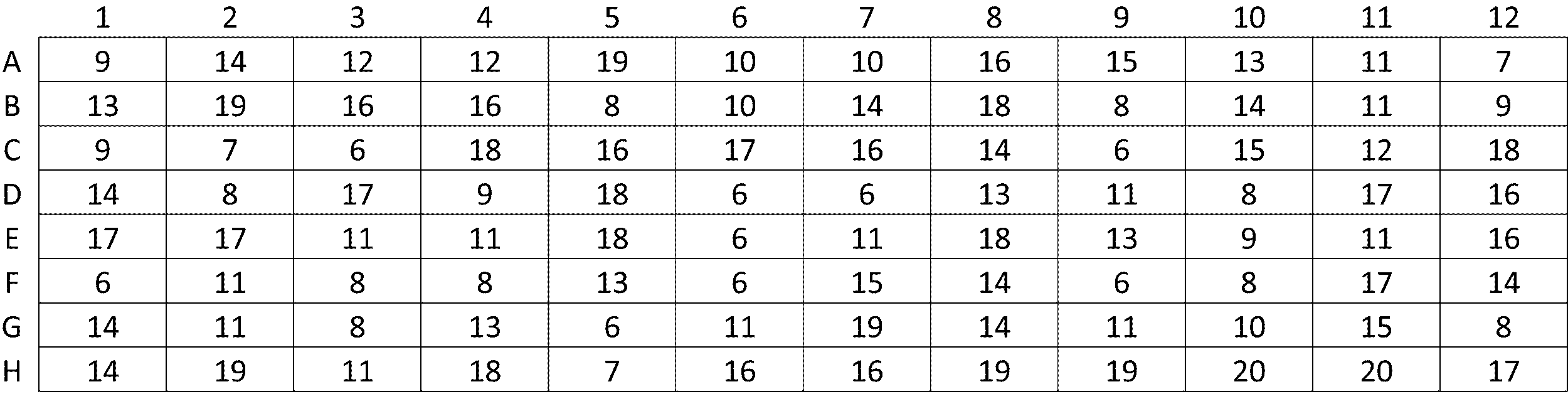
上記の自動分注機により,オイル源に貯めたミネラルオイルを各ウェルに,反応液の蒸発が抑制できるよう適量供給した。次に,各DNA検体の入ったマルチウェルプレート(第1のマルチウェル)をサーマルサイクラー上にロボットアームを用いて移送し、内蓋置き場に置かれた内蓋を,上記ロボットアームにより移送し,サーマルサイクラーに載置されたマルチウェルプレート(第1のマルチウェル)の上に置いて,被覆状態とした。次に可動蓋を,第1のマルチウェルを覆って加熱することができる加熱可能状態とした後,94℃でプレインキュベーションした。プレインキュベーションの後,反応液源に貯めたTaqポリメラーゼ(本発明における反応液)を,終濃度を25Units/mlとなるように,上記の自動分注機により,各ウェルに供給した。各DNA検体のPCRサイクル数の中で最も少ないサイクル数である6サイクルのPCRを行った。PCR条件は,94℃40秒,61℃40秒,72℃40秒とした。
6サイクルのPCR終了後,まず可動蓋の位置を第1のマルチウェルの上部から,初期位置に移動させ,加熱不要状態とした。次に内蓋を,上記ロボットアームを用いて移送し,内蓋置き場(内蓋初期位置)に載置した。次に,PCRサイクル数が6回のDNA検体を,自動分注機で回収し,サーキュレーターを用いた冷却機構を有する回収検体搭載部に搭載されたマルチウェルプレート(第2のマルチウェル)を,第1のマルチウェルのウェルと対応するウェルに移送した。
7サイクル目以降は6サイクル目と同様の手順で,各サイクルのPCRを行ったサンプルをマルチウェルプレート(第1のマルチウェル)からマルチウェルプレート(第2のマルチウェル)へ移送していき,これを最大サイクル数である20サイクル目まで繰り返した。
以上から,本発明の増幅工程により,濃度の異なる複数のDNA検体について,PCR増幅後の各検体のDNA濃度が一定の範囲内に収まることが確認された。
3 PCR装置
5 第1のマルチウェル
7 第2のマルチウェル
9 検体輸送部
11 サーマルサイクラー
13 プロセッサ
15 可動蓋
17 内蓋
19 オイル供給部
21 反応液供給部
23 磁性ビーズ回収用マグネット
31 入力部
33 出力部
35 制御部
37 演算部
39 記憶部
41 バス
Claims (12)
- 第1のマルチウェルの各ウェルに収容された各DNA検体についてPCRサイクル数を取得するサイクル数取得工程と,
前記サイクル数取得工程で得られた最も少ないサイクル数である最少サイクル数分のPCRを行う最少PCR工程と,
前記サイクル数取得工程で最少サイクル数である最少サイクル数とされた検体であって,前記最少サイクル数分のPCRを行った後の検体を,第2のマルチウェルに移送する第1の移送工程と,
第1の移送工程の後に,前記サイクル数取得工程で取得された最も多いサイクル数である最多サイクル数分まで,PCRをさらに行うとともに,前記サイクル数取得工程で取得されたサイクル数に到達した検体を,第2のマルチウェルに移送する追加PCR・移送工程を繰り返す工程を含む,
PCRを用いたDNAの増幅方法。 - 請求項1に記載の方法であって,
前記サイクル数取得工程は,前記ウェルに収容された前記各DNA検体のDNA濃度を用いて,増幅後のDNA濃度が一定範囲になるようなPCRサイクル数を取得する工程である,
方法。 - 請求項1に記載の方法であって,
前記各ウェルにおける前記各DNA検体は,複数種類のDNAを含み,当該複数種類のDNAは5’末端及び3’末端がそれぞれ共通した塩基配列を有する,方法。 - 請求項1に記載の方法であって,可動蓋と内蓋とを用い,
前記可動蓋は,第1のマルチウェルを覆って加熱することができる状態である加熱可能状態とすることができるとともに,前記加熱可能状態から移動することにより第1のマルチウェルを覆わない状態である加熱不要状態とすることができ,
前記内蓋は,第1のマルチウェルを覆う状態である被覆状態とすることができるとともに,前記被覆状態から移動することにより第1のマルチウェルを覆わない状態である開放状態とすることができ,前記可動蓋が前記加熱可能状態のときであって,前記内蓋が前記被覆状態のときに,前記可動蓋と第1のマルチウェルとの間に存在することとなり,
前記最少PCR工程において,前記内蓋を前記被覆状態とするとともに,前記可動蓋を前記加熱可能状態とし,
第1の移送工程において,前記可動蓋を前記加熱不要状態とするとともに,前記内蓋を前記開放状態とし,
前記追加PCR・移送工程においてPCRを行う際に,前記内蓋を前記被覆状態とするとともに,前記可動蓋を前記加熱可能状態とし,
前記追加PCR・移送工程において前記検体を第1のマルチウェルから第2のマルチウェルに移送する際に,前記可動蓋を前記加熱不要状態とするとともに,前記内蓋を前記開放状態とする,
方法。 - 請求項1に記載の方法であって,
第2のマルチウェルの各ウェルは,第1のマルチウェルの各ウェルと対応したウェルであり,
第1の移送工程において,
第1の移送工程における移送対象である前記検体を,第1のマルチウェルのウェルから,当該第1のマルチウェルのウェルと対応する第2のマルチウェルのウェルに移送し,
前記追加PCR・移送工程において前記検体を第1のマルチウェルから第2のマルチウェルに移送する際に,移送対象である検体を,第1のマルチウェルのウェルから,当該第1のマルチウェルのウェルと対応する第2のマルチウェルのウェルに移送する,
方法。 - 請求項1に記載の方法であって,
前記最少PCR工程の前に,オイル供給部が,第1のマルチウェルの各ウェルにオイルを供給する工程と,
前記最少PCR工程の前に,反応液供給部が,第1のマルチウェルの各ウェルに反応液を供給する工程と,をさらに含む,方法。 - プロセッサを含むPCR装置を用いてDNAを増幅するためのプログラムであって,
前記プログラムは,前記プロセッサに,
前記PCR装置の第1のマルチウェルの各ウェルに収容された各DNA検体についてPCRサイクル数が入力されるサイクル数入力工程と,
前記PCR装置に,前記サイクル数入力工程で入力された最も少ないサイクル数である最少サイクル数分のPCRを行わせる最少PCR工程と,
前記PCR装置に,前記サイクル数入力工程で最少サイクル数とされた検体であって,前記最少サイクル数分のPCRを行った後の検体を,第2のマルチウェルに移送させる第1の移送工程と,
前記PCR装置に,第1の移送工程の後に,前記サイクル数入力工程で入力された最も多いサイクル数である最多サイクル数分まで,PCRをさらに行わせるとともに,前記サイクル数入力工程で決定されたサイクル数に到達した検体を,第2のマルチウェルに移送させる追加PCR・移送工程を繰り返させる工程と,を実行させる,
プログラム。 - 請求項7に記載のプログラムを記憶した非一時的情報記録媒体。
- 第1のマルチウェル,第2のマルチウェル,検体輸送部,サーマルサイクラー,及びプロセッサを含む,PCR装置を用いたDNAの増幅システムであって,
前記プロセッサに,前記PCR装置の第1のマルチウェルの各ウェルに収容された各DNA検体についてPCRサイクル数が入力されるサイクル数入力工程と,
前記プロセッサが,第1のマルチウェルを搭載した前記サーマルサイクラーを駆動して,前記PCR装置に前記サイクル数入力工程で入力された最も少ないサイクル数である最少サイクル数分のPCRを行わせる最少PCR工程と,
前記プロセッサが,前記検体輸送部を用いて,前記サイクル数入力工程で最少サイクル数とされた検体であって,前記最少サイクル数分のPCRを行った後の検体を,第2のマルチウェルに移送させる第1の移送工程と,
第1の移送工程の後に,前記プロセッサが,前記サイクル数入力工程で入力された最も多いサイクル数である最多サイクル数分まで,第1のマルチウェルを搭載した前記サーマルサイクラーを駆動して,PCRをさらに行わせるとともに,前記検体輸送部を用いて,前記サイクル入力工程で入力されたサイクル数に到達した検体を,第2のマルチウェルに移送させる追加PCR・移送工程を繰り返させる,システム。 - 請求項9に記載のシステムであって,可動蓋と内蓋とをさらに有し,
前記可動蓋は,第1のマルチウェルを覆って加熱することができる状態である加熱可能状態とすることができるとともに,前記加熱可能状態から移動することにより第1のマルチウェルを覆わない状態である加熱不要状態とすることができ,
前記内蓋は,第1のマルチウェルを覆う状態である被覆状態とすることができるとともに,前記被覆状態から移動することにより第1のマルチウェルを覆わない状態である開放状態とすることができ,前記可動蓋が前記加熱可能状態のときであって,前記内蓋が前記被覆状態のときに,前記可動蓋と第1のマルチウェルとの間に存在することとなり,
前記最少PCR工程において,前記プロセッサが,前記内蓋を前記被覆状態とするとともに,前記可動蓋を前記加熱可能状態とし,
第1の移送工程において,前記プロセッサが,前記可動蓋を前記加熱不要状態とするとともに,前記内蓋を前記開放状態とし,
前記追加PCR・移送工程においてPCRを行う際に,前記プロセッサが,前記内蓋を前記被覆状態とするとともに,前記可動蓋を前記加熱可能状態とし,
前記追加PCR・移送工程において前記検体を第1のマルチウェルから第2のマルチウェルに移送する際に,前記プロセッサが,前記可動蓋を前記加熱不要状態とするとともに,前記内蓋を前記開放状態とする,
システム。 - 請求項9に記載のシステムであって,
第2のマルチウェルの各ウェルは,第1のマルチウェルの各ウェルと対応したウェルであり,
第1の移送工程において,前記プロセッサが,第1の移送工程における移送対象である前記検体を,第1のマルチウェルのウェルから,当該第1のマルチウェルのウェルと対応する第2のマルチウェルのウェルに移送させ,
前記追加PCR・移送工程において前記検体を第1のマルチウェルから第2のマルチウェルに移送する際に,前記プロセッサが,移送対象である検体を,第1のマルチウェルのウェルから,当該第1のマルチウェルのウェルと対応する第2のマルチウェルのウェルに移送させる,
システム。 - 請求項9に記載のシステムであって,
第1のマルチウェルの各ウェルにオイルを供給するオイル供給部,及び
第1のマルチウェルの各ウェルに反応液を供給する反応液供給部をさらに有し,
前記最少PCR工程の前に,前記プロセッサが,前記オイル供給部に,第1のマルチウェルの各ウェルにオイルを供給させ,
前記最少PCR工程の前に,前記プロセッサが,前記反応液供給部に,第1のマルチウェルの各ウェルに反応液を供給させる,
システム。
Priority Applications (3)
| Application Number | Priority Date | Filing Date | Title |
|---|---|---|---|
| EP23907054.3A EP4640846A1 (en) | 2022-12-23 | 2023-12-19 | Dna amplification method using pcr |
| AU2023409463A AU2023409463A1 (en) | 2022-12-23 | 2023-12-19 | Dna amplification method using pcr |
| JP2024566088A JPWO2024135694A1 (ja) | 2022-12-23 | 2023-12-19 |
Applications Claiming Priority (2)
| Application Number | Priority Date | Filing Date | Title |
|---|---|---|---|
| JP2022-206306 | 2022-12-23 | ||
| JP2022206306 | 2022-12-23 |
Publications (1)
| Publication Number | Publication Date |
|---|---|
| WO2024135694A1 true WO2024135694A1 (ja) | 2024-06-27 |
Family
ID=91588582
Family Applications (1)
| Application Number | Title | Priority Date | Filing Date |
|---|---|---|---|
| PCT/JP2023/045552 Ceased WO2024135694A1 (ja) | 2022-12-23 | 2023-12-19 | Pcrを用いたdnaの増幅方法 |
Country Status (4)
| Country | Link |
|---|---|
| EP (1) | EP4640846A1 (ja) |
| JP (1) | JPWO2024135694A1 (ja) |
| AU (1) | AU2023409463A1 (ja) |
| WO (1) | WO2024135694A1 (ja) |
Citations (11)
| Publication number | Priority date | Publication date | Assignee | Title |
|---|---|---|---|---|
| WO1998031700A1 (en) | 1997-01-21 | 1998-07-23 | The General Hospital Corporation | Selection of proteins using rna-protein fusions |
| WO2007066627A1 (ja) | 2005-12-06 | 2007-06-14 | The University Of Tokyo | 多目的アシル化触媒とその用途 |
| WO2011049157A1 (ja) | 2009-10-22 | 2011-04-28 | ペプチドリーム株式会社 | ペプチド翻訳合成におけるrapidディスプレイ法 |
| WO2012074130A1 (ja) | 2010-12-03 | 2012-06-07 | 国立大学法人東京大学 | ペプチドライブラリーの製造方法、ペプチドライブラリー、及びスクリーニング方法 |
| WO2014119600A1 (ja) | 2013-01-30 | 2014-08-07 | ペプチドリーム株式会社 | Flexible Display法 |
| JP2014534497A (ja) * | 2011-09-30 | 2014-12-18 | ライフ テクノロジーズ コーポレーション | データを視覚化し評価する方法およびシステム |
| WO2016159211A1 (ja) | 2015-03-31 | 2016-10-06 | 国立大学法人埼玉大学 | 試験管内淘汰及び分子間相互作用解析用高速光架橋型共用リンカー、そのリンカーを用いた試験管内淘汰方法 |
| JP2019531730A (ja) * | 2016-09-28 | 2019-11-07 | ジェネラル オートメーション ラボ テクノロジーズ インコーポレイテッド | 細菌群の関係決定及び他のハイスループット微生物学適用高分解能システム、キット、装置、並びに方法 |
| WO2021150426A1 (en) * | 2020-01-21 | 2021-07-29 | Microsoft Technology Licensing, Llc | Efficient random access to dna-encoded data |
| JP2021532802A (ja) * | 2018-08-03 | 2021-12-02 | ローベルト ボツシユ ゲゼルシヤフト ミツト ベシユレンクテル ハフツングRobert Bosch Gmbh | リアルタイムpcrを実施する方法 |
| WO2022081934A1 (en) | 2020-10-15 | 2022-04-21 | Genentech, Inc. | Multiplexed target-binding candidate screening analysis |
-
2023
- 2023-12-19 EP EP23907054.3A patent/EP4640846A1/en active Pending
- 2023-12-19 AU AU2023409463A patent/AU2023409463A1/en active Pending
- 2023-12-19 WO PCT/JP2023/045552 patent/WO2024135694A1/ja not_active Ceased
- 2023-12-19 JP JP2024566088A patent/JPWO2024135694A1/ja active Pending
Patent Citations (11)
| Publication number | Priority date | Publication date | Assignee | Title |
|---|---|---|---|---|
| WO1998031700A1 (en) | 1997-01-21 | 1998-07-23 | The General Hospital Corporation | Selection of proteins using rna-protein fusions |
| WO2007066627A1 (ja) | 2005-12-06 | 2007-06-14 | The University Of Tokyo | 多目的アシル化触媒とその用途 |
| WO2011049157A1 (ja) | 2009-10-22 | 2011-04-28 | ペプチドリーム株式会社 | ペプチド翻訳合成におけるrapidディスプレイ法 |
| WO2012074130A1 (ja) | 2010-12-03 | 2012-06-07 | 国立大学法人東京大学 | ペプチドライブラリーの製造方法、ペプチドライブラリー、及びスクリーニング方法 |
| JP2014534497A (ja) * | 2011-09-30 | 2014-12-18 | ライフ テクノロジーズ コーポレーション | データを視覚化し評価する方法およびシステム |
| WO2014119600A1 (ja) | 2013-01-30 | 2014-08-07 | ペプチドリーム株式会社 | Flexible Display法 |
| WO2016159211A1 (ja) | 2015-03-31 | 2016-10-06 | 国立大学法人埼玉大学 | 試験管内淘汰及び分子間相互作用解析用高速光架橋型共用リンカー、そのリンカーを用いた試験管内淘汰方法 |
| JP2019531730A (ja) * | 2016-09-28 | 2019-11-07 | ジェネラル オートメーション ラボ テクノロジーズ インコーポレイテッド | 細菌群の関係決定及び他のハイスループット微生物学適用高分解能システム、キット、装置、並びに方法 |
| JP2021532802A (ja) * | 2018-08-03 | 2021-12-02 | ローベルト ボツシユ ゲゼルシヤフト ミツト ベシユレンクテル ハフツングRobert Bosch Gmbh | リアルタイムpcrを実施する方法 |
| WO2021150426A1 (en) * | 2020-01-21 | 2021-07-29 | Microsoft Technology Licensing, Llc | Efficient random access to dna-encoded data |
| WO2022081934A1 (en) | 2020-10-15 | 2022-04-21 | Genentech, Inc. | Multiplexed target-binding candidate screening analysis |
Non-Patent Citations (3)
| Title |
|---|
| See also references of EP4640846A1 |
| T. ISHIZUKA ET AL., AM. CHEM. SOC., vol. 135, no. 14, 2013, pages 5433 - 5440 |
| T. KONDO ET AL., CHEM. COMMUN., vol. 57, 2021, pages 2416 - 2419 |
Also Published As
| Publication number | Publication date |
|---|---|
| AU2023409463A1 (en) | 2025-07-10 |
| JPWO2024135694A1 (ja) | 2024-06-27 |
| EP4640846A1 (en) | 2025-10-29 |
Similar Documents
| Publication | Publication Date | Title |
|---|---|---|
| JP5258835B2 (ja) | ポリヌクレオチドの検出及び定量装置 | |
| AU2013350823B2 (en) | Handling liquid samples | |
| DK2350648T3 (en) | SELECTIVE PROCESSING OF BIOLOGICAL MATERIAL ON A MICROARRAY SUBSTRATE | |
| WO2010094772A1 (en) | Synthesis of sequence-verified nucleic acids | |
| JP5856958B2 (ja) | 簡易核酸増幅装置及び簡易核酸増幅装置の使用方法 | |
| US20230212561A1 (en) | Accurate sequencing library generation via ultra-high partitioning | |
| JP2019131539A (ja) | 次世代シーケンシングにおける検体間相互汚染の検出方法 | |
| US20210363517A1 (en) | High throughput amplification and detection of short rna fragments | |
| JP2005538734A (ja) | 自動液体処理中のrna及び逆転写酵素の保存 | |
| Cinnioglu et al. | Aneuploidy screening using next generation sequencing | |
| Obata et al. | Recent developments in laboratory automation using magnetic particles for genome analysis | |
| WO2024135694A1 (ja) | Pcrを用いたdnaの増幅方法 | |
| Allen et al. | Mitochondrial D-loop and coding sequence analysis using pyrosequencing | |
| JP4556230B2 (ja) | 核酸検出容器 | |
| CN112020564A (zh) | 用于线性样品加工的方法 | |
| US20230417787A1 (en) | Fully automated sample processing platform from extraction to sequencing | |
| US20230249178A1 (en) | Split-pool synthesis apparatus and methods of performing split-pool synthesis | |
| Juang et al. | Oil Immersed Lossless Total Analysis System (OIL-TAS): Integrated RNA Extraction and Detection for SARS-CoV-2 Testing | |
| TW202509203A (zh) | 自動化分子操作系統 | |
| JP2008154490A (ja) | 複数種類の標的塩基配列を同時に増幅するために用いられる基板と、該基板を用いた塩基配列の増幅方法 |
Legal Events
| Date | Code | Title | Description |
|---|---|---|---|
| 121 | Ep: the epo has been informed by wipo that ep was designated in this application |
Ref document number: 23907054 Country of ref document: EP Kind code of ref document: A1 |
|
| WWE | Wipo information: entry into national phase |
Ref document number: 2024566088 Country of ref document: JP |
|
| WWE | Wipo information: entry into national phase |
Ref document number: AU2023409463 Country of ref document: AU |
|
| ENP | Entry into the national phase |
Ref document number: 2023409463 Country of ref document: AU Date of ref document: 20231219 Kind code of ref document: A |
|
| WWE | Wipo information: entry into national phase |
Ref document number: 2023907054 Country of ref document: EP |
|
| NENP | Non-entry into the national phase |
Ref country code: DE |
|
| ENP | Entry into the national phase |
Ref document number: 2023907054 Country of ref document: EP Effective date: 20250723 |
|
| WWE | Wipo information: entry into national phase |
Ref document number: 11202504225S Country of ref document: SG |
|
| WWP | Wipo information: published in national office |
Ref document number: 11202504225S Country of ref document: SG |
|
| ENP | Entry into the national phase |
Ref document number: 2023907054 Country of ref document: EP Effective date: 20250723 |
|
| ENP | Entry into the national phase |
Ref document number: 2023907054 Country of ref document: EP Effective date: 20250723 |
|
| WWP | Wipo information: published in national office |
Ref document number: 2023907054 Country of ref document: EP |