WO2024142579A1 - 打ち抜き加工性に優れる無方向性電磁鋼板 - Google Patents
打ち抜き加工性に優れる無方向性電磁鋼板 Download PDFInfo
- Publication number
- WO2024142579A1 WO2024142579A1 PCT/JP2023/039033 JP2023039033W WO2024142579A1 WO 2024142579 A1 WO2024142579 A1 WO 2024142579A1 JP 2023039033 W JP2023039033 W JP 2023039033W WO 2024142579 A1 WO2024142579 A1 WO 2024142579A1
- Authority
- WO
- WIPO (PCT)
- Prior art keywords
- mass
- less
- steel sheet
- class
- particle size
- Prior art date
- Legal status (The legal status is an assumption and is not a legal conclusion. Google has not performed a legal analysis and makes no representation as to the accuracy of the status listed.)
- Ceased
Links
Images


Classifications
-
- C—CHEMISTRY; METALLURGY
- C21—METALLURGY OF IRON
- C21D—MODIFYING THE PHYSICAL STRUCTURE OF FERROUS METALS; GENERAL DEVICES FOR HEAT TREATMENT OF FERROUS OR NON-FERROUS METALS OR ALLOYS; MAKING METAL MALLEABLE, e.g. BY DECARBURISATION OR TEMPERING
- C21D6/00—Heat treatment of ferrous alloys
- C21D6/008—Heat treatment of ferrous alloys containing Si
-
- C—CHEMISTRY; METALLURGY
- C21—METALLURGY OF IRON
- C21D—MODIFYING THE PHYSICAL STRUCTURE OF FERROUS METALS; GENERAL DEVICES FOR HEAT TREATMENT OF FERROUS OR NON-FERROUS METALS OR ALLOYS; MAKING METAL MALLEABLE, e.g. BY DECARBURISATION OR TEMPERING
- C21D8/00—Modifying the physical properties of ferrous metals or ferrous alloys by deformation combined with, or followed by, heat treatment
- C21D8/12—Modifying the physical properties of ferrous metals or ferrous alloys by deformation combined with, or followed by, heat treatment during manufacturing of articles with special electromagnetic properties
-
- C—CHEMISTRY; METALLURGY
- C21—METALLURGY OF IRON
- C21D—MODIFYING THE PHYSICAL STRUCTURE OF FERROUS METALS; GENERAL DEVICES FOR HEAT TREATMENT OF FERROUS OR NON-FERROUS METALS OR ALLOYS; MAKING METAL MALLEABLE, e.g. BY DECARBURISATION OR TEMPERING
- C21D9/00—Heat treatment, e.g. annealing, hardening, quenching or tempering, adapted for particular articles; Furnaces therefor
- C21D9/46—Heat treatment, e.g. annealing, hardening, quenching or tempering, adapted for particular articles; Furnaces therefor for sheet metals
-
- C—CHEMISTRY; METALLURGY
- C22—METALLURGY; FERROUS OR NON-FERROUS ALLOYS; TREATMENT OF ALLOYS OR NON-FERROUS METALS
- C22C—ALLOYS
- C22C38/00—Ferrous alloys, e.g. steel alloys
- C22C38/002—Ferrous alloys, e.g. steel alloys containing In, Mg, or other elements not provided for in one single group C22C38/001 - C22C38/60
-
- C—CHEMISTRY; METALLURGY
- C22—METALLURGY; FERROUS OR NON-FERROUS ALLOYS; TREATMENT OF ALLOYS OR NON-FERROUS METALS
- C22C—ALLOYS
- C22C38/00—Ferrous alloys, e.g. steel alloys
- C22C38/004—Very low carbon steels, i.e. having a carbon content of less than 0,01%
-
- C—CHEMISTRY; METALLURGY
- C22—METALLURGY; FERROUS OR NON-FERROUS ALLOYS; TREATMENT OF ALLOYS OR NON-FERROUS METALS
- C22C—ALLOYS
- C22C38/00—Ferrous alloys, e.g. steel alloys
- C22C38/005—Ferrous alloys, e.g. steel alloys containing rare earths, i.e. Sc, Y, Lanthanides
-
- C—CHEMISTRY; METALLURGY
- C22—METALLURGY; FERROUS OR NON-FERROUS ALLOYS; TREATMENT OF ALLOYS OR NON-FERROUS METALS
- C22C—ALLOYS
- C22C38/00—Ferrous alloys, e.g. steel alloys
- C22C38/008—Ferrous alloys, e.g. steel alloys containing tin
-
- C—CHEMISTRY; METALLURGY
- C22—METALLURGY; FERROUS OR NON-FERROUS ALLOYS; TREATMENT OF ALLOYS OR NON-FERROUS METALS
- C22C—ALLOYS
- C22C38/00—Ferrous alloys, e.g. steel alloys
- C22C38/02—Ferrous alloys, e.g. steel alloys containing silicon
-
- C—CHEMISTRY; METALLURGY
- C22—METALLURGY; FERROUS OR NON-FERROUS ALLOYS; TREATMENT OF ALLOYS OR NON-FERROUS METALS
- C22C—ALLOYS
- C22C38/00—Ferrous alloys, e.g. steel alloys
- C22C38/04—Ferrous alloys, e.g. steel alloys containing manganese
-
- C—CHEMISTRY; METALLURGY
- C22—METALLURGY; FERROUS OR NON-FERROUS ALLOYS; TREATMENT OF ALLOYS OR NON-FERROUS METALS
- C22C—ALLOYS
- C22C38/00—Ferrous alloys, e.g. steel alloys
- C22C38/06—Ferrous alloys, e.g. steel alloys containing aluminium
-
- C—CHEMISTRY; METALLURGY
- C22—METALLURGY; FERROUS OR NON-FERROUS ALLOYS; TREATMENT OF ALLOYS OR NON-FERROUS METALS
- C22C—ALLOYS
- C22C38/00—Ferrous alloys, e.g. steel alloys
- C22C38/08—Ferrous alloys, e.g. steel alloys containing nickel
-
- C—CHEMISTRY; METALLURGY
- C22—METALLURGY; FERROUS OR NON-FERROUS ALLOYS; TREATMENT OF ALLOYS OR NON-FERROUS METALS
- C22C—ALLOYS
- C22C38/00—Ferrous alloys, e.g. steel alloys
- C22C38/10—Ferrous alloys, e.g. steel alloys containing cobalt
-
- C—CHEMISTRY; METALLURGY
- C22—METALLURGY; FERROUS OR NON-FERROUS ALLOYS; TREATMENT OF ALLOYS OR NON-FERROUS METALS
- C22C—ALLOYS
- C22C38/00—Ferrous alloys, e.g. steel alloys
- C22C38/12—Ferrous alloys, e.g. steel alloys containing tungsten, tantalum, molybdenum, vanadium, or niobium
-
- C—CHEMISTRY; METALLURGY
- C22—METALLURGY; FERROUS OR NON-FERROUS ALLOYS; TREATMENT OF ALLOYS OR NON-FERROUS METALS
- C22C—ALLOYS
- C22C38/00—Ferrous alloys, e.g. steel alloys
- C22C38/14—Ferrous alloys, e.g. steel alloys containing titanium or zirconium
-
- C—CHEMISTRY; METALLURGY
- C22—METALLURGY; FERROUS OR NON-FERROUS ALLOYS; TREATMENT OF ALLOYS OR NON-FERROUS METALS
- C22C—ALLOYS
- C22C38/00—Ferrous alloys, e.g. steel alloys
- C22C38/16—Ferrous alloys, e.g. steel alloys containing copper
-
- C—CHEMISTRY; METALLURGY
- C22—METALLURGY; FERROUS OR NON-FERROUS ALLOYS; TREATMENT OF ALLOYS OR NON-FERROUS METALS
- C22C—ALLOYS
- C22C38/00—Ferrous alloys, e.g. steel alloys
- C22C38/18—Ferrous alloys, e.g. steel alloys containing chromium
- C22C38/34—Ferrous alloys, e.g. steel alloys containing chromium with more than 1.5% by weight of silicon
-
- C—CHEMISTRY; METALLURGY
- C22—METALLURGY; FERROUS OR NON-FERROUS ALLOYS; TREATMENT OF ALLOYS OR NON-FERROUS METALS
- C22C—ALLOYS
- C22C38/00—Ferrous alloys, e.g. steel alloys
- C22C38/60—Ferrous alloys, e.g. steel alloys containing lead, selenium, tellurium, or antimony, or more than 0.04% by weight of sulfur
-
- H—ELECTRICITY
- H01—ELECTRIC ELEMENTS
- H01F—MAGNETS; INDUCTANCES; TRANSFORMERS; SELECTION OF MATERIALS FOR THEIR MAGNETIC PROPERTIES
- H01F1/00—Magnets or magnetic bodies characterised by the magnetic materials therefor; Selection of materials for their magnetic properties
- H01F1/01—Magnets or magnetic bodies characterised by the magnetic materials therefor; Selection of materials for their magnetic properties of inorganic materials
- H01F1/03—Magnets or magnetic bodies characterised by the magnetic materials therefor; Selection of materials for their magnetic properties of inorganic materials characterised by their coercivity
- H01F1/12—Magnets or magnetic bodies characterised by the magnetic materials therefor; Selection of materials for their magnetic properties of inorganic materials characterised by their coercivity of soft-magnetic materials
- H01F1/14—Magnets or magnetic bodies characterised by the magnetic materials therefor; Selection of materials for their magnetic properties of inorganic materials characterised by their coercivity of soft-magnetic materials metals or alloys
- H01F1/147—Alloys characterised by their composition
- H01F1/14766—Fe-Si based alloys
- H01F1/14775—Fe-Si based alloys in the form of sheets
-
- H—ELECTRICITY
- H01—ELECTRIC ELEMENTS
- H01F—MAGNETS; INDUCTANCES; TRANSFORMERS; SELECTION OF MATERIALS FOR THEIR MAGNETIC PROPERTIES
- H01F1/00—Magnets or magnetic bodies characterised by the magnetic materials therefor; Selection of materials for their magnetic properties
- H01F1/01—Magnets or magnetic bodies characterised by the magnetic materials therefor; Selection of materials for their magnetic properties of inorganic materials
- H01F1/03—Magnets or magnetic bodies characterised by the magnetic materials therefor; Selection of materials for their magnetic properties of inorganic materials characterised by their coercivity
- H01F1/12—Magnets or magnetic bodies characterised by the magnetic materials therefor; Selection of materials for their magnetic properties of inorganic materials characterised by their coercivity of soft-magnetic materials
- H01F1/14—Magnets or magnetic bodies characterised by the magnetic materials therefor; Selection of materials for their magnetic properties of inorganic materials characterised by their coercivity of soft-magnetic materials metals or alloys
- H01F1/147—Alloys characterised by their composition
- H01F1/14766—Fe-Si based alloys
- H01F1/14791—Fe-Si-Al based alloys, e.g. Sendust
-
- C—CHEMISTRY; METALLURGY
- C21—METALLURGY OF IRON
- C21D—MODIFYING THE PHYSICAL STRUCTURE OF FERROUS METALS; GENERAL DEVICES FOR HEAT TREATMENT OF FERROUS OR NON-FERROUS METALS OR ALLOYS; MAKING METAL MALLEABLE, e.g. BY DECARBURISATION OR TEMPERING
- C21D2261/00—Machining or cutting being involved
Definitions
- the present invention relates to a non-oriented electrical steel sheet that has low iron loss and excellent punching workability.
- Patent Document 1 discloses a non-oriented electrical steel that contains Si: 1.5 mass% or less, Mn: 0.4 mass% to 1.5 mass% or less, sol. Al: 0.01 mass% to 0.04 mass% or less, Ti: 0.0015 mass% or less, N: 0.0030 mass% or less, S: 0.0010 mass% to 0.0040 mass% or less, B with a B/N ratio of 0.5 to 1.5, and the remainder being Fe and unavoidable impurities, in which 10% or more of sulfides containing Mn are compound precipitated with B precipitates to obtain an appropriate crystal grain size, thereby ensuring punching workability.
- Patent Document 2 also discloses a non-oriented electrical steel with excellent magnetic properties and punching workability, which contains C: 0.003 mass% or less, Si: 1.0 mass% to 3.0 mass% or less, Al: 0.1 mass% to 3.0 mass% or less, Mn: 0.1 mass% to 1.0 mass% or less, the Al and Si contents satisfy the relationship 0.2 ⁇ Al/(Si+Al) ⁇ 0.6, the balance being Fe and unavoidable impurities.
- Patent Document 2 also discloses a non-oriented electrical steel with excellent magnetic properties and punching workability, which has a yield ratio expressed as (yield strength/tensile strength) of 0.6 or more and a Vickers hardness of 200 or less.
- the electrical steel sheet described in Patent Document 1 has a Si content of 1.5 mass% or less, and cannot be applied directly to non-oriented electrical steel sheets with a higher Si content.
- the electrical steel sheet described in Patent Document 2 must have a Vickers hardness of 200 or less, and therefore cannot be applied to non-oriented electrical steel sheets with a high Si content.
- the non-oriented electrical steel sheet described in Patent Document 1 and the non-oriented electrical steel sheet described in Patent Document 2 are technologies that improve punching workability by controlling the crystal grain size and by controlling the mechanical properties of the parent phase, respectively, but it is difficult to achieve further improvements in punching workability using these methods alone.
- the present invention was made in consideration of the above problems with the conventional technology, and its purpose is to provide a high-Si non-oriented electrical steel sheet that improves punching workability without deteriorating iron loss characteristics, using a method different from that of the conventional technology.
- the inventors conducted extensive research to achieve the above object. As a result, they discovered that adding Pb to the steel material improves the punching workability of the steel sheet, and that the deterioration of magnetic properties caused by the addition of Pb can be prevented by adding an appropriate amount of Zn to control the particle size distribution of second phase particles such as inclusions present in the steel sheet within an appropriate range, thereby improving punching workability without causing deterioration of iron loss, which led to the development of the present invention.
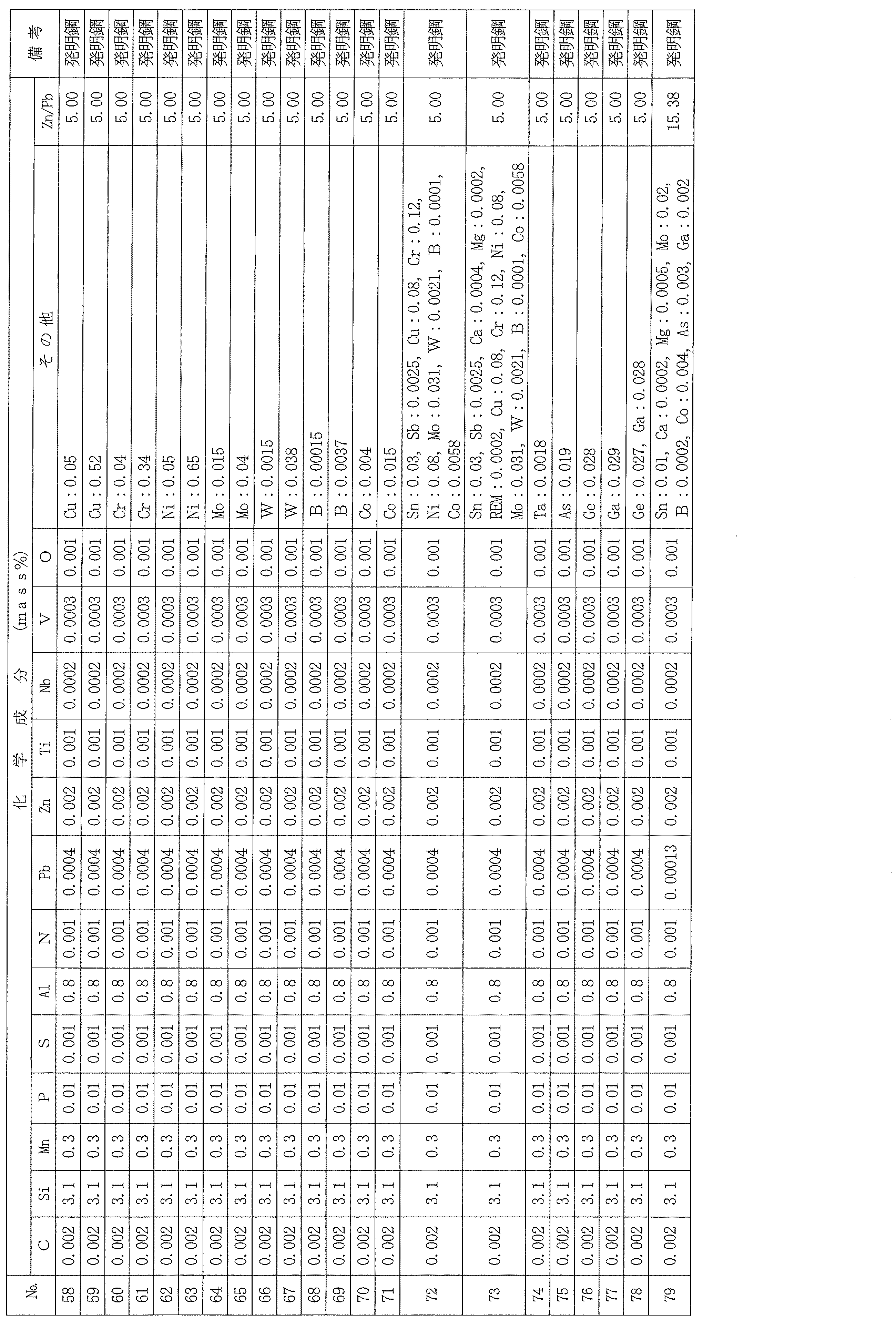
- the present invention provides a steel sheet having a composition of C: 0.0050 mass% or less, Si: 2.5 to 6.5 mass%, Mn: 0.05 to 2.0 mass%, P: 0.10 mass% or less, S: 0.0050 mass% or less, Al: 0.30 to 2.0 mass%, N: 0.010 mass% or less, Pb: 0.00010 to 0.010 mass%, Zn: 0.0 0.005 to 0.020 mass%, Ti: 0.0050 mass% or less, Nb: 0.0050 mass% or less, V: 0.0050 mass% or less, and O: 0.0050 mass% or less, and the contents (mass%) of Pb and Zn are represented as [Pb] and [Zn], respectively, and the [Pb] and [Zn] are represented by the following formula (1); [Zn]/[Pb] ⁇ 1.58 ...
- (1) and the balance consisting of Fe and unavoidable impurities, and the particle size distribution of second phase particles having a particle size of 0.10 ⁇ m or more and less than 5.00 ⁇ m present in a sheet thickness cross section in the rolling direction is represented in a histogram with the particle size as classes, the number density as frequencies, and the class width as 0.10 ⁇ m, the particle size distribution satisfies the following formula (2):
- d i class value ( ⁇ m) of class i
- N si frequency of class i (pieces/ ⁇ m 2 )
- the non-oriented electrical steel sheet is characterized by satisfying the following:
- the non-oriented electrical steel sheet of the present invention is characterized in that the average grain size of second phase particles having a grain size of 0.10 ⁇ m or more and less than 5.00 ⁇ m within the sheet thickness cross section in the rolling direction is 0.40 ⁇ m or more.
- the non-oriented electrical steel sheet of the present invention is characterized in that it further contains, in addition to the above-mentioned chemical composition, at least one component selected from the following groups A to I: Group A: At least one of Sn and Sb: 0.005 to 0.20 mass% in total Group B: At least one of Ca, Mg and REM: 0.0005 to 0.020 mass% in total C group: at least one of Cr, Cu and Ni: 0.01 to 1.0 mass% in total Group D: at least one of Mo: 0.001 to 0.050 mass% and W: 0.001 to 0.050 mass% Group E: B: 0.0001 to 0.0040 mass% Group F: Co: 0.0005 to 0.0200 mass% G group: Ta: 0 to 0.0020 mass% H group; As: 0 to 0.020 mass% Group I: at least one of Ge: 0 to 0.030 mass% and Ga: 0 to 0.030 mass%
- the present invention makes it possible to improve the punching workability of non-oriented electrical steel sheets with a high Si content without causing deterioration of the iron loss characteristics, making it possible to provide non-oriented electrical steel sheets suitable as core materials for motors, transformers, and the like, which are manufactured by punching.
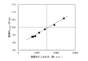
- 1 is a graph showing the effect of Pb content on the burr height of a punched cut surface. 1 is a graph showing the effect of Zn content on the pinning force of a domain wall. 1 is a graph showing the effect of the pinning force of a domain wall on iron loss.
- Example 1 A steel having a component composition containing C: 0.0020 mass%, Si: 2.9 mass%, Mn: 0.2 mass%, P: 0.01 mass%, S: 0.0020 mass%, Al: 0.4 mass%, N: 0.0012 mass%, Ti: 0.0010 mass%, Nb: 0.0001 mass%, V: 0.0005 mass%, and O: 0.0010 mass%, and further containing Pb in a range of 0.00001 to 0.022 mass%, with the balance being Fe and unavoidable impurities, was melted in a vacuum melting furnace and cast into a steel ingot.
- the above steel ingot was hot rolled to form a hot-rolled sheet having a thickness of 1.8 mm, which was subjected to hot-rolled sheet annealing at 1000°C for 30 seconds, followed by pickling and cold rolling to form a cold-rolled sheet having a final thickness of 0.25 mm, which was then subjected to finish annealing at 1000°C for 10 seconds.
- disk-shaped test pieces with a diameter of 10 mm were taken from the steel sheets after the above-mentioned finish annealing by punching with a clearance set to 5%.
- a new die was used for punching for each steel sheet, and the height of the burrs that occurred at the cut ends at both ends in the rolling direction of the disk-shaped test pieces after punching 1 million times was measured, and the punchability of the steel sheet was evaluated from the average value of these values.
- Figure 1 shows the relationship between the Pb content in the steel material and the burr height after 1 million punchings. This figure shows that by adding 0.00010 mass% or more of Pb, the burr height is reduced to 30 ⁇ m or less, improving punching workability.
- Example 2 A steel having a component composition containing C: 0.0020 mass%, Si: 3.1 mass%, Mn: 0.3 mass%, P: 0.01 mass%, S: 0.0020 mass%, Al: 0.8 mass%, N: 0.0010 mass%, Pb: 0.003 mass%, Ti: 0.0015 mass%, Nb: 0.0002 mass%, V: 0.0010 mass%, and O: 0.0010 mass%, Zn content varying in the range of 0.0001 to 0.052 mass%, and the balance being Fe and unavoidable impurities, was melted in a vacuum melting furnace and cast into a steel ingot.
- the above steel ingot was hot rolled to form a hot-rolled sheet having a thickness of 1.5 mm, which was then subjected to hot-rolled sheet annealing at 1020°C for 30 seconds, followed by pickling and cold rolling to form a cold-rolled sheet having a final thickness of 0.25 mm.
- the cold-rolled sheet was then subjected to finish annealing at 1000°C for 10 seconds.
- test pieces each having a width of 30 mm and a length of 280 mm, were taken from the steel sheet after the above-mentioned finish annealing by shearing, with the length direction being the rolling direction (L direction) or the sheet width direction (C direction).
- L direction rolling direction
- C direction sheet width direction
- the same number of test pieces in the L direction and C direction were stacked in an Epstein testing machine, and the iron loss W 10/400 was measured by the method described in JIS C 2550.
- the plate thickness cross section (total plate thickness) in the rolling direction of the test piece was observed over a range of 2 mm2 or more using a scanning microscope SEM, and the particle size of the second phase particles present in the above range was measured.
- the second phase particles refer to inclusions or precipitates that form a phase other than the ferrite phase, which is the parent phase, and specifically refer to oxide-based inclusions, carbonitrides, sulfides, borides, and their composites.
- the particle size of the second phase particles refers to the average value of the Feret diameter in the rolling direction and the Feret diameter in the plate thickness direction.
- the second phase particles whose particle size was measured were those with a particle size of 0.10 ⁇ m or more.
- an SEM is used to measure the particle size of the second phase particles, but there are no particular limitations on the method as long as it is capable of observing particles of 0.10 ⁇ m or more. However, it is preferable to use an SEM in terms of ease of sample preparation and the ability to observe a wide range.
- the iron loss W 10/400 also decreases as the pinning force of the domain wall decreases, and in particular, when the pinning force of the domain wall is 0.0015 pieces ⁇ m ⁇ 1 or less, the iron loss W 10/400 shows a good value of 10.0 W/kg or less. From the above results, it was found that in order to suppress the iron loss deterioration due to the addition of Pb, it is important to add Zn to optimize the particle size distribution of the second phase particles and reduce the "pinning force of the domain wall" defined by the above formula (3) to a predetermined value or less.
- Al 0.30 to 2.0 mass%
- Al is an element that has the effect of increasing the resistivity of steel, reducing iron loss, and increasing the strength of steel.
- the content exceeds 2.0 mass%, the steel becomes brittle and difficult to roll, so the upper limit is set to 2.0 mass%.
- the content of Al is less than 0.30 mass%, fine nitrides are formed and precipitated, which deteriorates the iron loss characteristics, so the lower limit is set to 0.30 mass%.
- the preferred range is 0.4 to 1.5 mass%.
- N 0.010 mass% or less N is a harmful element that forms nitrides and precipitates, degrading magnetic properties, so it is limited to 0.010 mass% or less, preferably 0.0060 mass% or less.
- 0 to 0.020 mass% As is an element that increases the hardness of steel and can be added to adjust mechanical properties. In order to reliably obtain the above effect, it is preferable to add 0.001 mass% or more. On the other hand, As is also an element that embrittles steel, and the above adverse effects become significant especially when it exceeds 0.020 mass%, so the upper limit is set to 0.020 mass%. More preferably, it is in the range of 0.003 to 0.010 mass%.
- the non-oriented electrical steel sheet of the present invention may be produced by any known method without any particular limitation, but an example of a preferred production method will be described below.
Landscapes
- Chemical & Material Sciences (AREA)
- Engineering & Computer Science (AREA)
- Organic Chemistry (AREA)
- Materials Engineering (AREA)
- Mechanical Engineering (AREA)
- Metallurgy (AREA)
- Physics & Mathematics (AREA)
- Electromagnetism (AREA)
- Dispersion Chemistry (AREA)
- Power Engineering (AREA)
- Thermal Sciences (AREA)
- Crystallography & Structural Chemistry (AREA)
- Manufacturing & Machinery (AREA)
- Soft Magnetic Materials (AREA)
- Manufacturing Of Steel Electrode Plates (AREA)
Abstract
Description
[Zn]/[Pb]≧1.58 ・・・(1)
を満たし、残部がFeおよび不可避的不純物からなる成分組成を有し、圧延方向の板厚断面内に存在する粒径が0.10μm以上5.00μm未満の第2相粒子の粒径分布を、粒径を階級、個数密度を度数、階級幅を0.10μmとするヒストグラムに表したとき、上記粒径分布が下記(2)式;

を満たすことを特徴とする無方向性電磁鋼板である。
記
・A群;SnおよびSbのうちの少なくとも1種:合計で0.005~0.20mass%
・B群;Ca、MgおよびREMのうちの少なくとも1種:合計で0.0005~0.020mass%
・C群;Cr、CuおよびNiのうちの少なくとも1種:合計で0.01~1.0mass%
・D群;Mo:0.001~0.050mass%およびW:0.001~0.050mass%のうちの少なくとも1種
・E群;B:0.0001~0.0040mass%
・F群;Co:0.0005~0.0200mass%
・G群;Ta:0~0.0020mass%
・H群;As:0~0.020mass%
・I群;Ge:0~0.030mass%およびGa:0~0.030mass%のうちの少なくとも1種
(実験1)
C:0.0020mass%、Si:2.9mass%、Mn:0.2mass%、P:0.01mass%、S:0.0020mass%、Al:0.4mass%、N:0.0012mass%、Ti:0.0010mass%、Nb:0.0001mass%、V:0.0005mass%およびO:0.0010mass%を含有し、さらに、Pbを0.00001~0.022mass%の範囲で種々に変化して含有し、残部がFeおよび不可避的不純物からなる成分組成を有する鋼を真空溶解炉で溶製し、鋳造して鋼塊とした。次いで、上記鋼塊を熱間圧延して板厚1.8mmの熱延板とし、該熱延板に1000℃×30秒の熱延板焼鈍を施した後、酸洗し、冷間圧延して最終板厚0.25mmの冷延板とし、該冷延板に1000℃×10秒の仕上焼鈍を施した。
C:0.0020mass%、Si:3.1mass%、Mn:0.3mass%、P:0.01mass%、S:0.0020mass%、Al:0.8mass%、N:0.0010mass%、Pb:0.003mass%、Ti:0.0015mass%、Nb:0.0002mass%、V:0.0010mass%およびO:0.0010mass%を含有し、Znを0.0001~0.052mass%の範囲で種々に変化して含有し、残部がFeおよび不可避的不純物からなる成分組成を有する鋼を真空溶解炉で溶製し、鋳造して鋼塊とした。次いで、上記鋼塊を熱間圧延して板厚1.5mmの熱延板とし、該熱延板に1020℃×30秒の熱延板焼鈍を施した後、酸洗し、冷間圧延して最終板厚0.25mmの冷延板とした後、該冷延板に1000℃×10秒の仕上焼鈍を施した。

で定義される指標値(個・μm-1)を求めた。この指標値は、磁壁の移動を抑制する力の大きさを示している。そこで、本発明では、上記磁壁の移動を抑制する力を「磁壁のピン止め力」とも称する。
溶鋼中のZn濃度が増すと、Znが溶鋼中のOやSと結合して酸化物や硫化物を形成し、系外に排出されたり、粗大に成長したりして、微細な酸化物系介在物や微細な析出物の形成が抑制される。その結果、磁壁のピン止め力が低減して、良好な鉄損が得られる。
本発明は、上記した新規な知見に、さらに検討を加えて開発したものである。
C:0.0050mass%以下
製品板に含まれるCは、磁気時効により炭化物を形成して析出し、鉄損特性を劣化させる有害元素である。そのため、鋼素材中に含まれるCは0.0050mass%以下に制限する。好ましくは、0.0040mass%以下である。なお、Cの下限は、特に規定しないが、精錬工程での脱炭コストを抑制する観点から、0.0001mass%程度とするのが好ましい。
Siは、鋼の固有抵抗を高め、鉄損を低減するのに有効な元素である。また、固溶強化により鋼の強度を高める効果もある。よって、本発明では、Siを2.5mass%以上含有させる。一方、Siが6.5mass%を超えると、圧延して製造することが困難になるため、上限は6.5mass%とする。好ましくは2.8~6.0mass%の範囲である。
Mnは、Siと同様、鋼の固有抵抗と強度を高めるのに有用な元素である。また、硫化物を形成して熱間加工性を向上する元素でもあるので、本発明では0.05mass%以上含有させる。一方、Mnの2.0mass%を超える添加は、スラブ割れ等を引き起こして、製鋼工程での操業性を悪化するため、上限は2.0mass%とする。好ましくは0.1~1.5mass%の範囲である。
Pは、鋼の固有抵抗を高めて、渦電流損を低減する効果が大きい元素である。また、鋼の硬度を高めて打ち抜き加工性を改善する効果もあるため、適宜添加することができる。しかし、Pの過剰な添加は、冷間圧延性の悪化を招くので、上限は0.10mass%とする。好ましくは0.05mass%以下である。
Sは、硫化物となって析出物や介在物を形成し、製造性(熱間圧延性)や製品板の磁気特性を悪化させる有害元素であるので、極力低減するのが好ましい。そこで、本発明ではSの上限を0.0050mass%とする。好ましくは0.0030mass%以下である。
Alは、Siと同様、鋼の固有抵抗を高めて、鉄損を低減する効果や鋼の強度を高める効果がある元素である。しかし、2.0mass%を超えると鋼が脆化し、圧延することが困難になるため、上限は2.0mass%とする。一方、Alが0.30mass%未満となると、微細な窒化物を形成して析出し、却って鉄損特性を悪化させるため、下限は0.30mass%とする。好ましくは0.4~1.5mass%の範囲である。
Nは、窒化物を形成して析出し、磁気特性を劣化させる有害元素であるため、0.010mass%以下に制限する。好ましくは0.0060mass%以下である。
Pbは、微細な粒状の金属介在物として鋼中に分散し、仕上焼鈍後も鋼中に残留することで、打ち抜き加工時に応力が集中して亀裂の起点となったり亀裂の伝播を促進したりすることで、打ち抜き加工性を改善したり、金型の摩耗を抑制したりする効果がある。しかし、Pbが0.00010mass%未満では、上記効果が十分に得られず、一方、0.010mass%を超えると、粒成長を阻害するようになり、良好な鉄損が得られなくなる。よって、Pbは0.00010~0.010mass%の範囲とする。好ましくは0.0003~0.0050mass%の範囲である。
Znは、安定かつ粗大な硫化物または酸化物を形成する、すなわち、鋼中の第2相粒子を粗大化して、第2相粒子による磁壁のピン止め力を弱め、前述したPb添加による鉄損増加を抑止する効果がある。上記効果を得るためには、Znを0.0005mass%以上添加する必要がある。しかし、0.020mass%を超えて添加しても、上記効果は飽和してしまう。よって、Znの含有量は0.0005~0.020mass%の範囲とする。好ましくは0.001~0.010mass%の範囲である。
Ti、NbおよびVは、いずれも微細な炭窒化物を形成して析出し、鉄損を増加させる有害元素である。特に、それぞれの元素が0.0050mass%を超えると、上記悪影響が顕著になるため、それぞれの元素の上限は0.0050mass%に制限する。好ましくはそれぞれ0.0030mass%以下である。
Oは、酸化物を形成して、粒界および磁壁の移動をピン止めし、磁気特性を劣化させる有害元素であるため、極力低減する必要がある。そのため、本発明では0.0050mass%以下に制限する。好ましくは0.0040mass%以下である。
本発明の無方向性電磁鋼板は、上記範囲でPbおよびZnを含有することに加えて、PbとZnの含有量(mass%)をそれぞれ[Zn]および[Pb]で表すとしたとき、上記[Zn]および[Pb]が、下記(1)式;
[Zn]/[Pb]≧1.58 ・・・(1)
を満たす必要がある。前述した実験結果から明らかなように、Pbを添加すると、鉄損が劣化するが、Znを上記(1)式を満たして添加することで、磁壁のピン止め力が低下して、良好な鉄損を得ることができる。好ましくは、[Zn]/[Pb]≧2.5である。
SnおよびSbのうちの少なくとも1種:合計で0.005~0.20mass%
SnおよびSbは、いずれも再結晶集合組織を改善し、磁束密度や鉄損特性を改善する効果がある。上記効果を得るためには上記成分のうちの少なくとも1種を合計で0.005mass%以上添加する必要がある。しかし、0.20mass%を超えて添加しても、上記効果が飽和してしまう。よって、SnおよびSbを添加する場合は、少なくとも1種を合計で0.005~0.20mass%の範囲とするのが好ましい。より好ましくは合計で0.010~0.10mass%の範囲である。
Ca、MgおよびREMは、いずれも安定かつ粗大な硫化物または酸化物を形成することで、第2相粒子の磁壁のピン止め力を低減する効果がある。上記効果を得るためには、Ca、MgおよびREMのうちの少なくとも1種を合計で0.0005mass%以上添加する必要がある。しかし、0.020mass%を超えて添加しても、上記効果は飽和してしまう。よって、Ca、MgおよびREMを添加する場合は、少なくとも1種を合計で0.0005~0.020mass%の範囲とするのが好ましい。より好ましくは合計で0.0010~0.010mass%の範囲である。
Cu、NiおよびCrは、いずれも鋼の固有抵抗を高めて鉄損を低減する効果がある。上記効果を得るためには、Cu、NiおよびCrのうちの少なくとも1種を合計で0.01mass%以上添加するのが好ましい。しかし、1.0mass%を超える添加は、原料コストの上昇を招く。よって、上記元素は少なくとも1種を合計で0.01~1.0mass%の範囲で添加するのが好ましい。より好ましくは、合計で0.03~0.8mass%の範囲である。
MoおよびWは、いずれも鋼板の表面欠陥(ヘゲ)を抑制するのに有効な元素である。特に本発明の鋼板は高合金鋼であり、表面が酸化され易いため、表面割れに起因するヘゲが発生し易いが、高温強度を高める元素であるMoやWを微量添加することで、上記割れを抑制することができる。上記効果は、Mo、Wの含有量がそれぞれ0.001mass%を下回ると十分ではなく、一方、それぞれ0.050mass%を超えて添加しても、上記効果が飽和し、合金コストが上昇するだけである。よって、MoおよびWを添加する場合は、少なくとも1種をそれぞれ上記範囲とするのが好ましい。より好ましくは0.0050~0.050mass%の範囲である。
Bは、鋼板組織を細粒化し、打ち抜き加工性の改善に寄与する元素である。この効果を得るためには0.0001mass%以上添加するのが好ましい。一方、0.0040mass%を超えると、上記の効果が飽和するだけでなく、硼化物が過剰に生成して却って鉄損が増加するようになるため、上限は0.0040mass%とするのが好ましい。より好ましくは0.0005~0.0020mass%の範囲である。
Coは、仕上焼鈍時の窒化を抑制する効果があり、上記効果を得るためには、0.0005mass%以上添加するのが好ましい。一方、0.0200mass%を超えて添加しても、上記効果が飽和し、合金コストが増大するだけである。よって、Coを添加する場合は、0.0005~0.0200mass%の範囲とするのが好ましい。より好ましくは0.001~0.010mass%の範囲である。
Taは、鋼の加工性改善や高強度化のために添加することができる。上記効果を確実に得るためには0.0001mass%以上添加するのが好ましい。一方、Taは、鉄損を増加させる元素でもあり、特に0.0020mass%を超えると上記悪影響が著しくなるため、上限は0.0020mass%とする。より好ましくは0.0003~0.0010mass%の範囲である。
Asは、鋼の硬度を高める元素であり、機械特性の調整のため添加することができる。上記効果を確実に得るためには0.001mass%以上添加するのが好ましい。一方、Asは、鋼を脆化させる元素でもあり、特に0.020mass%を超えると上記悪影響が著しくなるため、上限は0.020mass%とする。より好ましくは0.003~0.010mass%の範囲である。
GeおよびGaは、いずれも集合組織を改善する元素である。上記効果を確実に得るためには上記元素のうちの少なくとも1種をそれぞれ0.001mass%以上添加するのが好ましい。一方、0.030mass%を超えて添加しても上記効果が飽和するため、上限はそれぞれ0.030mass%とする。より好ましい範囲はそれぞれ0.003~0.010mass%である。
本発明の無方向性電磁鋼板は、鋼板中に存在する粒径が0.10μm以上5.00μm未満の第2相粒子の粒径および個数密度から、下記(3)式;

によって求められる磁壁ピン止め力が0.0015個・μm-1以下であることが必要である。上記磁壁ピン止め力が0.0015個・μm-1を超えると、磁壁の移動が妨げられるため、Zn添加による鉄損劣化を打ち消すことができなくなる。好ましくは0.0012個・μm-1以下である。
本発明の無方向性電磁鋼板は、公知の方法で製造すればよく、特に限定しないが、好ましい製造方法の一例を以下に説明する。


また、仕上焼鈍後の鋼板から、長手方向を圧延方向(L方向)または幅方向(C方向)とする幅30mm×長さ280mmの2種類の試験片を、せん断加工により切り出した。次いで、エプスタイン試験機に同数のL方向とC方向の試験片を積層し、JIS C 2550に記載の方法で鉄損W10/400を測定した。
さらに、上記鋼板の圧延方向の断面を(全板厚×圧延方向)で2mm2以上に亘ってSEMで観察し、上記断面内の存在する粒径が0.10μm以上5.00μm未満のすべての第2相粒子の粒径を測定した。次いで、上記粒径測定データを粒径0.10μmピッチで分別し、粒径分布のヒストグラムを作成し、上記ヒストグラムから、下記(3)式;

で定義される磁壁のピン止力を求めた。


Claims (3)
- C:0.0050mass%以下、Si:2.5~6.5mass%、Mn:0.05~2.0mass%、P:0.10mass%以下、S:0.0050mass%以下、Al:0.30~2.0mass%、N:0.010mass%以下、Pb:0.00010~0.010mass%、Zn:0.0005~0.020mass%、Ti:0.0050mass%以下、Nb:0.0050mass%以下、V:0.0050mass%以下およびO:0.0050mass%以下を含有し、かつ、PbとZnの含有量(mass%)をそれぞれ[Pb]および[Zn]と表すとしたとき、上記[Pb]および[Zn]が下記(1)式を満たし、残部がFeおよび不可避的不純物からなる成分組成を有し、
圧延方向の板厚断面内に存在する粒径が0.10μm以上5.00μm未満の第2相粒子の粒径分布を、粒径を階級、個数密度を度数、階級幅を0.10μmとするヒストグラムに表したとき、上記粒径分布が下記(2)式を満たすことを特徴とする無方向性電磁鋼板。
記
[Zn]/[Pb]≧1.58 ・・・(1)
ここで、di:階級iの階級値(μm)、Nsi:階級iの度数(個/μm2)
- 圧延方向の板厚断面内に存在する、粒径が0.10μm以上5.00μm未満の第2相粒子の平均粒径が0.40μm以上であることを特徴とする請求項1に記載の無方向性電磁鋼板。
- 上記成分組成に加えてさらに、下記A~I群のうちの少なくとも1群の成分を含有することを特徴とする請求項1または2に記載の無方向性電磁鋼板。
記
・A群;SnおよびSbのうちの少なくとも1種:合計で0.005~0.20mass%
・B群;Ca、MgおよびREMのうちの少なくとも1種:合計で0.0005~0.020mass%
・C群;Cr、CuおよびNiのうちの少なくとも1種:合計で0.01~1.0mass%
・D群;Mo:0.001~0.050mass%およびW:0.001~0.050mass%のうちの少なくとも1種
・E群;B:0.0001~0.0040mass%
・F群;Co:0.0005~0.0200mass%
・G群;Ta:0~0.0020mass%
・H群;As:0~0.020mass%
・I群;Ge:0~0.030mass%およびGa:0~0.030mass%のうちの少なくとも1種
Priority Applications (5)
| Application Number | Priority Date | Filing Date | Title |
|---|---|---|---|
| EP23911363.2A EP4624618A4 (en) | 2022-12-27 | 2023-10-30 | Non-oriented magnetic steel sheet exhibiting excellent punching properties |
| CN202380080245.7A CN120187883A (zh) | 2022-12-27 | 2023-10-30 | 冲裁加工性优良的无取向性电磁钢板 |
| JP2024504964A JP7552952B1 (ja) | 2022-12-27 | 2023-10-30 | 打ち抜き加工性に優れる無方向性電磁鋼板 |
| KR1020257019007A KR20250096858A (ko) | 2022-12-27 | 2023-10-30 | 타발 가공성이 우수한 무방향성 전기 강판 |
| MX2025007521A MX2025007521A (es) | 2022-12-27 | 2025-06-25 | Lamina de acero electrico no orientado con excelentes propiedades de estampado |
Applications Claiming Priority (2)
| Application Number | Priority Date | Filing Date | Title |
|---|---|---|---|
| JP2022209327 | 2022-12-27 | ||
| JP2022-209327 | 2022-12-27 |
Publications (1)
| Publication Number | Publication Date |
|---|---|
| WO2024142579A1 true WO2024142579A1 (ja) | 2024-07-04 |
Family
ID=91716992
Family Applications (1)
| Application Number | Title | Priority Date | Filing Date |
|---|---|---|---|
| PCT/JP2023/039033 Ceased WO2024142579A1 (ja) | 2022-12-27 | 2023-10-30 | 打ち抜き加工性に優れる無方向性電磁鋼板 |
Country Status (7)
| Country | Link |
|---|---|
| EP (1) | EP4624618A4 (ja) |
| JP (1) | JP7552952B1 (ja) |
| KR (1) | KR20250096858A (ja) |
| CN (1) | CN120187883A (ja) |
| MX (1) | MX2025007521A (ja) |
| TW (1) | TWI871091B (ja) |
| WO (1) | WO2024142579A1 (ja) |
Citations (8)
| Publication number | Priority date | Publication date | Assignee | Title |
|---|---|---|---|---|
| WO2005100627A1 (ja) | 2004-04-16 | 2005-10-27 | Nippon Steel Corporation | 打抜き加工性と歪取焼鈍後の磁気特性に優れた無方向性電磁鋼板とその製造方法 |
| JP2015214758A (ja) | 2015-07-10 | 2015-12-03 | 新日鐵住金株式会社 | 磁気特性と打ち抜き加工性に優れた無方向性電磁鋼板 |
| WO2016002904A1 (ja) * | 2014-07-02 | 2016-01-07 | 新日鐵住金株式会社 | 無方向性電磁鋼板及びその製造方法 |
| JP2020094252A (ja) * | 2018-12-14 | 2020-06-18 | 日本製鉄株式会社 | 無方向性電磁鋼板およびその製造方法、ipmモータのロータコア鉄心 |
| WO2020137500A1 (ja) * | 2018-12-27 | 2020-07-02 | Jfeスチール株式会社 | 無方向性電磁鋼板 |
| JP2020139198A (ja) * | 2019-02-28 | 2020-09-03 | 日本製鉄株式会社 | 無方向性電磁鋼板 |
| CN114540711A (zh) * | 2022-02-25 | 2022-05-27 | 江苏省沙钢钢铁研究院有限公司 | 一种高牌号无取向电工钢及其制备方法 |
| WO2022196807A1 (ja) * | 2021-03-19 | 2022-09-22 | 日本製鉄株式会社 | 無方向性電磁鋼板およびその製造方法 |
Family Cites Families (1)
| Publication number | Priority date | Publication date | Assignee | Title |
|---|---|---|---|---|
| EP4592412A4 (en) * | 2022-10-14 | 2025-12-24 | Jfe Steel Corp | NON-ORIENTED ELECTROMAGNETIC STEEL SHEET AND ITS MANUFACTURING PROCESS |
-
2023
- 2023-10-30 JP JP2024504964A patent/JP7552952B1/ja active Active
- 2023-10-30 KR KR1020257019007A patent/KR20250096858A/ko active Pending
- 2023-10-30 CN CN202380080245.7A patent/CN120187883A/zh active Pending
- 2023-10-30 WO PCT/JP2023/039033 patent/WO2024142579A1/ja not_active Ceased
- 2023-10-30 EP EP23911363.2A patent/EP4624618A4/en active Pending
- 2023-11-15 TW TW112143980A patent/TWI871091B/zh active
-
2025
- 2025-06-25 MX MX2025007521A patent/MX2025007521A/es unknown
Patent Citations (8)
| Publication number | Priority date | Publication date | Assignee | Title |
|---|---|---|---|---|
| WO2005100627A1 (ja) | 2004-04-16 | 2005-10-27 | Nippon Steel Corporation | 打抜き加工性と歪取焼鈍後の磁気特性に優れた無方向性電磁鋼板とその製造方法 |
| WO2016002904A1 (ja) * | 2014-07-02 | 2016-01-07 | 新日鐵住金株式会社 | 無方向性電磁鋼板及びその製造方法 |
| JP2015214758A (ja) | 2015-07-10 | 2015-12-03 | 新日鐵住金株式会社 | 磁気特性と打ち抜き加工性に優れた無方向性電磁鋼板 |
| JP2020094252A (ja) * | 2018-12-14 | 2020-06-18 | 日本製鉄株式会社 | 無方向性電磁鋼板およびその製造方法、ipmモータのロータコア鉄心 |
| WO2020137500A1 (ja) * | 2018-12-27 | 2020-07-02 | Jfeスチール株式会社 | 無方向性電磁鋼板 |
| JP2020139198A (ja) * | 2019-02-28 | 2020-09-03 | 日本製鉄株式会社 | 無方向性電磁鋼板 |
| WO2022196807A1 (ja) * | 2021-03-19 | 2022-09-22 | 日本製鉄株式会社 | 無方向性電磁鋼板およびその製造方法 |
| CN114540711A (zh) * | 2022-02-25 | 2022-05-27 | 江苏省沙钢钢铁研究院有限公司 | 一种高牌号无取向电工钢及其制备方法 |
Non-Patent Citations (1)
| Title |
|---|
| See also references of EP4624618A1 |
Also Published As
| Publication number | Publication date |
|---|---|
| CN120187883A (zh) | 2025-06-20 |
| MX2025007521A (es) | 2025-08-01 |
| JP7552952B1 (ja) | 2024-09-18 |
| EP4624618A4 (en) | 2026-03-25 |
| JPWO2024142579A1 (ja) | 2024-07-04 |
| TW202432857A (zh) | 2024-08-16 |
| EP4624618A1 (en) | 2025-10-01 |
| TWI871091B (zh) | 2025-01-21 |
| KR20250096858A (ko) | 2025-06-27 |
Similar Documents
| Publication | Publication Date | Title |
|---|---|---|
| KR101682284B1 (ko) | 무방향성 전기 강판 | |
| JP6738056B1 (ja) | 無方向性電磁鋼板およびその製造方法 | |
| CN110651058B (zh) | 取向性电磁钢板及其制造方法 | |
| JP6043808B2 (ja) | 無方向性電磁鋼板およびその製造方法 | |
| CN115135794B (zh) | 无取向电工钢板及其制造方法 | |
| KR20240021880A (ko) | 무방향성 전자 강판과 그의 제조 방법 | |
| WO2013121924A1 (ja) | 無方向性電磁鋼板 | |
| WO2023149249A1 (ja) | 無方向性電磁鋼板およびその製造方法 | |
| TWI550104B (zh) | 高頻率鐵損特性優良的無方向性電磁鋼板 | |
| TWI850132B (zh) | 無方向性電磁鋼板的製造方法 | |
| JP6900889B2 (ja) | 無方向性電磁鋼板 | |
| JP5200376B2 (ja) | 無方向性電磁鋼板およびその製造方法 | |
| WO2023149248A1 (ja) | 無方向性電磁鋼板およびその製造方法 | |
| JP4259177B2 (ja) | 無方向性電磁鋼板およびその製造方法 | |
| WO2020090156A1 (ja) | 無方向性電磁鋼板の製造方法 | |
| JP6816516B2 (ja) | 無方向性電磁鋼板 | |
| JP7736157B2 (ja) | 無方向性電磁鋼板とその製造方法 | |
| US12590358B2 (en) | Non-oriented electrical steel sheet and manufacturing method therefor | |
| RU2768098C1 (ru) | Лист из неструктурированной электротехнической стали и способ изготовления сляба, используемого в качестве материала для него | |
| JP7552952B1 (ja) | 打ち抜き加工性に優れる無方向性電磁鋼板 | |
| CN121241157A (zh) | 无取向性电磁钢板及其制造方法 | |
| JPH0967653A (ja) | 鉄損特性の優れた無方向性電磁鋼板 | |
| JPH0967654A (ja) | 鉄損特性の優れた無方向性電磁鋼板 | |
| JP7473862B1 (ja) | 無方向性電磁鋼板の製造方法 | |
| JP7594213B2 (ja) | 無方向性電磁鋼板用熱延鋼板及びその製造方法 |
Legal Events
| Date | Code | Title | Description |
|---|---|---|---|
| WWE | Wipo information: entry into national phase |
Ref document number: 2024504964 Country of ref document: JP |
|
| 121 | Ep: the epo has been informed by wipo that ep was designated in this application |
Ref document number: 23911363 Country of ref document: EP Kind code of ref document: A1 |
|
| WWE | Wipo information: entry into national phase |
Ref document number: 202380080245.7 Country of ref document: CN |
|
| ENP | Entry into the national phase |
Ref document number: 20257019007 Country of ref document: KR Kind code of ref document: A |
|
| WWE | Wipo information: entry into national phase |
Ref document number: 1020257019007 Country of ref document: KR |
|
| WWP | Wipo information: published in national office |
Ref document number: 202380080245.7 Country of ref document: CN |
|
| WWE | Wipo information: entry into national phase |
Ref document number: 2501004239 Country of ref document: TH Ref document number: 202517059842 Country of ref document: IN |
|
| WWE | Wipo information: entry into national phase |
Ref document number: MX/A/2025/007521 Country of ref document: MX |
|
| WWE | Wipo information: entry into national phase |
Ref document number: 2023911363 Country of ref document: EP |
|
| WWP | Wipo information: published in national office |
Ref document number: 1020257019007 Country of ref document: KR |
|
| WWP | Wipo information: published in national office |
Ref document number: 202517059842 Country of ref document: IN |
|
| ENP | Entry into the national phase |
Ref document number: 2023911363 Country of ref document: EP Effective date: 20250627 |
|
| NENP | Non-entry into the national phase |
Ref country code: DE |
|
| WWP | Wipo information: published in national office |
Ref document number: MX/A/2025/007521 Country of ref document: MX |
|
| WWP | Wipo information: published in national office |
Ref document number: 2023911363 Country of ref document: EP |