WO2024143403A1 - めっき鋼板 - Google Patents
めっき鋼板 Download PDFInfo
- Publication number
- WO2024143403A1 WO2024143403A1 PCT/JP2023/046754 JP2023046754W WO2024143403A1 WO 2024143403 A1 WO2024143403 A1 WO 2024143403A1 JP 2023046754 W JP2023046754 W JP 2023046754W WO 2024143403 A1 WO2024143403 A1 WO 2024143403A1
- Authority
- WO
- WIPO (PCT)
- Prior art keywords
- less
- steel sheet
- plated steel
- element group
- plating layer
- Prior art date
- Legal status (The legal status is an assumption and is not a legal conclusion. Google has not performed a legal analysis and makes no representation as to the accuracy of the status listed.)
- Ceased
Links
Images

Classifications
-
- C—CHEMISTRY; METALLURGY
- C23—COATING METALLIC MATERIAL; COATING MATERIAL WITH METALLIC MATERIAL; CHEMICAL SURFACE TREATMENT; DIFFUSION TREATMENT OF METALLIC MATERIAL; COATING BY VACUUM EVAPORATION, BY SPUTTERING, BY ION IMPLANTATION OR BY CHEMICAL VAPOUR DEPOSITION, IN GENERAL; INHIBITING CORROSION OF METALLIC MATERIAL OR INCRUSTATION IN GENERAL
- C23C—COATING METALLIC MATERIAL; COATING MATERIAL WITH METALLIC MATERIAL; SURFACE TREATMENT OF METALLIC MATERIAL BY DIFFUSION INTO THE SURFACE, BY CHEMICAL CONVERSION OR SUBSTITUTION; COATING BY VACUUM EVAPORATION, BY SPUTTERING, BY ION IMPLANTATION OR BY CHEMICAL VAPOUR DEPOSITION, IN GENERAL
- C23C2/00—Hot-dipping or immersion processes for applying the coating material in the molten state without affecting the shape; Apparatus therefor
- C23C2/04—Hot-dipping or immersion processes for applying the coating material in the molten state without affecting the shape; Apparatus therefor characterised by the coating material
- C23C2/06—Zinc or cadmium or alloys based thereon
-
- B—PERFORMING OPERATIONS; TRANSPORTING
- B32—LAYERED PRODUCTS
- B32B—LAYERED PRODUCTS, i.e. PRODUCTS BUILT-UP OF STRATA OF FLAT OR NON-FLAT, e.g. CELLULAR OR HONEYCOMB, FORM
- B32B15/00—Layered products comprising a layer of metal
- B32B15/01—Layered products comprising a layer of metal all layers being exclusively metallic
- B32B15/013—Layered products comprising a layer of metal all layers being exclusively metallic one layer being formed of an iron alloy or steel, another layer being formed of a metal other than iron or aluminium
-
- C—CHEMISTRY; METALLURGY
- C21—METALLURGY OF IRON
- C21D—MODIFYING THE PHYSICAL STRUCTURE OF FERROUS METALS; GENERAL DEVICES FOR HEAT TREATMENT OF FERROUS OR NON-FERROUS METALS OR ALLOYS; MAKING METAL MALLEABLE, e.g. BY DECARBURISATION OR TEMPERING
- C21D1/00—General methods or devices for heat treatment, e.g. annealing, hardening, quenching or tempering
- C21D1/26—Methods of annealing
-
- C—CHEMISTRY; METALLURGY
- C21—METALLURGY OF IRON
- C21D—MODIFYING THE PHYSICAL STRUCTURE OF FERROUS METALS; GENERAL DEVICES FOR HEAT TREATMENT OF FERROUS OR NON-FERROUS METALS OR ALLOYS; MAKING METAL MALLEABLE, e.g. BY DECARBURISATION OR TEMPERING
- C21D1/00—General methods or devices for heat treatment, e.g. annealing, hardening, quenching or tempering
- C21D1/74—Methods of treatment in inert gas, controlled atmosphere, vacuum or pulverulent material
- C21D1/76—Adjusting the composition of the atmosphere
-
- C—CHEMISTRY; METALLURGY
- C21—METALLURGY OF IRON
- C21D—MODIFYING THE PHYSICAL STRUCTURE OF FERROUS METALS; GENERAL DEVICES FOR HEAT TREATMENT OF FERROUS OR NON-FERROUS METALS OR ALLOYS; MAKING METAL MALLEABLE, e.g. BY DECARBURISATION OR TEMPERING
- C21D3/00—Diffusion processes for extraction of non-metals; Furnaces therefor
- C21D3/02—Extraction of non-metals
- C21D3/04—Decarburising
-
- C—CHEMISTRY; METALLURGY
- C21—METALLURGY OF IRON
- C21D—MODIFYING THE PHYSICAL STRUCTURE OF FERROUS METALS; GENERAL DEVICES FOR HEAT TREATMENT OF FERROUS OR NON-FERROUS METALS OR ALLOYS; MAKING METAL MALLEABLE, e.g. BY DECARBURISATION OR TEMPERING
- C21D9/00—Heat treatment, e.g. annealing, hardening, quenching or tempering, adapted for particular articles; Furnaces therefor
- C21D9/52—Heat treatment, e.g. annealing, hardening, quenching or tempering, adapted for particular articles; Furnaces therefor for wires; for strips ; for rods of unlimited length
- C21D9/54—Furnaces for treating strips or wire
- C21D9/56—Continuous furnaces for strip or wire
- C21D9/561—Continuous furnaces for strip or wire with a controlled atmosphere or vacuum
-
- C—CHEMISTRY; METALLURGY
- C22—METALLURGY; FERROUS OR NON-FERROUS ALLOYS; TREATMENT OF ALLOYS OR NON-FERROUS METALS
- C22C—ALLOYS
- C22C18/00—Alloys based on zinc
-
- C—CHEMISTRY; METALLURGY
- C22—METALLURGY; FERROUS OR NON-FERROUS ALLOYS; TREATMENT OF ALLOYS OR NON-FERROUS METALS
- C22C—ALLOYS
- C22C18/00—Alloys based on zinc
- C22C18/04—Alloys based on zinc with aluminium as the next major constituent
-
- C—CHEMISTRY; METALLURGY
- C23—COATING METALLIC MATERIAL; COATING MATERIAL WITH METALLIC MATERIAL; CHEMICAL SURFACE TREATMENT; DIFFUSION TREATMENT OF METALLIC MATERIAL; COATING BY VACUUM EVAPORATION, BY SPUTTERING, BY ION IMPLANTATION OR BY CHEMICAL VAPOUR DEPOSITION, IN GENERAL; INHIBITING CORROSION OF METALLIC MATERIAL OR INCRUSTATION IN GENERAL
- C23C—COATING METALLIC MATERIAL; COATING MATERIAL WITH METALLIC MATERIAL; SURFACE TREATMENT OF METALLIC MATERIAL BY DIFFUSION INTO THE SURFACE, BY CHEMICAL CONVERSION OR SUBSTITUTION; COATING BY VACUUM EVAPORATION, BY SPUTTERING, BY ION IMPLANTATION OR BY CHEMICAL VAPOUR DEPOSITION, IN GENERAL
- C23C18/00—Chemical coating by decomposition of either liquid compounds or solutions of the coating forming compounds, without leaving reaction products of surface material in the coating; Contact plating
-
- C—CHEMISTRY; METALLURGY
- C23—COATING METALLIC MATERIAL; COATING MATERIAL WITH METALLIC MATERIAL; CHEMICAL SURFACE TREATMENT; DIFFUSION TREATMENT OF METALLIC MATERIAL; COATING BY VACUUM EVAPORATION, BY SPUTTERING, BY ION IMPLANTATION OR BY CHEMICAL VAPOUR DEPOSITION, IN GENERAL; INHIBITING CORROSION OF METALLIC MATERIAL OR INCRUSTATION IN GENERAL
- C23C—COATING METALLIC MATERIAL; COATING MATERIAL WITH METALLIC MATERIAL; SURFACE TREATMENT OF METALLIC MATERIAL BY DIFFUSION INTO THE SURFACE, BY CHEMICAL CONVERSION OR SUBSTITUTION; COATING BY VACUUM EVAPORATION, BY SPUTTERING, BY ION IMPLANTATION OR BY CHEMICAL VAPOUR DEPOSITION, IN GENERAL
- C23C2/00—Hot-dipping or immersion processes for applying the coating material in the molten state without affecting the shape; Apparatus therefor
- C23C2/34—Hot-dipping or immersion processes for applying the coating material in the molten state without affecting the shape; Apparatus therefor characterised by the shape of the material to be treated
- C23C2/36—Elongated material
- C23C2/40—Plates; Strips
-
- C—CHEMISTRY; METALLURGY
- C23—COATING METALLIC MATERIAL; COATING MATERIAL WITH METALLIC MATERIAL; CHEMICAL SURFACE TREATMENT; DIFFUSION TREATMENT OF METALLIC MATERIAL; COATING BY VACUUM EVAPORATION, BY SPUTTERING, BY ION IMPLANTATION OR BY CHEMICAL VAPOUR DEPOSITION, IN GENERAL; INHIBITING CORROSION OF METALLIC MATERIAL OR INCRUSTATION IN GENERAL
- C23C—COATING METALLIC MATERIAL; COATING MATERIAL WITH METALLIC MATERIAL; SURFACE TREATMENT OF METALLIC MATERIAL BY DIFFUSION INTO THE SURFACE, BY CHEMICAL CONVERSION OR SUBSTITUTION; COATING BY VACUUM EVAPORATION, BY SPUTTERING, BY ION IMPLANTATION OR BY CHEMICAL VAPOUR DEPOSITION, IN GENERAL
- C23C30/00—Coating with metallic material characterised only by the composition of the metallic material, i.e. not characterised by the coating process
-
- C—CHEMISTRY; METALLURGY
- C21—METALLURGY OF IRON
- C21D—MODIFYING THE PHYSICAL STRUCTURE OF FERROUS METALS; GENERAL DEVICES FOR HEAT TREATMENT OF FERROUS OR NON-FERROUS METALS OR ALLOYS; MAKING METAL MALLEABLE, e.g. BY DECARBURISATION OR TEMPERING
- C21D1/00—General methods or devices for heat treatment, e.g. annealing, hardening, quenching or tempering
- C21D1/56—General methods or devices for heat treatment, e.g. annealing, hardening, quenching or tempering characterised by the quenching agents
- C21D1/613—Gases; Liquefied or solidified normally gaseous material
-
- C—CHEMISTRY; METALLURGY
- C21—METALLURGY OF IRON
- C21D—MODIFYING THE PHYSICAL STRUCTURE OF FERROUS METALS; GENERAL DEVICES FOR HEAT TREATMENT OF FERROUS OR NON-FERROUS METALS OR ALLOYS; MAKING METAL MALLEABLE, e.g. BY DECARBURISATION OR TEMPERING
- C21D1/00—General methods or devices for heat treatment, e.g. annealing, hardening, quenching or tempering
- C21D1/62—Quenching devices
- C21D1/667—Quenching devices for spray quenching
-
- C—CHEMISTRY; METALLURGY
- C21—METALLURGY OF IRON
- C21D—MODIFYING THE PHYSICAL STRUCTURE OF FERROUS METALS; GENERAL DEVICES FOR HEAT TREATMENT OF FERROUS OR NON-FERROUS METALS OR ALLOYS; MAKING METAL MALLEABLE, e.g. BY DECARBURISATION OR TEMPERING
- C21D11/00—Process control or regulation for heat treatments
- C21D11/005—Process control or regulation for heat treatments for cooling
-
- C—CHEMISTRY; METALLURGY
- C22—METALLURGY; FERROUS OR NON-FERROUS ALLOYS; TREATMENT OF ALLOYS OR NON-FERROUS METALS
- C22C—ALLOYS
- C22C38/00—Ferrous alloys, e.g. steel alloys
-
- C—CHEMISTRY; METALLURGY
- C23—COATING METALLIC MATERIAL; COATING MATERIAL WITH METALLIC MATERIAL; CHEMICAL SURFACE TREATMENT; DIFFUSION TREATMENT OF METALLIC MATERIAL; COATING BY VACUUM EVAPORATION, BY SPUTTERING, BY ION IMPLANTATION OR BY CHEMICAL VAPOUR DEPOSITION, IN GENERAL; INHIBITING CORROSION OF METALLIC MATERIAL OR INCRUSTATION IN GENERAL
- C23C—COATING METALLIC MATERIAL; COATING MATERIAL WITH METALLIC MATERIAL; SURFACE TREATMENT OF METALLIC MATERIAL BY DIFFUSION INTO THE SURFACE, BY CHEMICAL CONVERSION OR SUBSTITUTION; COATING BY VACUUM EVAPORATION, BY SPUTTERING, BY ION IMPLANTATION OR BY CHEMICAL VAPOUR DEPOSITION, IN GENERAL
- C23C2/00—Hot-dipping or immersion processes for applying the coating material in the molten state without affecting the shape; Apparatus therefor
- C23C2/02—Pretreatment of the material to be coated, e.g. for coating on selected surface areas
-
- C—CHEMISTRY; METALLURGY
- C23—COATING METALLIC MATERIAL; COATING MATERIAL WITH METALLIC MATERIAL; CHEMICAL SURFACE TREATMENT; DIFFUSION TREATMENT OF METALLIC MATERIAL; COATING BY VACUUM EVAPORATION, BY SPUTTERING, BY ION IMPLANTATION OR BY CHEMICAL VAPOUR DEPOSITION, IN GENERAL; INHIBITING CORROSION OF METALLIC MATERIAL OR INCRUSTATION IN GENERAL
- C23C—COATING METALLIC MATERIAL; COATING MATERIAL WITH METALLIC MATERIAL; SURFACE TREATMENT OF METALLIC MATERIAL BY DIFFUSION INTO THE SURFACE, BY CHEMICAL CONVERSION OR SUBSTITUTION; COATING BY VACUUM EVAPORATION, BY SPUTTERING, BY ION IMPLANTATION OR BY CHEMICAL VAPOUR DEPOSITION, IN GENERAL
- C23C2/00—Hot-dipping or immersion processes for applying the coating material in the molten state without affecting the shape; Apparatus therefor
- C23C2/26—After-treatment
-
- C—CHEMISTRY; METALLURGY
- C23—COATING METALLIC MATERIAL; COATING MATERIAL WITH METALLIC MATERIAL; CHEMICAL SURFACE TREATMENT; DIFFUSION TREATMENT OF METALLIC MATERIAL; COATING BY VACUUM EVAPORATION, BY SPUTTERING, BY ION IMPLANTATION OR BY CHEMICAL VAPOUR DEPOSITION, IN GENERAL; INHIBITING CORROSION OF METALLIC MATERIAL OR INCRUSTATION IN GENERAL
- C23C—COATING METALLIC MATERIAL; COATING MATERIAL WITH METALLIC MATERIAL; SURFACE TREATMENT OF METALLIC MATERIAL BY DIFFUSION INTO THE SURFACE, BY CHEMICAL CONVERSION OR SUBSTITUTION; COATING BY VACUUM EVAPORATION, BY SPUTTERING, BY ION IMPLANTATION OR BY CHEMICAL VAPOUR DEPOSITION, IN GENERAL
- C23C2/00—Hot-dipping or immersion processes for applying the coating material in the molten state without affecting the shape; Apparatus therefor
- C23C2/26—After-treatment
- C23C2/28—Thermal after-treatment, e.g. treatment in oil bath
-
- C—CHEMISTRY; METALLURGY
- C23—COATING METALLIC MATERIAL; COATING MATERIAL WITH METALLIC MATERIAL; CHEMICAL SURFACE TREATMENT; DIFFUSION TREATMENT OF METALLIC MATERIAL; COATING BY VACUUM EVAPORATION, BY SPUTTERING, BY ION IMPLANTATION OR BY CHEMICAL VAPOUR DEPOSITION, IN GENERAL; INHIBITING CORROSION OF METALLIC MATERIAL OR INCRUSTATION IN GENERAL
- C23C—COATING METALLIC MATERIAL; COATING MATERIAL WITH METALLIC MATERIAL; SURFACE TREATMENT OF METALLIC MATERIAL BY DIFFUSION INTO THE SURFACE, BY CHEMICAL CONVERSION OR SUBSTITUTION; COATING BY VACUUM EVAPORATION, BY SPUTTERING, BY ION IMPLANTATION OR BY CHEMICAL VAPOUR DEPOSITION, IN GENERAL
- C23C24/00—Coating starting from inorganic powder
- C23C24/08—Coating starting from inorganic powder by application of heat or pressure and heat
-
- C—CHEMISTRY; METALLURGY
- C23—COATING METALLIC MATERIAL; COATING MATERIAL WITH METALLIC MATERIAL; CHEMICAL SURFACE TREATMENT; DIFFUSION TREATMENT OF METALLIC MATERIAL; COATING BY VACUUM EVAPORATION, BY SPUTTERING, BY ION IMPLANTATION OR BY CHEMICAL VAPOUR DEPOSITION, IN GENERAL; INHIBITING CORROSION OF METALLIC MATERIAL OR INCRUSTATION IN GENERAL
- C23C—COATING METALLIC MATERIAL; COATING MATERIAL WITH METALLIC MATERIAL; SURFACE TREATMENT OF METALLIC MATERIAL BY DIFFUSION INTO THE SURFACE, BY CHEMICAL CONVERSION OR SUBSTITUTION; COATING BY VACUUM EVAPORATION, BY SPUTTERING, BY ION IMPLANTATION OR BY CHEMICAL VAPOUR DEPOSITION, IN GENERAL
- C23C24/00—Coating starting from inorganic powder
- C23C24/08—Coating starting from inorganic powder by application of heat or pressure and heat
- C23C24/082—Coating starting from inorganic powder by application of heat or pressure and heat without intermediate formation of a liquid in the layer
- C23C24/085—Coating with metallic material, i.e. metals or metal alloys, optionally comprising hard particles, e.g. oxides, carbides or nitrides
- C23C24/087—Coating with metal alloys or metal elements only
-
- C—CHEMISTRY; METALLURGY
- C23—COATING METALLIC MATERIAL; COATING MATERIAL WITH METALLIC MATERIAL; CHEMICAL SURFACE TREATMENT; DIFFUSION TREATMENT OF METALLIC MATERIAL; COATING BY VACUUM EVAPORATION, BY SPUTTERING, BY ION IMPLANTATION OR BY CHEMICAL VAPOUR DEPOSITION, IN GENERAL; INHIBITING CORROSION OF METALLIC MATERIAL OR INCRUSTATION IN GENERAL
- C23C—COATING METALLIC MATERIAL; COATING MATERIAL WITH METALLIC MATERIAL; SURFACE TREATMENT OF METALLIC MATERIAL BY DIFFUSION INTO THE SURFACE, BY CHEMICAL CONVERSION OR SUBSTITUTION; COATING BY VACUUM EVAPORATION, BY SPUTTERING, BY ION IMPLANTATION OR BY CHEMICAL VAPOUR DEPOSITION, IN GENERAL
- C23C4/00—Coating by spraying the coating material in the molten state, e.g. by flame, plasma or electric discharge
- C23C4/04—Coating by spraying the coating material in the molten state, e.g. by flame, plasma or electric discharge characterised by the coating material
- C23C4/06—Metallic material
- C23C4/08—Metallic material containing only metal elements
-
- C—CHEMISTRY; METALLURGY
- C23—COATING METALLIC MATERIAL; COATING MATERIAL WITH METALLIC MATERIAL; CHEMICAL SURFACE TREATMENT; DIFFUSION TREATMENT OF METALLIC MATERIAL; COATING BY VACUUM EVAPORATION, BY SPUTTERING, BY ION IMPLANTATION OR BY CHEMICAL VAPOUR DEPOSITION, IN GENERAL; INHIBITING CORROSION OF METALLIC MATERIAL OR INCRUSTATION IN GENERAL
- C23C—COATING METALLIC MATERIAL; COATING MATERIAL WITH METALLIC MATERIAL; SURFACE TREATMENT OF METALLIC MATERIAL BY DIFFUSION INTO THE SURFACE, BY CHEMICAL CONVERSION OR SUBSTITUTION; COATING BY VACUUM EVAPORATION, BY SPUTTERING, BY ION IMPLANTATION OR BY CHEMICAL VAPOUR DEPOSITION, IN GENERAL
- C23C4/00—Coating by spraying the coating material in the molten state, e.g. by flame, plasma or electric discharge
- C23C4/18—After-treatment
Definitions
- the present invention relates to plated steel sheets.
- Galvanized steel sheets are a material that is widely used in the fields of construction, automobiles, etc., to improve the corrosion resistance of structural components.
- a method is used in which galvanized steel sheets that have already been zinc-plated are welded by arc welding, laser welding, etc. to manufacture various structural components.
- Liquid metal embrittlement (LME) cracking occurs in the heat-affected zone of the weld metal and base material due to hot-dip plating, and the corrosion resistance of the area around the weld (weld heat-affected zone) decreases due to the formation of blowholes caused by Zn combustion during welding.
- LME Liquid metal embrittlement
- Patent Document 1 proposes a plated steel material that includes a steel sheet and a plating layer that is disposed on the surface of the steel sheet and includes a Zn-Al-Mg alloy layer, in which the cross section of the Zn-Al-Mg alloy layer has an area fraction of MnZn 2 phase of 45 to 75%, a total area fraction of the MgZn 2 phase and the Al phase of 70% or more, and an area fraction of the Zn-Al-MgZn 2 ternary eutectic structure of 0 to 5%, and the plating layer has a predetermined chemical composition.
- the present invention has been made in consideration of the above problems, and the object of the present invention is to provide a plated steel sheet that can further suppress the occurrence of LME during welding and paint blistering after welding.
- the present inventors conducted extensive research into coating blistering during welding, and as a result, discovered that by controlling the orientation of a specific metal structure in the surface structure of a plating layer, it is possible to suppress coating blistering during welding while suppressing the occurrence of LME, and have thus completed the present invention.
- the gist of the present invention which was completed based on these findings, is as follows.
- the plated steel sheet wherein, in a measurement result obtained by measuring the plating layer by an X-ray diffraction method, a peak intensity ratio I 100 /I 002 of a peak intensity I 100 corresponding to a ( 100 ) plane of the MgZn 2 phase to a peak intensity I 002 corresponding to a ( 002 ) plane is 2.50 or more.
- element group D one or more elements selected from the group consisting of In: more than 0% and 1.0000% or less, Bi: more than 0% and 1.0000% or less, and Sn: more than 0% and 1.0000% or less
- element group E one or more elements selected from the group consisting of Zr: more than 0% and 1.0000% or less, Ag: more than 0% and 1.0000% or less, and Li: more than 0% and 1.0000% or less
- element group F one or more elements selected from the group consisting of La: more than 0% and 0.5000% or less, Ce: more than 0% and 0.5000% or less, and Y: more than 0.5000% or less
- element group G B: more than 0% and 0.5000% or less
- the present invention can provide a plated steel sheet that can further suppress the occurrence of LME during welding and paint blistering after welding.
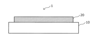
- FIG. 1 is an explanatory diagram showing a schematic configuration of a plated steel sheet according to an embodiment of the present invention
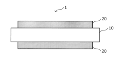
- FIG. 2 is an explanatory diagram illustrating a schematic configuration of the plated steel sheet according to the embodiment.
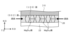
- FIG. 2 is a schematic diagram for explaining an MgZn 2 phase in a plating layer of the plated steel sheet according to the embodiment.
- FIG. 2 is an explanatory diagram for explaining peak intensities in the XRD measurement results.
- Figures 1A and 1B are explanatory diagrams that diagrammatically show an example of a plated steel sheet according to the present embodiment.
- the plated steel sheet 1 has a base steel sheet 10 and a plating layer 20 located on at least a portion of the surface of the steel sheet 10. Furthermore, the plating layer 20 does not have to be present on only one surface of the steel sheet 10 as shown in FIG. 1A, but may be present on both surfaces of the steel sheet 10 as shown diagrammatically in FIG. 1B.
- the dimensions, components, structure, and mechanical properties of the steel sheet 10 used as the base material of the plated steel sheet 1 according to the present embodiment are not particularly limited.
- various steel sheets can be used depending on the mechanical strength (e.g., tensile strength) required for the plated steel sheet 1.
- steel sheets 10 examples include various Al-killed steels, ultra-low carbon steels containing Ti, Nb, etc., high-strength steels in which the ultra-low carbon steels further contain strengthening elements such as P, Si, and Mn, and various steel sheets containing various other components (Cr, N, Cu, B, Ni, Mg, Ca, V, Co, Zn, As, Y, Zr, Mo, Sn, Sb, Ta, W, Pb, Bi, REM, etc.).
- various other components Cr, N, Cu, B, Ni, Mg, Ca, V, Co, Zn, As, Y, Zr, Mo, Sn, Sb, Ta, W, Pb, Bi, REM, etc.
- the thickness of the steel sheet 10 is not particularly limited and may be set appropriately depending on the mechanical strength, etc., required for the plated steel sheet 1.
- a steel plate having a tensile strength of 780 MPa or more is used as the steel plate 10.
- Such a steel plate 10 is suitable as a base steel plate for forming the plating layer 20 according to this embodiment. More preferably, a steel plate having a tensile strength of 980 MPa or more is used as the steel plate 10.
- the chemical composition of plating layer 20 contains, by mass%, Al: 0.50 to 4.50% or less, Mg: 0.50 to less than 3.00%, Fe: 0.01 to 15.00%, with the balance being 5.0000 mass% or more of Zn and impurities.
- the contents of Al, Mg, and Fe are within the above ranges, and the total of these contents is less than 95.0000 mass%, with the balance being 5.0000 mass% or more of Zn and impurities.
- the chemical composition of the plating layer 20 contains, in mass%, Al: 0.50 to 4.50% or less, Mg: 0.50 to less than 3.00%, Fe: 0.01 to 15.00%, and further contains one or more elements selected from the group consisting of element group A, element group B, element group C, element group D, element group E, element group F, and element group G below, with the balance being 5.0000 mass% or more of Zn and impurities.
- the contents of Al, Mg, and Fe are within the above ranges, and the total content of Al, Mg, Fe, and element group A to element group G is less than 95.0000 mass%, with the balance being 5.0000 mass% or more of Zn and impurities.
- Fe may be intentionally added to the plating bath used in producing the plating layer 20, within a range that does not impair the effects of the present invention.
- the Fe content in the plating bath is high, high-melting-point intermetallic compounds of Fe and Al are formed in the plating bath, and such high-melting-point intermetallic compounds tend to adhere to the plating layer 20 as dross, significantly reducing the appearance quality, which is not preferable.
- the Fe content in the plating bath is adjusted so that the Fe content in the plating layer 20 is 15.00 mass% or less.
- the Fe content in the plating layer 20 is more preferably 10.00 mass% or less.
- an element group B that may be contained in the plating layer 20 will be described. At least one element in the element group B shown below is an element that may be contained in the plating layer 20 in place of a portion of the remaining Zn.
- element group B one or more selected from the group consisting of Sb: more than 0% and 0.5000% or less, Pb: more than 0% and 0.5000% or less, and Sr: more than 0% and 0.5000% or less
- Such an effect of improving the design is expressed when the content of at least one of Sb, Pb, and Sr is 0.0500 mass% or more. Therefore, when at least one of Sb, Pb, and Sr is contained in the plating layer 20, it is preferable that the content of these elements is independently set to 0.0500 mass% or more.
- the plating layer 20 Since it is possible that the plating layer 20 according to this embodiment does not contain Mo, the lower limit of the Mo content is 0 mass%. On the other hand, when Mo is contained in the plating layer 20, it is possible to further improve the corrosion resistance. Such an effect of improving the corrosion resistance is realized when the Mo content is 0.0100 mass% or more. Therefore, when Mo is contained, the content is preferably 0.0100 mass% or more.
- the plating layer 20 does not contain In, Bi, and Sn, the lower limit of their contents is 0 mass%.
- Bi, and Sn are elements that increase the Mg dissolution rate when the plating layer 20 containing In, Bi, and Sn is placed in a corrosive environment. When the Mg dissolution rate increases, Mg ions are supplied to the exposed parts of the steel sheet 10, and the corrosion resistance is further improved. From this viewpoint, when In, Bi, and Sn are contained, their contents are preferably 0.00500 mass% or more.
- the La, Ce, and Y contents in the plating bath for producing the plating layer 20 are adjusted from the viewpoint of plating operability, so that the La, Ce, and Y contents are each independently 0.5000 mass% or less.
- the La, Ce, and Y contents are preferably each independently 0.1000 mass% or less.
- the plating layer 20 since the plating layer 20 according to the present embodiment may not contain B, the lower limit of the content is 0 mass%.
- B when B is contained in the plating layer 20, it has the effect of further suppressing LME. This is presumed to be because when B is contained in the plating layer 20, it combines with at least one of Zn, Al, Mg, and Ca to form various intermetallic compounds.
- the presence of B in the plating layer 20 is thought to have the effect of further suppressing LME of the steel sheet 10 by diffusing from the plating layer 20 to the steel sheet 10 and strengthening the grain boundaries.
- the chemical components of the plating layer 20 can be measured using ICP-AES (Inductively Coupled Plasma Atomic Emission Spectrometry) or ICP-MS (Inductively Coupled Plasma Mass Spectrometry).
- ICP-AES Inductively Coupled Plasma Atomic Emission Spectrometry
- ICP-MS Inductively Coupled Plasma Mass Spectrometry
- ICP-AES Inductively Coupled Plasma Atomic Emission Spectrometry
- ICP-MS Inductively Coupled Plasma Mass Spectrometry
- the plating layer 20 has the above-mentioned chemical composition, and is formed through a manufacturing method described in detail below, and contains metal phases and intermetallic compound phases (metal structures) such as ⁇ Zn phase, ⁇ phase, ⁇ phase, MgZn2 phase, Mg2Zn3 phase, and MgZn phase.
- metal phases and intermetallic compound phases metal structures such as ⁇ Zn phase, ⁇ phase, ⁇ phase, MgZn2 phase, Mg2Zn3 phase, and MgZn phase.
- the plating layer 20 may further contain, in addition to the above-mentioned metal structures, the plating layer 20 may contain metal structures such as Al-Si-Ca phase, Al-Si-Ca-Fe phase, Mg2Si phase, and Mg2Sn phase.
- the plating layer 20 according to the present embodiment exhibits properties of suppressing the occurrence of LME and excellent corrosion resistance.
- the type of metal structure of the plating layer 20 can be identified by observing the surface of the plating layer 20 with a scanning electron microscope (SEM). That is, the solidification structure of the plating layer 20 is observed with an SEM, and the type of metal structure can be identified from the point analysis results of an SEM-EPMA (Electron Probe Micro Analyzer) in the observation field and the morphology of the crystal phase in the backscattered electron image.
- SEM-EPMA Electro Probe Micro Analyzer
- polishing may be performed to remove the chemical conversion coating or the like.
- polishing polishing is performed so that 80% or more of the plating layer thickness remains, and the surface is mirror-finished before SEM observation to determine the surface structure.
- an analytical device such as JXA-8500 manufactured by JEOL Ltd. is used, and five arbitrary observation positions are used, with the size of the observation area per position being 40 ⁇ m ⁇ 40 ⁇ m.
- the range is observed at an acceleration voltage of 15.0 kV, an irradiation current of 5.0 ⁇ 10 ⁇ 7 A, an irradiation time of 50 milliseconds, and a magnification of 4000 times. After acquiring a backscattered electron image of the range of interest under these conditions, a point analysis of each metal structure is performed using the contrast of the backscattered electron image.
- the present inventors focused on the MgZn 2 phase among the above-mentioned metal structures.
- the MgZn 2 phase is a phase of an intermetallic compound of Mg and Zn formed in the plating layer 20 according to the present embodiment.
- the MgZn 2 phase is contained as a phase that improves corrosion resistance and weldability. That is, the MgZn 2 phase has higher insulation and corrosion resistance than the Zn phase.
- the MgZn 2 phase has a lower corrosion potential and is excellent in sacrificial corrosion resistance compared to the Zn phase, improving the corrosion resistance around the welded portion.
- the MgZn 2 phase densifies the corrosion products after welding and suppresses red rust.
- the plating layer 20 is suppressed from burning during welding.
- the crystal orientation of the MgZn 2 phase is further controlled to have a columnar orientation, suppressing paint film blistering.
- Fig. 2 is a schematic diagram showing an overview of the prismatic orientation of the MgZn 2 phase according to this embodiment and an overview of coating blister that may occur in the plated steel sheet 1.
- the MgZn 2 phase has a hexagonal crystal structure, and three unit cells of a square columnar structure are gathered together to form a hexagonal columnar structure as shown in FIG. 2.
- the surface shown by the hexagon is the (002) surface of the MgZn 2 phase
- one of the columnar surfaces perpendicular to the (002) surface of the MgZn 2 phase is the (100) surface of the MgZn 2 phase.
- the size of the MgZn 2 phase shown in FIG. 2 is for convenience and does not mean that a single crystal of such a size is formed.
- the (100) plane of the MgZn 2 phase is oriented so as to be a plane perpendicular to the ND (Normal Direction) axis normal to the RD-TD plane (i.e., a plane parallel to the RD-TD plane) in a material coordinate system defined by the RD (Rolling Direction) axis and the TD (Transversal Direction: direction perpendicular to the rolling direction, width direction) axis when a pole measurement is performed by X-ray diffraction (XRD).
- ND Normal Direction
- RD-TD Normal Direction
- TD Transversal Direction: direction perpendicular to the rolling direction, width direction
- the (100) plane of the MgZn 2 phase is a crystal plane perpendicular to the (002) plane of the MgZn 2 phase. Therefore, by orienting the (100) plane of the MgZn 2 phase so as to be perpendicular to the ND axis, the (002) plane of the MgZn 2 phase is oriented so as to be parallel to the ND axis (i.e., perpendicular to the RD-TD plane). Note that the (002) plane of the MgZn 2 phase only needs to be parallel to the ND axis, and the orientation on the RD-TD plane (the orientation relative to the RD axis or TD axis) is not particularly limited.
- the plated steel sheet 1 according to this embodiment is painted on the plating layer 20 to form the coating film 30.
- Corrosion of the plating layer 20 i.e., under-film corrosion
- under-film corrosion may occur under the coating film 30 in the heat-affected zone.
- the thick arrow (corrosion) in Figure 2 under-film corrosion progresses in a direction perpendicular to the ND axis. The progress of such under-film corrosion changes the thickness of the plating layer 20, and the change in the thickness of the coating film 30 formed on the plating layer 20 causes paint blistering.
- the inventors have verified under-film corrosion and have newly discovered that when under-film corrosion progresses in the MgZn2 phase, the progress of under-film corrosion is suppressed in the direction perpendicular to the (002) plane of the MgZn2 phase more than in the direction perpendicular to other crystal planes of the MgZn2 phase. This is believed to be because the (002) plane is a dense plane of the MgZn2 crystal.
- the inventors came up with the idea that the progression of under-film corrosion can be suppressed and the blistering of the coating can be suppressed by orienting the (002) plane of the MgZn 2 phase perpendicular to the progression direction of under-film corrosion.
- the plating layer 20 contains MgZn 2 phase whose (002) plane is perpendicular to any progression direction of under-film corrosion.
- the orientation of the MgZn 2 phase so that the (002) plane of the MgZn 2 phase is perpendicular to the progression direction of under-film corrosion is referred to as columnar orientation in this specification.
- the success or failure of the prismatic orientation of the MgZn 2 phase can be determined by XRD based on whether the following conditions are satisfied: That is, when the surface of the plating layer 20 according to the present embodiment is measured by a commercially available wide-angle X-ray diffraction device, if the peak intensity ratio I 100 /I 002 of the peak intensity I 100 corresponding to the (100) plane of the MgZn 2 phase to the peak intensity I 002 corresponding to the (002) plane of the MgZn 2 phase is 2.50 or more in the obtained measurement result, it can be determined that the prismatic orientation of the (002) plane as shown in FIG. 2 is achieved.
- the intensity of the peaks belonging to each plane direction is calculated by subtracting the intensity Ip of the peak of interest from the intensity Ib of the baseline in the XRD spectrum as shown in FIG. 3 (i.e., " Ip - Ib ").
- the upper limit of the peak intensity ratio I 100 /I 002 is not particularly limited, and it is understood that the higher the ratio, the more preferable the alignment state is.
- the peak intensity ratio I 100 /I 002 theoretically exhibits a value of 1.75 ⁇ 0.02.
- a test piece of a size that can be taken from a member is prepared from the plated steel sheet 1 whose tensile strength is to be measured, among the test pieces specified in JIS Z 2201 (2011), and the tensile strength of the test piece is measured by the method specified in JIS Z 2241 (2011).
- the carbon (C) concentration at the surface of the plated steel sheet In the plated steel sheet 1 according to this embodiment, measurement is performed in the depth direction starting from the surface of the plating layer 20 by glow discharge optical emission spectrometry (GDS), and a depth profile relating to the distribution of Zn, Fe, and C is measured.
- GDS glow discharge optical emission spectrometry
- GDS measurements can be performed using a commercially available glow discharge optical emission analyzer under the following conditions:
- the position of the interface between the plating layer 20 and the steel sheet 10 is determined. More specifically, in the obtained depth profile of the distribution of Zn and Fe, the depth at which the curve showing the Zn intensity and the curve showing the Fe intensity intersect is determined to be the interface between the plating layer 20 and the steel sheet 10. Next, in the depth profile of the distribution of C, the transition of the C concentration is confirmed starting from the above-mentioned interface. In other words, the C concentration of interest below can be said to be the C concentration in the part of the steel sheet 10 adjacent to the interface between the plating layer 20 and the steel sheet 10.
- the depth at which the C concentration is 0.05% or less by mass is 10 ⁇ m or more from the interface.
- the depth at which the C concentration is 0.05% or less by mass is preferably 15 ⁇ m or more.
- the C concentration in the surface layer of the steel sheet 10 is adjusted to a desired value by controlling the conditions of the decarburization annealing performed on the steel sheet 10. Such decarburization annealing is performed as necessary during the production of the plated steel sheet.
- the plated steel sheet 1 according to this embodiment has been described in detail above with reference to Figures 1A to 3.
- the plated steel sheet 1 according to this embodiment as described above can be suitably used, for example, as a material for automobile suspension parts.
- the plated steel sheet 1 according to this embodiment may further have one or more layers of various coatings on the above-mentioned plating layer 20.
- coatings include a chromate coating, a phosphate coating, a chromate-free coating, an organic resin coating, etc.
- the plated steel sheet 1 is manufactured by using the above-described steel sheet 10 as a base material, imparting strain to the surface of the steel sheet 10 through a heavy grinding process, and then forming a plating layer 20 on the strained surface.
- the surface of the steel sheet 10 is ground with a heavy grinding brush to impart strain to the surface, thereby forming nucleation sites for growing the MgZn 2 phase to have a columnar orientation on the surface of the steel sheet 10. Thereafter, a specific heat treatment is performed on the plating layer 20 formed on the surface of the steel sheet 10, so that the MgZn 2 phase grows to have a columnar orientation.
- imparting strain to the surface promotes Zn-Fe alloying during welding of the plated steel sheet 1, making it possible to further suppress LME.
- hot-dip plating In addition to hot-dip plating, methods such as thermal spraying, cold spraying, sputtering, vapor deposition, and electroplating can be used to form the plating layer 20. However, in terms of cost, hot-dip plating is the most preferable method for forming a plating layer of a thickness generally used in automobiles, etc.
- the obtained plated steel sheet (steel sheet 10 having a plating layer 20) is subjected to a specific heat treatment process as described below, thereby manufacturing the plated steel sheet 1 according to this embodiment.
- the steel sheet 10 used as the base material is rolled by the Sendzimir method to the desired thickness, then wound into a coil and installed in the hot-dip plating line.
- the steel sheet 10 is continuously passed through while being unwound from the coil.
- a heavy grinding brush provided at a predetermined position is used to impart strain to the surface of the steel sheet.
- the steel sheet is heated and reduced at 700 to 900°C for more than 0 sec and 300 sec or less in an atmosphere of N2- (1 to 10)% H2 gas and a dew point of -60 to 10°C in an environment where oxidation is unlikely to occur, for example, with an oxygen concentration of 20 ppm or less, and then air-cooled with N2 gas to a bath temperature of about +20°C of the subsequent plating bath and immersed in the plating bath.
- strain is imparted to the steel sheet before annealing, but even if at least a part of the imparted strain is released by annealing, the recrystallization occurring in the steel surface layer during annealing is promoted, thereby making the Fe grain size fine and functioning as a nucleation site during solidification of the plating layer in the subsequent plating process.
- decarburization of the surface of the steel sheet 10 may be performed.
- the dew point in the N 2 -(1 to 10)% H 2 atmospheric gas in the heating and reducing treatment step is set to -10 to 10°C.
- the depth at which the C concentration is 0.05% or less in mass % can be set to 10 ⁇ m or more in the measurement results by GDS in the depth direction of the manufactured plated steel sheet 1.
- the dew point in the N 2 -(1 to 10)% H 2 atmospheric gas in the heating and reducing treatment step may be set to -30 to -70°C.
- a plating alloy in a molten state having the above-mentioned chemical components is prepared in the plating bath.
- the bath temperature of the plating bath is set to be equal to or higher than the melting point of the plating alloy (e.g., about 460 to 660°C).
- the bath temperature of the plating bath is determined to be equal to or higher than the theoretical temperature (e.g., about theoretical temperature + 40°C) based on the "theoretical temperature at which the MgZn 2 phase nucleates" (hereinafter also referred to as the theoretical temperature) as described below, while paying attention to the melting point of the plating alloy.
- the alloying materials When preparing the plating alloy material, it is preferable to use pure metals (with a purity of 99% or more) as the alloying materials. First, a predetermined amount of alloying metals is mixed so as to obtain the above-mentioned plating layer composition, and then completely melted to obtain an alloy using a high-frequency induction furnace or arc furnace under vacuum or inert gas replacement conditions. Next, the alloy mixed with the predetermined components (the above-mentioned plating layer composition) is melted in the atmosphere, and the resulting molten material is used as the plating bath.
- the molten plating alloy located on the steel sheet having the surface strained by the heavy grinding brush is subjected to the first and second cooling steps as described below, so that the molten plating alloy becomes the plating layer 20 and the MgZn 2 phase is grown to have a columnar orientation.
- the first and second cooling steps are described in detail below.
- an alloying heat treatment step for example, a heat treatment step involving heating to a sheet temperature of about 480 to 550°C
- the columnar orientation of the MgZn 2 phase controlled by the first cooling step and the second cooling step is lost, and as a result, the effect of suppressing paint blistering as focused on in this embodiment cannot be obtained. From this viewpoint, it is important not to perform a heat treatment step after the second cooling step.
- the relationship between the surface temperature of the plating layer and the average temperature of the entire plating layer may be obtained by a simulation that performs a heat conduction analysis. Specifically, the surface temperature of the plating layer and the average temperature of the entire plating layer are obtained based on various manufacturing conditions such as the preheating temperature of the steel sheet, the temperature of the plating bath, the pulling speed of the steel sheet from the plating bath, the sheet thickness of the steel sheet, the thickness of the plating layer, the amount of heat exchanged between the plating layer and the manufacturing equipment, and the amount of heat dissipated from the plating layer. The relationship between the surface temperature of the plating layer and the average temperature of the entire plating layer can then be obtained using the obtained results.
- chromate treatment There are various types of chromate treatment, including electrolytic chromate treatment, which forms a chromate film by electrolysis, reactive chromate treatment, which uses a reaction with the material to form a film and then washes away excess treatment liquid, and application-type chromate treatment, which applies a treatment liquid and then dries it without rinsing to form a film. Any type of chromate treatment may be used.
- the plated steel sheet according to the present invention will be specifically described with reference to examples and comparative examples. Note that the examples shown below are merely examples of the plated steel sheet according to the present invention, and the plated steel sheet according to the present invention is not limited to the examples shown below.
- the test piece After immersion in the plating bath, the test piece was pulled up at a pulling speed of 20 to 200 mm/sec. During pulling, the desired plating adhesion amount was controlled by N2 wiping gas. In the following examples and comparative examples, the plating adhesion amount was controlled so that the plating layer adhesion amount per one side of the test piece after drying was 40 to 120 g/ m2 .
- the test piece After pulling the test piece out of the plating bath, the test piece was cooled from the plating bath temperature to room temperature under the conditions shown in Table 1 below.
- the second cooling step was started immediately after the first cooling step was completed (i.e., the interval from the completion of the first cooling step to the start of the second cooling step was set to 0.2 seconds or less).
- the switching temperature for switching between the first cooling step and the second cooling step was set to the respective theoretical temperatures in the examples and comparative examples except for Comparative Examples 31 and 32. In Comparative Examples 31 and 32, a temperature different from the theoretical temperature was set as the switching temperature.
- the excessive Al content inhibited the alloying reaction between the Zn in the coating layer and the base steel during welding, causing the liquid phase Zn-Mg to come into contact with the base steel, making it impossible to suppress LME.
- the excessive Al content caused ⁇ primary crystals to crystallize in the coating layer in the non-heat-affected zone, inhibiting the columnar orientation of the MgZn2 phase, making it impossible to suppress blistering of the coating film.
- the plated steel sheet wherein, in a measurement result obtained by measuring the plating layer by an X-ray diffraction method, a peak intensity ratio I 100 /I 002 of a peak intensity I 100 corresponding to a ( 100 ) plane of the MgZn 2 phase to a peak intensity I 002 corresponding to a ( 002 ) plane is 2.50 or more.
- element group D one or more elements selected from the group consisting of In: more than 0% and 1.0000% or less, Bi: more than 0% and 1.0000% or less, and Sn: more than 0% and 1.0000% or less
- element group E one or more elements selected from the group consisting of Zr: more than 0% and 1.0000% or less, Ag: more than 0% and 1.0000% or less, and Li: more than 0% and 1.0000% or less
- element group F one or more elements selected from the group consisting of La: more than 0% and 0.5000% or less, Ce: more than 0% and 0.5000% or less, and Y: more than 0.5000% or less
- element group G B: more than 0% and 0.5000% or less
Landscapes
- Chemical & Material Sciences (AREA)
- Engineering & Computer Science (AREA)
- Materials Engineering (AREA)
- Mechanical Engineering (AREA)
- Metallurgy (AREA)
- Organic Chemistry (AREA)
- Chemical Kinetics & Catalysis (AREA)
- Thermal Sciences (AREA)
- Crystallography & Structural Chemistry (AREA)
- Physics & Mathematics (AREA)
- General Chemical & Material Sciences (AREA)
- Coating With Molten Metal (AREA)
- Electroplating Methods And Accessories (AREA)
- Analysing Materials By The Use Of Radiation (AREA)
Abstract
Description
かかる知見に基づき完成された本発明の要旨は、以下の通りである。
Al:0.50~4.50以下、
Mg:0.50~3.00%未満、
Fe:0.01~15.00%
を含有し、選択的に、下記元素群A、元素群B、元素群C、元素群D、元素群E、元素群F、及び、元素群Gからなる群より選択される1種又は2種以上を含有し、残部が、5.0000質量%以上のZnと、不純物と、からなる化学組成を有するめっき層を有し、
前記めっき層をX線回折法により測定することで得られる測定結果において、MgZn2相の(100)面に対応するピークの強度I100と(002)面に対応するピークの強度I002のピーク強度比I100/I002が、2.50以上である、めっき鋼板。
[元素群A]:Si:0%超2.00%以下、及び、Ca:0%超2.00%以下からなる群より選択される1種又は2種
[元素群B]:Sb:0%超0.5000%以下、Pb:0%超0.5000%以下、及び、Sr:0%超0.5000%以下からなる群より選択される1種又は2種以上
[元素群C]:Co:0%超1.0000%以下、V:0%超1.0000%以下、Cu:0%超1.0000%以下、Ti:0%超1.0000%以下、Cr:0%超1.0000%以下、Nb:0%超1.0000%以下、Ni:0%超1.0000%以下、Mn:0%超1.0000%以下、及び、Mo:0%超1.0000%以下からなる群より選択される1種又は2種以上
[元素群D]:In:0%超1.0000%以下、Bi:0%超1.0000%以下、及び、Sn:0%超1.0000%以下からなる群より選択される1種又は2種以上
[元素群E]:Zr:0%超1.0000%以下、Ag:0%超1.0000%以下、及び、Li:0%超1.0000%以下からなる群より選択される1種又は2種以上
[元素群F]:La:0%超0.5000%以下、Ce:0%超0.5000%以下、及び、Y:0%超0.5000%以下からなる群より選択される1種又は2種以上
[元素群G]:B:0%超0.5000%以下
(2)前記元素群Aを含有する化学組成を有する、上記(1)に記載のめっき鋼板。
(3)前記元素群Bを含有する化学組成を有する、上記(1)に記載のめっき鋼板。
(4)前記元素群Cを含有する化学組成を有する、上記(1)に記載のめっき鋼板。
(5)前記元素群Dを含有する化学組成を有する、上記(1)に記載のめっき鋼板。
(6)前記元素群Eを含有する化学組成を有する、上記(1)に記載のめっき鋼板。
(7)前記元素群Fを含有する化学組成を有する、上記(1)に記載のめっき鋼板。
(8)前記元素群Gを含有する化学組成を有する、上記(1)に記載のめっき鋼板。
(9)前記鋼板は、引張強度が780MPa級以上である、上記(1)~(8)の何れか1つに記載のめっき鋼板。
(10)前記ピーク強度比I100/I002が、5.00以上である、上記(1)~(8)の何れか1つに記載のめっき鋼板。
(11)前記ピーク強度比I100/I002が、5.00以上である、上記(9)に記載のめっき鋼板。
(12)前記ピーク強度比I100/I002が、10.00以上である、上記(10)に記載のめっき鋼板。
(13)前記ピーク強度比I100/I002が、10.00以上である、上記(11)に記載のめっき鋼板。
(14)前記めっき鋼板の深さ方向におけるグロー放電発光分析法により測定することで得られる測定結果において、C濃度が質量%で0.05%以下である深さが10μm以上である、上記(1)~(8)の何れか1つに記載のめっき鋼板。
(15)前記めっき鋼板の深さ方向におけるグロー放電発光分析法により測定することで得られる測定結果において、C濃度が質量%で0.05%以下である深さが10μm以上である、上記(9)に記載のめっき鋼板。
(16)前記めっき鋼板の深さ方向におけるグロー放電発光分析法により測定することで得られる測定結果において、C濃度が質量%で0.05%以下である深さが10μm以上である、上記(10)に記載のめっき鋼板。
(17)前記めっき鋼板の深さ方向におけるグロー放電発光分析法により測定することで得られる測定結果において、C濃度が質量%で0.05%以下である深さが10μm以上である、上記(11)に記載のめっき鋼板。
(18)前記めっき鋼板の深さ方向におけるグロー放電発光分析法により測定することで得られる測定結果において、C濃度が質量%で0.05%以下である深さが10μm以上である、上記(12)に記載のめっき鋼板。
(19)前記めっき鋼板の深さ方向におけるグロー放電発光分析法により測定することで得られる測定結果において、C濃度が質量%で0.05%以下である深さが10μm以上である、上記(13)に記載のめっき鋼板。
まず、図1A及び図1Bを参照しながら、本発明の実施形態に係るめっき鋼板の全体的な構成について説明する。図1A及び図1Bは、本実施形態に係るめっき鋼板の一例を模式的に示した説明図である。
本実施形態に係るめっき鋼板1の母材として用いられる鋼板10の寸法、成分、組織、機械的特性は、ある態様によれば、特に限定されるものではない。例えば、めっき鋼板1に求められる機械的強度(例えば、引張強度)等に応じて、各種の鋼板を用いることが可能である。このような鋼板10として、例えば、各種のAlキルド鋼、Ti、Nb等を含有させた極低炭素鋼、極低炭素鋼にP、Si、Mn等の強化元素を更に含有させた高強度鋼、その他各種の成分(Cr、N、Cu、B、Ni、Mg、Ca、V、Co、Zn、As、Y、Zr、Mo、Sn、Sb、Ta、W、Pb、Bi、REM等)を含有した種々の鋼板等を挙げることができる。
めっき層20は、図1A及び図1Bに模式的に示したように、鋼板10の表面上に設けられ、鋼板10の表面の全体にわたって設けられることがより好ましい。以下では、まず、かかるめっき層20の化学組成について、詳細に説明する。
本実施形態に係るめっき層20の化学組成は、ある態様によれば、質量%で、Al:0.50~4.50%以下、Mg:0.50~3.00%未満、Fe:0.01~15.00を含有し、残部が、5.0000質量%以上のZnと、不純物と、からなる化学組成を有する。つまり、本実施形態に係るめっき層20の化学組成において、Al、Mg、Feの含有量が上記の範囲内で、かつ、これら含有量の合計が95.0000質量%未満であり、残部は、5.0000質量%以上のZnと、不純物である。
[元素群B]:Sb:0%超0.5000%以下、Pb:0%超0.5000%以下、及び、Sr:0%超0.5000%以下からなる群より選択される1種又は2種以上
[元素群C]:Cu:0%超1.0000%以下、Ti:0%超1.0000%以下、Cr:0%超1.0000%以下、Nb:0%超1.0000%以下、Ni:0%超1.0000%以下、Mn:0%超1.0000%以下、及び、Mo:0%超1.0000%以下からなる群より選択される1種又は2種以上
[元素群D]:In:0%超1.0000%以下、Bi:0%超1.0000%以下、及び、Sn:0%超1.0000%以下からなる群より選択される1種又は2種以上
[元素群E]:Zr:0%超1.0000%以下、Ag:0%超1.0000%以下、及び、Li:0%超1.0000%以下からなる群より選択される1種又は2種以上
[元素群F]:La:0%超0.5000%以下、Ce:0%超0.5000%以下、及び、Y:0%超0.5000%以下からなる群より選択される1種又は2種以上
[元素群G]:B:0%超0.5000%以下
Alは、本実施形態に係るめっき層20の主たる金属組織(Zn-Al-Mg系金属組織)を構成するために必要な元素であり、めっき鋼板として、溶接熱影響部となる部位の耐食性、及び、非溶接部となる部位の耐食性を確保するうえで、一定以上含有される。めっき層20におけるAl含有量が0.50質量%未満である場合には、上記のような溶接熱影響部及び非溶接部となる部位の耐食性を担保することができない。そのため、本実施形態に係るめっき層20において、Al含有量は、0.50質量%以上である。Al含有量は、好ましくは1.00質量%以上であり、より好ましくは1.50質量%以上である。Al含有量が、上記のような範囲となることで、めっき鋼板1の耐食性を担保することが可能となる。
Mgは、本実施形態に係るめっき層20の主たる金属組織(Zn-Al-Mg系金属組織)を構成するために必要な元素であり、特に、後述するMgZn2相を形成するために必要な元素である。すなわち、Mgは、めっき鋼板として、溶接熱影響部となる部位の耐食性、及び、非溶接部となる部位の耐食性を確保するうえで、一定以上含有される。そのため、本実施形態に係るめっき層20において、Mg含有量は、0.50質量%以上である。Mg含有量は、好ましくは1.00質量%以上であり、より好ましくは1.50質量%以上である。めっき層20におけるMgが0.50質量%未満となる場合には、非溶接部となる部位の耐食性が十分でなく、また後述するMgZn2相の柱面配向が十分でない場合がある。Mg含有量が、上記のような範囲となることで、めっき鋼板1の耐食性を担保し、後述するMgZn2相を形成することが可能となる。
めっき層20には、母材である鋼板10から、鋼板を構成する元素が混入することがある。特に、溶融めっき法では、鋼板10とめっき層20との間での固液反応による元素の相互拡散によって、鋼板10を構成する元素がめっき層20へ混入し易くなる。このような元素の混入により、めっき層20中には、一定量のFeが含有され、その含有量は、0.01質量%以上となることが一般的である。上記相互拡散が促進されれば、鋼板10とめっき層20との密着性が向上する。鋼板10とめっき層20との密着性の向上という観点からは、めっき層20中のFe含有量は、0.20質量%以上であることが好ましい。
本実施形態に係るめっき層20の別の態様において、めっき層20が含有しうる元素群Aについて説明する。以下に示す元素群Aの少なくとも何れかの元素は、残部のZnの一部に換えて、めっき層20中に含有されうる元素である。
[元素群A]:Si:0%超2.00%以下、及び、Ca:0%超2.00%以下からなる群より選択される1種又は2種
本実施形態に係るめっき層20においてSiを含有しない場合も考えうるため、その含有量の下限は、0質量%である。一方、Siは、めっき層と鋼板の界面に形成するFe-Al系金属間化合物相の過剰な成長を抑制し、めっき層と鋼板の密着性を更に向上させることが可能な元素である。めっき層20中にSiを含有させる場合、Fe-Al系金属間化合物相の過剰な成長を抑制するために、Siの含有量は、0.05質量%以上が好ましく、0.20質量%以上がより好ましい。
本実施形態に係るめっき層20においてCaを含有しない場合も考えうるため、その含有量の下限は、0質量%である。一方、Caは、めっき層20中に含有されると、Al及びZnと金属間化合物相を形成する。更に、めっき層20中にCaと共にSiが含有される場合、CaはSiと金属間化合物を形成する。これらの金属間化合物は、融点が高く、安定な構造であるため、めっき鋼板の溶接時のLMEを更に抑制することが可能となる。めっき層20中にCaを含有させる場合、かかる溶接時のLMEの抑制効果は、Ca含有量を0.01質量%以上とすることで発現される。めっき層20中におけるCa含有量は、より好ましくは0.10質量%以上である。
続いて、本実施形態に係るめっき層20の別の態様において、めっき層20が含有しうる元素群Bについて説明する。以下に示す元素群Bの少なくとも何れかの元素は、残部のZnの一部に換えて、めっき層20中に含有されうる元素である。
[元素群B]:Sb:0%超0.5000%以下、Pb:0%超0.5000%以下、及び、Sr:0%超0.5000%以下からなる群より選択される1種又は2種以上
[Pb:0~0.5000質量%]
[Sr:0~0.5000質量%]
本実施形態に係るめっき層20においてSb、Pb、Srを含有しない場合も考えうるため、これら元素の含有量の下限は、0質量%である。一方、Sb、Pb、Srの少なくとも何れかがめっき層20中に含有されると、めっき層20の表面にスパングルが形成されて、金属光沢の向上を図ることが可能となる。そのため、めっき鋼板の更なる意匠性向上という観点から、Sb、Pb、Srの少なくとも何れかがめっき層20中に含有されることが好ましい。かかる意匠性向上効果は、Sb、Pb、Srの少なくとも何れかの含有量が0.0500質量%以上となった場合に発現される。そのため、Sb、Pb、Srの少なくとも何れかをめっき層20に含有させる場合には、これら元素の含有量は、それぞれ独立に、0.0500質量%以上とされることが好ましい。
続いて、本実施形態に係るめっき層20の別の態様において、めっき層20が含有しうる元素群Cについて説明する。以下に示す元素群Cの少なくとも何れかの元素は、残部のZnの一部に換えて、めっき層20中に含有されうる元素である。
[元素群C]:Co:0%超1.0000%以下、V:0%超1.0000%以下、Cu:0%超1.0000%以下、Ti:0%超1.0000%以下、Cr:0%超1.0000%以下、Nb:0%超1.0000%以下、Ni:0%超1.0000%以下、Mn:0%超1.0000%以下、及び、Mo:0%超1.0000%以下からなる群より選択される1種又は2種以上
[V :0~1.0000質量%]
[Cu:0~1.0000質量%]
[Ti:0~1.0000質量%]
[Cr:0~1.0000質量%]
[Nb:0~1.0000質量%]
[Ni:0~1.0000質量%]
[Mn:0~1.0000質量%]
本実施形態に係るめっき層20においてCo、V、Cu、Ti、Cr、Nb、Ni、Mnを含有しない場合も考えうるため、これら元素の含有量の下限は、0質量%である。一方、Co、V、Cu、Ti、Cr、Nb、Ni、Mnの少なくとも何れかがめっき層20中に含有されると、かかるめっき鋼板を溶接した際に、これら元素が、溶接によって生成されるFe-Al系金属組織に取り込まれ、形成される溶接部の耐食性を更に向上させることが可能となる。かかる溶接部耐食性の向上効果は、めっき層20中のCo、V、Cu、Ti、Cr、Nb、Ni、Mnの少なくとも何れかの含有量が0.0050質量%以上となった場合に発現される。そのため、Co、V、Cu、Ti、Cr、Nb、Ni、Mnの少なくとも何れかをめっき層20中に含有させる場合には、これら元素の含有量は、それぞれ独立に、0.0050質量%以上とされることが好ましい。
本実施形態に係るめっき層20においてMoを含有しない場合も考えうるため、その含有量の下限は、0質量%である。一方、Moがめっき層20中に含有されると、耐食性を更に向上させることが可能となる。かかる耐食性の向上効果は、Moの含有量が0.0100質量%以上となった場合に発現される。そのため、Moを含有させる場合には、その含有量は、0.0100質量%以上とすることが好ましい。
続いて、本実施形態に係るめっき層20の別の態様において、めっき層20が含有しうる元素群Dについて説明する。以下に示す元素群Dの元素は、残部のZnの一部に換えて、めっき層20中に含有されうる元素である。
[元素群D]:In:0%超1.0000%以下、Bi:0%超1.0000%以下、及び、Sn:0%超1.0000%以下からなる群より選択される1種又は2種以上
[Bi:0~1.0000質量%]
[Sn:0~1.0000質量%]
本実施形態に係るめっき層20においてIn、Bi、Snを含有しない場合も考えうるため、その含有量の下限は、0質量%である。In、Bi、Snを含むめっき層20が腐食環境に置かれた場合に、Mg溶出速度を上昇させる元素である。Mgの溶出速度が上昇すると、鋼板10が露出した部分にMgイオンが供給され、耐食性が更に向上する。かかる観点から、In、Bi、Snを含有させる場合は、その含有量を0.00500質量%以上とすることが好ましい。
続いて、本実施形態に係るめっき層20の別の態様において、めっき層20が含有しうる元素群Eについて説明する。以下に示す元素群Eの少なくとも何れかの元素は、残部のZnの一部に換えて、めっき層20中に含有されうる元素である。
[元素群E]:Zr:0%超1.0000%以下、Ag:0%超1.0000%以下、及び、Li:0%超1.0000%以下からなる群より選択される1種又は2種以上
[Ag:0~1.0000質量%]
[Li:0~1.0000質量%]
本実施形態に係るめっき層20においてZr、Ag、Liを含有しない場合も考えうるため、これら元素の含有量の下限は、0質量%である。一方、Zr、Ag、Liの少なくとも何れかがめっき層20中に含有されると、めっき操業性を更に向上させることが可能となる。かかるめっき操業性の向上効果は、めっき層20中のZr、Ag、Liの少なくとも何れかの含有量が0.0100質量%以上となった場合に発現される。そのため、Zr、Ag、Liのすくなくとも何れかを含有させる場合には、これら元素の含有量は、それぞれ独立に、0.0100質量%以上とされることが好ましい。
続いて、本実施形態に係るめっき層20の別の態様において、めっき層20が含有しうる元素群Fについて説明する。以下に示す元素群Fの少なくとも何れかの元素は、残部のZnの一部に換えて、めっき層20中に含有されうる元素である。
[元素群F]:La:0%超0.5000%以下、Ce:0%超0.5000%以下、及び、Y:0%超0.5000%以下からなる群より選択される1種又は2種以上
[Ce:0~0.5000質量%]
[Y :0~0.5000質量%]
本実施形態に係るめっき層20においてLa、Ce、Yを含有しない場合も考えうるため、これら元素の含有量の下限は、0質量%である。一方、La、Ce、Yは、Caとほぼ同等の効果を発現する元素であり、溶接時のブローホール形成をより抑制する。これは、各元素の原子半径がCaの原子半径と近いことに起因する。これらの元素がめっき層20中に含有されると、Ca位置に置換する。そのため、これらの元素は、EDS(Energy Dispersive X-ray Spectroscopy)においてCaと同位置に検出される。また、これらの元素がめっき鋼板の溶接後に酸化物となった場合においても、これら元素の酸化物はCaOと同位置で検出される。
続いて、本実施形態に係るめっき層20の別の態様において、めっき層20が含有しうる元素群Gについて説明する。以下に示す元素群Gの元素は、残部のZnの一部に換えて、めっき層20中に含有されうる元素である。
[元素群G]:B:0%超0.5000%以下
本実施形態に係るめっき層20においてBを含有しない場合も考えうるため、その含有量の下限は、0質量%である。一方、Bは、めっき層20中に含有されると、LMEをより抑制する効果がある。これは、Bがめっき層20中に含有されると、Zn、Al、Mg、Caの少なくとも何れかと化合して、様々な金属間化合物を形成するためと推察される。また、めっき層20中にBが存在することで、Bはめっき層20から鋼板10へと拡散し、粒界強化によって鋼板10のLMEをより抑制する効果があると考えられる。更に、Bに関して形成される各種の金属間化合物は、融点が極めて高いために、溶接時におけるZn燃焼の抑制にも作用していると推察される。これらの改善効果は、Bを0.05質量%以上含有させることで発現される。そのため、Bを含有させる場合には、Bの含有量は、好ましくは0.0500質量%以上である。
上記のめっき層20の化学成分は、ICP-AES(Inductively Coupled Plasma Atomic Emission Spectrometry)又はICP-MS(lnductively Coupled Plasma Mass Spectrometry)を使用して、計測することが可能である。なお、0.1質量%単位までの化学成分の分析を行う場合には、ICP-AESを用いることとし、0.1質量%未満の微量な化学成分の分析を行う場合には、ICP-MSを用いることとする。めっき鋼板を、インヒビターを加えた10%HCl水溶液に対して1分程度浸潰し、めっき層部分を剥離し、このめっき層を溶解した溶液を準備する。得られた溶液を、ICP-AES又はICP-MSによって分析して、めっき層の全体平均としての化学成分を得ることができる。
以上説明したようなめっき層20の付着量については、特に規定するものではないが、例えば、鋼板の片面当たり、15~250g/m2程度であることが好ましい。めっき層20の付着量が上記のような範囲内となることで、本実施形態に係るめっき鋼板1は、十分な耐食性を示すことが可能となる。かかる付着量を有するめっき層20の厚みは、概ね5~40μm程度となる。
続いて、以上説明したような化学組成を有するめっき層20の金属組織について、説明する。
本実施形態に係るめっき層20は、上記のような化学組成を有し、また、以下で詳述するような製造方法を経て形成されることで、ηZn相、α相、τ相、MgZn2相、Mg2Zn3相、MgZn相等の金属相や金属間化合物相(金属組織)を含有している。また、めっき層20が更に含有しうる元素によっては、上記のような金属組織に加えて、Al-Si-Ca相、Al-Si-Ca-Fe相、Mg2Si相、Mg2Sn相等の金属組織を含有しうる。本実施形態に係るめっき層20は、上記のような金属組織を有することで、LMEの発生を抑制し、耐食性にも優れるという性質を示すようになる。
・X線源:Cu管球
・電圧:40kV
・電流:150mA
・アタッチメント:サンプルチェンジャー試料台
・フィルタ:なし
・モノクロメータ:使用
本実施形態に係るめっき鋼板1の引張強度は、母材として用いた鋼板10の引張強度に依存する。したがって、ある態様によれば、本実施形態に係るめっき鋼板1の引張強度は、780MPa以上であり、別の態様によれば、980MPa以上である。めっき鋼板1の引張強度は、公知の方法で測定することができる。一例として、引張強度を測定したいめっき鋼板1からJIS Z 2201(2011)に規定されている試験片のうち、部材から採取可能な大きさの試験片を作成し、当該試験片につきJIS Z 2241(2011)に規定されている方法で引張強度を測定する。
本実施形態に係るめっき鋼板1において、めっき層20の表面を起点として深さ方向にグロー放電発光分析法(GDS:Glow Discharge Optical Emission Spectrometry)により測定し、Zn、Fe、Cの分布に関する深さプロファイルを測定する。
Arガス圧力:0.27MPa
アノード径:4mmΦ
RF(高周波)出力:30W
次に、以上説明したようなめっき鋼板1の製造方法の一例を説明する。本実施形態に係るめっき鋼板1は、上記のような鋼板10を母材として、かかる鋼板10の表面に対して、重研削の工程によりひずみを付与した後に、ひずみの付与された表面に対してめっき層20を形成することで製造される。
ブラシ種 B:株式会社ホタニ製 M-33
得られた試験片から、150mm×50mmの大きさに切り出したものを第1鋼板とし、150mm×30mmの大きさに切り出したものを第2鋼板とした。これら鋼板の長辺側を重ね合わせて、アーク溶接、又は、レーザー溶接により溶接した(重ね隈肉溶接)。
溶接電流:250A、溶接電圧:26.4V、溶接速度:100cm/min
溶接ガス:20%CO2+Ar、ガス流量:20L/min
溶接ワイヤー:YGW16 日鉄溶接工業株式会社製 φ1.2mm
(C:0.1質量%、Si:0.80質量%、Mn:1.5質量%、P:0.015質量%、S:0.008質量%、Cu:0.36質量%)
溶接トーチの傾斜角:45°
重ね代:10mm
鋼板サイズ:上板側(第1鋼板)150×50mm、下板側(第2鋼板)150×30mm
板隙:0mm
出力:7kW、溶接速度:400cm/min、前進・後進角:0°
鋼板サイズ:上板側(第1鋼板)150×50mm、下板側(第2鋼板)150×30mm
重ね代:50mm
板隙:0mm
評点「AAA」:塗膜膨れ幅が、1.8mm以下
「AA」:塗膜膨れ幅が、1.8mm超3.0mm以下
「A」:塗膜膨れ幅が、3.0mm超4.0mm以下
「B」:塗膜膨れ幅が、5.0mm超
得られた試験片の耐LME性については、熱間引張試験により評価を行った。より詳細には、得られた試験片と、めっきを施していない鋼板と、の双方について、昇温速度100℃/secで900℃まで昇温し、900℃で1秒保持した後、750℃まで冷却し、750℃でストローク速度10mm/secで引張試験を実施した。これにより、めっきを施していない鋼板と、試験片の双方とで、応力-ストローク曲線を取得した。その後、得られた応力-ストローク曲線から、それぞれ、応力×ストローク値(応力-ストローク曲線の面積)を算出し、評価値(%)={(試験片の応力×ストローク値)/(めっきを施していない鋼板の応力×ストローク値)×100}について、以下の評価基準に基づき、評価を行った。
≪評価基準≫
評点「AA」:評価値95%以上
「A」:評価値85%以上95%未満
「B」:評価値85%未満

(1)鋼板の表面の少なくとも一部に、質量%で、
Al:0.50~4.50以下、
Mg:0.50~3.00%未満、
Fe:0.01~15.00%
を含有し、選択的に、下記元素群A、元素群B、元素群C、元素群D、元素群E、元素群F、及び、元素群Gからなる群より選択される1種又は2種以上を含有し、残部が、5.0000質量%以上のZnと、不純物と、からなる化学組成を有するめっき層を有し、
前記めっき層をX線回折法により測定することで得られる測定結果において、MgZn2相の(100)面に対応するピークの強度I100と(002)面に対応するピークの強度I002のピーク強度比I100/I002が、2.50以上である、めっき鋼板。
[元素群A]:Si:0%超2.00%以下、及び、Ca:0%超2.00%以下からなる群より選択される1種又は2種
[元素群B]:Sb:0%超0.5000%以下、Pb:0%超0.5000%以下、及び、Sr:0%超0.5000%以下からなる群より選択される1種又は2種以上
[元素群C]:Co:0%超1.0000%以下、V:0%超1.0000%以下、Cu:0%超1.0000%以下、Ti:0%超1.0000%以下、Cr:0%超1.0000%以下、Nb:0%超1.0000%以下、Ni:0%超1.0000%以下、Mn:0%超1.0000%以下、及び、Mo:0%超1.0000%以下からなる群より選択される1種又は2種以上
[元素群D]:In:0%超1.0000%以下、Bi:0%超1.0000%以下、及び、Sn:0%超1.0000%以下からなる群より選択される1種又は2種以上
[元素群E]:Zr:0%超1.0000%以下、Ag:0%超1.0000%以下、及び、Li:0%超1.0000%以下からなる群より選択される1種又は2種以上
[元素群F]:La:0%超0.5000%以下、Ce:0%超0.5000%以下、及び、Y:0%超0.5000%以下からなる群より選択される1種又は2種以上
[元素群G]:B:0%超0.5000%以下
(2)前記元素群Aを含有する化学組成を有する、上記(1)に記載のめっき鋼板。
(3)前記元素群Bを含有する化学組成を有する、上記(1)又は(2)に記載のめっき鋼板。
(4)前記元素群Cを含有する化学組成を有する、上記(1)~(3)の何れか1つに記載のめっき鋼板。
(5)前記元素群Dを含有する化学組成を有する、上記(1)~(4)の何れか1つに記載のめっき鋼板。
(6)前記元素群Eを含有する化学組成を有する、上記(1)~(5)の何れか1つに記載のめっき鋼板。
(7)前記元素群Fを含有する化学組成を有する、上記(1)~(6)の何れか1つに記載のめっき鋼板。
(8)前記元素群Gを含有する化学組成を有する、上記(1)~(7)の何れか1つに記載のめっき鋼板。
(9)前記鋼板は、引張強度が780MPa級以上である、上記(1)~(8)の何れか1つに記載のめっき鋼板。
(10)前記ピーク強度比I100/I002が、5.00以上である、上記(1)~(9)の何れか1つに記載のめっき鋼板。
(11)前記ピーク強度比I100/I002が、10.00以上である、上記(10)に記載のめっき鋼板。
(12)前記めっき鋼板の深さ方向におけるグロー放電発光分析法により測定することで得られる測定結果において、C濃度が質量%で0.05%以下である深さが10μm以上である、上記(1)~(11)の何れか一つに記載のめっき鋼板。
10 鋼板
20 めっき層
Claims (19)
- 鋼板の表面の少なくとも一部に、質量%で、
Al:0.50~4.50以下、
Mg:0.50~3.00%未満、
Fe:0.01~15.00%
を含有し、選択的に、下記元素群A、元素群B、元素群C、元素群D、元素群E、元素群F、及び、元素群Gからなる群より選択される1種又は2種以上を含有し、残部が、5.0000質量%以上のZnと、不純物と、からなる化学組成を有するめっき層を有し、
前記めっき層をX線回折法により測定することで得られる測定結果において、MgZn2相の(100)面に対応するピークの強度I100と(002)面に対応するピークの強度I002のピーク強度比I100/I002が、2.50以上である、めっき鋼板。
[元素群A]:Si:0%超2.00%以下、及び、Ca:0%超2.00%以下からなる群より選択される1種又は2種
[元素群B]:Sb:0%超0.5000%以下、Pb:0%超0.5000%以下、及び、Sr:0%超0.5000%以下からなる群より選択される1種又は2種以上
[元素群C]:Co:0%超1.0000%以下、V:0%超1.0000%以下、Cu:0%超1.0000%以下、Ti:0%超1.0000%以下、Cr:0%超1.0000%以下、Nb:0%超1.0000%以下、Ni:0%超1.0000%以下、Mn:0%超1.0000%以下、及び、Mo:0%超1.0000%以下からなる群より選択される1種又は2種以上
[元素群D]:In:0%超1.0000%以下、Bi:0%超1.0000%以下、及び、Sn:0%超1.0000%以下からなる群より選択される1種又は2種以上
[元素群E]:Zr:0%超1.0000%以下、Ag:0%超1.0000%以下、及び、Li:0%超1.0000%以下からなる群より選択される1種又は2種以上
[元素群F]:La:0%超0.5000%以下、Ce:0%超0.5000%以下、及び、Y:0%超0.5000%以下からなる群より選択される1種又は2種以上
[元素群G]:B:0%超0.5000%以下 - 前記元素群Aを含有する化学組成を有する、請求項1に記載のめっき鋼板。
- 前記元素群Bを含有する化学組成を有する、請求項1に記載のめっき鋼板。
- 前記元素群Cを含有する化学組成を有する、請求項1に記載のめっき鋼板。
- 前記元素群Dを含有する化学組成を有する、請求項1に記載のめっき鋼板。
- 前記元素群Eを含有する化学組成を有する、請求項1に記載のめっき鋼板。
- 前記元素群Fを含有する化学組成を有する、請求項1に記載のめっき鋼板。
- 前記元素群Gを含有する化学組成を有する、請求項1に記載のめっき鋼板。
- 前記鋼板は、引張強度が780MPa級以上である、請求項1~8の何れか1項に記載のめっき鋼板。
- 前記ピーク強度比I100/I002が、5.00以上である、請求項1~8の何れか1項に記載のめっき鋼板。
- 前記ピーク強度比I100/I002が、5.00以上である、請求項9に記載のめっき鋼板。
- 前記ピーク強度比I100/I002が、10.00以上である、請求項10に記載のめっき鋼板。
- 前記ピーク強度比I100/I002が、10.00以上である、請求項11に記載のめっき鋼板。
- 前記めっき鋼板の深さ方向におけるグロー放電発光分析法により測定することで得られる測定結果において、C濃度が質量%で0.05%以下である深さが10μm以上である、請求項1~8の何れか1項に記載のめっき鋼板。
- 前記めっき鋼板の深さ方向におけるグロー放電発光分析法により測定することで得られる測定結果において、C濃度が質量%で0.05%以下である深さが10μm以上である、請求項9に記載のめっき鋼板。
- 前記めっき鋼板の深さ方向におけるグロー放電発光分析法により測定することで得られる測定結果において、C濃度が質量%で0.05%以下である深さが10μm以上である、請求項10に記載のめっき鋼板。
- 前記めっき鋼板の深さ方向におけるグロー放電発光分析法により測定することで得られる測定結果において、C濃度が質量%で0.05%以下である深さが10μm以上である、請求項11に記載のめっき鋼板。
- 前記めっき鋼板の深さ方向におけるグロー放電発光分析法により測定することで得られる測定結果において、C濃度が質量%で0.05%以下である深さが10μm以上である、請求項12に記載のめっき鋼板。
- 前記めっき鋼板の深さ方向におけるグロー放電発光分析法により測定することで得られる測定結果において、C濃度が質量%で0.05%以下である深さが10μm以上である、請求項13に記載のめっき鋼板。
Priority Applications (5)
| Application Number | Priority Date | Filing Date | Title |
|---|---|---|---|
| JP2024522154A JP7598082B2 (ja) | 2022-12-26 | 2023-12-26 | めっき鋼板 |
| KR1020257022288A KR20250117416A (ko) | 2022-12-26 | 2023-12-26 | 도금 강판 |
| CN202380087346.7A CN120380189A (zh) | 2022-12-26 | 2023-12-26 | 镀覆钢板 |
| EP23912181.7A EP4613909A4 (en) | 2022-12-26 | 2023-12-26 | PLATED STEEL SHEET |
| MX2025007391A MX2025007391A (es) | 2022-12-26 | 2025-06-20 | Lamina de acero enchapada |
Applications Claiming Priority (2)
| Application Number | Priority Date | Filing Date | Title |
|---|---|---|---|
| JP2022208666 | 2022-12-26 | ||
| JP2022-208666 | 2022-12-26 |
Publications (1)
| Publication Number | Publication Date |
|---|---|
| WO2024143403A1 true WO2024143403A1 (ja) | 2024-07-04 |
Family
ID=91717668
Family Applications (1)
| Application Number | Title | Priority Date | Filing Date |
|---|---|---|---|
| PCT/JP2023/046754 Ceased WO2024143403A1 (ja) | 2022-12-26 | 2023-12-26 | めっき鋼板 |
Country Status (6)
| Country | Link |
|---|---|
| EP (1) | EP4613909A4 (ja) |
| JP (1) | JP7598082B2 (ja) |
| KR (1) | KR20250117416A (ja) |
| CN (1) | CN120380189A (ja) |
| MX (1) | MX2025007391A (ja) |
| WO (1) | WO2024143403A1 (ja) |
Citations (3)
| Publication number | Priority date | Publication date | Assignee | Title |
|---|---|---|---|---|
| WO2018139620A1 (ja) | 2017-01-27 | 2018-08-02 | 新日鐵住金株式会社 | めっき鋼材 |
| WO2020213686A1 (ja) * | 2019-04-19 | 2020-10-22 | 日本製鉄株式会社 | めっき鋼板 |
| US20220341017A1 (en) * | 2019-09-24 | 2022-10-27 | Posco | Plated steel sheet having excellent corrosion resistance, galling resistance, workability and surface property and method for manufacturing |
Family Cites Families (2)
| Publication number | Priority date | Publication date | Assignee | Title |
|---|---|---|---|---|
| PL1857567T3 (pl) * | 2006-05-15 | 2017-09-29 | Thyssenkrupp Steel Europe Ag | Sposób wytwarzania płaskiego produktu stalowego powleczonego ochronnym systemem przeciwkorozyjnym |
| KR102716081B1 (ko) * | 2020-06-08 | 2024-10-15 | 닛폰세이테츠 가부시키가이샤 | 강판 및 그 제조 방법 |
-
2023
- 2023-12-26 WO PCT/JP2023/046754 patent/WO2024143403A1/ja not_active Ceased
- 2023-12-26 CN CN202380087346.7A patent/CN120380189A/zh active Pending
- 2023-12-26 EP EP23912181.7A patent/EP4613909A4/en active Pending
- 2023-12-26 KR KR1020257022288A patent/KR20250117416A/ko active Pending
- 2023-12-26 JP JP2024522154A patent/JP7598082B2/ja active Active
-
2025
- 2025-06-20 MX MX2025007391A patent/MX2025007391A/es unknown
Patent Citations (3)
| Publication number | Priority date | Publication date | Assignee | Title |
|---|---|---|---|---|
| WO2018139620A1 (ja) | 2017-01-27 | 2018-08-02 | 新日鐵住金株式会社 | めっき鋼材 |
| WO2020213686A1 (ja) * | 2019-04-19 | 2020-10-22 | 日本製鉄株式会社 | めっき鋼板 |
| US20220341017A1 (en) * | 2019-09-24 | 2022-10-27 | Posco | Plated steel sheet having excellent corrosion resistance, galling resistance, workability and surface property and method for manufacturing |
Non-Patent Citations (1)
| Title |
|---|
| See also references of EP4613909A4 |
Also Published As
| Publication number | Publication date |
|---|---|
| EP4613909A1 (en) | 2025-09-10 |
| CN120380189A (zh) | 2025-07-25 |
| MX2025007391A (es) | 2025-09-02 |
| JP7598082B2 (ja) | 2024-12-11 |
| KR20250117416A (ko) | 2025-08-04 |
| JPWO2024143403A1 (ja) | 2024-07-04 |
| EP4613909A4 (en) | 2026-01-21 |
Similar Documents
| Publication | Publication Date | Title |
|---|---|---|
| JP7328608B1 (ja) | 溶接継手 | |
| JP7328607B1 (ja) | 溶接継手 | |
| JP7810884B2 (ja) | 溶接継手 | |
| JP7747994B2 (ja) | めっき鋼板 | |
| JP7598082B2 (ja) | めっき鋼板 | |
| JP7541277B1 (ja) | めっき鋼板 | |
| JP7513946B1 (ja) | 溶接継手 | |
| JP7541276B1 (ja) | 溶接継手 | |
| JP2024539571A (ja) | 耐食性及び表面外観に優れためっき鋼板及びその製造方法 | |
| JP7541278B1 (ja) | 溶接継手 | |
| JP7513945B1 (ja) | 溶接継手 | |
| JP7853618B2 (ja) | めっき鋼板 |
Legal Events
| Date | Code | Title | Description |
|---|---|---|---|
| WWE | Wipo information: entry into national phase |
Ref document number: 2024522154 Country of ref document: JP |
|
| 121 | Ep: the epo has been informed by wipo that ep was designated in this application |
Ref document number: 23912181 Country of ref document: EP Kind code of ref document: A1 |
|
| WWE | Wipo information: entry into national phase |
Ref document number: 2023912181 Country of ref document: EP |
|
| ENP | Entry into the national phase |
Ref document number: 2023912181 Country of ref document: EP Effective date: 20250606 |
|
| WWE | Wipo information: entry into national phase |
Ref document number: 2501003983 Country of ref document: TH |
|
| WWE | Wipo information: entry into national phase |
Ref document number: 202380087346.7 Country of ref document: CN |
|
| WWE | Wipo information: entry into national phase |
Ref document number: MX/A/2025/007391 Country of ref document: MX |
|
| WWE | Wipo information: entry into national phase |
Ref document number: 1020257022288 Country of ref document: KR |
|
| WWE | Wipo information: entry into national phase |
Ref document number: 202517067465 Country of ref document: IN |
|
| WWP | Wipo information: published in national office |
Ref document number: 202517067465 Country of ref document: IN Ref document number: 202380087346.7 Country of ref document: CN |
|
| NENP | Non-entry into the national phase |
Ref country code: DE |
|
| WWP | Wipo information: published in national office |
Ref document number: 1020257022288 Country of ref document: KR |
|
| WWP | Wipo information: published in national office |
Ref document number: MX/A/2025/007391 Country of ref document: MX |
|
| WWP | Wipo information: published in national office |
Ref document number: 2023912181 Country of ref document: EP |