WO2024150644A1 - 動力伝達装置 - Google Patents
動力伝達装置 Download PDFInfo
- Publication number
- WO2024150644A1 WO2024150644A1 PCT/JP2023/046015 JP2023046015W WO2024150644A1 WO 2024150644 A1 WO2024150644 A1 WO 2024150644A1 JP 2023046015 W JP2023046015 W JP 2023046015W WO 2024150644 A1 WO2024150644 A1 WO 2024150644A1
- Authority
- WO
- WIPO (PCT)
- Prior art keywords
- weight member
- driving
- clutch plate
- contact
- side position
- Prior art date
- Legal status (The legal status is an assumption and is not a legal conclusion. Google has not performed a legal analysis and makes no representation as to the accuracy of the status listed.)
- Ceased
Links
Images


Classifications
-
- F—MECHANICAL ENGINEERING; LIGHTING; HEATING; WEAPONS; BLASTING
- F16—ENGINEERING ELEMENTS AND UNITS; GENERAL MEASURES FOR PRODUCING AND MAINTAINING EFFECTIVE FUNCTIONING OF MACHINES OR INSTALLATIONS; THERMAL INSULATION IN GENERAL
- F16D—COUPLINGS FOR TRANSMITTING ROTATION; CLUTCHES; BRAKES
- F16D43/00—Automatic clutches
- F16D43/02—Automatic clutches actuated entirely mechanically
- F16D43/04—Automatic clutches actuated entirely mechanically controlled by angular speed
- F16D43/06—Automatic clutches actuated entirely mechanically controlled by angular speed with centrifugal masses actuating axially a movable pressure ring or the like
- F16D43/08—Automatic clutches actuated entirely mechanically controlled by angular speed with centrifugal masses actuating axially a movable pressure ring or the like the pressure ring actuating friction plates, cones or similar axially-movable friction surfaces
- F16D43/10—Automatic clutches actuated entirely mechanically controlled by angular speed with centrifugal masses actuating axially a movable pressure ring or the like the pressure ring actuating friction plates, cones or similar axially-movable friction surfaces the centrifugal masses acting directly on the pressure ring, no other actuating mechanism for the pressure ring being provided
-
- F—MECHANICAL ENGINEERING; LIGHTING; HEATING; WEAPONS; BLASTING
- F16—ENGINEERING ELEMENTS AND UNITS; GENERAL MEASURES FOR PRODUCING AND MAINTAINING EFFECTIVE FUNCTIONING OF MACHINES OR INSTALLATIONS; THERMAL INSULATION IN GENERAL
- F16D—COUPLINGS FOR TRANSMITTING ROTATION; CLUTCHES; BRAKES
- F16D13/00—Friction clutches
- F16D13/22—Friction clutches with axially-movable clutching members
- F16D13/38—Friction clutches with axially-movable clutching members with flat clutching surfaces, e.g. discs
- F16D13/52—Clutches with multiple lamellae ; Clutches in which three or more axially moveable members are fixed alternately to the shafts to be coupled and are pressed from one side towards an axially-located member
-
- F—MECHANICAL ENGINEERING; LIGHTING; HEATING; WEAPONS; BLASTING
- F16—ENGINEERING ELEMENTS AND UNITS; GENERAL MEASURES FOR PRODUCING AND MAINTAINING EFFECTIVE FUNCTIONING OF MACHINES OR INSTALLATIONS; THERMAL INSULATION IN GENERAL
- F16D—COUPLINGS FOR TRANSMITTING ROTATION; CLUTCHES; BRAKES
- F16D23/00—Details of mechanically-actuated clutches not specific for one distinct type
- F16D23/12—Mechanical clutch-actuating mechanisms arranged outside the clutch as such
- F16D2023/123—Clutch actuation by cams, ramps or ball-screw mechanisms
Definitions
- the present invention relates to a power transmission device that can arbitrarily transmit or cut off the rotational force of an input member to an output member.
- a centrifugal clutch means includes a weight member that can press the driving clutch plate and the driven clutch plate together via a pressure member by moving from an inner diameter side position to an outer diameter side position by centrifugal force accompanying rotation of the clutch housing.
- centrifugal force can be applied to the weight member by rotating the clutch housing in conjunction with the driving of a driving source such as an engine, and the driving force of the engine can be transmitted to the wheels by pressing the driving clutch plate and the driven clutch plate together via the pressure member.
- the present invention was made in consideration of these points, and its purpose is to provide a power transmission device equipped with a centrifugal clutch means that can ensure the axial movement of the output member of the pressing member and the thrust force from the weight member required to press the driving side clutch plate and the driven side clutch plate together and sufficiently transmit the driving force.
- the power transmission device of the present invention comprises a clutch member which rotates together with an input member which rotates by the driving force of a drive source, is housed in a clutch housing which holds a plurality of driving side clutch plates, and is connected to an output member capable of rotating a wheel; a pressure member which is arranged to be able to approach or move away from the clutch member, and which is able to press a plurality of driven side clutch plates and the driving side clutch plates which are arranged alternately with the driving side clutch plates; a weight member which is able to move from an inner diameter side position to an outer diameter side position by centrifugal force accompanying the rotation of the clutch housing; and a pressure member which is arranged to be able to come into contact with the weight member, and which moves in a direction in which the driving side clutch plates and the driven side clutch plates are pressed together as the weight member moves from the inner diameter side position to the outer diameter side position, and when the weight member is in the outer diameter side position and a centrifugal clutch means that presses the driving side clutch
- the weight member is configured to press the driving side clutch plate and the driven side clutch plate together via the pressing member in the process of the weight member moving from the inner diameter side position to the outer diameter side position, and the centrifugal clutch means has a first gradient surface and a second gradient surface having a gradient angle with respect to the axial direction of the output member that is larger than that of the first gradient surface at a portion where the weight member and the pressing member contact each other of at least one of the weight member and the pressing member.
- the centrifugal clutch means has a first gradient surface and a second gradient surface having a gradient angle with respect to the axial direction of the output member that is larger than that of the first gradient surface at the portion where the weight member and the pressure contact member contact at least one of the weight member and the pressure contact member.
- Another power transmission device has a clutch member that rotates together with an input member that rotates by the driving force of a drive source, is housed in a clutch housing that holds a plurality of driving side clutch plates, and is connected to an output member that can rotate a wheel; a pressure member that is arranged to be able to approach or move away from the clutch member, and is able to press a plurality of driven side clutch plates and the driving side clutch plates that are arranged alternately with the driving side clutch plates; a weight member that is able to move from an inner diameter side position to an outer diameter side position by centrifugal force accompanying the rotation of the clutch housing; and a pressure member that is arranged to be able to come into contact with the weight member, and that moves in a direction to press the driving side clutch plates and the driven side clutch plates as the weight member moves from the inner diameter side position to the outer diameter side position, and and a centrifugal clutch means that presses the driving side clutch plate and the driven side clutch plate together at a certain time to make the
- the weight member is configured to press the driving side clutch plate and the driven side clutch plate together via the pressing member in the process of the weight member moving from the inner diameter side position to the outer diameter side position, and the centrifugal clutch means has a first region and a second region in which the amount of movement of the pressing member in the axial direction of the output member is smaller than the first region at a portion where the weight member and the pressing member contact at least one of the weight member and the pressing member.
- the centrifugal clutch means has a first region at the portion where at least one of the weight member and the pressure member contacts the pressure member, and a second region in which the amount of axial movement of the output member of the pressure member is smaller than that of the first region. According to the above aspect, the necessary amount of axial movement of the output member of the pressure member and the thrust force of the weight member can be secured according to the operating state.
- Another power transmission device has a clutch member that rotates together with an input member that rotates by the driving force of a drive source, is housed in a clutch housing that holds a plurality of driving side clutch plates, and is connected to an output member that can rotate a wheel, a pressure member that is arranged to be able to approach or move away from the clutch member, and is able to press a plurality of driven side clutch plates and the driving side clutch plates that are arranged alternately with the driving side clutch plates, a weight member that is able to move from an inner diameter side position to an outer diameter side position by centrifugal force accompanying the rotation of the clutch housing, and a pressure member that is arranged to be able to come into contact with the weight member, and that moves in a direction to press the driving side clutch plates and the driven side clutch plates as the weight member moves from the inner diameter side position to the outer diameter side position, and and a centrifugal clutch means for pressing the driving side clutch plate and the driven side clutch plate together when the weight member is in the inner diameter
- the weight member is configured to press the driving side clutch plate and the driven side clutch plate together via the pressing member during the process of the weight member moving from the inner diameter side position to the outer diameter side position, and the centrifugal clutch means has a first region and a second region in which the thrust by the weight member is greater than that of the first region at a portion where the weight member and the pressing member contact at least one of the weight member and the pressing member.
- the centrifugal clutch means has a first region and a second region in which the weight member and the pressure contact member contact each other, the first region being larger than the first region in thrust from the weight member. According to the above aspect, the required amount of axial movement of the output member and thrust from the weight member can be ensured depending on the operating state.
- the present invention provides a power transmission device equipped with a centrifugal clutch means that can ensure the axial movement of the output member of the pressing member and the thrust force from the weight member required to press the driving clutch plate and the driven clutch plate together and sufficiently transmit the driving force.
- FIG. 1 is an external view showing a power transmission device according to a first embodiment.
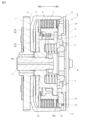
- FIG. 2 is a cross-sectional view taken along line II-II of FIG.
- FIG. 3 is a cross-sectional view taken along line III-III in FIG.
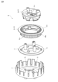
- FIG. 4 is an exploded perspective view of the power transmission device according to the first embodiment.
- FIG. 5 is an exploded perspective view of the power transmission device according to the first embodiment.
- FIG. 6 is an exploded perspective view of the centrifugal clutch means according to the first embodiment.
- FIG. 7 is a perspective view showing the weight member according to the first embodiment.
- FIG. 8 is a plan view and a rear view showing the weight member according to the first embodiment.
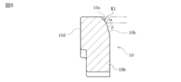
- FIG. 9 is a cross-sectional view taken along line IX-IX in FIG. FIG.
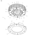
- FIG. 10 is a perspective view showing the pressing member according to the first embodiment.
- FIG. 11 is a plan view and a side view showing the pressing member according to the first embodiment.
- FIG. 12 is a cross-sectional view taken along line XII-XII in FIG.
- FIG. 13 is a perspective view showing the holding member according to the first embodiment.
- FIG. 14 is a sectional view showing the operation of the centrifugal clutch means according to the first embodiment (when the weight member is in the inner diameter position).
- FIG. 15 is a cross-sectional view showing the operation of the centrifugal clutch means according to the first embodiment (when the weight member is in a position between the inner diameter side position and the outer diameter side position).
- FIG. 16 is a sectional view showing the operation of the centrifugal clutch means according to the first embodiment (when the weight member is in the outer diameter side position).
- FIG. 17 is a schematic diagram showing a vehicle to which the power transmission device according to the first embodiment is applied.
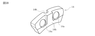
- FIG. 18 is a perspective view showing a weight member according to the second embodiment.
- FIG. 19 is a plan view and a rear view showing a weight member according to the second embodiment.
- FIG. 20 is a cross-sectional view taken along line XX-XX in FIG.
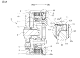
- FIG. 21 is a sectional view showing the operation of the centrifugal clutch means according to the second embodiment (when the weight member is in the inner diameter position).
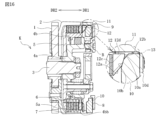
- FIG. 22 is a sectional view showing the operation of the centrifugal clutch means according to the second embodiment (when the weight member is in a position between the inner diameter side position and the outer diameter side position).
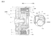
- FIG. 23 is a sectional view showing the operation of the centrifugal clutch means according to the second embodiment (when the weight member is in the outer diameter side position).
- FIG. 24 is a perspective view showing a weight member according to the third embodiment.
- FIG. 25 is a plan view and a rear view showing a weight member according to the third embodiment.
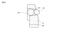
- FIG. 26 is a cross-sectional view taken along line XXVI-XXVI in FIG.
- FIG. 27 is a sectional view showing the operation of the centrifugal clutch means according to the third embodiment (when the weight member is in the inner diameter position).
- FIG. 28 is a sectional view showing the operation of the centrifugal clutch means according to the third embodiment (when the weight member is in a position between the inner diameter side position and the outer diameter side position).
- FIG. 29 is a sectional view showing the operation of the centrifugal clutch means according to the third embodiment (when the weight member is in the outer diameter side position).
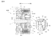
- FIG. 30 is a sectional view showing the operation of the centrifugal clutch means according to the fourth embodiment (when the weight member is in the inner diameter position).
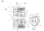
- FIG. 31 is a sectional view showing the operation of the centrifugal clutch means according to the fourth embodiment (when the weight member is in a position between the inner diameter side position and the outer diameter side position).
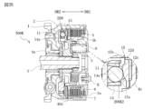
- FIG. 32 is a sectional view showing the operation of the centrifugal clutch means according to the fourth embodiment (when the weight member is in the outer diameter side position).
- FIG. 33 is a sectional view showing the operation of the centrifugal clutch means according to the fifth embodiment (with the weight member in the inner diameter position).
- FIG. 34 is a sectional view showing the operation of the centrifugal clutch means according to the fifth embodiment (when the weight member is in a position between the inner diameter side position and the outer diameter side position).
- FIG. 35 is a sectional view showing the operation of the centrifugal clutch means according to the fifth embodiment (when the weight member is in the outer diameter side position).
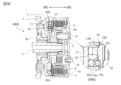
- FIG. 36 is a sectional view showing the operation of the centrifugal clutch means according to the sixth embodiment (when the weight member is in the inner diameter position).
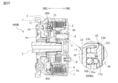
- FIG. 37 is a sectional view showing the operation of the centrifugal clutch means according to the sixth embodiment (when the weight member is in a position between the inner diameter side position and the radial side position).
- FIG. 38 is a sectional view showing the operation of the centrifugal clutch means according to the sixth embodiment (when the weight member is in the outer diameter side position).
- FIG. 39 is a graph showing the relationship between the engine speed and the amount of movement of the pressing member.
- FIG. 40 is a graph showing the relationship between the engine speed and the thrust force exerted by the weight member.
- a power transmission device K is disposed in a vehicle and is used to transmit or cut off the driving force of an engine E to a driving wheel T side via a transmission M.
- the engine E is an example of a driving source.
- the driving wheel T is an example of a wheel.
- FIGS. 1-10 show that FIGS.
- the power transmission device K has a clutch housing 2 in which an input gear 1 that rotates by the driving force of the engine E of the vehicle is formed, an output shaft 3 connected to the transmission M, a clutch member 4, a pressure member 5, a plurality of driving side clutch plates 6 and a plurality of driven side clutch plates 7, and a centrifugal clutch means 9 having a weight member 10.
- the symbol 8 indicates a fixed member
- the symbol S indicates a clutch spring
- the symbol f indicates a return spring
- the symbol B indicates a bolt.
- the input gear 1 is an example of an input member.
- the output shaft 3 is an example of an output member.
- the input gear 1 is configured to be rotatable around the output shaft 3 when the driving force (rotational force) transmitted from the engine E is input.
- the input gear 1 is connected to the clutch housing 2 by rivets or the like.
- the clutch housing 2 is formed in a cylindrical shape with one end open. The clutch housing 2 rotates together with the input gear 1 due to the driving force of the engine E.
- the clutch housing 2 has multiple notches 2a formed around the circumference. Multiple drive side clutch plates 6 are fitted into the notches 2a and attached. That is, the clutch housing 2 holds multiple drive side clutch plates 6.
- the drive side clutch plates 6 are made of a plate material having a roughly annular shape.
- the drive side clutch plates 6 are configured to be movable along the axial direction of the clutch housing 2 (i.e., the axial direction of the output shaft 3) and to be rotatable integrally with the clutch housing 2.
- the clutch member 4 is housed in the clutch housing 2.
- the clutch member 4 holds a plurality of driven clutch plates 7 arranged alternately with the driving clutch plates 6.
- the clutch member 4 is connected to an output shaft 3 capable of rotating the driving wheels T via the transmission M of the vehicle.
- the clutch member 4 includes a first clutch member 4a and a second clutch member 4b. The first clutch member 4a is engaged with the second clutch member 4b.
- the first clutch member 4a has an insertion hole 4ac formed in the center.
- the output shaft 3 is inserted into the insertion hole 4ac, and the splines formed in each hole mesh with each other to connect in the rotational direction. That is, the first clutch member 4a is connected to the output shaft 3.
- the second clutch member 4b has an outer peripheral wall 4bc formed in an annular shape and a flange portion 4bb extending radially outward from the outer peripheral wall 4bc.
- a spline fitting portion 4ba is formed on the outer peripheral wall 4bc.
- the spline fitting portion 4ba has an uneven shape formed integrally around almost the entire circumference of the outer peripheral wall 4bc.
- the driven side clutch plate 7 is attached by spline fitting into the concave groove of the spline fitting portion 4ba. That is, the second clutch member 4b holds the driven side clutch plate 7.
- the driven clutch plate 7 is configured to be movable along the axial direction of the clutch member 4 (e.g., the second clutch member 4b) (i.e., the axial direction of the output shaft 3) and to be rotatable integrally with the clutch member 4 (e.g., the first clutch member 4a and the second clutch member 4b).
- the second clutch member 4b is configured to be movable in the axial direction of the output shaft 3.
- the pressure member 5 is composed of a disk-shaped member with a flange portion 5a formed on its peripheral edge.
- the pressure member 5 is attached to the clutch member 4.
- the pressure member 5 is arranged so that it can move toward or away from the clutch member 4.
- the pressure member 5 is configured so that it can press the driving side clutch plate 6 and the driven side clutch plate 7 together.
- the pressure member 5 is configured so that it can press the driving side clutch plate 6 and the driven side clutch plate 7 together with the clutch member 4.
- the pressure member 5 presses the driving side clutch plate 6 and the driven side clutch plate 7 together, so that the driving force of the engine E can be transmitted to the drive wheels W.
- the driving side clutch plate 6 and the driven side clutch plate 7 are arranged in a stacked state between the flange portion 5a of the pressure member 5 and the flange portion 4bb of the second clutch member 4b, and when the second clutch member 4b moves in a direction approaching the pressure member 5 (the direction of the arrow DR2 in FIG. 2), the driving side clutch plate 6 and the driven side clutch plate 7 are pressed together, and the rotational force of the clutch housing 2 is transmitted to the output shaft 3 via the second clutch member 4b and the first clutch member 4a.
- the second clutch member 4b moves in a direction away from the pressure member 5 (the direction of the arrow DR1 in FIG.
- the driving side clutch plate 6 and the driven side clutch plate 7 are provided so as to be movable in the axial direction of the output shaft 3 relative to the second clutch member 4b.
- the centrifugal clutch means 9 has a weight member 10 that can be moved from an inner diameter side position (see FIG. 14) to an outer diameter side position (see FIG. 16) by centrifugal force accompanying the rotation of the clutch housing 2.
- the centrifugal clutch means 9 is disposed on the opening side (right side in FIG. 2) of the clutch housing 2.
- the centrifugal clutch means 9 is disposed on the opposite side of the pressure member 5 across the driving side clutch plate 6 and the driven side clutch plate 7.
- the centrifugal clutch means 9 is disposed on the arrow DR1 direction side of the pressure member 5 in FIG. 2.
- the centrifugal clutch means 9 presses the driving side clutch plate 6 and the driven side clutch plate 7 together to make it possible to transmit the driving force of the engine E to the driving wheels T.
- the centrifugal clutch means 9 is configured to apply a pressing force to the driving side clutch plate 6 and the driven side clutch plate 7 during the process in which the weight member 10 moves from the inner diameter side position to the outer diameter side position.
- the centrifugal clutch means 9 is configured to release the pressure contact force between the driving side clutch plate 6 and the driven side clutch plate 7 when the weight member 10 is in the inner diameter side position, thereby cutting off the transmission of the driving force of the engine E to the driving wheels T.
- the centrifugal clutch means 9 is configured to release the pressure contact force applied to the driving side clutch plate 6 and the driven side clutch plate 7 when the weight member 10 is in the inner diameter side position, thereby cutting off the transmission of the driving force of the engine E to the driving wheels T.
- the centrifugal clutch means 9 has a plurality of weight members 10, a holding member 11 that holds the weight members 10 movably between an inner diameter side position and an outer diameter side position, a pressure contact member 12, and a plurality of biasing springs 13.
- the weight member 10 has a main body portion 10h, a weight member side cam surface K1 formed on the main body portion 10h, a groove portion 10c formed on the main body portion 10h and holding the biasing spring 13 (see FIG. 6), and a sliding surface 10d formed on the main body portion 10h and capable of sliding against the sliding surface 11b (see FIG. 13) of the holding member 11.
- the weight member 10 is housed in the holding member 11. When no centrifugal force is applied, the weight member 10 is held at the inner diameter side position (see FIG. 14). When centrifugal force is applied, the weight member 10 moves radially outward against the biasing force of the biasing spring 13 and reaches the outer diameter side position (see FIG. 16).
- the weight member 10 moves the clutch member 4 (here, the second clutch member 4b) in a direction approaching the pressure member 5 (the direction of the arrow DR2 in FIG. 2).
- the weight member 10 is configured to press the driving side clutch plate 6 and the driven side clutch plate 7 together via the pressing member 12 as the weight member 10 moves from the inner diameter side position to the outer diameter side position.
- the weight member 10 does not need to press the driving side clutch plate 6 and the driven side clutch plate 7 together via the pressing member 12 at the same time as it starts to move from the inner diameter side position to the outer diameter side position; the driving side clutch plate 6 and the driven side clutch plate 7 may be pressed together via the pressing member 12 after the weight member 10 moves a predetermined distance from the inner diameter side position to the outer diameter side position.
- the weight member side cam surface K1 is arranged to be able to come into contact with the pressure member side cam surface K2 described later.
- the weight member side cam surface K1 is the portion that comes into contact with the pressure member 12.
- the weight member 10 has a first gradient surface 10a and a second gradient surface 10b on the weight member side cam surface K1, the second gradient surface 10b having a gradient angle with respect to the axial direction of the output shaft 3 larger than that of the first gradient surface 10a.
- the first gradient surface 10a is located radially outward from the second gradient surface 10b.
- the first gradient surface 10a is a flat surface.
- the second gradient surface 10b is a flat surface.
- the gradient angle ⁇ of the first gradient surface 10a with respect to the axial direction of the output shaft 3 is smaller than the gradient angle ⁇ of the second gradient surface 10b with respect to the axial direction of the output shaft 3.
- the first gradient surface 10a and the second gradient surface 10b are continuous, but may be connected via a curved surface.
- the centrifugal clutch means 9 has a first gradient surface 10a and a second gradient surface 10b at the portion of the weight member 10 where the weight member 10 and the pressing member 12 contact each other (here, the weight member side cam surface K1).
- the amount of movement of the pressing member 12 in the axial direction of the output shaft 3 at the second gradient surface 10b is smaller than the amount of movement of the pressing member 12 in the axial direction of the output shaft 3 at the first gradient surface 10a.
- the thrust of the weight member 10 generated at the second gradient surface 10b is greater than the thrust of the weight member 10 generated at the first gradient surface 10a.
- the first gradient surface 10a is an example of the first region.
- the second gradient surface 10b is an example of the second region.
- the retaining member 11 holds the weight member 10 movably between an inner diameter side position and an outer diameter side position.
- the retaining member 11 has an annular main body portion 11c, a wall portion 11a extending from the outer periphery of the main body portion 11c, and a sliding surface 11b on which the weight member 10 slides.
- the wall portion 11a contacts one end of the biasing spring 13.
- the pressure contact member 12 is arranged so as to be able to come into contact with the weight member 10.
- the pressure contact member 12 is configured to move in a direction (the direction of the arrow DR2 in FIG. 14) in which the driving side clutch plate 6 and the driven side clutch plate 7 are pressed together by the weight member 10 moving from the inner diameter side position (see FIG. 14) to the outer diameter side position (see FIG. 16).
- the pressure contact member 12 is configured so as to be able to press the driving side clutch plate 6 and the driven side clutch plate 7 together. As shown in FIG. 10 to FIG.
- the pressure contact member 12 has an annular main body portion 12d, a plurality of pressure contact member side cam surfaces K2 formed around the circumferential direction of the main body portion 12d, a pressing surface 12c formed on the surface of the main body portion 12d opposite the surface on which the pressure contact member side cam surface K2 is formed, and a plurality of protrusions 12e formed around the circumferential direction of the main body portion 12d.
- the pressure contact member 12 is attached to the clutch housing 2 by fitting the protrusion 12e into the notch 2a (see FIG. 4) of the clutch housing 2.
- the pressure contact member 12 is provided so as to be movable in the axial direction of the clutch housing 2 (i.e., the axial direction of the output shaft 3).
- the pressure contact member 12 engages with the clutch housing 2 in the rotational direction and is provided so as to be rotatable together with the clutch housing 2.
- the pressure-contact member side cam surface K2 is arranged so as to be able to come into contact with the weight member side cam surface K1.
- the pressure-contact member side cam surface K2 is the portion that comes into contact with the weight member 10.
- the pressure-contact member 12 has a first gradient surface 12a and a second gradient surface 12b on the pressure-contact member side cam surface K2, the second gradient surface 12b having a larger gradient angle with respect to the axial direction of the output shaft 3 than the first gradient surface 12a.
- the first gradient surface 12a is located radially inward from the second gradient surface 12b.
- the first gradient surface 12a is a flat surface.
- the second gradient surface 12b is a flat surface.
- the gradient angle ⁇ of the first gradient surface 12a with respect to the axial direction of the output shaft 3 is smaller than the gradient angle ⁇ of the second gradient surface 12b with respect to the axial direction of the output shaft 3.
- the first gradient surface 12a is arranged so as to be able to come into contact with the first gradient surface 10a of the weight member side cam surface K1.
- the second gradient surface 12b is provided so as to be able to come into contact with the second gradient surface 10b of the weight member side cam surface K1.
- the first gradient surface 12a and the second gradient surface 12b are continuous, but may be connected via a curved surface.
- the centrifugal clutch means 9 has the first gradient surface 12a and the second gradient surface 12b at a portion (here, the pressure member side cam surface K2) where the weight member 10 of the pressure member 12 contacts the pressure member 12.
- the amount of movement of the pressure member 12 in the axial direction of the output shaft 3 on the second gradient surface 12b is smaller than the amount of movement of the pressure member 12 in the axial direction of the output shaft 3 on the first gradient surface 12a.
- the thrust of the weight member 10 generated on the second gradient surface 12b is larger than the thrust of the weight member 10 generated on the first gradient surface 12a.
- the first gradient surface 12a is an example of a first region.
- the second inclined surface 12b is an example of the second region.
- the weight member side cam surface K1 and the pressure member side cam surface K2 are configured so that the gradient surface acting as a cam surface transitions from the first gradient surface 10a and the first gradient surface 12a to the second gradient surface 10b and the second gradient surface 12b in the process of the weight member 10 moving from the inner diameter side position (see FIG. 14) to the outer diameter side position (see FIG. 16).
- the first sloped surface 10a and the first sloped surface 12a act as cam surfaces
- the second sloped surface 10b and the second sloped surface 12b act as cam surfaces
- the first gradient surface 10a and the first gradient surface 12a of the weight member side cam surface K1 and the pressure member side cam surface K2 contact each other and slide against each other before the driving side clutch plate 6 and the driven side clutch plate 7 start to be pressed against each other.
- the thrust generated when the weight member 10 moves from the inner diameter side position to the outer diameter side position is transmitted to the pressure member 12 via the first gradient surface 10a and the first gradient surface 12a.
- the pressure member 12 moves in a direction in which the driving side clutch plate 6 and the driven side clutch plate 7 are pressed against each other (the direction of the arrow DR2 in FIG. 14).
- the thrust of the weight member 10 transmitted to the pressure member 12 becomes relatively small, but the amount of axial movement of the pressure member 12 in the output shaft 3 becomes relatively large.
- the weight member 10 and the pressure contact member 12 may be configured to come into contact with each other at the first slope surface 10a and the first slope surface 12a (i.e., come into contact with each other in the first region) and then come into contact with each other at the second slope surface 10b and the second slope surface 12b (i.e., come into contact with each other in the second region) when the rotation speed of the engine E increases.
- the weight member 10 and the pressure contact member 12 may be configured to come into contact with each other at the first slope surface 10a and the first slope surface 12a (i.e., come into contact with each other in the first region) and then come into contact with each other at the second slope surface 10b and the second slope surface 12b (i.e., come into contact with each other in the second region) when the rotation speed of the engine E is lower than the rotation speed at which the driving side clutch plate 6 and the driven side clutch plate 7 start to be pressed against each other.
- the weight member 10 and the pressing member 12 may be configured to contact each other at the first slope surface 10a and the first slope surface 12a (i.e., contact each other in the first region) and then contact each other at the second slope surface 10b and the second slope surface 12b (i.e., contact each other in the second region). Note that in a region where the rotation speed of the engine E is higher than the rotation speed of the engine E when the pressing of the driving side clutch plate 6 and the driven side clutch plate 7 is completed, the pressing of the driving side clutch plate 6 and the driven side clutch plate 7 is maintained.
- Figure 39 is a graph showing the relationship between the rotation speed of engine E and the axial movement of output shaft 3 of pressure contact member 12.
- the horizontal axis shows the rotation speed of engine E
- the vertical axis shows the axial movement of output shaft 3 of pressure contact member 12.
- Figure 40 is a graph showing the relationship between the rotation speed of engine E and thrust by weight member 10.
- the horizontal axis shows the rotation speed of engine E
- the vertical axis shows thrust by weight member 10.
- the rotation speed EID indicates the rotation speed of the engine E in an idling state
- the rotation speed EC indicates the rotation speed of the engine E when the driving side clutch plates 6 and the driven side clutch plates 7 start to be pressed together (here, when the gradient surfaces acting as cam surfaces transition from the first gradient surfaces 10a and 12a to the second gradient surfaces 10b and 12b)
- the rotation speed EIN indicates the rotation speed of the engine E when the driving force of the engine E begins to be transmitted to the driving wheels T
- the rotation speed EST indicates the rotation speed of the engine E when the driving side clutch plates 6 and the driven side clutch plates 7 are completely pressed together (when the pressing of the driving side clutch plates 6 and the driven side clutch plates 7 is completed)
- the rotation speed EE indicates the rotation speed of the engine E when the weight member 10 reaches the outer diameter side position.
- the centrifugal clutch means 9 has, on the weight member side cam surface K1, first inclined surfaces 10a, 12a and second inclined surfaces 10b, 12b whose inclination angles relative to the axial direction of the output shaft 3 are greater than those of the first inclined surfaces 10a, 12a. According to the above aspect, the required amount of axial movement of the pressure contact member 12 in the output shaft 3 and the thrust force of the weight member 10 can be secured depending on the operating state.
- the weight member 10 and the pressure contact member 12 may come into contact with each other at the first inclined surfaces 10a and 12a, and then come into contact with each other at the second inclined surfaces 10b and 12b. According to the above embodiment, the amount of axial movement of the pressure contact member 12 is first increased, and then the thrust force by the weight member 10 can be increased.
- the first gradient surface 10a and the second gradient surface 10b may be connected via a curved surface, and the first gradient surface 12a and the second gradient surface 12b may be connected via a curved surface.
- the first gradient surface 10a and the second gradient surface 10b are connected via a curved surface, and the first gradient surface 12a and the second gradient surface 12b are connected via a curved surface, so that the contact portion between the weight member 10 and the pressure contact member 12 can be smoothly shifted from the first gradient surfaces 10a, 12a to the second gradient surfaces 10b, 12b.
- the weight member 10 and the pressing member 12 may come into contact with each other at the first sloped surfaces 10a, 12a, and then come into contact with each other at the second sloped surfaces 10b, 12b.
- the contact portion between the weight member 10 and the pressing member 12 is shifted from the first sloped surfaces 10a, 12a to the second sloped surfaces 10b, 12b.
- the necessary amount of movement of the pressing member 12 in the axial direction of the output shaft 3 can be secured before the driving side clutch plate 6 and the driven side clutch plate 7 start to be pressed together, and the necessary thrust by the weight member 10 can be secured after the driving side clutch plate 6 and the driven side clutch plate 7 start to be pressed together.
- the weight member 10 and the pressing member 12 may come into contact with each other at the first sloped surfaces 10a, 12a, and then come into contact with each other at the second sloped surfaces 10b, 12b.
- the contact portion between the weight member 10 and the pressing member 12 is shifted from the first sloped surfaces 10a, 12a to the second sloped surfaces 10b, 12b.
- the necessary amount of movement of the pressing member 12 in the axial direction of the output shaft 3 can be secured until the pressing between the driving side clutch plate 6 and the driven side clutch plate 7 is completed, and the necessary thrust by the weight member 10 can be secured after the pressing between the driving side clutch plate 6 and the driven side clutch plate 7 is completed.
- the weight member 10 has a sliding surface 10d that can slide against the holding member 11, the weight member 10 has a first sloped surface 10a and a second sloped surface 10b at a portion where the weight member 10 and the pressure contact member 12 contact each other (e.g., the weight member side cam surface K1), and the pressure contact member 12 may have a first sloped surface 12a and a second sloped surface 12b at a portion where the weight member 10 and the pressure contact member 12 contact each other (e.g., the pressure contact member side cam surface K2).
- the weight member 10 having the sliding surface 10d that can slide against the holding member 11 can be used well.
- the centrifugal clutch means 9 has first inclined surfaces 10a, 12a as a first region, and second inclined surfaces 10b, 12b as a second region in which the amount of axial movement of the pressure contact member 12 in the output shaft 3 is smaller than in the first region. According to the above aspect, it is possible to ensure the necessary amount of axial movement of the pressure contact member 12 in the output shaft 3 and the thrust by the weight member 10 depending on the operating state. Note that the thrust by the weight member 10 is greater in the second region than in the first region.
- the weight member 10 and the pressure contact member 12 may come into contact with each other at the first inclined surfaces 10a, 12a as the first region, and then come into contact with each other at the second inclined surfaces 10b, 12b as the second region. According to the above embodiment, the amount of axial movement of the pressure contact member 12 is first increased, and then the thrust force by the weight member 10 can be increased.
- the first region is the first sloped surface 10a, 12a consisting of a flat surface
- the second region is the second sloped surface 10b, 12b consisting of a flat surface
- the weight member 10 and the pressure contact member 12 may be configured to be able to contact each other at the first sloped surface 10a, 12a and the second sloped surface 10b, 12b.
- the amount of movement of the pressure contact member 12 and the thrust force by the weight member 10 can be smoothly changed in the first region and the second region.
- a power transmission device 200K according to the second embodiment has a centrifugal clutch means 209 having a weight member 14. Note that the same components as those in the first embodiment are given the same reference numerals, and detailed description thereof will be omitted.
- the centrifugal clutch means 209 has a plurality of weight members 14, a holding member 11 that holds the weight members 14 movably between an inner diameter side position and an outer diameter side position, a pressure contact member 15, and a plurality of biasing springs 13.
- the weight member 14 is configured to be movable from an inner diameter side position (see Figure 21) to an outer diameter side position (see Figure 23) by centrifugal force accompanying rotation of the clutch housing 2.
- the weight member 14 has a main body portion 14h, a spherical member 14a that is in point contact with the retaining member 11 or that can move while rolling, a retaining hole 14f formed in the main body portion 14h and that retains the spherical member 14a, and a groove portion 14b formed in the main body portion 14h and that retains the biasing spring 13.
- the spherical member 14a is an example of a contact portion.
- the pressure contact member 15 is arranged so as to be able to come into contact with the weight member 14.
- the pressure contact member 15 is configured to move in a direction (indicated by arrow DR2 in FIG. 21) in which the driving side clutch plate 6 and the driven side clutch plate 7 are pressed together by the weight member 14 moving from the inner diameter side position (see FIG. 21) to the outer diameter side position (see FIG. 23).
- the pressure contact member 15 is configured so as to be able to press the driving side clutch plate 6 and the driven side clutch plate 7 together.
- the pressure contact member 15 has a pressure contact member side cam surface 200K2 formed around the circumferential direction of the main body portion 12d.
- the pressure-contacting member side cam surface 200K2 is arranged so as to be able to come into contact with the spherical member 14a.
- the pressure-contacting member side cam surface 200K2 is the portion that comes into contact with the weight member 14.
- the pressure-contacting member 15 has a first gradient surface 15a and a second gradient surface 15b on the pressure-contacting member side cam surface 200K2, the second gradient surface 15b having a gradient angle with respect to the axial direction of the output shaft 3 larger than that of the first gradient surface 15a.
- the first gradient surface 15a is located radially inward of the second gradient surface 15b.
- the first gradient surface 15a is a flat surface.
- the second gradient surface 15b is a curved surface.
- the thrust of the weight member 14 generated on the second inclined surface 15b is greater than the thrust of the weight member 14 generated on the first inclined surface 15a.
- the first inclined surface 15a is an example of the first region.
- the second inclined surface 12b is an example of the second region.
- the spherical member 14a and the pressure member side cam surface 200K2 are configured so that the gradient surface acting as a cam surface for the spherical member 14a transitions from the first gradient surface 15a to the second gradient surface 15b in the process of the weight member 14 moving from the inner diameter side position (see FIG. 21) to the outer diameter side position (see FIG. 23).
- the first inclined surface 15a acts as a cam surface before the driving side clutch plate 6 and the driven side clutch plate 7 start to be pressed together
- the second inclined surface 15b acts as a cam surface.
- the spherical member 14a and the first slope surface 15a contact and slide against each other at the spherical member 14a and the pressing member side cam surface K2.
- the thrust generated when the weight member 14 moves from the inner diameter side position to the outer diameter side position is transmitted to the pressing member 15 via the spherical member 14a and the first slope surface 15a.
- the pressing member 15 moves in a direction that presses the driving side clutch plate 6 and the driven side clutch plate 7 against each other (the direction of the arrow DR2 in FIG. 21).
- the thrust of the weight member 14 transmitted to the pressing member 15 becomes relatively small, but the amount of axial movement of the pressing member 15 in the output shaft 3 becomes relatively large.
- a power transmission device 300K according to the third embodiment has a centrifugal clutch means 309 having a weight member 16. Note that the same components as those in the first and second embodiments are given the same reference numerals, and detailed description thereof will be omitted.
- the weight member 16 is configured to be movable from an inner diameter side position (see Figure 27) to an outer diameter side position (see Figure 29) by centrifugal force accompanying the rotation of the clutch housing 2.
- the weight member 16 has a main body portion 16h, a pair of rolling members 16a, 16b that are in point contact with the holding member 11 or can move while rolling, a holding hole 16f formed in the main body portion 16h and holding the rolling members 16a, 16b, and a groove portion 16c formed in the main body portion 16h and holding the biasing spring 13.
- the rolling member 16a is provided so as to be able to come into contact with the pressure contact member side cam surface 200K2.
- the rolling member 16b is provided so as to be able to come into contact with the holding member 11.
- the rolling members 16a, 16b are held in the holding hole 16f so as to be in contact with each other.
- the rolling members 16a, 16b are an example of a contact portion.
- the rolling member 16a and the pressure member side cam surface 200K2 are configured so that the gradient surface acting as a cam surface for the rolling member 16a transitions from the first gradient surface 15a to the second gradient surface 15b in the process of the weight member 16 moving from the inner diameter side position (see FIG. 27) to the outer diameter side position (see FIG. 29).
- the first inclined surface 15a acts as a cam surface before the driving side clutch plate 6 and the driven side clutch plate 7 start to be pressed together
- the second inclined surface 15b acts as a cam surface. Note that the action and effect of the third embodiment are the same as the action and effect of the second embodiment.
- the centrifugal clutch means 9 is disposed on the opening side of the clutch housing 2 (the right side in FIG. 2), but is not limited thereto.
- the centrifugal clutch means 9 may be disposed on the bottom side of the clutch housing 2 (the left side in FIG. 30).
- the centrifugal clutch means 9 is disposed on the opposite side of the pressure member 5 across the driving side clutch plate 6 and the driven side clutch plate 7.
- the centrifugal clutch means 9 is disposed on the side of the clutch member 4 (more specifically, the second clutch member 4b) in the direction of the arrow DR2 in FIG. 30.
- the centrifugal clutch means 209 is disposed on the opening side of the clutch housing 2 (the right side in FIG. 21), but is not limited thereto.
- the centrifugal clutch means 209 may be disposed on the bottom side of the clutch housing 2 (the left side in FIG. 33).
- the centrifugal clutch means 209 is disposed on the opposite side of the pressure member 5 across the driving side clutch plate 6 and the driven side clutch plate 7.
- the centrifugal clutch means 209 is disposed on the arrow DR2 direction side in FIG. 33 relative to the clutch member 4 (more specifically, the second clutch member 4b).
- the centrifugal clutch means 309 is disposed on the opening side of the clutch housing 2 (the right side in FIG. 27), but is not limited thereto.
- the centrifugal clutch means 309 may be disposed on the bottom side of the clutch housing 2 (the left side in FIG. 36).
- the centrifugal clutch means 309 is disposed on the opposite side of the pressure member 5 across the driving side clutch plate 6 and the driven side clutch plate 7.
- the centrifugal clutch means 309 is disposed on the side of the clutch member 4 (more specifically, the second clutch member 4b) in the direction of the arrow DR2 in FIG. 36.
- the centrifugal clutch means 9 has a first gradient surface 10a and a second gradient surface 10b on the weight member side cam surface K1, and a first gradient surface 12a and a second gradient surface 12b on the pressure member side cam surface K2, but is not limited to this.
- the centrifugal clutch means 9 may have a first gradient surface 10a and a second gradient surface 10b on the weight member side cam surface K1, and may not have a first gradient surface 12a and a second gradient surface 12b on the pressure member side cam surface K2.
- centrifugal clutch means 9 may not have a first gradient surface 10a and a second gradient surface 10b on the weight member side cam surface K1, and may have a first gradient surface 12a and a second gradient surface 12b on the pressure member side cam surface K2.
- the first gradient surface 10a, the second gradient surface 10b, the first gradient surface 12a, and the second gradient surface 12b are each flat, but they may also be curved. Furthermore, if at least one of the first gradient surface 10a and the second gradient surface 10b is a curved surface, it is preferable that it has a convex shape facing outward (for example, toward the direction of the arrow DR2 in FIG. 14). If at least one of the first gradient surface 12a and the second gradient surface 12b is a curved surface, it is preferable that it has a convex shape facing outward (for example, toward the direction of the arrow DR1 in FIG. 14).
- the weight member 10 has a first gradient surface 10a and a second gradient surface 10b on the weight member side cam surface K1, the gradient angle of which is greater than that of the first gradient surface 10a relative to the axial direction of the output shaft 3, but is not limited to this.
- the weight member 10 may also have a third gradient surface radially outward of the first gradient surface 10a, the gradient angle of which is smaller than that of the first gradient surface 10a relative to the axial direction of the output shaft 3.
- the weight member 10 may also have a fourth gradient surface radially inward of the second gradient surface 10b, the gradient angle of which is greater than that of the second gradient surface 10b relative to the axial direction of the output shaft 3.
- the pressure contact member 12 has a first gradient surface 12a and a second gradient surface 12b on the pressure contact member side cam surface K2, the gradient angle of which is greater with respect to the axial direction of the output shaft 3 than the first gradient surface 12a, but is not limited to this.
- the pressure contact member 12 may also have a third gradient surface radially inward from the first gradient surface 12a, the gradient angle of which is smaller with respect to the axial direction of the output shaft 3 than the first gradient surface 12a.
- the pressure contact member 12 may also have a fourth gradient surface radially outward from the second gradient surface 12b, the gradient angle of which is greater with respect to the axial direction of the output shaft 3 than the second gradient surface 12b.
- the pressure contact member 15 has a first gradient surface 15a and a second gradient surface 15b on the pressure contact member side cam surface 200K2, the gradient angle of which is greater with respect to the axial direction of the output shaft 3 than the first gradient surface 15a, but this is not limited to the above.
- the pressure contact member 15 may also have a third gradient surface radially inward from the first gradient surface 15a, the gradient angle of which is smaller with respect to the axial direction of the output shaft 3 than the first gradient surface 15a.
- the pressure contact member 15 may also have a fourth gradient surface radially outward from the second gradient surface 15b, the gradient angle of which is greater with respect to the axial direction of the output shaft 3 than the second gradient surface 15b.
- all of the driven clutch plates 7 are held by the clutch member 4 (e.g., the second clutch member 4b), but this is not limited to the above.
- a portion of the driven clutch plates 7 may be held by the clutch member 4 (e.g., the second clutch member 4b), and another portion of the driven clutch plates 7 may be held by the pressure member 5.
- the other portion of the driven clutch plates 7 is configured to be movable along the axial direction of the pressure member 5 (i.e., the axial direction of the output shaft 3) and to be rotatable integrally with the pressure member 5.
- the engine E is used as the driving source, but the driving source is not limited to the engine E and may be, for example, an electric motor, etc.
- the power transmission devices of the above-mentioned embodiments can be applied to various multi-plate clutch type power transmission devices, such as motorcycles, automobiles, three- or four-wheeled buggies, or general-purpose machines.
Landscapes
- Engineering & Computer Science (AREA)
- General Engineering & Computer Science (AREA)
- Mechanical Engineering (AREA)
- One-Way And Automatic Clutches, And Combinations Of Different Clutches (AREA)
- Mechanical Operated Clutches (AREA)
Abstract
Description
以下、本発明の実施形態について図面を参照しながら具体的に説明する。図17に示すように、動力伝達装置Kは、車両に配設されて任意にエンジンEの駆動力をミッションMを介して駆動輪T側へ伝達し又は遮断するためのものである。エンジンEは、駆動源の一例である。駆動輪Tは、車輪の一例である。図1~16に示すように、動力伝達装置Kは、車両のエンジンEの駆動力で回転する入力ギア1が形成されたクラッチハウジング2と、ミッションMに接続された出力シャフト3と、クラッチ部材4と、プレッシャ部材5と、複数の駆動側クラッチ板6及び複数の被動側クラッチ板7と、ウェイト部材10を有する遠心クラッチ手段9と、を有している。なお、図中符号8は固定部材、符号Sはクラッチスプリング、符号fはリターンスプリング、符号Bはボルトをそれぞれ示している。入力ギア1は、入力部材の一例である。出力シャフト3は、出力部材の一例である。
図21~23に示すように、第2実施形態に係る動力伝達装置200Kは、ウェイト部材14を有する遠心クラッチ手段209を有している。なお、第1実施形態と同様の構成要素には、同一の符号を付すこととし、詳細な説明を省略する。
図27~29に示すように、第3実施形態に係る動力伝達装置300Kは、ウェイト部材16を有する遠心クラッチ手段309を有している。なお、第1実施形態および第2実施形態と同様の構成要素には、同一の符号を付すこととし、詳細な説明を省略する。
上述した第1実施形態では、遠心クラッチ手段9は、クラッチハウジング2の開口側(図2中右側)に配置されていたが、これに限定されない。例えば、第4実施形態に係る動力伝達装置400Kでは、図30~図32に示すように、遠心クラッチ手段9は、クラッチハウジング2の底面側(図30中左側)に配置されていてもよい。遠心クラッチ手段9は、駆動側クラッチ板6および被動側クラッチ板7を挟んでプレッシャ部材5の反対側に配置されている。ここでは、遠心クラッチ手段9は、クラッチ部材4(より詳細には第2クラッチ部材4b)よりも図30の矢印DR2方向側に配置されている。
上述した第2実施形態では、遠心クラッチ手段209は、クラッチハウジング2の開口側(図21中右側)に配置されていたが、これに限定されない。例えば、第5実施形態に係る動力伝達装置500Kでは、図33~図35に示すように、遠心クラッチ手段209は、クラッチハウジング2の底面側(図33中左側)に配置されていてもよい。遠心クラッチ手段209は、駆動側クラッチ板6および被動側クラッチ板7を挟んでプレッシャ部材5の反対側に配置されている。ここでは、遠心クラッチ手段209は、クラッチ部材4(より詳細には第2クラッチ部材4b)よりも図33の矢印DR2方向側に配置されている。
上述した第3実施形態では、遠心クラッチ手段309は、クラッチハウジング2の開口側(図27中右側)に配置されていたが、これに限定されない。例えば、第6実施形態に係る動力伝達装置600Kでは、図36~図38に示すように、遠心クラッチ手段309は、クラッチハウジング2の底面側(図36中左側)に配置されていてもよい。遠心クラッチ手段309は、駆動側クラッチ板6および被動側クラッチ板7を挟んでプレッシャ部材5の反対側に配置されている。ここでは、遠心クラッチ手段309は、クラッチ部材4(より詳細には第2クラッチ部材4b)よりも図36の矢印DR2方向側に配置されている。
2 クラッチハウジング
3 出力シャフト(出力部材)
4 クラッチ部材
4a 第1クラッチ部材
4b 第2クラッチ部材
5 プレッシャ部材
6 駆動側クラッチ板
7 被動側クラッチ板
9 遠心クラッチ手段
10 ウェイト部材
10a 第1勾配面
10b 第2勾配面
11 保持部材
12 圧接部材
12a 第1勾配面
12b 第2勾配面
14 ウェイト部材
14a 球状部材(接触部)
15 圧接部材
15a 第1勾配面
15b 第2勾配面
16 ウェイト部材
16a、16b 転動部材(接触部)
K 動力伝達装置
K1 ウェイト部材側カム面
K2 圧接部材側カム面
Claims (13)
- 駆動源の駆動力で回転する入力部材と共に回転し、かつ、複数の駆動側クラッチ板を保持するクラッチハウジングに収容され、かつ、車輪を回転させ得る出力部材と連結されたクラッチ部材と、
前記クラッチ部材に対して接近または離隔可能に設けられ、かつ、前記駆動側クラッチ板と交互に配置された複数の被動側クラッチ板および複数の前記駆動側クラッチ板を押圧可能なプレッシャ部材と、
前記クラッチハウジングの回転に伴う遠心力により内径側位置から外径側位置に移動可能とされたウェイト部材と、前記ウェイト部材と接触可能に設けられかつ前記ウェイト部材が前記内径側位置から前記外径側位置に移動することにより前記駆動側クラッチ板および前記被動側クラッチ板を圧接させる方向に移動する圧接部材と、を有し、かつ、前記ウェイト部材が前記外径側位置にあるときに前記駆動側クラッチ板と前記被動側クラッチ板とを圧接させて前記駆動源の駆動力を前記車輪に伝達可能な状態とするとともに、前記ウェイト部材が前記内径側位置にあるときに前記駆動側クラッチ板と前記被動側クラッチ板との圧接力を解放させて前記駆動源の駆動力が前記車輪に伝達されるのを遮断し得る遠心クラッチ手段と、を備え、
前記ウェイト部材は、前記ウェイト部材が前記内径側位置から前記外径側位置に移動する過程において前記圧接部材を介して前記駆動側クラッチ板と前記被動側クラッチ板とを圧接させるように構成され、
前記遠心クラッチ手段は、前記ウェイト部材および前記圧接部材の少なくともいずれか一方の前記ウェイト部材と前記圧接部材とが接触する部分に、第1勾配面と、前記第1勾配面よりも前記出力部材の軸方向に対する勾配角度が大きい第2勾配面と、を有する、動力伝達装置。 - 前記駆動源の回転数が上昇する過程で、前記ウェイト部材と前記圧接部材とは前記第1勾配面で相互に接触した後、前記第2勾配面で相互に接触する、請求項1に記載の動力伝達装置。
- 前記第1勾配面と前記第2勾配面とは、曲面を介して接続されている、請求項1または2に記載の動力伝達装置。
- 前記駆動源の回転数が前記駆動側クラッチ板と前記被動側クラッチ板とが圧接を開始するときの回転数よりも低いときに、前記ウェイト部材と前記圧接部材とは前記第1勾配面で相互に接触した後、前記第2勾配面で相互に接触する、請求項1または2に記載の動力伝達装置。
- 前記駆動源の回転数が前記駆動側クラッチ板と前記被動側クラッチ板との圧接が完了するときの回転数よりも低いときに、前記ウェイト部材と前記圧接部材とは前記第1勾配面で相互に接触した後、前記第2勾配面で相互に接触する、請求項1または2に記載の動力伝達装置。
- 前記遠心クラッチ手段は、前記ウェイト部材を前記内径側位置と前記外径側位置との間で移動可能に保持する保持部材を有し、
前記ウェイト部材は、前記保持部材に対して摺動可能な摺動面を有し、
前記ウェイト部材は、前記ウェイト部材と前記圧接部材とが接触する部分に、前記第1勾配面と前記第2勾配面と、を有し、
前記圧接部材は、前記ウェイト部材と前記圧接部材とが接触する部分に、前記第1勾配面と前記第2勾配面と、を有する、請求項1または2に記載の動力伝達装置。 - 前記遠心クラッチ手段は、前記ウェイト部材を前記内径側位置と前記外径側位置との間で移動可能に保持する保持部材を有し、
前記ウェイト部材は、前記保持部材に対して点接触または転動しつつ移動可能な接触部を有し、
前記圧接部材は、前記ウェイト部材と前記圧接部材とが接触する部分に、前記第1勾配面と前記第2勾配面と、を有する、請求項1または2に記載の動力伝達装置。 - 駆動源の駆動力で回転する入力部材と共に回転し、かつ、複数の駆動側クラッチ板を保持するクラッチハウジングに収容され、かつ、車輪を回転させ得る出力部材と連結されたクラッチ部材と、
前記クラッチ部材に対して接近または離隔可能に設けられ、かつ、前記駆動側クラッチ板と交互に配置された複数の被動側クラッチ板および複数の前記駆動側クラッチ板を押圧可能なプレッシャ部材と、
前記クラッチハウジングの回転に伴う遠心力により内径側位置から外径側位置に移動可能とされたウェイト部材と、前記ウェイト部材と接触可能に設けられかつ前記ウェイト部材が前記内径側位置から前記外径側位置に移動することにより前記駆動側クラッチ板および前記被動側クラッチ板を圧接させる方向に移動する圧接部材と、を有し、かつ、前記ウェイト部材が前記外径側位置にあるときに前記駆動側クラッチ板と前記被動側クラッチ板とを圧接させて前記駆動源の駆動力を前記車輪に伝達可能な状態とするとともに、前記ウェイト部材が前記内径側位置にあるときに前記駆動側クラッチ板と前記被動側クラッチ板との圧接力を解放させて前記駆動源の駆動力が前記車輪に伝達されるのを遮断し得る遠心クラッチ手段と、を備え、
前記ウェイト部材は、前記ウェイト部材が前記内径側位置から前記外径側位置に移動する過程において前記圧接部材を介して前記駆動側クラッチ板と前記被動側クラッチ板とを圧接させるように構成され、
前記遠心クラッチ手段は、前記ウェイト部材および前記圧接部材の少なくともいずれか一方の前記ウェイト部材と前記圧接部材とが接触する部分に、第1領域と、前記第1領域よりも前記圧接部材の前記出力部材の軸方向の移動量が小さい第2領域と、を有する、動力伝達装置。 - 前記駆動源の回転数が上昇する過程で、前記ウェイト部材と前記圧接部材とは前記第1領域で相互に接触した後、前記第2領域で相互に接触する、請求項8に記載の動力伝達装置。
- 前記第1領域は、平面からなる第1勾配面であり、
前記第2領域は、平面からなる第2勾配面であり、
前記ウェイト部材と前記圧接部材とは前記第1勾配面および前記第2勾配面で相互に接触可能に構成されている、請求項8または9に記載の動力伝達装置。 - 駆動源の駆動力で回転する入力部材と共に回転し、かつ、複数の駆動側クラッチ板を保持するクラッチハウジングに収容され、かつ、車輪を回転させ得る出力部材と連結されたクラッチ部材と、
前記クラッチ部材に対して接近または離隔可能に設けられ、かつ、前記駆動側クラッチ板と交互に配置された複数の被動側クラッチ板および複数の前記駆動側クラッチ板を押圧可能なプレッシャ部材と、
前記クラッチハウジングの回転に伴う遠心力により内径側位置から外径側位置に移動可能とされたウェイト部材と、前記ウェイト部材と接触可能に設けられかつ前記ウェイト部材が前記内径側位置から前記外径側位置に移動することにより前記駆動側クラッチ板および前記被動側クラッチ板を圧接させる方向に移動する圧接部材と、を有し、かつ、前記ウェイト部材が前記外径側位置にあるときに前記駆動側クラッチ板と前記被動側クラッチ板とを圧接させて前記駆動源の駆動力を前記車輪に伝達可能な状態とするとともに、前記ウェイト部材が前記内径側位置にあるときに前記駆動側クラッチ板と前記被動側クラッチ板との圧接力を解放させて前記駆動源の駆動力が前記車輪に伝達されるのを遮断し得る遠心クラッチ手段と、を備え、
前記ウェイト部材は、前記ウェイト部材が前記内径側位置から前記外径側位置に移動する過程において前記圧接部材を介して前記駆動側クラッチ板と前記被動側クラッチ板とを圧接させるように構成され、
前記遠心クラッチ手段は、前記ウェイト部材および前記圧接部材の少なくともいずれか一方の前記ウェイト部材と前記圧接部材とが接触する部分に、第1領域と、前記第1領域よりも前記ウェイト部材による推力が大きい第2領域と、を有する、動力伝達装置。 - 前記駆動源の回転数が上昇する過程で、前記ウェイト部材と前記圧接部材とは前記第1領域で相互に接触した後、前記第2領域で相互に接触する、請求項11に記載の動力伝達装置。
- 前記第1領域は、平面からなる第1勾配面であり、
前記第2領域は、平面からなる第2勾配面であり、
前記ウェイト部材と前記圧接部材とは前記第1勾配面および前記第2勾配面で相互に接触可能に構成されている、請求項11または12に記載の動力伝達装置。
Priority Applications (4)
| Application Number | Priority Date | Filing Date | Title |
|---|---|---|---|
| JP2024540757A JPWO2024150644A1 (ja) | 2023-01-11 | 2023-12-21 | |
| EP23916258.9A EP4567292A4 (en) | 2023-01-11 | 2023-12-21 | ENERGY TRANSMISSION DEVICE |
| CN202380064868.5A CN119856002A (zh) | 2023-01-11 | 2023-12-21 | 动力传递装置 |
| JP2024193548A JP7833520B2 (ja) | 2023-01-11 | 2024-11-05 | 動力伝達装置 |
Applications Claiming Priority (2)
| Application Number | Priority Date | Filing Date | Title |
|---|---|---|---|
| JP2023002564 | 2023-01-11 | ||
| JP2023-002564 | 2023-01-11 |
Publications (1)
| Publication Number | Publication Date |
|---|---|
| WO2024150644A1 true WO2024150644A1 (ja) | 2024-07-18 |
Family
ID=91896865
Family Applications (1)
| Application Number | Title | Priority Date | Filing Date |
|---|---|---|---|
| PCT/JP2023/046015 Ceased WO2024150644A1 (ja) | 2023-01-11 | 2023-12-21 | 動力伝達装置 |
Country Status (4)
| Country | Link |
|---|---|
| EP (1) | EP4567292A4 (ja) |
| JP (2) | JPWO2024150644A1 (ja) |
| CN (1) | CN119856002A (ja) |
| WO (1) | WO2024150644A1 (ja) |
Cited By (1)
| Publication number | Priority date | Publication date | Assignee | Title |
|---|---|---|---|---|
| JP2025016698A (ja) * | 2023-01-11 | 2025-02-04 | 株式会社エフ・シー・シー | 動力伝達装置 |
Citations (5)
| Publication number | Priority date | Publication date | Assignee | Title |
|---|---|---|---|---|
| JP2002021879A (ja) * | 2000-07-05 | 2002-01-23 | Yamaha Motor Co Ltd | エンジンの遠心式クラッチ装置 |
| JP3155714U (ja) * | 2008-10-10 | 2009-11-26 | ヤマハ発動機株式会社 | 摩擦クラッチおよびそれを備えた車両 |
| JP2012037020A (ja) * | 2010-08-11 | 2012-02-23 | Honda Motor Co Ltd | クラッチ装置 |
| WO2013183588A1 (ja) | 2012-06-04 | 2013-12-12 | 株式会社エフ・シ-・シ- | 動力伝達装置 |
| JP2022030211A (ja) * | 2020-08-06 | 2022-02-18 | 株式会社エフ・シー・シー | 動力伝達装置 |
Family Cites Families (4)
| Publication number | Priority date | Publication date | Assignee | Title |
|---|---|---|---|---|
| JP7161285B2 (ja) * | 2017-11-10 | 2022-10-26 | 株式会社エクセディ | クラッチ装置 |
| JP7480281B2 (ja) * | 2020-04-13 | 2024-05-09 | 株式会社エフ・シー・シー | 動力伝達装置 |
| WO2024085186A1 (ja) * | 2022-10-20 | 2024-04-25 | 株式会社エフ・シー・シー | 動力伝達装置 |
| EP4567292A4 (en) | 2023-01-11 | 2026-01-07 | Fcc Kk | ENERGY TRANSMISSION DEVICE |
-
2023
- 2023-12-21 EP EP23916258.9A patent/EP4567292A4/en active Pending
- 2023-12-21 CN CN202380064868.5A patent/CN119856002A/zh active Pending
- 2023-12-21 JP JP2024540757A patent/JPWO2024150644A1/ja active Pending
- 2023-12-21 WO PCT/JP2023/046015 patent/WO2024150644A1/ja not_active Ceased
-
2024
- 2024-11-05 JP JP2024193548A patent/JP7833520B2/ja active Active
Patent Citations (5)
| Publication number | Priority date | Publication date | Assignee | Title |
|---|---|---|---|---|
| JP2002021879A (ja) * | 2000-07-05 | 2002-01-23 | Yamaha Motor Co Ltd | エンジンの遠心式クラッチ装置 |
| JP3155714U (ja) * | 2008-10-10 | 2009-11-26 | ヤマハ発動機株式会社 | 摩擦クラッチおよびそれを備えた車両 |
| JP2012037020A (ja) * | 2010-08-11 | 2012-02-23 | Honda Motor Co Ltd | クラッチ装置 |
| WO2013183588A1 (ja) | 2012-06-04 | 2013-12-12 | 株式会社エフ・シ-・シ- | 動力伝達装置 |
| JP2022030211A (ja) * | 2020-08-06 | 2022-02-18 | 株式会社エフ・シー・シー | 動力伝達装置 |
Non-Patent Citations (1)
| Title |
|---|
| See also references of EP4567292A4 |
Cited By (2)
| Publication number | Priority date | Publication date | Assignee | Title |
|---|---|---|---|---|
| JP2025016698A (ja) * | 2023-01-11 | 2025-02-04 | 株式会社エフ・シー・シー | 動力伝達装置 |
| JP7833520B2 (ja) | 2023-01-11 | 2026-03-19 | 株式会社エフ・シー・シー | 動力伝達装置 |
Also Published As
| Publication number | Publication date |
|---|---|
| EP4567292A1 (en) | 2025-06-11 |
| JP2025016698A (ja) | 2025-02-04 |
| EP4567292A4 (en) | 2026-01-07 |
| JPWO2024150644A1 (ja) | 2024-07-18 |
| JP7833520B2 (ja) | 2026-03-19 |
| CN119856002A (zh) | 2025-04-18 |
Similar Documents
| Publication | Publication Date | Title |
|---|---|---|
| JP5502507B2 (ja) | 動力伝達装置 | |
| JP6388351B2 (ja) | 動力伝達装置 | |
| CN110454513B (zh) | 动力传递装置 | |
| CN115853922B (zh) | 动力传递装置 | |
| JP6502443B2 (ja) | 動力伝達装置 | |
| CN111051721B (zh) | 动力传递装置 | |
| WO2013137413A1 (ja) | 動力伝達装置 | |
| JP7789977B2 (ja) | 動力伝達装置 | |
| CN115427703A (zh) | 动力传递装置 | |
| JP2009063023A (ja) | 動力伝達装置 | |
| JP5227229B2 (ja) | 動力伝達装置 | |
| JP4223461B2 (ja) | 動力伝達装置 | |
| JP2025016698A (ja) | 動力伝達装置 | |
| WO2024085186A1 (ja) | 動力伝達装置 | |
| JP2025107395A (ja) | 動力伝達装置 | |
| WO2007088766A1 (ja) | 動力伝達装置 | |
| JP4364170B2 (ja) | 動力伝達装置 | |
| JP7463628B1 (ja) | 動力伝達装置 | |
| WO2007032283A1 (ja) | 動力伝達装置 | |
| WO2007034696A1 (ja) | 動力伝達装置 |
Legal Events
| Date | Code | Title | Description |
|---|---|---|---|
| WWE | Wipo information: entry into national phase |
Ref document number: 2024540757 Country of ref document: JP |
|
| 121 | Ep: the epo has been informed by wipo that ep was designated in this application |
Ref document number: 23916258 Country of ref document: EP Kind code of ref document: A1 |
|
| WWE | Wipo information: entry into national phase |
Ref document number: 202537014147 Country of ref document: IN |
|
| WWE | Wipo information: entry into national phase |
Ref document number: 2023916258 Country of ref document: EP |
|
| ENP | Entry into the national phase |
Ref document number: 2023916258 Country of ref document: EP Effective date: 20250303 |
|
| WWE | Wipo information: entry into national phase |
Ref document number: 202380064868.5 Country of ref document: CN |
|
| WWP | Wipo information: published in national office |
Ref document number: 202537014147 Country of ref document: IN |
|
| WWP | Wipo information: published in national office |
Ref document number: 202380064868.5 Country of ref document: CN |
|
| WWP | Wipo information: published in national office |
Ref document number: 2023916258 Country of ref document: EP |
|
| NENP | Non-entry into the national phase |
Ref country code: DE |