WO2024150724A1 - 符号化方法、復号方法、符号化装置及び復号装置 - Google Patents
符号化方法、復号方法、符号化装置及び復号装置 Download PDFInfo
- Publication number
- WO2024150724A1 WO2024150724A1 PCT/JP2024/000110 JP2024000110W WO2024150724A1 WO 2024150724 A1 WO2024150724 A1 WO 2024150724A1 JP 2024000110 W JP2024000110 W JP 2024000110W WO 2024150724 A1 WO2024150724 A1 WO 2024150724A1
- Authority
- WO
- WIPO (PCT)
- Prior art keywords
- samples
- axis
- information
- mesh
- encoding
- Prior art date
- Legal status (The legal status is an assumption and is not a legal conclusion. Google has not performed a legal analysis and makes no representation as to the accuracy of the status listed.)
- Ceased
Links
Images
















Classifications
-
- G—PHYSICS
- G06—COMPUTING OR CALCULATING; COUNTING
- G06T—IMAGE DATA PROCESSING OR GENERATION, IN GENERAL
- G06T9/00—Image coding
-
- G—PHYSICS
- G06—COMPUTING OR CALCULATING; COUNTING
- G06T—IMAGE DATA PROCESSING OR GENERATION, IN GENERAL
- G06T9/00—Image coding
- G06T9/001—Model-based coding, e.g. wire frame
-
- G—PHYSICS
- G06—COMPUTING OR CALCULATING; COUNTING
- G06T—IMAGE DATA PROCESSING OR GENERATION, IN GENERAL
- G06T17/00—Three-dimensional [3D] modelling for computer graphics
- G06T17/20—Finite element generation, e.g. wire-frame surface description, tesselation
-
- H—ELECTRICITY
- H04—ELECTRIC COMMUNICATION TECHNIQUE
- H04N—PICTORIAL COMMUNICATION, e.g. TELEVISION
- H04N19/00—Methods or arrangements for coding, decoding, compressing or decompressing digital video signals
- H04N19/50—Methods or arrangements for coding, decoding, compressing or decompressing digital video signals using predictive coding
- H04N19/597—Methods or arrangements for coding, decoding, compressing or decompressing digital video signals using predictive coding specially adapted for multi-view video sequence encoding
-
- H—ELECTRICITY
- H04—ELECTRIC COMMUNICATION TECHNIQUE
- H04N—PICTORIAL COMMUNICATION, e.g. TELEVISION
- H04N19/00—Methods or arrangements for coding, decoding, compressing or decompressing digital video signals
- H04N19/70—Methods or arrangements for coding, decoding, compressing or decompressing digital video signals characterised by syntax aspects related to video coding, e.g. related to compression standards
Definitions
- This disclosure relates to encoding methods, etc.
- Patent document 1 proposes a method and device for encoding and decoding three-dimensional mesh data.
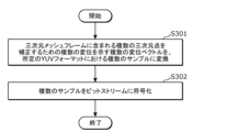
- An encoding method converts a plurality of displacement vectors, indicating a plurality of displacements for correcting a plurality of three-dimensional points included in a three-dimensional mesh frame, into a plurality of samples in a predetermined YUV format, and encodes the plurality of samples into a bitstream, the plurality of samples including two or more Y samples corresponding to Y, one or more U samples corresponding to U, and one or more V samples corresponding to V, the two or more Y samples being more than the one or more U samples and more than the one or more V samples.
- This disclosure may contribute to improvements in encoding processes related to three-dimensional data.
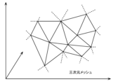
- FIG. 2 is a conceptual diagram showing a three-dimensional mesh according to the embodiment.
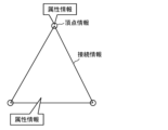
- FIG. 2 is a conceptual diagram showing basic elements of a three-dimensional mesh according to an embodiment.
- FIG. 1 is a conceptual diagram illustrating mapping according to an embodiment. 1 is a block diagram showing an example of a configuration of an encoding/decoding system according to an embodiment; 1 is a block diagram showing an example of the configuration of an encoding device according to an embodiment;
- FIG. 13 is a block diagram showing another example configuration of an encoding device according to an embodiment.
- FIG. 2 is a block diagram showing an example of a configuration of a decoding device according to an embodiment.
- FIG. 13 is a block diagram showing another example configuration of a decoding device according to an embodiment.
- FIG. 1 is a block diagram showing an example of a configuration of an encoding/decoding system according to an embodiment
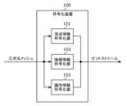
- 1 is a block diagram showing an example of the configuration of an encoding device according to an embodiment
- FIG. 13 is a block
- FIG. 2 is a conceptual diagram showing an example of a configuration of a bit stream according to an embodiment.
- FIG. 11 is a conceptual diagram showing another example of the configuration of a bit stream according to the embodiment.
- FIG. 11 is a conceptual diagram showing yet another example configuration of a bitstream according to an embodiment.
- 1 is a block diagram showing a specific example of an encoding/decoding system according to an embodiment;
- FIG. 2 is a conceptual diagram illustrating an example of a configuration of point cloud data according to the embodiment.
- FIG. 2 is a conceptual diagram illustrating an example of a data file of point cloud data according to the embodiment.
- FIG. 2 is a conceptual diagram showing an example of the configuration of mesh data according to the embodiment;
- FIG. 4 is a conceptual diagram showing an example of a data file of mesh data according to the embodiment.
- FIG. 2 is a conceptual diagram showing types of three-dimensional data according to the embodiment.
- 1 is a block diagram showing an example of the configuration of a three-dimensional data encoder according to an embodiment
- 2 is a block diagram showing an example of the configuration of a three-dimensional data decoder according to an embodiment
- FIG. 13 is a block diagram showing another example configuration of a three-dimensional data encoder according to an embodiment.
- FIG. 13 is a block diagram showing another example configuration of the three-dimensional data decoder according to the embodiment.
- FIG. 11 is a conceptual diagram showing a specific example of an encoding process according to the embodiment.
- FIG. 11 is a conceptual diagram showing a specific example of a decoding process according to an embodiment.
- FIG. 2 is a block diagram showing an implementation example of an encoding device according to an embodiment.
- FIG. 2 is a block diagram showing an implementation example of a decoding device according to an embodiment.
- FIG. 1 is a diagram showing a configuration of an encoding/decoding system according to an embodiment.
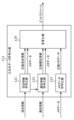
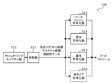
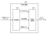
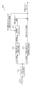
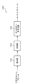
- FIG. 1 illustrates an example of a configuration of an encoding device according to an embodiment.
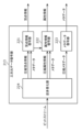
- FIG. 13 is a diagram illustrating another example of the configuration of an encoding device according to an embodiment.
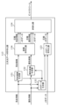
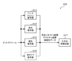
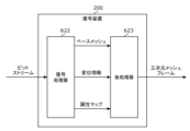
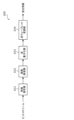
- FIG. 2 is a diagram illustrating an example of a configuration of a decoding device according to an embodiment.
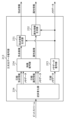
- FIG. 13 is a diagram illustrating another example of the configuration of a decoding device according to an embodiment.
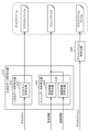
- FIG. 1 is a diagram showing a configuration of an encoding/decoding system according to an embodiment.
- FIG. 1 illustrates an example of a configuration of an encoding device according to an embodiment.
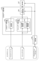
- FIG. 13 is a diagram illustrating another example of the configuration of an encoding device
- FIG. 13 is a diagram illustrating yet another example of the configuration of a decoding device according to an embodiment.
- FIG. 13 is a conceptual diagram illustrating an example of a subdivision according to an embodiment.
- FIG. 13 is a diagram illustrating yet another example of the configuration of a decoding device according to an embodiment.
- FIG. 13 is a diagram for explaining conversion of components of a displacement vector in a local coordinate system when the YUV420 format is used.
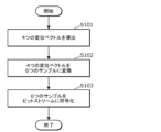
- 1 is a flowchart showing an encoding process according to an embodiment.
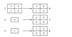
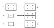
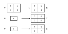
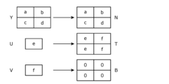
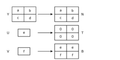
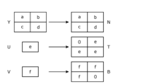
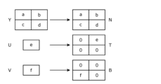
- 11 is a diagram for explaining component values and samples of a displacement vector in the embodiment.
- FIG. 11 is a diagram showing a first example of a correspondence relationship between component values of a displacement vector and samples in the embodiment; FIG. FIG.
- FIG. 11 is a diagram showing a second example of a correspondence relationship between component values of a displacement vector and samples in the embodiment.
- FIG. 13 is a diagram showing a third example of a correspondence relationship between component values of a displacement vector and samples in the embodiment.
- FIG. 13 is a diagram showing a fourth example of a correspondence relationship between component values of a displacement vector and samples in the embodiment.
- FIG. 13 is a diagram showing a fifth example of a correspondence relationship between component values of a displacement vector and samples in the embodiment.
- FIG. 13 is a diagram showing a sixth example of a correspondence relationship between component values of a displacement vector and samples in the embodiment.
- FIG. 13 is a diagram showing a seventh example of a correspondence relationship between component values of a displacement vector and samples in the embodiment.
- FIG. 13 is a diagram showing an example of converting six samples into four displacement vectors in a three-axis coordinate system according to an embodiment.
- FIG. 13 is a block diagram showing yet another example of the configuration of an encoding device according to an embodiment.
- 11 is a flowchart showing a decoding process according to an embodiment.
- FIG. 13 is a block diagram showing yet another example of the configuration of a decoding device according to an embodiment.
- 1 is a flowchart illustrating an example of a basic encoding process according to an embodiment.
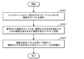
- 11 is a flowchart illustrating an example of a basic decoding process according to an embodiment.
- the three-dimensional mesh is used in computer graphics images.
- the computer graphics images may be composed of a plurality of frames that are temporally different from each other, and each frame may be represented by a three-dimensional mesh.
- a frame represented by a three-dimensional mesh is also referred to as a three-dimensional mesh frame.
- a three-dimensional mesh is composed of vertex information indicating the positions of each of the multiple vertices in three-dimensional space, connection information indicating the connections between the multiple vertices, and attribute information indicating the attributes of each vertex or each face. Each face is constructed according to the connections between the multiple vertices.
- a variety of computer graphic images can be expressed using such three-dimensional meshes.
- the encoding device encodes a displacement vector indicating the amount of deviation in the positions of the vertices of a first 3D mesh and a second 3D mesh.
- the encoding method of Example 1 converts a plurality of displacement vectors indicating a plurality of displacements for correcting a plurality of three-dimensional points included in a three-dimensional mesh frame into a plurality of samples in a predetermined YUV format, and encodes the plurality of samples into a bitstream, the plurality of samples including two or more Y samples corresponding to Y, one or more U samples corresponding to U, and one or more V samples corresponding to V, the two or more Y samples being more than the one or more U samples and more than the one or more V samples.
- the multiple displacement vectors can be converted into multiple samples using a predefined YUV format.
- the multiple displacement vectors can be encoded using a YUV format in which the total number of Y samples is greater than the total number of U samples and greater than the total number of V samples. Using such a YUV format allows for a good balance between the quality of the reconstructed 3D mesh frame and the size of the bitstream.
- the encoding method of Example 2 may be the encoding method of Example 1, in which the plurality of displacement vectors may include a plurality of component values including a component value corresponding to a first axis in a predetermined three-axis coordinate system, a component value corresponding to a second axis different from the first axis, and a component value corresponding to a third axis different from the first axis and the second axis.
- the number of sample types and the number of component values corresponding to each axis in the displacement vector become the same.
- the component values can be converted into samples of the same type and encoded, for example, thereby improving encoding efficiency.
- the encoding method of Example 3 is the encoding method of Example 2, and in the conversion, all of the component values corresponding to the first axis included in each of the plurality of displacement vectors among the plurality of component values may be converted into the Y sample.
- the encoding method of Example 4 is the encoding method of Example 2 or Example 3, and in the conversion, only some of the two or more component values that correspond to the second axis or the third axis and are included in the multiple displacement vectors may be converted into the U sample or the V sample.
- the encoding method of Example 5 is any of the encoding methods of Examples 2 to 4, and the specified YUV format does not have to include the value of the second axis.
- the amount of coding allows the amount of coding to be reduced. Also, for example, when the value of the second axis (i.e., the component value corresponding to the second axis) is close to 0, the amount of coding can be reduced while suppressing any reduction in the quality of the reconstructed 3D mesh frame.
- the encoding method of Example 6 is any of the encoding methods of Examples 2 to 5, and the specified YUV format does not have to include the value of the third axis.
- the amount of coding allows the amount of coding to be reduced. Also, for example, when the value of the third axis (i.e., the component value corresponding to the third axis) is close to 0, the amount of coding can be reduced while suppressing any degradation in the quality of the reconstructed 3D mesh frame.
- the encoding method of Example 7 is any one of the encoding methods of Examples 2 to 6, and the predetermined three-axis coordinate system may be a local coordinate system for each of the multiple three-dimensional points.
- the encoding method of Example 8 is the encoding method of Examples 2 to 6, and the predetermined three-axis coordinate system may be a global coordinate system.
- the encoding method of Example 9 is the encoding method of Examples 1 to 8, and the specified YUV format may be the YUV420 format or the YUV422 format.
- the decoding method of Example 10 decodes a plurality of samples in a predetermined YUV format from a bitstream, converts the decoded plurality of samples into a plurality of displacement vectors indicating a plurality of displacements for correcting a plurality of three-dimensional points, and reconstructs a three-dimensional mesh frame including the plurality of three-dimensional points corrected using the plurality of displacement vectors, the plurality of samples including two or more Y samples corresponding to Y, one or more U samples corresponding to U, and one or more V samples corresponding to V, the two or more Y samples being more than the one or more U samples and more than the one or more V samples.
- samples converted using a predefined YUV format can be converted into displacement vectors.
- the samples can be decoded using a YUV format such that the total number of Y samples is greater than the total number of U samples and greater than the total number of V samples.
- a YUV format allows for a good balance between the quality of the reconstructed 3D mesh frame and the size of the bitstream.
- the decoding method of Example 11 is the decoding method of Example 10, and the plurality of displacement vectors may include a plurality of component values including a component value corresponding to a first axis in a predetermined three-axis coordinate system, a component value corresponding to a second axis different from the first axis, and a component value corresponding to a third axis different from the first axis and the second axis.
- the decoding method of Example 12 is the decoding method of Example 11, and in the conversion, the two or more Y samples may all be converted into component values corresponding to the first axis that are included in each of the plurality of displacement vectors among the plurality of component values.
- the decoding method of Example 13 is the decoding method of Example 11 or Example 12, and the conversion may convert the U sample or the V sample into at least one of the two or more component values corresponding to the second axis or the third axis that are included in the multiple displacement vectors, among the multiple component values.
- the decoding method of Example 14 is any one of the decoding methods of Examples 11 to 13, and in the conversion, one or more of the two or more component values corresponding to the second axis or the third axis that are included in the multiple displacement vectors among the multiple component values and that are not converted in any of the multiple samples may be set to 0.
- the decoding method of Example 15 is any one of the decoding methods of Examples 11 to 14, and the predetermined three-axis coordinate system may be a local coordinate system corresponding to each of the multiple three-dimensional points.
- the decoding method of Example 16 is any one of the decoding methods of Examples 11 to 14, and the predetermined three-axis coordinate system may be a global coordinate system.
- the decoding method of Example 17 is any one of the decoding methods of Examples 10 to 16, and the specified YUV format may be the YUV420 format or the YUV422 format.
- the encoding device of Example 18 includes a memory and a circuitry accessible to the memory, the circuitry being operable to convert a plurality of displacement vectors, indicating a plurality of displacements for correcting a plurality of three-dimensional points included in a three-dimensional mesh frame, into a plurality of samples in a predetermined YUV format, and to encode the plurality of samples into a bitstream, the plurality of samples including two or more Y samples corresponding to Y, one or more U samples corresponding to U, and one or more V samples corresponding to V, the two or more Y samples being greater than the one or more U samples and greater than the one or more V samples.
- the encoding device can convert the multiple displacement vectors into multiple samples using a predetermined YUV format.
- the encoding device can also encode the multiple displacement vectors using a YUV format in which the total number of Y samples is greater than the total number of U samples and greater than the total number of V samples.
- a YUV format By using such a YUV format, it is possible to achieve an appropriate balance between the quality of the reconstructed 3D mesh frame and the size of the bitstream.
- the decoding device of Example 19 includes a memory and a circuitry accessible to the memory, which, in operation, decodes a plurality of samples in a predetermined YUV format from a bitstream, converts the decoded samples into a plurality of displacement vectors indicating a plurality of displacements for correcting a plurality of three-dimensional points, and reconstructs a three-dimensional mesh frame including the plurality of three-dimensional points corrected using the plurality of displacement vectors, the plurality of samples including two or more Y samples corresponding to Y, one or more U samples corresponding to U, and one or more V samples corresponding to V, the two or more Y samples being greater than the one or more U samples and greater than the one or more V samples.
- the decoding device can convert the multiple samples converted using a specific YUV format into multiple displacement vectors.
- the decoding device can also decode the multiple samples using a YUV format in which the total number of Y samples is greater than the total number of U samples and greater than the total number of V samples.
- a YUV format By using such a YUV format, it is possible to achieve an appropriate balance between the quality of the reconstructed 3D mesh frame and the size of the bitstream.
- a three-dimensional mesh is a collection of multiple faces, and represents, for example, a three-dimensional object.
- a three-dimensional mesh is mainly composed of vertex information, connection information, and attribute information.
- a three-dimensional mesh may be expressed as a polygon mesh or a mesh.
- a three-dimensional mesh may have a temporal change.
- a three-dimensional mesh may include metadata related to the vertex information, connection information, and attribute information, and may include other additional information.
- Vertex information is information indicating a vertex.
- the vertex information indicates the position of a vertex in a three-dimensional space.
- the vertex corresponds to the vertex of a face that constitutes a three-dimensional mesh.
- Vertex information may be expressed as "geometry.”
- vertex information may be expressed as position information.
- connection information is information indicating a connection between vertices.
- the connection information indicates a connection for forming a face or an edge of a three-dimensional mesh.
- the connection information may be expressed as "Connectivity.”
- the connection information may also be expressed as face information.
- the attribute information is information indicating attributes of a vertex or a face.
- the attribute information indicates attributes such as a color, an image, and a normal vector associated with a vertex or a face.
- the attribute information may be expressed as "Texture.”
- Faces is an element that constitutes a three-dimensional mesh. Specifically, a face is a polygon on a plane in three-dimensional space. For example, a face can be defined as a triangle in three-dimensional space.
- Plane A plane is a two-dimensional plane in a three-dimensional space.
- a polygon is formed on a plane, and multiple polygons are formed on multiple planes.
- Bitstream corresponds to encoded information.
- a bitstream may also be expressed as a stream, an encoded bitstream, a compressed bitstream, or an encoded signal.
- Encoding and Decoding may be substituted with terms such as storing, including, writing, describing, signaling, sending, notifying, saving, or compressing, and these terms may be substituted with each other.
- encoding information may mean including information in a bitstream.
- encoding information into a bitstream may mean encoding information to generate a bitstream that includes the encoded information.
- decoding information may mean obtaining information from a bitstream.
- Decoding information from a bitstream may mean decoding the bitstream to obtain information contained in the bitstream.
- ordinal numbers such as first and second may be given to components and the like. These ordinal numbers may be changed as appropriate. In addition, new ordinal numbers may be given to components and the like, or ordinal numbers may be removed. In addition, these ordinal numbers may be given to elements in order to identify the elements, and may not correspond to a meaningful order.
- FIG. 1 is a conceptual diagram showing a three-dimensional mesh according to the present embodiment.
- the three-dimensional mesh is composed of a number of faces. For example, each face is a triangle. The vertices of these triangles are defined in three-dimensional space.
- the three-dimensional mesh then represents a three-dimensional object. Each face may have a color or an image.
- FIG. 2 is a conceptual diagram showing the basic elements of a three-dimensional mesh according to this embodiment.
- a three-dimensional mesh is composed of vertex information, connection information, and attribute information.
- the vertex information indicates the positions of the vertices of a face in three-dimensional space.
- the connection information indicates the connections between the vertices.
- a face can be identified by the vertex information and connection information.
- a colorless three-dimensional object is formed in three-dimensional space by the vertex information and connection information.
- Attribute information may be associated with a vertex or with a face. Attribute information associated with a vertex may be expressed as "Attribute Per Point.” Attribute information associated with a vertex may indicate the attributes of the vertex itself, or may indicate the attributes of the face connected to the vertex.
- a color may be associated with a vertex as attribute information.
- the color associated with a vertex may be the color of the vertex, or the color of the face connected to the vertex.
- the color of a face may be the average of multiple colors associated with multiple vertices of the face.
- a normal vector may be associated with a vertex or face as attribute information. Such a normal vector can represent the front and back of a face.
- a two-dimensional image may be associated with a surface as attribute information.
- the two-dimensional image associated with a surface is also expressed as a texture image or an "Attribute Map.”
- information indicating a mapping between the surface and the two-dimensional image may be associated with the surface as attribute information.
- Such information indicating a mapping may be expressed as mapping information, vertex information of a texture image, or "Attribute UV Coordinate.”
- information such as colors, images, and moving images used as attribute information may be expressed as "Parametric Space.”
- This attribute information allows texture to be reflected on the three-dimensional object.
- a three-dimensional object with color is formed in three-dimensional space using vertex information, connection information, and attribute information.
- the attribute information is associated with vertices or faces, but it may also be associated with edges.
- FIG. 3 is a conceptual diagram showing mapping according to this embodiment.
- a region of a two-dimensional image on a two-dimensional plane can be mapped onto a surface of a three-dimensional mesh in three-dimensional space.
- coordinate information of the region in the two-dimensional image is associated with the surface of the three-dimensional mesh. This causes the image of the mapped region in the two-dimensional image to be reflected on the surface of the three-dimensional mesh.
- the two-dimensional image used as attribute information can be separated from the three-dimensional mesh.
- the two-dimensional image may be encoded by an image encoding method or a video encoding method.
- ⁇ System Configuration> 4 is a block diagram showing an example of the configuration of a coding/decoding system according to this embodiment.
- the coding/decoding system includes a coding device 100 and a decoding device 200.
- the encoding device 100 obtains a three-dimensional mesh and encodes the three-dimensional mesh into a bitstream.
- the encoding device 100 then outputs the bitstream to the network 300.
- the bitstream includes the encoded three-dimensional mesh and control information for decoding the encoded three-dimensional mesh.
- the information of the three-dimensional mesh is compressed.
- the network 300 transmits the bit stream from the encoding device 100 to the decoding device 200.
- the network 300 may be the Internet, a wide area network (WAN), a local area network (LAN), or a combination of these.
- the network 300 is not necessarily limited to bidirectional communication, and may be a one-way communication network for terrestrial digital broadcasting, satellite broadcasting, etc.
- the network 300 can also be replaced by a recording medium such as a DVD (Digital Versatile Disc) or a BD (Blu-Ray Disc (registered trademark)).
- a recording medium such as a DVD (Digital Versatile Disc) or a BD (Blu-Ray Disc (registered trademark)).
- the decoding device 200 obtains a bit stream and decodes a three-dimensional mesh from the bit stream. By decoding the three-dimensional mesh, the information of the three-dimensional mesh is expanded. For example, the decoding device 200 decodes the three-dimensional mesh according to a decoding method that corresponds to the encoding method used by the encoding device 100 to encode the three-dimensional mesh. That is, the encoding device 100 and the decoding device 200 perform encoding and decoding according to encoding methods and decoding methods that correspond to each other.
- the 3D mesh before encoding can also be referred to as the original 3D mesh.
- the 3D mesh after decoding can also be referred to as the reconstructed 3D mesh.
- ⁇ Encoding device> 5 is a block diagram showing an example of the configuration of an encoding device 100 according to this embodiment.
- the encoding device 100 includes a vertex information encoder 101, a connection information encoder 102, and an attribute information encoder 103.
- the vertex information encoder 101 is an electrical circuit that encodes vertex information. For example, the vertex information encoder 101 encodes the vertex information into a bit stream according to a format defined for the vertex information.
- connection information encoder 102 is an electrical circuit that encodes the connection information.
- the connection information encoder 102 encodes the connection information into a bit stream according to a format defined for the connection information.
- the attribute information encoder 103 is an electrical circuit that encodes the attribute information. For example, the attribute information encoder 103 encodes the attribute information into a bit stream according to a format defined for the attribute information.
- the vertex information, connection information, and attribute information may be encoded using variable-length coding or fixed-length coding.
- the variable-length coding may correspond to Huffman coding or context-adaptive binary arithmetic coding (CABAC), etc.
- the vertex information encoder 101, the connection information encoder 102, and the attribute information encoder 103 may be integrated. Alternatively, each of the vertex information encoder 101, the connection information encoder 102, and the attribute information encoder 103 may be further subdivided into multiple components.
- FIG. 6 is a block diagram showing another example of the configuration of the encoding device 100 according to this embodiment.
- the encoding device 100 includes a pre-processor 104 and a post-processor 105 in addition to the configuration shown in FIG. 5.
- the preprocessor 104 is an electrical circuit that performs processing before encoding the vertex information, connection information, and attribute information.
- the preprocessor 104 may perform conversion processing, separation processing, multiplexing processing, etc. on the three-dimensional mesh before encoding. More specifically, for example, the preprocessor 104 may separate the vertex information, connection information, and attribute information from the three-dimensional mesh before encoding.
- the post-processor 105 is an electrical circuit that performs processing after the vertex information, connection information, and attribute information are encoded.
- the post-processor 105 may perform conversion processing, separation processing, multiplexing processing, etc. on the encoded vertex information, connection information, and attribute information. More specifically, for example, the post-processor 105 may multiplex the encoded vertex information, connection information, and attribute information into a bit stream. Also, for example, the post-processor 105 may further perform variable-length coding on the encoded vertex information, connection information, and attribute information.
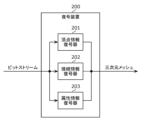
- ⁇ Decoding device> 7 is a block diagram showing an example of the configuration of a decoding device 200 according to this embodiment.
- the decoding device 200 includes a vertex information decoder 201, a connection information decoder 202, and an attribute information decoder 203.
- the vertex information decoder 201 is an electrical circuit that decodes vertex information. For example, the vertex information decoder 201 decodes the vertex information from the bit stream according to a format defined for the vertex information.
- connection information decoder 202 is an electrical circuit that decodes the connection information. For example, the connection information decoder 202 decodes the connection information from the bit stream according to a format defined for the connection information.
- the attribute information decoder 203 is an electrical circuit that decodes the attribute information. For example, the attribute information decoder 203 decodes the attribute information from the bit stream according to a format defined for the attribute information.
- Vertex information, connection information, and attribute information may be decoded using variable length decoding or fixed length decoding.
- Variable length decoding may correspond to Huffman coding or context-adaptive binary arithmetic coding (CABAC), etc.
- the vertex information decoder 201, the connection information decoder 202, and the attribute information decoder 203 may be integrated. Alternatively, each of the vertex information decoder 201, the connection information decoder 202, and the attribute information decoder 203 may be divided into multiple components.
- FIG. 8 is a block diagram showing another example of the configuration of the decoding device 200 according to this embodiment.
- the decoding device 200 includes a pre-processor 204 and a post-processor 205 in addition to the configuration shown in FIG. 7.
- the pre-processor 204 is an electrical circuit that performs processing before the vertex information, connection information, and attribute information are decoded.
- the pre-processor 204 may perform conversion processing, separation processing, multiplexing processing, or the like on the bit stream before the vertex information, connection information, and attribute information are decoded.
- the preprocessor 204 may separate from the bitstream a sub-bitstream corresponding to the vertex information, a sub-bitstream corresponding to the connection information, and a sub-bitstream corresponding to the attribute information. Also, for example, the preprocessor 204 may perform variable length decoding on the bitstream in advance before decoding the vertex information, connection information, and attribute information.
- the post-processor 205 is an electrical circuit that performs processing after the vertex information, connection information, and attribute information are decoded.
- the post-processor 205 may perform conversion processing, separation processing, multiplexing processing, etc. on the decoded vertex information, connection information, and attribute information. More specifically, for example, the post-processor 205 may multiplex the decoded vertex information, connection information, and attribute information into a three-dimensional mesh.
- ⁇ Bitstream> The vertex information, connection information, and attribute information are encoded and stored in a bitstream. The relationship between these pieces of information and the bitstream is shown below.
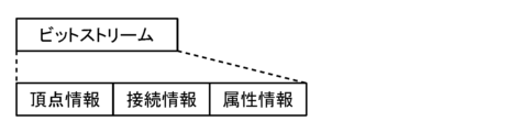
- FIG. 9 is a conceptual diagram showing an example of the configuration of a bitstream according to this embodiment.
- vertex information, connection information, and attribute information are integrated in the bitstream.
- the vertex information, connection information, and attribute information may be included in a single file.
- multiple parts of this information may be stored sequentially, such as a first part of vertex information, a first part of connection information, a first part of attribute information, a second part of vertex information, a second part of connection information, a second part of attribute information, etc. These multiple parts may correspond to multiple parts that are different in time, multiple parts that are different in space, or multiple different faces.
- the order in which the vertex information, connection information, and attribute information are stored is not limited to the above example, and a storage order different from the above example may be used.
- FIG. 10 is a conceptual diagram showing another example of the configuration of a bitstream according to this embodiment.
- multiple files are included in the bitstream, and vertex information, connection information, and attribute information are each stored in different files.
- a file containing vertex information, a file containing connection information, and a file containing attribute information are shown, but the storage format is not limited to this example.
- two types of information out of the vertex information, connection information, and attribute information may be included in one file, and the remaining type of information may be included in another file.
- this information may be split and stored in more files.
- multiple parts of the vertex information may be stored in multiple files
- multiple parts of the connectivity information may be stored in multiple files
- multiple parts of the attribute information may be stored in multiple files. These multiple parts may correspond to multiple parts that are different in time, multiple parts that are different in space, or multiple different faces.
- the order in which the vertex information, connection information, and attribute information are stored is not limited to the above example, and a storage order different from the above example may be used.
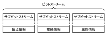
- FIG. 11 is a conceptual diagram showing another example of the configuration of a bitstream according to this embodiment.
- the bitstream is composed of multiple separable sub-bitstreams, and vertex information, connection information, and attribute information are each stored in a different sub-bitstream.
- a sub-bitstream containing vertex information, a sub-bitstream containing connection information, and a sub-bitstream containing attribute information are shown, but the storage format is not limited to this example.
- two types of information among the vertex information, connection information, and attribute information may be included in one sub-bitstream, and the remaining type of information may be included in another sub-bitstream.
- attribute information of a two-dimensional image or the like may be stored in a sub-bitstream that complies with an image coding method, separate from the sub-bitstreams of vertex information and connection information.
- each sub-bitstream may contain multiple files. And, multiple pieces of vertex information may be stored in multiple files, multiple pieces of connectivity information may be stored in multiple files, and multiple pieces of attribute information may be stored in multiple files.
- ⁇ Specific examples> 12 is a block diagram showing a specific example of an encoding/decoding system according to this embodiment.
- the encoding/decoding system includes a three-dimensional data encoding system 110, a three-dimensional data decoding system 210, and an external connector 310.
- the three-dimensional data encoding system 110 comprises a controller 111, an input/output processor 112, a three-dimensional data encoder 113, a three-dimensional data generator 115, and a system multiplexer 114.
- the three-dimensional data decoding system 210 comprises a controller 211, an input/output processor 212, a three-dimensional data decoder 213, a system demultiplexer 214, a presenter 215, and a user interface 216.
- sensor data is input from a sensor terminal to a three-dimensional data generator 115.
- the three-dimensional data generator 115 generates three-dimensional data, such as point cloud data or mesh data, from the sensor data and inputs it to the three-dimensional data encoder 113.
- the three-dimensional data generator 115 generates vertex information, and generates connection information and attribute information corresponding to the vertex information.
- the three-dimensional data generator 115 may process the vertex information when generating the connection information and attribute information.
- the three-dimensional data generator 115 may reduce the amount of data by deleting duplicate vertices, or may transform the vertex information (such as by shifting the position, rotating, or normalizing).
- the three-dimensional data generator 115 may also render the attribute information.
- the three-dimensional data generator 115 is a component of the three-dimensional data encoding system 110 in FIG. 12, it may be located outside the three-dimensional data encoding system 110 independently.
- the sensor terminal that provides the sensor data for generating the three-dimensional data may be, for example, a moving body such as an automobile, a flying object such as an airplane, a mobile terminal, or a camera.
- a distance sensor such as a LIDAR, a millimeter wave radar, an infrared sensor, or a range finder, a stereo camera, or a combination of multiple monocular cameras may be used as the sensor terminal.
- Sensor data may be the distance (position) of the object, monocular camera images, stereo camera images, color, reflectance, sensor attitude, orientation, gyro, sensing position (GPS information or altitude), speed, acceleration, sensing time, temperature, air pressure, humidity, or magnetism, etc.
- the three-dimensional data encoder 113 corresponds to the encoding device 100 shown in FIG. 5 etc.
- the three-dimensional data encoder 113 encodes three-dimensional data to generate encoded data.
- the three-dimensional data encoder 113 also generates control information in encoding the three-dimensional data.
- the three-dimensional data encoder 113 then inputs the encoded data together with the control information to the system multiplexer 114.
- the encoding method for three-dimensional data may be an encoding method that uses geometry, or an encoding method that uses a video codec.
- the encoding method that uses geometry may also be expressed as a geometry-based encoding method.
- the encoding method that uses a video codec may also be expressed as a video-based encoding method.
- the system multiplexer 114 multiplexes the encoded data and control information input from the three-dimensional data encoder 113, and generates multiplexed data using a specified multiplexing method.
- the system multiplexer 114 may multiplex other media such as video, audio, subtitles, application data, or document files, or reference time information, along with the encoded data and control information of the three-dimensional data.
- the system multiplexer 114 may multiplex attribute information related to the sensor data or the three-dimensional data.
- the multiplexed data has a file format for storage, or a packet format for transmission.
- ISOBMFF or a format based on ISOBMFF may be used.
- MPEG-DASH, MMT, MPEG-2 TS Systems, RTP, etc. may be used.
- the multiplexed data is output by the input/output processor 112 to the external connector 310 as a transmission signal.
- the multiplexed data may be transmitted as a transmission signal by wire or wirelessly.
- the multiplexed data is stored in an internal memory or storage device.
- the multiplexed data may be transmitted to a cloud server via the Internet, or may be stored in an external storage device.
- the transmission or storage of the multiplexed data is performed in a manner appropriate to the medium for transmission or storage, such as broadcasting or communication.
- a communication protocol http, ftp, TCP, UDP, IP, or a combination of these may be used.
- a PULL type communication method or a PUSH type communication method may be used.
- Ethernet registered trademark
- USB registered trademark
- RS-232C HDMI (registered trademark), coaxial cable, etc.
- 3GPP registered trademark
- 3G/4G/5G defined by IEEE wireless LAN, Wi-Fi, Bluetooth, or millimeter waves
- wireless LAN wireless local area network
- Wi-Fi wireless local area network
- Bluetooth wireless personal area network
- millimeter waves may be used.
- DVB-T2, DVB-S2, DVB-C2, ATSC3.0, or ISDB-S3 may be used.
- the sensor data may be input to the three-dimensional data generator 115 or the system multiplexer 114.
- the three-dimensional data or encoded data may be output directly as a transmission signal to the external connector 310 via the input/output processor 112.
- the transmission signal output from the three-dimensional data encoding system 110 is input to the three-dimensional data decoding system 210 via the external connector 310.
- each operation of the three-dimensional data encoding system 110 may be controlled by a controller 111 that executes an application program.
- a transmission signal is input to an input/output processor 212.
- the input/output processor 212 decodes multiplexed data having a file format or packet format from the transmission signal, and inputs the multiplexed data to a system demultiplexer 214.
- the system demultiplexer 214 obtains encoded data and control information from the multiplexed data, and inputs them to a three-dimensional data decoder 213.
- the system demultiplexer 214 may extract other media or reference time information from the multiplexed data.
- the three-dimensional data decoder 213 corresponds to the decoding device 200 shown in FIG. 7 etc.
- the three-dimensional data decoder 213 decodes three-dimensional data from the encoded data based on a predefined encoding method.
- the three-dimensional data is then presented to the user by the presenter 215.
- additional information such as sensor data may be input to the presenter 215.
- the presenter 215 may present three-dimensional data based on the additional information.
- a user's instruction may be input from a user terminal to the user interface 216. Then, the presenter 215 may present three-dimensional data based on the input instruction.
- the input/output processor 212 may also obtain the three-dimensional data and encoded data from the external connector 310.
- each operation of the three-dimensional data decoding system 210 may be controlled by a controller 211 that executes an application program.
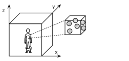
- FIG. 13 is a conceptual diagram showing an example of the configuration of point cloud data according to this embodiment.
- the point cloud data is data of a group of points that represent a three-dimensional object.
- a point cloud is made up of multiple points, and has position information indicating the three-dimensional coordinate position (Position) of each point, and attribute information indicating the attributes (Attribute) of each point. Position information is also expressed as geometry.
- the type of attribute information may be, for example, color or reflectance.
- a single point may be associated with attribute information of one type, a single point may be associated with attribute information of multiple different types, or a single point may be associated with attribute information having multiple values for the same type.
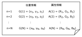
- FIG. 14 is a conceptual diagram showing an example of a data file of point cloud data according to this embodiment.
- the location information is information that indicates a three-dimensional coordinate position using three axes, x, y, and z
- the attribute information is information that indicates a color using RGB.
- a PLY file or the like can be used as a representative data file for point cloud data.
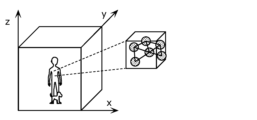
- FIG. 15 is a conceptual diagram showing an example of the configuration of mesh data according to this embodiment.
- Mesh data is data used in CG (Computer Graphics) and the like, and is three-dimensional mesh data that shows the three-dimensional shape of an object with multiple faces. Each face is also expressed as a polygon, and has a polygonal shape such as a triangle or a rectangle.
- a 3D mesh is made up of multiple edges and faces, in addition to multiple points that make up a point cloud.
- Each point is also expressed as a vertex or position.
- Each edge corresponds to a line segment connected by two vertices.
- Each face corresponds to an area surrounded by three or more edges.
- a three-dimensional mesh also has position information indicating the three-dimensional coordinate positions of the vertices.
- the position information is also expressed as vertex information or geometry.
- a three-dimensional mesh also has connection information indicating the relationship between the multiple vertices that make up an edge or face.
- the connection information is also expressed as connectivity.
- a three-dimensional mesh also has attribute information indicating the attributes of the vertices, edges, or faces. The attribute information in a three-dimensional mesh is also expressed as texture.
- attribute information may indicate color, reflectance, or normal vectors for a vertex, edge, or face.
- the orientation of the normal vector may represent the front and back of a face.
- An object file or the like may be used as the data file format for mesh data.
- FIG. 16 is a conceptual diagram showing an example data file of mesh data according to this embodiment.
- the data file contains position information G(1) to G(N) of the N vertices that make up the three-dimensional mesh, and attribute information A1(1) to A1(N) of the N vertices.
- M pieces of attribute information A2(1) to A2(M) are also included.
- the attribute information items do not have to correspond one-to-one to the vertices, and do not have to correspond one-to-one to the faces. Also, the attribute information does not have to exist.
- connection information is represented by a combination of vertex indices.
- attribute information may be recorded in a separate file.
- a pointer to that content may then be associated with a vertex, face, or the like.
- attribute information indicating an image for a face may be stored in a two-dimensional attribute map file.
- the file name of the attribute map and two-dimensional coordinate values in the attribute map may then be recorded in attribute information A2(1)-A2(M).
- the method of specifying attribute information for a face is not limited to these methods, and any method may be used.
- FIG. 17 is a conceptual diagram showing the types of three-dimensional data according to this embodiment.
- the point cloud data and mesh data may represent static objects or dynamic objects.
- a static object is an object that does not change over time
- a dynamic object is an object that changes over time.
- a static object may correspond to three-dimensional data for any point in time.
- PCC frame point cloud data for any point in time
- mesh frame mesh data for any point in time
- PCC frames and mesh frames may simply be referred to as frames.
- the area of the object may be limited to a certain range, as in normal video data, or may not be limited, as in map data.
- the density of points or surfaces may be defined in various ways. Sparse point cloud data or sparse mesh data may be used, or dense point cloud data or dense mesh data may be used.
- the device, process, or syntax for encoding and decoding vertex information of a three-dimensional mesh in this disclosure may be applied to the encoding and decoding of a point cloud.
- the device, process, or syntax for encoding and decoding vertex information of a point cloud in this disclosure may be applied to the encoding and decoding of vertex information of a three-dimensional mesh.
- the device, process, or syntax for encoding and decoding attribute information of a point cloud in the present disclosure may be applied to encoding and decoding connectivity information or attribute information of a three-dimensional mesh.
- the device, process, or syntax for encoding and decoding connectivity information or attribute information of a three-dimensional mesh in the present disclosure may be applied to encoding and decoding attribute information of a point cloud.
- processing may be shared between the encoding and decoding of point cloud data and the encoding and decoding of mesh data. This can reduce the scale of the circuit and software program.
- FIG. 18 is a block diagram showing an example of the configuration of the three-dimensional data encoder 113 according to this embodiment.
- the three-dimensional data encoder 113 includes a vertex information encoder 121, an attribute information encoder 122, a metadata encoder 123, and a multiplexer 124.
- the vertex information encoder 121, the attribute information encoder 122, and the multiplexer 124 may correspond to the vertex information encoder 101, the attribute information encoder 103, and the post-processor 105 in FIG. 6, etc.
- the three-dimensional data encoder 113 encodes the three-dimensional data according to a geometry-based encoding method. Encoding according to the geometry-based encoding method takes into account the three-dimensional structure. Also, encoding according to the geometry-based encoding method encodes attribute information using configuration information obtained in encoding the vertex information.
- the vertex information, attribute information, and metadata contained in the three-dimensional data generated from the sensor data are input to a vertex information encoder 121, an attribute information encoder 122, and a metadata encoder 123, respectively.
- the connection information contained in the three-dimensional data may be treated in the same way as the attribute information.
- the position information may be treated as vertex information.
- the vertex information encoder 121 encodes the vertex information into compressed vertex information and outputs the compressed vertex information to the multiplexer 124 as encoded data.
- the vertex information encoder 121 also generates metadata for the compressed vertex information and outputs it to the multiplexer 124.
- the vertex information encoder 121 also generates configuration information and outputs it to the attribute information encoder 122.
- the attribute information encoder 122 uses the configuration information generated by the vertex information encoder 121 to encode the attribute information into compressed attribute information, and outputs the compressed attribute information as encoded data to the multiplexer 124.
- the attribute information encoder 122 also generates metadata for the compressed attribute information and outputs it to the multiplexer 124.
- the metadata encoder 123 encodes compressible metadata into compressed metadata and outputs the compressed metadata to the multiplexer 124 as encoded data.
- the metadata encoded by the metadata encoder 123 may be used to encode vertex information and attribute information.
- the multiplexer 124 multiplexes the compressed vertex information, the metadata of the compressed vertex information, the compressed attribute information, the metadata of the compressed attribute information, and the compressed metadata into a bitstream.
- the multiplexer 124 then inputs the bitstream to the system layer.
- FIG. 19 is a block diagram showing an example configuration of a three-dimensional data decoder 213 according to this embodiment.
- the three-dimensional data decoder 213 includes a vertex information decoder 221, an attribute information decoder 222, a metadata decoder 223, and a demultiplexer 224.
- the vertex information decoder 221, the attribute information decoder 222, and the demultiplexer 224 may correspond to the vertex information decoder 201, the attribute information decoder 203, and the preprocessor 204 in FIG. 8, etc.
- the three-dimensional data decoder 213 decodes the three-dimensional data according to a geometry-based encoding method.
- the three-dimensional structure is taken into consideration.
- attribute information is decoded using configuration information obtained in decoding the vertex information.
- a bitstream is input from the system layer to the demultiplexer 224.
- the demultiplexer 224 separates compressed vertex information, compressed vertex information metadata, compressed attribute information, compressed attribute information metadata, and compressed metadata from the bitstream.
- the compressed vertex information and compressed vertex information metadata are input to the vertex information decoder 221.
- the compressed attribute information and compressed attribute information metadata are input to the attribute information decoder 222.
- the metadata is input to the metadata decoder 223.
- the vertex information decoder 221 decodes vertex information from the compressed vertex information using metadata of the compressed vertex information.
- the vertex information decoder 221 also generates configuration information and outputs it to the attribute information decoder 222.
- the attribute information decoder 222 decodes attribute information from the compressed attribute information using the configuration information generated by the vertex information decoder 221 and the metadata of the compressed attribute information.
- the metadata decoder 223 decodes metadata from the compressed metadata. The metadata decoded by the metadata decoder 223 may be used to decode the vertex information and the attribute information.
- the vertex information, attribute information, and metadata are output from the 3D data decoder 213 as 3D data.
- this metadata is metadata of the vertex information and attribute information, and can be used in an application program.
- FIG. 20 is a block diagram showing another example of the configuration of the three-dimensional data encoder 113 according to this embodiment.
- the three-dimensional data encoder 113 includes a vertex image generator 131, an attribute image generator 132, a metadata generator 133, a video encoder 134, a metadata encoder 123, and a multiplexer 124.
- the vertex image generator 131, the attribute image generator 132, and the video encoder 134 may correspond to the vertex information encoder 101 and the attribute information encoder 103 in FIG. 6, etc.
- the three-dimensional data encoder 113 encodes the three-dimensional data according to a video-based encoding method.
- a video-based encoding method multiple two-dimensional images are generated from the three-dimensional data, and the multiple two-dimensional images are encoded according to a video encoding method.
- the video encoding method may be HEVC (High Efficiency Video Coding) or VVC (Versatile Video Coding), etc.
- vertex information and attribute information contained in the three-dimensional data generated from the sensor data are input to the metadata generator 133. Furthermore, the vertex information and attribute information are input to the vertex image generator 131 and the attribute image generator 132, respectively. Furthermore, the metadata contained in the three-dimensional data is input to the metadata encoder 123.
- the connection information contained in the three-dimensional data may be treated in the same way as the attribute information. Furthermore, in the case of point cloud data, position information may be treated as vertex information.
- the metadata generator 133 generates map information for multiple two-dimensional images from the vertex information and attribute information.
- the metadata generator 133 then inputs the map information to the vertex image generator 131, the attribute image generator 132, and the metadata encoder 123.
- the vertex image generator 131 generates a vertex image based on the vertex information and map information, and inputs the vertex image to the video encoder 134.
- the attribute image generator 132 generates an attribute image based on the attribute information and map information, and inputs the attribute image to the video encoder 134.
- the video encoder 134 encodes the vertex images and attribute images into compressed vertex information and compressed attribute information, respectively, according to a video encoding method, and outputs the compressed vertex information and compressed attribute information to the multiplexer 124 as encoded data.
- the video encoder 134 also generates metadata for the compressed vertex information and metadata for the compressed attribute information, and outputs them to the multiplexer 124.
- the metadata encoder 123 encodes the compressible metadata into compressed metadata and outputs the compressed metadata to the multiplexer 124 as encoded data.
- the compressible metadata includes map information.
- the metadata encoded by the metadata encoder 123 may also be used to encode vertex information and attribute information.
- the multiplexer 124 multiplexes the compressed vertex information, the metadata of the compressed vertex information, the compressed attribute information, the metadata of the compressed attribute information, and the compressed metadata into a bitstream.
- the multiplexer 124 then inputs the bitstream to the system layer.
- FIG. 21 is a block diagram showing another example configuration of the 3D data decoder 213 according to this embodiment.
- the 3D data decoder 213 includes a vertex information generator 231, an attribute information generator 232, a video decoder 234, a metadata decoder 223, and a demultiplexer 224.
- the vertex information generator 231, the attribute information generator 232, and the video decoder 234 may correspond to the vertex information decoder 201 and the attribute information decoder 203 in FIG. 8, etc.
- the three-dimensional data decoder 213 decodes the three-dimensional data according to a video-based coding method.
- decoding according to the video-based coding method multiple two-dimensional images are decoded according to a video coding method, and three-dimensional data is generated from the multiple two-dimensional images.
- the video coding method may be HEVC (High Efficiency Video Coding) or VVC (Versatile Video Coding), etc.
- the bitstream is input from the system layer to the demultiplexer 224.
- the demultiplexer 224 separates compressed vertex information, compressed vertex information metadata, compressed attribute information, compressed attribute information metadata, and compressed metadata from the bitstream.
- the compressed vertex information, compressed vertex information metadata, compressed attribute information, and compressed attribute information metadata are input to the video decoder 234.
- the compressed metadata is input to the metadata decoder 223.
- the video decoder 234 decodes the vertex image according to the video encoding method. At this time, the video decoder 234 decodes the vertex image from the compressed vertex information using the metadata of the compressed vertex information. Then, the video decoder 234 inputs the vertex image to the vertex information generator 231. Also, the video decoder 234 decodes the attribute image according to the video encoding method. At this time, the video decoder 234 decodes the attribute image from the compressed attribute information using the metadata of the compressed attribute information. Then, the video decoder 234 inputs the attribute image to the attribute information generator 232.
- the metadata decoder 223 decodes metadata from the compressed metadata.
- the metadata decoded by the metadata decoder 223 includes map information used to generate vertex information and attribute information.
- the metadata decoded by the metadata decoder 223 may also be used to decode vertex images and attribute images.
- the vertex information generator 231 reproduces vertex information from the vertex image according to the map information included in the metadata decoded by the metadata decoder 223.
- the attribute information generator 232 reproduces attribute information from the attribute image according to the map information included in the metadata decoded by the metadata decoder 223.
- the vertex information, attribute information, and metadata are output from the 3D data decoder 213 as 3D data.
- this metadata is metadata of the vertex information and attribute information, and can be used in an application program.
- FIG. 22 is a conceptual diagram showing a specific example of the encoding process according to this embodiment.
- FIG. 22 shows a three-dimensional data encoder 113 and a description encoder 148.
- the three-dimensional data encoder 113 includes a two-dimensional data encoder 141 and a mesh data encoder 142.
- the two-dimensional data encoder 141 includes a texture encoder 143.
- the mesh data encoder 142 includes a vertex information encoder 144 and a connection information encoder 145.
- the vertex information encoder 144, the connection information encoder 145, and the texture encoder 143 may correspond to the vertex information encoder 101, the connection information encoder 102, and the attribute information encoder 103 in FIG. 6, etc.
- the two-dimensional data encoder 141 operates as a texture encoder 143 and generates a texture file by encoding the texture corresponding to the attribute information as two-dimensional data according to an image encoding method or a video encoding method.
- the mesh data encoder 142 also operates as a vertex information encoder 144 and a connection information encoder 145, and generates a mesh file by encoding the vertex information and connection information.
- the mesh data encoder 142 may further encode mapping information for a texture. The encoded mapping information may then be included in the mesh file.
- the description encoder 148 also generates a description file by encoding a description that corresponds to metadata such as text data.
- the description encoder 148 may encode the description in the system layer.
- the description encoder 148 may be included in the system multiplexer 114 in FIG. 12.
- the above operations generate a bitstream that includes texture files, mesh files, and description files. These files may be multiplexed into the bitstream in file formats such as glTF (Graphics Language Transmission Format) or USD (Universal Scene Description).
- glTF Graphics Language Transmission Format
- USD Universal Scene Description
- the three-dimensional data encoder 113 may include two mesh data encoders as the mesh data encoder 142.
- one mesh data encoder encodes vertex information and connection information of a static three-dimensional mesh
- the other mesh data encoder encodes vertex information and connection information of a dynamic three-dimensional mesh.
- two mesh files may be included in the bitstream.
- one mesh file corresponds to a static 3D mesh and the other mesh file corresponds to a dynamic 3D mesh.
- the static three-dimensional mesh may be an intraframe three-dimensional mesh encoded using intra-prediction
- the dynamic three-dimensional mesh may be an interframe three-dimensional mesh encoded using inter-prediction
- the information on the dynamic three-dimensional mesh may be differential information between the vertex information or connection information of the intraframe three-dimensional mesh and the vertex information or connection information of the interframe three-dimensional mesh.
- FIG. 23 is a conceptual diagram showing a specific example of the decoding process according to this embodiment.
- FIG. 23 shows a three-dimensional data decoder 213, a description decoder 248, and a presenter 247.
- the three-dimensional data decoder 213 includes a two-dimensional data decoder 241, a mesh data decoder 242, and a mesh reconstructor 246.
- the two-dimensional data decoder 241 includes a texture decoder 243.
- the mesh data decoder 242 includes a vertex information decoder 244 and a connection information decoder 245.
- the vertex information decoder 244, the connection information decoder 245, the texture decoder 243, and the mesh reconstructor 246 may correspond to the vertex information decoder 201, the connection information decoder 202, the attribute information decoder 203, and the post-processor 205 in FIG. 8.
- the presenter 247 may correspond to the presenter 215 in FIG. 12.
- the two-dimensional data decoder 241 operates as a texture decoder 243, and decodes the texture corresponding to the attribute information from the texture file as two-dimensional data according to an image encoding method or a video encoding method.
- the mesh data decoder 242 also operates as a vertex information decoder 244 and a connection information decoder 245, and decodes vertex information and connection information from the mesh file.
- the mesh data decoder 242 may further decode mapping information for textures from the mesh file.
- the description decoder 248 also decodes a description corresponding to metadata such as text data from the description file.
- the description decoder 248 may decode the description at the system layer.
- the description decoder 248 may be included in the system demultiplexer 214 of FIG. 12.
- the mesh reconstructor 246 reconstructs a three-dimensional mesh from vertex information, connectivity information, and textures according to the description.
- the presenter 247 renders and outputs the three-dimensional mesh according to the description.
- the three-dimensional data decoder 213 may include two mesh data decoders as the mesh data decoder 242. For example, one mesh data decoder decodes vertex information and connection information of a static three-dimensional mesh, and the other mesh data decoder decodes vertex information and connection information of a dynamic three-dimensional mesh.
- two mesh files may be included in the bitstream.
- one mesh file corresponds to a static 3D mesh and the other mesh file corresponds to a dynamic 3D mesh.
- the static three-dimensional mesh may be an intraframe three-dimensional mesh encoded using intra-prediction
- the dynamic three-dimensional mesh may be an interframe three-dimensional mesh encoded using inter-prediction
- the information on the dynamic three-dimensional mesh may be differential information between the vertex information or connection information of the intraframe three-dimensional mesh and the vertex information or connection information of the interframe three-dimensional mesh.
- the dynamic 3D mesh coding method is sometimes called DMC (Dynamic Mesh Coding). Also, the video-based dynamic 3D mesh coding method is sometimes called V-DMC (Video-based Dynamic Mesh Coding).
- the point cloud coding method is sometimes called PCC (Point Cloud Compression).
- PCC Point Cloud Compression
- V-PCC Video-based Point Cloud Compression
- G-PCC Geometry-based Point Cloud Compression
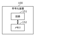
- Fig. 24 is a block diagram showing an implementation example of the encoding device 100 according to this embodiment.
- the encoding device 100 includes a circuit 151 and a memory 152.
- a plurality of components of the encoding device 100 shown in Fig. 5 and the like are implemented by the circuit 151 and the memory 152 shown in Fig. 24.
- Circuit 151 is a circuit that performs information processing and is capable of accessing memory 152.
- circuit 151 is a dedicated or general-purpose electric circuit that encodes a three-dimensional mesh.
- Circuit 151 may be a processor such as a CPU.
- Circuit 151 may also be a collection of multiple electric circuits.
- Memory 152 is a dedicated or general-purpose memory in which information for circuit 151 to encode the three-dimensional mesh is stored.
- Memory 152 may be an electric circuit and may be connected to circuit 151.
- Memory 152 may also be included in circuit 151.
- Memory 152 may also be a collection of multiple electric circuits.
- Memory 152 may also be a magnetic disk or an optical disk, etc., and may also be expressed as storage or recording medium, etc.
- Memory 152 may also be a non-volatile memory or a volatile memory.
- the memory 152 may store a three-dimensional mesh or a bitstream.
- the memory 152 may also store a program for the circuit 151 to encode the three-dimensional mesh.
- the multiple components shown in FIG. 5 and the like do not have to be implemented, and all of the multiple processes shown here do not have to be performed. Some of the multiple components shown in FIG. 5 and the like may be included in another device, and some of the multiple processes shown here may be executed by another device. Furthermore, in the encoding device 100, the multiple components of the present disclosure may be implemented in any combination, and the multiple processes of the present disclosure may be performed in any combination.
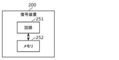
- FIG. 25 is a block diagram showing an implementation example of the decoding device 200 according to this embodiment.
- the decoding device 200 includes a circuit 251 and a memory 252.
- the multiple components of the decoding device 200 shown in FIG. 7 and the like are implemented by the circuit 251 and memory 252 shown in FIG. 25.
- Circuit 251 is a circuit that performs information processing and is capable of accessing memory 252.
- circuit 251 is a dedicated or general-purpose electric circuit that decodes a three-dimensional mesh.
- Circuit 251 may be a processor such as a CPU.
- Circuit 251 may also be a collection of multiple electric circuits.
- Memory 252 is a dedicated or general-purpose memory that stores information for circuit 251 to decode the three-dimensional mesh.
- Memory 252 may be an electric circuit and may be connected to circuit 251. Memory 252 may also be included in circuit 251. Memory 252 may also be a collection of multiple electric circuits. Memory 252 may also be a magnetic disk or an optical disk, etc., and may also be expressed as storage or recording medium, etc. Memory 252 may also be a non-volatile memory or a volatile memory.
- the memory 252 may store a three-dimensional mesh or a bitstream.
- the memory 252 may also store a program for the circuit 251 to decode the three-dimensional mesh.
- the decoding device 200 all of the multiple components shown in FIG. 7 etc. do not have to be implemented, and all of the multiple processes shown here do not have to be performed. Some of the multiple components shown in FIG. 7 etc. may be included in another device, and some of the multiple processes shown here may be executed by another device. Furthermore, in the decoding device 200, the multiple components of the present disclosure may be implemented in any combination, and the multiple processes of the present disclosure may be performed in any combination.
- the encoding method and the decoding method including the steps performed by each component of the encoding device 100 and the decoding device 200 of the present disclosure may be executed by any device or system.
- a part or all of the encoding method and the decoding method may be executed by a computer including a processor, a memory, an input/output circuit, etc.
- the encoding method and the decoding method may be executed by the computer executing a program for causing the computer to execute the encoding method and the decoding method.
- program or the bitstream may be recorded on a non-transitory computer-readable recording medium such as a CD-ROM.
- An example of a program may be a bitstream.
- a bitstream including an encoded three-dimensional mesh includes syntax elements for causing the decoding device 200 to decode the three-dimensional mesh.
- the bitstream then causes the decoding device 200 to decode the three-dimensional mesh in accordance with the syntax elements included in the bitstream.
- the bitstream may play a role similar to that of a program.
- the bitstream may be an encoded bitstream containing the encoded 3D mesh, or it may be a multiplexed bitstream containing the encoded 3D mesh and other information.
- each component of the encoding device 100 and the decoding device 200 may be configured with dedicated hardware, or may be configured with general-purpose hardware that executes the above-mentioned programs, etc., or may be configured with a combination of these.
- the general-purpose hardware may be configured with a memory in which the program is recorded, and a general-purpose processor that reads and executes the program from the memory, etc.
- the memory may be a semiconductor memory or a hard disk, etc.
- the general-purpose processor may be a CPU, etc.
- the dedicated hardware may be configured with a memory and a dedicated processor, etc.
- the dedicated processor may execute the encoding method and the decoding method by referring to a memory for recording data.
- each component of the encoding device 100 and the decoding device 200 may be an electric circuit, as described above. These electric circuits may form a single electric circuit as a whole, or each may be a separate electric circuit. Furthermore, these electric circuits may correspond to dedicated hardware, or may correspond to general-purpose hardware that executes the above-mentioned programs, etc. Furthermore, the encoding device 100 and the decoding device 200 may be implemented as an integrated circuit.
- the encoding device 100 may be a transmitting device that transmits the three-dimensional mesh.
- the decoding device 200 may be a receiving device that receives the three-dimensional mesh.
- the present disclosure can be used for encoding and decoding any multimedia data related to a 3D digital representation of any object or surface in computer graphics applications.
- the present disclosure can be used to encode a static or dynamic 3D model represented by a triangular mesh.
- a typical 3D model represents an object digitally, allowing a user to explore the model by zooming, panning, and rotating in all three dimensions while temporarily rendering the 3D model.
- One way to build such a representation is to build a 3D mesh using triangles.
- the 3D model stores the positions of the triangle vertices, the connectivity of the triangles to each other, and the attributes associated with the triangles (such as normals and UV patches). Storing all this information in an uncompressed format would require very large storage space, and transmitting all this information would require very high bandwidth.
- the triangles that form the mesh often have repeating patterns and similar attributes, especially in temporal and spatial neighborhoods. These repetitions can be used to formulate efficient encoding and decoding methods for storage and transmission.
- FIG. 26 shows the configuration of an encoding/decoding system according to this embodiment.
- the encoding/decoding system shown in FIG. 26 obtains a 3D mesh frame (input 3D mesh frame) that includes vertex geometry coordinates, texture coordinates, and connectivity data.
- the encoding/decoding system includes an encoding device 100 and a decoding device 200.
- the encoding device 100 encodes all relevant information into a bitstream (compressed bitstream).
- the compressed bitstream may be composed of multiple bitstreams.
- the bitstream is output to the decoding device 200 via a transmission path.
- the decoding device 200 decodes the bitstream and generates (reconstructs) a 3D mesh frame using the decoded vertex geometry coordinates, texture coordinates, and connectivity data.
- FIG. 27 shows an example of the configuration of an encoding device 100 according to this embodiment.
- the encoding device 100 includes a volumetric capturer 511, a projector 512, a base mesh encoder 513, a displacement encoder 514, an attribute encoder 515, and an other type encoder 516.
- the volumetric capturer 511 captures the content and outputs the captured content to the projector 512.
- the projector 512 projects the content onto a 3D mesh frame.
- the 3D mesh frame includes vertex geometry coordinates, texture coordinates, and connectivity data. That is, the projector 512 generates vertex geometry coordinates, texture coordinates, and connectivity data based on the content.
- the projector 512 outputs the vertex geometry coordinates, texture coordinates, and connectivity data to the base mesh encoder 513, the displacement encoder 514, the attribute encoder 515, and the other type encoder 516, which is an encoder different from these encoders.
- the encoding device 100 may or may not include the other type encoder 516.
- Each encoder encodes each data into a bit stream. In other words, a bit stream including each encoded data is generated by each encoder. The generated bit stream is transmitted to the decoding device 200.
- FIG. 28 shows another example of the configuration of the encoding device 100 according to this embodiment.
- the encoding device 100 includes a preprocessor 521 and an encoding processor 522.
- the preprocessor 521 acquires a three-dimensional mesh frame.
- the preprocessor 521 processes the acquired three-dimensional mesh frame to extract a base mesh, displacement information, and an attribute map.
- the preprocessor 521 also outputs the extracted information to the encoding processor 522.
- An example of the displacement information is a displacement vector.
- the encoding processor 522 encodes and multiplexes the information extracted by the preprocessor 521. Specifically, the encoding processor 522 encodes the base mesh, the displacement information, and the attribute map separately, and generates a bitstream by combining each piece of encoded information (for example, by multiplexing each piece of encoded information). The generated bitstream is transmitted to the decoding device 200.
- FIG. 29 shows an example of the configuration of a decoding device 200 according to this embodiment.
- the decoding device 200 includes a base mesh decoder 613, a displacement decoder 614, an attribute decoder 615, and an other type decoder 616.
- the bitstream transmitted from the encoding device 100 is output to a base mesh decoder 613, a displacement decoder 614, an attribute decoder 615, and an other type decoder 616, which is a decoder different from these decoders.
- the decoding device 200 may or may not include the other type decoder 616.
- Each decoder decodes the bitstream to generate decoded data including vertex geometry coordinates, texture coordinates, and connectivity.
- the decoded data is output to a 3D reconstructor 617.
- the 3D reconstructor 617 generates (reconstructs) a 3D mesh frame based on the decoded data, including vertex geometry coordinates, texture coordinates, and connectivity.
- FIG. 30 shows another example of the configuration of the decoding device 200 according to this embodiment.
- the decoding device 200 includes a decoding processor 622 and a post-processor 623.
- the decoding processor 622 obtains a bitstream.
- the decoding processor 622 also performs demultiplexing and decoding of the output bitstream. Specifically, the decoding processor 622 first separates the encoded base mesh, the encoded displacement information, and the encoded attribute map from the bitstream and decodes them individually. Next, the decoding processor 622 outputs the decoded information to the post-processor 623.
- An example of the displacement information is a displacement vector.
- the post-processor 623 processes the base mesh according to the displacement information and the attribute map to generate a 3D mesh frame.
- FIG. 31 is a diagram showing yet another example of the configuration of the decoding device 200 according to this embodiment. Specifically, FIG. 31 shows an example of the main configuration of a vertex geometry coordinate decoder included in the decoding device 200.
- the vertex geometry coordinate decoder included in the decoding device 200 includes, for example, a frame header decoder 641, a vertex geometry coordinate predictor 642, a vertex geometry coordinate difference decoder 643, and a reconstruction module 644.
- the frame header decoder 641 decodes the header of the bitstream and determines whether to perform intra-decoding or inter-decoding on the frame data contained in the bitstream.
- the frame data in the bitstream is output to a vertex geometry coordinate predictor 642, which outputs prediction information.
- the vertex geometry coordinate predictor 642 generates prediction information based on frame data in the bitstream and outputs the generated prediction information to the reconstruction module 644.
- prediction information is motion prediction information (e.g., motion vectors).
- the reconstruction module 644 outputs the vertex geometry coordinates using the prediction information output from the vertex geometry coordinate predictor 642 together with the vertex geometry coordinates obtained from the previously decoded frame (3D mesh frame).
- the frame data in the bitstream is output to the vertex geometry coordinate difference decoder 643.
- the vertex geometry coordinate difference decoder 643 decodes the frame data that has been encoded as the differences between vertex geometry coordinates within a frame to generate vertex geometry coordinates.
- FIG. 32 is a conceptual diagram showing an example of subdivision according to this embodiment. Specifically, FIG. 32 is a diagram for explaining the main processing steps for deriving new vertices from existing vertices using subdivision.
- the base mesh (basic three-dimensional mesh frame) shown in FIG. 32 includes vertices A, B, and C and their connectivity.
- vertices D, E, and F and their connectivity are determined.
- Vertices D, E, and F and their connectivity are derived by adding new vertices between the already connected vertices A-B, B-C, and C-D. These newly added vertices and their connectivity, together with the existing vertices and connectivity, form LoD (Level of Detail) 1.
- vertices G, H, I, J, K, L, M, N, and O and their connectivity are derived by a similar process to the above process, forming LoD2.
- FIG. 33 is a diagram showing yet another example of the configuration of the decoding device 200 according to this embodiment. Specifically, FIG. 33 shows an example of the main configuration of a displacement decoder included in the decoding device 200. For example, the displacement decoder 614 shown in FIG. 29 includes the components shown in FIG. 33.
- the displacement decoder of the decoding device 200 includes, for example, a video decoder 631, an image decompressor 632, an inverse quantizer 633, and an inverse wavelet transformer 634.
- the video decoder 631 obtains a bitstream.
- the video decoder 631 assumes that the bitstream is an image having two pieces of chroma information and one piece of luma information.
- the video decoder 631 decodes the data contained in the bitstream using a predetermined video decoding method. This decoded data is output to the image decompressor 632.
- the image decompressor 632 extracts wavelet coefficients associated with each vertex from the decoded (decompressed) data in image format.
- the image decompressor 632 outputs the extracted wavelet coefficients to the inverse quantizer 633.
- the inverse quantizer 633 performs inverse quantization of the quantized wavelet coefficients of the three components associated with each vertex.
- the inverse quantizer 633 outputs the results to the inverse wavelet transformer 634.
- the inverse wavelet transformer 634 performs an inverse transform (inverse wavelet transform) on the execution result output from the inverse quantizer 633. As a result, the inverse wavelet transformer 634 obtains final decoded displacement information.
- the inverse wavelet transformer 634 outputs the decoded displacement information to, for example, the 3D reconstructor 617.
- An example of the displacement information is a displacement vector. This decoded displacement information is used to displace vertices in a 3D mesh frame.
- Another approach is to use the YUV400 format for encoding.
- this encoding for example, one of the three components included in all three-dimensional displacement vectors (for example, only the normal component in the local coordinate system) is encoded as a luminance component and output. Therefore, for example, in this encoding, two of the three components (for example, the tangent component and the bi-tangential component in the local coordinate system) are discarded without being encoded. Therefore, this encoding can save the size of the bit stream.
- the three-dimensional mesh frame reconstructed based on the bit stream generated by this encoding may be distorted and its quality may be low. Also, it may not be possible to decode it on hardware that does not support the YUV400 format.
- the above method has the problem that it is difficult to achieve a good balance between the processing time (runtime) of the 3D mesh frame, the quality of the reconstructed 3D mesh frame, and the size of the bitstream.
- the YUV420 format is used, in which the chrominance components (U, V) are a quarter of the size of the luminance component (Y).
- the YUV420 format is more commonly used than formats such as YUV444 and YUV400, and more hardware supports the YUV420 format.
- a good balance can be achieved between the processing time of the 3D mesh frame, the quality of the reconstructed 3D mesh frame, and the size of the bitstream. Therefore, better encoding may be achieved.
- the YUV420 format it is necessary to fill in missing values of the displacement vector.
- FIG. 34 is a diagram for explaining the conversion of the components of a displacement vector in a local coordinate system when the YUV420 format is used. Specifically, FIG. 34 is a diagram for explaining the problem that the YUV420 format cannot fill in the components of a displacement vector in a local coordinate system.
- the components of the displacement vectors shown in FIG. 34 correspond to, for example, three axes in a local coordinate system.
- the three axes in the local coordinate system are, for example, the normal axis (hereinafter also simply referred to as the N-axis), the tangent axis (hereinafter also simply referred to as the T-axis), and the bitangent axis (hereinafter also simply referred to as the B-axis).
- N-axis normal axis
- T-axis tangent axis
- B-axis bitangent axis
- each component of the coordinate system represented by the N-axis, T-axis, and B-axis may be generated by converting each component of the displacement vector represented by the components of another coordinate system used to express the vertex positions of the mesh based on the normal vector.
- the other coordinate system used to express the vertex positions of the mesh may be called a global coordinate system, or it may be a coordinate system used to define the normal vector.
- the displacement vector may be directly derived from each component of the coordinate system represented by the N-axis, T-axis, and B-axis using the vertex positions of the base mesh or the vertex positions derived using the base mesh, the mesh to be encoded, and the normal vector.
- the three components (hereinafter also referred to as component values) corresponding to the displacement vector are the component corresponding to the N-axis (hereinafter also referred to as the N component), the component corresponding to the T-axis (hereinafter also referred to as the T component), and the component corresponding to the B-axis (hereinafter also referred to as the B component).
- N component the component corresponding to the N-axis
- T component the component corresponding to the T-axis
- B component corresponding to the B component hereinafter also referred to as the B component.
- the decoding device 200 can calculate the N component of the four displacement vectors from a to d.
- the decoding device 200 cannot calculate the T and B components of the four displacement vectors from the values e and f of the remaining two samples. Therefore, for example, in the present application, the components of the displacement vector expressed in the global coordinate system or the local coordinate system are determined during decoding using data decoded from the bit stream.
- each sample is generated according to the dominant characteristics of the components of the displacement vector.
- the N-axis component is usually higher than the T-axis and B-axis components.
- the T and B components each have a value close to 0.
- the displacement vector indicates, for example, the displacement of the vertex position.
- the displacement in the normal direction (N-axis direction) of the surface formed by the lines connecting the vertices shown in FIG. 32 is represented by the N-component of the displacement vector.
- the vertex position is particularly likely to be displaced in the N-axis direction of the surface than in the T and B axes. Therefore, for example, four samples are assigned to represent the N-axis component, and the other two samples are assigned to represent the T and B axis components.
- This approach can also be applied when the displacement vector is expressed in a coordinate system other than a local coordinate system, such as a global coordinate system.
- Such an approach allows the use of the main coding profile that is widely available on digital devices such as laptops, mobile phones, and tablets. It also allows the bitstream size to be reduced. It also allows the impact on the objective and subjective quality of the reconstructed 3D mesh frame to be reduced.
- ⁇ Encoding of Displacement Vector> 35 is a flowchart showing the encoding process (mesh encoding process) according to this embodiment.
- the encoding device 100 performs each process shown in FIG.
- each of the four displacement vectors includes three components.
- Each component of the displacement vector represents a difference in one of the axes of the second coordinate system between a first vertex in the first three-dimensional mesh frame and a second vertex in the second three-dimensional mesh frame.
- the first three-dimensional mesh frame is, for example, a three-dimensional mesh frame after the position of the vertex is corrected by the displacement vector.
- the second three-dimensional mesh frame is, for example, a three-dimensional mesh frame before the position of the vertex is corrected by the displacement vector. That is, the first three-dimensional mesh frame is, for example, a second three-dimensional mesh frame corrected using the displacement vector.
- the first vertex is, for example, a vertex after the position is corrected by the displacement vector.
- the second vertex is, for example, a vertex before the position is corrected by the displacement vector. That is, the first vertex is, for example, a second vertex corrected using the displacement vector.
- the four displacement vectors may be determined arbitrarily and are not particularly limited.
- the displacement vectors may be calculated from multiple three-dimensional mesh frames, or may be included in the three-dimensional mesh frame into which information indicating the displacement vectors is input.
- the encoding device 100 converts the four displacement vectors into six samples (S102). Specifically, the encoding device 100 converts a total of 12 components contained in the four displacement vectors into six samples. That is, the encoding device 100 reduces the total number of pieces of information from 12 to six.
- the four samples represent the difference in the first axis of the three axes in the first coordinate system, and the other two samples represent the difference in an axis other than the first axis in the first coordinate system.
- the first coordinate system and the second coordinate system may be any coordinate system.
- the first coordinate system and the second coordinate system may be the same coordinate system or different coordinate systems.
- the first coordinate system and the second coordinate system are, for example, a local coordinate system or a global coordinate system.
- the first axis is, for example, the N axis.
- the first axis may be the T axis or the N axis.
- the encoding device 100 encodes the six samples into a bitstream (S103). In other words, the encoding device 100 generates a bitstream including the six samples. The encoding device 100 transmits the generated bitstream to the decoding device 200, for example.
- step S101 four sets of displacement vectors are derived between the first mesh frame and the second mesh frame.
- Each set of displacement vectors has three components.
- the displacement vectors represent the difference between a first vertex of the first 3D mesh frame and a second vertex of the second 3D mesh frame.
- the four displacement vectors are converted into six samples by directly copying the components of the displacement vector. That is, for example, the components (component values) of the displacement vector become samples (sample values).
- the encoding device 100 may use values obtained by quantizing or wavelet transforming the components of the displacement vector as samples. Using the components of the displacement vector as samples as they are, or using a transform such as quantization or wavelet transform to use the components as samples, is also referred to as simply converting (or sampling) the components into samples. Similarly, using the samples as components of the displacement vector as they are, or using a transform such as inverse quantization or inverse wavelet transform to use the samples as components, is also referred to simply converting (inverse transforming) the samples into components.
- the six samples are encoded into a bitstream using a video codec (video encoding standard).
- video codec video encoding standard
- the encoding device 100 encodes the six samples according to a video encoding standard.
- Any codec may be used to encode the samples into a bitstream.
- the video encoding standard include existing video encoding standards such as High Efficiency Video Codec (HEVC), Versatile Video Coding (VVC), or any custom arithmetic coding.
- the displacement vector is expressed, for example, using the N-axis, T-axis, and B-axis (local coordinate system).
- the N-axis, T-axis, and B-axis may be replaced with the x-axis, y-axis, and z-axis (global coordinate system), or other three-axis coordinate system.
- an axis corresponding to a component that is dominant compared to the components corresponding to the other two axes e.g., a component whose value is greater than the other components
- a sample may be determined based on two axes that correspond to a component that is dominant compared to the components corresponding to the other axes.
- the specific numerical value adopted as the dominant value may be determined arbitrarily.
- FIG. 36 is a diagram for explaining the components of displacement vectors and samples according to this embodiment.
- N1, N2, N3, and N4 indicate the components corresponding to the N-axis direction of each of the four displacement vectors.
- T1, T2, T3, and T4 indicate the components corresponding to the T-axis direction of each of the four displacement vectors.
- B1, B2, B3, and B4 indicate the B-axis components of each of the four displacement vectors.
- the N-axis, T-axis, and B-axis are examples of the first axis, second axis, and third axis.
- the components of the N, T and B axes are associated to form vectors as follows:
- the values of N1, T1 and B1 are associated to form a vector (first displacement vector).
- the values of N2, T2 and B2 are associated to form a vector (second displacement vector).
- the values of N3, T3 and B3 are associated to form a vector (third displacement vector).
- the values of N4, T4 and B4 are associated to form a vector (fourth displacement vector).
- each vector is (N component, T component, B component)
- the first displacement vector (N1, T1, B1)
- the second displacement vector (N2, T2, B2)
- the third displacement vector (N3, T3, B3)
- the fourth displacement vector (N4, T4, B4).
- the encoding device 100 determines a sample (first sample) with a value of a, a sample (second sample) with a value of b, a sample (third sample) with a value of c, and a sample (fourth sample) with a value of d corresponding to Y (luminance component), a sample (fifth sample) with a value of e corresponding to U (chrominance component), and a sample (sixth sample) with a value of f corresponding to V (chrominance component).
- the samples corresponding to Y (in this example, the first to fourth samples) are also referred to as Y samples.
- the sample corresponding to U in this example, the fifth sample
- U sample is also referred to as U sample.
- the sample corresponding to V is also referred to as V sample.
- each component i.e., the position of the sample to which the component is transformed
- each sample i.e., the position of the sample to which the component is transformed
- At least one of the four displacement vectors is converted into six samples.
- each N component of the four displacement vectors is converted into a first sample to a fourth sample in one-to-one correspondence.
- the encoding device 100 converts N1 into the first sample, N2 into the second sample, N3 into the third sample, and N4 into the fourth sample.
- e and f are values that are determined based on the values of either the T component or the B component in the four displacement vectors.
- FIG. 37 is a diagram showing a first example of the correspondence between components of a displacement vector and samples in this embodiment. Specifically, FIG. 37 shows an example in which the fifth sample (U sample) and the sixth sample (V sample) are associated with the same sample among the four samples (Y samples) corresponding to the N axis. The same sample may be any sample.
- this example is advantageous when one of the four displacement vectors contains more dominant (important) components than the other displacement vectors.
- the fifth and sixth samples are used to encode each component of the one displacement vector.
- the one displacement vector is encoded using three samples, and each of the remaining three displacement vectors is encoded using one sample and only one component.
- FIG. 38 is a diagram showing a second example of the correspondence between the components of a displacement vector and samples according to this embodiment. Specifically, FIG. 38 shows an example in which the fifth and sixth samples are associated with two different samples out of the four samples corresponding to the N axis. Each of the two different samples may be any sample.
- two of the four displacement vectors are coded using two samples each, and the remaining two displacement vectors are coded using one sample each.
- This example has an advantage when the T and B components are each dominant components in different displacement vectors.
- components of different vectors and different axes are used for the fifth and sixth samples.
- FIG. 39 is a diagram showing a third example of the correspondence between the components of a displacement vector and samples in this embodiment.
- FIG. 40 is a diagram showing a fourth example of the correspondence between the components of a displacement vector and samples in this embodiment.
- FIGS. 39 and 40 show an example in which the fifth and sixth samples are associated with only one sample corresponding to the N axis. This one sample may be any sample.
- two of the four displacement vectors are coded using two samples each, and the remaining two displacement vectors are coded using one sample each.
- the T components converted into the fifth and sixth samples are any of the four T components.
- the remaining components that were not converted by the encoding device 100 are considered to be 0 in the decoding device 200.
- components of different vectors and components of the same axis are used for the fifth and sixth samples.
- the encoding device 100 does not convert the remaining components that were not used, and the decoding device 200 converts e, which is the value of the fifth sample, to B1 and f, which is the value of the sixth sample, to B4.
- the decoding device 200 regards the remaining components that were not used as 0, for example. In this example, the decoding device 200 sets T1, T2, T3, T4, B2, and B3 to 0.
- the B component converted into the fifth and sixth samples is one of the four B components.
- the remaining components that were not converted by the encoding device 100 are considered to be 0 in the decoding device 200.
- FIG. 41 is a diagram showing a fifth example of the correspondence between the components of a displacement vector and samples according to this embodiment.
- FIG. 42 is a diagram showing a sixth example of the correspondence between the components of a displacement vector and samples according to this embodiment.
- FIGS. 41 and 42 show an example in which the fifth and sixth samples are associated with two samples corresponding to the N axis.
- the two samples may be any samples.
- the fifth and sixth samples use components on the same axis.
- the encoding device 100 converts T1 or T3, at least one of which has a value of e, into the fifth sample.
- the encoding device 100 converts T2 or T4, at least one of which has a value of f, into the sixth sample.
- the decoding device 200 converts the value of the fifth sample, e, into T1 and T3, converts the value of the sixth sample, f, into T2 and T4, and sets B1, B2, B3, and B4 to 0.
- the T component is converted into the fifth and sixth samples.
- the T component converted into the fifth and sixth samples becomes one of the four T components. Also, in this example, the fifth and sixth samples are converted (copied) into the T component that was not converted into a sample.
- the B component is regarded as 0 in the decoding device 200.
- the fifth and sixth samples use components on the same axis.
- the encoding device 100 converts B1 or B2, at least one of which has a value of e, into the fifth sample.
- the encoding device 100 converts B3 or B4, at least one of which has a value of f, into the sixth sample.
- the decoding device 200 converts the value e of the fifth sample into B1 and B2, converts the value f of the sixth sample into B3 and B4, and sets T1, T2, T3, and T4 to 0.
- T1, T2, T3, and T4 sets T1, T2, T3, and T4 to 0.
- the B component converted into the fifth and sixth samples becomes one of the four B components. Also, in this example, the fifth and sixth samples are converted (copied) into the B component that was not converted into a sample.
- the B component is regarded as 0 in the decoding device 200.
- FIG. 43 is a diagram showing a seventh example of the correspondence between the components of a displacement vector and samples according to this embodiment. Specifically, FIG. 43 shows an example in which the fifth and sixth samples are related to four samples corresponding to the N axis. The four samples may be any samples.
- FIG. 44 is a diagram showing an eighth example of the correspondence between the components of a displacement vector and samples according to this embodiment. Specifically, FIG. 44 shows an example in which the fifth and sixth samples are related to three samples corresponding to the N axis. The three samples may be any samples.
- the encoding device 100 averages the T components or B components and converts the averaged value into the fifth sample or the sixth sample.
- the encoding device 100 converts e, which is the average value of T1 to T4, into the fifth sample. Also, in this example, the encoding device 100 converts f, which is the average value of B1 to B4, into the sixth sample. Also, in this example, the decoding device 200 converts e, which is the value of the fifth sample, into T1 to T4, and converts f, which is the value of the sixth sample, into B1 to B4.
- the encoding device 100 converts e, which is the average value of T2 to T4, into the fifth sample. Also in this example, the encoding device 100 converts f, which is the average value of B1 to B3, into the sixth sample. Also in this example, the decoding device 200 converts e, which is the value of the fifth sample, into T2 to T4, converts f, which is the value of the sixth sample, into B1 to B3, and sets T1 and B4 to 0.
- the fifth and sixth samples are duplicated and converted into four T components and four B components, respectively.
- the fifth and sixth samples are duplicated and converted into three T components and three B components, respectively.
- the remaining one T component and one B component are regarded as 0 in the decoding device 200.
- FIG. 45 is a diagram showing a ninth example of the correspondence between the components of a displacement vector and samples according to this embodiment. Specifically, FIG. 45 shows an example in which the fifth sample is related to one of the four samples corresponding to the N axis, and the sixth sample is related to the remaining three of the four samples corresponding to the N axis.
- the sample corresponding to the N axis to which the fifth and sixth samples are related may be any sample.
- the fifth sample is converted into a T component
- the sixth sample is replicated and converted into three B components each.
- the remaining three T components and the remaining B component are considered to be 0 in the decoding device 200.
- FIG. 46 is a diagram showing the positions of parameters in the header of a bitstream according to this embodiment.
- FIG. 47 is a diagram showing a tenth example of the correspondence between components of a displacement vector and samples according to this embodiment. Specifically, FIG. 47 is a diagram showing an example of two other samples (a Y sample and a U sample) associated with two of the four N samples.
- the method of converting the four displacement vectors into six samples is determined by a parameter, and the parameter is coded into the bitstream. As shown in FIG. 46, the parameter is notified, for example, in the header of the bitstream.
- the parameter defines the method of converting the six samples into four displacement vectors. For example, the U sample and the V sample are each associated with one of the four N samples. As shown in FIG. 47, the six samples are converted into four displacement vectors of (a, 0, 0), (b, e, 0), (c, 0, f), and (d, 0, 0).
- the four displacement vectors of (a, 0, 0), (b, e, 0), (c, 0, f), and (d, 0, 0) are converted into the six samples shown in FIG. 47.
- the conversion between components and samples may be performed in a manner other than the correspondence between components and samples shown in FIG. 47.
- One example of converting (arranging) the six samples is to select to code the dominant value in the coding device 100. For example, using the example shown in Figure 47, when each non-zero value is the dominant value, the bitstream size can be reduced while minimizing the objective quality loss.
- FIG. 48 shows an example of signaling parameters according to this embodiment. Note that n indicates the total number of ways to convert four displacement vectors into six samples.
- FIG. 48 shows an example in which a lookup table is used to refer to a method for converting four displacement vectors into six samples.
- the above parameters are indexes.
- the value 1 in the lookup table indicates the position where the fifth sample and the sixth sample are converted (placed).
- the first sample to the fourth sample are assumed to correspond to N1, N2, N3, and N4. Therefore, in this example, the correspondence between the first sample to the fourth sample and the components is not shown in the lookup table. Of course, the correspondence between the first sample to the fourth sample and the components may be shown in the lookup table.
- FIG. 49 shows a first example of signaling parameters in a header according to this embodiment.
- the parameters include a set of 12 syntax statements.
- FIG. 50 shows a second example of signaling parameters in a header according to this embodiment.
- FIG. 51 shows an example of converting six samples into four displacement vectors in a three-axis coordinate system according to this embodiment.
- the parameters include a set of eight syntax elements.
- the 0th to 3rd positions e.g., N1 to N4 are always coded, and the 4th to 11th positions (e.g., T1 to T4, B1 to B4) are assumed to refer to samples (sample 0 to sample 5) that fill the positions of the three-axis coordinate system shown in Figure 51.
- component_value[0] 4 indicates that the 4th position of the first displacement vector (specifically, the 4th position shown in Figure 51) is the value of sample 4.
- the encoding device 100 can include a format signal in the header of the bit stream that defines the method of encoding the displacement vector. For example, based on the format signal, the encoding device 100 switches the method of encoding (converting) the displacement vector to one of (i) a method of converting all components of the displacement vector, (ii) a method of converting only N components, or (iii) the method of the present application.
- the format signal is set to (i) above, the encoding device 100 operates in the YUV444 format.
- the format signal is set to (ii) above, the encoding device 100 operates in the YUV400 format.
- the format signal is set to (iii) above, the encoding device 100 operates in the YUV420 format.
- the format signal may also be used to determine whether or not the parameters are included in the bitstream. For example, if the format signal is set to (iii) above, the parameters are encoded into the bitstream. On the other hand, for example, if the format signal is set to a method other than (iii) above, the parameters are not encoded into the bitstream.
- the encoding of the parameters may be independent of the format signal.
- FIG. 52 is a block diagram showing yet another example of the configuration of the encoding device 100 according to this embodiment.
- the encoding device 100 is configured to encode an input 3D mesh frame (input 3D mesh frame) and generate a bit stream (output bit stream) including the encoded 3D mesh frame. As shown in FIG. 52, the encoding device 100 includes a deriver 701, a converter 702, and an entropy encoder 703.
- the deriver 701 derives four displacement vectors. In other words, the deriver 701 executes step S101.
- the converter 702 converts the four displacement vectors into six samples. That is, the converter 702 executes step S102.
- the entropy encoder 703 encodes the six samples into a bitstream. That is, the entropy encoder 703 executes step S103.
- a 3D mesh frame is input to the deriver 701.
- the input 3D mesh frame may consist of vertices, connectivity, and attributes to be encoded.
- the deriver 701 derives four sets of displacement vectors, where each set of displacement vectors includes three components. Each component of the displacement vector represents a difference in one of the axes of the second coordinate system between a first vertex in the first 3D mesh frame and a second vertex in the second 3D mesh frame.
- the transformer 702 transforms the four sets of displacement vectors into six samples.
- the components of the displacement vector may be quantized or wavelet transformed before being transformed into six samples.
- the entropy encoder 703 encodes information such as the six samples and outputs the resulting bitstream (encoded bitstream).
- an existing video codec such as HEVC, VVC, or any custom arithmetic coding may be used for encoding.
- the displacement vector may be expressed using the N, T, and B axes (local coordinate system).
- the N, T, and B axes may be replaced by the x, y, and z axes (global coordinate system), or other types of three-axis coordinate systems.
- a component corresponding to an axis having a dominant value compared to the components corresponding to the other two axes is signaled.
- each component corresponding to two axes having a dominant value compared to the components corresponding to the other axes is signaled. As shown in FIG.
- the components of the N, T, and B axes are associated to form a displacement vector as follows: The values of N1, T1, and B1 are associated to form a first displacement vector; The values of N2, T2, and B2 are associated to form a second displacement vector; The values of N3, T3, and B3 are associated to form a third displacement vector; and The values of N4, T4, and B4 are associated to form a fourth displacement vector.
- the converter 702 encodes each component of the displacement vector so that the components of the displacement vector can be filled in by the decoding device 200, even if, for example, a YUV420 format is used.
- Decoding the Displacement Vector 53 is a flowchart showing the decoding process according to this embodiment.
- the decoding device 200 performs each process shown in FIG.
- the decoding device 200 decodes six samples from the bitstream (S201). For example, the decoding device 200 acquires a bitstream from the encoding device 100, and acquires six samples contained in the acquired bitstream. Of the six samples, four samples represent a difference on a first axis of three axes in a first coordinate system. Also, of the six samples, the other two samples represent a difference on an axis different from the first axis of the first coordinate system.
- the decoding device 200 transforms (inverse transforms) the six decoded samples into four displacement vectors (S202), where each of the four displacement vectors includes three components, each component of each displacement vector representing the difference in one of the axes of the second coordinate system between a first vertex in the first 3D mesh frame and a second vertex in the second 3D mesh frame.
- the decoding device 200 reconstructs (generates) a first 3D mesh frame using at least four displacement vectors (S203).
- the first 3D mesh frame is reconstructed by displacing the vertices of the second 3D mesh frame using at least four displacement vectors.
- step S201 six samples are decoded from the bitstream using, for example, a video codec.
- the video codec used to decode the samples from the bitstream may be any video codec.
- the video codec may be, for example, an existing video codec such as HEVC, VVC, or any custom arithmetic decoding.
- step S202 the six samples are converted into a set of four displacement vectors, for example by directly copying values from the samples to the components of the displacement vectors.
- the six samples may be inverse quantized or inverse wavelet transformed before being converted into the components of the displacement vectors.
- step S203 for example, only one vertex of the second three-dimensional mesh frame is displaced using each of the four displacement vectors.
- the four displacement vectors may be equal, and the first three-dimensional mesh frame may be reconstructed by displacing all vertices in the second three-dimensional mesh frame using one of the four displacement vectors.
- the displacement vector may be represented using the N, T and B axes (local coordinate system).
- the N, T and B axes may be replaced by the x, y and z axes (global coordinate system) or other types of three-axis coordinate systems.
- the components corresponding to the axis having a dominant value compared to the components corresponding to the other two axes are signaled.
- the components corresponding to the two axes having a dominant value compared to the components corresponding to the other axes are signaled. As shown in FIG.
- N1, T1 and B1 are associated to form a first displacement vector
- the values of N2, T2 and B2 are associated to form a second displacement vector
- the values of N3, T3 and B3 are associated to form a third displacement vector
- the values of N4, T4 and B4 are associated to form a fourth displacement vector.
- This disclosure proposes several patterns for filling each component of the displacement vector when the YUV420 format is used in step S202.
- Figure 37 shows an example in which the fifth sample (value e) and the sixth sample (value f) are associated with the same sample in a number of samples (specifically, four Y samples corresponding to the N component) corresponding to the first axis (in this example, the N axis).
- the same sample can be any one sample corresponding to the first axis.
- FIG. 38 shows an example in which the fifth and sixth samples are associated with two different samples in the plurality of samples corresponding to the first axis.
- the two different samples may be any two of the plurality of samples corresponding to the first axis.
- the two displacement vectors are each decoded using two samples, and the remaining displacement vectors are each decoded using one sample. This example is advantageous when each component corresponding to the T or B axis is part of a different displacement vector, and each of the different displacement vectors has one dominant component.
- Figures 39 and 40 show an example in which the fifth and sixth samples, which are samples corresponding to the same axis, are each associated with only one sample among the multiple samples corresponding to the first axis.
- the samples corresponding to the first axis associated with the fifth and sixth samples may be any samples. This example is advantageous when the components corresponding to one of the T and B axes are more dominant than the components corresponding to the other axis, and only the two components corresponding to that one axis are decoded.
- FIGS. 41 and 42 show an example in which the fifth and sixth samples corresponding to the same axis are associated with two samples corresponding to the first axis. Note that the samples corresponding to the first axis associated with the fifth and sixth samples may be arbitrary. This example is advantageous when the components corresponding to one of the T and B axes are more dominant than the components corresponding to the other axis, and the four components corresponding to the one axis are sampled into two samples.
- FIG. 44 shows an example in which the fifth and sixth samples corresponding to different axes are associated with three samples corresponding to the first axis.
- the samples corresponding to the first axis associated with the fifth and sixth samples may be any.
- FIG. 43 shows an example in which the fifth and sixth samples corresponding to different axes are associated with four samples corresponding to the first axis.
- the samples corresponding to the first axis associated with the fifth and sixth samples may be any.
- These examples are applied when the components of the T axis or B axis have similar values.
- the encoding device 100 outputs the fifth or sixth sample obtained by averaging the components corresponding to the T axis or B axis.
- the decoding device 200 determines the component corresponding to the T axis or B axis using the fifth or sixth sample obtained by averaging the components corresponding to the T axis or B axis.
- FIG. 45 shows an example in which the fifth sample corresponding to the second axis is associated with the sample corresponding to the first axis, and the sixth sample corresponding to the third axis is associated with three of the four samples corresponding to the first axis.
- the samples corresponding to the first axis associated with the fifth and sixth samples may be arbitrary.
- the method of converting the four displacement vectors into six samples is determined by a parameter, and the parameter is decoded from the bitstream.
- the parameter may be notified in the header of the bitstream.
- the other two samples specifically, the U sample and the V sample
- the six samples are each associated with one of the four samples (specifically, the four Y samples).
- the six samples are converted into four sets of displacement vectors, (a, 0, 0), (b, e, 0), (c, 0, f), and (d, 0, 0).
- the six samples may be converted into a different set of four displacement vectors by arranging them in each component of the displacement vector in a manner other than the above.
- the six samples may be arranged by the decoding device 200 selecting to decode a dominant value.
- the arrangement is obtained and decoded in the decoding device 200.
- the example shown in Figure 47 is effective in reducing the size of the bitstream while minimizing the objective quality loss when each non-zero value is the dominant value.
- Figure 48 shows an example of using a lookup table to look up how to convert four displacement vectors to six samples (or in other words, how to convert six samples to four displacement vectors).
- the parameter is an index.
- a value of 1 in the lookup table indicates where the fifth and sixth samples are located, respectively. In this example, assume that the first four samples are for N1, N2, N3, and N4.
- Figure 49 shows an example of signaling parameters in the header.
- the parameters include a set of 12 syntax elements.
- Each syntax element points to a sample (0-5) that fills a position in the three-axis coordinate system shown in Figure 51.
- component_value[0] 0 indicates that the 0th position of the first displacement vector is filled with the value of sample 0.
- Figure 50 shows an example of signaling parameters in the header.
- the parameters include a set of eight syntax elements.
- the 0th to 3rd positions of the displacement vector shown in Figure 51 are always coded.
- the 4th to 11th positions of the displacement vector shown in Figure 51 refer to samples (0 to 5) that fill the positions of the three-axis coordinate system in Figure 51.
- the encoding device 100 includes a format signal in the bitstream header that defines how to decode the displacement vector. Based on the format signal, the decoding device 200 switches between applying samples to a three-dimensional displacement vector (i.e., all components included in the displacement vector), a normal-only displacement vector (i.e., only N components included in the displacement vector), and a displacement vector according to the method of the present disclosure (i.e., components determined by the above method).
- the format signal is set to a three-dimensional displacement vector
- the decoding device 200 operates in the YUV444 format.
- the decoding device 200 operates in the YUV400 format.
- the decoding device 200 operates in the YUV420 format.
- the format signal may determine whether the parameter is present in the bitstream. For example, if the format signal is set to a displacement vector according to the method of the present disclosure, the parameter is decoded. On the other hand, for example, if the format signal is set to another method, the parameter is not decoded.
- the decoding of parameters may be independent of the format signal.
- FIG. 54 is a block diagram showing yet another example of the configuration of the decoding device 200 according to this embodiment.
- the decoding device 200 is configured to decode an input bitstream (input coded bitstream) and output a mesh geometry (three-dimensional mesh frame). As shown in FIG. 54, the decoding device 200 includes an entropy decoder 801, a transformer 802, and a reconstructor 803.
- the entropy decoder 801 decodes six samples from the bitstream. That is, the entropy decoder 801 executes step S201.
- the converter 802 converts the six decoded samples into four displacement vectors. That is, the converter 802 executes step S202.
- the reconstructor 803 reconstructs the first 3D mesh frame using at least four displacement vectors. That is, the reconstructor 803 executes step S203.
- the input bitstream is input to the entropy decoder 801.
- the video codec used to decode the samples from the bitstream may be any video codec.
- an existing video codec such as HEVC, VVC, or any custom arithmetic coding is used as the video codec.
- the transformer 802 transforms the decoded six samples into a set of four displacement vectors by directly copying the components of the displacement vectors from the samples. Each set of displacement vectors has three components.
- the six samples may be inverse quantized or inverse wavelet transformed before being transformed into the components of the displacement vectors.
- the reconstructor 803 reconstructs the first three-dimensional mesh frame by displacing only one vertex of the second three-dimensional mesh frame using each of the four displacement vectors. Note that the four sets of displacement vectors may be equal, and the reconstructor 803 may displace all vertices in the second 3D mesh frame using one of the four displacement vectors to reconstruct the first 3D mesh frame.
- the displacement vector may be represented using the N, T and B axes (local coordinate system).
- the N, T and B axes may be replaced by the x, y and z axes (global coordinate system) or other types of three-axis coordinate systems.
- the components corresponding to the axis having a dominant value compared to the components corresponding to the other two axes are signaled.
- the components corresponding to the two axes having a dominant value compared to the components corresponding to the other axes are signaled. As shown in FIG.
- N1, T1 and B1 are associated to form a first displacement vector
- the values of N2, T2 and B2 are associated to form a second displacement vector
- the values of N3, T3 and B3 are associated to form a third displacement vector
- the values of N4, T4 and B4 are associated to form a fourth displacement vector.
- the converter 802 compensates for some components of the displacement vector, even if each component of the displacement vector is encoded using, for example, the YUV420 format.
- the encoding process of the position information of three-dimensional points described in each of the embodiments of the present disclosure can be applied to encoding the position information of three-dimensional points in a point cloud compression method such as video-based PCC (V-PCC) or geometry-based PCC (G-PCC).
- V-PCC video-based PCC
- G-PCC geometry-based PCC
- this disclosure discloses a configuration for encoding only some of the coordinates that make up multiple displacement vectors when encoding the displacement vectors of a three-dimensional mesh. For example, this disclosure discloses a configuration for encoding only 6 samples out of the 12 samples when four displacement vectors corresponding to four vertices that make up a three-dimensional mesh each have a total of 12 sample values.
- four of the six samples correspond to the same component, and the other two of the six samples correspond to a component different from the four samples.
- the coordinates corresponding to one of the three components are encoded, and the coordinates corresponding to the remaining two components are generated based on the encoded sample and parameters, etc.
- four samples of the 12 samples corresponding to the same component and only one sample corresponding to another component may be encoded.
- four samples of the 12 samples corresponding to the same component and only three samples corresponding to another component may be encoded.
- four samples of the 12 samples corresponding to the same component and only four samples corresponding to another component may be encoded.
- encoding may be performed using the YUV422 format.
- the four vertices to which the displacement vector to be encoded corresponds may belong to the same object.
- the four vertices may belong to the same frame.
- the four vertices may have connectivity that connects them to each other.
- at least one of the four vertices may constitute the same mesh.
- the four vertices may belong to the same plane.
- the configuration of the present disclosure may be applied to encoding the coordinates of vectors other than displacement vectors.
- Figures 46 to 51 above disclose examples of indexes or parameters that indicate the correspondence between the encoded samples and each component of the displacement vector.
- the index or parameter may be coded in any of the picture header, slice header, CTU (coding tree unit) header, and CU (coding unit) header.
- the index or parameter may also be coded in any of the VPS (video parameter set), SPS (sequence parameter set), PPS (picture parameter set), and SEI (supplemental enhancement information).
- the index may include a value indicating that none of the values of T1 to T4 and B1 to B4 are coded. Alternatively, if none of the values of T1 to T4 and B1 to B4 are coded, the index may not be coded. Alternatively, if none of the values of T1 to T4 and B1 to B4 are coded, the value of the index may be 0. Alternatively, the value of the index may be specified in correspondence with the value of another coding parameter. Alternatively, the possible values of the index may be limited in correspondence with the value of another coding parameter. If the coding device 100 does not code any of the values of T1 to T4 and B1 to B4, the U sample and the V sample may be set to any value.
- the decoding device 200 may regard T1 to T4 and B1 to B4 as 0 regardless of the values of the U sample and the V sample. Also, for example, the coding device 100 may set the values of the U sample and the V sample to 0 regardless of the values of T1 to T4 and B1 to B4.
- component_value[i] may be reduced in bit amount by allowing it to take only values of 0 or 1 as one bit of u(1).
- a value of 0 may correspond to sample 4 in FIG. 51, and a value of 1 may correspond to sample 5.
- component_value[i] may contain a value indicating that the values of the T and B components are 0. Alternatively, if the values of the T and B components are 0, component_value[i] may not need to be coded.
- step S102 when converting from 12 samples to 6 samples, in addition to direct copying, which involves copying and using the values as is, values that have been subjected to some kind of calculation, such as the average, maximum, or minimum value, may also be used.
- the 3D mesh frame may include a base mesh and displacement information.
- the displacement information may be applied to the base mesh to reconstruct the 3D mesh frame. This disclosure can reduce the complexity of a video decoder.
- a mesh encoding method comprising the steps of: deriving (S101) four displacement vectors, each of the four displacement vectors having three components, each of the four displacement vectors representing a difference between a first vertex in the first 3D mesh frame and a second vertex in the second 3D mesh frame in one of a plurality of axes of a second coordinate system; Transforming the four displacement vectors into six samples (S102), where four samples represent a difference in a first axis of three axes in a first coordinate system and the other two samples represent a difference in an axis different from the first axis of the three axes in the first coordinate system; Encoding the six samples into a bitstream (S103); Mesh coding methods.
- the first coordinate system and the second coordinate system are different coordinate systems.
- the mesh coding method according to technique 1.
- the video codec is HEVC (High Efficiency Video Coding) or VVC (Versatile Video Coding), The mesh encoding method according to technology 6.
- the arithmetic coding is a delta coding.
- the first coordinate system or the second coordinate system is a global coordinate system.
- the mesh coding method according to technique 1.
- the first coordinate system or the second coordinate system is a local coordinate system.
- the mesh coding method according to technique 1.
- a mesh decoding method comprising: Decoding six samples from a bitstream (S201), where four of the six samples represent a difference in a first axis of three axes in a first coordinate system and two other samples represent a difference in an axis different from the first axis of three axes in the first coordinate system; converting the six decoded samples into four displacement vectors (S202), each of the four displacement vectors having three components, each component of the four displacement vector representing a difference between a first vertex in the first 3D mesh frame and a second vertex in the second 3D mesh frame in one of a plurality of axes of a second coordinate system; reconstructing the first 3D mesh frame using at least the four displacement vectors (S203), the first 3D mesh frame being reconstructed by displacing vertices of the second 3D mesh frame using at least the four displacement vectors; Mesh decoding method.
- the first coordinate system and the second coordinate system are different coordinate systems.
- the video codec is HEVC (High Efficiency Video Coding) or VVC (Versatile Video Coding), The mesh decoding method according to technique 20.
- the arithmetic coding is a delta coding. 23. The mesh decoding method according to claim 22.
- the first coordinate system or the second coordinate system is a global coordinate system.
- the first coordinate system or the second coordinate system is a local coordinate system.
- a mesh encoding device comprising: deriving (S101) four displacement vectors, each of the four displacement vectors having three components, each of the four displacement vectors representing a difference between a first vertex in the first 3D mesh frame and a second vertex in the second 3D mesh frame in one of a plurality of axes of a second coordinate system; Transforming the four displacement vectors into six samples (S102), where four samples represent a difference in a first axis of three axes in a first coordinate system and the other two samples represent a difference in an axis different from the first axis of three axes in the first coordinate system; Encoding the six samples into a bitstream (S103); Mesh Encoder.
- the first coordinate system and the second coordinate system are the same coordinate system.
- the first coordinate system and the second coordinate system are different coordinate systems.
- 30. The mesh encoding apparatus according to claim 29.
- the video codec is HEVC (High Efficiency Video Coding) or VVC (Versatile Video Coding), The mesh encoding device according to technique 34.
- the arithmetic coding is a delta coding.
- the first coordinate system or the second coordinate system is a global coordinate system.
- 30. The mesh encoding apparatus according to claim 29.
- the first coordinate system or the second coordinate system is a local coordinate system.
- 30. The mesh encoding apparatus according to claim 29.
- a mesh decoding device comprising: Decoding six samples from a bitstream (S201), where four of the six samples represent a difference in a first axis of three axes in a first coordinate system and the other two samples represent a difference in an axis different from the first axis of three axes in the first coordinate system; converting the six decoded samples into four displacement vectors (S202), each of the four displacement vectors having three components, each component of the four displacement vector representing a difference between a first vertex in the first 3D mesh frame and a second vertex in the second 3D mesh frame in one of a plurality of axes of a second coordinate system; reconstructing the first 3D mesh frame using at least the four displacement vectors (S203), the first 3D mesh frame being reconstructed by displacing vertices of the second 3D mesh frame using at least the four displacement vectors; Mesh decoder.
- the first coordinate system and the second coordinate system are different coordinate systems. 44.
- the video codec is HEVC (High Efficiency Video Coding) or VVC (Versatile Video Coding), 49.
- a mesh decoding device according to claim 48.
- the arithmetic coding is a delta coding. 51.
- the first coordinate system or the second coordinate system is a global coordinate system. 44.
- the first coordinate system or the second coordinate system is a local coordinate system.
- Fig. 55 is a flow chart showing an example of a basic encoding process according to this embodiment.
- the circuit 151 of the encoding device 100 shown in Fig. 24 performs the encoding process shown in Fig. 55 in operation.
- the encoding device 100 converts a plurality of displacement vectors indicating a plurality of displacements for correcting a plurality of three-dimensional points included in a three-dimensional mesh frame into a plurality of samples in a predetermined YUV format (S301).
- the plurality of displacement vectors are, for example, the four displacement vectors described above.
- the predetermined YUV format is, for example, the YUV422 format described above.
- the plurality of samples are, for example, the six samples (first sample to sixth sample) described above. Note that the number of the plurality of displacement vectors and the plurality of samples is not particularly limited.
- the plurality of displacement vectors each include three components (component values) as described above.
- the total number of component values of the plurality of displacement vectors is, for example, less than the total number of the plurality of samples.
- the component values of the displacement vector may be copied as is as described above, or the component values may be subjected to processing such as quantization.
- the encoding device 100 encodes the multiple samples into a bitstream (S302). Specifically, the encoding device 100 generates multiple bitstreams including the multiple samples.
- the multiple samples include two or more Y samples corresponding to Y, one or more U samples corresponding to U, and one or more V samples corresponding to V. Furthermore, the two or more Y samples are more than the one or more U samples and are more than the one or more V samples.
- the multiple displacement vectors can be converted into multiple samples using a predefined YUV format.
- the multiple displacement vectors can be encoded using a YUV format in which the total number of Y samples is greater than the total number of U samples and greater than the total number of V samples. Using such a YUV format allows for a good balance between the quality of the reconstructed 3D mesh frame and the size of the bitstream.
- the multiple displacement vectors may include multiple component values including a component value corresponding to a first axis in a predetermined three-axis coordinate system, a component value corresponding to a second axis different from the first axis, and a component value corresponding to a third axis different from the first and second axes.
- the predetermined three-axis coordinate system is, for example, the above-mentioned local coordinate system (a coordinate system consisting of an N axis, a T axis, and a B axis).
- the component value corresponding to the first axis is the value of the N component
- the component value corresponding to the second axis is the value of the T component
- the component value corresponding to the third axis is the value corresponding to the B component.
- the number of sample types and the number of component values corresponding to each axis in the displacement vector become the same.
- the component values can be converted into samples of the same type and encoded, for example, thereby improving encoding efficiency.
- all of the component values corresponding to the first axis included in each of the multiple displacement vectors may be converted into two or more Y samples.
- only some of the two or more component values corresponding to the second or third axis included in the multiple displacement vectors may be converted into one or more U samples or one or more V samples.
- a given YUV format may not include values for the second axis.
- the multiple samples do not have to include a sample in which the component value corresponding to the second axis has been converted.
- the above conversion does not have to convert the component value corresponding to the second axis into a sample. This makes it possible to reduce the amount of coding. Also, for example, when the value of the second axis (i.e., the component value corresponding to the second axis) is close to 0, it is possible to reduce the amount of coding while suppressing any reduction in the quality of the reconstructed 3D mesh frame.
- a given YUV format may not include a third axis value.
- the multiple samples do not have to include a sample in which the component value corresponding to the third axis has been converted.
- the above conversion does not have to convert the component value corresponding to the third axis into a sample. This makes it possible to reduce the amount of coding.
- the value of the third axis i.e., the component value corresponding to the third axis
- the specified three-axis coordinate system may be a local coordinate system for each of the multiple three-dimensional points.
- the specified three-axis coordinate system may be a global coordinate system.
- the specified YUV format may be YUV420 format or YUV422 format.
- FIG. 56 is a flowchart showing an example of a basic decoding process according to this embodiment.
- the circuit 251 of the decoding device 200 shown in FIG. 25 performs the decoding process shown in FIG. 56 in operation.
- the decoding device 200 decodes a number of samples in a predetermined YUV format from the bitstream (S401).
- the decoding device 200 converts the decoded samples into displacement vectors indicating displacements for correcting three-dimensional points (S402).
- the samples may be copied as is as described above, or the samples may be subjected to processing such as inverse quantization.
- processing such as inverse quantization.
- the decoding device 200 reconstructs a 3D mesh frame including the multiple 3D points corrected using the multiple displacement vectors (S402). For example, the decoding device 200 generates a 3D mesh frame by correcting the positions of the multiple 3D points based on the multiple displacement vectors.
- the multiple samples include two or more Y samples corresponding to Y, one or more U samples corresponding to U, and one or more V samples corresponding to V, and the two or more Y samples are more than the one or more U samples and are more than the one or more V samples.
- samples converted using a predefined YUV format can be converted into displacement vectors.
- the samples can be decoded using a YUV format such that the total number of Y samples is greater than the total number of U samples and greater than the total number of V samples.
- a YUV format allows for a good balance between the quality of the reconstructed 3D mesh frame and the size of the bitstream.
- the multiple displacement vectors may include multiple component values including a component value corresponding to a first axis in a predetermined three-axis coordinate system, a component value corresponding to a second axis different from the first axis, and a component value corresponding to a third axis different from the first axis and the second axis.
- two or more Y samples may all be converted into component values corresponding to the first axis that are included in each of the multiple displacement vectors among the multiple component values.
- one or more U samples or one or more V samples may be converted into at least one of two or more component values corresponding to the second axis or the third axis included in the multiple displacement vectors among the multiple component values.
- one or more component values that are included in the multiple displacement vectors and correspond to the second axis or the third axis and that are not converted in any of the multiple samples may be set to 0.
- the specified three-axis coordinate system may be a local coordinate system corresponding to each of multiple three-dimensional points.
- the specified three-axis coordinate system may be a global coordinate system.
- the specified YUV format may be YUV420 format or YUV422 format.
- a process executed by a specific component may be executed by another component instead of the specific component.
- the order of multiple processes may be changed, and multiple processes may be executed in parallel.
- the encoding and decoding of the present disclosure can be applied to the encoding and decoding of displacement vectors.
- the encoding and decoding of the present disclosure is not limited to displacement vectors, and may also be applied to the encoding and decoding of other vectors.
- each process of the present disclosure may be performed as one of multiple selectable processes.
- At least a portion of the configurations of the present disclosure may be implemented as an integrated circuit. At least a portion of the processes of the present disclosure may be used as an encoding method or a decoding method.
- a program for causing a computer to execute the encoding method or the decoding method may be used.
- a non-transitory computer-readable recording medium on which the program is recorded may be used.
- a bitstream for causing the decoding device 200 to perform the decoding process may be used.
- At least a portion of the configurations and processes of the present disclosure may be used as a transmitting device, a receiving device, a transmitting method, and a receiving method.
- a program for causing a computer to execute the transmitting method or the receiving method may be used.
- a non-transitory computer-readable recording medium on which the program is recorded may be used.
- the present disclosure is useful, for example, for encoding devices, decoding devices, transmitting devices, and receiving devices related to three-dimensional meshes, and is applicable to computer graphics systems and three-dimensional data display systems, etc.
Landscapes
- Engineering & Computer Science (AREA)
- Physics & Mathematics (AREA)
- Multimedia (AREA)
- General Physics & Mathematics (AREA)
- Theoretical Computer Science (AREA)
- Signal Processing (AREA)
- Computer Graphics (AREA)
- Geometry (AREA)
- Software Systems (AREA)
- Compression Or Coding Systems Of Tv Signals (AREA)
Abstract
Description
例えば、三次元メッシュは、コンピュータグラフィックス映像に用いられる。例えば、コンピュータグラフィックス映像は、時間的に互いに異なる複数のフレームで構成され、各フレームが三次元メッシュによって表現されてもよい。三次元メッシュで表現されるフレームは、三次元メッシュフレームとも表現される。
ここでは、以下のような表現及び用語が用いられる。
三次元メッシュは、複数の面の集合であり、例えば、三次元物体を示す。また、三次元メッシュは、主に、頂点情報、接続情報及び属性情報で構成される。三次元メッシュは、ポリゴンメッシュ又はメッシュと表現される場合がある。また、三次元メッシュは、時間的な変化を有していてもよい。三次元メッシュは、頂点情報、接続情報及び属性情報に関するメタデータを含んでいてもよいし、その他の付加情報を含んでいてもよい。
頂点情報は、頂点(Vertex)を示す情報である。例えば、頂点情報は、三次元空間における頂点の位置を示す。また、頂点は、三次元メッシュを構成する面の頂点に対応する。頂点情報は、「Geometory(ジオメトリ)」と表現される場合がある。また、頂点情報は、位置情報と表現される場合もある。
接続情報は、頂点間の接続を示す情報である。例えば、接続情報は、三次元メッシュの面又は辺を構成するための接続を示す。接続情報は、「Connectivity(コネクティビティ)」と表現される場合がある。また、接続情報は、面情報と表現される場合もある。
属性情報は、頂点又は面の属性を示す情報である。例えば、属性情報は、頂点又は面に対応付けられる色、画像及び法線ベクトル等の属性を示す。属性情報は、「Texture(テクスチャ)」と表現される場合がある。
面は、三次元メッシュを構成する要素である。具体的には、面は、三次元空間における平面上のポリゴンである。例えば、面は、三次元空間における三角形として定められ得る。
平面は、三次元空間における二次元平面である。例えば、平面上にポリゴンが形成され、複数の平面上に複数のポリゴンが形成される。
ビットストリームは、符号化された情報に対応する。ビットストリームは、ストリーム、符号化ビットストリーム、圧縮ビットストリーム、又は、符号化信号とも表現され得る。
符号化するという表現は、格納する、含める、書き込む、記述する、信号化する、送り出す、通知する、保存する、又は、圧縮する等の表現に置き換えられてもよく、これらの表現が相互に置き換えられてもよい。例えば、情報を符号化することは、ビットストリームに情報を含めることであってもよい。また、情報をビットストリームに符号化することは、情報を符号化して、符号化された情報を含むビットストリームを生成することを意味してもよい。
説明において、第1及び第2等の序数が、構成要素などに対して付けられる場合がある。これらの序数は、適宜、付け替えられてもよい。また、構成要素などに対して、序数が新たに与えられてもよいし、取り除かれてもよい。また、これらの序数は、要素を識別するため、要素に付けられる場合があり、意味のある順序に対応しない場合がある。
図1は、本実施の形態に係る三次元メッシュを示す概念図である。三次元メッシュは、複数の面で構成される。例えば、各面は、三角形である。これらの三角形の頂点は、三次元空間において定められる。そして、三次元メッシュは、三次元物体を示す。各面は、色又は画像を有していてもよい。
図4は、本実施の形態に係る符号化復号システムの構成例を示すブロック図である。図4において、符号化復号システムは、符号化装置100及び復号装置200を備える。
図5は、本実施の形態に係る符号化装置100の構成例を示すブロック図である。例えば、符号化装置100は、頂点情報符号化器101、接続情報符号化器102及び属性情報符号化器103を備える。
図7は、本実施の形態に係る復号装置200の構成例を示すブロック図である。例えば、復号装置200は、頂点情報復号器201、接続情報復号器202及び属性情報復号器203を備える。
頂点情報、接続情報及び属性情報は、符号化されて、ビットストリームに格納される。これらの情報とビットストリームの関係を以下に示す。
図12は、本実施の形態に係る符号化復号システムの具体例を示すブロック図である。図12において、符号化復号システムは、三次元データ符号化システム110、三次元データ復号システム210及び外部接続器310を備える。
図24は、本実施の形態に係る符号化装置100の実装例を示すブロック図である。符号化装置100は、回路151及びメモリ152を備える。例えば、図5等に示された符号化装置100の複数の構成要素は、図24に示された回路151及びメモリ152によって実装される。
以下、本開示の一態様に係る三次元メッシュコーディングツールの複雑さを軽減するための符号化装置、復号装置、符号化方法、及び、復号方法について具体的に説明する。本開示は、コンピュータグラフィックスアプリケーションにおける任意のオブジェクト又は表面の三次元デジタル表現に関連する任意のマルチメディアデータの符号化及び復号に用いることができる。特に、本開示によれば、三角形メッシュで表される、静的な又は動的な三次元モデルを符号化することができる。
図35は、本実施の形態に係る符号化処理(メッシュ符号化処理)を示すフローチャートである。例えば、符号化装置100は、図35に示す各処理を行う。
図53は、本実施の形態に係る復号処理を示すフローチャートである。例えば、復号装置200は、図53に示す各処理を行う。
以上説明したように、本開示の複数の実施の形態のそれぞれで説明した三次元点の位置情報の符号化処理は、例えば、video-based PCC (V-PCC)又はgeometry-based PCC (G-PCC)などの点群圧縮方式における三次元点の位置情報の符号化に適用され得る。
メッシュ符号化方法であって、
4つの変位ベクトルを導出し(S101)、前記4つの変位ベクトルのそれぞれは、3つの成分を有し、前記4つの変位ベクトルのそれぞれの成分は、第2の座標系の複数の軸のうちの1つにおける、第1の三次元メッシュフレームにおける第1の頂点と、第2の三次元メッシュフレームにおける第2の頂点との差を表し、
前記4つの変位ベクトルを6つのサンプルに変換し(S102)、前記6つのサンプルのうち、4つのサンプルは、第1の座標系における3つの軸のうちの第1の軸における差を表し、他の2つのサンプルは、前記第1の座標系における前記3つの軸のうちの前記第1の軸とは異なる軸における差を表し、
前記6つのサンプルをビットストリームに符号化する(S103)、
メッシュ符号化方法。
前記他の2つのサンプルは、前記第1の座標系の前記第1の軸とは異なる同一の軸における差を表す、
技術1に記載のメッシュ符号化方法。
前記他の2つのサンプルは、前記第1の座標系の前記第1の軸とは異なり、かつ、互いに異なる軸における差を表す、
技術1に記載のメッシュ符号化方法。
前記第1の座標系と前記第2の座標系とは、同一の座標系である、
技術1に記載のメッシュ符号化方法。
前記第1の座標系と前記第2の座標系とは、互いに異なる座標系である、
技術1に記載のメッシュ符号化方法。
前記6つのサンプルは、ビデオコーデックを用いて符号化される、
技術1に記載のメッシュ符号化方法。
前記ビデオコーデックは、HEVC(High Efficiency Video Coding)又はVVC(Versatile Video Coding)である、
技術6に記載のメッシュ符号化方法。
前記6つのサンプルは、算術符号化を用いて符号化される、
技術1に記載のメッシュ符号化方法。
前記算術符号化は、デルタ符号化である、
技術8に記載のメッシュ符号化方法。
予め定められた方法を用いて前記4つの変位ベクトルを前記6つのサンプルに変換する、
技術1に記載のメッシュ符号化方法。
前記ビットストリームに符号化するパラメータによって決定された方法を用いて、前記4つの変位ベクトルを前記6つのサンプルに変換する、
技術1に記載のメッシュ符号化方法。
前記パラメータは、前記ビットストリームのヘッダに符号化される、
技術11に記載のメッシュ符号化方法。
前記第1の座標系又は前記第2の座標系は、グローバル座標系である、
技術1に記載のメッシュ符号化方法。
前記第1の座標系又は前記第2の座標系は、ローカル座標系である、
技術1に記載のメッシュ符号化方法。
メッシュ復号方法であって、
ビットストリームから6つのサンプルを復号し(S201)、前記6つのサンプルのうち、4つのサンプルは、第1の座標系における3つの軸のうちの第1の軸における差を表し、他の2つのサンプルは、前記第1の座標系における3つの軸のうちの前記第1の軸とは異なる軸における差を表し、
復号された前記6つのサンプルを4つの変位ベクトルに変換し(S202)、前記4つの変位ベクトルのそれぞれは、3つの成分を有し、前記4つの変位ベクトルのそれぞれの成分は、第2の座標系の複数の軸のうちの1つにおける、第1の三次元メッシュフレームにおける第1の頂点と、第2の三次元メッシュフレームにおける第2の頂点との差を表し、
少なくとも前記4つの変位ベクトルを用いて、前記第1の三次元メッシュフレームを再構成し(S203)、前記第1の三次元メッシュフレームは、少なくとも前記4つの変位ベクトルを用いて前記第2の三次元メッシュフレームの頂点を変位させることによって再構成される、
メッシュ復号方法。
前記他の2つのサンプルは、前記第1の座標系の前記第1の軸とは異なる同一の軸における差を表す、
技術15に記載のメッシュ復号方法。
前記他の2つのサンプルは、前記第1の座標系の前記第1の軸とは異なり、かつ、互いに異なる軸における差を表す、
技術15に記載のメッシュ復号方法。
前記第1の座標系と前記第2の座標系とは、同一の座標系である、
技術15に記載のメッシュ復号方法。
前記第1の座標系と前記第2の座標系とは、互いに異なる座標系である、
技術15に記載のメッシュ復号方法。
前記6つのサンプルは、ビデオコーデックを用いて復号される、
技術15に記載のメッシュ復号方法。
前記ビデオコーデックは、HEVC(High Efficiency Video Coding)又はVVC(Versatile Video Coding)である、
技術20に記載のメッシュ復号方法。
前記6つのサンプルは、算術符号化を用いて復号される、
技術15に記載のメッシュ復号方法。
前記算術符号化は、デルタ符号化である、
技術22に記載のメッシュ復号方法。
予め定められた方法を用いて復号された前記6つのサンプルを前記4つの変位ベクトルに変換する、
技術15に記載のメッシュ復号方法。
前記ビットストリームから復号されたパラメータによって決定された方法を用いて、復号された前記6つのサンプルを前記4つの変位ベクトルに変換する、
技術15に記載のメッシュ復号方法。
前記パラメータは、前記ビットストリームのヘッダから復号される、
技術25に記載のメッシュ復号方法。
前記第1の座標系又は前記第2の座標系は、グローバル座標系である、
技術15に記載のメッシュ復号方法。
前記第1の座標系又は前記第2の座標系は、ローカル座標系である、
技術15に記載のメッシュ復号方法。
メッシュ符号化装置であって、
4つの変位ベクトルを導出し(S101)、前記4つの変位ベクトルのそれぞれは、3つの成分を有し、前記4つの変位ベクトルのそれぞれの成分は、第2の座標系の複数の軸のうちの1つにおける、第1の三次元メッシュフレームにおける第1の頂点と、第2の三次元メッシュフレームにおける第2の頂点との差を表し、
前記4つの変位ベクトルを6つのサンプルに変換し(S102)、前記6つのサンプルのうち、4つのサンプルは、第1の座標系における3つの軸のうちの第1の軸における差を表し、他の2つのサンプルは、第1の座標系における3つの軸のうちの第1の軸とは異なる軸における差を表し、
前記6つのサンプルをビットストリームに符号化する(S103)、
メッシュ符号化装置。
前記他の2つのサンプルは、前記第1の座標系の前記第1の軸とは異なる同一の軸における差を表す、
技術29に記載のメッシュ符号化装置。
前記他の2つのサンプルは、前記第1の座標系の前記第1の軸とは異なり、かつ、互いに異なる軸における差を表す、
技術29に記載のメッシュ符号化装置。
前記第1の座標系と前記第2の座標系とは、同一の座標系である、
技術29に記載のメッシュ符号化装置。
前記第1の座標系と前記第2の座標系とは、互いに異なる座標系である、
技術29に記載のメッシュ符号化装置。
前記6つのサンプルは、ビデオコーデックを用いて符号化される、
技術29に記載のメッシュ符号化装置。
前記ビデオコーデックは、HEVC(High Efficiency Video Coding)又はVVC(Versatile Video Coding)である、
技術34に記載のメッシュ符号化装置。
前記6つのサンプルは、算術符号化を用いて符号化される、
技術29に記載のメッシュ符号化装置。
前記算術符号化は、デルタ符号化である、
技術36に記載のメッシュ符号化装置。
予め定められた方法を用いて前記4つの変位ベクトルを前記6つのサンプルに変換する、
技術29に記載のメッシュ符号化装置。
前記ビットストリームに符号化するパラメータによって決定された方法を用いて、前記4つの変位ベクトルを前記6つのサンプルに変換する、
技術29に記載のメッシュ符号化装置。
前記パラメータは、前記ビットストリームのヘッダに符号化される、
技術28に記載のメッシュ符号化装置。
前記第1の座標系又は前記第2の座標系は、グローバル座標系である、
技術29に記載のメッシュ符号化装置。
前記第1の座標系又は前記第2の座標系は、ローカル座標系である、
技術29に記載のメッシュ符号化装置。
メッシュ復号装置であって、
ビットストリームから6つのサンプルを復号し(S201)、前記6つのサンプルのうち、4つのサンプルは、第1の座標系における3つの軸のうちの第1の軸における差を表し、他の2つのサンプルは、第1の座標系における3つの軸のうちの第1の軸とは異なる軸における差を表し、
復号された前記6つのサンプルを4つの変位ベクトルに変換し(S202)、前記4つの変位ベクトルのそれぞれは、3つの成分を有し、前記4つの変位ベクトルのそれぞれの成分は、第2の座標系の複数の軸のうちの1つにおける、第1の三次元メッシュフレームにおける第1の頂点と、第2の三次元メッシュフレームにおける第2の頂点との差を表し、
少なくとも前記4つの変位ベクトルを用いて、前記第1の三次元メッシュフレームを再構成し(S203)、前記第1の三次元メッシュフレームは、少なくとも前記4つの変位ベクトルを用いて前記第2の三次元メッシュフレームの頂点を変位させることによって再構成される、
メッシュ復号装置。
前記他の2つのサンプルは、前記第1の座標系の前記第1の軸とは異なる同一の軸における差を表す、
技術43に記載のメッシュ符号化方法。
前記他の2つのサンプルは、前記第1の座標系の前記第1の軸とは異なり、かつ、互いに異なる軸における差を表す、
技術43に記載のメッシュ復号装置。
前記第1の座標系と前記第2の座標系とは、同一の座標系である、
技術43に記載のメッシュ復号装置。
前記第1の座標系と前記第2の座標系とは、互いに異なる座標系である、
技術43に記載のメッシュ復号装置。
前記6つのサンプルは、ビデオコーデックを用いて復号される、
技術43に記載のメッシュ復号装置。
前記ビデオコーデックは、HEVC(High Efficiency Video Coding)又はVVC(Versatile Video Coding)である、
技術48に記載のメッシュ復号装置。
前記6つのサンプルは、算術符号化を用いて復号される、
技術43に記載のメッシュ復号装置。
前記算術符号化は、デルタ符号化である、
技術50に記載のメッシュ復号装置。
予め定められた方法を用いて復号された前記6つのサンプルを前記4つの変位ベクトルに変換する、
技術43に記載のメッシュ復号装置。
前記ビットストリームから復号されたパラメータによって決定された方法を用いて、復号された前記6つのサンプルを前記4つの変位ベクトルに変換する、
技術43に記載のメッシュ復号装置。
前記パラメータは、前記ビットストリームのヘッダから復号される、
技術53に記載のメッシュ復号装置。
前記第1の座標系又は前記第2の座標系は、グローバル座標系である、
技術43に記載のメッシュ復号装置。
前記第1の座標系又は前記第2の座標系は、ローカル座標系である、
技術55に記載のメッシュ復号装置。
図55は、本実施の形態に係る基本的な符号化処理の例を示すフローチャートである。例えば、図24に示された符号化装置100の回路151が、動作において、図55に示された符号化処理を行う。
以上、符号化装置100及び復号装置200の態様を実施の形態に従って説明したが、符号化装置100及び復号装置200の態様は、実施の形態に限定されない。実施の形態に対して当業者が思いつく変形が施されてもよいし、実施の形態における複数の構成要素が任意に組み合わされてもよい。
101、121、144 頂点情報符号化器
102、145 接続情報符号化器
103、122 属性情報符号化器
104、204、521 前処理器
105、205、623 後処理器
110 三次元データ符号化システム
111、211 制御器
112、212 入出力処理器
113 三次元データ符号化器
114 システム多重化器
115 三次元データ生成器
123 メタデータ符号化器
124 多重化器
131 頂点画像生成器
132 属性画像生成器
133 メタデータ生成器
134 映像符号化器
141 二次元データ符号化器
142 メッシュデータ符号化器
143 テクスチャ符号化器
148 デスクリプション符号化器
151、251 回路
152、252 メモリ
200 復号装置
201、221、244 頂点情報復号器
202、245 接続情報復号器
203、222 属性情報復号器
210 三次元データ復号システム
213 三次元データ復号器
214 システム逆多重化器
215、247 提示器
216 ユーザインタフェース
223 メタデータ復号器
224 逆多重化器
231 頂点情報生成器
232 属性情報生成器
234、631 映像復号器
241 二次元データ復号器
242 メッシュデータ復号器
243 テクスチャ復号器
246 メッシュ再構成器
248 デスクリプション復号器
300 ネットワーク
310 外部接続器
511 ボリュメトリックキャプチャ器
512 投影器
513 ベースメッシュ符号化器
514 変位符号化器
515 属性符号化器
516 他タイプ符号化器
522 符号化処理器
613 ベースメッシュ復号器
614 変位復号器
615 属性復号器
616 他タイプ復号器
617 三次元再構成器
622 復号処理器
632 画像解凍器
633 逆量子化器
634 逆ウェーブレット変換器
641 フレームヘッダ復号器
642 頂点ジオメトリ座標予測器
643 頂点ジオメトリ座標差分復号器
644 再構成モジュール
701 導出器
702、802 変換器
703 エントロピー符号化器
801 エントロピー復号器
803 再構成器
Claims (19)
- 三次元メッシュフレームに含まれる複数の三次元点を補正するための複数の変位を示す複数の変位ベクトルを、所定のYUVフォーマットにおける複数のサンプルに変換し、
前記複数のサンプルをビットストリームに符号化し、
前記複数のサンプルは、Yに対応する2以上のYサンプルと、Uに対応する1以上のUサンプルと、Vに対応する1以上のVサンプルとを含み、
前記2以上のYサンプルは、前記1以上のUサンプルよりも多く、かつ、前記1以上のVサンプルよりも多い、
符号化方法。 - 前記複数の変位ベクトルは、所定の3軸座標系における、第1軸に対応する成分値と、前記第1軸とが異なる第2軸に対応する成分値と、前記第1軸及び前記第2軸とは異なる第3軸に対応する成分値とを含む複数の成分値を含む、
請求項1に記載の符号化方法。 - 前記変換では、前記複数の成分値のうち、前記複数の変位ベクトルのそれぞれに含まれる、前記第1軸に対応する成分値をすべて前記2以上のYサンプルに変換する、
請求項2に記載の符号化方法。 - 前記変換では、前記複数の成分値のうち、前記複数の変位ベクトルに含まれる、前記第2軸又は前記第3軸に対応する2以上の成分値のうち一部の成分値のみを前記1以上のUサンプル又は前記1以上のVサンプルに変換する、
請求項2に記載の符号化方法。 - 前記所定のYUVフォーマットは、前記第2軸の値を含まない、
請求項2に記載の符号化方法。 - 前記所定のYUVフォーマットは、前記第3軸の値を含まない、
請求項2に記載の符号化方法。 - 前記所定の3軸座標系は、前記複数の三次元点のそれぞれに対するローカル座標系である、
請求項2に記載の符号化方法。 - 前記所定の3軸座標系は、グローバル座標系である、
請求項2に記載の符号化方法。 - 前記所定のYUVフォーマットは、YUV420フォーマット又はYUV422フォーマットである、
請求項1~8のいずれか1項に記載の符号化方法。 - ビットストリームから、所定のYUVフォーマットにおける複数のサンプルを復号し、
復号された前記複数のサンプルを、複数の三次元点を補正するための複数の変位を示す複数の変位ベクトルに変換し、
前記複数の変位ベクトルを用いて補正した前記複数の三次元点を含む三次元メッシュフレームを再構成し、
前記複数のサンプルは、Yに対応する2以上のYサンプルと、Uに対応する1以上のUサンプルと、Vに対応する1以上のVサンプルとを含み、
前記2以上のYサンプルは、前記1以上のUサンプルよりも多く、かつ、前記1以上のVサンプルよりも多い、
復号方法。 - 前記複数の変位ベクトルは、所定の3軸座標系における、第1軸に対応する成分値と、前記第1軸とは異なる第2軸に対応する成分値と、前記第1軸及び前記第2軸とは異なる第3軸に対応する成分値とを含む複数の成分値を含む、
請求項10に記載の復号方法。 - 前記変換では、前記2以上のYサンプルを、前記複数の成分値のうち、前記複数の変位ベクトルのそれぞれに含まれる、前記第1軸に対応する成分値にすべて変換する、
請求項11に記載の復号方法。 - 前記変換では、前記1以上のUサンプル又は前記1以上のVサンプルを、前記複数の成分値のうち、前記複数の変位ベクトルに含まれる、前記第2軸又は前記第3軸に対応する2以上の成分値の少なくともいずれかに変換する、
請求項11に記載の復号方法。 - 前記変換では、前記複数の成分値のうちの、前記複数の変位ベクトルに含まれる、前記第2軸又は前記第3軸に対応する2以上の成分値のうち、前記複数のサンプルのいずれかが変換されなかった1以上の成分値を0にする、
請求項11に記載の復号方法。 - 前記所定の3軸座標系は、前記複数の三次元点のそれぞれに対応するローカル座標系である、
請求項11に記載の復号方法。 - 前記所定の3軸座標系は、グローバル座標系である、
請求項11に記載の復号方法。 - 前記所定のYUVフォーマットは、YUV420フォーマット又はYUV422フォーマットである、
請求項10~16のいずれか1項に記載の復号方法。 - メモリと、
前記メモリにアクセス可能な回路とを備え、
前記回路は、動作において、
三次元メッシュフレームに含まれる複数の三次元点を補正するための複数の変位を示す複数の変位ベクトルを、所定のYUVフォーマットにおける複数のサンプルに変換し、
前記複数のサンプルをビットストリームに符号化し、
前記複数のサンプルは、Yに対応する2以上のYサンプルと、Uに対応する1以上のUサンプルと、Vに対応する1以上のVサンプルとを含み、
前記2以上のYサンプルは、前記1以上のUサンプルよりも多く、かつ、前記1以上のVサンプルよりも多い、
符号化装置。 - メモリと、
前記メモリにアクセス可能な回路とを備え、
前記回路は、動作において、
ビットストリームから、所定のYUVフォーマットにおける複数のサンプルを復号し、
復号された前記複数のサンプルを、複数の三次元点を補正するための複数の変位を示す複数の変位ベクトルに変換し、
前記複数の変位ベクトルを用いて補正した前記複数の三次元点を含む三次元メッシュフレームを再構成し、
前記複数のサンプルは、Yに対応する2以上のYサンプルと、Uに対応する1以上のUサンプルと、Vに対応する1以上のVサンプルとを含み、
前記2以上のYサンプルは、前記1以上のUサンプルよりも多く、かつ、前記1以上のVサンプルよりも多い、
復号装置。
Priority Applications (4)
| Application Number | Priority Date | Filing Date | Title |
|---|---|---|---|
| CN202480006647.7A CN120530421A (zh) | 2023-01-11 | 2024-01-09 | 编码方法、解码方法、编码装置及解码装置 |
| EP24741497.2A EP4651085A4 (en) | 2023-01-11 | 2024-01-09 | Encoding method, decoding method, encoding device and decoding device |
| JP2024570177A JPWO2024150724A1 (ja) | 2023-01-11 | 2024-01-09 | |
| US19/248,806 US20250371743A1 (en) | 2023-01-11 | 2025-06-25 | Encoding method, decoding method, encoding device, and decoding device |
Applications Claiming Priority (4)
| Application Number | Priority Date | Filing Date | Title |
|---|---|---|---|
| US202363438291P | 2023-01-11 | 2023-01-11 | |
| US63/438,291 | 2023-01-11 | ||
| US202363465060P | 2023-05-09 | 2023-05-09 | |
| US63/465,060 | 2023-05-09 |
Related Child Applications (1)
| Application Number | Title | Priority Date | Filing Date |
|---|---|---|---|
| US19/248,806 Continuation US20250371743A1 (en) | 2023-01-11 | 2025-06-25 | Encoding method, decoding method, encoding device, and decoding device |
Publications (1)
| Publication Number | Publication Date |
|---|---|
| WO2024150724A1 true WO2024150724A1 (ja) | 2024-07-18 |
Family
ID=91897056
Family Applications (1)
| Application Number | Title | Priority Date | Filing Date |
|---|---|---|---|
| PCT/JP2024/000110 Ceased WO2024150724A1 (ja) | 2023-01-11 | 2024-01-09 | 符号化方法、復号方法、符号化装置及び復号装置 |
Country Status (5)
| Country | Link |
|---|---|
| US (1) | US20250371743A1 (ja) |
| EP (1) | EP4651085A4 (ja) |
| JP (1) | JPWO2024150724A1 (ja) |
| CN (1) | CN120530421A (ja) |
| WO (1) | WO2024150724A1 (ja) |
Cited By (1)
| Publication number | Priority date | Publication date | Assignee | Title |
|---|---|---|---|---|
| CN119071454A (zh) * | 2024-08-26 | 2024-12-03 | 深圳技威时代科技有限公司 | 一种视频监控画面实现上下翻转的方法及系统 |
Citations (3)
| Publication number | Priority date | Publication date | Assignee | Title |
|---|---|---|---|---|
| JP2006187015A (ja) | 1998-10-02 | 2006-07-13 | Samsung Electronics Co Ltd | 漸進的な三次元メッシュ情報の符号化/復号化方法及びその装置 |
| WO2010089380A1 (en) * | 2009-02-06 | 2010-08-12 | Thomson Licensing | Method and apparatus for encoding 3d mesh models, and method and apparatus for decoding encoded 3d mesh models |
| US8830235B1 (en) * | 1999-09-13 | 2014-09-09 | Alcatel Lucent | Non-uniform relaxation procedure for multiresolution mesh processing |
Family Cites Families (1)
| Publication number | Priority date | Publication date | Assignee | Title |
|---|---|---|---|---|
| EP3987774A4 (en) * | 2019-06-20 | 2023-06-28 | Nokia Technologies Oy | An apparatus, a method and a computer program for volumetric video |
-
2024
- 2024-01-09 CN CN202480006647.7A patent/CN120530421A/zh active Pending
- 2024-01-09 WO PCT/JP2024/000110 patent/WO2024150724A1/ja not_active Ceased
- 2024-01-09 EP EP24741497.2A patent/EP4651085A4/en active Pending
- 2024-01-09 JP JP2024570177A patent/JPWO2024150724A1/ja active Pending
-
2025
- 2025-06-25 US US19/248,806 patent/US20250371743A1/en active Pending
Patent Citations (3)
| Publication number | Priority date | Publication date | Assignee | Title |
|---|---|---|---|---|
| JP2006187015A (ja) | 1998-10-02 | 2006-07-13 | Samsung Electronics Co Ltd | 漸進的な三次元メッシュ情報の符号化/復号化方法及びその装置 |
| US8830235B1 (en) * | 1999-09-13 | 2014-09-09 | Alcatel Lucent | Non-uniform relaxation procedure for multiresolution mesh processing |
| WO2010089380A1 (en) * | 2009-02-06 | 2010-08-12 | Thomson Licensing | Method and apparatus for encoding 3d mesh models, and method and apparatus for decoding encoded 3d mesh models |
Non-Patent Citations (2)
| Title |
|---|
| CHOI YIHYUN; JEONG JONG-BEOM; LEE SOONBIN; RYU EUN-SEOK: "Overview of the Video-based Dynamic Mesh Coding (V-DMC) Standard Work", 2022 13TH INTERNATIONAL CONFERENCE ON INFORMATION AND COMMUNICATION TECHNOLOGY CONVERGENCE (ICTC), 19 October 2022 (2022-10-19), pages 578 - 581, XP034233613, DOI: 10.1109/ICTC55196.2022.9952734 * |
| See also references of EP4651085A1 |
Cited By (1)
| Publication number | Priority date | Publication date | Assignee | Title |
|---|---|---|---|---|
| CN119071454A (zh) * | 2024-08-26 | 2024-12-03 | 深圳技威时代科技有限公司 | 一种视频监控画面实现上下翻转的方法及系统 |
Also Published As
| Publication number | Publication date |
|---|---|
| EP4651085A4 (en) | 2026-04-29 |
| JPWO2024150724A1 (ja) | 2024-07-18 |
| EP4651085A1 (en) | 2025-11-19 |
| CN120530421A (zh) | 2025-08-22 |
| US20250371743A1 (en) | 2025-12-04 |
Similar Documents
| Publication | Publication Date | Title |
|---|---|---|
| KR20220128388A (ko) | V-pcc용 스케일링 파라미터 | |
| US20240259595A1 (en) | Encoding device, decoding device, encoding method, and decoding method | |
| WO2021022265A2 (en) | Video-based point cloud compression (v-pcc) component synchronization | |
| US20250220233A1 (en) | Encoding device, decoding device, encoding method, and decoding method | |
| US20250322550A1 (en) | Encoding method, decoding method, encoding device, and decoding device | |
| US20260030789A1 (en) | Encoding device, decoding device, encoding method, and decoding method | |
| US20220159297A1 (en) | An apparatus, a method and a computer program for volumetric video | |
| WO2023037040A1 (en) | An apparatus, a method and a computer program for volumetric video | |
| US20250371743A1 (en) | Encoding method, decoding method, encoding device, and decoding device | |
| US20260057559A1 (en) | Decoding method, encoding method, decoding device, and encoding device | |
| US20260004466A1 (en) | Encoding device, decoding device, encoding method, and decoding method | |
| US20260120333A1 (en) | Encoding device, decoding device, encoding method, and decoding method | |
| WO2025070342A1 (ja) | 符号化装置、復号装置、符号化方法及び復号方法 | |
| US20260113480A1 (en) | Encoding method, decoding method, encoding device, and decoding device | |
| WO2026014392A1 (ja) | 符号化方法、復号方法、符号化装置及び復号装置 | |
| WO2025216144A1 (ja) | 符号化方法、復号方法、符号化装置及び復号装置 | |
| WO2025074908A1 (ja) | 符号化装置、復号装置、符号化方法及び復号方法 | |
| US20260017832A1 (en) | Apparatus, a method and a computer program for volumetric video | |
| WO2026094612A1 (ja) | 符号化方法、復号方法、符号化装置及び復号装置 | |
| WO2025150425A1 (ja) | 復号方法、符号化方法、復号装置及び符号化装置 | |
| WO2026018820A1 (ja) | 復号方法及び復号装置 | |
| WO2025142886A1 (ja) | 符号化方法、復号方法、符号化装置及び復号装置 | |
| WO2026009768A1 (ja) | 符号化方法、復号方法、符号化装置及び復号装置 | |
| WO2025154742A1 (ja) | 符号化方法、復号方法、符号化装置及び復号装置 | |
| WO2025220701A1 (ja) | 符号化方法、復号方法、符号化装置及び復号装置 |
Legal Events
| Date | Code | Title | Description |
|---|---|---|---|
| 121 | Ep: the epo has been informed by wipo that ep was designated in this application |
Ref document number: 24741497 Country of ref document: EP Kind code of ref document: A1 |
|
| WWE | Wipo information: entry into national phase |
Ref document number: 2024570177 Country of ref document: JP |
|
| WWE | Wipo information: entry into national phase |
Ref document number: 202480006647.7 Country of ref document: CN |
|
| NENP | Non-entry into the national phase |
Ref country code: DE |
|
| WWP | Wipo information: published in national office |
Ref document number: 202480006647.7 Country of ref document: CN |
|
| WWP | Wipo information: published in national office |
Ref document number: 2024741497 Country of ref document: EP |