WO2024154656A1 - 車両用灯具 - Google Patents
車両用灯具 Download PDFInfo
- Publication number
- WO2024154656A1 WO2024154656A1 PCT/JP2024/000556 JP2024000556W WO2024154656A1 WO 2024154656 A1 WO2024154656 A1 WO 2024154656A1 JP 2024000556 W JP2024000556 W JP 2024000556W WO 2024154656 A1 WO2024154656 A1 WO 2024154656A1
- Authority
- WO
- WIPO (PCT)
- Prior art keywords
- light
- lamp
- lamp unit
- projection lens
- light source
- Prior art date
- Legal status (The legal status is an assumption and is not a legal conclusion. Google has not performed a legal analysis and makes no representation as to the accuracy of the status listed.)
- Ceased
Links
Images




Classifications
-
- F—MECHANICAL ENGINEERING; LIGHTING; HEATING; WEAPONS; BLASTING
- F21—LIGHTING
- F21S—NON-PORTABLE LIGHTING DEVICES; SYSTEMS THEREOF; VEHICLE LIGHTING DEVICES SPECIALLY ADAPTED FOR VEHICLE EXTERIORS
- F21S41/00—Illuminating devices specially adapted for vehicle exteriors, e.g. headlamps
- F21S41/20—Illuminating devices specially adapted for vehicle exteriors, e.g. headlamps characterised by refractors, transparent cover plates, light guides or filters
- F21S41/25—Projection lenses
- F21S41/265—Composite lenses; Lenses with a patch-like shape
-
- F—MECHANICAL ENGINEERING; LIGHTING; HEATING; WEAPONS; BLASTING
- F21—LIGHTING
- F21S—NON-PORTABLE LIGHTING DEVICES; SYSTEMS THEREOF; VEHICLE LIGHTING DEVICES SPECIALLY ADAPTED FOR VEHICLE EXTERIORS
- F21S41/00—Illuminating devices specially adapted for vehicle exteriors, e.g. headlamps
- F21S41/20—Illuminating devices specially adapted for vehicle exteriors, e.g. headlamps characterised by refractors, transparent cover plates, light guides or filters
- F21S41/25—Projection lenses
- F21S41/26—Elongated lenses
-
- F—MECHANICAL ENGINEERING; LIGHTING; HEATING; WEAPONS; BLASTING
- F21—LIGHTING
- F21S—NON-PORTABLE LIGHTING DEVICES; SYSTEMS THEREOF; VEHICLE LIGHTING DEVICES SPECIALLY ADAPTED FOR VEHICLE EXTERIORS
- F21S41/00—Illuminating devices specially adapted for vehicle exteriors, e.g. headlamps
- F21S41/30—Illuminating devices specially adapted for vehicle exteriors, e.g. headlamps characterised by reflectors
- F21S41/32—Optical layout thereof
- F21S41/321—Optical layout thereof the reflector being a surface of revolution or a planar surface, e.g. truncated
-
- F—MECHANICAL ENGINEERING; LIGHTING; HEATING; WEAPONS; BLASTING
- F21—LIGHTING
- F21S—NON-PORTABLE LIGHTING DEVICES; SYSTEMS THEREOF; VEHICLE LIGHTING DEVICES SPECIALLY ADAPTED FOR VEHICLE EXTERIORS
- F21S41/00—Illuminating devices specially adapted for vehicle exteriors, e.g. headlamps
- F21S41/30—Illuminating devices specially adapted for vehicle exteriors, e.g. headlamps characterised by reflectors
- F21S41/32—Optical layout thereof
- F21S41/36—Combinations of two or more separate reflectors
-
- F—MECHANICAL ENGINEERING; LIGHTING; HEATING; WEAPONS; BLASTING
- F21—LIGHTING
- F21S—NON-PORTABLE LIGHTING DEVICES; SYSTEMS THEREOF; VEHICLE LIGHTING DEVICES SPECIALLY ADAPTED FOR VEHICLE EXTERIORS
- F21S41/00—Illuminating devices specially adapted for vehicle exteriors, e.g. headlamps
- F21S41/50—Illuminating devices specially adapted for vehicle exteriors, e.g. headlamps characterised by aesthetic components not otherwise provided for, e.g. decorative trim, partition walls or covers
-
- F—MECHANICAL ENGINEERING; LIGHTING; HEATING; WEAPONS; BLASTING
- F21—LIGHTING
- F21S—NON-PORTABLE LIGHTING DEVICES; SYSTEMS THEREOF; VEHICLE LIGHTING DEVICES SPECIALLY ADAPTED FOR VEHICLE EXTERIORS
- F21S41/00—Illuminating devices specially adapted for vehicle exteriors, e.g. headlamps
- F21S41/10—Illuminating devices specially adapted for vehicle exteriors, e.g. headlamps characterised by the light source
- F21S41/14—Illuminating devices specially adapted for vehicle exteriors, e.g. headlamps characterised by the light source characterised by the type of light source
- F21S41/141—Light emitting diodes [LED]
- F21S41/147—Light emitting diodes [LED] the main emission direction of the LED being angled to the optical axis of the illuminating device
- F21S41/148—Light emitting diodes [LED] the main emission direction of the LED being angled to the optical axis of the illuminating device the main emission direction of the LED being perpendicular to the optical axis
-
- F—MECHANICAL ENGINEERING; LIGHTING; HEATING; WEAPONS; BLASTING
- F21—LIGHTING
- F21S—NON-PORTABLE LIGHTING DEVICES; SYSTEMS THEREOF; VEHICLE LIGHTING DEVICES SPECIALLY ADAPTED FOR VEHICLE EXTERIORS
- F21S41/00—Illuminating devices specially adapted for vehicle exteriors, e.g. headlamps
- F21S41/20—Illuminating devices specially adapted for vehicle exteriors, e.g. headlamps characterised by refractors, transparent cover plates, light guides or filters
- F21S41/29—Attachment thereof
- F21S41/295—Attachment thereof specially adapted to projection lenses
-
- F—MECHANICAL ENGINEERING; LIGHTING; HEATING; WEAPONS; BLASTING
- F21—LIGHTING
- F21S—NON-PORTABLE LIGHTING DEVICES; SYSTEMS THEREOF; VEHICLE LIGHTING DEVICES SPECIALLY ADAPTED FOR VEHICLE EXTERIORS
- F21S41/00—Illuminating devices specially adapted for vehicle exteriors, e.g. headlamps
- F21S41/40—Illuminating devices specially adapted for vehicle exteriors, e.g. headlamps characterised by screens, non-reflecting members, light-shielding members or fixed shades
- F21S41/43—Illuminating devices specially adapted for vehicle exteriors, e.g. headlamps characterised by screens, non-reflecting members, light-shielding members or fixed shades characterised by the shape thereof
-
- F—MECHANICAL ENGINEERING; LIGHTING; HEATING; WEAPONS; BLASTING
- F21—LIGHTING
- F21S—NON-PORTABLE LIGHTING DEVICES; SYSTEMS THEREOF; VEHICLE LIGHTING DEVICES SPECIALLY ADAPTED FOR VEHICLE EXTERIORS
- F21S45/00—Arrangements within vehicle lighting devices specially adapted for vehicle exteriors, for purposes other than emission or distribution of light
- F21S45/40—Cooling of lighting devices
- F21S45/47—Passive cooling, e.g. using fins, thermal conductive elements or openings
-
- F—MECHANICAL ENGINEERING; LIGHTING; HEATING; WEAPONS; BLASTING
- F21—LIGHTING
- F21W—INDEXING SCHEME ASSOCIATED WITH SUBCLASSES F21K, F21L, F21S and F21V, RELATING TO USES OR APPLICATIONS OF LIGHTING DEVICES OR SYSTEMS
- F21W2102/00—Exterior vehicle lighting devices for illuminating purposes
- F21W2102/10—Arrangement or contour of the emitted light
- F21W2102/13—Arrangement or contour of the emitted light for high-beam region or low-beam region
- F21W2102/135—Arrangement or contour of the emitted light for high-beam region or low-beam region the light having cut-off lines, i.e. clear borderlines between emitted regions and dark regions
- F21W2102/155—Arrangement or contour of the emitted light for high-beam region or low-beam region the light having cut-off lines, i.e. clear borderlines between emitted regions and dark regions having inclined and horizontal cutoff lines
Definitions
- the present invention relates to a vehicle lamp in which first and second lamp units with different light distribution functions are arranged side-by-side in the left-right direction.
- a known vehicle lamp configuration is one in which first and second lamp units with different light distribution functions are arranged side-by-side in the left-right direction.
- each of these first and second lamp units is configured to emit light from the light source toward the front of the lamp via a projection lens.
- Patent Document 1 describes such a vehicle lamp configuration in which the projection lenses of the first and second lamp units are constructed from a single lens member.
- the present invention has been made in consideration of these circumstances, and aims to provide a vehicle lamp in which first and second lamp units with different light distribution functions are arranged side-by-side in the left-right direction, and which can prevent glare light and uneven light distribution such as light streaks from occurring on the road surface in front of the lamp, even when the projection lenses of the first and second lamp units are made of a single lens member.
- the present invention aims to achieve the above objective by arranging a specified light blocking member between the first lamp unit and the second lamp unit.
- the vehicle lamp according to the present invention is In a vehicle lamp in which first and second lamp units having different light distribution functions are arranged side by side in the left-right direction,
- the first lamp unit is configured to emit light emitted from a first light source toward a front of the lamp through a first projection lens
- the second lamp unit is configured to emit light emitted from a second light source toward a front of the lamp through a second projection lens
- the first projection lens and the second projection lens are formed of a single lens member
- the lamp is characterized in that a light-blocking member is disposed between the first lamp unit and the second lamp unit, the light-blocking member having a first side portion that blocks direct light from the first light source from entering the second projection lens and a second side portion that blocks direct light from the second light source from entering the first projection lens.
- vehicle lamp is not particularly limited in terms of the specific light distribution function of each of the first and second lamp units or the number of units arranged, so long as the first and second lamp units, which have different light distribution functions, are arranged side by side in the left-right direction.
- the specific configuration of the light-blocking member is not particularly limited, so long as it has a first side portion that blocks direct light from the first light source from entering the second projection lens and a second side portion that blocks direct light from the second light source from entering the first projection lens.
- the vehicle lamp of the present invention is configured such that first and second lamp units with different light distribution functions are arranged side by side in the left-right direction, and the first lamp unit is configured to emit light from a first light source toward the front of the lamp via a first projection lens, and the second lamp unit is configured to emit light from a second light source toward the front of the lamp via a second projection lens.
- first projection lens and the second projection lens are made of a single lens member, the design of the vehicle lamp can be improved and the number of parts can be reduced.
- a light-blocking member having a first side portion that blocks direct light from the first light source from entering the second projection lens and a second side portion that blocks direct light from the second light source from entering the first projection lens is disposed between the first and second lamp units, so that it is possible to prevent glare light and uneven light distribution such as light streaks on the road surface in front of the lamp from occurring due to light being incident on the projection lens of a lamp unit with a different light distribution function.
- first and second lamp units with different light distribution functions are arranged side-by-side in the left-right direction, even if the projection lenses of the first and second lamp units are made of a single lens member, it is possible to prevent the occurrence of glare light and uneven light distribution such as light streaks on the road surface in front of the lamp.
- the first and second side portions of the light-blocking member are configured as light diffusing surfaces, it is possible to effectively prevent direct light from the first light source reflected by the first side portion of the light-blocking member from entering the first projection lens, and it is also possible to effectively prevent direct light from the second light source reflected by the second side portion of the light-blocking member from entering the second projection lens. This effectively prevents the light distribution pattern formed by the light emitted from each of the first and second lamp units from being adversely affected by the placement of the light-blocking member.
- the above-mentioned "light diffusing surface” is not limited to a specific surface shape, so long as it is capable of diffusing and reflecting the direct light from the first light source that reaches the first side portion and the direct light from the second light source that reaches the second side portion.
- a surface shape that has been subjected to a light diffusing treatment such as embossing or frosting, or a surface shape in which multiple light diffusing elements are formed in a striped pattern, can be used.
- the positional accuracy of the light-shielding member can be sufficiently ensured, thereby improving the light-shielding function of the light-shielding member.
- the first lamp unit is a lamp unit for forming a low beam light distribution pattern and the rear surface of the first projection lens has a convex curved horizontal cross-sectional shape, the following effects can be obtained.
- the first projection lens by configuring the first projection lens so that its rear surface has a convex curved horizontal cross-sectional shape, it becomes possible to precisely control the deflection of the first projection lens with respect to the light emitted from the first light source.
- a portion of the direct light from the second light source is incident on the first projection lens, which can easily cause uneven light distribution such as light streaks on the road surface in front of the lamp in the light distribution pattern formed by the light emitted from the second lamp unit, so it is particularly effective to adopt the configuration of the present invention.
- the first lamp unit includes a first reflector that reflects the light emitted from the first light source toward the first projection lens, and a shade that is disposed between the first reflector and the first projection lens and blocks a portion of the light reflected from the first reflector
- the second lamp unit includes a second reflector that reflects the light emitted from the second light source toward the second projection lens, and the first and second reflectors and the shade are integrally formed with the lens holder
- FIG. 1 is a front view showing a vehicle lamp according to an embodiment of the present invention
- FIG. 4 is a plan view showing a lamp unit assembly of the vehicle lamp
- FIG. 2 is a perspective view showing a low beam light distribution pattern and a high beam light distribution pattern formed by light emitted from the vehicle lamp
- FIG. 2 is a view similar to FIG. 1, showing a first modified example of the embodiment
- FIG. 3 is a view similar to FIG. 2 showing a second modification of the embodiment
- FIG. 7 is a view similar to FIG. 5, illustrating the operation of the second modified example.
- FIG. 1 is a front view showing a vehicle lamp 10 according to one embodiment of the present invention.
- FIG. 2 is a plan view showing a lamp unit assembly 20 of the vehicle lamp 10.
- the vehicle lamp 10 is configured such that a lamp unit assembly 20 is housed within a lamp chamber formed by a lamp body 12 and a plain translucent cover 14 attached to the front end opening.
- This lamp unit assembly 20 is configured such that a pair of first lamp units 22A, 22B on the left and right and a second lamp unit 22C are integrally formed.
- the first lamp units 22A, 22B and the second lamp unit 22C are all configured as projector-type lamp units and are arranged side-by-side in the left-right direction (i.e., the vehicle width direction). In this case, the first lamp unit 22A is located to the right of the second lamp unit 22C, and the first lamp unit 22B is located to the left of the second lamp unit 22C.
- the vehicle lamp 10 forms a low beam light distribution pattern using light emitted from a pair of first lamp units 22A, 22B on the left and right, and also forms a high beam light distribution pattern by adding light emitted from the second lamp unit 22C (this will be described later).
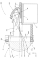
- FIG. 3 is a cross-sectional view taken along line III-III in FIG. 2
- FIG. 4 is a cross-sectional view taken along line IV-IV in FIG. 2.
- the first lamp unit 22A on the right side includes a projection lens 32A having an optical axis Ax extending in the front-to-rear direction of the lamp, a light source 34A arranged rearward of the rear focus F of the projection lens 32A (more precisely, the rear focus in the vertical cross section), a reflector 36A arranged to cover the light source 34A from above and reflect the light emitted from the light source 34A toward the projection lens 32A, and a shade 38A arranged between the reflector 36A and the projection lens 32A and blocking a portion of the reflected light from the reflector 36A.
- the projection lens 32A is a biconvex lens arranged with a tilt to the right relative to the front direction of the lamp, and is configured to project the light source image formed on the rear focal plane, which is a focal plane including the rear focal point F, as an inverted image onto a virtual vertical screen in front of the lamp.
- the front surface 32Aa of the projection lens 32A has a convex curved vertical cross-sectional shape and a convex curved horizontal cross-sectional shape tilted to the right
- the rear surface 32Ab of the projection lens 32A has a straight vertical cross-sectional shape and a convex curved horizontal cross-sectional shape tilted to the right.
- the light source 34A is a light-emitting element (specifically, a white light-emitting diode) and has a horizontally elongated rectangular light-emitting surface 34Aa.
- the light source 34A is arranged with the light-emitting surface 34Aa facing upward on the optical axis Ax.
- the reflector 36A is configured to direct the light emitted from the light source 34A as convergent light into the projection lens 32A.
- the reflective surface 36Aa of the reflector 36A is composed of a curved surface that is approximately ellipsoidal with the light emission center of the light source 34A as the first focus, and its eccentricity is set to gradually increase from the vertical cross section to the horizontal cross section.
- the reflector 36A converges the light emitted from the light source 34A to a point located on the front side of the lamp from the rear focal point F in the vertical cross section, and displaces the convergence position further forward of the lamp in the horizontal cross section.
- the reflective surface 36Aa of the reflector 36A is formed so that its right region extends to a position further forward of the lamp than the left region.
- the shade 38A has an upward reflecting surface 38Aa that reflects a portion of the reflected light from the reflector 36A upward toward the projection lens 32A.
- the left side area of this upward reflecting surface 38Aa located to the left of the optical axis Ax (right side when viewed from the front of the lamp), is composed of a horizontal plane including the optical axis Ax, and the right side area, located to the right of the optical axis Ax, is composed of a horizontal plane one step lower than the left side area via a short slope.
- the front edge 38Aa1 of this upward reflecting surface 38Aa extends from the rear focal point F to both the left and right sides in a curved manner toward the front side of the lamp.
- this upward reflecting surface 38Aa is formed with a substantially constant front-to-rear width, and is formed so that its rear edge is located further forward of the lamp than the front edge of the reflecting surface 36Aa of the reflector 36A.
- the first lamp unit 22B on the left side has a projection lens 32B, a light source 34A, a reflector 36A, and a shade 38B that are similar to the projection lens 32A, light source 34A, reflector 36A, and shade 38A of the first lamp unit 22A on the right side.
- the projection lens 32B has a shape symmetrical to the projection lens 32A
- the reflective surface 36Ba of the reflector 36B has a shape symmetrical to the reflective surface 36Aa of the reflector 36A.
- the second lamp unit 22C like the first lamp unit 22A, has a projection lens 32C, a light source 34C, and a reflector 36C, but does not have a shade 38A like the first lamp unit 22A.
- the reflective surface 36Ca of the reflector 36C in the second lamp unit 22C has a slightly different surface shape than the reflective surface 36Aa of the reflector 36A in the first lamp unit 22A, and neither of the left nor right areas extend to the front of the lamp.
- the projection lens 32C of the second lamp unit 22C is configured as a cylindrical lens extending in a horizontal direction perpendicular to the front-to-rear direction of the lamp.
- the projection lens 32C has a front surface 32Ca with a convex curved vertical cross section and a rear surface 32Cb with a straight vertical cross section.
- the projection lens 32C is formed so that both the left and right ends of the front surface 32Ca are smoothly connected to the front surfaces 32Aa, 32Ba of the projection lenses 32A, 32B of the first lamp unit 22A, 22B, and also so that both the left and right ends of the rear surface 32Cb are connected to the rear surfaces 32Ab, 32Bb of the projection lenses 32A, 32B.
- the projection lenses 32A, 32B, and 32C of the first lamp units 22A and 22B and the second lamp unit 22C of the lamp unit assembly 20 are formed from a single lens member 30.
- An outer peripheral flange portion 30a is formed around the entire circumference of the lens member 30.
- the light sources 34A, 22B, and 34C of the first lamp unit 22A, 22B and the second lamp unit 22C are supported on a common substrate 40 that is arranged to extend in the left-right direction along a horizontal plane. This substrate 40 is supported on the upper surface of a metal heat sink 50.
- the heat sink 50 has a main body 52 that extends in the left-right direction along a horizontal plane, and a number of heat dissipation fins 54 that are formed to extend downward at intervals in the left-right direction from the underside of the main body 52.
- the lens member 30 is supported by a resin lens holder 60.
- the lens holder 60 has a vertical frame portion 60b that extends along a vertical plane perpendicular to the front-to-rear direction of the lamp. This vertical frame portion 60b is formed in a horizontally elongated rectangular shape when the lamp is viewed from the front.
- the lens member 30 is fixed to the lens holder 60 with its outer peripheral flange portion 30a abutting against the vertical frame portion 60b of the lens holder 60 from the front side of the lamp.
- the lens holder 60 has a horizontal flange portion 60a that extends along a horizontal plane and surrounds the outer peripheral edges of the reflectors 36A, 36B, and 36C in the first lamp unit 22A, 22B and the second lamp unit 22C.
- the three reflectors 36A, 36B, and 36C are integrally formed with the lens holder 60.
- the shades 38A and 38B of the first lamp units 22A and 30B are also integrally formed with the lens holder 60.
- a light blocking member 62A is disposed between the first lamp unit 22A and the second lamp unit 22C on the right side, and a light blocking member 62B is disposed between the first lamp unit 22B and the second lamp unit 22C on the left side.
- Each of these pair of light blocking members 62A, 62B is configured as a plate-like member formed to extend in the front-to-rear direction of the lamp along a vertical plane.
- the light blocking member 62A is configured to prevent direct light from the light source 34A of the first lamp unit 22A from entering the projection lens 32C of the second lamp unit 22C at the first side surface portion 62Aa constituting the right side surface portion, and to prevent direct light from the light source 34C of the second lamp unit 22C from entering the projection lens 22A of the first lamp unit 22A at the second side surface portion 62Ac constituting the left side surface portion.
- the light blocking member 62B is configured to prevent direct light from the light source 34B of the first lamp unit 22B from entering the projection lens 32C of the second lamp unit 22C at the first side surface portion 62Bb constituting the left side surface portion, and to prevent direct light from the light source 34C of the second lamp unit 22C from entering the projection lens 22B of the first lamp unit 22B at the second side surface portion 62Bc constituting the right side surface portion.
- the pair of left and right light blocking members 62A, 62B are formed integrally with the lens holder 60.
- the front end of the light blocking member 62A is connected to the vertical frame portion 60b of the lens holder 60, and its rear end is connected to the boundary portion between the reflectors 36A and 36C of the first and second lamp units 22A and 22C.
- the front end of the light blocking member 62B is connected to the vertical frame portion 60b of the lens holder 60, and its rear end is connected to the boundary portion between the reflectors 36B and 36C of the first and second lamp units 22B and 22C.
- the optical axis Ax of each of the first lamp units 22A, 22B and the second lamp unit 22C is arranged to extend downward by approximately 0.5 to 0.6° toward the front of the lamp relative to the horizontal plane.
- FIG. 5 is a perspective view showing the low beam light distribution pattern PL-1 and the high beam light distribution pattern PH-1 formed by the light emitted from the vehicle lamp 10.
- the low beam light distribution pattern PL-1 is a low beam light distribution pattern with left light distribution, and cutoff lines CL1 and CL2 with left and right steps are formed at the upper end.
- These cutoff lines CL1 and CL2 extend horizontally with left and right steps, bounded by a V-V line that passes vertically through H-V, which is the vanishing point in front of the lamp, and the part to the right of the V-V line is formed as the oncoming vehicle lane side cutoff line CL1, and the part to the left of the V-V line is formed as the own vehicle lane side cutoff line CL2, which is stepped up from the oncoming vehicle lane side cutoff line CL1 via an inclined portion.
- elbow point E which is the intersection point between the oncoming lane cutoff line CL1 and the V-V line, is located approximately 0.5 to 0.6° below H-V. This is because the optical axis Ax of the first and second lamp units 22A, 30B extends approximately 0.5 to 0.6° downward from the horizontal plane toward the front of the lamp.
- the low beam light distribution pattern PL-1 is formed as a composite light distribution pattern of the low beam light distribution pattern PL-1A formed by the light emitted from the first lamp unit 22A on the right side and the low beam light distribution pattern PL-1B formed by the light emitted from the first lamp unit 22B on the left side.
- the low beam light distribution pattern PL-1A is formed by projecting the light source image of the light source 34A, which is formed on the rear focal plane of the projection lens 32A by the light from the light source 34A reflected by the reflector 36A, as an inverted projection image onto the virtual vertical screen by the projection lens 32A, and the cutoff lines CL1 and CL2 are formed as inverted projection images of the front edge 38a1 of the upward reflecting surface 38Aa of the shade 38A.
- the low beam light distribution pattern PL-1A is formed as a light distribution pattern in which the diffusion angle to the left is greater than the diffusion angle to the right. This is because the right area of the reflective surface 36Aa of the reflector 36A of the first lamp unit 22A is formed to extend further forward than the left area.
- the low beam light distribution pattern PL-1B is formed as a light distribution pattern in which the diffusion angle to the right is greater than the diffusion angle to the left. This is because the left region of the reflective surface 36Ba of the reflector 36B of the first lamp unit 22B is formed to extend further forward than the right region.
- the small striped light distribution pattern Sa indicated by the two-dot chain line is a light distribution pattern that would be formed if the light blocking member 62A were not formed, when direct light from the light source 34A of the first lamp unit 22A enters the projection lens 32C of the second lamp unit 22C and is emitted as stray light from this projection lens 32C. It is formed near the left end of the low beam light distribution pattern PL-1A.
- the small striped light distribution pattern Sb indicated by the two-dot chain line in FIG. 5(a) is a light distribution pattern that would be formed if the light blocking member 62B were not formed, when direct light from the light source 34B of the first lamp unit 22B enters the projection lens 32C of the second lamp unit 22C and is emitted as stray light from this projection lens 32C, and is formed near the right end of the low beam light distribution pattern PL-1B.
- the lighting unit assembly 20 of the vehicle lighting fixture 10 is equipped with light blocking members 62A and 62B, so these striped light distribution patterns Sa and Sb are not formed.
- the high beam light distribution pattern PH-1 is formed as a light distribution pattern in which an additional light distribution pattern PA-1 formed by the light emitted from the second lamp unit 22C is added to the low beam light distribution pattern PL-1.
- the additional light distribution pattern PA-1 is a horizontally elongated light distribution pattern centered on H-V, and is formed so as to straddle vertically the cutoff lines CL1 and CL2 of the low beam light distribution pattern PL-1.
- This additional light distribution pattern PA-1 is formed with a smaller left-right diffusion angle than the low beam light distribution pattern PL-1.
- the small striped light distribution pattern ScA indicated by the two-dot chain line in FIG. 5(b) is a light distribution pattern that would be formed if the light blocking member 62A were not formed, when direct light from the light source 34C of the second lamp unit 22C enters the projection lens 22A of the first lamp unit 22A and is emitted from this projection lens 22A as stray light.
- the small stripe-like light distribution pattern ScB indicated by the two-dot chain line in FIG. 5(b) is a light distribution pattern that would be formed if the light-shielding member 62B were not formed, as direct light from the light source 34B of the first lamp unit 22B would enter the projection lens 32C of the second lamp unit 22C, enter from this projection lens 32C into the projection lens 32B of the first lamp unit 22B, and exit from this projection lens 32B as stray light.
- the pair of left and right light distribution patterns ScA, ScB are formed at positions further outboard than the pair of left and right light distribution patterns Sa, Sb.
- the rear surface 32Cb of the projection lens 32C has a straight horizontal cross-sectional shape, while the rear surfaces 32Ab, 32Bb of the projection lenses 32A, 32B have convex curved horizontal cross-sectional shapes.
- the high beam light distribution pattern PH-1 will have streaky light unevenness at both the left and right ends due to the light distribution patterns Sa and Sb, as well as streaky light unevenness due to the light distribution patterns ScA and ScB, resulting in reduced visibility of the road ahead of the vehicle.
- the light blocking members 62A and 62B are formed on the lighting unit assembly 20 of the vehicle lighting fixture 10, so these striped light distribution patterns Sa, Sb, ScA, and ScB are not formed.
- the vehicle lamp 10 is configured with a first lamp unit 22A, 22B and a second lamp unit 22C, which have different light distribution functions, arranged side by side in the left-right direction.
- the first lamp units 22A, 22B are configured to emit light emitted from light sources 34A, 34B (first light source) toward the front of the lamp via projection lenses 32A, 32B (first projection lens)
- the second lamp unit 22C is configured to emit light emitted from light source 34C (second light source) toward the front of the lamp via projection lens 32C (second projection lens).
- the three projection lenses 32A, 32B, 30C are formed from a single lens member 30, the design of the vehicle lamp 10 can be improved and the number of parts can be reduced.
- first lamp unit 22A, 22B and the second lamp unit 22C there are arranged light-shielding members 62A, 62B having first side portions 62Aa, 62Bb that prevent direct light from the light source 34A, 34B from entering the projection lens 32C and second side portions 62Ac, 62Bc that prevent direct light from the light source 34C from entering the projection lens 32A, 32B.
- the vehicle lamp 10 is equipped with a lens holder 60 that supports the lens member 30, and the light blocking members 62A, 62B are formed integrally with the lens holder 60, so that the positional accuracy of the light blocking members 62A, 62B can be sufficiently ensured, thereby improving the light blocking function of the light blocking members 62A, 62B.
- the first lamp units 22A, 22B are lamp units for forming the low beam light distribution pattern PL-1, and the rear surfaces 32Ab, 32Bb of the projection lenses 32A, 32B have a convex curved horizontal cross-sectional shape, so that the following effects can be obtained.
- the vehicle lamp 10 is configured to include, as the first lamp unit 22A, 22B, reflectors 36A, 36B that reflect the light emitted from the light sources 34A, 34B toward the projection lenses 32A, 32B, and shades 38A, 38B that are disposed between the reflectors 6A, 36B and the projection lenses 32A, 32B and block a portion of the reflected light from the reflectors 6A, 36B.
- the second lamp unit 22C and The reflector 36C reflects the light emitted from the light source 34C toward the projection lens 32C, and these reflectors 36A, 36B, 36C and shades 38A, 38B are formed integrally with the lens holder 60, so that the light distribution control in each of the first lamp unit 22A, 22B and the second lamp unit 22C can be performed with high precision, and the number of parts in the vehicle lamp 10 can be further reduced.
- the pair of left and right light blocking members 62A, 62B are described as being formed integrally with the lens holder 60, but it is also possible to adopt a configuration in which these light blocking members 62A, 62B are fixed to the lens holder 60 by adhesion, engagement, etc.
- the lamp unit assembly 20 is described as having a pair of first lamp units 22A and 22B on the left and right, but it is also possible to adopt a configuration having a single first lamp unit or three or more first lamp units.
- FIG. 6 is a diagram similar to FIG. 1, showing a vehicle lamp 110 according to this modified example.
- the basic configuration of this modified example is the same as that of the above embodiment, but the configuration of the pair of left and right light blocking members 162A, 162B in the lamp unit assembly 120 is partially different from that of the above embodiment.
- first side portions 162Aa, 162Bb and the second side portions 162Ac, 162Bc of the pair of left and right light blocking members 162A, 162B are configured as light diffusing surfaces.
- a plurality of light diffusion elements 162As are formed in horizontal stripes on the first and second side portions 162Aa, 16Ac of the light blocking member 162A, and a plurality of light diffusion elements 162Bs are formed in horizontal stripes on the first and second side portions 162Ba, 16Bc of the light blocking member 162B.
- the light blocking member 162A prevents direct light from the light source 34A of the first lamp unit 22A from entering the projection lens 32C at its first side surface 162Aa, and reflects the direct light from this light source 34A as diffused light, while the light blocking member 162A prevents direct light from the light source 34C of the second lamp unit 22C from entering the projection lens 32A at its second side surface 162Ac, and reflects the direct light from this light source 34C as diffused light.
- the light blocking member 162B prevents direct light from the light source 34B of the first lamp unit 22B from entering the projection lens 32C at its first side surface 162Ba, and reflects the direct light from the light source 34B as diffused light, while the light blocking member 162B prevents direct light from the light source 34C of the second lamp unit 22C from entering the projection lens 32B at its second side surface 162Bc, and reflects the direct light from the light source 34C as diffused light.
- a plurality of light diffusion elements 162As are formed in horizontal stripes on the first and second side portions 162Aa, 162Ac of the light blocking member 162A, and a plurality of light diffusion elements 162Bs are formed in horizontal stripes on the first and second side portions 162Ba, 162Bc of the light blocking member 162B, but it is also possible to adopt a configuration in which a light diffusion treatment such as embossing or frosting has been applied.
- FIG. 7 is a view similar to FIG. 2, showing a lamp unit assembly 220 of a vehicle lamp according to this modified example. Note that the lamp unit assembly 220 shown in FIG. 7 is a lamp unit assembly of a vehicle lamp arranged at the right front end of the vehicle.
- the lamp unit assembly 220 of this modified example is configured with a first lamp unit 222A and a second lamp unit 222C, which have different light distribution functions, arranged side-by-side in the left-right direction, and the projection lenses 232A, 232C are composed of a single lens member 230, but the shape of the lens member is different from that of the above embodiment.
- the projection lens 232A of the first lamp unit 222A has a front surface 232Aa that has a convex curved vertical cross section and extends linearly in a direction that is inclined toward the rear of the lamp toward the outside in the vehicle width direction (i.e., the right side), and its rear surface 232Ab has a linear vertical cross section and a convex curved horizontal cross section that is inclined to the right.
- the projection lens 232C of the second lamp unit 222C has a front surface 232Ca formed in a convex curved shape, and a rear surface 232Cb formed as a vertical surface perpendicular to the front-to-rear direction of the lamp.
- the right end of the front surface 232Ca of this projection lens 232C is formed so as to smoothly connect with the front surface 232Aa of the projection lens 232A of the first lamp unit 222A, and the right end of the rear surface 232Cb is formed so as to connect with the rear surface 232Ab of the projection lens 232A.
- the configurations of the light source 234A, reflector 236A, and shade 238A of the first lamp unit 222A are substantially the same as those in the above embodiment, and the configurations of the light source 234C and reflector 236C of the second lamp unit 222C are also substantially the same as those in the above embodiment, but are positioned in a relatively displaced state toward the front of the lamp.
- the lamp unit assembly 220 of this modified example is configured such that the board 240A on which the light source 234A of the first lamp unit 222A is mounted and the board 240C on which the light source 234C of the second lamp unit 222C is mounted are each supported by the main body 252 of the heat sink 250.
- the lens member 230 is also supported by the lens holder 260.
- the lens holder 260 has a vertical frame portion 260b that is formed in a roughly U-shape when viewed from the front of the lamp, and the lens member 230 is positioned in this vertical frame portion 260b.
- the lens holder 260 has a horizontal flange portion 260a that extends along a horizontal plane and surrounds the outer peripheral edges of the reflectors 236A, 236C in the first and second lamp units 222A, 222C.
- the two reflectors 236A, 236C are integrally formed with the lens holder 260.
- the shade 238A of the first lamp unit 222A is also integrally formed with the lens holder 260.
- a light blocking member 262A is disposed between the first lamp unit 222A and the second lamp unit 222C.
- This light blocking member 262A is configured as a plate-shaped member formed to extend in the front-to-rear direction of the lamp along a vertical plane, and is formed integrally with the lens holder 260.
- the light blocking member 262A is configured to prevent direct light from the light source 234A of the first lamp unit 222A from entering the projection lens 232C of the second lamp unit 222C at the first side surface portion 262Aa constituting the right side surface portion, and to prevent direct light from the light source 234C of the second lamp unit 222C from entering the projection lens 232A of the first lamp unit 222A at the second side surface portion 262Ac constituting the left side surface portion.
- FIG. 8 is a perspective view showing the low beam light distribution pattern PL-2 and the high beam light distribution pattern PH-2 formed by the light emitted from the vehicle lamp according to this modified example.
- the low beam light distribution pattern PL-2 is a light distribution pattern formed by the light emitted from the first lamp unit 22A, and has approximately the same shape as the low beam light distribution pattern PL-1 formed in the above embodiment.
- the small striped light distribution pattern Sa-2 indicated by the two-dot chain line is a light distribution pattern that would be formed if the light blocking member 362 were not formed, when direct light from the light source 234A of the first lamp unit 222A enters the projection lens 232C of the second lamp unit 222C and is emitted as stray light from this projection lens 232C. It is formed near the left end of the low beam light distribution pattern PL-2.
- the lighting unit assembly 220 is equipped with a light blocking member 262A, so this type of streak-like light distribution pattern Sa-2 is not formed.
- the high beam light distribution pattern PH-2 is formed as a light distribution pattern in which an additional light distribution pattern PA-2 formed by the light emitted from the second lamp unit 222C is added to the low beam light distribution pattern PL-2.
- the additional light distribution pattern PA-2 has approximately the same shape as the additional light distribution pattern PA-1 formed in the above embodiment.
- the small striped light distribution pattern ScC indicated by the two-dot chain line in FIG. 8(b) is a light distribution pattern that would be formed if the light blocking member 262A were not formed, when direct light from the light source 234C of the second lamp unit 222C enters the projection lens 232A of the first lamp unit 222A and is emitted from this projection lens 232A as stray light.
- the light distribution pattern Sc-2 is formed at a position further outward from the right end of the high beam light distribution pattern PH-2. This is because the rear surface 232A of the projection lens 232A has a convex curved horizontal cross-sectional shape, and direct light from the light source 234C is incident on the left end of the rear surface 232A.
- the light blocking member 262A is formed in the lamp unit assembly 220, so this type of streak-like light distribution pattern Sc-2 is not formed.
- the projection lens 232A of the first lamp unit 222A is inclined toward the rear of the lamp and outward in the vehicle width direction, which makes it easy for streaky light unevenness to occur in positions away from the high beam light distribution pattern PH-2. Therefore, it is particularly effective to use the light blocking member 262A of the lamp unit assembly 220 to prevent streaky light unevenness from occurring.
- the second lamp unit 222B is described as a lamp unit for forming an additional light distribution pattern PA-2 of the high beam light distribution pattern PH-2.
- an adaptive driving beam lamp unit configured to form multiple small light distribution patterns in parallel at a position overlapping with the cutoff lines CL1 and CL2 of the low beam light distribution pattern PL-2.
- the present invention is not limited to the configurations described in the above embodiment and its modified examples, and various other modified configurations can be adopted.
- Lamp body 14 Light-transmitting cover 20, 120, 220 Lamp unit assembly 22A, 22B, 222A First lamp unit 22C, 222C Second lamp unit 30, 230 Lens member 30a Outer periphery flange portion 32A, 32B, 232A Projection lens (first projection lens) 32Aa, 32Ba, 32Ca, 232Aa, 232Ca front surface 32Ab, 32Bb, 32Cb, 232Ab, 232Cb rear surface 32C, 232C projection lens (second projection lens) 34A, 34B, 234A light source (first light source) 34Aa: Light emitting surface 34C, 234C: Light source (second light source) 36A, 36B, 236A Reflector (first reflector) 36Aa, 36Ba, 36Ca: Reflecting surfaces 36C, 236C: Reflector (second reflector) 38A, 38B, 238A Shade 38Aa Upward reflecting surface 38Aa1 Front edge 40, 240A,
Landscapes
- Engineering & Computer Science (AREA)
- General Engineering & Computer Science (AREA)
- Non-Portable Lighting Devices Or Systems Thereof (AREA)
Abstract
配光機能が異なる第1および第2灯具ユニットが左右方向に並んだ状態で配置された車両用灯具において、第1および第2灯具ユニットの投影レンズが単一のレンズ部材で構成されている場合であっても、グレア光が発生したり灯具前方路面に光スジ等の配光ムラが発生してしまうのを未然に防止する。第1灯具ユニット22Aの投影レンズ32Aと第2灯具ユニット22Cの投影レンズ30Cとを単一のレンズ部材30で構成した上で、両者間に、第1灯具ユニット22Aの光源34Aからの直射光が投影レンズ32Cに入射するのを阻止する第1側面部62Aaおよび第2灯具ユニット22Cの光源34Cからの直射光が投影レンズ32Aに入射するのを阻止する第2側面部62Acを有する遮光部材38Aが配置された構成とする。これにより、グレア光が発生したり灯具前方路面に光スジ等の配光ムラが発生してしまうのを未然に防止する。
Description
本願発明は、配光機能が異なる第1および第2灯具ユニットが左右方向に並んだ状態で配置された車両用灯具に関するものである。
従来より、車両用灯具の構成として、配光機能が異なる第1および第2灯具ユニットが左右方向に並んだ状態で配置されたものが知られている。
また、これら第1および第2灯具ユニットの各々の構成として、光源からの出射光を投影レンズを介して灯具前方へ向けて出射させるように構成されたものも知られている。
「特許文献1」には、このような車両用灯具の構成として、第1および第2灯具ユニットの投影レンズが単一のレンズ部材で構成されたものが記載されている。
上記「特許文献1」に記載された車両用灯具のように第1および第2灯具ユニットの投影レンズを単一のレンズ部材で構成することにより、車両用灯具の意匠性を高めることが可能となり、また、部品点数の削減を図ることも可能となる。
しかしながら、このような構成を採用した場合には、配光機能が異なる第1および第2灯具ユニットのうち一方の灯具ユニットの光源からの直射光の一部が他方の灯具ユニットの投影レンズに入射してしまうこととなる。そして、このように配光機能が異なる灯具ユニットの投影レンズに対して光入射が行われてしまうと、グレア光が発生したり灯具前方路面に光スジ等の配光ムラが発生しやすくなってしまう。
本願発明は、このような事情に鑑みてなされたものであって、配光機能が異なる第1および第2灯具ユニットが左右方向に並んだ状態で配置された車両用灯具において、第1および第2灯具ユニットの投影レンズが単一のレンズ部材で構成されている場合であっても、グレア光が発生したり灯具前方路面に光スジ等の配光ムラが発生してしまうのを未然に防止することができる車両用灯具を提供することを目的とするものである。
本願発明は、第1灯具ユニットと第2灯具ユニットとの間に所定の遮光部材が配置された構成とすることにより、上記目的達成を図るようにしたものである。
すなわち、本願発明に係る車両用灯具は、
配光機能が異なる第1および第2灯具ユニットが左右方向に並んだ状態で配置された車両用灯具において、
上記第1灯具ユニットは、第1光源からの出射光を第1投影レンズを介して灯具前方へ向けて出射させるように構成されており、
上記第2灯具ユニットは、第2光源からの出射光を第2投影レンズを介して灯具前方へ向けて出射させるように構成されており、
上記第1投影レンズと上記第2投影レンズとが単一のレンズ部材で構成されており、
上記第1灯具ユニットと上記第2灯具ユニットとの間に、上記第1光源からの直射光が上記第2投影レンズに入射するのを阻止する第1側面部および上記第2光源からの直射光が上記第1投影レンズに入射するのを阻止する第2側面部を有する遮光部材が配置されている、ことを特徴とするものである。
配光機能が異なる第1および第2灯具ユニットが左右方向に並んだ状態で配置された車両用灯具において、
上記第1灯具ユニットは、第1光源からの出射光を第1投影レンズを介して灯具前方へ向けて出射させるように構成されており、
上記第2灯具ユニットは、第2光源からの出射光を第2投影レンズを介して灯具前方へ向けて出射させるように構成されており、
上記第1投影レンズと上記第2投影レンズとが単一のレンズ部材で構成されており、
上記第1灯具ユニットと上記第2灯具ユニットとの間に、上記第1光源からの直射光が上記第2投影レンズに入射するのを阻止する第1側面部および上記第2光源からの直射光が上記第1投影レンズに入射するのを阻止する第2側面部を有する遮光部材が配置されている、ことを特徴とするものである。
上記「車両用灯具」は、配光機能が異なる第1および第2灯具ユニットが左右方向に並んだ状態で配置されていれば、第1および第2灯具ユニットの各々の具体的な配光機能やその配置個数については特に限定されるものではない。
上記「遮光部材」は、第1光源からの直射光が第2投影レンズに入射するのを阻止する第1側面部および第2光源からの直射光が第1投影レンズに入射するのを阻止する第2側面部を有していれば、その具体的な構成については特に限定されるものではない。
本願発明に係る車両用灯具は、配光機能が異なる第1および第2灯具ユニットが左右方向に並んだ状態で配置された構成となっており、第1灯具ユニットとして第1光源からの出射光を第1投影レンズを介して灯具前方へ向けて出射させるように構成されるとともに第2灯具ユニットとして第2光源からの出射光を第2投影レンズを介して灯具前方へ向けて出射させるように構成されているが、第1投影レンズと第2投影レンズとが単一のレンズ部材で構成されているので、車両用灯具の意匠性を高めることができるとともに部品点数の削減を図ることができる。
その上で、第1灯具ユニットと第2灯具ユニットとの間には、第1光源からの直射光が第2投影レンズに入射するのを阻止する第1側面部および第2光源からの直射光が第1投影レンズに入射するのを阻止する第2側面部を有する遮光部材が配置されているので、配光機能が異なる灯具ユニットの投影レンズに対して光入射が行われることによってグレア光が発生したり灯具前方路面に光スジ等の配光ムラが発生してしまうのを未然に防止することができる。
このように本願発明によれば、配光機能が異なる第1および第2灯具ユニットが左右方向に並んだ状態で配置された車両用灯具において、第1および第2灯具ユニットの投影レンズが単一のレンズ部材で構成されている場合であっても、グレア光が発生したり灯具前方路面に光スジ等の配光ムラが発生してしまうのを未然に防止することができる。
上記構成において、さらに、遮光部材としてその第1および第2側面部が光拡散面として構成されたものとすれば、遮光部材の第1側面部で反射した第1光源からの直射光が第1投影レンズに入射してしまうのを効果的に抑制することができ、また、遮光部材の第2側面部で反射した第2光源からの直射光が第2投影レンズに入射してしまうのを効果的に抑制することができる。そしてこれにより、遮光部材を配置したことによって第1および第2灯具ユニットの各々からの照射光によって形成される配光パターンに悪影響が及んでしまうのを効果的に抑制することができる。
上記「光拡散面」は、第1側面部に到達した第1光源からの直射光および第2側面部に到達した第2光源からの直射光を拡散反射させることが可能なものであれば、特定の表面形状に限定されるものではなく、例えば、シボ加工やフロスト加工等の光拡散処理が施された表面形状や複数の光拡散素子が縞状に形成された表面形状等が採用可能である。
上記構成において、さらに、第1および第2投影レンズを支持するレンズホルダを備えた構成とした上で、遮光部材がこのレンズホルダと一体的に形成された構成とすれば、遮光部材の位置精度を十分に確保することができ、これにより遮光部材の遮光機能を高めることができる。
上記構成において、さらに、第1灯具ユニットがロービーム用配光パターンを形成するための灯具ユニットであって、その第1投影レンズの後面が凸曲線状の水平断面形状を有している場合には、次のような作用効果を得ることができる。
すなわち、第1投影レンズとして、その後面が凸曲線状の水平断面形状を有する構成とすることにより、第1光源からの出射光に対する第1投影レンズの偏向制御を精度良く行うことが可能となる。一方、このような構成を採用した場合には、第2光源からの直射光の一部が第1投影レンズに入射することによって、第2灯具ユニットからの照射光により形成される配光パターンにおいて灯具前方路面に光スジ等の配光ムラを発生させやすくなってしまうので、本願発明の構成を採用することが特に効果的である。
上記構成において、さらに、第1灯具ユニットとして、第1光源からの出射光を第1投影レンズへ向けて反射させる第1リフレクタと、この第1リフレクタと第1投影レンズとの間に配置された状態で第1リフレクタからの反射光の一部を遮光するシェードとを備えた構成とするとともに、第2灯具ユニットとして、第2光源からの出射光を第2投影レンズへ向けて反射させる第2リフレクタを備えた構成とした上で、これら第1および第2リフレクタならびにシェードがレンズホルダと一体的に形成された構成とすれば、第1および第2灯具ユニットの各々における配光制御を精度良く行くことができ、かつ、車両用灯具の部品点数のさらなる削減を図ることができる。
以下、図面を用いて、本願発明の実施の形態について説明する。
図1は、本願発明の一実施形態に係る車両用灯具10を示す正面図である。また、図2は、車両用灯具10の灯具ユニットアッシー20を示す平面図である。
図1、2において、Xで示す方向が「灯具前方」であり、Yで示す方向が「灯具前方」と直交する「左方向」(灯具正面視では「右方向」)であり、Zで示す方向が「上方向」である。図1、2以外の図においても同様である。
図1、2に示すように、本実施形態に係る車両用灯具10は、ランプボディ12とその前端開口部に取り付けられた素通し状の透光カバー14とで形成される灯室内に、灯具ユニットアッシー20が収容された構成となっている。この灯具ユニットアッシー20は、左右1対の第1灯具ユニット22A、22Bと第2灯具ユニット22Cとが一体的に形成された構成となっている。
第1灯具ユニット22A、22Bおよび第2灯具ユニット22Cは、いずれもプロジェクタ型の灯具ユニットとして構成されており、左右方向(すなわち車幅方向)に並んだ状態で配置されている。その際、第1灯具ユニット22Aは第2灯具ユニット22Cの右側に位置しており、第1灯具ユニット22Bは第2灯具ユニット22Cの左側に位置している。
そして車両用灯具10は、左右1対の第1灯具ユニット22A、22Bからの照射光によってロービーム用配光パターンを形成するとともに、第2灯具ユニット22Cからの照射光を追加することによってハイビーム用配光パターンを形成するようになっている(これについては後述する)。
次に、第1灯具ユニット22A、22Bおよび第2灯具ユニット22Cの各々の具体的な構成について説明する。
図3は、図2のIII-III線断面図であり、図4は、図2のIV-IV線断面図である。
図3にも示すように、右側の第1灯具ユニット22Aは、灯具前後方向に延びる光軸Axを有する投影レンズ32Aと、この投影レンズ32Aの後側焦点(正確には鉛直断面内における後側焦点)Fよりも灯具後方側に配置された光源34Aと、この光源34Aを上方側から覆うように配置された状態で、光源34Aからの出射光を投影レンズ32Aへ向けて反射させるリフレクタ36Aと、このリフレクタ36Aと投影レンズ32Aとの間に配置された状態で、リフレクタ36Aからの反射光の一部を遮光するシェード38Aとを備えている。
投影レンズ32Aは、灯具正面方向に対して右側に傾斜した状態で配置された両凸レンズであって、その後側焦点Fを含む焦点面である後側焦点面上に形成される光源像を、反転像として灯具前方の仮想鉛直スクリーン上に投影するように構成されている。具体的には、投影レンズ32Aの前面32Aaは、凸曲線状の鉛直断面形状を有するとともに右側に傾斜した凸曲線状の水平断面形状を有しており、また、投影レンズ32Aの後面32Abは、直線状の鉛直断面形状を有するとともに右側に傾斜した凸曲線状の水平断面形状を有している。
光源34Aは、発光素子(具体的には白色発光ダイオード)であって、横長矩形状の発光面34Aaを有している。そして、この光源34Aは、その発光面34Aaを光軸Ax上において上向きにした状態で配置されている。
リフレクタ36Aは、光源34Aからの出射光を収束光として投影レンズ32Aに入射させるように構成されている。
具体的には、リフレクタ36Aの反射面36Aaは、光源34Aの発光中心を第1焦点とする略楕円面状の曲面で構成されており、その離心率が鉛直断面から水平断面へ向けて徐々に大きくなるように設定されている。そしてこれにより、リフレクタ36Aは、光源34Aからの出射光を鉛直断面内においては後側焦点Fの灯具前方側に位置する点に収束させるとともに水平断面内においてはその収束位置をさらに灯具前方側へ変位させるようになっている。リフレクタ36Aの反射面36Aaは、その右側領域が左側領域よりも灯具前方の位置まで延びるように形成されている。
シェード38Aは、リフレクタ36Aからの反射光の一部を投影レンズ32Aへ向けて上向きに反射させる上向き反射面38Aaを有している。この上向き反射面38Aaは、光軸Axよりも左側(灯具正面視では右側)に位置する左側領域が光軸Axを含む水平面で構成されており、光軸Axよりも右側に位置する右側領域が、短い斜面を介して左側領域よりも一段低い水平面で構成されている。この上向き反射面38Aaの前端縁38Aa1は、後側焦点Fから左右両側へ向けて灯具前方側へ湾曲するようにして延びている。また、この上向き反射面38Aaは略一定の前後幅で形成されており、その後端縁がリフレクタ36Aの反射面36Aaの前端縁よりも灯具前方側に位置するように形成されている。
図1、2に示すように、左側の第1灯具ユニット22Bは、右側の第1灯具ユニット22Aの投影レンズ32A、光源34A、リフレクタ36Aおよびシェード38Aと同様の投影レンズ32B、光源34B、リフレクタ36Bおよびシェード38Bとを備えている。
ただし、第1灯具ユニット22Bは、その投影レンズ32Bが投影レンズ32Aに対して左右対称の形状を有しており、また、そのリフレクタ36Bの反射面36Baがリフレクタ36Aの反射面36Aaに対して左右対称の形状を有している。
図1、2、4に示すように、第2灯具ユニット22Cは、第1灯具ユニット22Aと同様、投影レンズ32Cと光源34Cとリフレクタ36Cとを備えているが、第1灯具ユニット22Aのようなシェード38Aは備えていない。
また、第2灯具ユニット22Cにおけるリフレクタ36Cの反射面36Caは、第1灯具ユニット22Aにおけるリフレクタ36Aの反射面36Aaとはその表面形状が多少異なっており、また、その左右いずれの領域も灯具前方まで延長形成されてはいない。
さらに、第2灯具ユニット22Cの投影レンズ32Cは、灯具前後方向と直交する水平方向に延びるシリンドリカルレンズとして構成されている。具体的には、投影レンズ32Cは、その前面32Caが凸曲線状の鉛直断面形状を有するとともにその後面32Cbが直線状の鉛直断面形状を有している。そして、この投影レンズ32Cは、その前面32Caの左右両端部において、第1灯具ユニット22A、22Bの投影レンズ32A、32Bの前面32Aa、32Baと滑らかに繋がるように形成されており、また、その後面32Cbの左右両端部において、投影レンズ32A、32Bの後面32Ab、32Bbと繋がるように形成されている。
すなわち、灯具ユニットアッシー20は、その第1灯具ユニット22A、22Bおよび第2灯具ユニット22Cの投影レンズ32A、32B、32Cが単一のレンズ部材30で構成されている。このレンズ部材30には、その全周にわたって外周フランジ部30aが形成されている。
第1灯具ユニット22A、22Bおよび第2灯具ユニット22Cの光源34A、22B、34Cは、水平面に沿って左右方向に延びるように配置された共通の基板40に支持されている。この基板40は、金属製のヒートシンク50の上面に支持されている。
ヒートシンク50は、水平面に沿って左右方向に延びる本体部52と、この本体部52の下面から左右方向に間隔をおいて下方へ延びるように形成された複数の放熱フィン54とを備えている。
レンズ部材30は、樹脂製のレンズホルダ60に支持されている。
レンズホルダ60は、灯具前後方向と直交する鉛直面に沿って延びる鉛直フレーム部60bを備えている。この鉛直フレーム部60bは、灯具正面視において横長矩形状に形成されている。そして、レンズ部材30は、その外周フランジ部30aをレンズホルダ60の鉛直フレーム部60bに灯具前方側から当接させた状態でレンズホルダ60に固定されている。
レンズホルダ60は、第1灯具ユニット22A、22Bおよび第2灯具ユニット22Cにおけるリフレクタ36A、36B、36Cの外周縁部を囲むようにして水平面に沿って延びる水平フランジ部60aを備えている。
3つのリフレクタ36A、36B、36Cは、レンズホルダ60と一体的に形成されている。また、第1灯具ユニット22A、30Bのシェード38A、38Bも、レンズホルダ60と一体的に形成されている。
図1、2に示すように、右側の第1灯具ユニット22Aと第2灯具ユニット22Cとの間には遮光部材62Aが配置されており、左側の第1灯具ユニット22Bと第2灯具ユニット22Cとの間には遮光部材62Bが配置されている。これら左右1対の遮光部材62A、62Bは、いずれも鉛直面に沿って灯具前後方向に延びるように形成された板状部材として構成されている。
遮光部材62Aは、その右側面部を構成する第1側面部62Aaにおいて第1灯具ユニット22Aの光源34Aからの直射光が第2灯具ユニット22Cの投影レンズ32Cに入射するのを阻止するとともに、その左側面部を構成する第2側面部62Acにおいて第2灯具ユニット22Cの光源34Cからの直射光が第1灯具ユニット22Aの投影レンズ22Aに入射するのを阻止するように構成されている。
同様に、遮光部材62Bは、その左側面部を構成する第1側面部62Bbにおいて第1灯具ユニット22Bの光源34Bからの直射光が第2灯具ユニット22Cの投影レンズ32Cに入射するのを阻止するとともに、その右側面部を構成する第2側面部62Bcにおいて第2灯具ユニット22Cの光源34Cからの直射光が第1灯具ユニット22Bの投影レンズ22Bに入射するのを阻止するように構成されている。
左右1対の遮光部材62A、62Bは、レンズホルダ60と一体的に形成されている。
具体的には、遮光部材62Aは、その前端部がレンズホルダ60の鉛直フレーム部60bに連結されるとともに、その後端部が第1および第2灯具ユニット22A、22Cのリフレクタ36A、36Cの境界部に連結されている。また、遮光部材62Bは、その前端部がレンズホルダ60の鉛直フレーム部60bに連結されるとともに、その後端部が第1および第2灯具ユニット22B、22Cのリフレクタ36B、36Cの境界部に連結されている。
灯具ユニットアッシー20は、車両用灯具10に組み込まれた状態では、第1灯具ユニット22A、22Bおよび第2灯具ユニット22Cの各々の光軸Axが水平面に対して灯具前方へ向けて0.5~0.6°程度下向きの方向に延びた状態で配置されるようになっている。
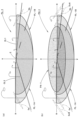
図5は、車両用灯具10からの照射光によって形成されるロービーム用配光パターンPL-1およびハイビーム用配光パターンPH-1を透視的に示す図である。
図5(a)に示すように、ロービーム用配光パターンPL-1は、左配光のロービーム用配光パターンであって、その上端部には左右段違いのカットオフラインCL1、CL2が形成されている。このカットオフラインCL1、CL2は、灯具正面方向の消点であるH-Vを鉛直方向に通るV-V線を境にして左右段違いで水平方向に延びており、V-V線よりも右側の部分が対向車線側カットオフラインCL1として形成されるとともに、V-V線よりも左側の部分が、対向車線側カットオフラインCL1から傾斜部を介して段上がりになった自車線側カットオフラインCL2として形成されている。
ロービーム用配光パターンPL-1において、対向車線側カットオフラインCL1とV-V線との交点であるエルボ点Eは、H-Vの0.5~0.6°程度下方に位置している。これは、第1および第2灯具ユニット22A、30Bの光軸Axが水平面に対して灯具前方へ向けて0.5~0.6°程度下向きの方向に延びていることによるものである。
ロービーム用配光パターンPL-1は、右側の第1灯具ユニット22Aからの照射光によって形成されるロービーム用配光パターンPL-1Aと、左側の第1灯具ユニット22Bからの照射光によって形成されるロービーム用配光パターンPL-1Bとの合成配光パターンとして形成されている。
ロービーム用配光パターンPL-1Aは、リフレクタ36Aで反射した光源34Aからの光によって投影レンズ32Aの後側焦点面上に形成された光源34Aの光源像を、投影レンズ32Aにより上記仮想鉛直スクリーン上に反転投影像として投影することにより形成され、そのカットオフラインCL1、CL2は、シェード38Aにおける上向き反射面38Aaの前端縁38a1の反転投影像として形成されるようになっている。
ロービーム用配光パターンPL-1Aは、左方向への拡散角が右方向への拡散角よりも大きい配光パターンとして形成されている。これは、第1灯具ユニット22Aのリフレクタ36Aにおける反射面36Aaの右側領域が左側領域よりも灯具前方まで延びるように形成されていることによるものである。
同様に、ロービーム用配光パターンPL-1Bは、右方向への拡散角が左方向への拡散角よりも大きい配光パターンとして形成されている。これは、第1灯具ユニット22Bのリフレクタ36Bにおける反射面36Baの左側領域が右側領域よりも灯具前方まで延びるように形成されていることによるものである。
図5(a)において、2点鎖線で示すスジ状の小さい配光パターンSaは、仮に遮光部材62Aが形成されていなかったとした場合に、第1灯具ユニット22Aの光源34Aからの直射光が第2灯具ユニット22Cの投影レンズ32Cに入射してこの投影レンズ32Cから迷光として出射することによって形成される配光パターンであって、ロービーム用配光パターンPL-1Aの左端部近傍に形成される。
また、図5(a)において2点鎖線で示すスジ状の小さい配光パターンSbは、仮に遮光部材62Bが形成されていなかったとした場合に、第1灯具ユニット22Bの光源34Bからの直射光が第2灯具ユニット22Cの投影レンズ32Cに入射してこの投影レンズ32Cから迷光として出射することによって形成される配光パターンであって、ロービーム用配光パターンPL-1Bの右端部近傍に形成される。
このような配光パターンSa、Sbが形成されてしまうと、ロービーム用配光パターンPL-1には、その左右両端部にスジ状の光ムラが発生してしまうので、車両前方走行路の視認性が低下してしまい、グレア光も発生してしまうこととなる。
実際には、車両用灯具10の灯具ユニットアッシー20は遮光部材62A、62Bを備えているので、このようなスジ状の配光パターンSa、Sbが形成されてしまうことはない。
図5(b)に示すように、ハイビーム用配光パターンPH-1は、ロービーム用配光パターンPL-1に対して、第2灯具ユニット22Cからの照射光によって形成される付加配光パターンPA-1が付加された配光パターンとして形成されている。
付加配光パターンPA-1は、H-Vを中心とする横長の配光パターンであって、ロービーム用配光パターンPL-1のカットオフラインCL1、CL2を上下に跨ぐようにして形成されている。この付加配光パターンPA-1は、ロービーム用配光パターンPL-1よりも小さい左右拡散角で形成されるようになっている。
図5(b)において2点鎖線で示す小さいスジ状の配光パターンScAは、仮に遮光部材62Aが形成されていなかったとした場合に、第2灯具ユニット22Cの光源34Cからの直射光が第1灯具ユニット22Aの投影レンズ22Aに入射してこの投影レンズ22Aから迷光として出射することによって形成される配光パターンである。
また、図5(b)において2点鎖線で示す小さいスジ状の配光パターンScBは、仮に遮光部材62Bが形成されていなかったとした場合に、第1灯具ユニット22Bの光源34Bからの直射光が第2灯具ユニット22Cの投影レンズ32Cに入射してこの投影レンズ32Cから第1灯具ユニット22Bの投影レンズ32Bに入射してこの投影レンズ32Bから迷光として出射することによって形成される配光パターンである。
その際、左右1対の配光パターンScA、ScBは、左右1対の配光パターンSa、Sbよりもさらに外側の位置に形成される。これは、投影レンズ32Cの後面32Cbが直線状の水平断面形状を有しているのに対して、投影レンズ32A、32Bの後面32Ab、32Bbが凸曲線状の水平断面形状を有していることによるものである。
このような配光パターンScA、ScBが形成されてしまうと、ハイビーム用配光パターンPH-1には、その左右両端部に配光パターンSa、Sbによるスジ状の光ムラと共に配光パターンScA、ScBによるスジ状の光ムラが発生してしまうので、車両前方走行路の視認性が低下してしまうこととなる。
実際には、車両用灯具10の灯具ユニットアッシー20には遮光部材62A、62Bが形成されているので、このようなスジ状の配光パターンSa、Sb、ScA、ScBが形成されてしまうことはない。
次に本実施形態の作用効果について説明する。
本実施形態に係る車両用灯具10は、配光機能が異なる第1灯具ユニット22A、22Bと第2灯具ユニット22Cとが左右方向に並んだ状態で配置された構成となっており、その際、第1灯具ユニット22A、22Bは光源34A、34B(第1光源)からの出射光を投影レンズ32A、32B(第1投影レンズ)を介して灯具前方へ向けて出射させるように構成されており、第2灯具ユニット22Cは光源34C(第2光源)からの出射光を投影レンズ32C(第2投影レンズ)を介して灯具前方へ向けて出射させる構成となっているが、3つの投影レンズ32A、32B、30Cは単一のレンズ部材30で構成されているので、車両用灯具10の意匠性を高めることができるとともに部品点数の削減を図ることができる。
その上で、第1灯具ユニット22A、22Bと第2灯具ユニット22Cとの間には、光源34A、34Bからの直射光が投影レンズ32Cに入射するのを阻止する第1側面部62Aa、62Bbと光源34Cからの直射光が投影レンズ32A、32Bに入射するのを阻止する第2側面部62Ac、62Bcを有する遮光部材62A、62Bとが配置されているので、配光機能が異なる第1灯具ユニット22A、22Bの投影レンズ32A、32Bと第2灯具ユニット22Cの投影レンズ32Cに対して光入射が行われることによってグレア光が発生したり灯具前方路面に光スジ等の配光ムラが発生してしまうのを未然に防止することができる。
このように本実施形態によれば、配光機能が異なる第1灯具ユニット22A、22Bと第2灯具ユニット22Cとが左右方向に並んだ状態で配置された車両用灯具10において、第1灯具ユニット22A、22Bの投影レンズ32A、32Bならびに第2灯具ユニット22Cの投影レンズ32Cが単一のレンズ部材30で構成されているにもかかわらず、灯具前方路面に光スジ等の配光ムラが発生してしまったり、グレア光が発生してしまうのを未然に防止することができる。
しかも、本実施形態に係る車両用灯具10は、レンズ部材30を支持するレンズホルダ60を備えており、かつ、遮光部材62A、62Bがレンズホルダ60と一体的に形成されているので、遮光部材62A、62Bの位置精度を十分に確保することができ、これにより遮光部材62A、62Bの遮光機能を高めることができる。
また、本実施形態に係る車両用灯具10は、第1灯具ユニット22A、22Bがロービーム用配光パターンPL-1を形成するための灯具ユニットであって、その投影レンズ32A、32Bの後面32Ab、32Bbが凸曲線状の水平断面形状を有しているので、次のような作用効果を得ることができる。
すなわち、投影レンズ32A、32Bとして、その後面32Ab、32Bbが凸曲線状の水平断面形状を有する構成とすることにより、光源34A、34Bからの出射光に対する32A、32B投影レンズの偏向制御を精度良く行うことが可能となる。一方、このような構成を採用した場合には、光源34Cからの直射光の一部が投影レンズ32A、32Bに入射することによって、第2灯具ユニット22Cからの照射光により形成される付加配光パターン配光パターンPA-1において灯具前方路面に光スジ等の配光ムラが発生しやすくなってしまうので、本実施形態の構成を採用することが特に効果的である。
さらに、本実施形態に係る車両用灯具10は、第1灯具ユニット22A、22Bとして、光源34A、34Bからの出射光を投影レンズ32A、32Bへ向けて反射させるリフレクタ36A、36Bと、これらリフレクタ6A、36Bと投影レンズ32A、32Bとの間に配置された状態でリフレクタ6A、36Bからの反射光の一部を遮光するシェード38A、38Bとを備えた構成となっており、また、第2灯具ユニット22Cとして、光源34Cからの出射光を投影レンズ32Cへ向けて反射させるリフレクタ36Cを備えた構成となっているが、これらリフレクタ36A、36B、36Cおよびシェード38A、38Bはレンズホルダ60と一体的に形成されているので、第1灯具ユニット22A、22Bおよび第2灯具ユニット22Cの各々における配光制御を精度良く行くことができ、かつ、車両用灯具10の部品点数のさらなる削減を図ることができる。
上記実施形態においては、左右1対の遮光部材62A、62Bがレンズホルダ60と一体的に形成されているものとして説明したが、これら遮光部材62A、62Bがレンズホルダ60に対して、接着や係合等によって固定された構成を採用することも可能である。
上記実施形態においては、灯具ユニットアッシー20として、左右1対の第1灯具ユニット22A、22Bを備えているものとして説明したが、単一または3つ以上の第1灯具ユニットを備えた構成を採用することも可能である。
次に、上記実施形態の変形例について説明する。
まず、上記実施形態の第1変形例について説明する。
図6は、本変形例に係る車両用灯具110を示す、図1と同様の図である。
図6に示すように、本変形例の基本的な構成は上記実施形態の場合と同様であるが、灯具ユニットアッシー120における左右1対の遮光部材162A、162Bの構成が上記実施形態の場合と一部異なっている。
すなわち本変形例においては、左右1対の遮光部材162A、162Bの第1側面部162Aa、162Bbおよび第2側面部162Ac、162Bcが光拡散面として構成されている。
具体的には、遮光部材162Aの第1および第2側面部162Aa、16Acには複数の光拡散素子162Asが横縞状に形成されており、また、遮光部材162Bの第1および第2側面部162Ba、16Bcには複数の光拡散素子162Bsが横縞状に形成されている。
これにより、遮光部材162Aは、その第1側面部162Aaにおいて第1灯具ユニット22Aの光源34Aからの直射光が投影レンズ32Cに入射するのを阻止した上で、この光源34Aからの直射光を拡散光として反射させるとともに、その第2側面部162Acにおいて第2灯具ユニット22Cの光源34Cからの直射光が投影レンズ32Aに入射するのを阻止した上で、この光源34Cからの直射光を拡散光として反射させるようになっている。
また、遮光部材162Bは、その第1側面部162Baにおいて第1灯具ユニット22Bの光源34Bからの直射光が投影レンズ32Cに入射するのを阻止した上で、この光源34Bからの直射光を拡散光として反射させるとともに、その第2側面部162Bcにおいて第2灯具ユニット22Cの光源34Cからの直射光が投影レンズ32Bに入射するのを阻止した上で、この光源34Cからの直射光を拡散光として反射させるようになっている。
本変形例の構成を採用することにより、遮光部材162A、162Bの第1側面部162Aa、162Bbで反射した光源34A、34Bからの直射光が投影レンズ32A、32Bに入射してしまうのを効果的に抑制することができ、また、遮光部材162A、162Bの第2側面部162Ac、162Bcで反射した光源34Cからの直射光が投影レンズ32Cに入射してしまうのを効果的に抑制することができる。
そしてこれにより、遮光部材162A、162Bを配置したことによってロービーム用配光パターンおよびハイビーム用配光パターンに不用意に配光ムラが発生してしまうといった悪影響が及んでしまうのを効果的に抑制することができる。
上記第1変形例においては、遮光部材162Aの第1および第2側面部162Aa、162Acに複数の光拡散素子162Asが横縞状に形成されるとともに遮光部材162Bの第1および第2側面部162Ba、162Bcに複数の光拡散素子162Bsが横縞状に形成されているものとして説明したが、これ以外にもシボ加工やフロスト加工等の光拡散処理が施された構成を採用することも可能である。
次に、上記実施形態の第2変形例について説明する。
図7は、本変形例に係る車両用灯具の灯具ユニットアッシー220を示す、図2と同様の図である。なお、図7に示す灯具ユニットアッシー220は、車両の右前端部に配置される車両用灯具の灯具ユニットアッシーである。
本変形例の灯具ユニットアッシー220は、配光機能が異なる第1灯具ユニット222Aと第2灯具ユニット222Cとが左右方向に並んだ状態で配置された構成となっており、その投影レンズ232A、232Cが単一のレンズ部材230で構成されているが、その形状が上記実施形態の場合と異なっている。
すなわち、第1灯具ユニット222Aの投影レンズ232Aは、その前面232Aaが凸曲線状の鉛直断面形状で車幅方向外側(すなわち右側)へ向けて灯具後方側に傾斜した方向に直線状に延びるように形成されており、その後面232Abは、直線状の鉛直断面形状を有するとともに右側に傾斜した凸曲線状の水平断面形状を有している。
また、第2灯具ユニット222Cの投影レンズ232Cは、その前面232Caが凸曲面状に形成されており、その後面232Cbが灯具前後方向と直交する鉛直面で構成されている。そして、この投影レンズ232Cは、その前面232Caの右端部において、第1灯具ユニット222Aの投影レンズ232Aの前面232Aaと滑らかに繋がるように形成されており、また、その後面232Cbの右端部において投影レンズ232Aの後面232Abと繋がるように形成されている。
第1灯具ユニット222Aの光源234A、リフレクタ236Aおよびシェード238Aの構成は上記実施形態の場合と略同様であり、また、第2灯具ユニット222Cの光源234Cおよびリフレクタ236Cの構成も上記実施形態の場合と略同様であるが、灯具前方側に相対変位した状態で配置されている。
これに伴い、本変形例の灯具ユニットアッシー220は、第1灯具ユニット222Aの光源234Aが搭載された基板240Aと第2灯具ユニット222Cの光源234Cが搭載された基板240Cとが、それぞれヒートシンク250の本体部252に支持された構成となっている。
本変形例の灯具ユニットアッシー220においても、レンズ部材230はレンズホルダ260に支持されている。
レンズホルダ260は、鉛直フレーム部260bが灯具正面視において略U字状に形成されており、この鉛直フレーム部260bにおいてレンズ部材230が位置決めされている。
レンズホルダ260は、第1および第2灯具ユニット222A、222Cにおけるリフレクタ236A、236Cの外周縁部を囲むようにして水平面に沿って延びる水平フランジ部260aを備えている。
2つのリフレクタ236A、236Cは、レンズホルダ260と一体的に形成されている。また、第1灯具ユニット222Aのシェード238Aも、レンズホルダ260と一体的に形成されている。
本変形例の灯具ユニットアッシー220においても、第1灯具ユニット222Aと第2灯具ユニット222Cとの間には遮光部材262Aが配置されている。この遮光部材262Aは、鉛直面に沿って灯具前後方向に延びるように形成された板状部材として構成されており、レンズホルダ260と一体的に形成されている。
遮光部材262Aは、その右側面部を構成する第1側面部262Aaにおいて第1灯具ユニット222Aの光源234Aからの直射光が第2灯具ユニット222Cの投影レンズ232Cに入射するのを阻止するとともに、その左側面部を構成する第2側面部262Acにおいて第2灯具ユニット222Cの光源234Cからの直射光が第1灯具ユニット222Aの投影レンズ232Aに入射するのを阻止するように構成されている。
図8は、本変形例に係る車両用灯具からの照射光によって形成されるロービーム用配光パターンPL-2およびハイビーム用配光パターンPH-2を透視的に示す図である。
図8(a)に示すように、ロービーム用配光パターンPL-2は、第1灯具ユニット22Aからの照射光によって形成される配光パターンであって、上記実施形態において形成されるロービーム用配光パターンPL-1と略同一の形状を有している。
図8(a)において、2点鎖線で示すスジ状の小さい配光パターンSa-2は、仮に遮光部材362が形成されていなかったとした場合に、第1灯具ユニット222Aの光源234Aからの直射光が第2灯具ユニット222Cの投影レンズ232Cに入射してこの投影レンズ232Cから迷光として出射することによって形成される配光パターンであって、ロービーム用配光パターンPL-2の左端部近傍に形成される。
このような配光パターンSa-2が形成されてしまうと、ロービーム用配光パターンPL-2には、その左端部にスジ状の光ムラが発生してしまうので、車両前方走行路の視認性が低下してしまい、グレア光も発生してしまうこととなる。
実際には、灯具ユニットアッシー220は遮光部材262Aを備えているので、このようなスジ状の配光パターンSa-2が形成されてしまうことはない。
図8(b)に示すように、ハイビーム用配光パターンPH-2は、ロービーム用配光パターンPL-2に対して、第2灯具ユニット222Cからの照射光によって形成される付加配光パターンPA-2が付加された配光パターンとして形成されている。
付加配光パターンPA-2は、上記実施形態において形成される付加配光パターンPA-1と略同一の形状を有している。
図8(b)において2点鎖線で示す小さいスジ状の配光パターンScCは、仮に遮光部材262Aが形成されていなかったとした場合に、第2灯具ユニット222Cの光源234Cからの直射光が第1灯具ユニット222Aの投影レンズ232Aに入射してこの投影レンズ232Aから迷光として出射することによって形成される配光パターンである。
その際、配光パターンSc-2は、ハイビーム用配光パターンPH-2の右端部からさらに外側の位置に形成される。これは、投影レンズ232Aの後面232Aが凸曲線状の水平断面形状を有しており、その左端部に光源234Cからの直射光が入射することによるものである。
このような配光パターンSc-2が形成されてしまうと、ハイビーム用配光パターンPH-2には、その右端部よりもさらに右側に位置する暗い領域にスジ状の光ムラが発生してしまうので、車両前方走行路の視認性が低下してしまうこととなる。
実際には、灯具ユニットアッシー220には遮光部材262Aが形成されているので、このようなスジ状の配光パターンSc-2が形成されてしまうことはない。
本変形例の構成を採用した場合においても、上記実施形態の場合と略同様の作用効果を得ることができる。
特に本変形例においては、第1灯具ユニット222Aの投影レンズ232Aが車幅方向外側へ向けて灯具後方側に傾斜しており、このためハイビーム用配光パターンPH-2から離れた位置にスジ状の光ムラが発生しやすい構成となっているので、灯具ユニットアッシー220の遮光部材262Aによってスジ状の光ムラを発生させないようにすることが特に効果的である。
上記第2変形例においては、第2灯具ユニット222Bが、ハイビーム用配光パターンPH-2の付加配光パターンPA-2を形成するための灯具ユニットであるものとして説明したが、これ以外にも例えば、ロービーム用配光パターンPL-2のカットオフラインCL1、CL2と重複する位置に複数の小配光パターンを並列配置で形成し得るように構成されたアダプティブドライビングビーム用灯具ユニット等を採用することも可能である。
なお、上記実施形態およびその変形例において諸元として示した数値は一例にすぎず、これらを適宜異なる値に設定してもよいことはもちろんである。
また、本願発明は、上記実施形態およびその変形例に記載された構成に限定されるものではなく、これ以外の種々の変更を加えた構成が採用可能である。
本国際出願は、2023年1月20日に出願された日本国特許出願である特願2023-007694号に基づく優先権を主張するものであり、当該日本国特許出願である特願2023-007694号の全内容は、本国際出願に援用される。
本発明の特定の実施の形態についての上記説明は、例示を目的として提示したものである。それらは、網羅的であったり、記載した形態そのままに本発明を制限したりすることを意図したものではない。数多くの変形や変更が、上記の記載内容に照らして可能であることは当業者に自明である。
10、110 車両用灯具
12 ランプボディ
14 透光カバー
20、120、220 灯具ユニットアッシー
22A、22B、222A 第1灯具ユニット
22C、222C 第2灯具ユニット
30、230 レンズ部材
30a 外周フランジ部
32A、32B、232A 投影レンズ(第1投影レンズ)
32Aa、32Ba、32Ca、232Aa、232Ca 前面
32Ab、32Bb、32Cb、232Ab、232Cb 後面
32C、232C 投影レンズ(第2投影レンズ)
34A、34B、234A 光源(第1光源)
34Aa 発光面
34C、234C 光源(第2光源)
36A、36B、236A リフレクタ(第1リフレクタ)
36Aa、36Ba、36Ca 反射面
36C、236C リフレクタ(第2リフレクタ)
38A、38B、238A シェード
38Aa 上向き反射面
38Aa1 前端縁
40、240A、240C 基板
50、250 ヒートシンク
52、252 本体部
54 放熱フィン
60、260 レンズホルダ
60a、260a 水平フランジ部
60b、260b 鉛直フレーム部
62A、62B、162A、162B、262A 遮光部材
62Aa、62Bb、162Aa、162Bb、262Aa 第1側面部
62Ac、62Bc、162Ac、162Bc、262Ac 第2側面部
162As、162Bs 光拡散素子
Ax 光軸
CL1 対向車線側カットオフライン
CL2 自車線側カットオフライン
E エルボ点
F 後側焦点
PA-1、PA-2 付加配光パターン
PH-1、PH-2 ハイビーム用配光パターン
PL-1、PL-1A、PL-1B、PL-2 ロービーム用配光パターン
Sa、Sa-2、Sb、ScA、ScB、Sc-2 スジ状の配光パターン
12 ランプボディ
14 透光カバー
20、120、220 灯具ユニットアッシー
22A、22B、222A 第1灯具ユニット
22C、222C 第2灯具ユニット
30、230 レンズ部材
30a 外周フランジ部
32A、32B、232A 投影レンズ(第1投影レンズ)
32Aa、32Ba、32Ca、232Aa、232Ca 前面
32Ab、32Bb、32Cb、232Ab、232Cb 後面
32C、232C 投影レンズ(第2投影レンズ)
34A、34B、234A 光源(第1光源)
34Aa 発光面
34C、234C 光源(第2光源)
36A、36B、236A リフレクタ(第1リフレクタ)
36Aa、36Ba、36Ca 反射面
36C、236C リフレクタ(第2リフレクタ)
38A、38B、238A シェード
38Aa 上向き反射面
38Aa1 前端縁
40、240A、240C 基板
50、250 ヒートシンク
52、252 本体部
54 放熱フィン
60、260 レンズホルダ
60a、260a 水平フランジ部
60b、260b 鉛直フレーム部
62A、62B、162A、162B、262A 遮光部材
62Aa、62Bb、162Aa、162Bb、262Aa 第1側面部
62Ac、62Bc、162Ac、162Bc、262Ac 第2側面部
162As、162Bs 光拡散素子
Ax 光軸
CL1 対向車線側カットオフライン
CL2 自車線側カットオフライン
E エルボ点
F 後側焦点
PA-1、PA-2 付加配光パターン
PH-1、PH-2 ハイビーム用配光パターン
PL-1、PL-1A、PL-1B、PL-2 ロービーム用配光パターン
Sa、Sa-2、Sb、ScA、ScB、Sc-2 スジ状の配光パターン
Claims (5)
- 配光機能が異なる第1および第2灯具ユニットが左右方向に並んだ状態で配置された車両用灯具において、
上記第1灯具ユニットは、第1光源からの出射光を第1投影レンズを介して灯具前方へ向けて出射させるように構成されており、
上記第2灯具ユニットは、第2光源からの出射光を第2投影レンズを介して灯具前方へ向けて出射させるように構成されており、
上記第1投影レンズと上記第2投影レンズとが単一のレンズ部材で構成されており、
上記第1灯具ユニットと上記第2灯具ユニットとの間に、上記第1光源からの直射光が上記第2投影レンズに入射するのを阻止する第1側面部および上記第2光源からの直射光が上記第1投影レンズに入射するのを阻止する第2側面部を有する遮光部材が配置されている、ことを特徴とする車両用灯具。 - 上記遮光部材は、上記第1および第2側面部が光拡散面として構成されている、ことを特徴とする請求項1記載の車両用灯具。
- 上記第1および第2投影レンズを支持するレンズホルダを備えており、
上記遮光部材は上記レンズホルダと一体的に形成されている、ことを特徴とする請求項1または2記載の車両用灯具。 - 上記第1灯具ユニットは、ロービーム用配光パターンを形成するための灯具ユニットであって、
上記第1投影レンズは、後面が凸曲線状の水平断面形状を有している、ことを特徴とする請求項1または2記載の車両用灯具。 - 上記第1灯具ユニットは、上記第1光源からの出射光を上記第1投影レンズへ向けて反射させる第1リフレクタと、上記第1リフレクタと上記第1投影レンズとの間に配置された状態で上記第1リフレクタからの反射光の一部を遮光するシェードとを備えており、
上記第2灯具ユニットは、上記第2光源からの出射光を上記第2投影レンズへ向けて反射させる第2リフレクタを備えており、
上記第1および第2リフレクタならびに上記シェードは、上記レンズホルダと一体的に形成されている、ことを特徴とする請求項4記載の車両用灯具。
Priority Applications (2)
| Application Number | Priority Date | Filing Date | Title |
|---|---|---|---|
| CN202480007091.3A CN120530283A (zh) | 2023-01-20 | 2024-01-12 | 车辆用灯具 |
| EP24744579.4A EP4653757A4 (en) | 2023-01-20 | 2024-01-12 | VEHICLE HEADLIGHT |
Applications Claiming Priority (2)
| Application Number | Priority Date | Filing Date | Title |
|---|---|---|---|
| JP2023007694A JP2024103397A (ja) | 2023-01-20 | 2023-01-20 | 車両用灯具 |
| JP2023-007694 | 2023-01-20 |
Publications (1)
| Publication Number | Publication Date |
|---|---|
| WO2024154656A1 true WO2024154656A1 (ja) | 2024-07-25 |
Family
ID=91955938
Family Applications (1)
| Application Number | Title | Priority Date | Filing Date |
|---|---|---|---|
| PCT/JP2024/000556 Ceased WO2024154656A1 (ja) | 2023-01-20 | 2024-01-12 | 車両用灯具 |
Country Status (4)
| Country | Link |
|---|---|
| EP (1) | EP4653757A4 (ja) |
| JP (1) | JP2024103397A (ja) |
| CN (1) | CN120530283A (ja) |
| WO (1) | WO2024154656A1 (ja) |
Cited By (1)
| Publication number | Priority date | Publication date | Assignee | Title |
|---|---|---|---|---|
| WO2026028732A1 (ja) * | 2024-07-30 | 2026-02-05 | 株式会社小糸製作所 | 車両用前照灯 |
Citations (10)
| Publication number | Priority date | Publication date | Assignee | Title |
|---|---|---|---|---|
| JP2007157624A (ja) * | 2005-12-08 | 2007-06-21 | Koito Mfg Co Ltd | 車両用前照灯 |
| JP2007230374A (ja) * | 2006-03-01 | 2007-09-13 | Maruzen Denki Sangyo Kk | 自転車用前照灯などの照明装置 |
| JP2009104994A (ja) * | 2007-10-25 | 2009-05-14 | Ichikoh Ind Ltd | 車両用灯具 |
| JP2012238451A (ja) * | 2011-05-11 | 2012-12-06 | Ichikoh Ind Ltd | 車両用灯具 |
| JP2014127329A (ja) * | 2012-12-26 | 2014-07-07 | Stanley Electric Co Ltd | 車両用灯具 |
| JP2017189056A (ja) | 2016-04-07 | 2017-10-12 | トヨタ自動車株式会社 | 燃料電池車 |
| JP2020087685A (ja) * | 2018-11-22 | 2020-06-04 | 株式会社小糸製作所 | 車両用灯具 |
| JP2020144248A (ja) * | 2019-03-07 | 2020-09-10 | 株式会社小糸製作所 | 光学ユニット |
| JP2021015250A (ja) * | 2019-07-16 | 2021-02-12 | 株式会社朝日ラバー | 光学部材、及びそれの製造方法 |
| JP2023007694A (ja) | 2021-07-02 | 2023-01-19 | 株式会社デンソー | 車両用制御装置、及びプログラム |
-
2023
- 2023-01-20 JP JP2023007694A patent/JP2024103397A/ja active Pending
-
2024
- 2024-01-12 CN CN202480007091.3A patent/CN120530283A/zh active Pending
- 2024-01-12 EP EP24744579.4A patent/EP4653757A4/en active Pending
- 2024-01-12 WO PCT/JP2024/000556 patent/WO2024154656A1/ja not_active Ceased
Patent Citations (10)
| Publication number | Priority date | Publication date | Assignee | Title |
|---|---|---|---|---|
| JP2007157624A (ja) * | 2005-12-08 | 2007-06-21 | Koito Mfg Co Ltd | 車両用前照灯 |
| JP2007230374A (ja) * | 2006-03-01 | 2007-09-13 | Maruzen Denki Sangyo Kk | 自転車用前照灯などの照明装置 |
| JP2009104994A (ja) * | 2007-10-25 | 2009-05-14 | Ichikoh Ind Ltd | 車両用灯具 |
| JP2012238451A (ja) * | 2011-05-11 | 2012-12-06 | Ichikoh Ind Ltd | 車両用灯具 |
| JP2014127329A (ja) * | 2012-12-26 | 2014-07-07 | Stanley Electric Co Ltd | 車両用灯具 |
| JP2017189056A (ja) | 2016-04-07 | 2017-10-12 | トヨタ自動車株式会社 | 燃料電池車 |
| JP2020087685A (ja) * | 2018-11-22 | 2020-06-04 | 株式会社小糸製作所 | 車両用灯具 |
| JP2020144248A (ja) * | 2019-03-07 | 2020-09-10 | 株式会社小糸製作所 | 光学ユニット |
| JP2021015250A (ja) * | 2019-07-16 | 2021-02-12 | 株式会社朝日ラバー | 光学部材、及びそれの製造方法 |
| JP2023007694A (ja) | 2021-07-02 | 2023-01-19 | 株式会社デンソー | 車両用制御装置、及びプログラム |
Non-Patent Citations (1)
| Title |
|---|
| See also references of EP4653757A1 |
Cited By (1)
| Publication number | Priority date | Publication date | Assignee | Title |
|---|---|---|---|---|
| WO2026028732A1 (ja) * | 2024-07-30 | 2026-02-05 | 株式会社小糸製作所 | 車両用前照灯 |
Also Published As
| Publication number | Publication date |
|---|---|
| EP4653757A4 (en) | 2026-05-20 |
| CN120530283A (zh) | 2025-08-22 |
| JP2024103397A (ja) | 2024-08-01 |
| EP4653757A1 (en) | 2025-11-26 |
Similar Documents
| Publication | Publication Date | Title |
|---|---|---|
| KR100934682B1 (ko) | 차량용 전조등의 등기구 유닛 | |
| JP4498977B2 (ja) | 車両用前照灯 | |
| JP6516495B2 (ja) | 車両用灯具 | |
| JP5475395B2 (ja) | 車両用灯具 | |
| KR100934425B1 (ko) | 차량용 전조등의 등기구 유닛 | |
| JP7503071B2 (ja) | 車両用のマイクロレンズアレイおよびそれを用いた車両用灯具 | |
| KR100824912B1 (ko) | 차량용 전조등 | |
| CN111550745B (zh) | 车辆用灯具 | |
| KR20080090987A (ko) | 차량용 전조등의 등기구 유닛 | |
| CN105240759A (zh) | 车用灯具 | |
| JP5097653B2 (ja) | 車両用照明灯具 | |
| JP7825462B2 (ja) | 車両用灯具 | |
| JP2024103397A (ja) | 車両用灯具 | |
| JP2024004155A (ja) | 車両用灯具 | |
| CN117999436A (zh) | 车辆用灯具 | |
| WO2024143025A1 (ja) | 車両用灯具 | |
| WO2024162163A1 (ja) | 車両用灯具 | |
| JP7569297B2 (ja) | 車両用灯具 | |
| JP7675627B2 (ja) | 車両用灯具 | |
| JP2024152449A (ja) | 車両用灯具 | |
| JP7788351B2 (ja) | 車両用灯具 | |
| JP2025023459A (ja) | 車両用灯具 | |
| JP2023180527A (ja) | 車両用灯具 | |
| WO2026070466A1 (ja) | 車両用灯具 | |
| WO2024195750A1 (ja) | 車両用灯具 |
Legal Events
| Date | Code | Title | Description |
|---|---|---|---|
| 121 | Ep: the epo has been informed by wipo that ep was designated in this application |
Ref document number: 24744579 Country of ref document: EP Kind code of ref document: A1 |
|
| WWE | Wipo information: entry into national phase |
Ref document number: 202480007091.3 Country of ref document: CN |
|
| NENP | Non-entry into the national phase |
Ref country code: DE |
|
| WWP | Wipo information: published in national office |
Ref document number: 202480007091.3 Country of ref document: CN |
|
| WWP | Wipo information: published in national office |
Ref document number: 2024744579 Country of ref document: EP |