WO2024154808A1 - テトラフルオロエチレン系ポリマー、電気化学デバイス用バインダー、電極合剤、電極、及び、二次電池 - Google Patents
テトラフルオロエチレン系ポリマー、電気化学デバイス用バインダー、電極合剤、電極、及び、二次電池 Download PDFInfo
- Publication number
- WO2024154808A1 WO2024154808A1 PCT/JP2024/001353 JP2024001353W WO2024154808A1 WO 2024154808 A1 WO2024154808 A1 WO 2024154808A1 JP 2024001353 W JP2024001353 W JP 2024001353W WO 2024154808 A1 WO2024154808 A1 WO 2024154808A1
- Authority
- WO
- WIPO (PCT)
- Prior art keywords
- binder
- based polymer
- less
- tfe
- tetrafluoroethylene
- Prior art date
- Legal status (The legal status is an assumption and is not a legal conclusion. Google has not performed a legal analysis and makes no representation as to the accuracy of the status listed.)
- Ceased
Links
Images
Classifications
-
- C—CHEMISTRY; METALLURGY
- C08—ORGANIC MACROMOLECULAR COMPOUNDS; THEIR PREPARATION OR CHEMICAL WORKING-UP; COMPOSITIONS BASED THEREON
- C08F—MACROMOLECULAR COMPOUNDS OBTAINED BY REACTIONS ONLY INVOLVING CARBON-TO-CARBON UNSATURATED BONDS
- C08F14/00—Homopolymers and copolymers of compounds having one or more unsaturated aliphatic radicals, each having only one carbon-to-carbon double bond, and at least one being terminated by a halogen
- C08F14/18—Monomers containing fluorine
- C08F14/26—Tetrafluoroethene
-
- C—CHEMISTRY; METALLURGY
- C08—ORGANIC MACROMOLECULAR COMPOUNDS; THEIR PREPARATION OR CHEMICAL WORKING-UP; COMPOSITIONS BASED THEREON
- C08F—MACROMOLECULAR COMPOUNDS OBTAINED BY REACTIONS ONLY INVOLVING CARBON-TO-CARBON UNSATURATED BONDS
- C08F114/00—Homopolymers of compounds having one or more unsaturated aliphatic radicals, each having only one carbon-to-carbon double bond, and at least one being terminated by a halogen
- C08F114/18—Monomers containing fluorine
- C08F114/26—Tetrafluoroethene
-
- C—CHEMISTRY; METALLURGY
- C08—ORGANIC MACROMOLECULAR COMPOUNDS; THEIR PREPARATION OR CHEMICAL WORKING-UP; COMPOSITIONS BASED THEREON
- C08F—MACROMOLECULAR COMPOUNDS OBTAINED BY REACTIONS ONLY INVOLVING CARBON-TO-CARBON UNSATURATED BONDS
- C08F214/00—Copolymers of compounds having one or more unsaturated aliphatic radicals, each having only one carbon-to-carbon double bond, and at least one being terminated by a halogen
- C08F214/18—Monomers containing fluorine
- C08F214/26—Tetrafluoroethene
-
- C—CHEMISTRY; METALLURGY
- C08—ORGANIC MACROMOLECULAR COMPOUNDS; THEIR PREPARATION OR CHEMICAL WORKING-UP; COMPOSITIONS BASED THEREON
- C08F—MACROMOLECULAR COMPOUNDS OBTAINED BY REACTIONS ONLY INVOLVING CARBON-TO-CARBON UNSATURATED BONDS
- C08F214/00—Copolymers of compounds having one or more unsaturated aliphatic radicals, each having only one carbon-to-carbon double bond, and at least one being terminated by a halogen
- C08F214/18—Monomers containing fluorine
- C08F214/26—Tetrafluoroethene
- C08F214/262—Tetrafluoroethene with fluorinated vinyl ethers
-
- C—CHEMISTRY; METALLURGY
- C08—ORGANIC MACROMOLECULAR COMPOUNDS; THEIR PREPARATION OR CHEMICAL WORKING-UP; COMPOSITIONS BASED THEREON
- C08F—MACROMOLECULAR COMPOUNDS OBTAINED BY REACTIONS ONLY INVOLVING CARBON-TO-CARBON UNSATURATED BONDS
- C08F6/00—Post-polymerisation treatments
- C08F6/14—Treatment of polymer emulsions
- C08F6/22—Coagulation
-
- C—CHEMISTRY; METALLURGY
- C08—ORGANIC MACROMOLECULAR COMPOUNDS; THEIR PREPARATION OR CHEMICAL WORKING-UP; COMPOSITIONS BASED THEREON
- C08K—Use of inorganic or non-macromolecular organic substances as compounding ingredients
- C08K3/00—Use of inorganic substances as compounding ingredients
- C08K3/02—Elements
- C08K3/04—Carbon
-
- C—CHEMISTRY; METALLURGY
- C09—DYES; PAINTS; POLISHES; NATURAL RESINS; ADHESIVES; COMPOSITIONS NOT OTHERWISE PROVIDED FOR; APPLICATIONS OF MATERIALS NOT OTHERWISE PROVIDED FOR
- C09D—COATING COMPOSITIONS, e.g. PAINTS, VARNISHES OR LACQUERS; FILLING PASTES; CHEMICAL PAINT OR INK REMOVERS; INKS; CORRECTING FLUIDS; WOODSTAINS; PASTES OR SOLIDS FOR COLOURING OR PRINTING; USE OF MATERIALS THEREFOR
- C09D127/00—Coating compositions based on homopolymers or copolymers of compounds having one or more unsaturated aliphatic radicals, each having only one carbon-to-carbon double bond, and at least one being terminated by a halogen; Coating compositions based on derivatives of such polymers
- C09D127/02—Coating compositions based on homopolymers or copolymers of compounds having one or more unsaturated aliphatic radicals, each having only one carbon-to-carbon double bond, and at least one being terminated by a halogen; Coating compositions based on derivatives of such polymers not modified by chemical after-treatment
- C09D127/12—Coating compositions based on homopolymers or copolymers of compounds having one or more unsaturated aliphatic radicals, each having only one carbon-to-carbon double bond, and at least one being terminated by a halogen; Coating compositions based on derivatives of such polymers not modified by chemical after-treatment containing fluorine atoms
- C09D127/18—Homopolymers or copolymers of tetrafluoroethene
-
- H—ELECTRICITY
- H01—ELECTRIC ELEMENTS
- H01G—CAPACITORS; CAPACITORS, RECTIFIERS, DETECTORS, SWITCHING DEVICES, LIGHT-SENSITIVE OR TEMPERATURE-SENSITIVE DEVICES OF THE ELECTROLYTIC TYPE
- H01G11/00—Hybrid capacitors, i.e. capacitors having different positive and negative electrodes; Electric double-layer [EDL] capacitors; Processes for the manufacture thereof or of parts thereof
- H01G11/04—Hybrid capacitors
- H01G11/06—Hybrid capacitors with one of the electrodes allowing ions to be reversibly doped thereinto, e.g. lithium ion capacitors [LIC]
-
- H—ELECTRICITY
- H01—ELECTRIC ELEMENTS
- H01G—CAPACITORS; CAPACITORS, RECTIFIERS, DETECTORS, SWITCHING DEVICES, LIGHT-SENSITIVE OR TEMPERATURE-SENSITIVE DEVICES OF THE ELECTROLYTIC TYPE
- H01G11/00—Hybrid capacitors, i.e. capacitors having different positive and negative electrodes; Electric double-layer [EDL] capacitors; Processes for the manufacture thereof or of parts thereof
- H01G11/22—Electrodes
-
- H—ELECTRICITY
- H01—ELECTRIC ELEMENTS
- H01G—CAPACITORS; CAPACITORS, RECTIFIERS, DETECTORS, SWITCHING DEVICES, LIGHT-SENSITIVE OR TEMPERATURE-SENSITIVE DEVICES OF THE ELECTROLYTIC TYPE
- H01G11/00—Hybrid capacitors, i.e. capacitors having different positive and negative electrodes; Electric double-layer [EDL] capacitors; Processes for the manufacture thereof or of parts thereof
- H01G11/22—Electrodes
- H01G11/26—Electrodes characterised by their structure, e.g. multi-layered, porosity or surface features
- H01G11/28—Electrodes characterised by their structure, e.g. multi-layered, porosity or surface features arranged or disposed on a current collector; Layers or phases between electrodes and current collectors, e.g. adhesives
-
- H—ELECTRICITY
- H01—ELECTRIC ELEMENTS
- H01G—CAPACITORS; CAPACITORS, RECTIFIERS, DETECTORS, SWITCHING DEVICES, LIGHT-SENSITIVE OR TEMPERATURE-SENSITIVE DEVICES OF THE ELECTROLYTIC TYPE
- H01G11/00—Hybrid capacitors, i.e. capacitors having different positive and negative electrodes; Electric double-layer [EDL] capacitors; Processes for the manufacture thereof or of parts thereof
- H01G11/22—Electrodes
- H01G11/30—Electrodes characterised by their material
- H01G11/32—Carbon-based
- H01G11/38—Carbon pastes or blends; Binders or additives therein
-
- H—ELECTRICITY
- H01—ELECTRIC ELEMENTS
- H01M—PROCESSES OR MEANS, e.g. BATTERIES, FOR THE DIRECT CONVERSION OF CHEMICAL ENERGY INTO ELECTRICAL ENERGY
- H01M10/00—Secondary cells; Manufacture thereof
- H01M10/05—Accumulators with non-aqueous electrolyte
- H01M10/052—Li-accumulators
-
- H—ELECTRICITY
- H01—ELECTRIC ELEMENTS
- H01M—PROCESSES OR MEANS, e.g. BATTERIES, FOR THE DIRECT CONVERSION OF CHEMICAL ENERGY INTO ELECTRICAL ENERGY
- H01M4/00—Electrodes
- H01M4/02—Electrodes composed of, or comprising, active material
- H01M4/04—Processes of manufacture in general
- H01M4/0402—Methods of deposition of the material
- H01M4/0404—Methods of deposition of the material by coating on electrode collectors
-
- H—ELECTRICITY
- H01—ELECTRIC ELEMENTS
- H01M—PROCESSES OR MEANS, e.g. BATTERIES, FOR THE DIRECT CONVERSION OF CHEMICAL ENERGY INTO ELECTRICAL ENERGY
- H01M4/00—Electrodes
- H01M4/02—Electrodes composed of, or comprising, active material
- H01M4/13—Electrodes for accumulators with non-aqueous electrolyte, e.g. for lithium-accumulators; Processes of manufacture thereof
-
- H—ELECTRICITY
- H01—ELECTRIC ELEMENTS
- H01M—PROCESSES OR MEANS, e.g. BATTERIES, FOR THE DIRECT CONVERSION OF CHEMICAL ENERGY INTO ELECTRICAL ENERGY
- H01M4/00—Electrodes
- H01M4/02—Electrodes composed of, or comprising, active material
- H01M4/13—Electrodes for accumulators with non-aqueous electrolyte, e.g. for lithium-accumulators; Processes of manufacture thereof
- H01M4/139—Processes of manufacture
-
- H—ELECTRICITY
- H01—ELECTRIC ELEMENTS
- H01M—PROCESSES OR MEANS, e.g. BATTERIES, FOR THE DIRECT CONVERSION OF CHEMICAL ENERGY INTO ELECTRICAL ENERGY
- H01M4/00—Electrodes
- H01M4/02—Electrodes composed of, or comprising, active material
- H01M4/62—Selection of inactive substances as ingredients for active masses, e.g. binders, fillers
- H01M4/621—Binders
- H01M4/622—Binders being polymers
- H01M4/623—Binders being polymers fluorinated polymers
-
- C—CHEMISTRY; METALLURGY
- C08—ORGANIC MACROMOLECULAR COMPOUNDS; THEIR PREPARATION OR CHEMICAL WORKING-UP; COMPOSITIONS BASED THEREON
- C08K—Use of inorganic or non-macromolecular organic substances as compounding ingredients
- C08K3/00—Use of inorganic substances as compounding ingredients
- C08K3/18—Oxygen-containing compounds, e.g. metal carbonyls
- C08K3/20—Oxides; Hydroxides
- C08K3/22—Oxides; Hydroxides of metals
- C08K2003/2203—Oxides; Hydroxides of metals of lithium
-
- C—CHEMISTRY; METALLURGY
- C08—ORGANIC MACROMOLECULAR COMPOUNDS; THEIR PREPARATION OR CHEMICAL WORKING-UP; COMPOSITIONS BASED THEREON
- C08K—Use of inorganic or non-macromolecular organic substances as compounding ingredients
- C08K3/00—Use of inorganic substances as compounding ingredients
- C08K3/18—Oxygen-containing compounds, e.g. metal carbonyls
- C08K3/20—Oxides; Hydroxides
- C08K3/22—Oxides; Hydroxides of metals
- C08K2003/2262—Oxides; Hydroxides of metals of manganese
-
- C—CHEMISTRY; METALLURGY
- C08—ORGANIC MACROMOLECULAR COMPOUNDS; THEIR PREPARATION OR CHEMICAL WORKING-UP; COMPOSITIONS BASED THEREON
- C08K—Use of inorganic or non-macromolecular organic substances as compounding ingredients
- C08K3/00—Use of inorganic substances as compounding ingredients
- C08K3/18—Oxygen-containing compounds, e.g. metal carbonyls
- C08K3/20—Oxides; Hydroxides
- C08K3/22—Oxides; Hydroxides of metals
- C08K2003/2289—Oxides; Hydroxides of metals of cobalt
-
- C—CHEMISTRY; METALLURGY
- C08—ORGANIC MACROMOLECULAR COMPOUNDS; THEIR PREPARATION OR CHEMICAL WORKING-UP; COMPOSITIONS BASED THEREON
- C08K—Use of inorganic or non-macromolecular organic substances as compounding ingredients
- C08K3/00—Use of inorganic substances as compounding ingredients
- C08K3/18—Oxygen-containing compounds, e.g. metal carbonyls
- C08K3/20—Oxides; Hydroxides
- C08K3/22—Oxides; Hydroxides of metals
- C08K2003/2293—Oxides; Hydroxides of metals of nickel
-
- H—ELECTRICITY
- H01—ELECTRIC ELEMENTS
- H01M—PROCESSES OR MEANS, e.g. BATTERIES, FOR THE DIRECT CONVERSION OF CHEMICAL ENERGY INTO ELECTRICAL ENERGY
- H01M10/00—Secondary cells; Manufacture thereof
- H01M10/05—Accumulators with non-aqueous electrolyte
- H01M10/052—Li-accumulators
- H01M10/0525—Rocking-chair batteries, i.e. batteries with lithium insertion or intercalation in both electrodes; Lithium-ion batteries
-
- H—ELECTRICITY
- H01—ELECTRIC ELEMENTS
- H01M—PROCESSES OR MEANS, e.g. BATTERIES, FOR THE DIRECT CONVERSION OF CHEMICAL ENERGY INTO ELECTRICAL ENERGY
- H01M4/00—Electrodes
- H01M4/02—Electrodes composed of, or comprising, active material
- H01M2004/026—Electrodes composed of, or comprising, active material characterised by the polarity
- H01M2004/027—Negative electrodes
-
- H—ELECTRICITY
- H01—ELECTRIC ELEMENTS
- H01M—PROCESSES OR MEANS, e.g. BATTERIES, FOR THE DIRECT CONVERSION OF CHEMICAL ENERGY INTO ELECTRICAL ENERGY
- H01M4/00—Electrodes
- H01M4/02—Electrodes composed of, or comprising, active material
- H01M2004/026—Electrodes composed of, or comprising, active material characterised by the polarity
- H01M2004/028—Positive electrodes
-
- Y—GENERAL TAGGING OF NEW TECHNOLOGICAL DEVELOPMENTS; GENERAL TAGGING OF CROSS-SECTIONAL TECHNOLOGIES SPANNING OVER SEVERAL SECTIONS OF THE IPC; TECHNICAL SUBJECTS COVERED BY FORMER USPC CROSS-REFERENCE ART COLLECTIONS [XRACs] AND DIGESTS
- Y02—TECHNOLOGIES OR APPLICATIONS FOR MITIGATION OR ADAPTATION AGAINST CLIMATE CHANGE
- Y02E—REDUCTION OF GREENHOUSE GAS [GHG] EMISSIONS, RELATED TO ENERGY GENERATION, TRANSMISSION OR DISTRIBUTION
- Y02E60/00—Enabling technologies; Technologies with a potential or indirect contribution to GHG emissions mitigation
- Y02E60/10—Energy storage using batteries
Definitions
- This disclosure relates to tetrafluoroethylene-based polymers, binders for electrochemical devices, electrode mixtures, electrodes, and secondary batteries.
- Secondary batteries such as lithium-ion secondary batteries are used in small, portable electrical and electronic devices such as notebook computers, mobile phones, smartphones, tablet computers, and ultrabooks because of their high voltage, high energy density, low self-discharge, low memory effect, and the ability to be made extremely lightweight. They are also being put into practical use as a wide range of power sources, including on-board power sources for driving automobiles and large stationary power sources. There is a demand for even higher energy density in secondary batteries, and further improvements in their battery characteristics are required.
- Patent document 1 describes a free-standing solid composite electrolyte membrane that includes at least one type of sulfide-based solid ionically conductive inorganic particle and at least one type of tetrafluoroethylene (co)polymer.
- Patent document 2 describes an energy storage device in which at least one of the cathode and anode contains a polytetrafluoroethylene mixed binder material.
- Patent documents 3 to 7 describe the use of polytetrafluoroethylene as a binder for batteries.
- the present disclosure aims to provide a tetrafluoroethylene-based polymer for electrochemical device binders that can be uniformly mixed with powder components of electrochemical devices and can produce composite sheets with excellent strength and flexibility, as well as binders for electrochemical devices, electrode composites, electrodes, and secondary batteries that use the same.
- the present disclosure (1) relates to a tetrafluoroethylene-based polymer used as a binder for an electrochemical device,
- the extrusion pressure at a reduction ratio of 2500 is 100 MPa or less; It is a tetrafluoroethylene-based polymer that is substantially free of moisture.
- the present disclosure (2) relates to a binder for electrochemical devices consisting essentially of a tetrafluoroethylene-based polymer,
- the tetrafluoroethylene polymer is The extrusion pressure at a reduction ratio of 2500 is 100 MPa or less;
- the binder for electrochemical devices is substantially free of moisture.
- the present disclosure (3) is a binder for electrochemical devices according to the present disclosure (2), in which the extrusion pressure of the tetrafluoroethylene-based polymer at a reduction ratio of 2500 is 45 MPa or more and 65 MPa or less.
- the present disclosure (4) is a binder for electrochemical devices according to the present disclosure (2) or (3), in which the tetrafluoroethylene-based polymer has a standard specific gravity of 2.200 or less.
- the present disclosure (5) is a binder for electrochemical devices according to any one of the present disclosures (2) to (4), in which the tetrafluoroethylene-based polymer has an endothermic peak temperature of 320°C or higher.
- the present disclosure (6) is a binder for electrochemical devices according to any one of the present disclosures (2) to (5), in which the tetrafluoroethylene-based polymer is polytetrafluoroethylene.
- the present disclosure (7) is a binder for electrochemical devices according to any one of the present disclosures (2) to (6), in which the tetrafluoroethylene-based polymer contains tetrafluoroethylene units and modified monomer units based on a modified monomer copolymerizable with tetrafluoroethylene.
- the present disclosure (8) is a binder for electrochemical devices according to the present disclosure (7), in which the content of the modified monomer unit in the tetrafluoroethylene-based polymer is 10 mass% or less.
- the present disclosure (9) is a binder for electrochemical devices according to the present disclosure (8), in which the content of the modified monomer unit in the tetrafluoroethylene-based polymer is 0.25 mass% or less.
- the present disclosure (10) relates to the binder for electrochemical devices according to the present disclosure (8) or (9), wherein the modified monomer is a compound represented by the following general formula (I):
- CX 1 X 2 CX 3 X 4 (I)
- X 1 to X 3 are each independently H or F.
- X 4 is F, Cl, CF 3 , Rf or O—Rf.
- Rf is a perfluoro organic group.
- the present disclosure (11) is a binder for electrochemical devices according to any one of the present disclosures (8) to (10), in which the modified monomer is at least one selected from the group consisting of chlorotrifluoroethylene and hexafluoropropylene.
- the present disclosure (12) is a binder for electrochemical devices according to any one of the present disclosures (2) to (11), in which the tetrafluoroethylene-based polymer is a powder.
- the present disclosure (13) is a binder for electrochemical devices according to any one of the present disclosures (2) to (12), in which the tetrafluoroethylene-based polymer is substantially free of a fluorine-containing compound having a molecular weight of 1,000 or less.
- the present disclosure (14) is a binder for electrochemical devices according to any one of the present disclosures (2) to (13), which is a binder for batteries or a binder for capacitors.
- the present disclosure is a binder for electrochemical devices described in any one of the present disclosures (2) to (14) for use in secondary batteries.
- the present disclosure (16) is an electrode mixture comprising the tetrafluoroethylene-based polymer described in the present disclosure (1) or the binder for electrochemical devices described in any one of the present disclosures (2) to (15) and an electrode active material.
- the present disclosure (17) is an electrode mixture according to the present disclosure (16) in the form of a sheet.
- the present disclosure (18) is an electrode comprising the tetrafluoroethylene-based polymer described in the present disclosure (1) or the binder for electrochemical devices described in any one of the present disclosures (2) to (15), an electrode active material, and a current collector.
- the present disclosure (19) is a secondary battery having the electrode described in the present disclosure (18).
- the present disclosure provides a tetrafluoroethylene-based polymer for electrochemical device binders that can be uniformly mixed with powder components of electrochemical devices and can produce composite sheets with excellent strength and flexibility, as well as electrochemical device binders, electrode composites, electrodes, and secondary batteries that use the same.
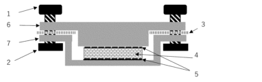
- FIG. 2 is a schematic diagram of a cross section of a pressure cell used for measuring the ionic conductivity of a solid electrolyte mixture sheet in the examples.
- the present disclosure provides a tetrafluoroethylene-based polymer for use in a binder for electrochemical devices, the tetrafluoroethylene-based polymer having an extrusion pressure of 100 MPa or less at a reduction ratio of 2500 and substantially free of moisture.
- the tetrafluoroethylene (TFE)-based polymer of the present disclosure is unlikely to generate aggregates even when kneaded for a long time with powder components of electrochemical devices such as electrode active materials and solid electrolytes, and can be mixed uniformly with the powder components. In addition, a mixture sheet having excellent strength and flexibility can be obtained.
- the TFE-based polymer of the present disclosure also does not substantially contain moisture, so it can suppress gas generation inside electrochemical device cell and deterioration of electrochemical device characteristics (for example, capacity reduction during high-temperature storage).
- the TFE-based polymer of the present disclosure also does not need to use a large amount of dispersion medium such as water or organic solvent, and can be combined with a wide range of electrode active materials and solid electrolytes, which is advantageous in production process.In addition, it can reduce the process and cost due to the use of dispersion medium.
- the TFE-based polymer of the present disclosure has excellent binding strength with active materials and electrolytes, the amount of the polymer used can be reduced.
- the TFE-based polymer may be a homopolymer of TFE, or a TFE copolymer containing polymerization units based on TFE (TFE units) and polymerization units based on a modified monomer copolymerizable with TFE (modified monomer units).
- the TFE-based polymer may be polytetrafluoroethylene (PTFE).
- the PTFE may be a homopolymer of tetrafluoroethylene (TFE) or a modified PTFE.
- a homopolymer of TFE refers to a polymer in which the content of polymerized units based on modified monomers copolymerizable with TFE in the total polymerized units is less than 0.0001 mass%.
- the modified PTFE contains polymerization units based on TFE (TFE units) and modified monomer units.
- TFE units polymerization units based on TFE (TFE units) and modified monomer units.
- the modified PTFE may contain 99.0% by mass or more of TFE units and 1.0% by mass or less of modified monomer units.
- the modified PTFE may also consist of only TFE units and modified monomer units.
- the above TFE copolymer may consist only of TFE units and modified monomer units.
- the TFE-based polymer can be mixed more uniformly with the powder components of the electrochemical device, and the content of the modified monomer unit is preferably in the range of 0.0001 to 10 mass% relative to the total polymerization units, since it can obtain a composite sheet with better strength and flexibility.
- the lower limit of the content of the modified monomer unit is more preferably 0.001 mass%, more preferably 0.010 mass%, and even more preferably 0.050 mass%.
- the upper limit of the content of the modified monomer unit is preferably 5.0 mass%, more preferably 3.0 mass%, more preferably 1.0 mass%, even more preferably 0.80 mass%, even more preferably 0.60 mass%, even more preferably 0.40 mass%, even more preferably 0.30 mass%, and particularly preferably 0.25 mass%.
- the modified monomer unit means a portion of the molecular structure of a TFE-based polymer that is derived from a modified monomer.
- the content of each of the above-mentioned polymerized units can be calculated by appropriately combining NMR, FT-IR, elemental analysis, and X-ray fluorescence analysis depending on the type of monomer.
- the modified monomer is not particularly limited as long as it can be copolymerized with TFE, and examples thereof include perfluoroolefins such as hexafluoropropylene [HFP]; hydrogen-containing fluoroolefins such as trifluoroethylene and vinylidene fluoride [VDF]; perhaloolefins such as chlorotrifluoroethylene [CTFE]; perfluorovinyl ethers; perfluoroallyl ethers; (perfluoroalkyl)ethylenes, ethylenes, etc.
- the modified monomers used may be one type or multiple types.
- Rf1 represents a perfluoro organic group.
- the "perfluoro organic group” refers to an organic group in which all hydrogen atoms bonded to carbon atoms are replaced with fluorine atoms.
- the perfluoro organic group may have an ether oxygen.
- perfluorovinyl ether is perfluoro(alkyl vinyl ether) [PAVE], where Rf 1 in the general formula (A) is a perfluoroalkyl group having 1 to 10 carbon atoms.
- the number of carbon atoms in the perfluoroalkyl group is preferably 1 to 5.
- Examples of the perfluoroalkyl group in the PAVE include a perfluoromethyl group, a perfluoroethyl group, a perfluoropropyl group, a perfluorobutyl group, a perfluoropentyl group, and a perfluorohexyl group.
- the perfluorovinyl ether further includes those represented by the above general formula (A), in which Rf 1 is a perfluoro(alkoxyalkyl) group having 4 to 9 carbon atoms, and those represented by the following formula:
- Rf 1 is a group represented by the following formula:
- n is an integer from 1 to 4.
- the (perfluoroalkyl)ethylene [PFAE] is not particularly limited, and examples include (perfluorobutyl)ethylene [PFBE] and (perfluorohexyl)ethylene.
- the above Rf2 is preferably a perfluoroalkyl group having 1 to 10 carbon atoms or a perfluoroalkoxyalkyl group having 1 to 10 carbon atoms.
- the above-mentioned perfluoroallyl ether is preferably at least one selected from the group consisting of CF 2 ⁇ CF-CF 2 -O-CF 3 , CF 2 ⁇ CF-CF 2 -O-C 2 F 5 , CF 2 ⁇ CF-CF 2 -O-C 3 F 7 , and CF 2 ⁇ CF-CF 2 -O-C 4 F 9 , more preferably at least one selected from the group consisting of CF 2 ⁇ CF-CF 2 -O-C 2 F 5 , CF 2 ⁇ CF-CF 2 -O-C 3 F 7 , and CF 2 ⁇ CF-CF 2 -O-C 4 F 9 , and even more preferably CF 2 ⁇ CF-CF 2 -O-CF 2 CF 2 CF 3 .
- Rf is preferably a perfluoroalkyl group having 1 to 10 carbon atoms, more preferably a perfluoroalkyl group having 1 to 5 carbon atoms, and even more preferably a perfluoroalkyl group having 1 to 4 carbon atoms.
- the modified monomer is preferably at least one selected from the group consisting of CTFE, HFP, perfluoro(methyl vinyl ether) [PMVE], perfluoro(propyl vinyl ether) [PPVE], PFBE, and VDF, more preferably at least one selected from the group consisting of CTFE, HFP, PMVE, and PPVE, even more preferably at least one selected from the group consisting of CTFE, HFP, and PPVE, and particularly preferably at least one selected from the group consisting of CTFE and HFP.
- the modified monomer is preferably at least one selected from the group consisting of CTFE, HFP, and PPVE, and particularly preferably at least one selected from the group consisting of CTFE and HEP.
- the TFE-based polymer disclosed herein preferably has a core-shell structure.
- a TFE-based polymer having a core-shell structure is used, excessive fibrillation of the TFE-based polymer is suppressed when it is mixed with the powder components of an electrochemical device, and therefore a uniform mixture can be obtained.
- An example of a TFE-based polymer having a core-shell structure is modified PTFE, which contains a core of high molecular weight PTFE and a shell of lower molecular weight PTFE or modified PTFE in the particle.
- modified PTFE is the PTFE described in JP-A-2005-527652.
- the core and the shell do not necessarily need to have a clear boundary between them, and the modified PTFE constituting the core and the modified PTFE constituting the shell may be mixed near the boundary between the core and the shell.
- the core in the above core-shell structure is preferably a modified PTFE having polymerized units based on a modified monomer.
- the modifying monomer in the core is preferably at least one selected from the group consisting of fluoro(alkyl vinyl ether), vinyl heterocycle and fluoroolefin, more preferably at least one selected from the group consisting of fluoro(alkyl vinyl ether) and fluoroolefin, even more preferably at least one selected from the group consisting of PAVE, HFP and CTFE, even more preferably at least one selected from the group consisting of PAVE and CTFE, and particularly preferably CTFE.
- PAVE perfluoro(propyl vinyl ether) [PPVE] is preferred.
- the shell in the above core-shell structure is preferably a modified PTFE having polymerized units based on a modified monomer and/or a modified PTFE obtained by polymerization using a chain transfer agent.
- the modifying monomer in the shell is preferably at least one selected from the group consisting of fluoro(alkyl vinyl ether) and fluoroolefin, more preferably at least one selected from the group consisting of PAVE, HFP and CTFE, even more preferably at least one selected from the group consisting of HFP and CTFE, and even more preferably CTFE.
- the chain transfer agent is not particularly limited as long as it reduces the molecular weight of the modified PTFE constituting the shell, and examples thereof include non-peroxide organic compounds such as water-soluble alcohols, hydrocarbons and fluorinated hydrocarbons, water-soluble organic peroxides such as disuccinic acid peroxide [DSP], and persulfates such as ammonium persulfate [APS] and potassium persulfate [KPS].
- the chain transfer agent may be any one that contains at least one of a non-peroxide organic compound, a water-soluble organic peroxide, and a persulfate. In the chain transfer agent, one or more of each of the non-peroxide organic compounds, the water-soluble organic peroxides and the persulfates can be used.
- the chain transfer agent is preferably at least one selected from the group consisting of water-soluble alcohols having 1 to 4 carbon atoms, hydrocarbons having 1 to 4 carbon atoms, and fluorohydrocarbons having 1 to 4 carbon atoms, in terms of good dispersibility and uniformity in the reaction system, more preferably at least one selected from the group consisting of methane, ethane, n-butane, isobutane, methanol, HFC-134a, HFC-32, DSP, APS, and KPS, even more preferably methanol and/or isobutane, and particularly preferably methanol.
- the TFE-based polymer of the present disclosure is substantially free of moisture. This can suppress gas generation and deterioration of electrochemical device properties. In addition, it is advantageous in terms of production process because it can be combined with a wide range of electrode active materials and solid electrolytes.
- Substantially free of moisture means that the moisture content of the TFE-based polymer is 0.050 mass% or less.
- the moisture content is preferably 0.020% by mass or less, more preferably 0.010% by mass or less, even more preferably 0.005% by mass or less, even more preferably 0.003% by mass or less, even more preferably 0.002% by mass or less, and even more preferably 0.001% by mass or less.
- the water content is measured by the following method.
- the TFE-based polymer of the present disclosure is preferably substantially free of fluorine-containing compounds having a molecular weight of not more than 1000.
- substantially free of fluorine-containing compounds means that the amount of the fluorine-containing compounds is not more than 25 ppb by mass relative to the TFE-based polymer.
- the amount of the fluorine-containing compound is preferably 20 mass ppb or less, more preferably 15 mass ppb or less, even more preferably 10 mass ppb or less, even more preferably less than 10 mass ppb, even more preferably 1 mass ppb or less, even more preferably less than 1 mass ppb, and particularly preferably less than the lower limit of quantification.
- the lower limit is not particularly limited, and may be an amount less than the lower limit of quantification.
- the amount of the fluorine-containing compound having a molecular weight of 1,000 or less is measured by the following method. Weigh out 1 g of the sample, add 10 g (12.6 ml) of methanol, and perform ultrasonic treatment for 60 minutes to obtain an extract. The obtained extract is appropriately concentrated with nitrogen purge, and the fluorine-containing compounds in the concentrated extract are measured by LC/MS/MS. Molecular weight information is extracted from the obtained LC/MS spectrum, and the agreement with the structural formula of the candidate fluorine-containing compound is confirmed. Prepare aqueous solutions with 5 or more levels of content of the standard substance, perform LC/MS analysis of the aqueous solutions with each content, plot the relationship between the content and the area area for that content, and draw a calibration curve. Using the above calibration curve, the area area of the LC/MS chromatogram of the fluorine-containing compound in the extract is converted to the content of the fluorine-containing compound. The lower limit of quantification in this measurement method is 10 ppb by mass.
- Examples of the fluorine-containing compound having a molecular weight of 1000 or less include a fluorine-containing compound having a hydrophilic group and a molecular weight of 1000 g/mol or less.
- the molecular weight of the fluorine-containing compound is preferably 800 or less, and more preferably 500 or less.
- Polymer particles obtained by polymerization in the presence of a fluorine-containing surfactant usually contain a fluorine-containing surfactant in addition to a TFE-based polymer. In this specification, the fluorine-containing surfactant is one used during polymerization.
- the fluorine-containing compound having a molecular weight of 1,000 or less may be a compound that has not been added during polymerization, for example, a compound that is generated as a by-product during polymerization.
- the fluorine-containing compound having a molecular weight of 1000 or less contains an anionic moiety and a cationic moiety, it means a compound containing fluorine in which the molecular weight of the anionic moiety is 1000 or less.
- the fluorine-containing compound having a molecular weight of 1000 or less does not include TFE-based polymers.
- the hydrophilic group may be, for example, -COOM, -SO 2 M, or -SO 3 M, and examples of such anionic groups include -COOM and -SO 3 M (in each formula, M is H, a metal atom, NR 1 4 , an imidazolium which may have a substituent, a pyridinium which may have a substituent, or a phosphonium which may have a substituent, and R 1 is H or an organic group).
- a surfactant containing fluorine in which the molecular weight of the anionic portion is 1000 or less can also be used.
- the "anionic portion” refers to the portion of the fluorine-containing surfactant excluding the cation. For example, in the case of F(CF 2 ) n1 COOM, it is the portion "F(CF 2 ) n1 COO".
- the anionic fluorine-containing surfactant may be a compound represented by the following general formula (N 0 ): X n0 - Rf n0 - Y 0 (N 0 ) (In the formula, X n0 is H, Cl or F.
- Rf n0 is a linear, branched or cyclic alkylene group having 3 to 20 carbon atoms in which some or all of the H's are substituted with F, and the alkylene group may contain one or more ether bonds, and some of the H's may be substituted with Cl.
- Y 0 is an anionic group. The anionic group of Y 0 may be -COOM, -SO 2 M or -SO 3 M, and may be -COOM or -SO 3 M.
- M is H, a metal atom, NR 1 4 , an imidazolium which may have a substituent, a pyridinium which may have a substituent, or a phosphonium which may have a substituent, and R 1 is H or an organic group.
- the metal atom includes alkali metals (Group 1) and alkaline earth metals (Group 2), such as Na, K, or Li.
- R 1 may be H or a C 1-10 organic group, may be H or a C 1-4 organic group, or may be H or a C 1-4 alkyl group.
- M may be H, a metal atom or NR 1 4 , which may be H, an alkali metal (group 1), an alkaline earth metal (group 2) or NR 1 4 , which may be H, Na, K, Li or NH 4 .
- Rf n0 may be one in which 50% or more of H is substituted with fluorine.
- the above-mentioned fluorine-containing surfactant may be one type of fluorine-containing surfactant or a mixture containing two or more types of fluorine-containing surfactants.
- fluorine-containing surfactant examples include compounds represented by the following formula:
- the fluorine-containing surfactant may be a mixture of these compounds.
- M may be H, a metal atom or NR 1 4 , which may be H, an alkali metal (group 1), an alkaline earth metal (group 2) or NR 1 4 , which may be H, Na, K, Li or NH 4 .
- R 1 may be H or a C 1-10 organic group, may be H or a C 1-4 organic group, may be H or a C 1-4 alkyl group.
- the TFE-based polymer of the present disclosure is substantially free of any of the fluorine-containing compounds represented by the above formulas, gas generation and deterioration of the electrochemical device properties can be further suppressed.
- substantially free of any of the fluorine-containing compounds represented by the above formulas means that the amount of the fluorine-containing compounds is 25 ppb by mass or less relative to the TFE-based polymer.
- the amount of the fluorine-containing compound is preferably 20 mass ppb or less, more preferably 15 mass ppb or less, even more preferably 10 mass ppb or less, even more preferably less than 10 mass ppb, even more preferably 1 mass ppb or less, even more preferably less than 1 mass ppb, and particularly preferably less than the lower limit of quantification.
- the lower limit is not particularly limited, and may be an amount less than the lower limit of quantification.
- the TFE-based polymers of the present disclosure have the following general formula: [C n-1 F 2n-1 COO - ]M + (wherein n is an integer of 9 to 14, preferably an integer of 9 to 12, and M + represents a cation.) This makes it possible to further suppress gas generation and deterioration of the electrochemical device characteristics.
- M constituting the cation M + is the same as M described above.
- “Substantially free of the fluorine-containing compound represented by the above formula” means that the amount of the fluorine-containing compound is 25 ppb by mass or less relative to the TFE-based polymer.
- the amount of the fluorine-containing compound is preferably 20 mass ppb or less, more preferably 15 mass ppb or less, even more preferably 10 mass ppb or less, even more preferably less than 10 mass ppb, even more preferably 1 mass ppb or less, even more preferably less than 1 mass ppb, and particularly preferably less than the lower limit of quantification.
- the lower limit is not particularly limited, and may be an amount less than the lower limit of quantification.
- the TFE-based polymer of the present disclosure can be mixed more uniformly with the powder components of an electrochemical device, and a composite sheet having more excellent strength and flexibility can be obtained, so that the endothermic peak temperature is preferably 320° C. or higher, more preferably 325° C. or higher, even more preferably 330° C. or higher, and even more preferably 333° C. or higher.
- the endothermic peak temperature is also preferably 350° C. or lower, more preferably 345° C. or lower, and even more preferably 340° C. or lower.
- the endothermic peak temperature is a temperature corresponding to a minimum point in a heat of fusion curve obtained by carrying out differential scanning calorimetry (DSC) at a heating rate of 2° C./min on a TFE-based polymer that has not been heated to a temperature of 300° C. or higher.
- DSC differential scanning calorimetry
- each of them is regarded as an endothermic peak temperature.
- the TFE-based polymer of the present disclosure preferably has non-melt secondary processability.
- the above-mentioned non-melt secondary processability means that the melt flow rate cannot be measured at a temperature higher than the melting point in accordance with ASTM D-1238 and D-2116, in other words, that the polymer does not flow easily even in the melting temperature range.
- the TFE-based polymer of the present disclosure preferably has a standard specific gravity (SSG) of 2.200 or less, more preferably 2.190 or less, even more preferably 2.180 or less, and even more preferably 2.175 or less, in order to enable more uniform mixing with the powder components of an electrochemical device; and preferably has an SSG of 2.130 or more, more preferably 2.140 or more, even more preferably 2.150 or more, 2.155 or more, or 2.160 or more, in order to enable a composite sheet having even greater strength and flexibility to be obtained.
- SSG is measured by a water displacement method according to ASTM D 792 using a sample molded according to ASTM D 4895.
- the TFE-based polymer of the present disclosure has an extrusion pressure of 100 MPa or less at a reduction ratio (RR) of 2500.
- the extrusion pressure at RR2500 is preferably 95 MPa or less, more preferably 90 MPa or less, even more preferably 80 MPa or less, even more preferably 75 MPa or less, even more preferably 70 MPa or less, even more preferably 65 MPa or less, and in terms of being able to obtain a mixture sheet having better strength and flexibility, it is more preferably 35 MPa or more, more preferably 40 MPa or more, and even more preferably 45 MPa or more.
- the extrusion pressure in RR2500 is measured by the following method.
- the form of the TFE-based polymer disclosed herein is not limited, but it is preferably a powder since it can be mixed with the electrode active material and solid electrolyte without using a large amount of dispersion medium.
- the TFE-based polymer of the present disclosure may have an average secondary particle size of 350 ⁇ m or more, preferably 400 ⁇ m or more, more preferably 450 ⁇ m or more, and even more preferably 500 ⁇ m or more, and also preferably 1000 ⁇ m or less, more preferably 900 ⁇ m or less, even more preferably 800 ⁇ m or less, and even more preferably 700 ⁇ m or less.
- the average secondary particle size is measured in accordance with JIS K 6891.
- the TFE-based polymer of the present disclosure preferably has an apparent density of 0.40 g/ml or more, more preferably 0.43 g/ml or more, and even more preferably 0.45 g/ml or more.
- the upper limit is not particularly limited, but may be 0.70 g/ml.
- the apparent density is measured in accordance with JIS K6892.
- the TFE-based polymer of the present disclosure can be suitably produced, for example, by a production method including a step (A) of obtaining an aqueous dispersion containing a TFE-based polymer and an aqueous medium by polymerizing tetrafluoroethylene (TFE) in an aqueous medium, a step (B) of coagulating the aqueous dispersion after mixing to obtain a wet powder, and a step (C) of drying the wet powder.
- a production method including a step (A) of obtaining an aqueous dispersion containing a TFE-based polymer and an aqueous medium by polymerizing tetrafluoroethylene (TFE) in an aqueous medium, a step (B) of coagulating the aqueous dispersion after mixing to obtain a wet powder, and a step (C) of drying the wet powder.
- the aqueous dispersion in step (A) can also be suitably produced by carrying out a step (1a) of feeding the modified monomer into the reaction system at the beginning of the polymerization reaction in the step of emulsion polymerizing TFE and the modified monomer, and a step (2a) of introducing a chain transfer agent and/or a modified monomer into the reaction system after the step (1a).
- a step (1a) of feeding the modified monomer into the reaction system at the beginning of the polymerization reaction in the step of emulsion polymerizing TFE and the modified monomer and a step (2a) of introducing a chain transfer agent and/or a modified monomer into the reaction system after the step (1a).
- modified monomer in step (1a) examples include fluoro(alkyl vinyl ethers) such as perfluoro(alkyl vinyl ether) [PAVE]; vinyl heterocyclic compounds such as perfluoro-2,2-dimethyl-1,3-dioxole [PDD]; and fluoroolefins such as hexafluoropropylene [HFP] and chlorotrifluoroethylene [CTFE].
- fluoro(alkyl vinyl ethers) such as perfluoro(alkyl vinyl ether) [PAVE]
- vinyl heterocyclic compounds such as perfluoro-2,2-dimethyl-1,3-dioxole [PDD]
- fluoroolefins such as hexafluoropropylene [HFP] and chlorotrifluoroethylene [CTFE].
- HFP hexafluoropropylene
- CTFE chlorotrifluoroethylene
- At least one selected from the group consisting of fluoro(alkyl vinyl ether)s and fluoroolefins is preferred, at least one selected from the group consisting of PAVE, HFP, and CTFE is more preferred, at least one selected from the group consisting of PAVE and CTFE is even more preferred, and CTFE is even more preferred. It is also preferable to use PAVE and HFP in combination as the modifying monomers in step (1a).
- the PAVE is preferably perfluoro(propyl vinyl ether) [PPVE].
- the chain transfer agent in step (2a) is not particularly limited as long as it reduces the molecular weight of the modified PTFE constituting the shell of the core-shell structure, and examples thereof include non-peroxide organic compounds such as water-soluble alcohols, hydrocarbons and fluorinated hydrocarbons, water-soluble organic peroxides such as disuccinic acid peroxide [DSP], and persulfates such as ammonium persulfate [APS] and potassium persulfate [KPS].
- the chain transfer agent may be any one that contains at least one of a non-peroxide organic compound, a water-soluble organic peroxide, and a persulfate. In the chain transfer agent, one or more of each of the non-peroxide organic compounds, the water-soluble organic peroxides and the persulfates can be used.
- the chain transfer agent is preferably at least one selected from the group consisting of water-soluble alcohols having 1 to 4 carbon atoms, hydrocarbons having 1 to 4 carbon atoms, and fluorohydrocarbons having 1 to 4 carbon atoms, in terms of good dispersibility and uniformity in the reaction system, more preferably at least one selected from the group consisting of methane, ethane, n-butane, isobutane, methanol, HFC-134a, HFC-32, DSP, APS, and KPS, even more preferably methanol and/or isobutane, and particularly preferably methanol.
- the modified monomer in step (2a) is preferably at least one selected from the group consisting of the above-mentioned fluoro(alkyl vinyl ether) and fluoroolefin, more preferably at least one selected from the group consisting of PAVE, HFP, and CTFE, even more preferably at least one selected from the group consisting of HFP and CTFE, and even more preferably CTFE.
- step (2a) it is also preferable to use the chain transfer agent and the modified monomer in combination.
- CTFE When CTFE is used as the modifying monomer in step (1a), it is preferable to use CTFE as the modifying monomer in step (2a).
- PAVE (and HFP) are used as the modifying monomer in step (1a)
- methanol (and HFP as the modifying monomer) As the chain transfer agent in step (2a).
- step (1a) it is preferable to carry out the polymerization reaction until the conversion rate of TFE used in the entire emulsion polymerization process including the step (1a) and the step (2a) reaches 80% or more, preferably 80 to 97%, and more preferably 85 to 95%.
- conversion rate refers to the ratio of the amount of TFE consumed in the polymerization from the start of polymerization to a certain point during the polymerization to the amount of TFE corresponding to the target amount of TFE units.
- reaction conditions can be appropriately set depending on the type of modifier used, the composition and yield of the desired TFE-based polymer, etc.
- the emulsion polymerization can be carried out in an aqueous medium in the presence of an anionic fluorine-containing surfactant and a polymerization initiator. If necessary, a dispersion stabilizer and the like may be used.
- the amount of the anionic fluorine-containing surfactant may be 0.02 to 0.3% by mass of the aqueous medium.
- polymerization initiator for example, persulfates such as ammonium persulfate [APS], water-soluble organic peroxides such as disuccinic acid peroxide [DSP], etc. can be used, and these polymerization initiators can be used alone or in combination of two or more. Among them, APS, DSP, etc. are preferred because they also act as the above-mentioned chain transfer agent.
- the emulsion polymerization is preferably carried out in an amount of 0.0001 to 0.02 parts by mass of the polymerization initiator per 100 parts by mass of the aqueous medium.
- the above-mentioned aqueous medium can be used.
- the emulsion polymerization can be carried out at a polymerization temperature of 10 to 95°C, but when a persulfate or a water-soluble organic peroxide is used as the polymerization initiator, it is preferably carried out at a temperature of 60 to 90°C.
- the emulsion polymerization can be carried out usually at a pressure of 0.5 to 3.9 MPaG, preferably 0.6 to 3 MPaG.
- the emulsion polymerization can also be carried out by carrying out the reaction at a pressure of 0.5 MPaG or less in the early stage of the polymerization, particularly until the conversion rate of the TFE-based polymer reaches 15% or less of the total, and then maintaining the pressure at a level exceeding 0.5 MPaG.
- the reaction pressure can be reduced to, for example, 0.1 MPaG or less during the formation of the core, and TFE is again supplied to carry out the reaction at a predetermined pressure.
- step (A) can be carried out by a known method.
- the coagulation in step (B) can be carried out by a known method.
- step (C) the drying is usually carried out by using a vacuum, high frequency, hot air or other means while keeping the wet powder in a state where it is not very fluid, preferably in a stationary state.
- Friction between powders, especially at high temperatures, generally has an undesirable effect on fine powder-type TFE-based polymers. This is because particles made of this type of TFE-based polymer tend to easily become fibrillated even by small shear forces, losing their original stable particle structure.
- step (C) it is preferable to place the wet powder obtained in step (B) in a container with air permeability at the bottom and/or sides, and heat treat it at a temperature of 130 to 300°C for 2 hours or more.
- the fluorine-containing compound having a molecular weight of 1000 or less can be efficiently removed together with water, and the content of the fluorine-containing compound and water can be kept within the above-mentioned range.
- the temperature of the heat treatment in step (C) is preferably 140°C or higher, more preferably 150°C or higher, even more preferably 160°C or higher, even more preferably 180°C or higher, even more preferably 200°C or higher, particularly preferably 220°C or higher, and is preferably 280°C or lower, more preferably 250°C or lower, in order to more efficiently remove moisture and fluorine-containing compounds.
- the time for the heat treatment in step (C) is preferably 5 hours or more, more preferably 10 hours or more, and even more preferably 15 hours or more, in order to more efficiently remove moisture and fluorine-containing compounds.
- the wind speed in step (C) is preferably 0.01 m/s or more, more preferably 0.03 m/s or more, even more preferably 0.05 m/s or more, and even more preferably 0.1 m/s or more, from the viewpoint of more efficiently removing moisture and fluorine-containing compounds. Also, from the viewpoint of suppressing scattering of powder, it is preferably 50 m/s or less, more preferably 30 m/s or less, and even more preferably 10 m/s or less.
- the heat treatment in step (C) can be carried out using an electric furnace or a steam furnace.
- electric furnaces such as a parallel flow box type electric furnace, a ventilated box type electric furnace, a ventilated conveyor type electric furnace, a band electric furnace, a radiant conveyor type electric furnace, a fluidized bed electric furnace, a vacuum electric furnace, an agitator type electric furnace, an airflow type electric furnace, or a hot air circulation type electric furnace, or a steam furnace corresponding to the above (a device obtained by replacing the electric furnace in the device name of each electric furnace with a steam furnace).
- a parallel flow box type electric furnace In terms of being able to remove moisture and fluorine-containing compounds more efficiently, a parallel flow box type electric furnace, a ventilated box type electric furnace, a ventilated conveyor type electric furnace, a band electric furnace, a fluidized bed electric furnace, a hot air circulation type electric furnace, or a steam furnace corresponding to the above (a device obtained by replacing the electric furnace in the device name of each electric furnace with a steam furnace) is preferred.
- the heat treatment in step (C) is preferably carried out by placing the wet powder in a container having air permeability at its bottom and/or sides, in order to more efficiently remove moisture and the fluorine-containing compound.
- the container having air permeability at its bottom and/or sides may be any container that can withstand the heat treatment temperature, and is preferably made of a metal such as stainless steel.
- a tray (bat) having breathability on the bottom and/or sides is preferable, and a tray whose bottom and/or sides are made of mesh (mesh tray) is more preferable.
- the mesh is preferably either a woven mesh or a punched metal.
- the mesh size is preferably 2000 ⁇ m or less (ASTM standard 10 mesh or more), more preferably 595 ⁇ m or less (30 mesh or more), even more preferably 297 ⁇ m or less (50 mesh or more), even more preferably 177 ⁇ m or less (80 mesh or more), particularly preferably 149 ⁇ m or less (100 mesh or more), and particularly preferably 74 ⁇ m or less (200 mesh or more). Also, 25 ⁇ m or more (500 mesh or less) is preferable.
- the weaving method may be, for example, plain weave, twill weave, plain tatami weave, or twill tatami weave.
- the opening rate is preferably 10% or more, more preferably 20% or more, and even more preferably 30% or more, and is preferably 95% or less.
- the amount of the moist powder disposed is, from the viewpoint of more efficiently removing moisture and fluorine-containing compounds, preferably 10 g/ cm2 or less, more preferably 8 g/ cm2 or less, even more preferably 5 g/ cm2 or less, particularly preferably 3 g/ cm2 or less, and is preferably 0.01 g/ cm2 or more, more preferably 0.05 g/ cm2 or more, and even more preferably 0.1 g/ cm2 or more.
- the moisture content of the moist powder to be heat-treated in step (C) is preferably 10% by mass or more, more preferably 20% by mass or more, and even more preferably 30% by mass or more, relative to the moist powder, in order to more efficiently remove moisture and fluorine-containing compounds, and is preferably 150% by mass or less, and more preferably 100% by mass or less.
- the TFE-based polymer of the present disclosure is used in a binder for electrochemical devices.
- the TFE-based polymer of the present disclosure may be used alone or in a mixture with other materials (e.g., polymers other than TFE-based polymers).
- other materials e.g., polymers other than TFE-based polymers.
- the present disclosure also provides a binder for electrochemical devices consisting essentially of a TFE-based polymer, the TFE-based polymer having an extrusion pressure of 100 MPa or less at a reduction ratio of 2500, and containing substantially no moisture.
- the binder of the present disclosure is unlikely to generate aggregates even when kneaded for a long time with powder components of electrochemical devices such as electrode active materials and solid electrolytes, and can be mixed uniformly with the powder components.
- a mixture sheet having excellent strength and flexibility can be obtained.
- the binder of the present disclosure is substantially free of moisture, and therefore can suppress gas generation inside an electrochemical device cell and deterioration of the electrochemical device characteristics (for example, reduction in capacity during storage at high temperatures).
- the binder of the present disclosure is also advantageous in terms of production process because it does not require the use of a large amount of a dispersion medium such as water or an organic solvent, and a wide range of electrode active materials and solid electrolytes can be selected for combination with the binder, and the process and cost involved in using a dispersion medium can be reduced. Furthermore, since the binder of the present disclosure has excellent binding strength with the active material and the electrolyte, the amount of the binder used can be reduced.
- the TFE-based polymer in the binder of the present disclosure can be the same as the TFE-based polymer of the present disclosure described above, and the preferred embodiments are also the same.
- the binder of the present disclosure is substantially composed of the TFE-based polymer. This allows the effect of the TFE-based polymer to be significantly exhibited.
- “Substantially composed of the TFE-based polymer” means that the content of the TFE-based polymer is 95.0 mass% or more with respect to the binder.
- the content of the TFE-based polymer relative to the binder is preferably 98.0% by mass or more, more preferably 99.0% by mass or more, even more preferably 99.5% by mass or more, particularly preferably 99.9% by mass or more, and most preferably 99.95% by mass or more. It is also preferred that the binder of the present disclosure consists solely of the TFE-based polymer.
- the binder of the present disclosure is preferably substantially free of organic solvent. This can reduce the steps and costs associated with the use of organic solvent. "Substantially free of organic solvent” means that the organic solvent content of the binder is 5% by mass or less.
- the organic solvent content is preferably 3% by mass or less, more preferably 1% by mass or less, even more preferably 0.1% by mass or less, even more preferably 0.01% by mass or less, and particularly preferably 0.001% by mass or less.
- the binder of the present disclosure is preferably in the form of a powder.
- the binders of the present disclosure are used in electrochemical devices such as batteries and capacitors.
- the battery may be a secondary battery such as a lithium ion battery.
- the capacitor is not particularly limited, but is preferably an electrochemical capacitor.
- the electrochemical capacitor include an electric double layer capacitor, a hybrid capacitor, and a redox capacitor.
- the hybrid capacitor include a sodium ion capacitor, a lithium ion capacitor, and a magnesium ion capacitor. Among these, an electric double layer capacitor is particularly preferred.
- the binder of the present disclosure can be suitably used as a binder for batteries or binders for capacitors, and can be more suitably used as a binder for secondary batteries such as lithium ion batteries.
- the binders of the present disclosure may be used to fabricate battery components.
- the binder of the present disclosure can be particularly suitably used as a binder for electrodes.
- the binder of the present disclosure can also be suitably used as a binder in the solid electrolyte layer of a solid secondary battery.
- the present disclosure also provides an electrode mixture containing the above-mentioned TFE-based polymer of the present disclosure or the binder of the present disclosure and an electrode active material.
- the electrode mixture of the present disclosure is used, the powder components of the electrochemical device are uniformly dispersed, and a mixture sheet having excellent strength and flexibility is obtained. Furthermore, even if the amount of binder is small, the electrode active material can be held, so that more materials that improve the electrochemical device characteristics, such as active materials and conductive assistants, can be added.
- the above-mentioned electrode active materials include positive electrode active materials and negative electrode active materials.
- the positive electrode active material is not particularly limited as long as it can electrochemically absorb and release alkali metal ions, but for example, a material containing an alkali metal and at least one transition metal is preferred. Specific examples include alkali metal-containing transition metal complex oxides and alkali metal-containing transition metal phosphate compounds. In particular, alkali metal-containing transition metal complex oxides that generate high voltage are preferred as the positive electrode active material. Examples of the alkali metal ions include lithium ions, sodium ions, potassium ions, and the like. In a preferred embodiment, the alkali metal ions may be lithium ions. That is, in this embodiment, the alkali metal ion secondary battery is a lithium ion secondary battery.
- alkali metal-containing transition metal composite oxide examples include: Formula: M a Mn 2-b M 1 b O 4 (wherein M is at least one metal selected from the group consisting of Li, Na, and K; 0.9 ⁇ a; 0 ⁇ b ⁇ 1.5; M1 is at least one metal selected from the group consisting of Fe, Co, Ni, Cu, Zn, Al, Sn, Cr, V, Ti, Mg, Ca, Sr, B, Ga, In, Si, and Ge), an alkali metal-manganese spinel composite oxide (such as a lithium-manganese spinel composite oxide), Formula: MNi 1-c M 2 c O 2 (wherein M is at least one metal selected from the group consisting of Li, Na, and K; 0 ⁇ c ⁇ 0.5; M2 is at least one metal selected from the group consisting of Fe, Co, Mn, Cu, Zn, Al, Sn, Cr, V, Ti, Mg, Ca, Sr, B, Ga, In, Si, and Ge), or an alkal
- MCoO2 , MMnO2 , MNiO2 , MMn2O4 , MNi0.8Co0.15Al0.05O2 , MNi1 / 3Co1/3Mn1 / 3O2 , etc. are preferred, and a compound represented by the following general formula (3) is preferable.
- M is at least one metal selected from the group consisting of Li, Na, and K
- the alkali metal-containing transition metal phosphate compound is, for example, a compound represented by the following general formula (4): M e M 4 f (PO 4 ) g (4) (wherein M is at least one metal selected from the group consisting of Li, Na and K, and M4 is at least one selected from the group consisting of V, Ti, Cr, Mn, Fe, Co, Ni and Cu, and 0.5 ⁇ e ⁇ 3, 1 ⁇ f ⁇ 2, 1 ⁇ g ⁇ 3).
- M is preferably at least one metal selected from the group consisting of Li, Na and K, more preferably Li or Na, and even more preferably Li. That is, the alkali metal-containing transition metal phosphate compound is preferably a lithium-containing transition metal phosphate compound.
- the transition metal of the lithium-containing transition metal phosphate compound is preferably V, Ti, Cr, Mn, Fe, Co, Ni, Cu, etc., and specific examples thereof include iron phosphates such as LiFePO4 , Li3Fe2 ( PO4 ) 3 , and LiFeP2O7 , cobalt phosphates such as LiCoPO4 , and lithium transition metal phosphate compounds in which a part of the transition metal atoms that constitute the main part of the lithium transition metal phosphate compound is replaced with other elements such as Al, Ti, V, Cr, Mn, Fe, Co, Li, Ni, Cu, Zn, Mg, Ga, Zr, Nb, and Si.
- the lithium-containing transition metal phosphate compound is preferably one having an olivine structure.
- the positive electrode active material include lithium-nickel-based composite oxides.
- the lithium-nickel-based composite oxides are represented by the following general formula (5): Li y Ni 1-x M x O 2 (5) (wherein x is 0.01 ⁇ x ⁇ 0.7, y is 0.9 ⁇ y ⁇ 2.0, and M is a metal atom (excluding Li and Ni)) is preferred.
- positive electrode active material examples include MFePO 4 , MNi 0.8 Co 0.2 O 2 , M 1.2 Fe 0.4 Mn 0.4 O 2 , MNi 0.5 Mn 1.5 O 2 , MV 3 O 6 , and M 2 MnO 3 .
- positive electrode active materials such as M 2 MnO 3 and MNi 0.5 Mn 1.5 O 2 are preferred in that the crystal structure does not collapse even when the secondary battery is operated at a voltage exceeding 4.4 V or a voltage of 4.6 V or more.
- electrochemical devices such as secondary batteries using positive electrode materials containing the above-mentioned positive electrode active materials are preferred because the remaining capacity is not easily reduced and the resistance increase rate is not easily changed even when stored at high temperatures, and the battery performance is not deteriorated even when operated at high voltages.
- the positive electrode active material include a solid solution material of M2MnO3 and MM6O2 (wherein M is at least one metal selected from the group consisting of Li, Na, and K, and M6 is a transition metal such as Co, Ni, Mn, or Fe).
- an example of the solid solution material is an alkali metal manganese oxide represented by the general formula Mx[Mn (1-y) M7y ] Oz , where M in the formula is at least one metal selected from the group consisting of Li, Na, and K, and M7 is at least one metal element other than M and Mn, and contains, for example, one or more elements selected from the group consisting of Co, Ni, Fe, Ti, Mo, W, Cr, Zr, and Sn.
- the values of x, y, and z in the formula are in the ranges of 1 ⁇ x ⁇ 2, 0 ⁇ y ⁇ 1, and 1.5 ⁇ z ⁇ 3.
- manganese -containing solid solution materials such as Li1.2Mn0.5Co0.14Ni0.14O2, which are based on Li2MnO3 and contain LiNiO2 or LiCoO2 as a solid solution , are preferred because they can provide an alkali metal ion secondary battery having a high energy density.
- lithium phosphate in the positive electrode active material, since this improves the continuous charging characteristics.
- the amount of lithium phosphate used is preferably 0.1% by mass or more, more preferably 0.3% by mass or more, and even more preferably 0.5% by mass or more, with respect to the total of the positive electrode active material and lithium phosphate, and is preferably 10% by mass or less, more preferably 8% by mass or less, and even more preferably 5% by mass or less.
- a material having a different composition may be attached to the surface of the positive electrode active material.
- surface-attached materials include oxides such as aluminum oxide, silicon oxide, titanium oxide, zirconium oxide, magnesium oxide, calcium oxide, boron oxide, antimony oxide, and bismuth oxide; sulfates such as lithium sulfate, sodium sulfate, potassium sulfate, magnesium sulfate, calcium sulfate, and aluminum sulfate; carbonates such as lithium carbonate, calcium carbonate, and magnesium carbonate; and carbon.
- These surface-attaching substances can be attached to the surface of the positive electrode active material by, for example, dissolving or suspending them in a solvent, impregnating and adding them to the positive electrode active material, and drying them; dissolving or suspending a surface-attaching substance precursor in a solvent, impregnating and adding them to the positive electrode active material, and then reacting them by heating or the like; or adding them to a positive electrode active material precursor and simultaneously baking them.
- attaching carbon a method can also be used in which the carbonaceous material is mechanically attached later in the form of, for example, activated carbon.
- the amount of the surface-attached substance is preferably 0.1 ppm or more, more preferably 1 ppm or more, and even more preferably 10 ppm or more, and preferably 20% or less, more preferably 10% or less, and even more preferably 5% or less, by mass relative to the positive electrode active material.
- the surface-attached substance can suppress the oxidation reaction of the electrolyte on the surface of the positive electrode active material, thereby improving the battery life, but if the amount of attachment is too small, the effect is not fully manifested, and if it is too large, the movement of lithium ions is inhibited, which may increase resistance.
- the shape of the particles of the positive electrode active material may be, as conventionally used, a block, polyhedron, sphere, oval sphere, plate, needle, column, etc. Primary particles may also aggregate to form secondary particles.
- the tap density of the positive electrode active material is preferably 0.5 g/cm 3 or more, more preferably 0.8 g/cm 3 or more, and even more preferably 1.0 g/cm 3 or more. If the tap density of the positive electrode active material is below the lower limit, the amount of dispersion medium required during the formation of the positive electrode active material layer increases, and the amount of conductive material and binder required increases, so that the filling rate of the positive electrode active material in the positive electrode active material layer is restricted, and the battery capacity may be restricted. By using a complex oxide powder with a high tap density, a high-density positive electrode active material layer can be formed.
- the tap density is generally preferably as high as possible, and there is no particular upper limit, but if it is too high, the diffusion of lithium ions in the positive electrode active material layer using the electrolyte as a medium becomes rate-limiting, and the load characteristics may be easily deteriorated, so the upper limit is preferably 4.0 g/cm 3 or less, more preferably 3.7 g/cm 3 or less, and even more preferably 3.5 g/cm 3 or less.
- the tap density is determined as the powder packing density (tap density) g/cm 3 when 5 to 10 g of the positive electrode active material powder is placed in a 10 ml glass measuring cylinder and tapped 200 times with a stroke of about 20 mm.
- the median diameter d50 of the particles of the positive electrode active material is preferably 0.3 ⁇ m or more, more preferably 0.5 ⁇ m or more, even more preferably 0.8 ⁇ m or more, and most preferably 1.0 ⁇ m or more, and is preferably 30 ⁇ m or less, more preferably 27 ⁇ m or less, even more preferably 25 ⁇ m or less, and most preferably 22 ⁇ m or less. If it is below the lower limit, a high tap density product may not be obtained, and if it exceeds the upper limit, it may take time for lithium to diffuse within the particles, resulting in problems such as a decrease in battery performance.
- the filling property during positive electrode production can be further improved.
- the median diameter d50 is measured by a known laser diffraction/scattering particle size distribution measuring device.
- a 0.1% by mass aqueous solution of sodium hexametaphosphate is used as the dispersion medium during the measurement, and the measurement is performed after ultrasonic dispersion for 5 minutes with a measurement refractive index set to 1.24.
- the average primary particle diameter of the positive electrode active material is preferably 0.05 ⁇ m or more, more preferably 0.1 ⁇ m or more, and even more preferably 0.2 ⁇ m or more, and the upper limit is preferably 5 ⁇ m or less, more preferably 4 ⁇ m or less, even more preferably 3 ⁇ m or less, and most preferably 2 ⁇ m or less. If the upper limit is exceeded, it is difficult to form spherical secondary particles, which may adversely affect the powder packing property or greatly reduce the specific surface area, and therefore the battery performance such as output characteristics may be likely to decrease. Conversely, if the lower limit is exceeded, problems such as poor reversibility of charge and discharge may occur due to underdeveloped crystals.
- the average primary particle diameter is measured by observation using a scanning electron microscope (SEM). Specifically, in a photograph at a magnification of 10,000 times, the longest intercept value of a horizontal line at the left and right boundaries of a primary particle is determined for any 50 primary particles, and the average value is calculated.
- SEM scanning electron microscope
- the BET specific surface area of the positive electrode active material is preferably 0.1 m2 /g or more, more preferably 0.2 m2 /g or more, and even more preferably 0.3 m2/g or more, and the upper limit is preferably 50 m2/g or less, more preferably 40 m2/g or less, and even more preferably 30 m2 /g or less. If the BET specific surface area is smaller than this range, the battery performance is likely to decrease, and if it is larger, it is difficult to increase the tap density, and problems may easily occur in the processability when forming the positive electrode active material layer.
- the BET specific surface area is defined as a value measured by a nitrogen adsorption BET single-point method using a gas flow method, using a surface area meter (e.g., a fully automatic surface area measuring device manufactured by Ohkura Riken Co., Ltd.) after pre-drying a sample at 150° C. for 30 minutes under a nitrogen flow and then using a nitrogen/helium mixed gas accurately adjusted so that the relative pressure of nitrogen to atmospheric pressure is 0.3.
- a surface area meter e.g., a fully automatic surface area measuring device manufactured by Ohkura Riken Co., Ltd.
- the particles of the positive electrode active material are mainly secondary particles. It is preferable that the particles of the positive electrode active material have an average secondary particle diameter of 40 ⁇ m or less and contain 0.5 to 7.0 volume % of fine particles with an average primary particle diameter of 1 ⁇ m or less. By containing fine particles with an average primary particle diameter of 1 ⁇ m or less, the contact area with the electrolyte is increased, and lithium ions can be diffused more quickly between the electrode mixture and the electrolyte, resulting in improved output performance of the battery.
- the manufacturing method of the positive electrode active material is a general method for manufacturing inorganic compounds.
- various methods can be considered for manufacturing spherical or elliptical active materials, for example, the raw material of transition metal is dissolved or crushed and dispersed in a solvent such as water, and the pH is adjusted while stirring to prepare spherical precursors, which are then dried as necessary, and then LiOH, Li2CO3 , LiNO3 , or other Li sources are added and calcined at high temperature to obtain active materials.
- the positive electrode active material may be used alone, or two or more different compositions may be used in any combination or ratio.
- preferred combinations include a combination of LiCoO2 and a ternary system such as LiNi0.33Co0.33Mn0.33O2 , a combination of LiCoO2 and LiMn2O4 or a combination of LiFePO4 and LiCoO2 or a combination of LiFePO4 and LiFePO2 or a combination of LiFePO4 and LiFePO2 or a combination of LiFePO4 and LiFePO2.
- the content of the positive electrode active material is preferably 50 to 99.5% by mass of the positive electrode mixture, more preferably 80 to 99% by mass, in terms of high battery capacity.
- the content in the positive electrode active material layer is preferably 80% by mass or more, more preferably 82% by mass or more, and particularly preferably 84% by mass or more.
- the upper limit is preferably 99% by mass or less, more preferably 98% by mass or less. If the content of the positive electrode active material in the positive electrode active material layer is low, the electrical capacity may be insufficient. Conversely, if the content is too high, the strength of the positive electrode may be insufficient.
- the negative electrode active material is not particularly limited, and examples thereof include lithium metal, artificial graphite, graphite carbon fiber, resin-sintered carbon, pyrolytic vapor-grown carbon, coke, mesocarbon microbeads (MCMB), furfuryl alcohol resin-sintered carbon, polyacene, pitch-based carbon fiber, vapor-grown carbon fiber, natural graphite, and carbonaceous materials such as non-graphitizable carbon, silicon-containing compounds such as silicon and silicon alloys, and Li 4 Ti 5 O 12 , or a mixture of two or more types.
- those containing at least a carbonaceous material and silicon-containing compounds can be particularly preferably used.
- the negative electrode active material used in this disclosure preferably contains silicon as a constituent element.
- a material that contains silicon as a constituent element By using a material that contains silicon as a constituent element, a high-capacity battery can be produced.
- silicon particles particles having a structure in which fine silicon particles are dispersed in a silicon-based compound, silicon oxide particles represented by the general formula SiOx (0.5 ⁇ x ⁇ 1.6), or a mixture of these are preferred.
- SiOx silicon oxide particles represented by the general formula SiOx (0.5 ⁇ x ⁇ 1.6), or a mixture of these are preferred.
- silicon oxide is a general term for amorphous silicon oxide, and silicon oxide before disproportionation is represented by the general formula SiOx (0.5 ⁇ x ⁇ 1.6).
- x is preferably 0.8 ⁇ x ⁇ 1.6, and more preferably 0.8 ⁇ x ⁇ 1.3.
- This silicon oxide can be obtained, for example, by heating a mixture of silicon dioxide and metallic silicon to produce silicon monoxide gas, which is then cooled and precipitated.
- Particles having a structure in which silicon particles are dispersed in a silicon-based compound can be obtained, for example, by firing a mixture of silicon particles and a silicon-based compound, or by heat treating silicon oxide particles before disproportionation, represented by the general formula SiOx, in an inert, non-oxidizing atmosphere such as argon at a temperature of 400°C or higher, preferably 800 to 1,100°C, to carry out a disproportionation reaction.
- the material obtained by the latter method is particularly suitable because the silicon crystallites are uniformly dispersed.
- the size of the silicon nanoparticles can be made 1 to 100 nm by the above-mentioned disproportionation reaction.
- the silicon oxide in the particles having a structure in which silicon nanoparticles are dispersed in silicon oxide is preferably silicon dioxide. Note that it is possible to confirm that silicon nanoparticles (crystals) are dispersed in amorphous silicon oxide using a transmission electron microscope.
- the physical properties of the silicon-containing particles can be appropriately selected depending on the desired composite particles.
- the average particle size is preferably 0.1 to 50 ⁇ m, with the lower limit being more preferably 0.2 ⁇ m or more, and even more preferably 0.5 ⁇ m or more.
- the upper limit is more preferably 30 ⁇ m or less, and even more preferably 20 ⁇ m or less.
- the above average particle size is represented by the weight average particle size in particle size distribution measurement by laser diffraction method.
- the BET specific surface area is preferably 0.5 to 100 m 2 /g, and more preferably 1 to 20 m 2 /g. If the BET specific surface area is 0.5 m 2 /g or more, there is no risk of the battery characteristics deteriorating due to a decrease in adhesion when applied to an electrode. On the other hand, if the BET specific surface area is 100 m 2 /g or less, the proportion of silicon dioxide on the particle surface becomes large, and there is no risk of the battery capacity deteriorating when used as a negative electrode material for a lithium ion secondary battery.
- Methods for imparting electrical conductivity include mixing the silicon-containing particles with electrically conductive particles such as graphite, coating the surfaces of the silicon-containing particles with a carbon coating, and combining both methods.
- the carbon coating method is preferred, and chemical vapor deposition (CVD) is even more preferred.
- the content of the negative electrode active material is preferably 40% by mass or more in the electrode mixture, more preferably 50% by mass or more, and particularly preferably 60% by mass or more, in order to increase the capacity of the resulting electrode mixture.
- the upper limit is preferably 99% by mass or less, more preferably 98% by mass or less.
- the electrode mixture of the present disclosure preferably further contains a conductive assistant.
- a conductive assistant Any known conductive material can be used as the conductive assistant. Specific examples include metal materials such as copper and nickel, graphite such as natural graphite and artificial graphite, carbon black such as acetylene black, ketjen black, channel black, furnace black, lamp black, and thermal black, and carbon materials such as amorphous carbon such as needle coke, carbon nanotubes, fullerene, and VGCF. These may be used alone or in any combination and ratio of two or more.
- the conductive assistant is used in an amount of usually 0.01% by mass or more, preferably 0.1% by mass or more, more preferably 1% by mass or more in the electrode mixture, and usually 50% by mass or less, preferably 30% by mass or less, more preferably 15% by mass or less. If the content is lower than this range, the conductivity may be insufficient. Conversely, if the content is higher than this range, the battery capacity may decrease.
- the electrode mixture of the present disclosure may further contain a thermoplastic resin.
- thermoplastic resin include polyvinylidene fluoride, polypropylene, polyethylene, polystyrene, polyethylene terephthalate, and polyethylene oxide.
- One type may be used alone, or two or more types may be used in any combination and ratio.
- the ratio of the thermoplastic resin to the electrode active material is usually 0.01% by mass or more, preferably 0.05% by mass or more, more preferably 0.10% by mass or more, and usually 3.0% by mass or less, preferably 2.5% by mass or less, more preferably 2.0% by mass or less. Adding the thermoplastic resin can improve the mechanical strength of the electrode. If the ratio exceeds this range, the ratio of the electrode active material in the electrode mixture decreases, which may cause problems such as a decrease in battery capacity or an increase in resistance between active materials.
- the content of the binder may be 0.1% by mass or more, preferably 0.2% by mass or more, more preferably 0.5% by mass or more, and may be 50% by mass or less, preferably 40% by mass or less, more preferably 30% by mass or less, even more preferably 10% by mass or less, particularly preferably 5% by mass or less, and most preferably 3% by mass or less. If the proportion of the binder is too low, the electrode mixture active material cannot be sufficiently held, and the mechanical strength of the electrode mixture sheet may be insufficient, which may deteriorate the battery performance such as cycle characteristics. On the other hand, if the proportion is too high, it may lead to a decrease in battery capacity and conductivity. Since the binder of the present disclosure has excellent binding strength, even if the content is small, the electrode active material can be sufficiently held.
- the binder component is preferably substantially composed of the TFE-based polymer, and more preferably of the TFE-based polymer.
- the binder component substantially composed of the TFE-based polymer means that the content of the TFE-based polymer in the binder component constituting the electrode mixture is 95.0% by mass or more relative to the binder component.
- the content of the TFE-based polymer is preferably 98.0% by mass or more relative to the binder component, more preferably 99.0% by mass or more, even more preferably 99.5% by mass or more, particularly preferably 99.9% by mass or more, and most preferably 99.95% by mass or more.
- the electrode mixture of the present disclosure is preferably in sheet form.
- the electrode mixture of the present disclosure can be suitably used as an electrode mixture for secondary batteries.
- the electrode mixture of the present disclosure is suitable for lithium ion secondary batteries.
- the electrode mixture of the present disclosure is usually used in the form of a sheet.
- the electrode mixture sheet preferably has a thickness of 300 ⁇ m or less, more preferably 250 ⁇ m or less, even more preferably 200 ⁇ m or less, even more preferably 180 ⁇ m or less, and particularly preferably 150 ⁇ m or less, and preferably 10 ⁇ m or more, more preferably 15 ⁇ m or more, and even more preferably 20 ⁇ m or more.
- the electrode mixture sheet can be obtained by a production method including a step (1) of mixing a raw material composition containing an electrode active material, a binder, and, if necessary, a conductive assistant, a step (2) of forming the raw material composition obtained by the step (1) into a bulk form, and a step (3) of rolling the bulk raw material composition obtained by the step (2) into a sheet form.
- the raw material composition is simply a mixture of the electrode active material, binder, etc., and exists in a state without a fixed shape.
- Specific mixing methods include mixing methods using a W-type mixer, V-type mixer, drum-type mixer, ribbon mixer, conical screw-type mixer, single-shaft kneader, twin-shaft kneader, mix muller, stirring mixer, planetary mixer, etc.
- the binder mixing conditions are preferably 3000 rpm or less.
- it is 10 rpm or more, more preferably 15 rpm or more, and even more preferably 20 rpm or more, and is preferably 2000 rpm or less, more preferably 1500 rpm or less, and even more preferably 1000 rpm or less. If it is below the above range, mixing will take a long time, which will affect productivity. If it is above the above range, fibrillation will proceed excessively, and the electrode mixture sheet may have poor strength and flexibility.
- forming into a bulk shape means forming the raw material composition into a single mass.
- Specific methods for forming into a bulk shape include extrusion molding, press molding, and the like.
- the term "bulk shape” does not specify a particular shape, and may refer to a state in which the raw material composition is in the form of a single mass, and includes shapes such as rods, sheets, spheres, and cubes.
- Specific rolling methods in the above step (3) include rolling using a roll press, a flat plate press, a calendar roll machine, etc.
- step (4) after step (3) in which a larger load is applied to the obtained rolled sheet to roll it into an even thinner sheet. It is also preferable to repeat step (4). In this way, the rolled sheet is not thinned all at once, but is rolled little by little in stages, thereby improving flexibility.
- the number of times step (4) is performed is preferably from 2 to 10 times, and more preferably from 3 to 9 times. Specific rolling methods include, for example, a method in which two or more rolls are rotated and the rolled sheet is passed between them to process it into a thinner sheet.
- step (5) after step (3) or step (4) in which the rolled sheet is roughly crushed, then remolded into a bulk shape and rolled into a sheet shape. It is also preferable to repeat step (5).
- the number of times of step (5) is preferably 1 to 12 times, and more preferably 2 to 11 times.
- step (5) Specific methods for roughly crushing the rolled sheet and forming it into a bulk shape in step (5) include folding the sheet, forming it into a rod or thin sheet shape, chipping, etc.
- "rough crushing” means changing the shape of the rolled sheet obtained in step (3) or step (4) into a different shape in order to roll it into a sheet shape in the next step, and also includes the case where the rolled sheet is simply folded.
- step (4) may be performed after step (5), or may be performed repeatedly. Furthermore, uniaxial or biaxial stretching may be performed in steps (2), (3), (4), and (5). Furthermore, the fibril diameter can be adjusted by the degree of crushing in step (5).
- the rolling ratio is preferably 10% or more, more preferably 20% or more, and is preferably 80% or less, more preferably 65% or less, and even more preferably 50% or less. If it is below the above range, the number of rolling times increases, which takes time and affects productivity. If it is above the above range, fibrillation may progress excessively, resulting in an electrode mixture sheet with poor strength and flexibility.
- the rolling ratio here refers to the reduction rate of the thickness of the sample after processing relative to the thickness before rolling.
- the sample before rolling may be a bulk-shaped raw material composition or a sheet-shaped raw material composition.
- the thickness of the sample refers to the thickness in the direction in which a load is applied during rolling.
- the electrode mixture sheet is Step (a): mixing a powder component and a binder to form an electrode mixture; Step (b): calendaring or extruding the electrode mix to produce a sheet;
- the mixing in step (a) is (a1) homogenizing the powder components and the binder to form a powder;
- the electrode mixture can also be suitably produced by a production method comprising the step (a2) of mixing the powdered raw material mixture obtained in the step (a1) to prepare an electrode mixture.
- PTFE has two transition temperatures at about 19°C and about 30°C. Below 19°C, PTFE can be easily mixed while still maintaining its shape. However, above 19°C, the PTFE particles become loosely structured and more sensitive to mechanical shear. At temperatures above 30°C, a greater degree of fibrillation occurs.
- the homogenization of (a1) is carried out at a temperature below 19°C, preferably between 0°C and 19°C. That is, in such (a1), it is preferable to mix and homogenize while suppressing fibrillation.
- the subsequent mixing step (a2) is preferably carried out at a temperature of 30° C. or higher to promote fibrillation.
- step (a2) is preferably carried out at a temperature of from 30°C to 150°C, more preferably from 35°C to 120°C, even more preferably from 40°C to 80°C.
- the calendaring or extrusion of step (b) above is carried out at a temperature between 30°C and 150°C, preferably between 35°C and 120°C, more preferably between 40°C and 100°C.
- the mixing in the above step (a) is preferably carried out while applying a shear force.
- Specific examples of the mixing method include mixing methods using a W-type mixer, a V-type mixer, a drum mixer, a ribbon mixer, a conical screw mixer, a single-shaft kneader, a twin-shaft kneader, a mix muller, a stirring mixer, a planetary mixer, a Henschel mixer, a high-speed mixer, or the like.
- the mixing conditions may be appropriately set by the number of rotations and the mixing time.
- the number of rotations is preferably 15,000 rpm or less. It is preferably 10 rpm or more, more preferably 50 rpm or more, and even more preferably 100 rpm or more, and is preferably 12,000 rpm or less, more preferably 10,000 rpm or less, and even more preferably 8,000 rpm or less. If it is below the above range, it will take a long time to mix, which will affect productivity. If it is above the above range, fibrillation will proceed excessively, and the electrode mixture sheet may have poor strength.
- the step (a1) is preferably carried out with a weaker shear force than the step (a2). Moreover, it is desirable to carry out the step (a1) for a shorter time than the step (a2).
- the raw material composition does not contain a liquid solvent, but a small amount of lubricant may be used. That is, a lubricant may be added to the powdered raw material mixture obtained in the above step (a1) to prepare a paste.
- the above-mentioned lubricants are not particularly limited, and examples thereof include water, ether compounds, alcohols, ionic liquids, carbonates, aliphatic hydrocarbons (low polarity solvents such as heptane and xylene), isoparaffinic hydrocarbon compounds, and petroleum fractions (gasoline (C4-C10), naphtha (C4-C11), kerosene/paraffin (C10-C16), and mixtures thereof).
- the lubricant preferably has a water content of 1000 ppm or less.
- a moisture content of 1000 ppm or less is preferable in terms of reducing deterioration of the electrochemical device, and the moisture content is more preferably 500 ppm or less.
- lubricants When using the above lubricants, it is particularly preferable that they are low polarity solvents such as butyl butyrate or ether compounds.
- the amount thereof may be 5.0 to 35.0 parts by weight, preferably 10.0 to 30.0 parts by weight, and more preferably 15.0 to 25.0 parts by weight, based on the total weight of the composition used in step (a1).
- the raw material composition preferably does not substantially contain a liquid medium.
- a solvent in which a binder is dissolved is used to prepare a slurry in which powder, which is an electrode mixture component, is dispersed, and the electrode mixture sheet is prepared by applying and drying the slurry.
- a solvent that disperses or dissolves the binder is used.
- the solvents that can dissolve the binder resins that have been commonly used in the past are limited to specific solvents such as N-methylpyrrolidone. Since the solvents have high polarity and require a drying process, the use of the solvents results in steps and costs.
- an electrode mixture sheet containing a binder with a fine fiber structure can be manufactured, and by not producing a slurry, the burden on the manufacturing process can be reduced.
- Step (b) is calendering or extrusion. Calendering and extrusion can be performed by a known method. By this, it is possible to form the electrode mixture sheet into a shape.
- the step (b) preferably includes the steps of: (b1) forming the electrode mixture obtained in the step (a) into a bulk form; and (b2) calendaring or extrusion molding the bulk form of the electrode mixture.
- Forming into a bulk form means forming the electrode mixture into a single mass.
- Specific methods for forming the material into a bulk form include extrusion molding, press molding, and the like.
- the term "bulk” does not specify a particular shape, but may refer to a state in which the material is in the form of a single mass, and includes shapes such as rods, sheets, spheres, and cubes.
- the size of the mass is preferably such that the diameter or the smallest side of the cross section is 10,000 ⁇ m or more, more preferably 20,000 ⁇ m or more.
- step (b2) Specific examples of the calendaring or extrusion molding method in step (b2) include rolling the electrode mixture using a roll press, a calendar roll machine, or the like.
- step (b) is preferably carried out at 30 to 150°C.
- PTFE has a glass transition temperature around 30°C, and therefore easily fibrillates at temperatures above 30°C. Therefore, it is preferable to carry out step (b) at such a temperature.
- Calendaring or extrusion applies shear forces, which fibrillate the PTFE and form it into a shape.
- step (c) after the step (b) in which a larger load is applied to the obtained rolled sheet to roll it into a thinner sheet. It is also preferable to repeat the step (c). In this way, the rolled sheet is not thinned at once, but is rolled little by little in stages, thereby improving flexibility.
- the number of times of the step (c) is preferably from 2 to 10, and more preferably from 3 to 9.
- a specific rolling method includes, for example, a method in which a rolled sheet is passed between two or more rotating rolls to process it into a thinner sheet.
- step (d) after step (b) or step (c) in which the rolled sheet is roughly crushed, then remolded into a bulk shape and rolled into a sheet shape. It is also preferable to repeat step (d).
- the number of times of step (d) is preferably 1 to 12 times, and more preferably 2 to 11 times.
- step (d) Specific methods for roughly crushing the rolled sheet and forming it into a bulk shape in step (d) include folding the rolled sheet, forming it into a rod or thin sheet shape, chipping, etc.
- "rough crushing” means changing the shape of the rolled sheet obtained in step (b) or step (c) into a different shape in order to roll it into a sheet shape in the next step, and also includes the case where the rolled sheet is simply folded.
- step (c) may be carried out after step (d), or may be carried out repeatedly.
- uniaxial or biaxial stretching may be carried out in the steps (a), (b), (c) and (d).
- the sheet strength can also be adjusted by the degree of coarse crushing in step (d).
- the rolling ratio is preferably 10% or more, more preferably 20% or more, and is preferably 80% or less, more preferably 65% or less, and even more preferably 50% or less. If it is below the above range, the number of rolling times increases and it takes time, which affects productivity. If it is above the above range, fibrillation may proceed excessively, resulting in an electrode mixture sheet with poor strength and flexibility.
- the rolling ratio here refers to the reduction rate of the thickness of the sample after rolling to the thickness before rolling.
- the sample before rolling may be a bulk raw material composition or a sheet-like raw material composition.
- the thickness of the sample refers to the thickness in the direction in which a load is applied during rolling.
- the above steps (c) and (d) are preferably carried out at 30° C. or higher, more preferably 60° C. or higher, and preferably 150° C. or lower.
- the electrode mixture sheet can be used as an electrode mixture sheet for a secondary battery. It can be used for either a negative electrode or a positive electrode. In particular, the electrode mixture sheet is suitable for a lithium ion secondary battery.
- the present disclosure also provides an electrode comprising the above-described TFE-based polymer of the present disclosure or the binder of the present disclosure, an electrode active material, and a current collector.
- the electrode of the present disclosure has powder components of an electrochemical device uniformly dispersed, and has excellent strength and flexibility. Furthermore, even with a small amount of binder, the electrode active material can be held, so that more materials that improve the electrochemical device characteristics, such as active materials and conductive assistants, can be added.
- the electrode of the present disclosure may include the electrode mixture of the present disclosure described above (preferably an electrode mixture sheet) and a current collector.
- the electrodes of the present disclosure may be positive or negative electrodes.
- the positive electrode is preferably composed of a current collector and an electrode mixture sheet containing the positive electrode active material.
- materials for the positive electrode current collector include metals such as aluminum, titanium, tantalum, stainless steel, and nickel, or metal materials such as alloys thereof; and carbon materials such as carbon cloth and carbon paper. Among these, metal materials, particularly aluminum or its alloys, are preferred.
- the shape of the current collector may be metal foil, metal cylinder, metal coil, metal plate, expanded metal, punched metal, foam metal, etc. for metal materials, or carbon plate, carbon thin film, carbon cylinder, etc. for carbon materials. Of these, metal foil is preferred.
- the metal foil may be appropriately formed into a mesh shape.
- the thickness of the metal foil is optional, but is usually 1 ⁇ m or more, preferably 3 ⁇ m or more, more preferably 5 ⁇ m or more, and is usually 1 mm or less, preferably 100 ⁇ m or less, more preferably 50 ⁇ m or less. If the metal foil is thinner than this range, the strength required as a current collector may be insufficient. Conversely, if the metal foil is thicker than this range, handling may be impaired.
- a conductive additive is applied to the surface of the current collector in order to reduce the electrical contact resistance between the current collector and the positive electrode active material layer.
- conductive additives include carbon and precious metals such as gold, platinum, and silver.
- the positive electrode may be manufactured by a conventional method.
- the electrode mixture sheet and the current collector may be laminated with an adhesive and then vacuum dried.
- the density of the positive electrode mixture sheet is preferably 2.80 g/cm 3 or more, more preferably 3.00 g/cm 3 or more, and even more preferably 3.20 g/cm 3 or more, and is preferably 3.80 g/cm 3 or less, more preferably 3.75 g/cm 3 or less, and even more preferably 3.70 g/cm 3 or less. If the density exceeds this range, cracks may easily occur in the sheet. If the density is below this range, the conductivity between the active materials may decrease, increasing the battery resistance and making it difficult to obtain high output.
- the thickness of the positive electrode is not particularly limited, but from the viewpoint of high capacity and high output, the thickness of the mixture layer minus the metal foil thickness of the current collector is preferably 10 ⁇ m or more, more preferably 20 ⁇ m or more, as a lower limit on one side of the current collector, and is also preferably 500 ⁇ m or less, more preferably 450 ⁇ m or less.
- the negative electrode is preferably composed of a current collector and an electrode mixture sheet containing the negative electrode active material.
- materials for the negative electrode current collector include metals such as copper, nickel, titanium, tantalum, and stainless steel, or metal materials such as alloys thereof; and carbon materials such as carbon cloth and carbon paper. Among these, metal materials, particularly copper, nickel, or alloys thereof, are preferred.
- the shape of the current collector may be metal foil, metal cylinder, metal coil, metal plate, expanded metal, punched metal, foam metal, etc. for metal materials, or carbon plate, carbon thin film, carbon cylinder, etc. for carbon materials. Of these, metal foil is preferred.
- the metal foil may be appropriately formed into a mesh shape.
- the thickness of the metal foil is optional, but is usually 1 ⁇ m or more, preferably 3 ⁇ m or more, more preferably 5 ⁇ m or more, and is usually 1 mm or less, preferably 100 ⁇ m or less, more preferably 50 ⁇ m or less. If the metal foil is thinner than this range, the strength required as a current collector may be insufficient. Conversely, if the metal foil is thicker than this range, handling may be impaired.
- the negative electrode may be manufactured by a conventional method.
- the electrode mixture sheet and the current collector may be laminated with an adhesive and then vacuum dried.
- the density of the negative electrode mixture is preferably 1.3 g/cm 3 or more, more preferably 1.4 g/cm 3 or more, and even more preferably 1.5 g/cm 3 or more, and is preferably 2.0 g/cm 3 or less, more preferably 1.9 g/cm 3 or less, and even more preferably 1.8 g/cm 3 or less. If it exceeds this range, cracks may easily occur in the sheet. If it is below this range, the conductivity between the active materials decreases, which increases the battery resistance and may prevent high output from being obtained.
- the thickness of the negative electrode is not particularly limited, but from the viewpoint of high capacity and high output, the thickness of the mixture layer minus the metal foil thickness of the current collector is preferably 10 ⁇ m or more, more preferably 20 ⁇ m or more, as a lower limit on one side of the current collector, and is preferably 500 ⁇ m or less, more preferably 450 ⁇ m or less.
- the present disclosure also provides a secondary battery having the electrode of the present disclosure described above.
- the secondary battery of the present disclosure may be a secondary battery that uses an electrolyte solution, or may be a solid-state secondary battery.
- the solid-state secondary battery may be a secondary battery containing a solid electrolyte, may be a semi-solid secondary battery containing a solid electrolyte and a liquid component as the electrolyte, or may be an all-solid-state secondary battery containing only a solid electrolyte as the electrolyte.
- Secondary batteries using the above electrolyte can use electrolytes, separators, etc. that are used in known secondary batteries. These are described in detail below.
- a non-aqueous electrolyte is preferably used.
- a solution in which a known electrolyte salt is dissolved in a known organic solvent for dissolving electrolyte salts can be used.
- the organic solvent for dissolving the electrolyte salt is not particularly limited, but one or more of the following can be used: known hydrocarbon solvents such as propylene carbonate, ethylene carbonate, butylene carbonate, ⁇ -butyrolactone, 1,2-dimethoxyethane, 1,2-diethoxyethane, dimethyl carbonate, diethyl carbonate, and ethyl methyl carbonate; and fluorine-based solvents such as fluoroethylene carbonate, fluoroether, and fluorinated carbonate.
- hydrocarbon solvents such as propylene carbonate, ethylene carbonate, butylene carbonate, ⁇ -butyrolactone, 1,2-dimethoxyethane, 1,2-diethoxyethane, dimethyl carbonate, diethyl carbonate, and ethyl methyl carbonate
- fluorine-based solvents such as fluoroethylene carbonate, fluoroether, and fluorinated carbonate.
- electrolyte salts examples include LiClO4 , LiAsF6 , LiBF4 , LiPF6 , LiN( SO2CF3 ) 2 , and LiN( SO2C2F5 ) 2.
- LiPF6 , LiBF4 , LiN( SO2CF3 ) 2 , LiN( SO2C2F5 ) 2 , or combinations thereof are particularly preferred .
- the concentration of the electrolyte salt is preferably 0.8 mol/L or more, and more preferably 1.0 mol/L or more.
- the upper limit depends on the organic solvent used to dissolve the electrolyte salt, but is usually 1.5 mol/L.
- the secondary battery using the above-mentioned electrolyte preferably further comprises a separator.
- the material and shape of the separator are not particularly limited as long as they are stable to the electrolyte and have excellent liquid retention, and any known separator can be used.
- the resin and glass fiber separator for example, polyolefins such as polyethylene and polypropylene, aromatic polyamides, polytetrafluoroethylene, polyethersulfone, glass filters, etc. can be used. These materials may be used alone or in any combination and ratio, such as polypropylene/polyethylene two-layer film and polypropylene/polyethylene/polypropylene three-layer film.
- the separator is preferably a porous sheet or nonwoven fabric made of polyolefins such as polyethylene and polypropylene, because of its good electrolyte permeability and shutdown effect.
- the thickness of the separator is arbitrary, but is usually 1 ⁇ m or more, preferably 5 ⁇ m or more, more preferably 8 ⁇ m or more, and is usually 50 ⁇ m or less, preferably 40 ⁇ m or less, more preferably 30 ⁇ m or less. If the separator is thinner than the above range, the insulating properties and mechanical strength may decrease. Furthermore, if the separator is thicker than the above range, not only may the battery performance such as rate characteristics decrease, but the energy density of the electrolyte battery as a whole may decrease.
- inorganic materials include, for example, oxides such as alumina and silicon dioxide, nitrides such as aluminum nitride and silicon nitride, and sulfates such as barium sulfate and calcium sulfate, and are used in particulate or fibrous form.
- a thin film shape such as a nonwoven fabric, a woven fabric, or a microporous film is used.
- a film with a pore size of 0.01 to 1 ⁇ m and a thickness of 5 to 50 ⁇ m is preferably used.
- a separator can be used in which a composite porous layer containing the above inorganic particles is formed on the surface layer of the positive electrode and/or negative electrode using a resin binder.
- a porous layer can be formed on both sides of the positive electrode using alumina particles with a 90% particle size of less than 1 ⁇ m and a fluororesin as a binder.
- the material of the exterior case is not particularly limited as long as it is a substance that is stable against the electrolyte used.
- metals such as nickel-plated steel sheet, stainless steel, aluminum or aluminum alloy, magnesium alloy, etc., or a laminate film of resin and aluminum foil (laminate film) can be used. From the viewpoint of weight reduction, metals such as aluminum or aluminum alloy, and laminate films are preferably used.
- the metals are welded together by laser welding, resistance welding, or ultrasonic welding to form a sealed structure, or the metals are used via a resin gasket to form a crimped structure.
- the resin layers are heat-sealed together to form a sealed structure.
- a resin different from the resin used in the laminate film may be interposed between the resin layers.
- the resin layers are heat-sealed via a current collecting terminal to form a sealed structure, a bond is formed between the metal and the resin, so a resin having a polar group or a modified resin into which a polar group has been introduced is preferably used as the interposed resin.
- the shape of the secondary battery using the above electrolyte is arbitrary, and examples of such shapes include cylindrical, square, laminated, coin, large, etc.
- the shapes and configurations of the positive electrode, negative electrode, and separator can be changed according to the shape of each battery.
- the solid-state secondary battery is preferably an all-solid-state secondary battery.
- the solid-state secondary battery is preferably a lithium ion battery, and is also preferably a sulfide-based all-solid-state secondary battery.
- the solid secondary battery preferably includes a positive electrode, a negative electrode, and a solid electrolyte layer interposed between the positive electrode and the negative electrode.
- the binder of the present disclosure may be used in the electrode layer or in the solid electrolyte layer.
- a solid secondary battery mix (preferably a mix sheet) containing the binder and solid electrolyte of the present disclosure, and a solid electrolyte layer (preferably a solid electrolyte layer sheet) containing the binder and solid electrolyte of the present disclosure are also suitable aspects of the present disclosure.
- the solid electrolyte used in the solid secondary battery mixture may be a sulfide-based solid electrolyte or an oxide-based solid electrolyte.
- a sulfide-based solid electrolyte when used, it has the advantage of being flexible.
- the sulfide-based solid electrolyte preferably contains lithium.
- Sulfide-based solid electrolytes containing lithium are used in solid-state batteries that use lithium ions as a carrier, and are particularly preferred in terms of electrochemical devices with high energy density.
- the oxide-based solid electrolyte is preferably a compound that contains oxygen atoms (O), has the ionic conductivity of a metal belonging to Group 1 or 2 of the periodic table, and has electronic insulation properties.
- Ceramic materials in which elements have been substituted for LLZ are also known.
- Ceramic materials in which elements have been substituted for LLZ are also known.
- Li6.24La3Zr2Al0.24O11.98 Li6.25Al0.25La3Zr2O12 , Li6.6La3Zr1.6Ta0.4O12 , Li6.75La3Zr1.75Nb0.25O12, etc. , in which LLZ is partially substituted with Al
- Li6.6La3Zr1.6Ta0.4O12 Li6.75La3Zr1.75Nb0.25O12, etc.
- LLZ is partially substituted with Ta, etc.
- LLZ-based ceramic materials in which at least one element of Mg (magnesium) and A (A is at least one element selected from the group consisting of Ca (calcium), Sr (strontium), and Ba (barium)) is substituted for LLZ can be mentioned.
- phosphorus compounds containing Li, P, and O are also desirable.
- the lithium phosphate include lithium phosphate (Li 3 PO 4 ), LiPON in which part of the oxygen in lithium phosphate is replaced with nitrogen, LiPOD 1 (D 1 is at least one selected from Ti, V, Cr, Mn, Fe, Co, Ni, Cu, Zr, Nb, Mo, Ru, Ag, Ta, W, Pt, Au, etc.), etc.
- LiA 1 ON is at least one selected from Si, B, Ge, Al, C, Ga, etc.
- Specific examples include Li 2 O-Al 2 O 3 -SiO 2 -P 2 O 5 -TiO 2 -GeO 2 , Li 2 O-Al 2 O 3 -SiO 2 -P 2 O 5 -TiO 2 , etc.
- the oxide-based solid electrolyte preferably contains lithium.
- the oxide-based solid electrolyte containing lithium is used in solid-state batteries that use lithium ions as a carrier, and is particularly preferred in terms of electrochemical devices with high energy density.
- the oxide-based solid electrolyte is preferably an oxide having a crystalline structure.
- Oxides having a crystalline structure are particularly preferred in terms of good Li ion conductivity.
- Examples of oxides having a crystalline structure include perovskite type ( La0.51Li0.34TiO2.94 , etc.), NASICON type ( Li1.3Al0.3Ti1.7 ( PO4 ) 3 , etc. ) , and garnet type ( Li7La3Zr2O12 ( LLZ ) , etc.). Among them, NASICON type is preferred .
- the volume average particle diameter of the oxide-based solid electrolyte is not particularly limited, but is preferably 0.01 ⁇ m or more, and more preferably 0.03 ⁇ m or more.
- the upper limit is preferably 100 ⁇ m or less, and more preferably 50 ⁇ m or less.
- the average particle diameter of the oxide-based solid electrolyte particles is measured by the following procedure.
- the oxide-based solid electrolyte particles are diluted and adjusted to a 1 mass % dispersion in a 20 ml sample bottle using water (heptane in the case of a substance unstable in water).
- the diluted dispersion sample is irradiated with 1 kHz ultrasound for 10 minutes and used for testing immediately thereafter.
- the solid secondary battery may include a separator between the positive electrode and the negative electrode.
- the separator include porous membranes such as polyethylene and polypropylene; nonwoven fabrics made of resins such as polypropylene, and nonwoven fabrics such as glass fiber nonwoven fabrics.
- the solid secondary battery may further include a battery case.
- the shape of the battery case is not particularly limited as long as it can accommodate the above-mentioned positive electrode, negative electrode, solid electrolyte layer, etc., but specific examples include a cylindrical type, a square type, a coin type, a laminate type, etc.
- the above-mentioned solid-state secondary battery can be manufactured, for example, by stacking a positive electrode, a solid electrolyte layer sheet, and a negative electrode in that order and pressing them.
- ⁇ Average primary particle size The TFE-based polymer aqueous dispersion is diluted with water until the solid content concentration becomes 0.15% by mass, and the transmittance of the 550 nm projection light to the unit length of the obtained diluted latex and the number-based length average primary particle diameter determined by measuring the unidirectional diameter by transmission electron microscopy are measured, and a calibration curve is made.Using this calibration curve, the average primary particle diameter is determined from the measured transmittance of the 550 nm projection light of each sample.
- the CTFE content was determined by producing a thin film disk by press-molding a TFE-based polymer powder, measuring the infrared absorbance of the thin film disk by FT-IR, and multiplying the ratio of the absorbance at 957 cm -1 to the absorbance at 2360 cm -1 by 0.58.
- the PPVE content was determined by producing a thin film disk by press-molding a TFE-based polymer powder, measuring the infrared absorbance of the thin film disk by FT-IR, and multiplying the ratio of the absorbance at 995 cm -1 to the absorbance at 935 cm -1 by 0.14.
- the HFP content was determined by producing a thin film disk by press-molding a TFE-based polymer powder, measuring the infrared absorbance of the thin film disk by FT-IR, and multiplying the ratio of the absorbance at 982 cm -1 to the absorbance at 935 cm -1 by 0.3.
- the mixture was filled into the cylinder of an extruder at room temperature (25 ⁇ 2°C), and a load of 0.47 MPa was applied to the piston inserted into the cylinder and held for 1 minute.
- the mixture was then extruded from an orifice (diameter 0.5 mm, land length 1.5 mm, introduction angle 30°) at a ram speed of 20 mm/min.
- the ratio of the cross-sectional area of the cylinder to the cross-sectional area of the orifice was 2500.
- the load (N) when the pressure reached equilibrium was divided by the cross-sectional area of the cylinder to obtain the extrusion pressure (MPa).
- Endothermic peak temperature was determined as the temperature corresponding to the minimum point in the heat of fusion curve when a TFE-based polymer powder that had not been heated to a temperature of 300° C. or higher was heated at a rate of 2° C./min using a differential scanning calorimeter (DSC).
- DSC differential scanning calorimeter
- Moisture content (mass %) [(mass (g) of TFE-based polymer powder before heating) ⁇ (mass (g) of TFE-based polymer powder after heating)]/(mass (g) of TFE-based polymer powder before heating) ⁇ 100
- aqueous solutions with five or more levels of content were prepared, and LC/MS analysis was performed on the aqueous solutions with each content. The relationship between the content and the area area relative to the content was plotted, and a calibration curve was drawn. Using the above calibration curve, the area area of the LC/MS chromatogram of the fluorine-containing compound in the extract was converted to the content of the fluorine-containing compound.
- the lower detection limit in this measurement method is 10 ppb by mass.
- a white solid A (perfluoroether carboxylic acid A ammonium salt) was obtained by the method described in Synthesis Example 1 of WO 2021/045228.
- Perfluoroether carboxylic acid B ammonium salt Ammonium perfluoro(2-methyl-3-oxahexanoate), manufactured by Fujifilm Wako Pure Chemical Industries, Ltd., structural formula: CF 3 CF 2 CF 2 OCF(CF 3 )COONH 4
- Production Example 1 In a 6-liter stainless steel autoclave equipped with a stainless steel stirring blade and a temperature control jacket, 3580 g of deionized water, 100 g of paraffin wax, and 5.4 g of white solid A were charged, and the inside of the autoclave was replaced with nitrogen gas while heating to 80 ° C. to remove oxygen. After adding 1.20 g of CTFE, TFE was further pressed in to make the system pressure 0.78 MPaG, and the system temperature was maintained at 80 ° C. while stirring.
- the average primary particle size of the obtained TFE-based polymer aqueous dispersion was 241nm, and the solid content concentration was 32.0% by mass.
- the particles of the TFE-based polymer obtained above have a core-shell structure.
- TFE-based polymer aqueous dispersion obtained in Production Example 1 was diluted to a solid content concentration of 13% by mass, and the dilution was vigorously stirred in a vessel equipped with a stirrer to cause solidification, and then the water was separated by filtration to obtain a wet TFE-based polymer powder.
- the obtained TFE-based polymer wet powder was placed on a stainless steel mesh tray (placement amount: 2.0 g/cm 2 ), and the mesh tray was heat-treated in a hot air circulating electric furnace at 145° C. After 18 hours, the mesh tray was taken out and cooled in air, and then TFE-based polymer powder 1 was obtained.
- the resulting TFE-based polymer powder 1 had a CTFE content of 0.23 mass%, an SSG of 2.170, an extrusion pressure of 59 MPa, an endothermic peak temperature of 336° C., a moisture content of 0.001 mass%, and a perfluoroether carboxylic acid A content of less than 10 ppb by mass.
- Production Example 2 A 6-liter stainless steel autoclave equipped with a stainless steel stirring blade and a temperature control jacket was charged with 3560 g of deionized water, 100 g of paraffin wax, and 1.5 g of white solid A, and the autoclave was replaced with nitrogen gas while heating to 70 ° C. to remove oxygen. After adding 3.0 g of PPVE, TFE was further pressed in to make the system pressure 0.78 MPaG, and the system temperature was maintained at 70 ° C. while stirring.
- the average primary particle size of the obtained TFE-based polymer aqueous dispersion was 243 nm, and the solid content concentration was 31.6% by mass.
- the particles of the TFE-based polymer obtained above have a core-shell structure.
- TFE-based polymer aqueous dispersion obtained in Production Example 2 was diluted to a solid content concentration of 13% by mass, and the dilution was vigorously stirred in a vessel equipped with a stirrer to cause solidification, and then the water was separated by filtration to obtain a wet TFE-based polymer powder.
- the obtained TFE-based polymer wet powder was placed on a stainless steel mesh tray (placement amount: 2.0 g/cm 2 ), and the mesh tray was heat-treated in a hot air circulating electric furnace at 145° C. After 18 hours, the mesh tray was removed and air-cooled to obtain TFE-based polymer powder 2.
- the resulting TFE-based polymer powder 2 had a PPVE content of 0.13 mass%, an SSG of 2.166, an extrusion pressure of 56 MPa, an endothermic peak temperature of 333° C., a moisture content of 0.000 mass%, and a perfluoroether carboxylic acid A content of less than 10 ppb by mass.
- Production Example 3 A 6-liter stainless steel autoclave equipped with a stainless steel stirring blade and a temperature control jacket was charged with 3560 g of deionized water, 100 g of paraffin wax, and 0.9 g of white solid A, and the autoclave was replaced with nitrogen gas while heating to 70 ° C. to remove oxygen. After adding 0.67 g of PPVE and 0.37 g of HFP, TFE was further injected to make the system pressure 0.78 MPaG, and the system temperature was maintained at 70 ° C. while stirring.
- TFE-based polymer aqueous dispersion obtained in Production Example 3 was diluted to a solid content concentration of 13 mass %, and the dilution was vigorously stirred in a vessel equipped with a stirrer to cause solidification, and then the water was separated by filtration to obtain a wet TFE-based polymer powder.
- the obtained TFE-based polymer wet powder was placed on a stainless steel mesh tray (placement amount: 2.0 g/cm2), and the mesh tray was heat-treated in a hot air circulating electric furnace at 145° C. After 18 hours, the mesh tray was taken out and cooled in air, and then TFE-based polymer powder 3 was obtained.
- the obtained TFE-based polymer powder 3 had a PPVE content of 0.03 mass%, an HFP content of 0.05 mass%, an SSG of 2.176, an extrusion pressure of 49 MPa, an endothermic peak temperature of 336°C, a moisture content of 0.001 mass%, and a perfluoroether carboxylic acid A content of less than 10 ppb by mass.
- TFE-based polymer aqueous dispersion in the same manner as in preparation example 1.
- the average primary particle diameter of the obtained TFE-based polymer aqueous dispersion is 245nm, and the solid content concentration is 31.8% by mass.
- the particle of the TFE-based polymer obtained above has a core-shell structure.
- TFE-based polymer aqueous dispersion obtained in Production Example 4 was diluted to a solid content concentration of 13 mass %, and the dilution was vigorously stirred in a vessel equipped with a stirrer to cause solidification, and then the water was separated by filtration to obtain a wet TFE-based polymer powder.
- the obtained TFE-based polymer wet powder was placed on a stainless steel flat tray (a tray with no air permeability at the bottom and sides), and the mesh tray was heat-treated in a hot air circulating electric furnace at 145° C. After 18 hours, the mesh tray was taken out and cooled in air, and then TFE-based polymer powder 4 was obtained.
- the resulting TFE-based polymer powder 4 had a CTFE content of 0.23 mass%, an SSG of 2.172, an extrusion pressure of 60 MPa, an endothermic peak temperature of 336° C., a moisture content of 0.018 mass%, and a perfluoroether carboxylic acid B content of 180 ppb by mass.
- Production Example 5 A 6-liter stainless steel autoclave equipped with a stainless steel stirring blade and a temperature control jacket was charged with 3480 g of deionized water, 100 g of paraffin wax, and 5.3 g of white solid A, and the inside of the autoclave was replaced with nitrogen gas while heating to 70 ° C. to remove oxygen. TFE was injected to make the system pressure 0.78 MPaG, and the system temperature was kept at 70 ° C. while stirring. Next, an aqueous solution of 15.0 mg of ammonium persulfate dissolved in 20 g of water was injected with TFE to start the polymerization reaction. As the polymerization reaction progressed, the system pressure decreased, but TFE was added to maintain the system temperature at 70 ° C.
- TFE-based polymer aqueous dispersion obtained in Production Example 5 was diluted to a solid content concentration of 13% by mass, and the mixture was vigorously stirred in a vessel equipped with a stirrer to cause solidification, and then filtered to obtain a wet TFE-based polymer powder.
- the obtained TFE-based polymer wet powder was placed on a stainless steel mesh tray (placement amount: 2.0 g/cm 2 ), and the mesh tray was heat-treated in a hot air circulating electric furnace at 180° C. After 20 hours, the mesh tray was removed and air-cooled to obtain TFE-based polymer powder 5.
- the SSG of the obtained TFE-based polymer powder 5 is 2.156, the endothermic peak temperature is 344°C, the moisture content is 0.000 mass%, and the content of perfluoroether carboxylic acid A is less than 10 mass ppb.
- the extrusion pressure is not extruded under the above conditions, and cannot be measured. Therefore, it is clear that the extrusion pressure exceeds 100 MPa.
- Preparation Example 6 The TFE-based polymer wet powder obtained in Preparation Example 1 was placed on a flat tray, and the flat tray was heat-treated in a hot air circulating electric furnace at 145° C. After 5 hours, the flat tray was taken out and cooled in air, and then TFE-based polymer powder 6 was obtained.
- the resulting TFE-based polymer powder 6 had a CTFE content of 0.23 mass %, an SSG of 2.170, an extrusion pressure of 58 MPa, an endothermic peak temperature of 336° C., and a moisture content of 0.137 mass %.
- the mixture was then sufficiently heated in a constant temperature bath at 50°C, and then treated for 5 minutes (32 rpm, heater 50°C, pressure 0.5 MPa) in a pressure kneader (D1-5: manufactured by Nihon Spindle Co., Ltd.) to promote fibrillation and obtain a bulk-like electrode mixture having cohesive properties.
- the bulk-like electrode mixture was then put into a Henschel mixer for re-pulverization, and treated at 300 rpm for 1 minute to obtain an electrode mixture.
- the electrode mixture was put into parallel metal rolls (temperature: 80° C., rotation speed: 1 m/min) and rolled to obtain an electrode mixture sheet.
- the obtained rolled sheet was again roughly crushed by folding in half, and the electrode mixture was put into metal rolls (temperature: 80° C., rotation speed: 1 m/min) and rolled to obtain an electrode mixture sheet with greater strength. Thereafter, the electrode mixture sheet was placed in a roll press machine and the gap was adjusted to a final thickness of 90 ⁇ m.
- Table 2 shows the material types and compositions.
- Denka Li-400 Carbon black manufactured by Denka
- the positive electrode mixture sheet was adhered to an aluminum foil having a thickness of 20 ⁇ m as follows.
- the adhesive used was a slurry in which polyvinylidene fluoride (PVDF) was dissolved in N-methylpyrrolidone (NMP) and carbon black was dispersed in a ratio of 80:20.
- PVDF polyvinylidene fluoride
- NMP N-methylpyrrolidone
- the adhesive was applied to an aluminum foil and dried on a hot plate at 120°C for 15 minutes to form a current collector with an adhesive layer. Thereafter, the positive electrode mixture sheet was placed on a current collector with an adhesive layer, and the positive electrode mixture sheet and the current collector were bonded together using a roll press machine heated to 100° C., cut into a desired size, and tabbed to form a positive electrode.
- ⁇ Preparation of negative electrode> To 98 parts by mass of a carbonaceous material (graphite), 1 part by mass of an aqueous dispersion of sodium carboxymethylcellulose (concentration of sodium carboxymethylcellulose: 1% by mass) and 1 part by mass of an aqueous dispersion of styrene-butadiene rubber (concentration of styrene-butadiene rubber: 50% by mass) were added as a thickener and binder, and mixed in a disperser to form a slurry. The obtained slurry was applied to a copper foil having a thickness of 10 ⁇ m, dried, and rolled in a press, cut to a desired size, and tabbed to form a negative electrode.
- the positive electrode was opposed to the negative electrode via a 20 ⁇ m-thick microporous polyethylene film (separator), and the nonaqueous electrolyte obtained above was injected thereinto. After the nonaqueous electrolyte sufficiently permeated the separator and the like, the battery was sealed, precharged, and aged to prepare a lithium ion secondary battery.
- CC/CV charging constant current-constant voltage
- 3 V current equivalent to 0.33 C
- the battery after the evaluation of the initial discharge capacity was again CC/CV charged (0.1C cut) to 4.3V at 25°C, and the volume of the battery was determined by Archimedes' method. After the volume of the battery was determined, it was stored at high temperature at 60°C for 30 days.
- ⁇ Preparation of Positive Electrode Mixture Sheet> The active material and the conductive assistant were weighed, and the materials were put into a V-type mixer and mixed at 37 rpm for 10 minutes to obtain a mixture of the active material and the conductive assistant. Then, the weighed binder (TFE-based polymer powder) and solid electrolyte were put into the mixture, and the mixture was cooled sufficiently in a thermostatic chamber at 5 ° C. The mixture of the active material, the conductive assistant, the binder, and the solid electrolyte was put into a Henschel mixer and homogenized by processing at 300 rpm for 2 minutes.
- the mixture was sufficiently heated in a thermostatic bath at 40° C., and then treated in a Henschel mixer at 1000 rpm for 3 minutes to promote fibrillation, thereby obtaining an electrode mixture.
- the electrode mixture was put into parallel metal rolls (temperature: 80° C., rotation speed: 1 m/min) and rolled to obtain an electrode mixture sheet.
- the obtained rolled sheet was again roughly crushed by folding in half, and the electrode mixture was put into metal rolls (temperature: 80° C., rotation speed: 1 m/min) and rolled to obtain an electrode mixture sheet with greater strength.
- the electrode mixture sheet was placed in a roll press machine and the gap was adjusted to a final thickness of 100 ⁇ m.
- Table 4 shows the material types and compositions.
- the positive electrode mixture sheet was cut out to prepare a rectangular test piece having a width of 4 mm.
- the electrode mixture was put into parallel metal rolls (temperature: 80° C., rotation speed: 1 m/min) and rolled to obtain an electrolyte mixture sheet.
- the rolled sheet obtained was again folded in half to be roughly crushed, and the electrolyte mixture was put into metal rolls (temperature: 80° C., rotation speed: 1 m/min) and rolled to obtain a stronger electrolyte mixture sheet.
- the electrolyte mixture sheet was placed in a roll press machine and the gap was adjusted so that the final thickness of the electrolyte mixture sheet was 110 ⁇ m.
- Table 6 shows the material types and compositions.
- Screw 2 Nut 3: Insulation sheet 4: Solid electrolyte mixture sheet 5: Gold vapor deposition 6: Upper electrode 7: Lower electrode
Landscapes
- Chemical & Material Sciences (AREA)
- Engineering & Computer Science (AREA)
- Chemical Kinetics & Catalysis (AREA)
- Organic Chemistry (AREA)
- Power Engineering (AREA)
- Medicinal Chemistry (AREA)
- Health & Medical Sciences (AREA)
- Polymers & Plastics (AREA)
- General Chemical & Material Sciences (AREA)
- Electrochemistry (AREA)
- Materials Engineering (AREA)
- Microelectronics & Electronic Packaging (AREA)
- Manufacturing & Machinery (AREA)
- Life Sciences & Earth Sciences (AREA)
- Wood Science & Technology (AREA)
- Addition Polymer Or Copolymer, Post-Treatments, Or Chemical Modifications (AREA)
- Electric Double-Layer Capacitors Or The Like (AREA)
- Battery Electrode And Active Subsutance (AREA)
Abstract
Description
リダクションレシオ2500における押出圧力が100MPa以下であり、
水分を実質的に含まないテトラフルオロエチレン系ポリマーである。
前記テトラフルオロエチレン系ポリマーは、
リダクションレシオ2500における押出圧力が100MPa以下であり、
水分を実質的に含まない電気化学デバイス用バインダーである。
CX1X2=CX3X4 (I)
(式中、X1~X3は、それぞれ独立して、H又はFである。X4は、F、Cl、CF3、Rf又はO-Rfである。Rfは、パーフルオロ有機基である。)
本開示のTFE系ポリマーは、また、水分を実質的に含まないので、電気化学デバイスセル内部のガス発生及び電気化学デバイス特性の劣化(例えば、高温保存時の容量の低下)を抑制することができる。本開示のTFE系ポリマーは、また、水や有機溶剤といった分散媒を多量に使用する必要がなく、組み合わせる電極活物質や固体電解質を広く選択することができ、生産工程上有利である。また、分散媒の使用による工程及びコストを削減することができる。
更に、本開示のTFE系ポリマーは、活物質や電解質との結着力に優れるので、使用量を削減することができる。
上記TFE系ポリマーは、ポリテトラフルオロエチレン(PTFE)であってもよい。PTFEは、テトラフルオロエチレン(TFE)のホモポリマーであってもよいし、変性PTFEであってもよい。
本明細書において、上記変性モノマー単位とは、TFE系ポリマーの分子構造の一部分であって変性モノマーに由来する部分を意味する。
CF2=CF-ORf1 (A)
(式中、Rf1は、パーフルオロ有機基を表す。)で表されるパーフルオロ不飽和化合物等が挙げられる。本明細書において、上記「パーフルオロ有機基」とは、炭素原子に結合する水素原子が全てフッ素原子に置換されてなる有機基を意味する。上記パーフルオロ有機基は、エーテル酸素を有していてもよい。


CF2=CF-CF2-ORf2 (B)
(式中、Rf2は、パーフルオロ有機基を表す。)で表されるフルオロモノマーが挙げられる。
CX1X2=CX3X4 (I)
(式中、X1~X3は、それぞれ独立して、H又はFである。X4は、F、Cl、Rf又はO-Rfである。Rfは、パーフルオロ有機基である。)で表される化合物であることが好ましい。
上記コアにおける変性モノマーとしては、フルオロ(アルキルビニルエーテル)、ビニルヘテロ環状体及びフルオロオレフィンからなる群より選択される少なくとも1種が好ましく、フルオロ(アルキルビニルエーテル)及びフルオロオレフィンからなる群より選択される少なくとも1種がより好ましく、PAVE、HFP及びCTFEからなる群より選択される少なくとも1種が更に好ましく、PAVE及びCTFEからなる群より選択される少なくとも1種が更により好ましく、CTFEが特に好ましい。
また、PAVEとしては、パーフルオロ(プロピルビニルエーテル)〔PPVE〕が好ましい。
上記シェルにおける変性モノマーとしては、フルオロ(アルキルビニルエーテル)及びフルオロオレフィンからなる群より選択される少なくとも1種が好ましく、PAVE、HFP及びCTFEからなる群より選択される少なくとも1種がより好ましく、HFP及びCTFEからなる群より選択される少なくとも1種が更に好ましく、CTFEが更により好ましい。
上記連鎖移動剤は、非過酸化有機化合物、水溶性有機過酸化物及び過硫酸塩の何れかを少なくとも1種有するものであればよい。
上記連鎖移動剤において、非過酸化有機化合物、水溶性有機過酸化物及び過硫酸塩は、それぞれ1種又は2種以上を用いることができる。
上記水分含有量は、0.020質量%以下であることが好ましく、0.010質量%以下であることがより好ましく、0.005質量%以下であることが更に好ましく、0.003質量%以下であることが更により好ましく、0.002質量%以下であることが更により好ましく、0.001質量%以下であることが更により好ましい。
上記水分含有量は、以下の方法により測定する。
TFE系ポリマーを150℃で2時間加熱した前後の質量を測定し、以下の式に従って算出する。試料を3回取り、それぞれ算出した後、平均を求め、当該平均値を採用する。
水分含有量(質量%)=[(加熱前のTFE系ポリマーの質量(g))-(加熱後のTFE系ポリマーの質量(g))]/(加熱前のTFE系ポリマーの質量(g))×100
上記含フッ素化合物の量は、20質量ppb以下であることが好ましく、15質量ppb以下であることがより好ましく、10質量ppb以下であることが更により好ましく、10質量ppb未満であることが更により好ましく、1質量ppb以下であることが更により好ましく、1質量ppb未満であることが更により好ましく、定量下限未満であることが特に好ましい。下限は特に限定されず、定量下限未満の量であってよい。
試料を1g秤量し、メタノールを10g(12.6ml)加え、60分間の超音波処理を行ない、抽出液を得る。得られた抽出液を適宜窒素パージで濃縮し、濃縮後の抽出液中の含フッ素化合物をLC/MS/MS測定する。得られたLC/MSスペクトルから、分子量情報を抜出し、候補となる含フッ素化合物の構造式との一致を確認する。標準物質の5水準以上の含有量の水溶液を作製し、それぞれの含有量の水溶液のLC/MS分析を行ない、含有量と、その含有量に対するエリア面積と関係をプロットし、検量線を描く。上記検量線を用いて、抽出液中の含フッ素化合物のLC/MSクロマトグラムのエリア面積を、含フッ素化合物の含有量に換算する。
なお、この測定方法における定量下限は10質量ppbである。
含フッ素界面活性剤の存在下で行う重合により得られる重合粒子には、TFE系ポリマー以外に、含フッ素界面活性剤が含まれることが通常である。本明細書において、含フッ素界面活性剤は、重合時に使用されるものである。
上記分子量1000以下の含フッ素化合物は、重合の際に添加されていない化合物、例えば、重合途中で副生する化合物であってよい。
なお、上記分子量1000以下の含フッ素化合物は、アニオン性部とカチオン性部とを含む場合は、アニオン性部の分子量が1000以下であるフッ素を含む化合物を意味する。上記分子量1000以下の含フッ素化合物には、TFE系ポリマーは含まれないものとする。
上記アニオン性含フッ素界面活性剤としては、下記一般式(N0):
Xn0-Rfn0-Y0 (N0)
(式中、Xn0は、H、Cl又は及びFである。Rfn0は、炭素数3~20で、鎖状、分枝鎖状又は環状で、一部又は全てのHがFにより置換されたアルキレン基であり、該アルキレン基は1つ以上のエーテル結合を含んでもよく、一部のHがClにより置換されていてもよい。Y0はアニオン性基である。)で表される化合物が挙げられる。
Y0のアニオン性基は、-COOM、-SO2M、又は、-SO3Mであってよく、-COOM、又は、-SO3Mであってよい。
Mは、H、金属原子、NR1 4、置換基を有していてもよいイミダゾリウム、置換基を有していてもよいピリジニウム又は置換基を有していてもよいホスホニウムであり、R1は、H又は有機基である。
上記金属原子としては、アルカリ金属(1族)、アルカリ土類金属(2族)等が挙げられ、例えば、Na、K又はLiである。
R1としては、H又はC1-10の有機基であってよく、H又はC1-4の有機基であってよく、H又はC1-4のアルキル基であってよい。
Mは、H、金属原子又はNR1 4であってよく、H、アルカリ金属(1族)、アルカリ土類金属(2族)又はNR1 4であってよく、H、Na、K、Li又はNH4であってよい。
上記Rfn0は、Hの50%以上がフッ素に置換されているものであってよい。
F(CF2)7COOM、
F(CF2)5COOM、
H(CF2)6COOM、
H(CF2)7COOM、
CF3O(CF2)3OCHFCF2COOM、
C3F7OCF(CF3)CF2OCF(CF3)COOM、
CF3CF2CF2OCF(CF3)COOM、
CF3CF2OCF2CF2OCF2COOM、
C2F5OCF(CF3)CF2OCF(CF3)COOM、
CF3OCF(CF3)CF2OCF(CF3)COOM、
CF2ClCF2CF2OCF(CF3)CF2OCF2COOM、
CF2ClCF2CF2OCF2CF(CF3)OCF2COOM、
CF2ClCF(CF3)OCF(CF3)CF2OCF2COOM、
CF2ClCF(CF3)OCF2CF(CF3)OCF2COOM、及び、
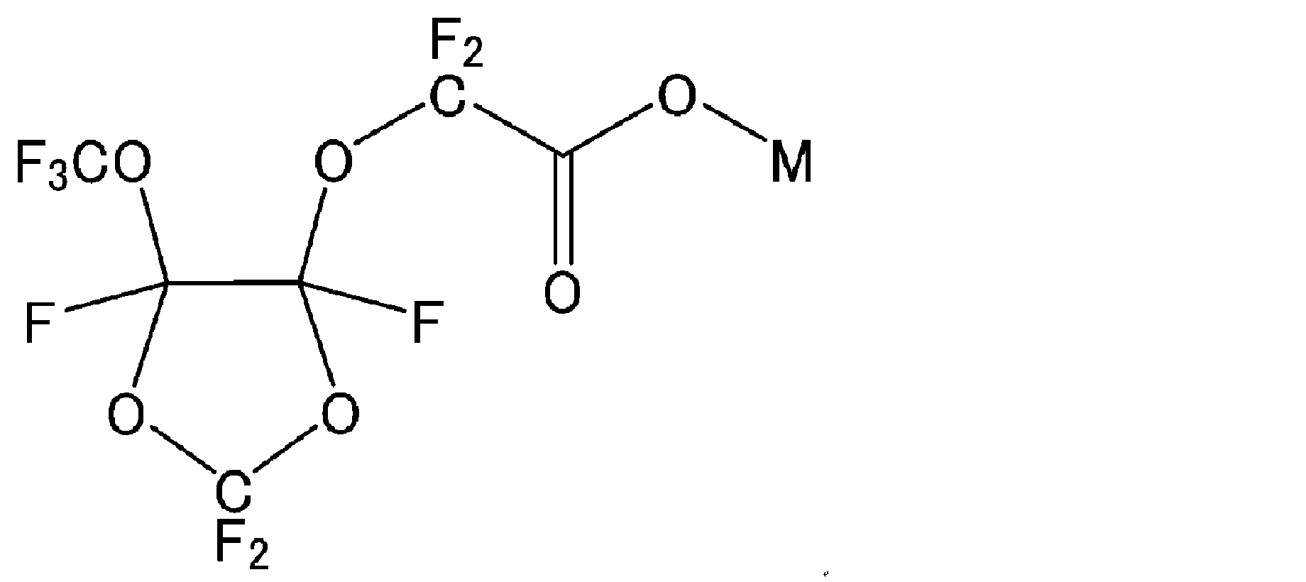
本開示のTFE系ポリマーは、上記式で表される含フッ素化合物のいずれをも実質的に含まないことが好ましい。
R1は、H又はC1-10の有機基であってよく、H又はC1-4の有機基であってよく、H又はC1-4のアルキル基であってよい。
上記式で表される含フッ素化合物のいずれをも実質的に含まないとは、当該含フッ素化合物の量が、上記TFE系ポリマーに対し25質量ppb以下であることを意味する。
上記含フッ素化合物の量は、20質量ppb以下であることが好ましく、15質量ppb以下であることがより好ましく、10質量ppb以下であることが更により好ましく、10質量ppb未満であることが更により好ましく、1質量ppb以下であることが更により好ましく、1質量ppb未満であることが更により好ましく、定量下限未満であることが特に好ましい。下限は特に限定されず、定量下限未満の量であってよい。
[Cn-1F2n-1COO-]M+
(式中、nは9~14の整数、好ましくは9~12の整数、M+はカチオンを表す。)で表される含フッ素化合物を実質的に含まないことも好ましい。これにより、ガス発生及び電気化学デバイス特性の劣化を一層抑制することができる。
上記式中のカチオンM+を構成するMは、上述したMと同様である。
上記式で表される含フッ素化合物を実質的に含まないとは、当該含フッ素化合物の量が、上記TFE系ポリマーに対し25質量ppb以下であることを意味する。
上記含フッ素化合物の量は、20質量ppb以下であることが好ましく、15質量ppb以下であることがより好ましく、10質量ppb以下であることが更により好ましく、10質量ppb未満であることが更により好ましく、1質量ppb以下であることが更により好ましく、1質量ppb未満であることが更により好ましく、定量下限未満であることが特に好ましい。下限は特に限定されず、定量下限未満の量であってよい。
上記吸熱ピーク温度は、300℃以上の温度に加熱した履歴がないTFE系ポリマーについて2℃/分の昇温速度で示差走査熱量測定〔DSC〕を行って得られた融解熱曲線における極小点に対応する温度である。1つの融解ピーク中に極小点が2つ以上ある場合は、それぞれを吸熱ピーク温度とする。
吸熱ピークが2つ以上ある場合は、そのいずれもが上記範囲内にあることが好ましい。
上記SSGは、ASTM D 4895に準拠して成形されたサンプルを用い、ASTM D 792に準拠した水置換法により測定する。
RR2500における押出圧力は、以下の方法により測定する。
TFE系ポリマー60gと押出助剤としての炭化水素油(商品名:アイソパーG(登録商標)、エクソンモービル社製)12.3gとをポリエチレン容器中で3分間混合する。室温(25±2℃)で押出機のシリンダーに上記混合物を充填し、シリンダーに挿入したピストンに0.47MPaの負荷をかけて1分間保持する。次にラム速度20mm/minでオリフィス(直径0.5mm、ランド長1.5mm、導入角30°)から押出する。オリフィスの断面積に対するシリンダーの断面積の比は2500である。押出操作の後半において、圧力が平衡状態になったときの荷重(N)をシリンダー断面積で除した値を押出圧力(MPa)とする。
上記平均二次粒子径は、JIS K 6891に準拠して測定する。
上記見掛密度は、JIS K 6892に準拠して測定する。
この製造方法によれば、上述したRR2500における押出圧力が100MPa以下であるTFE系ポリマーの水性分散液を容易に得ることができる。また、コアシェル構造を有するTFE系ポリマーを容易に得ることができる。
なかでも、フルオロ(アルキルビニルエーテル)及びフルオロオレフィンからなる群より選択される少なくとも1種が好ましく、PAVE、HFP及びCTFEからなる群より選択される少なくとも1種がより好ましく、PAVE及びCTFEからなる群より選択される少なくとも1種が更に好ましく、CTFEが更により好ましい。
工程(1a)における変性モノマーとして、PAVEとHFPとを併用することも好ましい。
PAVEとしては、パーフルオロ(プロピルビニルエーテル)〔PPVE〕が好ましい。
上記連鎖移動剤は、非過酸化有機化合物、水溶性有機過酸化物及び過硫酸塩の何れかを少なくとも1種有するものであればよい。
上記連鎖移動剤において、非過酸化有機化合物、水溶性有機過酸化物及び過硫酸塩は、それぞれ1種又は2種以上を用いることができる。
工程(1a)における変性モノマーとしてPAVE(及びHFP)を用いる場合、工程(2a)においては、連鎖移動剤としてメタノール(及び変性モノマーとしてHFP)を用いることが好ましい。
本明細書において、上記「転化率」は、目的とするTFE単位の量に相当するTFEの量のうち、重合開始時から重合途中のある時点までの間に重合に消費されたTFEの量が占める割合である。
上記アニオン性含フッ素界面活性剤は、上記水性媒体の0.02~0.3質量%とすることができる。
上記乳化重合は、重合開始剤が水性媒体100質量部あたり0.0001~0.02質量部となる量にて行うことが好ましい。
上記乳化重合は、通常、0.5~3.9MPaG、好ましくは、0.6~3MPaGにて行うことができる。
上記乳化重合は、また、重合初期、特にTFE系ポリマーの転化率が全体の15%以下の範囲まで0.5MPaG以下の圧力にて反応を行い、それ以後0.5MPaGを超える圧力に保つことによっても行うことができるし、芯部の形成途中で反応圧力を、例えば0.1MPaG以下に低下させ、再度TFEを供給し所定の圧力にて反応させることによっても行うことができる。
上記底面及び/又は側面に通気性のある容器としては、底面及び/又は側面に通気性を有するトレー(バット)が好ましく、底面及び/又は側面がメッシュで作製されたトレー(メッシュトレー)が更に好ましい。
上記メッシュは、織網とパンチングメタルのいずれかであることが好ましい。
上記メッシュの目開きは、2000μm以下(ASTM規格の10メッシュ以上)が好ましく、595μm以下(30メッシュ以上)がより好ましく、297μm以下(50メッシュ以上)が更に好ましく、177μm以下(80メッシュ以上)が更により好ましく、149μm以下(100メッシュ以上)が殊更に好ましく、74μm以下(200メッシュ以上)が特に好ましい。また、25μm以上(500メッシュ以下)が好ましい。
上記メッシュが織網である場合の織り方としては、例えば、平織、綾織、平畳織、綾畳織が挙げられる。
上記メッシュがパンチングメタルである場合の開孔率は、10%以上が好ましく、20%以上がより好ましく、30%以上が更に好ましい。また、95%以下が好ましい。
本開示のバインダーは、電極活物質、固体電解質等の電気化学デバイスの粉体成分と長時間混練しても凝集物が発生しにくく、上記粉体成分と均一に混合することができる。また、強度及び柔軟性に優れる合剤シートを得ることもできる。
本開示のバインダーは、また、水分を実質的に含まないので、電気化学デバイスセル内部のガス発生及び電気化学デバイス特性の劣化(例えば、高温保存時の容量の低下)を抑制することができる。
本開示のバインダーは、また、水や有機溶剤といった分散媒を多量に使用する必要がなく、組み合わせる電極活物質や固体電解質を広く選択することができ、生産工程上有利である。また、分散媒の使用による工程及びコストを削減することができる。
更に、本開示のバインダーは、活物質や電解質との結着力に優れるので、使用量を削減することができる。
上記TFE系ポリマーの含有量は、上記バインダーに対し、98.0質量%以上であることが好ましく、99.0質量%以上であることがより好ましく、99.5質量%以上であることが更に好ましく、99.9質量%以上であることが特に好ましく、99.95質量%以上であることが最も好ましい。
本開示のバインダーが上記TFE系ポリマーのみからなることも好ましい。
上記有機溶剤含有量は、3質量%以下であることが好ましく、1質量%以下であることがより好ましく、0.1質量%以下であることが更に好ましく、0.01質量%以下であることが更により好ましく、0.001質量%以下であることが特に好ましい。
電池としては、リチウムイオン電池等の二次電池等が挙げられる。
キャパシタとしては特に限定されないが、電気化学キャパシタであることが好ましい。電気化学キャパシタとしては、電気二重層キャパシタ、ハイブリッドキャパシタ、レドックスキャパシタ等が挙げられる。ハイブリッドキャパシタとしては、例えば、ナトリウムイオンキャパシタ、リチウムイオンキャパシタ、マグネシウムイオンキャパシタが挙げられる。これらの中でも特に電気二重層キャパシタが好ましい。
本開示のバインダーは、電池部材を作製するために用いられるものであってよい。
本開示のバインダーは、電極用バインダーとして特に好適に使用することができる。
本開示のバインダーは、また、固体二次電池の固体電解質層におけるバインダーとしても好適に使用することができる。
式:MaMn2-bM1 bO4
(式中、Mは、Li、Na及びKからなる群より選択される少なくとも1種の金属であり;0.9≦a;0≦b≦1.5;M1はFe、Co、Ni、Cu、Zn、Al、Sn、Cr、V、Ti、Mg、Ca、Sr、B、Ga、In、Si及びGeからなる群より選択される少なくとも1種の金属)で表されるアルカリ金属・マンガンスピネル複合酸化物(リチウム・マンガンスピネル複合酸化物等)、
式:MNi1-cM2 cO2
(式中、Mは、Li、Na及びKからなる群より選択される少なくとも1種の金属であり;0≦c≦0.5;M2はFe、Co、Mn、Cu、Zn、Al、Sn、Cr、V、Ti、Mg、Ca、Sr、B、Ga、In、Si及びGeからなる群より選択される少なくとも1種の金属)で表されるアルカリ金属・ニッケル複合酸化物(リチウム・ニッケル複合酸化物等)、又は、
式:MCo1-dM3 dO2
(式中、Mは、Li、Na及びKからなる群より選択される少なくとも1種の金属であり;0≦d≦0.5;M3はFe、Ni、Mn、Cu、Zn、Al、Sn、Cr、V、Ti、Mg、Ca、Sr、B、Ga、In、Si及びGeからなる群より選択される少なくとも1種の金属)で表されるアルカリ金属・コバルト複合酸化物(リチウム・コバルト複合酸化物等)が挙げられる。
上記において、Mは、好ましくは、Li、Na及びKからなる群より選択される1種の金属であり、より好ましくはLi又はNaであり、更に好ましくはLiである。
MNihCoiMnjM5 kO2 (3)
(式中、Mは、Li、Na及びKからなる群より選択される少なくとも1種の金属であり、M5はFe、Cu、Zn、Al、Sn、Cr、V、Ti、Mg、Ca、Sr、B、Ga、In、Si及びGeからなる群より選択される少なくとも1種を示し、(h+i+j+k)=1.0、0≦h≦1.0、0≦i≦1.0、0≦j≦1.5、0≦k≦0.2である。)
MeM4 f(PO4)g (4)
(式中、Mは、Li、Na及びKからなる群より選択される少なくとも1種の金属であり、M4はV、Ti、Cr、Mn、Fe、Co、Ni及びCuからなる群より選択される少なくとも1種を示し、0.5≦e≦3、1≦f≦2、1≦g≦3である。)で表される化合物が挙げられる。上記において、Mは、好ましくは、Li、Na及びKからなる群より選択される1種の金属であり、より好ましくはLi又はNaであり、更に好ましくはLiである。すなわち、上記アルカリ金属含有遷移金属リン酸化合物としては、リチウム含有遷移金属リン酸化合物が好ましい
LiyNi1-xMxO2 (5)
(式中、xは、0.01≦x≦0.7、yは、0.9≦y≦2.0であり、Mは金属原子(但しLi及びNiを除く)を表す)で表される正極活物質が好ましい。
上記タップ密度は、正極活物質粉体5~10gを10mlのガラス製メスシリンダーに入れ、ストローク約20mmで200回タップした時の粉体充填密度(タップ密度)g/cm3として求める。
上記平均一次粒子径は、走査電子顕微鏡(SEM)を用いた観察により測定される。具体的には、10000倍の倍率の写真で、水平方向の直線に対する一次粒子の左右の境界線による切片の最長の値を、任意の50個の一次粒子について求め、平均値をとることにより求められる。
上記BET比表面積は、表面積計(例えば、大倉理研社製全自動表面積測定装置)を用い、試料に対して窒素流通下150℃で30分間、予備乾燥を行なった後、大気圧に対する窒素の相対圧の値が0.3となるように正確に調整した窒素ヘリウム混合ガスを用い、ガス流動法による窒素吸着BET1点法によって測定した値で定義される。
上記導電助剤としては、公知の導電材を任意に用いることができる。具体例としては、銅、ニッケル等の金属材料、天然黒鉛、人造黒鉛等の黒鉛(グラファイト)、アセチレンブラック、ケッチェンブラック、チャンネルブラック、ファーネスブラック、ランプブラック、サーマルブラック等のカーボンブラック、ニードルコークス、カーボンナノチューブ、フラーレン、VGCF等の無定形炭素等の炭素材料等が挙げられる。なお、これらは、1種を単独で用いてもよく、2種以上を任意の組み合わせ及び比率で併用してもよい。
工程(a):粉体成分とバインダーとを混合して電極合剤を形成するステップと、
工程(b):電極合剤をカレンダリング又は押出成形してシートを製造するステップと
を含み、
工程(a)の混合は、
(a1)粉体成分とバインダーとを均質化して粉末にする工程と、
(a2)工程(a1)によって得られた粉末状の原料混合物を混合して電極合剤を調製する工程と
を含むことを特徴とする製造方法によっても、好適に製造することができる。
すなわち、このような(a1)においては、フィブリル化を抑制しながら、混合して均質化することが好ましい。
次いで行う工程である(a2)における混合は、30℃以上の温度で行うことで、フィブリル化を促進させることが好ましい。
一実施形態では、上記工程(b)のカレンダリング又は押し出しは、30℃から150℃の間、好ましくは35℃から120℃の間、より好ましくは40℃から100℃の間の温度で実行される。
具体的な混合方法としては、W型混合機、V型混合機、ドラム型混合機、リボン混合機、円錐スクリュー型混合機、1軸混練機、2軸混練機、ミックスマラー、撹拌ミキサー、プラネタリーミキサー、ヘンシェルミキサー、高速ミキサー等を用いて混合する方法が挙げられる。
工程(a1)では工程(a2)よりも弱い剪断力で行うことが好ましい。
また工程(a1)では工程(a2)よりも短い時間で行うことが望ましい。
水分含有量が1000ppm以下であることによって、電気化学デバイスの劣化を低減させるという点で好ましい。上記水分含有量は、500ppm以下であることが更に好ましい。
工程(b)は、(b1)前記工程(a)によって得られた電極合剤をバルク状に成形する工程と、(b2)バルク状の電極合剤をカレンダリング又は押出成形する工程を含むことが好ましい。
バルク状に成形する具体的な方法として、押出成形、プレス成形等が挙げられる。
また、「バルク状」とは、特に形状が特定されるものではなく、1つの塊状になっている状態であればよく、ロッド状、シート状、球状、キューブ状等の形態が含まれる。上記塊の大きさは、その断面の直径又は最小の一辺が10000μm以上であることが好ましい。より好ましくは20000μm以上である。
工程(c)の回数としては、2回以上10回以下が好ましく、3回以上9回以下がより好ましい。
具体的な圧延方法としては、例えば、2つあるいは複数のロールを回転させ、その間に圧延シートを通すことによって、より薄いシート状に加工する方法等が挙げられる。
また、工程(a)ないし、(b)、(c)、(d)において1軸延伸もしくは2軸延伸を行っても良い。
また、工程(d)での粗砕程度によってもシート強度を調整することができる。
なお、ここでいう圧延率とは、試料の圧延加工前の厚みに対する加工後の厚みの減少率を指す。圧延前の試料は、バルク状の原料組成物であっても、シート状の原料組成物であってもよい。試料の厚みとは、圧延時に荷重をかける方向の厚みを指す。
上記工程(c)~(d)は30℃以上で行うのが好ましく、60℃以上がより好ましい。また、150℃以下で行うのが好ましい。
なお、本明細書において、固体二次電池は、固体電解質を含む二次電池であればよく、電解質として固体電解質及び液体成分を含む半固体二次電池であってもよいし、電解質として固体電解質のみを含む全固体二次電池であってもよい。
上記固体二次電池は、正極、負極、並びに、当該正極及び当該負極の間に介在する固体電解質層を備えることが好ましい。
上記固体二次電池において、本開示のバインダーを電極層に用いてもよく、固体電解質層に用いてもよい。
本開示のバインダー及び固体電解質を含む固体二次電池用合剤(好ましくは合剤シート)、並びに、本開示のバインダー及び固体電解質を含む固体電解質層(好ましくは固体電解質層シート)も、本開示の好適な態様である。
TFE系ポリマー水性分散液を水で固形分濃度が0.15質量%になるまで希釈し、得られた希釈ラテックスの単位長さに対する550nmの投射光の透過率と、透過型電子顕微鏡写真により定方向径を測定して決定した数基準長さ平均一次粒子径とを測定して、検量線を作成した。この検量線を用いて、各試料の550nmの投射光の実測透過率から平均一次粒子径を決定した。
TFE系ポリマー水性分散液1gを、送風乾燥機中で150℃、60分の条件で乾燥し、水性分散液の質量(1g)に対する、加熱残分の質量の割合を百分率で表した値を採用する。
CTFE含有量は、TFE系ポリマー粉末をプレス成形することで薄膜ディスクを作製し、薄膜ディスクをFT-IR測定した赤外線吸光度から、957cm-1における吸光度/2360cm-1における吸光度の比に0.58を乗じて求めた。
PPVE含有量は、TFE系ポリマー粉末をプレス成形することで薄膜ディスクを作製し、薄膜ディスクをFT-IR測定した赤外線吸光度から、995cm-1における吸光度/935cm-1における吸光度の比に0.14を乗じて求めた。
HFP含有量は、TFE系ポリマー粉末をプレス成形することで薄膜ディスクを作製し、薄膜ディスクをFT-IR測定した赤外線吸光度から、982cm-1における吸光度/935cm-1における吸光度の比に0.3を乗じて求めた。
ASTM D4895 89に準拠して成形されたサンプルを用い、ASTM D 792に準拠した水置換法により測定した。
TFE系ポリマー粉末60gと押出助剤としての炭化水素油(商品名:アイソパーG(登録商標)、エクソンモービル社製)12.3gとをポリエチレン容器中で3分間混合した。室温(25±2℃)で押出機のシリンダーに上記混合物を充填し、シリンダーに挿入したピストンに0.47MPaの負荷をかけて1分間保持した。次にラム速度20mm/minでオリフィス (直径0.5mm、ランド長1.5mm、導入角30°) から押出した。オリフィスの断面積に対するシリンダーの断面積の比は2500であった。押出操作の後半において、圧力が平衡状態になったときの荷重(N)をシリンダー断面積で除した値を押出圧力(MPa)とした。
吸熱ピーク温度は、300℃以上の温度に加熱した履歴がないTFE系ポリマー粉末について示差走査熱量計〔DSC〕を用いて2℃/分の速度で昇温したときの融解熱曲線における極小点に対応する温度とした。
水分含有量(質量%)=[(加熱前のTFE系ポリマー粉末の質量(g))-(加熱後のTFE系ポリマー粉末の質量(g))]/(加熱前のTFE系ポリマー粉末の質量(g))×100
TFE系ポリマー粉末を1g秤量し、メタノールを10g(12.6ml)加え、60分間の超音波処理を行ない、抽出液を得た。得られた抽出液をLC/MS/MS測定した。抽出液中の含フッ素化合物について、液体クロマトグラフ質量分析計(Waters,LC-MS ACQUITY UPLC/TQD)を用いて測定を行った。測定機器構成とLC-MS測定条件を表1に示す。濃度既知の含フッ素化合物の水溶液を用いて、5水準以上の含有量の水溶液を作製し、それぞれの含有量の水溶液のLC/MS分析を行ない、含有量とその含有量に対するエリア面積と関係をプロットし、検量線を描いた。上記検量線を用いて、抽出液中の含フッ素化合物のLC/MSクロマトグラムのエリア面積を、含フッ素化合物の含有量に換算した。
なお、この測定方法における検出下限は10質量ppbである。
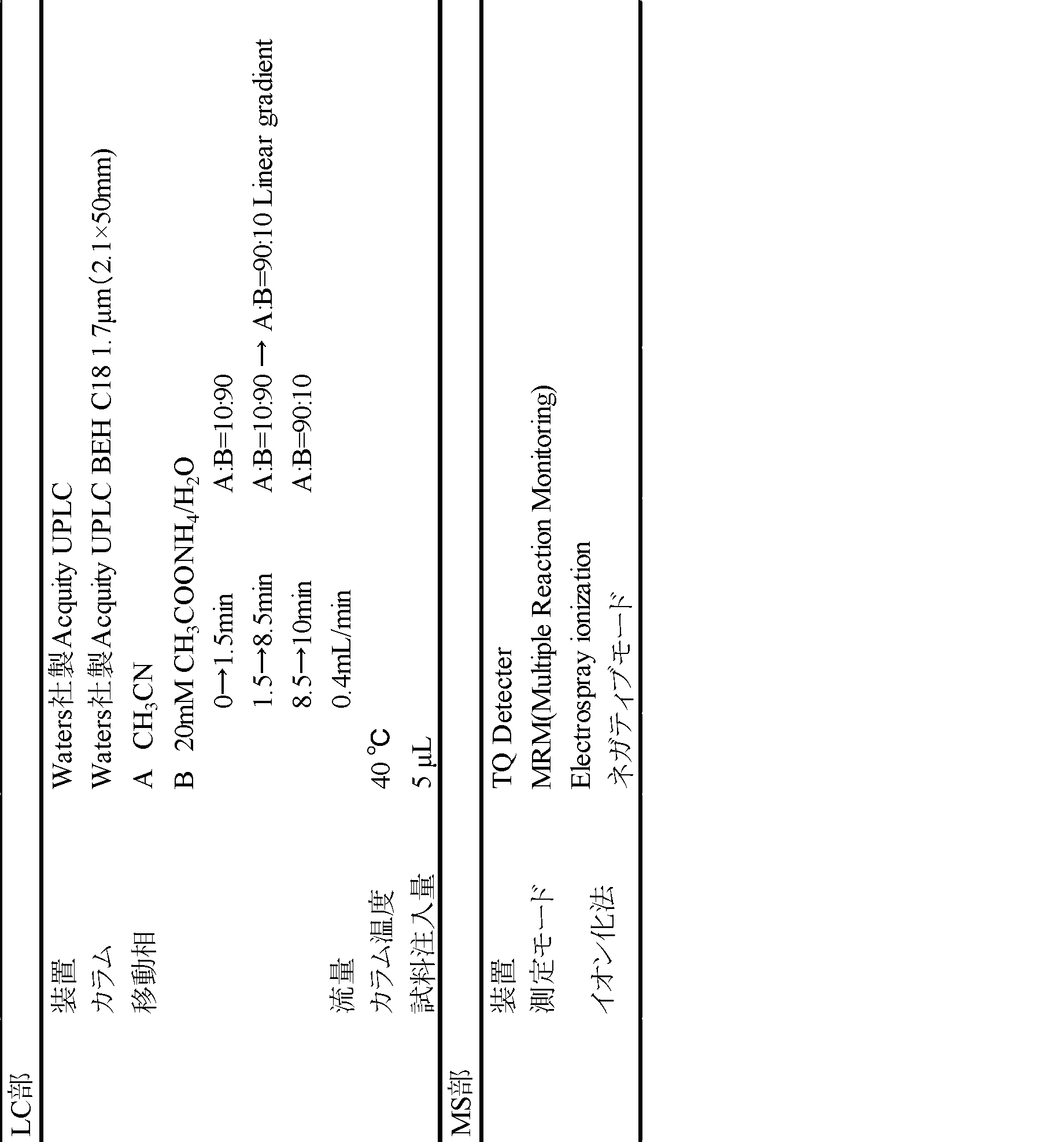
パーフルオロエーテルカルボン酸Bアンモニウム塩:富士フィルム和光純薬(株)製、Ammonium perfluoro(2-methyl-3-oxahexanoate)、構造式:CF3CF2CF2OCF(CF3)COONH4
親水性モノマー:Ammonium 2,3,3,3-tetrafluoro-2-[(1,1,2-trifluoro-2-propenyl)oxy]-Propanoate、構造式:CH2=CFCF2 OCF(CF3)COONH4
ステンレススチール製攪拌翼と温度調節用ジャケットを備えた内容量6リットルのステンレススチール製オートクレーブに、脱イオン水3580g、パラフィンワックス100g、及び白色固体A5.4gを仕込み、80℃に加温しながらオートクレーブ内を窒素ガスで置換して酸素を除いた。CTFE1.20gを加えた後、更にTFEを圧入して系内圧力を0.78MPaGとし、攪拌しながら系内温度を80℃に保った。次いで、水20gにジコハク酸パーオキサイド360mgを溶解した水溶液と、水20gに過硫酸アンモニウム10mgを溶解した水溶液をTFEで圧入し、重合反応を開始した。重合反応の進行に伴い系内圧力が低下するがTFEを追加して系内温度を80℃、系内圧力を0.78MPaGに維持した。重合開始からTFEが1530g消費された(転化率90%)時点で、CTFE4.2gをTFEで圧入した。重合はその後も継続し、TFEの重合量が重合開始から約1700gになった時点で撹拌及びTFEの供給を止め、直ちに系内のガスを放出して常圧とし、重合反応を終了した。水性分散液を取り出し、冷却後、パラフィンワックスを分離し、TFE系ポリマー水性分散液を得た。得られたTFE系ポリマー水性分散液の平均一次粒子径は241nm、固形分濃度は32.0質量%であった。上記で得られたTFE系ポリマーの粒子は、コアシェル構造を有する。
製造例1で得られたTFE系ポリマー水性分散液を固形分濃度13質量%にまで希釈して、撹拌機付きの容器内で激しく攪拌し凝固させた後、水と濾別し、TFE系ポリマー湿潤粉末を得た。
得られたTFE系ポリマー湿潤粉末をステンレス製のメッシュトレーに配置し(配置量:2.0g/cm2)、145℃の熱風循環式電気炉内でメッシュトレーを熱処理した。18時間後、メッシュトレーを取り出し、メッシュトレーを空冷させた後、TFE系ポリマー粉末1を得た。
得られたTFE系ポリマー粉末1のCTFE含有量は0.23質量%、SSGは2.170、押出圧力は59MPa、吸熱ピーク温度は336℃、水分含有量は0.001質量%、パーフルオロエーテルカルボン酸Aの含有量は10質量ppb未満であった。
ステンレススチール製攪拌翼と温度調節用ジャケットを備えた内容量6リットルのステンレススチール製オートクレーブに、脱イオン水3560g、パラフィンワックス100g、及び白色固体A1.5gを仕込み、70℃に加温しながらオートクレーブ内を窒素ガスで置換して酸素を除いた。PPVE3.0gを加えた後、更にTFEを圧入して系内圧力を0.78MPaGとし、攪拌しながら系内温度を70℃に保った。次いで、水20gにジコハク酸パーオキサイド326mgを溶解した水溶液と、水20gに過硫酸アンモニウム12mgを溶解した水溶液をTFEで圧入し、重合反応を開始した。重合反応の進行に伴い系内圧力が低下するがTFEを追加して系内温度を70℃、系内圧力を0.78MPaGに維持した。重合開始からTFEが170g消費された時点で、白色固体A2.2gをTFEで圧入した。重合開始からTFEが1530g消費された(転化率90%)時点で、メタノール0.28gをTFEで圧入した。重合はその後も継続し、TFEの重合量が重合開始から約1700gになった時点で撹拌及びTFEの供給を止め、直ちに系内のガスを放出して常圧とし、重合反応を終了した。水性分散液を取り出し、冷却後、パラフィンワックスを分離し、TFE系ポリマー水性分散液を得た。得られたTFE系ポリマー水性分散液の平均一次粒子径は243nm、固形分濃度は31.6質量%であった。上記で得られたTFE系ポリマーの粒子は、コアシェル構造を有する。
製造例2で得られたTFE系ポリマー水性分散液を固形分濃度13質量%にまで希釈して、撹拌機付きの容器内で激しく攪拌し凝固させた後、水と濾別し、TFE系ポリマー湿潤粉末を得た。
得られたTFE系ポリマー湿潤粉末をステンレス製のメッシュトレーに配置し(配置量:2.0g/cm2)、145℃の熱風循環式電気炉内でメッシュトレーを熱処理した。18時間後、メッシュトレーを取り出し、メッシュトレーを空冷させた後、TFE系ポリマー粉末2を得た。
得られたTFE系ポリマー粉末2のPPVE含有量は0.13質量%、SSGは2.166、押出圧力は56MPa、吸熱ピーク温度は333℃、水分含有量は0.000質量%、パーフルオロエーテルカルボン酸Aの含有量は10質量ppb未満であった。
ステンレススチール製攪拌翼と温度調節用ジャケットを備えた内容量6リットルのステンレススチール製オートクレーブに、脱イオン水3560g、パラフィンワックス100g、及び白色個体A0.9gを仕込み、70℃に加温しながらオートクレーブ内を窒素ガスで置換して酸素を除いた。PPVE0.67gとHFP0.37gを加えた後、更にTFEを圧入して系内圧力を0.78MPaGとし、攪拌しながら系内温度を70℃に保った。次いで、水20gにジコハク酸パーオキサイド322mgを溶解した水溶液と、水20gに過硫酸アンモニウム13mgを溶解した水溶液をTFEで圧入し、重合反応を開始した。重合反応の進行に伴い系内圧力が低下するがTFEを追加して系内温度を70℃、系内圧力を0.78MPaGに維持した。重合開始からTFEが160g消費された時点で、白色個体A4.5gをTFEで圧入した。重合開始からTFEが1440g消費された(転化率90%)時点で、HFP1.57gとメタノール0.5gをTFEで圧入した。重合はその後も継続し、TFEの重合量が重合開始から1600gになった時点で撹拌及びTFEの供給を止め、直ちに系内のガスを放出して常圧とし、重合反応を終了した。水性分散液を取り出し、冷却後、パラフィンワックスを分離し、TFE系ポリマー水性分散液を得た。得られたTFE系ポリマー水性分散液の平均一次粒子径は249nm、固形分濃度は30.7質量%であった。上記で得られたTFE系ポリマーの粒子は、コアシェル構造を有する。
製造例3で得られたTFE系ポリマー水性分散液を固形分濃度13質量%にまで希釈して、撹拌機付きの容器内で激しく攪拌し凝固させた後、水と濾別し、TFE系ポリマー湿潤粉末を得た。
得られたTFE系ポリマー湿潤粉末をステンレス製のメッシュトレーに配置し(配置量:2.0g/cm2 )、145℃の熱風循環式電気炉内でメッシュトレーを熱処理した。18時間後、メッシュトレーを取り出し、メッシュトレーを空冷させた後、TFE系ポリマー粉末3を得た。
得られたTFE系ポリマー粉末3のPPVE含有量は0.03質量%、HFP含有量は0.05質量%、SSGは2.176、押出圧力は49MPa、吸熱ピーク温度は336℃、水分含有量は0.001質量%、パーフルオロエーテルカルボン酸Aの含有量は10質量ppb未満であった。
白色固体A5.4gをパーフルオロエーテルカルボン酸Bアンモニウム塩16g、親水性モノマー30mgに変更する以外は、製造例1と同様にしてTFE系ポリマー水性分散液を得た。得られたTFE系ポリマー水性分散液の平均一次粒子径は245nm、固形分濃度は31.8質量%であった。上記で得られたTFE系ポリマーの粒子は、コアシェル構造を有する。
製造例4で得られたTFE系ポリマー水性分散液を固形分濃度13質量%にまで希釈して、撹拌機付きの容器内で激しく攪拌し凝固させた後、水と濾別し、TFE系ポリマー湿潤粉末を得た。
得られたTFE系ポリマー湿潤粉末をステンレス製の平板トレー(底面及び側面に通気性のないトレー)に配置し、145℃の熱風循環式電気炉内でメッシュトレーを熱処理した。18時間後、メッシュトレーを取り出し、メッシュトレーを空冷させた後、TFE系ポリマー粉末4を得た。
得られたTFE系ポリマー粉末4のCTFE含有量は0.23質量%、SSGは2.172、押出圧力は60MPa、吸熱ピーク温度は336℃、水分含有量は0.018質量%、パーフルオロエーテルカルボン酸Bの含有量は180質量ppbであった。
ステンレススチール製攪拌翼と温度調節用ジャケットを備えた内容量6リットルのステンレススチール製オートクレーブに、脱イオン水3480g、パラフィンワックス100g、及び白色固体A5.3gを仕込み、70℃に加温しながらオートクレーブ内を窒素ガスで置換して酸素を除いた。TFEを圧入して系内圧力を0.78MPaGとし、攪拌しながら系内温度を70℃に保った。次いで、水20gに過硫酸アンモニウム15.0mgを溶解した水溶液をTFEで圧入し、重合反応を開始した。重合反応の進行に伴い系内圧力が低下するがTFEを追加して系内温度を70℃、系内圧力を0.78MPaGに維持した。
重合開始からTFEが400g消費された時点で、ラジカル捕捉剤としてヒドロキノン18.0mgを水20gに溶解した水溶液をTFEで圧入した。重合はその後も継続し、TFEの重合量が重合開始から約1200gになった時点で撹拌及びTFEの供給を止め、直ちに系内のガスを放出して常圧とし、重合反応を終了した。水性分散液を取り出し、冷却後、パラフィンワックスを分離し、TFE系ポリマー水性分散液を得た。得られたTFE系ポリマー水性分散液の平均一次粒子径は310nm、固形分濃度は25.3質量%であった。
製造例5で得られたTFE系ポリマー水性分散液を固形分濃度13質量%まで希釈し、撹拌機付きの容器内で激しく攪拌し凝固させた後、水と濾別し、TFE系ポリマー湿潤粉末を得た。
得られたTFE系ポリマー湿潤粉末をステンレス製のメッシュトレーに配置し(配置量:2.0g/cm2)、180℃の熱風循環式電気炉内でメッシュトレーを熱処理した。20時間後、メッシュトレーを取り出し、メッシュトレーを空冷させた後、TFE系ポリマー粉末5を得た。
得られたTFE系ポリマー粉末5のSSGは2.156、吸熱ピーク温度は344℃、水分含有量は0.000質量%、パーフルオロエーテルカルボン酸Aの含有量は10質量ppb未満であった。押出圧力は、上記条件では押出できず、測定不可であった。よって、押出圧力が100MPaを超えていることは明らかである。
作製例1で得られたTFE系ポリマー湿潤粉末を平板トレーに配置し、145℃の熱風循環式電気炉内で平板トレーを熱処理した。5時間後、平板トレーを取り出し、平板トレーを空冷させた後、TFE系ポリマー粉末6を得た。
得られたTFE系ポリマー粉末6のCTFE含有量は0.23質量%、SSGは2.170、押出圧力は58MPa、吸熱ピーク温度は336℃、水分含有量は0.137質量%であった。
下記の手順で実施例1~2、A1~2及び比較例1~2の合剤シート作製とシート評価を行った。
<正極合剤シートの作製>
活物質と導電助剤を秤量し、V型混合機に材料を投入し、37rpmで10分間混合し活物質と導電助剤からなる混合物を得た。その後、混合物に秤量したバインダー(TFE系ポリマー粉末)を投入し、5℃の恒温槽にて十分に冷却させた。活物質、導電助剤とバインダーからなる混合物をヘンシェルミキサーに投入し、1000rpmで3分間処理することで混合物の均質化を行った。
その後、混合物を50℃の恒温槽にて十分に昇温させた後に、加圧型ニーダー(D1-5:日本スピンドル社製)にて5分間処理(32rpm、ヒーター50℃,圧力0.5MPa)することでフィブリル化を促進し、凝集性のあるバルク状の電極合剤を得た。その後、再粉砕するためにバルク状の電極合剤をヘンシェルミキサーに投入し、300rpmで1分間処理することで電極合剤を得た。
平行に配置された金属ロール(温度:80℃、回転速度:1m/min)に電極合剤を投入し、圧延することで電極合剤シートを得た。再度、得られた圧延シートを2つに折りたたむことにより粗砕して、金属ロール(温度:80℃、回転速度:1m/min)に電極合剤を投入し、圧延することでより強度のある電極合剤シートを得た。
その後、ロールプレス機に電極合剤シートを投入し、ギャップを調整した。最終的な正極合剤層の厚みは90μmになるように調整した。
表2に材料種と組成を示す。

平行に配置された金属ロールに投入する前の電極合剤を用いて、目開き0.18mm(JIS-Z8801)のふるいにより30秒ふるいがけを行い、メッシュの上に凝集物が残った場合を×、全て通過した場合を○とした。結果を表3に示す。
上記正極合剤シートを切り出し4mm幅の短冊状の試験片を作製した。引張試験機(島津製作所社製AGS-100NX)を使用して、100mm/分の条件下にて測定した。チャック間距離は30mmとした。破断するまで変位を与え、測定した結果の最大応力を各サンプルの強度とした。N=8で試験を行い、平均値を求めた。比較例1を100%として比較した。またその際の変動係数を算出し、ばらつきを評価した。結果を表3に示す。
作製した電極合剤シートを幅4cm、長さ10cmに切り取り試験片とした。次に、これらの試験片をΦ10mmの丸棒に巻き付けた後、目視で試験片を確認し、傷や割れといった破損の有無を確認した。破損が見られない場合、更に細いΦ5mmの丸棒で試験を行い、破損を確認した。やはり、破損が見られない場合、更に細いΦ2mmの丸棒で試験を行い、破損を確認した。その結果をA~Dで分類した。結果を表3に示す。
A:Φ2mm棒で破損なし
B:Φ2mm棒で破損あり
C:Φ5mm棒で破損あり
D:Φ10mm棒で破損あり
上記正極合剤シートを、以下のようにして20μmのアルミ箔と接着させた。
接着剤には、N-メチルピロリドン(NMP)にポリビニデンフルオライド(PVDF)を溶解させ、カーボンブラックを80:20で分散させたスラリーを用いた。アルミ箔に上述した接着剤を塗布し、ホットプレートにて120℃、15分間乾燥させ、接着層つき集電体を形成した。
その後、正極合剤シートを接着層つき集電体の上に置き、100℃に加熱したロールプレス機にて正極合剤シートと集電体の貼り合わせを行い、所望のサイズに切り出し、タブ付を行って正極とした。
炭素質材料(グラファイト)98質量部に、増粘剤及びバインダーとして、カルボキシメチルセルロースナトリウムの水性ディスパージョン(カルボキシメチルセルロースナトリウムの濃度1質量%)1質量部及びスチレン-ブタジエンゴムの水性ディスパージョン(スチレン-ブタジエンゴムの濃度50質量%)1質量部を加え、ディスパーザーで混合してスラリー化した。得られたスラリーを厚さ10μmの銅箔に塗布して乾燥し、プレス機で圧延したものを所望のサイズに切り出し、タブ付を行って負極とした。
有機溶媒として、エチレンカーボネート(EC)及びエチルメチルカーボネート(EMC)の混合溶媒(EC:EMC=30:70(体積比))をサンプル瓶に量り取り、ここにフルオロエチレンカーボネート(FEC)とビニレンカーボネート(VC)を1質量%ずつ溶解させて混合液を調製した。この混合液に、電解液中の濃度が1.1モル/Lとなるように、LiPF6塩を23℃で混合することにより、非水電解液を得た。
上記の正極を厚さ20μmの微孔性ポリエチレンフィルム(セパレータ)を介して負極と対向させ、上記で得られた非水電解液を注入し、上記非水電解液がセパレータ等に充分に浸透した後、封止し予備充電、エージングを行い、リチウムイオン二次電池を作製した。
上記で製造したリチウムイオン二次電池を、25℃において、0.33Cに相当する電流で4.3Vまで定電流-定電圧充電(以下、CC/CV充電と表記する。)(0.1Cカット)した後、0.33Cの定電流で3Vまで放電し、これを1サイクルとして、3サイクル目の放電容量から初期放電容量を求めた。
初期放電容量の評価が終了した電池を再度、25℃において4.3VまでCC/CV充電(0.1Cカット)し、アルキメデス法により電池の体積を求めた。電池の体積を求めた後、60℃、30日間の条件で高温保存を行った。高温保存終了後、十分に冷却した後25℃において電池の体積を求め、保存試験前後の電池の体積差からガス発生量を求めた。比較例1のガス発生量を100として、ガス発生量を比較した。
ガス発生量を求めた後、25℃において0.33Cで3Vまで放電を行い、残存容量を求めた。
初期放電容量に対する高温保存後の残存容量の割合を求め、これを残存容量率(%)とした。
(残存容量)/(初期放電容量)×100=残存容量率(%)
結果を表3に示す。

下記の手順で実施例3~4、B1~2及び比較例3~4の合剤シート作製とシート評価を行った。作製及び評価はアルゴン雰囲気下にて行われた。
活物質と導電助剤を秤量し、V型混合機に材料を投入し、37rpmで10分間混合し活物質と導電助剤からなる混合物を得た。その後、混合物に秤量したバインダー(TFE系ポリマー粉末)と固体電解質を投入し、5℃の恒温槽にて十分に冷却させた。活物質、導電助剤、バインダー、固体電解質とからなる混合物をヘンシェルミキサーに投入し、300rpmで2分間処理することで混合物の均質化を行った。
その後、混合物を40℃の恒温槽にて十分に昇温させた後に、ヘンシェルミキサーにて1000rpmで3分間処理することでフィブリル化を促進し、電極合剤を得た。
平行に配置された金属ロール(温度:80℃、回転速度:1m/min)に電極合剤を投入し、圧延することで電極合剤シートを得た。再度、得られた圧延シートを2つに折りたたむことにより粗砕して、金属ロール(温度:80℃、回転速度:1m/min)に電極合剤を投入し、圧延することでより強度のある電極合剤シートを得た。
その後、ロールプレス機に電極合剤シートを投入し、ギャップを調整した。最終的な正極合剤層の厚みは100μmになるように調整した。
表4に材料種と組成を示す。

上記正極合剤シートを切り出し4mm幅の短冊状の試験片を作製した。引張試験機(島津製作所社製AGS-100NX)を使用して、100mm/分の条件下にて測定した。チャック間距離は30mmとした。破断するまで変位を与え、測定した結果の最大応力を各サンプルの強度とした。N=3で試験を行い、平均値を求めた。比較例3を100%として比較した。結果を表5に示す。
作製した電極合剤シートを幅4cm、長さ10cmに切り取り試験片とした。次に、これらの試験片をΦ10mmの丸棒に巻き付けた後、目視で試験片を確認し、傷や割れといった破損の有無を確認した。破損が見られない場合、更に細いΦ5mmの丸棒で試験を行い、破損を確認した。やはり、破損が見られない場合、更に細いΦ2mmの丸棒で試験を行い、破損を確認した。その結果をA~Dで分類した。結果を表5に示す。
A:Φ2mm棒で破損なし
B:Φ2mm棒で破損あり
C:Φ5mm棒で破損あり
D:Φ10mm棒で破損あり
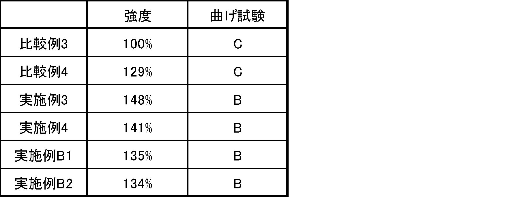
下記の手順で実施例5~6、C1~2及び比較例5~6の合剤シート作製とシート評価を行った。作製及び評価はアルゴン雰囲気下にて行われた。
秤量したバインダー(TFE系ポリマー粉末)を5℃の恒温槽にて十分に冷却させた後、ヘンシェルミキサーに投入し、300rpmで2分間処理することで粉砕処理を行った。
粉砕した結着剤と固体電解質をそれぞれ秤量し、5℃の恒温槽にて十分に冷却させた。ヘンシェルミキサーに投入し、300rpmで1分間処理することで混合物の均質化を行った。
その後、混合物を40℃の恒温槽にて十分に昇温させた後に、ヘンシェルミキサーにて1000rpmで1分間処理することでフィブリル化を促進し、電解質合剤を得た。
平行に配置された金属ロール(温度:80℃、回転速度:1m/min)に電極合剤を投入し、圧延することで電解質合剤シートを得た。再度、得られた圧延シートを2つに折りたたむことにより粗砕して、金属ロール(温度:80℃、回転速度:1m/min)に電解質合剤を投入し、圧延することでより強度のある電解質合剤シートを得た。
その後、ロールプレス機に電解質合剤シートを投入し、ギャップを調整した。最終的な電解質合剤シートの厚みは110μmになるように調整した。
表6に材料種と組成を示す。
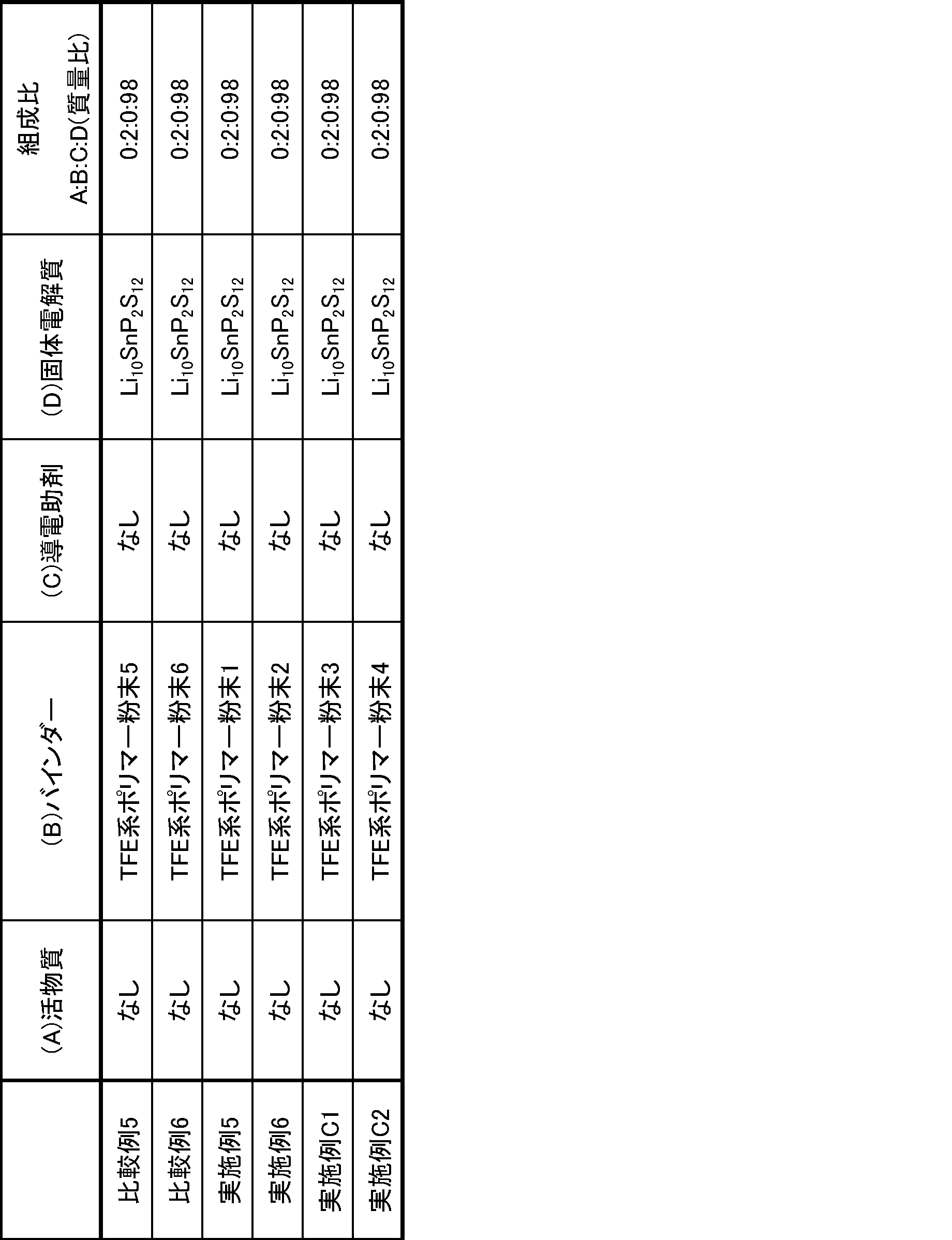
上記固体電解質合剤シートを切り出し4mm幅の短冊状の試験片を作製した。引張試験機(島津製作所社製AGS-100NX)を使用して、100mm/分の条件下にて測定した。チャック間距離は30mmとした。破断するまで変位を与え、測定した結果の最大応力を各サンプルの強度とした。N=3で試験を行い、平均値を求めた。比較例5を100%として比較した。結果を表7に示す。
作製した固体電解質合剤シートを幅4cm、長さ10cmに切り取り試験片とした。次に、これらの試験片をΦ10mmの丸棒に巻き付けた後、目視で試験片を確認し、傷や割れといった破損の有無を確認した。破損が見られない場合、更に細いΦ5mmの丸棒で試験を行い、破損を確認した。やはり、破損が見られない場合、更に細いΦ2mmの丸棒で試験を行い、破損を確認した。その結果をA~Dで分類した。結果を表7に示す。
A:Φ2mm棒で破損なし
B:Φ2mm棒で破損あり
C:Φ5mm棒で破損あり
D:Φ10mm棒で破損あり
固体電解質合剤シートを適当な大きさに切り出し、両面に金を蒸着した。その後、パンチでΦ10mmの円形に打ち抜いた固体電解質合剤シートを圧力セルに納め、セルのネジを8Nで締め、セルの上下から電極をとった。用いた圧力セルの断面の概略図を図1に示す。
この試料について、東陽テクニカ製インピーダンス装置を用い、25℃、AC振幅変調10mV、周波数5×10⁶~0.1Hzの条件でイオン伝導度を測定した。
結果を表7に示す。
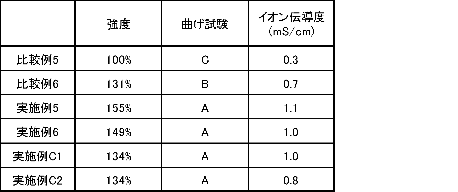
2:ナット
3:絶縁シート
4:固体電解質合剤シート
5:金蒸着
6:上部電極
7:下部電極
Claims (19)
- 電気化学デバイス用バインダーに使用されるテトラフルオロエチレン系ポリマーであって、
リダクションレシオ2500における押出圧力が100MPa以下であり、
水分を実質的に含まないテトラフルオロエチレン系ポリマー。 - 実質的にテトラフルオロエチレン系ポリマーのみからなる電気化学デバイス用バインダーであって、
前記テトラフルオロエチレン系ポリマーは、
リダクションレシオ2500における押出圧力が100MPa以下であり、
水分を実質的に含まない電気化学デバイス用バインダー。 - 前記テトラフルオロエチレン系ポリマーのリダクションレシオ2500における押出圧力が45MPa以上、65MPa以下である請求項2記載の電気化学デバイス用バインダー。
- 前記テトラフルオロエチレン系ポリマーは、標準比重が2.200以下である請求項2又は3記載の電気化学デバイス用バインダー。
- 前記テトラフルオロエチレン系ポリマーは、吸熱ピーク温度が320℃以上である請求項2~4のいずれかに記載の電気化学デバイス用バインダー。
- 前記テトラフルオロエチレン系ポリマーがポリテトラフルオロエチレンである請求項2~5のいずれかに記載の電気化学デバイス用バインダー。
- 前記テトラフルオロエチレン系ポリマーは、テトラフルオロエチレン単位、及び、テトラフルオロエチレンと共重合可能な変性モノマーに基づく変性モノマー単位を含む請求項2~6のいずれかに記載の電気化学デバイス用バインダー。
- 前記テトラフルオロエチレン系ポリマーにおいて、前記変性モノマー単位の含有量が10質量%以下である請求項7記載の電気化学デバイス用バインダー。
- 前記テトラフルオロエチレン系ポリマーにおいて、前記変性モノマー単位の含有量が0.25質量%以下である請求項8記載の電気化学デバイス用バインダー。
- 前記変性モノマーは、下記一般式(I)で表される化合物である請求項8又は9記載の電気化学デバイス用バインダー。
CX1X2=CX3X4 (I)
(式中、X1~X3は、それぞれ独立して、H又はFである。X4は、F、Cl、CF3、Rf又はO-Rfである。Rfは、パーフルオロ有機基である。) - 前記変性モノマーが、クロロトリフルオロエチレン及びヘキサフルオロプロピレンからなる群より選択される少なくとも1種である請求項8~10のいずれかに記載の電気化学デバイス用バインダー。
- 前記テトラフルオロエチレン系ポリマーは、粉末である請求項2~11のいずれかに記載の電気化学デバイス用バインダー。
- 前記テトラフルオロエチレン系ポリマーは、分子量1000以下の含フッ素化合物を実質的に含まない請求項2~12のいずれかに記載の電気化学デバイス用バインダー。
- 電池用バインダー又はキャパシタ用バインダーである請求項2~13のいずれかに記載の電気化学デバイス用バインダー。
- 二次電池用である請求項2~14のいずれかに記載の電気化学デバイス用バインダー。
- 請求項1記載のテトラフルオロエチレン系ポリマー、又は、請求項2~15のいずれかに記載の電気化学デバイス用バインダーと、電極活物質とを含む電極合剤。
- シートである請求項16記載の電極合剤。
- 請求項1記載のテトラフルオロエチレン系ポリマー、又は、請求項2~15のいずれかに記載の電気化学デバイス用バインダーと、電極活物質と、集電体とを含む電極。
- 請求項18記載の電極を備える二次電池。
Priority Applications (4)
| Application Number | Priority Date | Filing Date | Title |
|---|---|---|---|
| KR1020257025885A KR20250127336A (ko) | 2023-01-18 | 2024-01-18 | 테트라플루오로에틸렌계 폴리머, 전기 화학 디바이스용 바인더, 전극 합제, 전극, 및 이차 전지 |
| CN202480008043.6A CN120548624A (zh) | 2023-01-18 | 2024-01-18 | 四氟乙烯系聚合物、电化学器件用粘结剂、电极合剂、电极和二次电池 |
| EP24744728.7A EP4462518A4 (en) | 2023-01-18 | 2024-01-18 | Tetrafluoroethylene-based polymer, binder for electrochemical devices, electrode mix, electrode, and secondary battery |
| US19/270,910 US20250340683A1 (en) | 2023-01-18 | 2025-07-16 | Tetrafluoroethylene-based polymer, binder for electrochemical devices, electrode mixture, electrode, and secondary battery |
Applications Claiming Priority (2)
| Application Number | Priority Date | Filing Date | Title |
|---|---|---|---|
| JP2023005934 | 2023-01-18 | ||
| JP2023-005934 | 2023-01-18 |
Related Child Applications (1)
| Application Number | Title | Priority Date | Filing Date |
|---|---|---|---|
| US19/270,910 Continuation US20250340683A1 (en) | 2023-01-18 | 2025-07-16 | Tetrafluoroethylene-based polymer, binder for electrochemical devices, electrode mixture, electrode, and secondary battery |
Publications (1)
| Publication Number | Publication Date |
|---|---|
| WO2024154808A1 true WO2024154808A1 (ja) | 2024-07-25 |
Family
ID=91956067
Family Applications (1)
| Application Number | Title | Priority Date | Filing Date |
|---|---|---|---|
| PCT/JP2024/001353 Ceased WO2024154808A1 (ja) | 2023-01-18 | 2024-01-18 | テトラフルオロエチレン系ポリマー、電気化学デバイス用バインダー、電極合剤、電極、及び、二次電池 |
Country Status (6)
| Country | Link |
|---|---|
| US (1) | US20250340683A1 (ja) |
| EP (1) | EP4462518A4 (ja) |
| JP (2) | JP7834119B2 (ja) |
| KR (1) | KR20250127336A (ja) |
| CN (1) | CN120548624A (ja) |
| WO (1) | WO2024154808A1 (ja) |
Families Citing this family (1)
| Publication number | Priority date | Publication date | Assignee | Title |
|---|---|---|---|---|
| US12588463B2 (en) * | 2023-04-21 | 2026-03-24 | STATS ChipPAC Pte. Ltd. | Semiconductor device and methods of making and using an enhanced carrier to reduce electrostatic discharge |
Citations (11)
| Publication number | Priority date | Publication date | Assignee | Title |
|---|---|---|---|---|
| JP2005527652A (ja) | 2002-01-04 | 2005-09-15 | イー・アイ・デュポン・ドウ・ヌムール・アンド・カンパニー | 濃縮フルオロポリマー分散液 |
| JP2012119297A (ja) * | 2010-06-30 | 2012-06-21 | Daikin Ind Ltd | 電極用バインダー組成物 |
| JP2012117031A (ja) * | 2010-06-30 | 2012-06-21 | Daikin Industries Ltd | 含フッ素重合体のオルガノゾル組成物 |
| WO2012133655A1 (ja) * | 2011-03-31 | 2012-10-04 | ダイキン工業株式会社 | フルオロポリマー水性分散液 |
| JP2017517862A (ja) | 2014-04-18 | 2017-06-29 | マックスウェル テクノロジーズ インコーポレイテッド | エネルギー貯蔵装置の乾式電極とその製造方法 |
| WO2021045228A1 (ja) | 2019-09-05 | 2021-03-11 | ダイキン工業株式会社 | ポリテトラフルオロエチレン水性分散液 |
| WO2022018954A1 (ja) * | 2020-07-20 | 2022-01-27 | パナソニックIpマネジメント株式会社 | 電池用正極及び電池 |
| WO2022050251A1 (ja) * | 2020-09-01 | 2022-03-10 | ダイキン工業株式会社 | 二次電池用電極合剤、二次電池用電極合剤シート及びその製造方法並びに二次電池 |
| WO2022114860A1 (ko) * | 2020-11-30 | 2022-06-02 | 주식회사 엘지에너지솔루션 | 이차전지용 양극 활물질, 이의 제조방법, 이를 포함하는 프리스탠딩 필름, 건식 양극 및 건식양극을 포함하는 이차전지 |
| WO2022138939A1 (ja) | 2020-12-25 | 2022-06-30 | ダイキン工業株式会社 | 非水系電解液を使用する二次電池用電極の製造方法及び非水系電解液を使用する二次電池電極用結着剤 |
| JP2022546129A (ja) | 2019-09-03 | 2022-11-02 | ソルヴェイ(ソシエテ アノニム) | 硫化物ベースの固体複合電解質膜 |
Family Cites Families (7)
| Publication number | Priority date | Publication date | Assignee | Title |
|---|---|---|---|---|
| JP3616784B2 (ja) * | 1995-09-22 | 2005-02-02 | 三井・デュポンフロロケミカル株式会社 | 変性ポリテトラフルオロエチレンファインパウダーの製造方法 |
| EP4063403A4 (en) * | 2019-11-19 | 2024-01-24 | Daikin Industries, Ltd. | PROCESS FOR MANUFACTURING FLUOROPOLYMER |
| JP7668475B2 (ja) | 2020-03-11 | 2025-04-25 | パナソニックIpマネジメント株式会社 | 電極の製造方法および電極合材 |
| EP4120383A4 (en) | 2020-03-11 | 2024-07-31 | Panasonic Intellectual Property Management Co., Ltd. | ELECTRODE FOR SECONDARY BATTERY AND PRODUCTION METHOD THEREFOR |
| JPWO2021192541A1 (ja) | 2020-03-24 | 2021-09-30 | ||
| WO2022138942A1 (ja) | 2020-12-25 | 2022-06-30 | ダイキン工業株式会社 | 固体二次電池用シートの製造方法及び固体二次電池用結着剤 |
| KR20220100240A (ko) * | 2021-01-08 | 2022-07-15 | 현대자동차주식회사 | 건식 바인더 및 이를 포함하는 리튬 이차전지용 전극과 그 제조방법 |
-
2024
- 2024-01-18 JP JP2024006318A patent/JP7834119B2/ja active Active
- 2024-01-18 CN CN202480008043.6A patent/CN120548624A/zh active Pending
- 2024-01-18 EP EP24744728.7A patent/EP4462518A4/en active Pending
- 2024-01-18 WO PCT/JP2024/001353 patent/WO2024154808A1/ja not_active Ceased
- 2024-01-18 KR KR1020257025885A patent/KR20250127336A/ko active Pending
-
2025
- 2025-02-05 JP JP2025017620A patent/JP2025065309A/ja active Pending
- 2025-07-16 US US19/270,910 patent/US20250340683A1/en active Pending
Patent Citations (11)
| Publication number | Priority date | Publication date | Assignee | Title |
|---|---|---|---|---|
| JP2005527652A (ja) | 2002-01-04 | 2005-09-15 | イー・アイ・デュポン・ドウ・ヌムール・アンド・カンパニー | 濃縮フルオロポリマー分散液 |
| JP2012119297A (ja) * | 2010-06-30 | 2012-06-21 | Daikin Ind Ltd | 電極用バインダー組成物 |
| JP2012117031A (ja) * | 2010-06-30 | 2012-06-21 | Daikin Industries Ltd | 含フッ素重合体のオルガノゾル組成物 |
| WO2012133655A1 (ja) * | 2011-03-31 | 2012-10-04 | ダイキン工業株式会社 | フルオロポリマー水性分散液 |
| JP2017517862A (ja) | 2014-04-18 | 2017-06-29 | マックスウェル テクノロジーズ インコーポレイテッド | エネルギー貯蔵装置の乾式電極とその製造方法 |
| JP2022546129A (ja) | 2019-09-03 | 2022-11-02 | ソルヴェイ(ソシエテ アノニム) | 硫化物ベースの固体複合電解質膜 |
| WO2021045228A1 (ja) | 2019-09-05 | 2021-03-11 | ダイキン工業株式会社 | ポリテトラフルオロエチレン水性分散液 |
| WO2022018954A1 (ja) * | 2020-07-20 | 2022-01-27 | パナソニックIpマネジメント株式会社 | 電池用正極及び電池 |
| WO2022050251A1 (ja) * | 2020-09-01 | 2022-03-10 | ダイキン工業株式会社 | 二次電池用電極合剤、二次電池用電極合剤シート及びその製造方法並びに二次電池 |
| WO2022114860A1 (ko) * | 2020-11-30 | 2022-06-02 | 주식회사 엘지에너지솔루션 | 이차전지용 양극 활물질, 이의 제조방법, 이를 포함하는 프리스탠딩 필름, 건식 양극 및 건식양극을 포함하는 이차전지 |
| WO2022138939A1 (ja) | 2020-12-25 | 2022-06-30 | ダイキン工業株式会社 | 非水系電解液を使用する二次電池用電極の製造方法及び非水系電解液を使用する二次電池電極用結着剤 |
Non-Patent Citations (1)
| Title |
|---|
| See also references of EP4462518A4 |
Also Published As
| Publication number | Publication date |
|---|---|
| JP2025065309A (ja) | 2025-04-17 |
| EP4462518A4 (en) | 2026-04-22 |
| JP7834119B2 (ja) | 2026-03-23 |
| US20250340683A1 (en) | 2025-11-06 |
| KR20250127336A (ko) | 2025-08-26 |
| EP4462518A1 (en) | 2024-11-13 |
| CN120548624A (zh) | 2025-08-26 |
| JP2024102034A (ja) | 2024-07-30 |
Similar Documents
| Publication | Publication Date | Title |
|---|---|---|
| US20250340683A1 (en) | Tetrafluoroethylene-based polymer, binder for electrochemical devices, electrode mixture, electrode, and secondary battery | |
| JP7653042B2 (ja) | テトラフルオロエチレン系ポリマー組成物、電気化学デバイス用バインダー、電極合剤、電極、及び、二次電池 | |
| JP7460939B2 (ja) | 電気化学デバイス用バインダー用フッ素樹脂、電気化学デバイス用バインダー、電極合剤、電極、及び、二次電池 | |
| JP7492186B1 (ja) | 電気化学デバイス用合剤、電気化学デバイス用合剤シート、電極、及び、電気化学デバイス | |
| JP7667211B2 (ja) | 電気化学デバイス用バインダー用ポリテトラフルオロエチレン、電気化学デバイス用バインダー、電極合剤、電極、及び、二次電池 | |
| JP7684612B2 (ja) | テトラフルオロエチレン系ポリマー組成物、電気化学デバイス用バインダー、電極合剤、電極、及び、二次電池 | |
| JP7583341B2 (ja) | テトラフルオロエチレン系ポリマー組成物、電気化学デバイス用バインダー、電極合剤、電極、及び、二次電池 | |
| JP7583317B2 (ja) | 電気化学デバイス用バインダー用フッ素樹脂、電気化学デバイス用バインダー、電極合剤、電極、及び、二次電池 | |
| JP7751224B2 (ja) | ポリテトラフルオロエチレン組成物、電気化学デバイス用バインダー、電極合剤、電極、及び、二次電池 | |
| JP7751225B2 (ja) | ポリテトラフルオロエチレン、電気化学デバイス用バインダー、電極合剤、電極、及び、二次電池 | |
| JP7684617B2 (ja) | 電気化学デバイス用合剤シート、電気化学デバイス、及び、電気化学デバイス用合剤シートの製造方法 | |
| TWI919008B (zh) | 聚四氟乙烯粉末之用於電極用黏合劑之用途、電極用黏合劑、電極合劑、電極、及二次電池 | |
| WO2024154809A1 (ja) | フッ素系ポリマー組成物、電気化学デバイス用バインダー、電極合剤、電極、及び、二次電池 | |
| JP2024101797A (ja) | ポリテトラフルオロエチレン組成物、電池用バインダー、電極合剤、電極、及び、二次電池 | |
| JP2024111114A (ja) | 電気化学デバイス用バインダー用フッ素樹脂、電気化学デバイス用バインダー、電極合剤、電極、及び、二次電池 |
Legal Events
| Date | Code | Title | Description |
|---|---|---|---|
| WWE | Wipo information: entry into national phase |
Ref document number: 2024744728 Country of ref document: EP |
|
| ENP | Entry into the national phase |
Ref document number: 2024744728 Country of ref document: EP Effective date: 20240807 |
|
| 121 | Ep: the epo has been informed by wipo that ep was designated in this application |
Ref document number: 24744728 Country of ref document: EP Kind code of ref document: A1 |
|
| WWE | Wipo information: entry into national phase |
Ref document number: 202480008043.6 Country of ref document: CN |
|
| WWE | Wipo information: entry into national phase |
Ref document number: 202517070974 Country of ref document: IN |
|
| ENP | Entry into the national phase |
Ref document number: 1020257025885 Country of ref document: KR Free format text: ST27 STATUS EVENT CODE: A-0-1-A10-A15-NAP-PA0105 (AS PROVIDED BY THE NATIONAL OFFICE) |
|
| WWE | Wipo information: entry into national phase |
Ref document number: 1020257025885 Country of ref document: KR |
|
| WWP | Wipo information: published in national office |
Ref document number: 202517070974 Country of ref document: IN |
|
| NENP | Non-entry into the national phase |
Ref country code: DE |
|
| WWP | Wipo information: published in national office |
Ref document number: 1020257025885 Country of ref document: KR Ref document number: 202480008043.6 Country of ref document: CN |