WO2024157443A1 - 駐車支援方法及び運転支援装置 - Google Patents
駐車支援方法及び運転支援装置 Download PDFInfo
- Publication number
- WO2024157443A1 WO2024157443A1 PCT/JP2023/002588 JP2023002588W WO2024157443A1 WO 2024157443 A1 WO2024157443 A1 WO 2024157443A1 JP 2023002588 W JP2023002588 W JP 2023002588W WO 2024157443 A1 WO2024157443 A1 WO 2024157443A1
- Authority
- WO
- WIPO (PCT)
- Prior art keywords
- vehicle
- parking
- target
- host vehicle
- parking position
- Prior art date
- Legal status (The legal status is an assumption and is not a legal conclusion. Google has not performed a legal analysis and makes no representation as to the accuracy of the status listed.)
- Ceased
Links
Images



Classifications
-
- B—PERFORMING OPERATIONS; TRANSPORTING
- B62—LAND VEHICLES FOR TRAVELLING OTHERWISE THAN ON RAILS
- B62D—MOTOR VEHICLES; TRAILERS
- B62D15/00—Steering not otherwise provided for
- B62D15/02—Steering position indicators ; Steering position determination; Steering aids
- B62D15/027—Parking aids, e.g. instruction means
- B62D15/0285—Parking performed automatically
Definitions
- the present invention relates to a parking assistance method and a driving assistance device.
- Patent Document 1 describes a parking assistance method that stores the parking path and target parking position of previously performed parking operations, and notifies the user of a message urging the user to start parking assistance when the vehicle approaches the target parking position.
- the present invention aims to suppress unnecessary display of guidance for the parking assistance function in a vehicle having a parking assistance function that assists in parking into a target parking position.
- a parking assistance method that assists in parking the vehicle at a target parking position.
- the parking assistance method determines whether driving assistance control is being executed, including at least one of control to assist the vehicle in driving within a driving lane, control to assist the vehicle in driving at a constant speed, and control to assist in maintaining a constant distance between the vehicle and a preceding vehicle, determines whether the vehicle is located near a preregistered target parking position, and displays on a display device guidance for a parking assistance function that assists in parking the vehicle at the target parking position when driving assistance control is not being executed and the vehicle is located near the target parking position, and does not display on the display device guidance for the parking assistance function when driving assistance control is being executed or when the vehicle is not located near the target parking position.
- FIG. 1 is a diagram illustrating an example of a schematic configuration of a driving assistance device according to an embodiment
- 5A and 5B are schematic diagrams illustrating parking assist control.
- FIG. 13 is a schematic diagram of an example of a first guide screen.
- FIG. 13 is a schematic diagram of an example of a second guide screen.
- 3 is a flowchart of a parking assistance method according to the first embodiment.
- 2 is a block diagram illustrating an example of a functional configuration of a controller illustrated in FIG. 1 .
- 10 is a flowchart of a parking assistance method according to a second embodiment.
- First Embodiment (composition) 1 is a diagram showing a schematic configuration example of a driving assistance device according to an embodiment.
- a vehicle 1 includes a driving assistance device 10 having a parking assistance function and a driving assistance function.
- the driving assistance device 10 is an example of the "driving assistance device" described in the claims.
- the parking assistance function is a function that assists in driving along a target parking path from the current position of the vehicle 1 to a target parking position.
- the driving assistance device 10 may perform automatic driving that controls the vehicle 1 to drive to a target parking position along the target parking path of the vehicle 1.
- Automatic driving that controls the vehicle 1 to drive to a target parking position along the target parking path of the vehicle 1 means control that automatically performs all or part of driving along the target parking path of the vehicle 1 by controlling all or part of the steering angle, driving force, and braking force of the vehicle 1.
- parking of the vehicle 1 may be assisted by displaying the target parking path and the current position of the vehicle 1 on a display device that is visible to a user (e.g., a passenger such as a driver) riding in the vehicle 1.
- the driving assistance function may include, for example, a lane keeping assistance function that assists the host vehicle 1 in driving within the driving lane.
- the driving assistance function may include a constant speed driving assistance function that assists the host vehicle 1 in driving at a constant speed.
- the driving assistance function may include a distance maintenance assistance function that assists the host vehicle 1 in maintaining a constant distance between the host vehicle 1 and a preceding vehicle.
- the driving assistance function by the driving assistance device 10 may include only one or two of the lane keeping assistance function, the constant speed driving assistance function, and the distance maintenance assistance function, or may include all of them.
- the driving assistance function by the driving assistance device 10 may be an autonomous driving function that autonomously drives the host vehicle 1 to a set destination.
- the autonomous driving function may include all of the lane keeping assistance function, the constant speed driving assistance function, and the distance maintenance assistance function.
- the controls performed by the driving assistance device 10 to realize the parking assistance function, driving assistance function, lane keeping assistance function, constant speed driving assistance function, and vehicle distance maintenance assistance function may be referred to as "parking assistance control,”"driving assistance control,””lane keeping assistance control,””constant speed driving assistance control,” and “vehicle distance maintenance assistance control,” respectively.
- the positioning device 11 measures the current position of the vehicle 1.
- the positioning device 11 includes, for example, a Global Navigation System (GNSS) receiver.
- Map data is stored in a map database (map DB) 12.
- Map data stored in the map database 12 may be, for example, high-precision map data suitable as map data for navigation or a map for automatic driving.
- the human-machine interface (HMI) 13 is an interface device that exchanges information between the driving assistance device 10 and a user.
- the HMI 13 may include a display device that is visible to the user as an interface that presents visual information to the user.
- the HMI 13 may also include a speaker or a buzzer as an interface that presents auditory information to the user.
- the HMI 13 may also include an interface (such as a touch panel, a button, a switch, a lever, a dial, or a keyboard) that accepts operational input from the user.
- the shift switch (shift SW) 14 is a switch that allows the driver or the driving assistance device 10 to switch the shift position of the host vehicle 1 .
- the external sensor 15 detects an object within a predetermined distance range from the vehicle 1.
- the external sensor 15 detects the surrounding environment of the vehicle 1, such as the relative position between the vehicle 1 and an object present around the vehicle 1, the distance between the vehicle 1 and the object, and the direction in which the object exists.
- the external sensor 15 may include, for example, a camera that captures the surrounding environment of the vehicle 1.
- the external sensor 15 may include a distance measuring device such as a laser range finder, a radar, a LiDAR (Light Detection and Ranging), or a sonar.
- the vehicle sensor 16 detects various information (vehicle information) of the vehicle 1.
- the vehicle sensor 16 may include a vehicle speed sensor that detects the traveling speed of the vehicle 1, a three-axis acceleration sensor that detects the acceleration (including deceleration) of the vehicle 1 in three axial directions, and a sensor that detects the steering angle of the steering wheel and the steering angle of the steered wheels.
- the parking switch (parking SW) 17 is a switch that accepts a user's operational input to instruct the driving assistance device 10 to start parking assistance control.
- the parking position selection switch (parking position selection SW) 18 is a switch that accepts an operation by the user to select one of a plurality of target parking position candidates when there are a plurality of candidates around the vehicle 1.
- a touch panel may be provided on the display device of the HMI 13, and the touch panel may detect an operation of the user touching the image of the parking position selection switch 18 displayed on the display device.
- the parking brake 20 generates a frictional braking force on the wheels of the host vehicle 1 in accordance with a user's operation or a control signal from the controller 19 .
- the steering actuator 21a controls the steering direction and steering amount of the steering mechanism of the host vehicle 1 in response to a control signal from the controller 19.
- the accelerator actuator 21b controls the accelerator opening of the drive device, which is an engine or a drive motor, in response to a control signal from the controller 19.
- the brake actuator 21c operates a braking device in response to a control signal from the controller 19.
- the controller 19 is an electronic control unit that performs parking assistance control and driving assistance control of the host vehicle 1.
- the controller 19 includes a processor 19a and peripheral components such as a storage device 19b.
- the processor 19a may be, for example, a CPU or an MPU.
- the storage device 19b may include a semiconductor storage device, a magnetic storage device, an optical storage device, or the like.
- the functions of the controller 19 described below are realized, for example, by the processor 19a executing a computer program stored in the storage device 19b.
- the controller 19 may recognize the lane markings of the driving lane in which the vehicle 1 is driving based on the detection signal from the external sensor 15, and may control the steering actuator 21a so that the vehicle 1 drives along the driving lane (for example, so that the vehicle 1 drives at a predetermined lateral position within the driving lane), or may output a notification from the HMI 13 to prompt the user to perform a steering operation.
- the controller 19 may control the accelerator actuator 21b and the brake actuator 21c so that the vehicle 1 travels at a constant speed based on the driving speed of the vehicle 1 detected by the vehicle speed sensor of the vehicle sensor 16, or may output a notification from the HMI 13 to prompt the user to accelerate or decelerate.
- the controller 19 may recognize the distance between the vehicle 1 and the preceding vehicle based on the detection signal from the external sensor 15, and control the accelerator actuator 21b and the brake actuator 21c to maintain a constant distance between the vehicles, or output a notification from the HMI 13 to prompt the user to accelerate or decelerate.
- a target parking position 31 where the vehicle 1 is to be parked is registered in advance in the driving assist device 10.
- Fig. 2(a) is an explanatory diagram of an example of processing in a scene where the target parking position 31 is registered in advance in the driving assist device 10.
- targets existing around the target parking position 31 are extracted and stored (registered) in advance in the storage device 19b.
- the targets around the target parking position 31 stored in the storage device 19b are referred to as "learned targets.”
- circles are plotted to diagrammatically represent learned targets.
- the user performs an operation to instruct the registration of the target parking position 31 (hereinafter, may be referred to as a "registration operation").
- the controller 19 detects targets around the vehicle 1 using the external sensor 15 and stores them as learned targets.
- targets may be detected from a surrounding image obtained by capturing an image of the surroundings of the vehicle 1 with a camera.
- edge points where the luminance of adjacent pixels changes by a predetermined amount or points having characteristics in shape (feature points), such as edges and corners of targets such as road markings, road boundaries, and obstacles, on an image captured by a camera, may be detected as targets.
- the controller 19 stores learned target data related to the learned target in the storage device 19b.
- the learned target data may include data representing the feature amount of the learned target (hereinafter referred to as "feature amount data”), data on the relative positional relationship between the target parking position 31 and the learned target (hereinafter referred to as "relative position data”), and position data of the target parking position 31 in a coordinate system with a fixed point as a reference point (hereinafter referred to as "map coordinate system").
- feature amount data data representing the feature amount of the learned target
- relative position data data on the relative positional relationship between the target parking position 31 and the learned target
- map coordinate system position data of the target parking position 31 in a coordinate system with a fixed point as a reference point
- the controller 19 can acquire the position of the learned target object detected when the host vehicle 1 is parked at the target parking position 31 as the relative position of the learned target object with respect to the target parking position 31.
- the coordinates of the learned target object and the target parking position 31 in the map coordinate system may be stored.
- FIG. 2(b) is an explanatory diagram of an example of processing in a scene in which parking assistance is performed to assist the vehicle 1 in parking at the target parking position 31.
- the controller 19 extracts targets around the vehicle 1 using the external sensor 15.
- targets around the vehicle 1 extracted when parking assistance is performed are referred to as "surrounding targets”.
- triangular plots represent surrounding targets.
- the controller 19 detects the target parking position 31 that exists around the vehicle 1 by matching the learned targets with the surrounding targets and associating the same feature points.
- the relative position of the vehicle 1 with respect to the target parking position 31 is calculated based on the relative positional relationship between the surrounding targets detected when parking assistance is performed and the vehicle 1, and the relative positional relationship between the learned targets associated with the surrounding targets and the target parking position 31.
- the controller 19 calculates the position of the target parking position 31 on a coordinate system based on the current position of the vehicle 1 (hereinafter referred to as the "vehicle coordinate system").
- vehicle coordinate system the coordinates of the learned target and the target parking position 31 on the map coordinate system
- the coordinates of the target parking position 31 on the map coordinate system may be converted to coordinates on the vehicle coordinate system based on the positions of the surrounding targets detected when the parking assistance is performed and the positions of the learned targets in the map coordinate system.
- the own position of the vehicle 1 on the map coordinate system may be obtained based on the positions of the surrounding targets detected when the parking assistance is performed and the positions of the learned targets in the map coordinate system, and the relative position of the vehicle 1 with respect to the target parking position 31 may be calculated from the difference between the coordinates of the vehicle 1 and the coordinates of the target parking position 31 in the map coordinate system.
- the controller 19 calculates a target parking path 34 from a current position 33 of the host vehicle 1 to the target parking position 31.
- the controller 19 performs parking assistance control of the host vehicle 1 based on the calculated target parking path 34.
- the controller 19 When assisting in parking the vehicle 1 at the target parking position 31, the controller 19 displays a guide for the parking assist function on the display device of the HMI 13. For example, the controller 19 may display, as the guide for the parking assist function, a first guide screen that notifies the user that the controller 19 is searching for the target parking position 31 existing around the vehicle 1.
- 3 is a schematic diagram of an example of the first guidance screen.
- the first guidance screen 40a includes a captured image 41 generated by capturing an image of the surroundings of the vehicle 1, an overhead image 42 generated by converting the captured image of the surroundings of the vehicle 1, a GUI (Graphical User Interface) of the parking position selection switch 18, a message display area 43 in which visual messages and other notifications are displayed, a parking start button 44, and an end button 45.
- the touch panel provided on the display device detects these operations.
- the parking start button 44 is disabled.
- An icon 42a indicating the current position of the vehicle 1 is superimposed on the overhead image 42.
- a notification such as a visual message informing the user that a target parking position is being searched for may be displayed in the message display area 43 of the first guidance screen 40a.
- the controller 19 stops the parking assistance control. The same applies when the end button 45 on the second guidance screen 40b shown in FIG. 4 is operated.
- the controller 19 may display a second guidance screen as a guide to the parking assistance function, which accepts a user's operation to instruct the start of driving assistance control to the detected target parking position 31.
- 4 is a schematic diagram of an example of the second guidance screen.
- the second guidance screen 40b includes a captured image 41, an overhead image 42, a message display area 43, a GUI for the parking position selection switch 18, a parking start button 44, and an end button 45.
- a touch panel provided on the display device detects these operations.
- An icon 42a indicating the current position of the vehicle 1 and a target parking position mark 42b indicating the target parking position 31 detected around the current position of the vehicle 1 are superimposed on the overhead image 42.
- the scale is made smaller than that of the overhead image 42 of the first guidance screen 40a in Fig. 3, so that a range of a predetermined size of the parking space of the target parking position 31 is displayed on the first guidance screen 40a.
- the entire parking space is displayed.
- the controller 19 judges whether or not the driving support control is being executed, and also judges whether or not the vehicle 1 is located near the target parking position 31 (for example, judges whether or not the vehicle 1 is located within a predetermined distance range of the target parking position 31). For example, it judges whether or not the current position of the vehicle 1 measured by the positioning device 11 is within a predetermined distance range from the position of the target parking position 31 stored as learned target data.
- the controller 19 automatically displays guidance for the parking assist function on the display device of the HMI 13 when driving assist control is not being executed and the vehicle 1 is located near the target parking position 31.
- the controller 19 does not automatically display guidance for the parking assist function on the display device.
- driving support control it is presumed that the user does not intend to park the vehicle 1. Therefore, even if the vehicle 1 is located near the target parking position 31, when driving support control is being executed, the parking support function guidance is not displayed, thereby making it possible to suppress unnecessary display of the parking support function guidance.
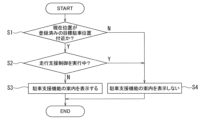
- FIG. 5 is a flowchart of the parking assistance method of the first embodiment.
- the controller 19 judges whether or not the current position of the vehicle 1 is near the target parking position 31. If the current position is not near the target parking position 31 (step S1: N), the process proceeds to step S4. If the current position is near the target parking position 31 (step S1: Y), the process proceeds to step S2.
- step S2 the controller 19 judges whether or not driving assistance control is being executed. If driving assistance control is not being executed (step S2: N), the process proceeds to step S4. If driving assistance control is being executed (step S2: Y), the process proceeds to step S3.
- step S3 the controller 19 displays a guide for the parking assistance function. The process then ends.
- the controller 19 does not display a guide for the parking assistance function. The process then ends.
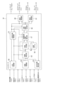
- Second Embodiment Fig. 6 is a block diagram of an example of the functional configuration of the parking assistance function by the controller in Fig. 1.
- the HMI control unit 50 detects a user's operation to register the target parking position 31, the HMI control unit 50 outputs a map generation command to the map generation unit 55 to store the learned target data in the storage device 19b.
- the image conversion unit 52 converts the captured image of the camera into an overhead image seen from a virtual viewpoint directly above the vehicle 1.
- the image conversion unit 52 converts the captured image into an overhead image at a predetermined interval, and accumulates the converted overhead images along the travel route of the vehicle 1 to generate a surrounding image that is an image of the area surrounding the vehicle 1.
- the vehicle position calculation unit 53 calculates the current position of the vehicle 1 on the map coordinate system as the vehicle position by odometry (e.g., dead reckoning) based on the vehicle information output from the vehicle sensor 16 .
- the target detection unit 54 detects a target from the surrounding image output from the image conversion unit 52.
- the target detection unit 54 may detect the position of a feature point of the target and its image feature amount as the target.
- the target detection unit 54 outputs the detected position of the feature point and the image feature amount as target data to the map generation unit 55 and the target parking position detection unit 57.
- the target detection unit 54 outputs the self-position acquired from the self-position calculation unit 53 to the map generation unit 55 and the target parking position detection unit 57 in synchronization with the detection of the target.
- the map generating unit 55 When the map generating unit 55 receives a map generating command from the HMI control unit 50 (i.e., when the target parking position 31 is registered), the map generating unit 55 generates learned target data and stores it in the storage device 19b as map data 56. For example, the map generating unit 55 receives target data and the vehicle's own position on the map coordinate system synchronized with the target data from the target detection unit 54. The map generating unit 55 acquires position information of the target parking position 31 in the map coordinate system. For example, the vehicle's own position calculated by the self-position calculation unit 53 when the vehicle 1 is located at the target parking position 31 may be acquired as the position information of the target parking position 31.
- the map generating unit 55 generates relative position data based on the positions of the feature points included in the target data, the position information of the vehicle 1 synchronized therewith, and the position information of the target parking position 31.
- the map generating unit 55 acquires feature amount data from the target data output from the target detection unit 54.
- the relative position data and feature amount data, as well as learned target data including the position data of the target parking position 31, are stored as map data 56 in the storage device 19b.
- the parking assist control unit 51 executes parking assist control to assist the parking of the host vehicle 1 at the target parking position 31 registered in the storage device 19b.
- the parking assist control unit 51 can be set by switching between an "automatic start mode” in which detection of the target parking position 31 existing around the vehicle 1 is automatically started, and a "manual start mode" in which detection of the target parking position 31 is started when a user operation (hereinafter sometimes referred to as a "start operation”) is performed to instruct the start of the parking assist control of the vehicle 1.
- the start operation may be the operation of the parking switch 17 by the user.
- the user can set the parking assist control unit 51 to either an automatic start mode or a manual start mode.
- detection of the target parking position 31 automatically starts when all of the following start conditions (A) to (C) are satisfied.
- determining whether the vehicle 1 is stopped for example, it may be determined whether the speed detected by the vehicle speed sensor is 0 km/h, and it may be determined that the vehicle 1 is stopped when the speed detected by the vehicle speed sensor is 0 km/h.
- a margin may be set, and it may be determined that the vehicle 1 is stopped when the speed detected by the vehicle speed sensor is equal to or lower than a predetermined speed.
- the parking assistance control unit 51 When all of the above start conditions (A) to (C) are satisfied in automatic start mode, or when a user start operation is accepted in manual start mode, the parking assistance control unit 51 outputs a parking position calculation command to the target parking position detection unit 57.
- the target parking position detection unit 57 receives the target data output from the target detection unit 54 as target data of surrounding targets, and receives the own position of the vehicle 1 in the map coordinate system in synchronization with this.
- the target parking position detection unit 57 detects the target parking position 31 by matching the learned targets with the surrounding targets and associating targets with the same characteristic points. In other words, it determines whether or not the target parking position 31 can be detected based on whether or not matching between the learned targets and the surrounding targets is successful.
- the target parking position detection unit 57 calculates the relative position of the vehicle 1 with respect to the target parking position 31 based on the relative positional relationship between the surrounding landmarks and the vehicle 1 and the relative positional relationship between the learned landmarks associated with the surrounding landmarks and the target parking position 31.
- the HMI control unit 50 displays a guide for the parking assistance function on the display device of the HMI 13. For example, while the parking assistance control unit 51 is searching for the target parking position 31 existing around the vehicle 1, the HMI control unit 50 displays the first guide screen 40a shown in FIG.
- the target parking position detection unit 57 automatically sets the detected target parking position 31 as the target parking position of the vehicle 1 supported by the parking assist function (the target parking position where the vehicle 1 is parked by the parking assist function).
- the HMI control unit 50 displays the second guidance screen 40b shown in FIG. 4 on the display device of the HMI 13.
- the function of automatically displaying guidance for the parking assist function when all of the start conditions (A) to (C) are satisfied is enabled.
- the function of automatically displaying the parking assist function guide is disabled. In this case, when the user's start operation is accepted, the target parking position detection unit 57 starts detecting the target parking position 31, and the HMI control unit 50 accordingly displays the parking assist function guide.
- the HMI control unit 50 may display the number of detected target parking positions 31 on the second guidance screen 40b.
- Fig. 4 shows an example in which, when the target parking position detection unit 57 detects two target parking positions 31, the number "2" representing the number of detected target parking positions 31 is displayed at the position of the parking position selection switch 18.
- the HMI control unit 50 may determine the priority of the target parking positions 31 according to a predetermined rule, and present the target parking positions 31 with higher priority on the second guidance screen 40b in preference to the target parking positions 31 with lower priority.
- the HMI control unit 50 may display a target parking position mark 42b representing the target parking position 31 with the highest priority. For example, the closer the target parking position 31 is to the vehicle 1, the higher the priority may be set. In addition, all of the multiple target parking positions existing around the vehicle 1 may be presented, or all of the multiple target parking positions existing around the vehicle 1 within a predetermined distance may be presented.
- the user may operate the parking position selection switch 18 to select one of a plurality of target parking positions 31 and set it as the target parking position of the vehicle 1 to be assisted by the parking assistance function.
- the HMI control unit 50 starts displaying the second guidance screen 40b, it may display the target parking position mark 42b representing the target parking position 31 with the highest priority.
- the HMI control unit 50 detects the operation of the parking position selection switch 18, it may select each of the multiple target parking positions 31 in order of priority, and display the target parking position mark 42b representing the selected target parking position 31.
- the target trajectory generation unit 59 calculates a target parking path from the current position of the host vehicle 1 on the vehicle coordinate system to the target parking position 31.
- the target trajectory generation unit 59 calculates a target vehicle speed profile that is a target value of the vehicle speed of the host vehicle 1 on the target parking path.
- the steering control unit 60 controls the steering actuator 21a so that the host vehicle 1 travels along the target parking path.
- the vehicle speed control unit 61 controls the accelerator actuator 21b and the brake actuator 21c so that the vehicle speed of the host vehicle 1 changes according to the target vehicle speed profile.
- the parking assistance control unit 51 activates the parking brake 20 and switches the shift position to the parking range.
- FIG. 7 is a flowchart of the parking assistance method of the second embodiment.
- the parking assistance control unit 51 determines whether the current position of the vehicle 1 is near the target parking position 31. If the current position is not near the target parking position 31 (step S10: N), the process proceeds to step S17. If the current position is near the target parking position 31 (step S10: Y), the process proceeds to step S11.
- the parking assistance control unit 51 determines whether the vehicle speed of the vehicle is equal to or less than a threshold value. If the vehicle speed is not equal to or less than the threshold value (step S11: N), the process proceeds to step S17. If the vehicle speed is equal to or less than the threshold value (step S11: Y), the process proceeds to step S12.
- step S12 the parking assist control unit 51 determines whether driving assist control is being executed. If driving assist control is not being executed (step S12: N), the process proceeds to step S14. If driving assist control is being executed (step S12: Y), the process proceeds to step S13.
- step S13 the parking assist control unit 51 determines whether a driving operation by the user has occurred. If a driving operation has not occurred (step S13: N), the process proceeds to step S17. If a driving operation has occurred (step S13: Y), the process proceeds to step S14.
- step S14 the parking assist control unit 51 determines whether the automatic start mode is set. If the automatic start mode is set (step S14: Y), the process proceeds to step S16. If the automatic start mode is not set (step S14: N), the process proceeds to step S15.
- step S15 the parking assist control unit 51 determines whether or not the parking switch 17 has been operated. If the parking switch 17 has not been operated (step S15: N), the process proceeds to step S17. If the parking switch 17 has been operated (step S15: Y), the process proceeds to step S16. In step S16, the controller 19 displays the information about the parking assist function. The process then ends. In step S17, the controller 19 does not display the information about the parking assist function. The process then ends.
- the controller 19 determines whether or not driving support control including at least one of control to assist the host vehicle 1 in driving within a driving lane, control to assist the host vehicle 1 in driving at a constant speed, and control to assist the host vehicle 1 in maintaining a constant distance between the host vehicle 1 and a preceding vehicle is being executed, determines whether or not the host vehicle 1 is located near a preregistered target parking position, and displays on the display device guidance for a parking support function that assists the host vehicle 1 in parking at the target parking position when the driving support control is not being executed and the host vehicle 1 is located near the target parking position, and does not display guidance for the parking support function when the driving support control is being executed or when the host vehicle 1 is not located near the target parking position. In this way, when the driving support control is being executed, it is presumed that the user does not intend to park the host vehicle 1, and by not displaying guidance for the parking support function, unnecessary display of guidance for the parking support function can be suppressed.
- the controller 19 may display guidance for the parking assist function on the display device when the vehicle speed is equal to or lower than a threshold, driving assist control is not being executed, and the vehicle 1 is located near the target parking position.
- the controller 19 may not display guidance for the parking assist function on the display device. In this way, when the vehicle speed is higher than the threshold, it is assumed that the user does not intend to park the vehicle 1, and by not displaying guidance for the parking assist function, unnecessary display of guidance for the parking assist function can be suppressed.
- the controller 19 may display guidance for the parking assist function on the display device when the host vehicle 1 is stopped, driving assist control is not being executed, and the host vehicle 1 is located near the target parking position. It is not necessary to display guidance for the parking assist function on the display device when the host vehicle 1 is not stopped, driving assist control is being executed, or the host vehicle 1 is not located near the target parking position. In this way, by presuming that the user does not intend to park the host vehicle 1 when the host vehicle 1 is not stopped and not displaying guidance for the parking assist function, unnecessary display of guidance for the parking assist function can be suppressed.
- the controller 19 may display a guide for the parking assistance function and may select a preregistered target parking position detected near the vehicle 1 as the target parking position of the vehicle 1 to be supported by the parking assistance function. This can reduce the user's manual operation for setting the target parking position.
- the controller 19 may store data representing the relative positional relationship between the target parking position and targets existing around the target parking position in advance as learned target data in the storage device, detect surrounding targets that are targets existing around the vehicle 1, and detect the target parking position existing around the vehicle 1 based on the learned target data and the surrounding targets. This allows the user to use parking assist control that assists in parking the vehicle 1 at the target parking position registered in advance.
- the controller 19 may display on the display device the target parking positions in order of proximity to the current position of the vehicle 1. This allows the target parking positions to be suggested in order of the one that is most likely to be selected by the user, thereby reducing the manual operation of the user to select the target parking position.
- the function of displaying guidance for the parking assist function on the display device may be disabled by a setting based on a user's input to a user interface of the vehicle 1. If the function of displaying guidance for the parking assist function on the display device is disabled by a setting based on a user's input to a user interface of the vehicle 1, guidance for the parking assist function may be displayed on the display device when a user's operation input instructing activation of the parking assist function is received. This allows guidance for the parking assist function to be displayed on the display device according to the user's preferences.
- a guide for the parking assist function may be displayed on the display device.
- an intervention operation on the steering wheel is detected while driving assist control that assists the vehicle 1 in driving within a driving lane is being executed and the vehicle 1 is located near the target parking position
- a guide for the parking assist function may be displayed on the display device. In this way, if a driving operation by the user occurs even while driving assist control is being executed, it is presumed that the user intends to park the vehicle 1, and a guide for the parking assist function is displayed, thereby reducing the manual operation by the user to activate the parking assist function.
Landscapes
- Engineering & Computer Science (AREA)
- Chemical & Material Sciences (AREA)
- Combustion & Propulsion (AREA)
- Transportation (AREA)
- Mechanical Engineering (AREA)
- Traffic Control Systems (AREA)
Abstract
Description
本発明は、目標駐車位置への駐車を支援する駐車支援機能を有する車両において、駐車支援機能の案内の不要な表示を抑制することを目的とする。
本発明の目的及び利点は、特許請求の範囲に示した要素及びその組合せを用いて具現化され達成される。前述の一般的な記述及び以下の詳細な記述の両方は、単なる例示及び説明であり、特許請求の範囲のように本発明を限定するものでないと解するべきである。
(構成)
図1は、実施形態の運転支援装置の概略構成例を示す図である。自車両1は、駐車支援機能と走行支援機能とを有する運転支援装置10を備える。運転支援装置10は、特許請求の範囲に記載の「運転支援装置」の一例である。
駐車支援機能は、自車両1の現在位置から目標駐車位置までの目標駐車経路に沿って走行することを支援する機能である。例えば運転支援装置10は、自車両1の目標駐車経路に沿って目標駐車位置まで走行するように自車両1を制御する自動運転を行ってもよい。自車両1の目標駐車経路に沿って目標駐車位置まで走行するように制御する自動運転とは、自車両1の操舵角、駆動力、制動力の全部または一部を制御して、自車両1の目標駐車経路に沿った走行の全部または一部を自動的に実施する制御を意味する。また、目標駐車経路と自車両1の現在位置とを自車両1に乗っているユーザ(例えば運転者等の乗員)が視認可能な表示装置に表示することによって、自車両1の駐車を支援してもよい。
なお、以下の説明において駐車支援機能、走行支援機能、車線維持支援機能、定速走行支援機能及び車間維持支援機能を実現するための運転支援装置10による制御をそれぞれ「駐車支援制御」、「走行支援制御」、「車線維持支援制御」、「定速走行支援制御」及び「車間維持支援制御」と表記することがある。
ヒューマンマシンインタフェース(HMI)13は、運転支援装置10とユーザとの間で情報を授受するインタフェース装置である。例えばHMI13は、ユーザに視覚的情報を提示するインタフェースとしてユーザが視認可能な表示装置を備えてよい。またHMI13は、ユーザに聴覚的情報を提示するインタフェースとしてスピーカやブザーを備えてもよい。またHMI13は、ユーザからの操作入力を受け付けるインタフェース(タッチパネル、ボタン、スイッチ、レバー、ダイヤル、キーボード等)を備えてもよい。
外界センサ15は、自車両1から所定距離範囲の物体を検出する。外界センサ15は、自車両1の周囲に存在する物体と自車両1との相対位置、自車両1と物体との距離、物体が存在する方向などの自車両1の周囲環境を検出する。外界センサ15は、例えば自車両1の周囲環境を撮影するカメラを含んでよい。外界センサ15は、レーザレンジファインダやレーダ、LiDAR(Light Detection and Ranging)、ソナー等の測距装置を含んでもよい。車両センサ16は、自車両1の様々な情報(車両情報)を検出する。例えば車両センサ16は、自車両1の走行速度を検出する車速センサ、自車両1の3軸方向の加速度(減速度を含む)を検出する3軸加速度センサ、ハンドルの操舵角や転舵輪の転舵角を検出するセンサを含んでよい。
駐車位置選択スイッチ(駐車位置選択SW)18は、自車両1の周囲に複数の目標駐車位置の候補が存在する際に、これらの候補のいずれかをユーザが選択する操作を受け付けるスイッチである。例えばHMI13の表示装置にタッチパネルを設け、表示装置に表示された駐車位置選択スイッチ18の画像をユーザが触る操作をタッチパネルで検出してよい。
ステアリングアクチュエータ21aは、コントローラ19の制御信号に応じて自車両1の操舵機構の操舵方向及び操舵量を制御する。アクセルアクチュエータ21bは、コントローラ19の制御信号に応じて、エンジンや駆動モータである駆動装置のアクセル開度を制御する。ブレーキアクチュエータ21cは、コントローラ19の制御信号に応じて制動装置を作動させる。
例えば、車線維持支援機能においてコントローラ19は、外界センサ15の検出信号に基づいて自車両1が走行する車線である走行車線の車線区分線を認識し、自車両1が走行車線に沿って走行するように(例えば自車両1が走行車線内の所定の横方向位置を走行するように)ステアリングアクチュエータ21aを制御したり、ユーザの操舵操作を促す通知をHMI13から出力してよい。
また例えば車間維持支援制御においてコントローラ19は、外界センサ15の検出信号に基づいて自車両1と先行車両との間の車間距離を認識し、車間距離を一定に維持するようにアクセルアクチュエータ21bとブレーキアクチュエータ21cを制御したり、ユーザの加減速操作を促す通知をHMI13から出力してよい。
運転支援装置10に目標駐車位置31を登録する際には、目標駐車位置31の周囲に存在する物標を抽出して予め記憶装置19bに記憶(登録)する。以下の説明において記憶装置19bに記憶する目標駐車位置31の周囲の物標を「学習済物標」と表記する。図2(a)において丸プロットは学習済物標を模式的に表す。目標駐車位置31を運転支援装置10に登録する際、ユーザは目標駐車位置31の登録を指示する操作(以下「登録操作」と表記することがある)を行う。
コントローラ19は、学習済物標に関する学習済物標データを記憶装置19bに記憶する。例えば学習済物標データは、学習済物標の特徴量を表すデータ(以下「特徴量データ」と表記する)と、目標駐車位置31と学習済物標との間の相対位置関係のデータ(以下「相対位置データ」と表記する)と、固定の地点を基準点とする座標系(以下「地図座標系」と表記する)における目標駐車位置31の位置データを含んでよい。
相対位置データとして、例えば目標駐車位置31を基準とする学習済物標の相対位置を記憶してもよい。例えば、コントローラ19は、自車両1が目標駐車位置31に駐車したときに検出した学習済物標の位置を、目標駐車位置31を基準とする学習済物標の相対位置として取得できる。地図座標系における学習済物標と目標駐車位置31の座標を記憶してもよい。
コントローラ19は、自車両1の現在位置33から目標駐車位置31へ至るまでの目標駐車経路34を算出する。コントローラ19は、算出した目標駐車経路34に基づいて自車両1の駐車支援制御を実施する。
図3は、第1案内画面の一例の模式図である。第1案内画面40aは、自車両1の周囲を撮像して生成した撮像画像41と、自車両1の周囲の撮像画像を変換して生成した俯瞰画像42と、駐車位置選択スイッチ18のGUI(Graphical User Interface)と、視覚的メッセージ等の通知が表示されるメッセージ表示領域43と、駐車開始ボタン44と、終了ボタン45を含む。表示装置に表示された駐車位置選択スイッチ18や終了ボタン45をユーザが操作すると、表示装置に設けられたタッチパネルがこれらの操作を検出する。ない、第1案内画面40aでは駐車開始ボタン44は無効化されている。
俯瞰画像42には、自車両1の現在位置を表すアイコン42aが重畳表示される。第1案内画面40aのメッセージ表示領域43には、例えば目標駐車位置を探索中であることをユーザに知らせる視覚的メッセージ等の通知を表示してよい。終了ボタン45が操作されると、コントローラ19は駐車支援制御を中止する。図4に示す後述の第2案内画面40bの終了ボタン45が操作された場合も同様である。
図4は、第2案内画面の一例の模式図である。第2案内画面40bは、撮像画像41と、俯瞰画像42と、メッセージ表示領域43と、駐車位置選択スイッチ18のGUIと、駐車開始ボタン44と、終了ボタン45を含む。駐車開始ボタン44をユーザが操作すると、表示装置に設けられたタッチパネルがこれらの操作を検出する。
駐車開始ボタン44が操作されると、コントローラ19は目標駐車位置31への自車両1の駐車の支援を開始する。上記のとおり図3の第1案内画面40aでは駐車開始ボタン44が無効化されており、第1案内画面40aで駐車開始ボタン44が操作されも、コントローラ19は駐車の支援を開始しない。
そこでコントローラ19は、走行支援制御が実行されているか否かを判定する。また、目標駐車位置31付近に自車両1が位置しているか否かを判定する(例えば、目標駐車位置31の所定距離範囲内に自車両1が位置しているか否かを判定する)。例えば、測位装置11が測定した自車両1の現在位置が、学習済物標データとして記憶した目標駐車位置31の位置からの所定距離範囲内にあるか否かを判定する。
コントローラ19は、走行支援制御が実行されておらず、且つ自車両1が目標駐車位置31付近に位置している場合に駐車支援機能の案内をHMI13の表示装置に自動的に表示する。走行支援制御が実行されているか、又は自車両1が目標駐車位置31付近に位置していない場合には、駐車支援機能の案内を表示装置に自動的に表示しない。
走行支援制御が実行されている場合には、ユーザが自車両1を駐車することを意図していないと推定される。このため、目標駐車位置31付近に自車両1が位置していても走行支援制御が実行されている場合には駐車支援機能の案内を表示しないことにより、駐車支援機能の案内の不要な表示を抑制できる。
図5は、第1実施形態の駐車支援方法のフローチャートである。ステップS1においてコントローラ19は、自車両1の現在位置が目標駐車位置31付近であるか否かを判定する。現在位置が目標駐車位置31付近でない場合(ステップS1:N)に処理はステップS4へ進む。現在位置が目標駐車位置31付近である場合(ステップS1:Y)に処理はステップS2へ進む。ステップS2においてコントローラ19は、走行支援制御が実行されているか否かを判定する。走行支援制御が実行されていない場合(ステップS2:N)に処理はステップS4へ進む。走行支援制御が実行されている場合(ステップS2:Y)に処理はステップS3へ進む。ステップS3においてコントローラ19は、駐車支援機能の案内を表示する。その後に処理は終了する。ステップS4においてコントローラ19は、駐車支援機能の案内を表示しない。その後に処理は終了する。
図6は、図1のコントローラによる駐車支援機能の機能構成の一例のブロック図である。HMI制御部50は、ユーザによる目標駐車位置31の登録操作を検出すると、学習済物標データを記憶装置19bに記憶させる地図生成指令を地図生成部55に出力する。
画像変換部52は、カメラの撮像画像を、自車両1の真上の仮想視点から見た俯瞰画像に変換する。画像変換部52は、所定の間隔で撮像画像を俯瞰画像に変換し、変換された俯瞰画像を自車両1の走行経路に沿って蓄積することで自車両1の周囲領域の画像である周囲画像を生成する。
物標検出部54は、画像変換部52から出力される周囲画像から物標を検出する。物標検出部54は、物標として物標の特徴点の位置とその画像特徴量を検出してよい。物標検出部54は、検出した特徴点の位置と画像特徴量を物標データとして地図生成部55と目標駐車位置検出部57に出力する。また、物標の検出と同期して自己位置算出部53から取得した自己位置を地図生成部55と目標駐車位置検出部57に出力する。
地図生成部55は、地図生成指令をHMI制御部50から受信すると(すなわち、目標駐車位置31の登録操作が行われると)、学習済物標データを生成して地図データ56として記憶装置19bに記憶する。例えば地図生成部55は、物標検出部54から、物標データと、物標データに同期した地図座標系上の自車両1の自己位置を受信する。地図生成部55は、地図座標系における目標駐車位置31の位置情報を取得する。例えば、自車両1が目標駐車位置31に位置するときに自己位置算出部53が算出した自己位置を目標駐車位置31の位置情報として取得してよい。地図生成部55は、物標データに含まれる特徴点の位置と、これに同期した自車両1の位置情報と、目標駐車位置31の位置情報とに基づいて、相対位置データを生成する。地図生成部55は、物標検出部54から出力される物標データから特徴量データを取得する。これら相対位置データ及び特徴量データと、目標駐車位置31の位置データを含んだ学習済物標データを地図データ56として記憶装置19bに記憶する。
駐車支援制御部51は、自車両1の周囲に存在する目標駐車位置31の検出を自動的に開始する「自動開始モード」と、自車両1の駐車支援制御の起動を指示するユーザの操作(以下「起動操作」と表記することがある)が行われたときに目標駐車位置31の検出を開始する「手動開始モード」に切り替えて設定できる。例えば起動操作は、ユーザによるパーキングスイッチ17の操作であってよい。
ユーザは、HMI13を操作することにより、駐車支援制御部51を自動開始モードと手動開始モードとのいずれかに設定できる。
(A)自車両1が目標駐車位置31付近に位置する(例えば目標駐車位置31の所定距離範囲内に自車両1が位置する)。
(B)自車両1の車速が閾値以下である(例えば、自車両1が停止している)。
(C)走行支援制御が実行されていない。又は、走行支援制御の実行中にユーザの運転操作が発生した(例えば走行支援制御の実行中にユーザによるブレーキ操作を検出したり、車線維持支援制御の実行中にユーザによるステアリングホイールへの介入操作を検出した)。
ここで、自車両1が停止しているか否かを判定する際には、例えば車速センサによる検出速度が0km/hか否かを判定し、車速センサによる検出速度が0km/hの場合に自車両1が停止していると判断してよい。マージンを設定し、車速センサの検出速度が所定速度以下の場合に、自車両1が停止したと判定してもよい。
自車両1の周囲に存在する目標駐車位置31を検出すると、目標駐車位置検出部57は、検出した目標駐車位置31を、駐車支援機能により支援される自車両1の目標駐車位置(駐車支援機能により自車両1を駐車する目標駐車位置)として自動的に設定する。また、HMI制御部50は、図4に示す第2案内画面40bをHMI13の表示装置に表示する。
また、ユーザが駐車支援制御部51を手動開始モードに設定すると、駐車支援機能の案内を自動的に表示する機能が無効になる。この場合には、ユーザの起動操作を受け付けたときに、目標駐車位置検出部57が目標駐車位置31の検出を開始し、これに伴ってHMI制御部50が駐車支援機能の案内を表示する。
このように、自車両1の周囲に存在する複数の目標駐車位置31を検出した場合、HMI制御部50は、予め定めた規則に従って目標駐車位置31の優先順位を決定して、優先順位の高い目標駐車位置31を優先順位の低い目標駐車位置31よりも優先して第2案内画面40bに提示してもよい。例えばHMI制御部50は、優先順位が最も高い目標駐車位置31を表す目標駐車位置マーク42bを表示してよい。例えば、自車両1に近い目標駐車位置31ほど、より高い優先順位を設定してよい。
また、自車両1の周囲に存在する複数の目標駐車位置全てを提示してもよいし、自車両1から所定距離内の周囲に存在する複数の目標駐車位置全てを提示してもよい。
例えばHMI制御部50は、第2案内画面40bの表示を開始する時点では、最も優先順位が高い目標駐車位置31を表す目標駐車位置マーク42bを表示してよい。HMI制御部50は、駐車位置選択スイッチ18の操作を検出すると、優先順位が高い順に複数の目標駐車位置31の各々を順々に選択して、選択した目標駐車位置31を表す目標駐車位置マーク42bを表示してよい。
ステップS16においてコントローラ19は、駐車支援機能の案内を表示する。その後に処理は終了する。ステップS17においてコントローラ19は、駐車支援機能の案内を表示しない。その後に処理は終了する。
(1)コントローラ19は、自車両1が走行車線内を走行することを支援する制御、自車両1が一定速度で走行することを支援する制御、又は自車両1と先行車両との間の車間距離を一定に維持することを支援する制御の少なくともいずれか1つを含む走行支援制御が実行されているか否かを判定し、予め登録した目標駐車位置付近に自車両1が位置しているか否かを判定し、走行支援制御が実行されておらず、且つ自車両1が目標駐車位置付近に位置している場合に、目標駐車位置への自車両1の駐車を支援する駐車支援機能の案内を表示装置に表示し、走行支援制御が実行されている場合、又は自車両1が目標駐車位置付近に位置していない場合に、駐車支援機能の案内を表示装置に表示しない。このように、走行支援制御が実行されている場合にはユーザが自車両1を駐車することを意図していないと推定して駐車支援機能の案内を表示しないことにより、駐車支援機能の案内の不要な表示を抑制できる。
(5)コントローラ19は、予め、目標駐車位置の周囲に存在する物標と目標駐車位置との相対位置関係を表すデータを学習済物標データとして記憶装置に記憶し、自車両1の周囲に存在する物標である周囲物標を検出し、学習済物標データと周囲物標とに基づいて、自車両1の周囲に存在する目標駐車位置を検出してよい。これにより、ユーザは予め登録した目標駐車位置への自車両1の駐車支援する駐車支援制御を利用できる。
(7)駐車支援機能の案内を表示装置に表示する機能を、自車両1のユーザのユーザインタフェースへの入力により設定により無効にしてもよい。駐車支援機能の案内を表示装置に表示する機能がユーザのユーザインタフェースへの入力により設定により無効に設定されている場合、駐車支援機能の起動を指示するユーザの操作入力を受け付けると、駐車支援機能の案内を表示装置に表示してよい。これにより、ユーザの好みに応じて駐車支援機能の案内を表示装置に表示することができる。
Claims (10)
- 目標駐車位置への自車両の駐車を支援する駐車支援方法であって、
前記自車両が走行車線内を走行することを支援する制御、前記自車両が一定速度で走行することを支援する制御、又は前記自車両と先行車両との間の車間距離を一定に維持することを支援する制御の少なくとも1つを含む走行支援制御が実行されているか否かを判定し、
予め登録した前記目標駐車位置付近に前記自車両が位置しているか否かを判定し、
前記走行支援制御が実行されておらず、且つ前記自車両が前記目標駐車位置付近に位置している場合に、前記目標駐車位置への前記自車両の駐車を支援する駐車支援機能の案内を表示装置に表示し、
前記走行支援制御が実行されている場合、又は前記自車両が前記目標駐車位置付近に位置していない場合に、前記駐車支援機能の案内を前記表示装置に表示しない、
ことを特徴とする駐車支援方法。 - 前記自車両の車速が閾値以下であり、且つ前記走行支援制御が実行されておらず、且つ前記自車両が前記目標駐車位置付近に位置している場合に、前記駐車支援機能の案内を前記表示装置に表示し、
前記車速が前記閾値より高い場合、前記走行支援制御が実行されている場合、又は前記自車両が前記目標駐車位置付近に位置していない場合に前記駐車支援機能の案内を前記表示装置に表示しない、
ことを特徴とする請求項1に記載の駐車支援方法。 - 前記自車両が停止しており、且つ前記走行支援制御が実行されておらず、且つ前記自車両が前記目標駐車位置付近に位置している場合に、前記駐車支援機能の案内を前記表示装置に表示し、
前記自車両が停止していない場合、前記走行支援制御が実行されている場合、又は前記自車両が前記目標駐車位置付近に位置していない場合に、前記駐車支援機能の案内を前記表示装置に表示しない、
ことを特徴とする請求項1に記載の駐車支援方法。 - 前記駐車支援機能の案内を表示するとともに、前記自車両の付近で検出した予め登録した前記目標駐車位置を、前記駐車支援機能により支援される前記自車両の目標駐車位置として選択することを特徴とする請求項1~3のいずれか一項に記載の駐車支援方法。
- 予め、前記目標駐車位置の周囲に存在する物標と前記目標駐車位置との相対位置関係を表すデータを学習済物標データとして記憶装置に記憶し、
前記自車両の周囲に存在する物標である周囲物標を検出し、
前記学習済物標データと前記周囲物標とに基づいて、前記自車両の周囲に存在する前記目標駐車位置を検出する、
ことを特徴とする請求項1~4のいずれか一項に記載の駐車支援方法。 - 前記駐車支援の案内として前記自車両の現在位置に対して近い順で、前記目標駐車位置を前記表示装置に表示することを特徴とする請求項4に記載の駐車支援方法。
- 前記駐車支援機能の案内を前記表示装置に表示する機能を、前記自車両のユーザのユーザインタフェースへの入力により無効に設定でき、
前記駐車支援機能の案内を前記表示装置に表示する機能が前記ユーザの前記ユーザインタフェースへの入力により無効に設定されている場合、前記駐車支援機能の起動を指示するユーザの操作入力を受け付けると、前記駐車支援機能の案内を前記表示装置に表示することを特徴とする請求項1~6のいずれか一項に記載の駐車支援方法。 - 前記走行支援制御の実行中にブレーキ操作が検出され、且つ前記自車両が前記目標駐車位置付近に位置している場合に、前記駐車支援機能の案内を前記表示装置に表示することを特徴とする請求項1~7のいずれか一項に記載の駐車支援方法。
- 前記自車両が走行車線内を走行することを支援する前記走行支援制御の実行中にステアリングホイールへの介入操作が検出され、且つ前記自車両が前記目標駐車位置付近に位置している場合に、前記駐車支援機能の案内を前記表示装置に表示することを特徴とする請求項1~8のいずれか一項に記載の駐車支援方法。
- 目標駐車位置への自車両の駐車を支援する駐車支援装置であって、
表示装置と、
前記自車両が走行車線内を走行することを支援する制御、前記自車両が一定速度で走行することを支援する制御、又は前記自車両と先行車両との間の車間距離を一定に維持することを支援する制御の少なくとも1つを含む走行支援制御が実行されているか否かを判定し、予め登録した前記目標駐車位置付近に前記自車両が位置しているか否かを判定し、前記走行支援制御が実行されておらず、且つ前記自車両が前記目標駐車位置付近に位置している場合に、前記目標駐車位置への前記自車両の駐車を支援する駐車支援機能の案内を前記表示装置表示し、前記走行支援制御が実行されている場合、又は前記自車両が前記目標駐車位置付近に位置していない場合に、前記駐車支援機能の案内を前記表示装置に表示しないコントローラと、
を備えることを特徴とする運転支援装置。
Priority Applications (4)
| Application Number | Priority Date | Filing Date | Title |
|---|---|---|---|
| PCT/JP2023/002588 WO2024157443A1 (ja) | 2023-01-27 | 2023-01-27 | 駐車支援方法及び運転支援装置 |
| JP2024572776A JPWO2024157443A1 (ja) | 2023-01-27 | 2023-01-27 | |
| EP23918068.0A EP4656477A4 (en) | 2023-01-27 | 2023-01-27 | METHOD AND DEVICE FOR PARKING ASSISTANCE |
| CN202380091427.4A CN120476065A (zh) | 2023-01-27 | 2023-01-27 | 停车辅助方法及驾驶辅助装置 |
Applications Claiming Priority (1)
| Application Number | Priority Date | Filing Date | Title |
|---|---|---|---|
| PCT/JP2023/002588 WO2024157443A1 (ja) | 2023-01-27 | 2023-01-27 | 駐車支援方法及び運転支援装置 |
Publications (1)
| Publication Number | Publication Date |
|---|---|
| WO2024157443A1 true WO2024157443A1 (ja) | 2024-08-02 |
Family
ID=91970080
Family Applications (1)
| Application Number | Title | Priority Date | Filing Date |
|---|---|---|---|
| PCT/JP2023/002588 Ceased WO2024157443A1 (ja) | 2023-01-27 | 2023-01-27 | 駐車支援方法及び運転支援装置 |
Country Status (4)
| Country | Link |
|---|---|
| EP (1) | EP4656477A4 (ja) |
| JP (1) | JPWO2024157443A1 (ja) |
| CN (1) | CN120476065A (ja) |
| WO (1) | WO2024157443A1 (ja) |
Cited By (1)
| Publication number | Priority date | Publication date | Assignee | Title |
|---|---|---|---|---|
| CN119091678A (zh) * | 2024-09-12 | 2024-12-06 | 中国第一汽车股份有限公司 | 一种引导停车的方法、装置、设备、存储介质和产品 |
Citations (4)
| Publication number | Priority date | Publication date | Assignee | Title |
|---|---|---|---|---|
| JP2008261703A (ja) * | 2007-04-11 | 2008-10-30 | Toyota Motor Corp | 車載機器機能説明装置 |
| JP2008305319A (ja) * | 2007-06-11 | 2008-12-18 | Toyota Motor Corp | 運転支援装置案内システム、表示装置 |
| JP2021154837A (ja) * | 2020-03-26 | 2021-10-07 | 本田技研工業株式会社 | 駐車支援システム |
| JP2022133230A (ja) | 2021-03-01 | 2022-09-13 | パナソニックIpマネジメント株式会社 | 駐車支援方法および駐車支援装置 |
Family Cites Families (4)
| Publication number | Priority date | Publication date | Assignee | Title |
|---|---|---|---|---|
| WO2011039822A1 (ja) * | 2009-10-02 | 2011-04-07 | 三菱電機株式会社 | 駐車支援装置 |
| WO2017179198A1 (ja) * | 2016-04-15 | 2017-10-19 | 三菱電機株式会社 | 駐車支援装置 |
| KR20210144945A (ko) * | 2017-07-07 | 2021-11-30 | 닛산 지도우샤 가부시키가이샤 | 주차 지원 방법 및 주차 지원 장치 |
| JP7328116B2 (ja) * | 2019-10-11 | 2023-08-16 | トヨタ自動車株式会社 | 駐車支援装置 |
-
2023
- 2023-01-27 EP EP23918068.0A patent/EP4656477A4/en active Pending
- 2023-01-27 CN CN202380091427.4A patent/CN120476065A/zh active Pending
- 2023-01-27 JP JP2024572776A patent/JPWO2024157443A1/ja active Pending
- 2023-01-27 WO PCT/JP2023/002588 patent/WO2024157443A1/ja not_active Ceased
Patent Citations (4)
| Publication number | Priority date | Publication date | Assignee | Title |
|---|---|---|---|---|
| JP2008261703A (ja) * | 2007-04-11 | 2008-10-30 | Toyota Motor Corp | 車載機器機能説明装置 |
| JP2008305319A (ja) * | 2007-06-11 | 2008-12-18 | Toyota Motor Corp | 運転支援装置案内システム、表示装置 |
| JP2021154837A (ja) * | 2020-03-26 | 2021-10-07 | 本田技研工業株式会社 | 駐車支援システム |
| JP2022133230A (ja) | 2021-03-01 | 2022-09-13 | パナソニックIpマネジメント株式会社 | 駐車支援方法および駐車支援装置 |
Non-Patent Citations (1)
| Title |
|---|
| See also references of EP4656477A1 |
Cited By (1)
| Publication number | Priority date | Publication date | Assignee | Title |
|---|---|---|---|---|
| CN119091678A (zh) * | 2024-09-12 | 2024-12-06 | 中国第一汽车股份有限公司 | 一种引导停车的方法、装置、设备、存储介质和产品 |
Also Published As
| Publication number | Publication date |
|---|---|
| EP4656477A4 (en) | 2026-03-18 |
| EP4656477A1 (en) | 2025-12-03 |
| JPWO2024157443A1 (ja) | 2024-08-02 |
| CN120476065A (zh) | 2025-08-12 |
Similar Documents
| Publication | Publication Date | Title |
|---|---|---|
| JPWO2019058781A1 (ja) | 駐車支援装置 | |
| US20200180510A1 (en) | Parking Assistance Method and Parking Assistance Device | |
| JP7816484B2 (ja) | 駐車支援方法及び駐車支援装置 | |
| US12472935B2 (en) | Control device, control method, and computer-readable recording medium | |
| WO2024157443A1 (ja) | 駐車支援方法及び運転支援装置 | |
| CN117677553B (zh) | 驻车辅助方法以及驻车辅助装置 | |
| WO2024157441A1 (ja) | 駐車支援方法及び駐車支援装置 | |
| WO2024157444A1 (ja) | 駐車支援方法及び駐車支援装置 | |
| WO2024157442A1 (ja) | 駐車支援方法及び駐車支援装置 | |
| JP2011198002A (ja) | 車両用対象物画像認識装置、車両用対象物画像認識方法及びコンピュータプログラム | |
| WO2024184974A1 (ja) | 駐車支援方法及び駐車支援装置 | |
| JP7771820B2 (ja) | 駐車支援方法及び駐車支援装置 | |
| WO2024157449A1 (ja) | 駐車支援方法及び駐車支援装置 | |
| US12415505B2 (en) | Parking assisting method and parking assistance device | |
| WO2025088729A1 (ja) | 駐車支援方法及び駐車支援装置 | |
| WO2025088730A1 (ja) | 駐車支援方法及び駐車支援装置 | |
| WO2024157460A1 (ja) | 駐車支援方法及び駐車支援装置 | |
| WO2024157461A1 (ja) | 駐車支援方法及び駐車支援装置 | |
| JP7740561B2 (ja) | 駐車支援方法及び駐車支援装置 | |
| WO2024157459A1 (ja) | 駐車支援方法及び駐車支援装置 | |
| WO2026033704A1 (ja) | 駐車支援方法及び駐車支援装置 | |
| WO2025210786A1 (ja) | 駐車支援方法、駐車支援装置及びコンピュータプログラム | |
| WO2024013807A1 (ja) | 駐車支援方法及び駐車支援装置 |
Legal Events
| Date | Code | Title | Description |
|---|---|---|---|
| 121 | Ep: the epo has been informed by wipo that ep was designated in this application |
Ref document number: 23918068 Country of ref document: EP Kind code of ref document: A1 |
|
| WWE | Wipo information: entry into national phase |
Ref document number: 2024572776 Country of ref document: JP |
|
| WWE | Wipo information: entry into national phase |
Ref document number: 202380091427.4 Country of ref document: CN |
|
| WWP | Wipo information: published in national office |
Ref document number: 202380091427.4 Country of ref document: CN |
|
| NENP | Non-entry into the national phase |
Ref country code: DE |
|
| WWP | Wipo information: published in national office |
Ref document number: 2023918068 Country of ref document: EP |