WO2024157974A1 - 硫化物固体電解質粉末の製造方法 - Google Patents
硫化物固体電解質粉末の製造方法 Download PDFInfo
- Publication number
- WO2024157974A1 WO2024157974A1 PCT/JP2024/001852 JP2024001852W WO2024157974A1 WO 2024157974 A1 WO2024157974 A1 WO 2024157974A1 JP 2024001852 W JP2024001852 W JP 2024001852W WO 2024157974 A1 WO2024157974 A1 WO 2024157974A1
- Authority
- WO
- WIPO (PCT)
- Prior art keywords
- powder
- solid electrolyte
- sulfide
- sulfide solid
- container
- Prior art date
- Legal status (The legal status is an assumption and is not a legal conclusion. Google has not performed a legal analysis and makes no representation as to the accuracy of the status listed.)
- Ceased
Links
Images


Classifications
-
- H—ELECTRICITY
- H01—ELECTRIC ELEMENTS
- H01M—PROCESSES OR MEANS, e.g. BATTERIES, FOR THE DIRECT CONVERSION OF CHEMICAL ENERGY INTO ELECTRICAL ENERGY
- H01M10/00—Secondary cells; Manufacture thereof
- H01M10/05—Accumulators with non-aqueous electrolyte
- H01M10/056—Accumulators with non-aqueous electrolyte characterised by the materials used as electrolytes, e.g. mixed inorganic/organic electrolytes
- H01M10/0561—Accumulators with non-aqueous electrolyte characterised by the materials used as electrolytes, e.g. mixed inorganic/organic electrolytes the electrolyte being constituted of inorganic materials only
- H01M10/0562—Solid materials
-
- C—CHEMISTRY; METALLURGY
- C01—INORGANIC CHEMISTRY
- C01B—NON-METALLIC ELEMENTS; COMPOUNDS THEREOF; METALLOIDS OR COMPOUNDS THEREOF NOT COVERED BY SUBCLASS C01C
- C01B17/00—Sulfur; Compounds thereof
- C01B17/22—Alkali metal sulfides or polysulfides
-
- C—CHEMISTRY; METALLURGY
- C01—INORGANIC CHEMISTRY
- C01B—NON-METALLIC ELEMENTS; COMPOUNDS THEREOF; METALLOIDS OR COMPOUNDS THEREOF NOT COVERED BY SUBCLASS C01C
- C01B25/00—Phosphorus; Compounds thereof
- C01B25/14—Sulfur, selenium, or tellurium compounds of phosphorus
-
- C—CHEMISTRY; METALLURGY
- C01—INORGANIC CHEMISTRY
- C01D—COMPOUNDS OF ALKALI METALS, i.e. LITHIUM, SODIUM, POTASSIUM, RUBIDIUM, CAESIUM, OR FRANCIUM
- C01D15/00—Lithium compounds
-
- H—ELECTRICITY
- H01—ELECTRIC ELEMENTS
- H01B—CABLES; CONDUCTORS; INSULATORS; SELECTION OF MATERIALS FOR THEIR CONDUCTIVE, INSULATING OR DIELECTRIC PROPERTIES
- H01B1/00—Conductors or conductive bodies characterised by the conductive materials; Selection of materials as conductors
- H01B1/06—Conductors or conductive bodies characterised by the conductive materials; Selection of materials as conductors mainly consisting of other non-metallic substances
- H01B1/10—Conductors or conductive bodies characterised by the conductive materials; Selection of materials as conductors mainly consisting of other non-metallic substances sulfides
-
- H—ELECTRICITY
- H01—ELECTRIC ELEMENTS
- H01B—CABLES; CONDUCTORS; INSULATORS; SELECTION OF MATERIALS FOR THEIR CONDUCTIVE, INSULATING OR DIELECTRIC PROPERTIES
- H01B13/00—Apparatus or processes specially adapted for manufacturing conductors or cables
- H01B13/0016—Apparatus or processes specially adapted for manufacturing conductors or cables for heat treatment
-
- H—ELECTRICITY
- H01—ELECTRIC ELEMENTS
- H01M—PROCESSES OR MEANS, e.g. BATTERIES, FOR THE DIRECT CONVERSION OF CHEMICAL ENERGY INTO ELECTRICAL ENERGY
- H01M10/00—Secondary cells; Manufacture thereof
- H01M10/05—Accumulators with non-aqueous electrolyte
- H01M10/052—Li-accumulators
- H01M10/0525—Rocking-chair batteries, i.e. batteries with lithium insertion or intercalation in both electrodes; Lithium-ion batteries
-
- C—CHEMISTRY; METALLURGY
- C01—INORGANIC CHEMISTRY
- C01P—INDEXING SCHEME RELATING TO STRUCTURAL AND PHYSICAL ASPECTS OF SOLID INORGANIC COMPOUNDS
- C01P2002/00—Crystal-structural characteristics
- C01P2002/30—Three-dimensional structures
-
- C—CHEMISTRY; METALLURGY
- C01—INORGANIC CHEMISTRY
- C01P—INDEXING SCHEME RELATING TO STRUCTURAL AND PHYSICAL ASPECTS OF SOLID INORGANIC COMPOUNDS
- C01P2004/00—Particle morphology
- C01P2004/60—Particles characterised by their size
- C01P2004/61—Micrometer sized, i.e. from 1-100 micrometer
-
- H—ELECTRICITY
- H01—ELECTRIC ELEMENTS
- H01M—PROCESSES OR MEANS, e.g. BATTERIES, FOR THE DIRECT CONVERSION OF CHEMICAL ENERGY INTO ELECTRICAL ENERGY
- H01M2300/00—Electrolytes
- H01M2300/0017—Non-aqueous electrolytes
- H01M2300/0065—Solid electrolytes
- H01M2300/0068—Solid electrolytes inorganic
-
- H—ELECTRICITY
- H01—ELECTRIC ELEMENTS
- H01M—PROCESSES OR MEANS, e.g. BATTERIES, FOR THE DIRECT CONVERSION OF CHEMICAL ENERGY INTO ELECTRICAL ENERGY
- H01M2300/00—Electrolytes
- H01M2300/0017—Non-aqueous electrolytes
- H01M2300/0065—Solid electrolytes
- H01M2300/0068—Solid electrolytes inorganic
- H01M2300/008—Halides
-
- Y—GENERAL TAGGING OF NEW TECHNOLOGICAL DEVELOPMENTS; GENERAL TAGGING OF CROSS-SECTIONAL TECHNOLOGIES SPANNING OVER SEVERAL SECTIONS OF THE IPC; TECHNICAL SUBJECTS COVERED BY FORMER USPC CROSS-REFERENCE ART COLLECTIONS [XRACs] AND DIGESTS
- Y02—TECHNOLOGIES OR APPLICATIONS FOR MITIGATION OR ADAPTATION AGAINST CLIMATE CHANGE
- Y02E—REDUCTION OF GREENHOUSE GAS [GHG] EMISSIONS, RELATED TO ENERGY GENERATION, TRANSMISSION OR DISTRIBUTION
- Y02E60/00—Enabling technologies; Technologies with a potential or indirect contribution to GHG emissions mitigation
- Y02E60/10—Energy storage using batteries
Definitions
- the present invention relates to a method for producing sulfide solid electrolyte powder.
- Lithium ion secondary batteries are widely used in portable electronic devices such as mobile phones and notebook computers.
- liquid electrolytes have been used in lithium-ion secondary batteries, but in recent years, all-solid-state lithium-ion secondary batteries that use solid electrolytes as the electrolyte have been attracting attention because of the promise of improved safety, high-speed charging and discharging, and smaller casings.
- An example of a solid electrolyte used in an all-solid-state lithium-ion secondary battery is a sulfide solid electrolyte.
- Methods for synthesizing sulfide solid electrolytes include a method in which the raw material mixture is mechanically milled and then sintered (solid-state reaction method), and a method in which the raw material mixture is heated and melted to prepare a molten liquid, which is then cooled and solidified (melting method).
- Patent Document 1 discloses an argyrodite-type sulfide solid electrolyte.
- the purpose of this is to increase the lithium ion conductivity and decrease the electronic conductivity, thereby improving the charge/discharge efficiency and cycle characteristics.
- Patent Document 2 also discloses a sulfide solid electrolyte that includes an argyrodite-type crystal structure, which contains lithium, phosphorus, sulfur, and two or more elements X selected from halogen elements, and in which the molar ratio b (S/P) of sulfur to phosphorus and the molar ratio c (X/P) of element X to phosphorus satisfy the relationship 0.23 ⁇ c/b ⁇ 0.57.
- the purpose of this is to have higher ionic conductivity and to suppress the amount of hydrogen sulfide generated.
- the obtained sulfide solid electrolyte powder it is preferable to subject the obtained sulfide solid electrolyte powder to a heat treatment in order to homogenize the crystal structure and stabilize the quality as a solid electrolyte, but this heat treatment causes the powder to aggregate and sinter.
- the above-mentioned aggregation is particularly likely to occur because it can occur at temperatures lower than the sintering temperature. For this reason, it is necessary to re-pulverize the sulfide solid electrolyte powder in its aggregated state before performing fine pulverization to obtain the above-mentioned fine powder, and the load of the series of pulverization processes from the heat treatment to fine pulverization is large.
- the present invention aims to provide a method for producing sulfide solid electrolyte powder that can suppress the aggregation of particles during heat treatment.
- the present inventors conducted research based on the assumption that the aggregation of particles during heat treatment occurs because sulfur desorbed from the particle surfaces acts as a binder to bind the particles together, and discovered that the above problem can be solved by removing the desorbed sulfur as SO2 or SOx during heat treatment, which led to the completion of the present invention.
- the present invention relates to the following [1] to [10].
- [1] Mixing raw materials to obtain a raw material mixture; synthesizing at least one of a sulfide powder and a sulfide precursor powder from the raw material mixture; and heat-treating the powder; The method for producing a sulfide solid electrolyte powder, wherein the heat treatment is performed in an atmosphere having a SO2 concentration of 1 to 1000 ppm by volume. [2] During the heat treatment, the powder is placed in a container, The method for producing a sulfide solid electrolyte powder according to [1], wherein the container satisfies a relationship of 2a>b, where a is a long side of a bottom surface and b is a height of the container.
- [3] The method for producing a sulfide solid electrolyte powder according to [2], wherein the container has a surface roughness Ra of 0.1 to 30 ⁇ m.
- [4] The method for producing a sulfide solid electrolyte powder according to [2] or [3], wherein the material of the container contains at least one of aluminum and carbon as an element.
- [5] The method for producing a sulfide solid electrolyte powder according to any one of [2] to [4], wherein the porosity of the container is 1% to 50%.
- [6] The method for producing a sulfide solid electrolyte powder according to any one of [1] to [5], wherein the average particle size of the powder is 1 to 100 ⁇ m.
- the raw material contains Li, P, S, and Ha elements;
- the manufacturing method according to the present invention can suppress the aggregation of particles during heat treatment. Therefore, when the sulfide solid electrolyte powder is used for the solid electrolyte layer of a lithium ion secondary battery, the load of the second grinding process before the powder is subjected to the fine grinding process can be reduced.
- FIG. 1 is a flow diagram showing a method for producing a sulfide solid electrolyte according to this embodiment.
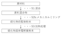
- FIG. 2 is a flow diagram showing one embodiment of the method for producing a sulfide solid electrolyte according to the present embodiment.
- FIG. 3 is a flow diagram showing one embodiment of the method for producing a sulfide solid electrolyte according to the present embodiment.
- Step S1 is a process of mixing raw materials to obtain a raw material mixture.
- Step S2 is a process for synthesizing at least one of a sulfide powder and a sulfide precursor powder from the raw material mixture obtained in step S1.
- Step S3 is a process of heat treating the powder obtained in step S2.
- step S2 preferably involves cooling a melt obtained by heating the raw material mixture to obtain a powder containing a sulfide powder, and more preferably involves cooling and pulverizing the melt to obtain a powder containing a sulfide powder.
- step S2 includes steps S2a-1 to S2a-3 as shown in FIG.
- Step S2a-1 is a process of heating and melting the raw material mixture obtained in step S1 to obtain a molten material.
- Step S2a-2 is a process of cooling the melt obtained in step S2a-1 to obtain a solid containing crystals.
- Step S2a-3 is a process of pulverizing the solid obtained in step S2a-2 to obtain a sulfide powder.
- step S2a-2 powder may be obtained while cooling the melt.
- step S2a-2 also serves as the crushing step S2a-3, so sulfide powder can be obtained without a separate crushing step in step S2a-3.
- the crystal structure is homogenized, and a sulfide solid electrolyte powder with stabilized quality is obtained.
- the homogenization and stabilization described above increases the lithium ion conductivity of the sulfide solid electrolyte powder, improving the battery performance when applied to a lithium ion secondary battery.
- step S2 preferably involves mechanical milling the raw material mixture to obtain a powder containing a sulfide precursor powder.
- step S2 preferably includes step S2b as shown in FIG.
- Step S2b is a process in which the raw material mixture obtained in step S1 is mechanically milled to obtain a sulfide precursor powder.
- the sulfide precursor powder obtained in step S2b is subjected to a heat treatment in step S3, whereby the sulfide precursor is sintered to form a sintered body, and a sulfide solid electrolyte powder is obtained.
- Step S1 raw materials are mixed to obtain a raw material mixture.
- a raw material mixture is obtained by mixing a raw material containing Li element, a raw material containing P element, and a raw material containing S element.
- a raw material containing a Li element, a raw material containing a P element, and a raw material containing a S element are further included, and a raw material containing a Ha element is further included.
- the Ha element is at least one element selected from the group consisting of F, Cl, Br, and I.
- the raw materials may contain other elements according to the composition of the desired sulfide solid electrolyte powder.
- the raw materials may contain the replaced other element.
- other elements include Si element, Al element, Sn element, In element, Cu element, Sb element, Ge element, and O element.
- the raw material containing Li As the raw material containing Li, the raw material containing P, the raw material containing S, and, if desired, the raw material containing Ha and the raw materials containing other elements, conventionally known raw materials can be used. Specifically, Li alone or a compound containing Li, P alone or a compound containing P, S alone or a compound containing S, or a compound containing Ha, etc., can be used in appropriate combination. When the sulfide solid electrolyte powder contains an O element, an oxide may be used as the compound. The compound may also be a compound containing Li, P, S, and optionally two or more other elements such as Ha.
- an example of a compound that serves both as a compound containing S and a compound containing P is diphosphorus pentasulfide (P 2 S 5 ).
- An example of a compound that serves both as a compound containing Li and a compound containing Ha is lithium halide.
- raw materials containing Li element include metallic lithium, as well as compounds containing Li, such as lithium compounds including lithium sulfide (Li 2 S), lithium carbonate (Li 2 CO 3 ), lithium sulfate (Li 2 SO 4 ), lithium oxide (Li 2 O), and lithium hydroxide (LiOH).
- the raw material containing Li element is preferably lithium sulfide from the viewpoint of ease of handling and reactivity.
- lithium sulfide is expensive, lithium compounds other than lithium sulfide, metallic lithium, etc. are preferable from the viewpoint of suppressing production costs.
- lithium carbonate Li 2 CO 3
- lithium sulfate Li 2 SO 4
- lithium oxide Li 2 O
- lithium hydroxide LiOH
- raw materials containing S element include elemental sulfur, as well as compounds containing S, such as phosphorus sulfides, such as diphosphorus trisulfide (P 2 S 3 ) and diphosphorus pentasulfide (P 2 S 5 ), other sulfur compounds containing phosphorus, and compounds containing sulfur.
- compounds containing sulfur include iron sulfides, such as H 2 S, CS 2 , FeS, Fe 2 S 3 , FeS 2 , and Fe 1-x S, and copper sulfides, such as bismuth sulfide (Bi 2 S 3 ), CuS, Cu 2 S, and Cu 1-x S.
- the raw material containing the S element is preferably phosphorus sulfide, more preferably diphosphorus pentasulfide (P 2 S 5 ) , from the viewpoint of reactivity and from the viewpoint of preventing the inclusion of elements other than the elements constituting the target sulfide solid electrolyte powder. These may be used alone or in combination of two or more.
- Phosphorus sulfide is a compound that serves as both a substance containing S and a substance containing P.
- raw materials containing the P element include elemental phosphorus, as well as compounds containing P, such as phosphorus sulfides such as diphosphorus trisulfide (P 2 S 3 ) and diphosphorus pentasulfide (P 2 S 5 ), and phosphorus compounds such as sodium phosphate (Na 3 PO 4 ) and lithium thiophosphate (Li 3 PS 4-x O x ).
- the raw material containing the P element is preferably phosphorus sulfide, more preferably diphosphorus pentasulfide (P 2 S 5 ) , from the viewpoint of ease of reaction when synthesizing an intermediate described later and preventing the inclusion of elements other than elements constituting the target sulfide solid electrolyte powder.
- the raw material containing P element contains an oxide
- examples thereof include P 2 O 5 , Li 3 PO 4 , and Li 4 P 2 O 7.
- P 2 O 5 is preferable.
- These compounds may be used alone or in combination of two or more kinds.
- examples of compounds containing Ha which are raw materials containing Ha element, include lithium halides such as lithium fluoride (LiF), lithium chloride (LiCl), lithium bromide (LiBr), and lithium iodide (LiI), phosphorus halides, phosphoryl halides, sulfur halides, sodium halides, and boron halides.
- the raw material containing the Ha element is preferably a lithium halide, more preferably LiCl, LiBr, or LiI. These compounds may be used alone or in combination of two or more.
- lithium halide is also a compound that contains Li.
- the raw material contains lithium halide, some or all of the Li in the raw material may be derived from the lithium halide.
- raw materials containing the other elements are also mixed to obtain a raw material mixture.
- raw materials containing Si element include, for example, SiO 2 and SiS 2. Among them, from the viewpoint of lithium ion conductivity and water resistance, SiO 2 is more preferable. These compounds may be used alone or in combination of two or more kinds.
- raw materials containing Al element as an optional component include Al 2 S 3 , Al 2 O 3 , and AlCl 3. Among them, from the viewpoint of lithium ion conductivity, Al 2 S 3 and AlCl 3 are preferable, and Al 2 S 3 is more preferable.
- These compounds may be used alone or in combination of two or more kinds.
- the raw material containing Sn element as an optional component include SnS, SnS 2 , SnO, SnO 2 , and SnCl 2. Among them, from the viewpoint of lithium ion conductivity, SnS 2 and SnCl 2 are preferable, and SnS 2 is more preferable.
- These compounds may be used alone or in combination of two or more kinds.
- Examples of raw materials containing an In element as an optional component include In 2 O 3 , In 2 S 3 , and InCl 3. Among them, from the viewpoint of lithium ion conductivity, In 2 S 3 and InCl 3 are preferable, and In 2 S 3 is more preferable.
- Examples of raw materials containing Cu element include Cu2O , CuO, Cu2S , CuS, and CuCl2 . Among them, from the viewpoint of lithium ion conductivity, CuS and CuCl2 are preferred, and CuS is more preferred. These compounds may be used alone or in combination of two or more.
- Examples of raw materials containing Sb element as an optional component include Sb 2 O 3 , Sb 2 S 3 , and SbCl 3. Among them, from the viewpoint of lithium ion conductivity, Sb 2 S 3 and SbCl 3 are preferable, and Sb 2 S 3 is more preferable. These compounds may be used alone or in combination of two or more kinds.
- examples of raw materials containing Ge element include GeO 2 , GeS, GeS 2 , and GeCl 2. Among them, from the viewpoint of lithium ion conductivity, GeS 2 and GeCl 2 are preferable, and GeS 2 is more preferable. These compounds may be used alone or in combination of two or more kinds.
- examples of raw materials containing B element as an optional component include B 2 S 3 , B 2 O 3 , and BCl 3. Among them, from the viewpoint of lithium ion conductivity, B 2 S 3 and BCl 3 are preferable, and B 2 S 3 is more preferable. These compounds may be used alone or in combination of two or more kinds.
- the raw materials can be mixed, for example, in a mortar, mixed using media such as a planetary ball mill, or mixed without media such as a pin mill, powder mixer, or airflow mixing.
- the subsequent step S2 involves mechanical milling in step S2b to convert the raw material mixture into a more uniform mixture, that is, a sulfide precursor powder, or to obtain a sulfide precursor powder that is an amorphous compound.
- a chemical reaction occurs, and the more energy is added, the more the bonding state of the elements changes.
- the mixing in step S1 refers to the degree of mixing in which multiple raw materials are placed in a single container, or the raw materials placed in the container are mixed using a mortar or stirring blades, etc., before being subjected to the above step S2b.
- Step S2 at least one of a sulfide powder and a sulfide precursor powder is synthesized from the raw material mixture obtained in step S2.
- a powder containing a sulfide powder is obtained.
- a sulfide solid electrolyte powder is produced by a solid-state reaction method, a powder containing a sulfide precursor powder is obtained.
- steps S2a-1 to S2a-3 are carried out as described above.
- step S2a-1 the raw material mixture obtained in step S1 is heated and melted to obtain a melt.
- the specific method for heating and melting the raw material mixture in step S2a-1 is not particularly limited, and the raw materials are placed in a heat-resistant container and heated in a heating furnace.
- the raw material mixture may also be sealed in a heat-resistant container.
- Melting may also be performed in an atmosphere containing elemental sulfur.
- an atmosphere containing elemental sulfur include a mixed gas atmosphere of a gas containing elemental sulfur, such as sulfur gas, hydrogen sulfide gas, or sulfur dioxide gas, and an inert gas.
- the heat-resistant container may be a heat-resistant container made of carbon, a heat-resistant container containing an oxide such as quartz, quartz glass, borosilicate glass, aluminosilicate glass, alumina, zirconia, or mullite, a heat-resistant container containing a nitride such as silicon nitride or boron nitride, or a heat-resistant container containing a carbide such as silicon carbide.
- These heat-resistant containers may be made of the above-mentioned materials in bulk, or may be a container with a layer of carbon, oxide, nitride, or carbide, such as a carbon-coated quartz tube.
- the heating temperature when the raw material mixture is heated and melted varies depending on the raw materials used and the composition of the raw material mixture, but is preferably 550 to 1000°C, more preferably 600 to 950°C, even more preferably 630 to 900°C, and particularly preferably 650 to 850°C.
- the heating temperature is preferably 550°C or higher, more preferably 600°C or higher, even more preferably 630°C or higher, and particularly preferably 650°C or higher, from the viewpoint of increasing the meltability of the raw materials and homogenizing the molten liquid in a short time.
- the heating temperature is preferably 1000°C or lower, more preferably 950°C or lower, even more preferably 900°C or lower, and particularly preferably 850°C or lower, from the viewpoint of suppressing deterioration of components due to heating, suppressing compositional deviation due to volatilization of components, and further suppressing decomposition.
- the heat melting time varies depending on the scale, but is preferably 10 minutes to 10 hours, more preferably 30 minutes to 9.5 hours, even more preferably 45 minutes to 9 hours, and particularly preferably 1 to 9 hours. From the viewpoint of smoothly progressing the reaction, the heat melting time is preferably 10 minutes or more, more preferably 30 minutes or more, even more preferably 45 minutes or more, and particularly preferably 1 hour or more. Also, from the viewpoint of productivity, the heat melting time is preferably 10 hours or less, more preferably 9.5 hours or less, and even more preferably 9 hours or less.
- the pressure during heating and melting is not particularly limited, but normal pressure or slight pressure is preferable, and normal pressure is more preferable.
- the dew point during heating and melting is preferably -20°C or lower, and although there is no particular lower limit, it is usually around -80°C.
- the oxygen concentration is preferably 1000 ppm by volume or less.
- step S2a-1 complete dissolution of the molten material can be confirmed by the absence of peaks derived from crystals in high-temperature X-ray diffraction measurement.
- step S2a-2 the melt obtained in step S2a-1 is cooled, crystals are precipitated, and a solid containing crystals is obtained.
- the solid obtained here is a sulfide compound containing crystals. This sulfide can also function as a solid electrolyte, but since it has not gone through the subsequent step S3, it is less homogeneous.
- Cooling may be performed by any known method, and the method is not particularly limited. More specific cooling methods include, for example, a method in which the molten material is poured onto a plate-like body made of carbon or the like and cooled; a method in which the molten material is poured into a narrow gap to form a thin film, such as the twin roll method; a method in which the molten material is sprayed and cooled in air; etc.
- the cooling rate is preferably 0.1 to 10,000 ° C./sec, more preferably 0.5 to 5,000 ° C./sec, and even more preferably 1 to 1,000 ° C./sec.
- the cooling rate is preferably 0.1 ° C./sec or more, more preferably 0.5 ° C./sec or more, and even more preferably 1 ° C./sec or more.
- the upper limit of the cooling rate is not particularly limited, but taking into account the cooling rate of the twin rollers, which is generally said to have the fastest quenching rate, the upper limit is 1,000,000 ° C./sec or less, and from the viewpoint of actual production, the cooling rate is more preferably 10,000 ° C./sec or less, more preferably 5,000 ° C./sec or less, and even more preferably 1,000 ° C./sec.
- the atmosphere during cooling is preferably an inert atmosphere with a low moisture content, similar to the heating and melting in step S2a-1.
- step S2a-3 the solid obtained in step S2a-2 is pulverized to obtain a sulfide powder.
- Either wet pulverization or dry pulverization may be used for the pulverization here.
- the average particle size refers to a median diameter (D50) which means a particle size at which 50 volume% of the particles are equal to or smaller than this value, and which is determined from a volume-based particle size distribution chart obtained by measuring the particle size distribution using a particle size distribution meter using a laser diffraction method.
- D50 median diameter
- Step S2a-3 does not need to be performed if the sulfide obtained in step S2a-2 is a powder with an average particle size of about 1 to 100 ⁇ m.
- step S2b the raw material mixture obtained in step S1 is mechanically milled to obtain a sulfide precursor powder, which is called synthesis.
- the mechanical milling include ball mills such as planetary ball mills, vibration mills, turbo mills, mechanofusion, and disk mills.
- the table rotation speed is preferably, for example, 100 to 500 rpm
- the processing time is preferably, for example, 1 to 100 hours, and more preferably 1 to 50 hours.
- the material or size of the container and grinding balls used in the planetary ball mill there are no particular restrictions on the material or size of the container and grinding balls used in the planetary ball mill, and conventionally known materials can be used. Examples of materials include alumina, zirconia, glass, silicon nitride, etc.
- the diameter of the grinding balls is, for example, 0.3 to 20 mm.
- Mechanical milling can be either dry or wet. When performing wet mechanical milling, it is preferable to use a dispersion medium that does not react with the raw materials to generate hydrogen sulfide, etc.
- wet mechanical milling it is preferable to dry the sulfide precursor powder before the subsequent step S3.
- drying method There are no particular limitations on the drying method, and examples include a method using an external heat drying oven or a hot air circulation drying oven.
- Sulfide precursor powders are different from powders of compounds that contain crystals that function as solid electrolytes, such as sulfide powders obtained by the melting method. They are powders of a mixture in which multiple raw materials are mixed very homogeneously, powders in which the chemical bonding state has changed from that of the starting materials due to a reaction, or powders of amorphous compounds.
- the average particle size of the sulfide powder or sulfide precursor powder obtained in step S2 for use in the subsequent step S3 is preferably 1 to 300 ⁇ m, more preferably 3 to 150 ⁇ m, and even more preferably 5 to 100 ⁇ m.
- the average particle size after grinding is preferably 1 ⁇ m or more, more preferably 3 ⁇ m or more, and even more preferably 5 ⁇ m or more.
- the average particle size after grinding is preferably 300 ⁇ m or less, more preferably 150 ⁇ m or less, and even more preferably 100 ⁇ m or less.
- Step S3 the powder obtained in step S2 is heat-treated.
- the sulfide powder obtained by the melting method is subjected to the heat treatment in step S3 to become a sulfide solid electrolyte powder with improved homogeneity and stabilized quality as a solid electrolyte, as described above.
- the sulfide precursor powder obtained by the solid-state reaction method is converted into a sulfide solid electrolyte powder, which is a powder of a sintered body, by the heat treatment in step S3.
- the reaction does not proceed any further.
- the synthesis reaction is a reaction between powders
- the formation of a heterogeneous interface causes the reaction to stop or proceed extremely slowly.
- the powder is pulverized as necessary, and then thermal energy is applied again, such as by a heat treatment, so that the particles become more homogeneous and a sulfide solid electrolyte powder with stable quality can be obtained.
- the heat treatment is carried out in an atmosphere with a SO2 concentration of 1 to 1000 ppm by volume, which makes it possible to suppress aggregation of the sulfide powder and the sulfide precursor powder.
- SO2 concentration 1 to 1000 ppm by volume
- the sulfur desorbed from the particle surface acts as a binder and binds the particles together, causing aggregation.
- the desorbed sulfur that promotes the aggregation reacts with oxygen in the gas to become SO2 , SOx , etc., and is removed as exhaust gas, reducing the sulfur that functions as a binder and suppressing aggregation.
- the above-mentioned effect is effective not only during the heat treatment for homogenization and stabilization in the melting method, but also during the heat treatment for firing carried out to synthesize a sulfide solid electrolyte in the solid-phase reaction method.
- the SO 2 concentration of 1 to 1000 ppm by volume in the atmosphere is the result of the reaction of the desorbed sulfur with oxygen, and the SO 2 concentration is preferably 2 to 500 ppm by volume, more preferably 3 to 100 ppm by volume.
- the SO 2 concentration is 1 ppm by volume or more, but from the viewpoint of further suppressing the aggregation of the powder, it is preferably 2 ppm by volume or more, and more preferably 3 ppm by volume or more.
- the SO 2 concentration is 1000 ppm by volume or less, but from the viewpoint of suppressing the oxidative decomposition of the electrolyte, it is preferably 500 ppm by volume or less, and more preferably 100 ppm by volume or less.
- the SO2 concentration can be adjusted by the amount of oxygen introduced during the heat treatment or the amount of oxygen brought in from the container.
- Oxygen may be introduced by flowing a gas containing oxygen element during heating and sintering, or may be introduced by oxygen originating from a container or other sources.
- oxygen derived from the container include a method of using a container that has not been pre-heated or has not been sufficiently pre-heated, or a method of using a porous container with a large specific surface area, whereas conventionally a container has been used from which adsorbed moisture and oxygen has been removed by pre-heating or the like.
- Other examples of oxygen that may be brought in include oxygen or water that is adsorbed onto the object to be heated.
- the present inventors have found that in addition to the SO2 concentration in the atmosphere during heat treatment, the agglomeration of powder can be mitigated or avoided by the shape of the container.
- the larger the production of sulfide solid electrolyte powder the greater the degree of crushing of the powder and gas penetration that affects the aggregation. That is, the larger the production scale, the greater the degree to which the powder is compressed by its own weight, and the closer the powder is to the bottom of the container, the denser the powder is and the more likely it is to aggregate.
- the sulfur that has been desorbed from the bottom of the container where the powder is dense is less likely to diffuse to the surroundings, and the sulfur that has accumulated at the bottom spreads throughout the bottom as if running along the bottom, making it easier to form a sulfur-rich layer, and as a result, the powder is more likely to aggregate.
- gas containing oxygen to react with the desorbed sulfur is less likely to penetrate into the interior of the dense powder aggregate, making it difficult to synthesize SO 2 or SO x . For these reasons, it is speculated that aggregation is more promoted when producing sulfide solid electrolyte powders on a large scale.
- the present inventors have found that the above-mentioned aggregation can be suitably suppressed by forming a container with a low height and a wide base.
- the relationship between a and b be 2a>b. It is more preferable that the relationship between a and b be 1.5a>b.
- examples of the bottom shape of the container other than a rectangle include circles including perfect circles and ellipses, and polygons.
- the long side of the bottom means the long side of a square or rectangle in which the circle is an inscribed circle.
- the long side of the bottom is the length of the longest side.
- the bottom shape is a polygon with pentagons or more sides, the long side of the bottom is the length of the longest diagonal.
- the surface roughness Ra of the container is preferably 0.1 to 30 ⁇ m, more preferably 0.4 to 10 ⁇ m, and even more preferably 0.8 to 8 ⁇ m.
- the surface roughness Ra is preferably 0.1 ⁇ m or more, more preferably 0.4 ⁇ m or more, and even more preferably 0.8 ⁇ m or more.
- the surface roughness Ra is preferably 30 ⁇ m or less, more preferably 10 ⁇ m or less, and even more preferably 8 ⁇ m or less.
- the surface roughness is determined as specified in JIS B 0601:2001 and refers to the center line average roughness.
- the porosity of the container refers to the open porosity.
- the open porosity refers to the value measured according to JIS R1634:1998.
- the porosity of the container is preferably 1% or more, and more preferably 1% to 50%. From the viewpoint of further suppressing aggregation, the porosity is preferably 1% or more, more preferably 5% or more, more preferably 10% or more, and even more preferably 15% or more.
- the upper limit of the porosity is not particularly limited as long as the powder does not fall off, but is, for example, 50% or less.
- the material of the container preferably contains at least one of aluminum and carbon as an element.
- its material may be carbon, alumina, mullite, silicon carbide, etc.
- its material may be a composite material such as alumina fiber or carbon fiber reinforced ceramic/resin, glass ceramic, alloy, etc.
- the container may contain at least one of aluminum and carbon as an element on its surface.
- ceramics containing at least one of aluminum and carbon as an element are more preferable, the material of which is further preferably carbon or alumina, and particularly preferably carbon.
- the wettability of the container and powder can be evaluated by placing sulfur powder on a material similar to the container, heating and melting the sulfur powder, and checking the contact angle. This is because it is believed that the compound that determines the above-mentioned wettability is sulfur.
- the heating temperature varies depending on the composition of the sulfide powder, i.e., the desired sulfide solid electrolyte, but is preferably 200 to 600°C, more preferably 350 to 500°C, even more preferably 380 to 460°C, and particularly preferably 400 to 450°C.
- the heating temperature is preferably 200°C or higher, more preferably 350°C or higher, even more preferably 380°C or higher, and particularly preferably 400°C or higher.
- the heating temperature is preferably 600°C or lower, more preferably 500°C or lower, even more preferably 460°C or lower, and particularly preferably 450°C or lower.
- the heating time varies depending on the composition of the sulfide powder, i.e., the desired sulfide solid electrolyte, but is preferably 10 minutes to 10 hours, more preferably 30 minutes to 9.5 hours, even more preferably 45 minutes to 9 hours, and particularly preferably 1 to 9 hours.
- the heating time is preferably 10 minutes or more, more preferably 30 minutes or more, even more preferably 45 minutes or more, and particularly preferably 1 hour or more.
- the heating time is preferably 10 hours or less, more preferably 9.5 hours or less, and even more preferably 9 hours or less.
- the atmosphere other than the SO2 concentration during the heat treatment is preferably an inert atmosphere.
- the inert atmosphere include a nitrogen gas atmosphere, an argon gas atmosphere, and a helium gas atmosphere.
- the dew point during the heat treatment is preferably ⁇ 20° C. or lower, and although there is no particular lower limit, it is usually about ⁇ 80° C.
- the oxygen concentration is preferably 1000 ppm by volume or lower.
- the above heating conditions can be used when the sulfide solid electrolyte has an argyrodite-type crystal structure, as well as when it has a crystal structure such as an LGPS-type crystal structure or a thiolisicone-type crystal structure.
- the heating temperature varies depending on the composition of the desired sulfide solid electrolyte, but is preferably 300 to 600°C, more preferably 350 to 575°C, and even more preferably 400 to 550°C. From the viewpoint of promoting crystallization, the heating temperature is preferably 300°C or higher, more preferably 350°C or higher, and even more preferably 400°C or higher. Also, from the viewpoint of suppressing thermal decomposition, the heating temperature is preferably 600°C or lower, more preferably 575°C or lower, and even more preferably 550°C or lower.
- the heat treatment time varies depending on the composition of the target sulfide solid electrolyte, but is preferably 0.1 to 100 hours, more preferably 0.3 to 50 hours, and even more preferably 0.5 to 24 hours. From the viewpoint of promoting crystallization, the heat treatment time is preferably 0.1 hours or more, more preferably 0.3 hours or more, and even more preferably 0.5 hours or more. From the viewpoint of production costs, the heat treatment time is preferably 100 hours or less, more preferably 50 hours or less, and even more preferably 24 hours or less.
- the atmosphere other than the SO2 concentration during the heat treatment is preferably an inert atmosphere.
- the inert atmosphere include a nitrogen gas atmosphere, an argon gas atmosphere, and a helium gas atmosphere.
- the dew point during the heat treatment is preferably ⁇ 20° C. or lower, and although there is no particular lower limit, it is usually about ⁇ 80° C.
- the oxygen concentration is preferably 1000 ppm by volume or lower.
- the above heating conditions can be used when the sulfide solid electrolyte has an argyrodite-type crystal structure, as well as when it has a crystal structure such as an LGPS-type crystal structure or a thiolisicone-type crystal structure.
- the sulfide solid electrolyte powder obtained through step S3 has a smaller difference in average particle size compared to the powder before being subjected to step S3. That is, the average particle size of the sulfide powder and sulfide precursor powder is preferably 1 to 300 ⁇ m, while the average particle size of the sulfide solid electrolyte powder is also preferably 1 to 300 ⁇ m.
- This allows the sulfide solid electrolyte to be immediately subjected to a fine pulverization process to produce a fine powder with an average particle size of several ⁇ m or less, which is necessary when actually applying the sulfide solid electrolyte to a lithium ion secondary battery. That is, there is no need for further pulverization before the above-mentioned pulverization. Furthermore, even if further pulverization is performed, pulverization can be performed more easily than in the past.
- the sulfide solid electrolyte powder preferably has a particle size of 100 ⁇ m or less of 90 mass% or more, more preferably 95 mass% or more, even more preferably 98 mass% or more, and particularly preferably 99 mass% or more.
- the above proportion is determined by a powder passage test using a 100 ⁇ m mesh pass. The test time for the powder passage test varies depending on the amount of powder and the size of the mesh pass, but 5 minutes or more is usually sufficient, and 10 minutes or more is preferable.
- the present invention also relates to a sulfide solid electrolyte powder obtained by the method described in the above [Method for producing a sulfide solid electrolyte].
- sulfide solid electrolytes having a crystal structure containing Li, P, and S elements which are called LPS-based electrolytes, such as Li 7 P 3 S 11
- LGPS-based electrolytes such as Li 10 GeP 2 S 12
- a sulfide solid electrolyte having a crystal structure containing Li, Ge, P, and S elements which is called the "sulfide solid electrolyte system”
- a sulfide solid electrolyte having an argyrodite-type crystal structure containing Li, P, S, and Ha elements which is called the "sulfide solid electrolyte system”
- the electrolyte may be a sulfide solid electrolyte made of Li-P-S-Ha type crystallized glass, or a sulfide solid electrolyte having a thiolisicone type crystal structure.
- the sulfide solid electrolyte may include an crystalline phase.
- the argyrodite-type crystal structure is a crystal structure possessed by a group of compounds derived from a mineral represented by the composition formula Ag 8 GeS 6.
- the sulfide solid electrolyte powder according to the present embodiment is not limited to the above crystal structure, and some elements may be substituted with other elements.
- the Ha element contains at least one element selected from the group consisting of Cl, Br, and I, and it is even more preferable that the Ha element contains two or more elements.
- the sulfide solid electrolyte according to this embodiment more preferably contains at least one of Cl and Br as the Ha element, and further preferably contains Cl and Br.
- the argyrodite-type crystal structure preferably has the above structure, and the composition formula is preferably represented by Li ⁇ PS ⁇ Ha ⁇ , and the relationships 5 ⁇ 7, 4 ⁇ 6, and 1.3 ⁇ 2 are satisfied.
- the element ratios more preferably satisfy the relationships 5.1 ⁇ 6.3, 4 ⁇ 5.3, and 1.4 ⁇ 1.9, and further preferably satisfy the relationships 5.2 ⁇ 6.2, 4.1 ⁇ 5.2, and 1.5 ⁇ 1.8. That is, ⁇ is preferably 5 or more, more preferably more than 5.1, and even more preferably more than 5.2, and is preferably 7 or less, more preferably less than 6.3, and even more preferably less than 6.2.
- ⁇ is preferably 4 or more, more preferably more than 4, and even more preferably more than 4.1, and is preferably 6 or less, more preferably less than 5.3, and even more preferably less than 5.2.
- ⁇ is preferably 1.3 or more, more preferably 1.4 or more, and even more preferably 1.5 or more, and is preferably 2 or less, more preferably 1.9 or less, and even more preferably 1.8 or less.
- a portion of the S element may be substituted with Ha element, O element, Se, Te, BH 4 , CN, etc.
- a portion of the P element may be substituted with Si element, Al element, Sn element, In element, Cu element, Sb element, Ge element, etc.
- the sulfide solid electrolyte powder according to this embodiment is made into a fine powder having an average particle size of about 0.1 to 2.0 ⁇ m by a fine pulverization process using a conventionally known method, and then pressure is applied together with a positive electrode active material or a negative electrode active material to form an electrode mixture, or pressure is applied together with an additive such as a binder as necessary to form a solid electrolyte layer, which is suitable for use in all-solid-state lithium secondary batteries.
- Example 1 Under a dry nitrogen gas atmosphere, lithium sulfide powder (manufactured by Sigma, purity 99.98%), diphosphorus pentasulfide powder (manufactured by Sigma, purity 99 %), lithium chloride powder (manufactured by Sigma, purity 99.99% ) , and lithium bromide powder (manufactured by Sigma, purity 99.995%) were weighed out so as to have a composition ratio of Li5.4PS4.4Cl0.8Br0.8, and mixed in a mortar to obtain a raw material mixture.
- the obtained raw material mixture was placed in a heat-resistant container and heated at 750°C for 60 minutes in an atmosphere of a gas containing elemental sulfur, to obtain a molten material in which the raw material mixture was heated and melted as a synthetic compound.
- the resulting molten material was then cooled to room temperature at a rate of 5° C./sec, pulverized in a mortar, and adjusted to an average particle size of 10 to 20 ⁇ m.
- the pulverized material was then passed through a 100 ⁇ m mesh to obtain a sulfide powder.
- 1 kg of the obtained sulfide powder was placed in a cylindrical container made of carbon with a bottom diameter of 150 mm and a height of 150 mm. Then, heat treatment was performed in an electric furnace at 400 ° C. for 1 hour under a dry nitrogen gas atmosphere.
- the SO2 concentration in the atmosphere was evaluated by the method described below.
- the sulfide solid electrolyte powder was then cooled again to room temperature at a rate of 1° C./sec to obtain a sulfide solid electrolyte powder containing argyrodite-type crystals. It was confirmed that the obtained sulfide solid electrolyte powder had a composition almost identical to the intended composition based on the diffraction pattern obtained by X-ray diffraction measurement and Rietveld analysis.
- Example 2 A sulfide solid electrolyte powder was obtained in the same manner as in Example 1, except that the obtained sulfide powder was placed in a cylindrical container made of alumina with a bottom diameter of 150 mm and a height of 150 mm, and that the atmosphere during the heat treatment was a dry nitrogen gas atmosphere into which oxygen gas was introduced at 10 ppm by volume.
- Example 3 A sulfide solid electrolyte powder was obtained in the same manner as in Example 1, except that the obtained sulfide powder was placed in a cylindrical container made of quartz, with a bottom diameter of 150 mm and a height of 150 mm.
- Example 4 A sulfide solid electrolyte powder was obtained in the same manner as in Example 1, except that the obtained sulfide powder was placed in a cylindrical container made of alumina, the diameter of the bottom being 100 mm and the height being 250 mm.
- Example 5 A sulfide solid electrolyte powder was obtained in the same manner as in Example 1, except that the obtained sulfide powder was placed in a cylindrical container made of carbon and having a bottom diameter of 100 mm and a height of 250 mm.
- Example 6 A sulfide solid electrolyte powder was obtained in the same manner as in Example 1, except that the obtained sulfide powder was placed in a cylindrical container made of alumina, with a bottom diameter of 150 mm and a height of 150 mm.
- Example 7 A lithium sulfide powder (manufactured by Sigma, purity 99.98 %), diphosphorus pentasulfide powder (manufactured by Sigma, purity 99%), and lithium chloride powder (manufactured by Sigma, purity 99.99%) were weighed out in a dry nitrogen gas atmosphere so as to have a composition ratio of Li5.4PS4.4Cl1.6, and mixed in a mortar to obtain a raw material mixture.
- the sulfide powder obtained was placed in a cylindrical container made of alumina with a bottom diameter of 150 mm and a height of 150 mm.
- a sulfide solid electrolyte powder was obtained in the same manner as in Example 1.
- Example 8 Under a dry nitrogen gas atmosphere, lithium sulfide powder (manufactured by Sigma, purity 99.98 % ), diphosphorus pentasulfide powder (manufactured by Sigma, purity 99%), and lithium chloride powder (manufactured by Sigma, purity 99.99%) were weighed out so as to have a composition ratio of Li5.4PS4.4Cl1.6, and mixed in a mortar to obtain a raw material mixture. The obtained raw material mixture was further mixed using a planetary ball mill (LP-M2, manufactured by Ito Seisakusho Co., Ltd.) to obtain a sulfide precursor. Mixing using the planetary ball mill was performed at 400 rpm for 20 hours using balls with a particle size of 10 mm.
- a planetary ball mill L-M2, manufactured by Ito Seisakusho Co., Ltd.
- the obtained sulfide precursor was pulverized using a mortar and adjusted to an average particle size of 10 to 20 ⁇ m, and then passed through a 100 ⁇ m mesh to obtain a sulfide precursor powder.
- 1 kg of the obtained sulfide precursor powder was placed in a cylindrical carbon container with a bottom diameter of 150 mm and a height of 150 mm.
- the sulfide precursor powder was then fired in an electric furnace at 400° C. for 5 hours in a dry nitrogen gas atmosphere, and then cooled to room temperature at a rate of 1° C./sec to obtain a sulfide solid electrolyte powder containing argyrodite-type crystals.
- Example 9 A sulfide solid electrolyte powder was obtained in the same manner as in Example 8, except that the atmosphere during the heat treatment of the obtained sulfide precursor powder was a dry nitrogen gas atmosphere into which 10 ppm by volume of oxygen gas was introduced.
- the results are shown in the "Wettability" section of Table 1, and the evaluation criteria are as follows: ⁇ : The contact angle is 50° or more, which means that the wettability is very low and very good. ⁇ : The contact angle is 25° or more and less than 50°, meaning that the wettability is low and good (passed). ⁇ : The contact angle is less than 25°, which means that the wettability is high and poor.
- a powder residue of 10 mass% or less is synonymous with a proportion of the particle diameter of 100 ⁇ m or less being 90 mass% or more. That is, it can be said that a powder residue of 10 mass% or less is good, more preferably 5 mass% or less, even more preferably 2 mass% or less, and particularly preferably 1 mass% or less.
- the SO 2 concentration during heat treatment is achieved by the reaction of the sulfur content desorbed from the sulfide powder or sulfide precursor powder with oxygen element, but it was found that the oxygen content adsorbed on the container is also effective as a source of oxygen element, in addition to actively introducing a small amount of oxygen gas. Furthermore, from a comparison of the results of Examples 1 and 5, and Examples 1 and 3, etc., it was found that the aggregation suppression effect is remarkable by appropriate container shape and wettability between the container and the sulfide powder or sulfide precursor powder.
Landscapes
- Chemical & Material Sciences (AREA)
- Engineering & Computer Science (AREA)
- Organic Chemistry (AREA)
- Inorganic Chemistry (AREA)
- Manufacturing & Machinery (AREA)
- Chemical Kinetics & Catalysis (AREA)
- Electrochemistry (AREA)
- General Chemical & Material Sciences (AREA)
- Physics & Mathematics (AREA)
- Materials Engineering (AREA)
- Condensed Matter Physics & Semiconductors (AREA)
- General Physics & Mathematics (AREA)
- Thermal Sciences (AREA)
- Secondary Cells (AREA)
- Conductive Materials (AREA)
Abstract
Description
従来、リチウムイオン二次電池においては液体の電解質が使用されてきた。一方で、安全性の向上や高速充放電、ケースの小型化等が期待できる点から、近年、固体電解質をリチウムイオン二次電池の電解質として用いる全固体型リチウムイオン二次電池が注目されている。
前記原料混合物から硫化物粉末及び硫化物前駆体粉末の少なくとも一方の粉末を合成すること、及び
前記粉末を加熱処理すること、を含み、
前記加熱処理は、SO2濃度が1~1000体積ppmの雰囲気で行う、硫化物固体電解質粉末の製造方法。
[2] 前記加熱処理の際に前記粉末を容器に入れ、
前記容器は、底面の長辺をa、高さをbとした際に、2a>bの関係を満たす、前記[1]に記載の硫化物固体電解質粉末の製造方法。
[3] 前記容器の表面粗さRaは0.1~30μmである、前記[2]に記載の硫化物固体電解質粉末の製造方法。
[4] 前記容器の材質は、元素としてアルミニウム及びカーボンの少なくとも一方を含む、前記[2]又は[3]に記載の硫化物固体電解質粉末の製造方法。
[5] 前記容器の気孔率は1%~50%である、前記[2]~[4]のいずれか1に記載の硫化物固体電解質粉末の製造方法。
[6] 前記粉末の平均粒子径は1~100μmである、前記[1]~[5]のいずれか1に記載の硫化物固体電解質粉末の製造方法。
[7] 前記合成において、前記原料混合物を加熱することにより得られた溶融物を冷却し、前記硫化物粉末を含む前記粉末を得る、前記[1]~[6]のいずれか1に記載の硫化物固体電解質粉末の製造方法。
[8] 前記合成において、前記原料混合物をメカニカルミリングすることで、前記硫化物前駆体粉末を含む粉末を得る、前記[1]~[7]のいずれか1に記載の硫化物固体電解質粉末の製造方法。
[9] 前記原材料は、Li元素、P元素、S元素、及びHa元素を含み、
得られる前記硫化物固体電解質粉末は、アルジロダイト型の結晶構造を有する、前記[1]~[8]のいずれか1に記載の硫化物固体電解質粉末の製造方法。
[10] 前記加熱処理は200~600℃の温度で行う、前記[9]に記載の硫化物固体電解質粉末の製造方法。
本実施形態に係る硫化物固体電解質粉末の製造方法(以下、「本製造方法」ともいう)は、図1に示すように、下記ステップS1~ステップS3を順に含む。
ステップS1は、原材料を混合して原料混合物を得る工程である。
ステップS2は、ステップS1で得られた原料混合物から、硫化物粉末及び硫化物前駆体粉末の少なくとも一方を合成する工程である。
ステップS3は、ステップS2で得られた粉末を加熱処理する工程である。
具体的には、ステップS2は、図2に示すように、ステップS2a-1~ステップS2a-3を含むことがさらに好ましい。
ステップS2a-2は、ステップS2a-1で得られた溶融物を冷却し、結晶を含む固体を得る工程である。
ステップS2a-3は、ステップS2a-2で得られた固体を粉砕して、硫化物粉末を得る工程である。
具体的には、ステップS2は図3に示すように、ステップS2bを含むことが好ましい。
ステップS1では、原材料を混合して原料混合物を得る。
得られる硫化物固体電解質粉末の組成によっても異なるが、例えば、Li元素を含む原材料、P元素を含む原材料、及びS元素を含む原材料を混合して原料混合物を得る。
アルジロダイト型の結晶構造を含む硫化物固体電解質粉末を得る場合には、Li元素を含む原材料、P元素を含む原材料、及びS元素を含む原材料に加え、さらにHa元素を含む原材料を含む。本明細書において、Ha元素とは、F、Cl、Br及びIからなる群より選ばれる少なくとも1種の元素である。
他の元素として、例えば、Si元素、Al元素、Sn元素、In元素、Cu元素、Sb元素、Ge元素、O元素等が挙げられる。
具体的には、Li単体やLiを含む化合物、P単体やPを含む化合物、及び、S単体やSを含む化合物や、任意でHaを含む化合物等を適宜組み合わせて使用できる。硫化物固体電解質粉末がO元素を含む場合には、上記化合物として酸化物を使用してもよい。また、上記化合物は、Li、P及びS、並びに、任意でHa等の他の元素の2以上を共に含む化合物であってもよい。例えば、Sを含む化合物及びPを含む化合物を兼ねる化合物として、五硫化二リン(P2S5)等が挙げられる。また、Liを含む化合物及びHaを含む化合物を兼ねる化合物として、ハロゲン化リチウムが挙げられる。
Li元素を含む原材料は、取り扱いやすさの観点や反応性の観点から硫化リチウムが好ましい。一方で、硫化リチウムは高価であるため、製造コストを抑える観点からは、硫化リチウム以外のリチウム化合物や、金属リチウム等が好ましい。具体的には、金属リチウム、炭酸リチウム(Li2CO3)、硫酸リチウム(Li2SO4)、酸化リチウム(Li2O)及び水酸化リチウム(LiOH)からなる群より選ばれる1種以上を用いることが好ましい。これらは単独で用いてもよく、2種以上を組み合わせて用いてもよい。
S元素を含む原材料は、反応性の観点や、目的の硫化物固体電解質粉末を構成する元素以外の元素の含有を防止する観点から、硫化リンが好ましく、五硫化二リン(P2S5)がより好ましい。これらは単独で用いてもよく、2種以上を組み合わせて用いてもよい。なお、硫化リンはSを含む物質とPを含む物質を兼ねる化合物である。
P元素を含む原材料は、後述する中間体を合成する際の反応のしやすさや、目的の硫化物固体電解質粉末を構成する元素以外の元素の含有を防止する観点から、硫化リンが好ましく、五硫化二リン(P2S5)がより好ましい。これらは単独で用いてもよく、2種以上を組み合わせて用いてもよい。
また、P元素を含む原材料として、酸化物を含有する場合には、例えば、P2O5、Li3PO4、Li4P2O7等が挙げられる。中でも、製造のし易さの観点からは、P2O5が好ましい。これらの化合物は単独で用いてもよく、2種以上を組合わせて用いてもよい。
Ha元素を含む原材料は、目的の硫化物固体電解質粉末を構成する元素以外の元素の含有を防止する観点からは、ハロゲン化リチウムが好ましく、LiCl、LiBr、LiIがより好ましい。これらの化合物は単独で用いてもよく、2種以上を組み合わせて用いてもよい。
任意成分として、Si元素を含む原材料としては、例えば、SiO2、SiS2が挙げられる。中でも、リチウムイオン伝導率と耐水性の観点からは、SiO2がより好ましい。これらの化合物は単独で用いてもよく、2種以上を組合わせて用いてもよい。
任意成分として、Al元素を含む原材料としては、例えば、Al2S3、Al2O3、AlCl3が挙げられる。中でも、リチウムイオン伝導率の観点からは、Al2S3、AlCl3が好ましく、Al2S3がより好ましい。これらの化合物は単独で用いてもよく、2種以上を組合わせて用いてもよい。
任意成分として、Sn元素を含む原材料としては、例えば、SnS、SnS2、SnO、SnO2、SnCl2が挙げられる。中でも、リチウムイオン伝導率の観点からは、SnS2、SnCl2が好ましく、SnS2がより好ましい。これらの化合物は単独で用いてもよく、2種以上を組合わせて用いてもよい。
任意成分として、In元素を含む原材料としては、例えば、In2O3、In2S3、InCl3が挙げられる。中でも、リチウムイオン伝導率の観点からは、In2S3、InCl3が好ましく、In2S3がより好ましい。これらの化合物は単独で用いてもよく、2種以上を組合わせて用いてもよい。
任意成分として、Cu元素を含む原材料としては、例えば、Cu2O、CuO、Cu2S、CuS、CuCl2が挙げられる。中でも、リチウムイオン伝導率の観点からは、CuS、CuCl2が好ましく、CuSがより好ましい。これらの化合物は単独で用いてもよく、2種以上を組合わせて用いてもよい。
任意成分として、Sb元素を含む原材料としては、例えば、Sb2O3、Sb2S3、SbCl3が挙げられる。中でも、リチウムイオン伝導率の観点からは、Sb2S3、SbCl3が好ましく、Sb2S3がより好ましい。これらの化合物は単独で用いてもよく、2種以上を組合わせて用いてもよい。
任意成分として、Ge元素を含む原材料としては、例えば、GeO2、GeS、GeS2、GeCl2が挙げられる。中でも、リチウムイオン伝導率の観点からは、GeS2、GeCl2が好ましく、GeS2がより好ましい。これらの化合物は単独で用いてもよく、2種以上を組合わせて用いてもよい。
任意成分として、B元素を含む原材料としては、例えば、B2S3、B2O3、BCl3が挙げられる。中でも、リチウムイオン伝導率の観点からは、B2S3、BCl3が好ましく、B2S3がより好ましい。これらの化合物は単独で用いてもよく、2種以上を組合わせて用いてもよい。
ステップS2では、ステップS2で得られた原料混合物から、硫化物粉末及び硫化物前駆体粉末の少なくとも一方を合成する。
溶融法により硫化物固体電解質粉末を製造する場合には、硫化物粉末を含む粉末が得られる。
固相反応法により硫化物固体電解質粉末を製造する場合には、硫化物前駆体粉末を含む粉末が得られる。
ステップS2a-1では、ステップS1で得られた原料混合物の加熱溶融を行い、溶融物を得る。
冷却時の雰囲気は、ステップS2a-1の加熱溶融時と同様に、低水分量、不活性雰囲気が好ましい。
ここで粉砕は湿式粉砕、乾式粉砕のいずれを用いてもよいが、後述する、固体電解質としてリチウムイオン二次電池に供するにあたって行われる微粉砕とは異なり、例えば、平均粒子径が1~300μmとなるまで粉砕することが好ましい。
なお、本明細書における平均粒子径とは、レーザー回折法を用いた粒度分布計を用いて粒度分布を測定し、得られた体積基準粒度分布のチャートから求められる、粒子の50体積%がその値以下の粒子径を意味するメジアン径(D50)をいう。
ステップS3では、ステップS2で得られた粉末を加熱処理する。
溶融法で得られた硫化物粉末は、ステップS3の加熱処理により、先述したように均質性を高め、固体電解質としての品質が安定化された硫化物固体電解質粉末となる。
固相反応法で得られた硫化物前駆体粉末は、ステップS3の加熱処理により、焼成された焼結体の粉末である硫化物固体電解質粉末となる。
これに対し、特に溶融法においては、原料混合物から硫化物粉末を得た後、必要に応じて粉砕を行った後、再度加熱処理といった熱エネルギーを与えることで、粒子がより均質になり、品質も安定した硫化物固体電解質粉末が得られるようになる。
この詳細は明らかではないが、先述したように、粒子表面より脱離した硫黄がバインダーの役目を果たし、粒子同士を繋ぐことで凝集が生じると考えている。そして、上記凝集を促進する脱離した硫黄が、気体中の酸素と反応してSO2やSOx等となり、排ガスとして除去されることで、バインダーとして機能する硫黄が減り、凝集が抑制されると考えられる。
上記効果は、溶融法における均質化、安定化のための加熱処理時のみならず、固相反応法において硫化物固体電解質を合成するために行う焼成である加熱処理時にも有効である。
酸素は、酸素元素を含むガスを加熱焼成時に流し込むことで導入してもよく、容器やその他持ち込み由来の酸素により導入してもよい。
容器由来の酸素とは、例えば、従来は空焼き等により吸着した水分や酸素を除去した容器を使用していたのに対し、空焼きをしてない容器や、十分に空焼きをしていない容器を用いる方法、比表面積が大きい多孔質の容器を用いる方法等が挙げられる。
その他持ち込み由来の酸素とは、例えば、加熱対象物に吸着する酸素や水を利用する方法等が挙げられる。
例えば、硫化物固体電解質粉末の製造を大量に行うほど、粉末の圧し潰しやガス浸透の程度が凝集に影響する。すなわち、製造スケールが大きいほど、自重により粉末が押し固められる程度が大きく、また、容器の底部に近い粉末であるほど、粉末が密になり、凝集されやすい。また、粉末が密になった容器の底部から脱離した硫黄が周囲に拡散しづらいことも関係して、底部に溜まった硫黄が、かかる底部をつたうように底部全体に濡れ拡がることで、硫黄リッチな層が形成されやすく、結果として、粉末が凝集しやすい。さらには脱離した硫黄と反応するための酸素を含むガスが、上記密になった粉末の集合体の内部まで浸透しづらく、SO2やSOxを合成しにくい。
これら理由により、硫化物固体電解質粉末の製造を大量に行う際には、凝集がより促進されるのではないかと推測している。
すなわち、加熱処理の際に粉末を入れる容器は、底面の長辺をa、高さをbとした際に、2a>bの関係を満たすことが好ましい。上記aとbとは、1.5a>bの関係を満たすことがより好ましい。
なお、容器の底面形状が矩形状以外の形状である場合として、例えば、真円及び楕円を含む円形や、多角形等が挙げられる。上記底面形状が円形の場合には、底面の長辺とは、当該円形が内接円となる正方形又は長方形の長辺を意味する。また、上記底面形状が三角形の場合には、最も長い辺の長さを、底面の長辺とする。上記底面形状が五角形以上の多角形である場合には、最も長い対角線の長さを、底面の長辺とする。
そこで、容器の表面粗さRaは0.1~30μmが好ましく、0.4~10μmがより好ましく、0.8~8μmがさらに好ましい。ここで、容器と粉末の濡れ性を低くし、より凝集を抑制する観点から、表面粗さRaは0.1μm以上が好ましく、0.4μm以上がより好ましく、0.8μm以上がさらに好ましい。また、上限は特に定めないが、使い易さの観点から、表面粗さRaは30μm以下が好ましく、10μm以下がより好ましく、8μm以下がさらに好ましい。表面粗さは、JIS B 0601:2001で規定されている通りに求め、中心線平均粗さのことを指す。
中でも、元素としてアルミニウム及びカーボンの少なくとも一方を含むセラミックがより好ましく、その材質はカーボン又はアルミナがさらに好ましく、カーボンが特に好ましい。
上記加熱処理時の露点は-20℃以下が好ましく、下限は特に制限されないが、通常-80℃程度である。酸素濃度は1000体積ppm以下が好ましい。
上記加熱処理時の露点は-20℃以下が好ましく、下限は特に制限されないが、通常-80℃程度である。酸素濃度は1000体積ppm以下が好ましい。
本発明は、上記〔硫化物固体電解質の製造方法〕に記載の方法で得られた硫化物固体電解質粉末にも関する。
具体的には、Li7P3S11等のようなLPS系と呼ばれるLi元素、P元素、及びS元素を含む結晶構造を有する硫化物固体電解質、Li10GeP2S12等のようなLGPS系と呼ばれるLi元素、Ge元素、P元素、及びS元素を含む結晶構造を有する硫化物固体電解質、Li元素、P元素、S元素、及びHa元素を含むアルジロダイト型の結晶構造を有する硫化物固体電解質、Li-P-S-Ha系の結晶化ガラスからなる硫化物固体電解質、チオリシコン型の結晶構造を有する硫化物固体電解質であってもよい。また、上記の結晶構造を有する結晶相と非晶質相とを含む硫化物固体電解質であってもよい。
また、本実施形態に係る硫化物固体電解質は、Ha元素として、Cl及びBrの少なくとも1種を含むことがさらに好ましく、Cl及びBrを含むこともさらに好ましい。
すなわち、αについて、5以上が好ましく、5.1超がより好ましく、5.2超がさらに好ましく、また、7以下が好ましく、6.3未満がより好ましく、6.2未満がさらに好ましい。βについて、4以上が好ましく、4超がより好ましく、4.1超がさらに好ましく、また、6以下が好ましく、5.3未満がより好ましく、5.2未満がさらに好ましい。γについて、1.3以上が好ましく、1.4以上がより好ましく、1.5以上がさらに好ましく、また、2以下が好ましく、1.9以下がより好ましく、1.8以下がさらに好ましい。
例1、例2、例5及び例7~例9が実施例であり、例3、例4及び例6が比較例である。
ドライ窒素ガス雰囲気下で、Li5.4PS4.4Cl0.8Br0.8の組成比となるように、硫化リチウム粉末(Sigma社製、純度99.98%)、五硫化二リン粉末(Sigma社製、純度99%)、塩化リチウム粉末(Sigma社製、純度99.99%)、及び臭化リチウム粉末(Sigma社製、純度99.995%)を秤量し、乳鉢で混合し、原料混合物を得た。
得られた原料混合物を、耐熱性容器に入れて、硫黄元素を含むガスの雰囲気下、750℃で60分加熱し、合成化合物として、原料混合物が加熱溶融された溶融物を得た。上記硫黄元素を含むガスは、硫黄ガス(Sx(x=2~8))と、キャリアガスとしてN2ガスと、を含む混合ガスを用い、混合ガス中の硫黄ガスの含有量は10体積%とした。
得られた硫化物粉末のうち1kgを、カーボン製であり、底部の直径が150mm、高さが150mmの円柱状の容器に入れた。その後、電気炉にて、ドライ窒素ガス雰囲気下、400℃で1時間加熱処理を行った。上記雰囲気中におけるSO2濃度については後述する方法で評価した。
そして、再度室温まで1℃/秒で冷却し、アルジロダイト型の結晶を含む硫化物固体電解質粉末を得た。得られた硫化物固体電解質粉末は、X線回折測定により得られた回折パターン及びリートベルト解析により、目的とした組成と殆ど同じ組成のものが得られていることを確認した。
得られた硫化物粉末を、アルミナ製であり、底部の直径が150mm、高さが150mmの円柱状の容器に入れた点、及び、加熱処理時の雰囲気をドライ窒素ガス雰囲気に対して、酸素ガスを10体積ppm導入した点以外は例1と同様にして、硫化物固体電解質粉末を得た。
得られた硫化物粉末を、石英製であり、底部の直径が150mm、高さが150mmの円柱状の容器に入れた点以外は例1と同様にして、硫化物固体電解質粉末を得た。
得られた硫化物粉末を、アルミナ製であり、底部の直径が100mm、高さが250mmの円柱状の容器に入れた以外は例1と同様にして、硫化物固体電解質粉末を得た。
得られた硫化物粉末を、カーボン製であり、底部の直径が100mm、高さが250mmの円柱状の容器に入れた以外は例1と同様にして、硫化物固体電解質粉末を得た。
得られた硫化物粉末を、アルミナ製であり、底部の直径が150mm、高さが150mmの円柱状の容器に入れた点以外は例1と同様にして、硫化物固体電解質粉末を得た。
ドライ窒素ガス雰囲気下で、Li5.4PS4.4Cl1.6の組成比となるように、硫化リチウム粉末(Sigma社製、純度99.98%)、五硫化二リン粉末(Sigma社製、純度99%)、及び塩化リチウム粉末(Sigma社製、純度99.99%を秤量し、乳鉢で混合し、原料混合物を得た点、及び、得られた硫化物粉末を、アルミナ製であり、底部の直径が150mm、高さが150mmの円柱状の容器に入れた点以外は例1と同様にして、硫化物固体電解質粉末を得た。
ドライ窒素ガス雰囲気下で、Li5.4PS4.4Cl1.6の組成比となるように、硫化リチウム粉末(Sigma社製、純度99.98%)、五硫化二リン粉末(Sigma社製、純度99%)、及び塩化リチウム粉末(Sigma社製、純度99.99%を秤量し、乳鉢で混合し、原料混合物を得た。
得られた原料混合物を、遊星ボールミル(伊藤製作所社製、LP-M2)を用いてさらに混合することで、硫化物前駆体を得た。遊星ボールミルによる混合は、粒径10mmのボールを用いて、400rpmで20時間行った。得られた硫化物前駆体は、乳鉢を用いて粉砕し、平均粒子径が10~20μmとなるように調整した後、100μmメッシュパスし、硫化物前駆体粉末を得た。
得られた硫化物前駆体粉末のうち1kgを、カーボン製であり、底部の直径が150mm、高さが150mmの円柱状の容器に入れた。その後、電気炉にて、ドライ窒素ガス雰囲気下、400℃で5時間加熱処理を行うことで焼成し、次いで室温まで1℃/秒で冷却することにより、アルジロダイト型の結晶を含む硫化物固体電解質粉末を得た。
得られた硫化物前駆体粉末の加熱処理時の雰囲気をドライ窒素ガス雰囲気に対して、酸素ガスを10体積ppm導入した点以外は例8と同様にして、硫化物固体電解質粉末を得た。
例1~例9において、硫化物粉末又は硫化物前駆体粉末と容器との濡れ性を、硫黄粉末を容器と同様の材質上に乗せ、硫黄粉末を溶かしてその接触角を確認することにより評価した。これは、上記濡れ性を左右する化合物は硫黄だと考えられるためである。
具体的には、各容器と同じ材質でできた板の上に、硫黄粉末30mgを乗せ、150℃で融解して接触角を調べた。冷却して得た液滴を横からカメラを用いて撮影し、上記板となす接触角を求めた。
結果を表1の「濡れ性」の項目に示すが、評価基準は下記のとおりである。
○:接触角が50°以上であり、濡れ性が非常に低く、非常に良好であることを意味する。
△:接触角が25°以上50°未満であり、濡れ性が低く、良好(合格)であることを意味する。
×:接触角が25°未満であり、濡れ性が高く、不良であることを意味する。
例1~例9において、加熱処理時の雰囲気中におけるSO2濃度を、排出ガスに対して、検知管(二酸化硫黄No.5La、GASTEC社製)を用いて測定することにより求めた。測定は、電気炉内の温度が目標加熱処理温度に到達した直後に行った。
結果を表1の「SO2濃度」の項目に示す。
例1~例9で得られた硫化物固体電解質粉末のうち100gを、自動振動篩機(Retsch社製、電磁式ふるい振とう機AS200 ベーシック)を用いて、100μmメッシュパスを行った。メッシュパスした時間は10分とした。メッシュ上に残った粉体の割合を表1の「凝集性」の「粉体残分」に示す。
上記粉体残分とは、硫化物固体電解質粉末の粒子径が100μm以下の割合と関連する。すなわち、上記粉体残分とは、硫化物固体電解質粉末の粒子径が100μm超の割合を意味する。具体的には、粉体残分が10質量%以下であることは、上記粒子径が100μm以下の割合が90質量%以上であることと同義である。すなわち、粉体残分は10質量%以下であれば良好であると言え、5質量%以下がより好ましく、2質量%以下がさらに好ましく、1質量%以下が特に好ましい。
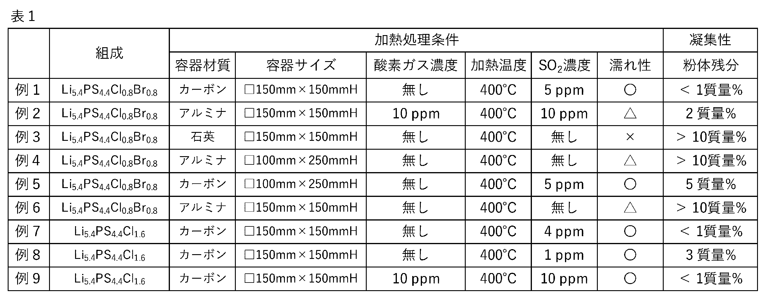
加熱処理時のSO2濃度は、硫化物粉末又は硫化物前駆体粉末から脱離した硫黄分が酸素元素と反応することにより達成されるが、この酸素元素源として、積極的に酸素ガスを微量導入する他、容器に吸着している酸素分も効果的であることが分かった。さらに、例1と例5、例1と例3等の結果の対比から、容器形状や、容器と硫化物粉末又は硫化物前駆体粉末の濡れ性を適切なものとすることで、凝集抑制効果は顕著になることが分かった。
Claims (10)
- 原材料を混合して原料混合物を得ること、
前記原料混合物から硫化物粉末及び硫化物前駆体粉末の少なくとも一方の粉末を合成すること、及び
前記粉末を加熱処理すること、を含み、
前記加熱処理は、SO2濃度が1~1000体積ppmの雰囲気で行う、硫化物固体電解質粉末の製造方法。 - 前記加熱処理の際に前記粉末を容器に入れ、
前記容器は、底面の長辺をa、高さをbとした際に、2a>bの関係を満たす、請求項1に記載の硫化物固体電解質粉末の製造方法。 - 前記容器の表面粗さRaは0.1~30μmである、請求項2に記載の硫化物固体電解質粉末の製造方法。
- 前記容器の材質は、元素としてアルミニウム及びカーボンの少なくとも一方を含む、請求項2に記載の硫化物固体電解質粉末の製造方法。
- 前記容器の気孔率は1%~50%である、請求項2に記載の硫化物固体電解質粉末の製造方法。
- 前記粉末の平均粒子径は1~100μmである、請求項1又は2に記載の硫化物固体電解質粉末の製造方法。
- 前記合成において、前記原料混合物を加熱することにより得られた溶融物を冷却し、前記硫化物粉末を含む前記粉末を得る、請求項1又は2に記載の硫化物固体電解質粉末の製造方法。
- 前記合成において、前記原料混合物をメカニカルミリングすることで、前記硫化物前駆体粉末を含む粉末を得る、請求項1又は2に記載の硫化物固体電解質粉末の製造方法。
- 前記原材料は、Li元素、P元素、S元素、及びHa元素を含み、
得られる前記硫化物固体電解質粉末は、アルジロダイト型の結晶構造を有する、請求項1又は2に記載の硫化物固体電解質粉末の製造方法。 - 前記加熱処理は200~600℃の温度で行う、請求項9に記載の硫化物固体電解質粉末の製造方法。
Priority Applications (5)
| Application Number | Priority Date | Filing Date | Title |
|---|---|---|---|
| JP2024573073A JPWO2024157974A1 (ja) | 2023-01-27 | 2024-01-23 | |
| CN202480009142.6A CN120642003A (zh) | 2023-01-27 | 2024-01-23 | 硫化物固体电解质粉末的制造方法 |
| EP24747301.0A EP4657468A1 (en) | 2023-01-27 | 2024-01-23 | Method for producing sulfide solid electrolyte powder |
| KR1020257025103A KR20250139289A (ko) | 2023-01-27 | 2024-01-23 | 황화물 고체 전해질 분말의 제조 방법 |
| US19/279,432 US20250349887A1 (en) | 2023-01-27 | 2025-07-24 | Method for producing sulfide solid electrolyte powder |
Applications Claiming Priority (2)
| Application Number | Priority Date | Filing Date | Title |
|---|---|---|---|
| JP2023011196 | 2023-01-27 | ||
| JP2023-011196 | 2023-01-27 |
Related Child Applications (1)
| Application Number | Title | Priority Date | Filing Date |
|---|---|---|---|
| US19/279,432 Continuation US20250349887A1 (en) | 2023-01-27 | 2025-07-24 | Method for producing sulfide solid electrolyte powder |
Publications (1)
| Publication Number | Publication Date |
|---|---|
| WO2024157974A1 true WO2024157974A1 (ja) | 2024-08-02 |
Family
ID=91970605
Family Applications (1)
| Application Number | Title | Priority Date | Filing Date |
|---|---|---|---|
| PCT/JP2024/001852 Ceased WO2024157974A1 (ja) | 2023-01-27 | 2024-01-23 | 硫化物固体電解質粉末の製造方法 |
Country Status (6)
| Country | Link |
|---|---|
| US (1) | US20250349887A1 (ja) |
| EP (1) | EP4657468A1 (ja) |
| JP (1) | JPWO2024157974A1 (ja) |
| KR (1) | KR20250139289A (ja) |
| CN (1) | CN120642003A (ja) |
| WO (1) | WO2024157974A1 (ja) |
Citations (5)
| Publication number | Priority date | Publication date | Assignee | Title |
|---|---|---|---|---|
| WO2015012042A1 (ja) | 2013-07-25 | 2015-01-29 | 三井金属鉱業株式会社 | リチウムイオン電池用硫化物系固体電解質 |
| WO2018047565A1 (ja) | 2016-09-12 | 2018-03-15 | 出光興産株式会社 | 硫化物固体電解質 |
| CN110311168A (zh) * | 2019-06-19 | 2019-10-08 | 浙江锋锂新能源科技有限公司 | 一种硫化物固体电解质及其制备方法和全固态电池 |
| JP2022134454A (ja) * | 2021-03-03 | 2022-09-15 | 三菱マテリアル株式会社 | 硫化リチウムの製造方法 |
| JP2023011196A (ja) | 2021-07-12 | 2023-01-24 | 河村電器産業株式会社 | 感震装置、建物診断装置、感震プログラム、建物診断プログラム、感震方法及び建物診断方法 |
-
2024
- 2024-01-23 KR KR1020257025103A patent/KR20250139289A/ko active Pending
- 2024-01-23 CN CN202480009142.6A patent/CN120642003A/zh active Pending
- 2024-01-23 EP EP24747301.0A patent/EP4657468A1/en active Pending
- 2024-01-23 JP JP2024573073A patent/JPWO2024157974A1/ja active Pending
- 2024-01-23 WO PCT/JP2024/001852 patent/WO2024157974A1/ja not_active Ceased
-
2025
- 2025-07-24 US US19/279,432 patent/US20250349887A1/en active Pending
Patent Citations (5)
| Publication number | Priority date | Publication date | Assignee | Title |
|---|---|---|---|---|
| WO2015012042A1 (ja) | 2013-07-25 | 2015-01-29 | 三井金属鉱業株式会社 | リチウムイオン電池用硫化物系固体電解質 |
| WO2018047565A1 (ja) | 2016-09-12 | 2018-03-15 | 出光興産株式会社 | 硫化物固体電解質 |
| CN110311168A (zh) * | 2019-06-19 | 2019-10-08 | 浙江锋锂新能源科技有限公司 | 一种硫化物固体电解质及其制备方法和全固态电池 |
| JP2022134454A (ja) * | 2021-03-03 | 2022-09-15 | 三菱マテリアル株式会社 | 硫化リチウムの製造方法 |
| JP2023011196A (ja) | 2021-07-12 | 2023-01-24 | 河村電器産業株式会社 | 感震装置、建物診断装置、感震プログラム、建物診断プログラム、感震方法及び建物診断方法 |
Non-Patent Citations (1)
| Title |
|---|
| See also references of EP4657468A1 |
Also Published As
| Publication number | Publication date |
|---|---|
| US20250349887A1 (en) | 2025-11-13 |
| CN120642003A (zh) | 2025-09-12 |
| KR20250139289A (ko) | 2025-09-23 |
| JPWO2024157974A1 (ja) | 2024-08-02 |
| EP4657468A1 (en) | 2025-12-03 |
Similar Documents
| Publication | Publication Date | Title |
|---|---|---|
| US20240055653A1 (en) | Sulfide based solid electrolyte, solid electrolyte layer, and lithium ion secondary battery | |
| WO2023145657A1 (ja) | 硫化物系固体電解質の製造方法 | |
| WO2023053610A1 (ja) | 硫化物系固体電解質 | |
| JP7537654B1 (ja) | 硫化物固体電解質の製造方法 | |
| WO2024157974A1 (ja) | 硫化物固体電解質粉末の製造方法 | |
| JP7677479B2 (ja) | アルカリ金属元素及び硫黄元素を含む物質の製造方法 | |
| WO2024181099A1 (ja) | 水酸化リチウムの製造方法、リチウムを含む硫化物固体電解質原料の製造方法、及び硫化物固体電解質の製造方法 | |
| WO2024018976A1 (ja) | 硫化物固体電解質及びその製造方法 | |
| WO2024014382A1 (ja) | 硫化物系固体電解質及びその製造方法、電極合剤、固体電解質層、並びに、全固体リチウムイオン二次電池 | |
| WO2023053611A1 (ja) | 硫化物系固体電解質とその製造方法 | |
| US20250372703A1 (en) | Method for producing sulfide solid electrolyte composite, sulfide solid electrolyte composite, and method for producing composite powder | |
| WO2025069784A1 (ja) | 硫化物固体電解質及びその製造方法 | |
| US20250349888A1 (en) | Method for producing sulfide solid electrolyte powder and apparatus for producing sulfide solid electrolyte powder | |
| US20250316754A1 (en) | Method for producing sulfide solid electrolyte complex, sulfide solid electrolyte complex, and method for producing complex powder | |
| WO2025069783A1 (ja) | 硫化物固体電解質及びその製造方法 | |
| WO2025069786A1 (ja) | ガラス、結晶化ガラス、硫化物固体電解質、電極合剤、固体電解質層、及びリチウムイオン二次電池 | |
| WO2024143266A1 (ja) | 硫化物固体電解質の原材料に用いられる複合体粉末及びその製造方法、並びに、硫化物固体電解質の製造方法 | |
| WO2025069782A1 (ja) | 硫化物固体電解質及びその製造方法、並びに、リチウムイオン伝導性結晶体 | |
| WO2025069780A1 (ja) | 硫化物固体電解質 | |
| WO2025023042A1 (ja) | 硫化物固体電解質の製造方法 | |
| WO2025121290A1 (ja) | 硫化物固体電解質及びその製造方法 | |
| WO2025023039A1 (ja) | 硫化物固体電解質原料の混合物および硫化物固体電解質の製造方法 | |
| WO2025249248A1 (ja) | 硫化物固体電解質及び硫化物固体電解質の製造方法 | |
| WO2025121293A1 (ja) | 硫化物固体電解質及びその製造方法 | |
| WO2025013675A1 (ja) | 硫化物固体電解質の製造方法および再利用方法 |
Legal Events
| Date | Code | Title | Description |
|---|---|---|---|
| 121 | Ep: the epo has been informed by wipo that ep was designated in this application |
Ref document number: 24747301 Country of ref document: EP Kind code of ref document: A1 |
|
| ENP | Entry into the national phase |
Ref document number: 2024573073 Country of ref document: JP Kind code of ref document: A |
|
| WWE | Wipo information: entry into national phase |
Ref document number: 2024573073 Country of ref document: JP |
|
| WWE | Wipo information: entry into national phase |
Ref document number: 202480009142.6 Country of ref document: CN |
|
| ENP | Entry into the national phase |
Ref document number: 1020257025103 Country of ref document: KR Free format text: ST27 STATUS EVENT CODE: A-0-1-A10-A15-NAP-PA0105 (AS PROVIDED BY THE NATIONAL OFFICE) |
|
| NENP | Non-entry into the national phase |
Ref country code: DE |
|
| WWP | Wipo information: published in national office |
Ref document number: 202480009142.6 Country of ref document: CN |
|
| WWP | Wipo information: published in national office |
Ref document number: 2024747301 Country of ref document: EP |