WO2024161939A1 - 二次電池 - Google Patents
二次電池 Download PDFInfo
- Publication number
- WO2024161939A1 WO2024161939A1 PCT/JP2024/000509 JP2024000509W WO2024161939A1 WO 2024161939 A1 WO2024161939 A1 WO 2024161939A1 JP 2024000509 W JP2024000509 W JP 2024000509W WO 2024161939 A1 WO2024161939 A1 WO 2024161939A1
- Authority
- WO
- WIPO (PCT)
- Prior art keywords
- negative electrode
- positive electrode
- current collector
- silicon
- mixture layer
- Prior art date
- Legal status (The legal status is an assumption and is not a legal conclusion. Google has not performed a legal analysis and makes no representation as to the accuracy of the status listed.)
- Ceased
Links
Images


Classifications
-
- H—ELECTRICITY
- H01—ELECTRIC ELEMENTS
- H01M—PROCESSES OR MEANS, e.g. BATTERIES, FOR THE DIRECT CONVERSION OF CHEMICAL ENERGY INTO ELECTRICAL ENERGY
- H01M10/00—Secondary cells; Manufacture thereof
- H01M10/04—Construction or manufacture in general
- H01M10/0431—Cells with wound or folded electrodes
-
- H—ELECTRICITY
- H01—ELECTRIC ELEMENTS
- H01M—PROCESSES OR MEANS, e.g. BATTERIES, FOR THE DIRECT CONVERSION OF CHEMICAL ENERGY INTO ELECTRICAL ENERGY
- H01M4/00—Electrodes
- H01M4/02—Electrodes composed of, or comprising, active material
- H01M4/36—Selection of substances as active materials, active masses, active liquids
- H01M4/362—Composites
-
- H—ELECTRICITY
- H01—ELECTRIC ELEMENTS
- H01M—PROCESSES OR MEANS, e.g. BATTERIES, FOR THE DIRECT CONVERSION OF CHEMICAL ENERGY INTO ELECTRICAL ENERGY
- H01M4/00—Electrodes
- H01M4/02—Electrodes composed of, or comprising, active material
- H01M4/36—Selection of substances as active materials, active masses, active liquids
- H01M4/38—Selection of substances as active materials, active masses, active liquids of elements or alloys
- H01M4/386—Silicon or alloys based on silicon
-
- H—ELECTRICITY
- H01—ELECTRIC ELEMENTS
- H01M—PROCESSES OR MEANS, e.g. BATTERIES, FOR THE DIRECT CONVERSION OF CHEMICAL ENERGY INTO ELECTRICAL ENERGY
- H01M50/00—Constructional details or processes of manufacture of the non-active parts of electrochemical cells other than fuel cells, e.g. hybrid cells
- H01M50/10—Primary casings; Jackets or wrappings
- H01M50/102—Primary casings; Jackets or wrappings characterised by their shape or physical structure
- H01M50/107—Primary casings; Jackets or wrappings characterised by their shape or physical structure having curved cross-section, e.g. round or elliptic
-
- H—ELECTRICITY
- H01—ELECTRIC ELEMENTS
- H01M—PROCESSES OR MEANS, e.g. BATTERIES, FOR THE DIRECT CONVERSION OF CHEMICAL ENERGY INTO ELECTRICAL ENERGY
- H01M4/00—Electrodes
- H01M4/02—Electrodes composed of, or comprising, active material
- H01M2004/026—Electrodes composed of, or comprising, active material characterised by the polarity
- H01M2004/027—Negative electrodes
-
- Y—GENERAL TAGGING OF NEW TECHNOLOGICAL DEVELOPMENTS; GENERAL TAGGING OF CROSS-SECTIONAL TECHNOLOGIES SPANNING OVER SEVERAL SECTIONS OF THE IPC; TECHNICAL SUBJECTS COVERED BY FORMER USPC CROSS-REFERENCE ART COLLECTIONS [XRACs] AND DIGESTS
- Y02—TECHNOLOGIES OR APPLICATIONS FOR MITIGATION OR ADAPTATION AGAINST CLIMATE CHANGE
- Y02E—REDUCTION OF GREENHOUSE GAS [GHG] EMISSIONS, RELATED TO ENERGY GENERATION, TRANSMISSION OR DISTRIBUTION
- Y02E60/00—Enabling technologies; Technologies with a potential or indirect contribution to GHG emissions mitigation
- Y02E60/10—Energy storage using batteries
-
- Y—GENERAL TAGGING OF NEW TECHNOLOGICAL DEVELOPMENTS; GENERAL TAGGING OF CROSS-SECTIONAL TECHNOLOGIES SPANNING OVER SEVERAL SECTIONS OF THE IPC; TECHNICAL SUBJECTS COVERED BY FORMER USPC CROSS-REFERENCE ART COLLECTIONS [XRACs] AND DIGESTS
- Y02—TECHNOLOGIES OR APPLICATIONS FOR MITIGATION OR ADAPTATION AGAINST CLIMATE CHANGE
- Y02P—CLIMATE CHANGE MITIGATION TECHNOLOGIES IN THE PRODUCTION OR PROCESSING OF GOODS
- Y02P70/00—Climate change mitigation technologies in the production process for final industrial or consumer products
- Y02P70/50—Manufacturing or production processes characterised by the final manufactured product
Definitions
- This disclosure relates to secondary batteries.
- Patent document 1 describes a battery comprising: "a positive electrode having a positive electrode core material and a positive electrode material layer supported on the positive electrode core material; a negative electrode having a negative electrode core material and a negative electrode material layer supported on the negative electrode core material; a separator interposed between the positive electrode and the negative electrode; a non-aqueous electrolyte; a positive electrode current collector electrically connected to the positive electrode core material; and a negative electrode current collector electrically connected to the negative electrode core material; the positive electrode, the negative electrode, and the separator form a columnar wound body.
- An electrochemical device having a positive electrode core material exposed portion at an end along the longitudinal direction of the positive electrode core material, a negative electrode core material exposed portion at an end along the longitudinal direction of the negative electrode core material, the positive electrode core material exposed portion protruding from one end face of the wound body and welded to the positive electrode current collector plate, the negative electrode core material exposed portion protruding from the other end face of the wound body and welded to the negative electrode current collector plate, and the thickness of the positive electrode core material is greater than the thickness of the negative electrode core material.
- Patent Document 1 Unlike Patent Document 1, if there is an exposed portion of the positive electrode current collector that does not have a positive electrode mixture layer on part of the edge of the positive electrode, the stress applied to one end of the negative electrode in the short direction due to charging and discharging the secondary battery is lower. This can cause gaps to form between the plates near the end faces of the electrode group formed by winding the positive electrode, negative electrode, and separator. Such gaps may induce peeling of the negative electrode mixture layer or precipitation of metallic lithium.
- One aspect of the present disclosure is a battery comprising a positive electrode, a negative electrode, an electrolyte, and a separator, the positive electrode and the negative electrode being wound with the separator interposed therebetween, the positive electrode comprising a strip-shaped positive electrode collector and a positive electrode mixture layer disposed on the positive electrode collector, the positive electrode having a positive electrode edge portion including one end of the positive electrode in the short direction and a positive electrode main portion other than the positive electrode edge portion, the positive electrode edge portion being spaced apart along the longitudinal direction of the positive electrode collector
- the secondary battery has an exposed portion of the positive electrode current collector that is provided at multiple locations, and the exposed portion does not have the positive electrode mixture layer from the one end in the short direction to the positive electrode main portion, and the negative electrode has a strip-shaped negative electrode current collector, and the negative electrode has a negative electrode edge portion that faces at least a part of the positive electrode edge portion and a negative electrode main portion other than the negative electrode edge portion, and the expansion rate of the negative electrode mixture layer of the negative electrode edge portion is
- FIG. 1 is a schematic cross-sectional view of a secondary battery according to an embodiment
- FIG. 2 is a schematic plan view of a positive electrode according to an embodiment.
- FIG. 2 is a schematic plan view of a negative electrode according to an embodiment.
- Secondary batteries include non-aqueous electrolyte secondary batteries such as lithium ion secondary batteries, lithium metal secondary batteries, and solid-state batteries containing a gel electrolyte or a solid electrolyte.
- the secondary battery may be a liquid secondary battery containing an electrolytic solution as an electrolyte, or an all-solid-state secondary battery containing a solid electrolyte.
- the secondary battery according to the present disclosure comprises a strip-shaped positive electrode, a strip-shaped negative electrode, an electrolyte, and a separator disposed between the positive electrode and the negative electrode.
- the positive electrode and the negative electrode are wound (wound) with the separator interposed therebetween.
- the secondary battery comprises a wound electrode group.
- the outer shape of the wound electrode group is columnar, and may be, for example, cylindrical.
- the positive electrode includes a strip-shaped positive electrode current collector and a positive electrode mixture layer disposed on the positive electrode current collector.
- the positive electrode mixture layer may be in the form of a film.
- the positive electrode includes a positive electrode current collector and a positive electrode mixture layer formed (or supported) on a partial region of the surface of the positive electrode current collector.
- the positive electrode includes a positive electrode edge portion including one end in the short side direction of the positive electrode, and a positive electrode main portion other than the positive electrode edge portion.
- the positive electrode edge portion includes an exposed portion of the positive electrode current collector that is intermittently provided at a plurality of locations along the longitudinal direction of the positive electrode current collector.
- the exposed portion of the positive electrode current collector does not include a positive electrode mixture layer from one end in the short side direction to the positive electrode main portion.
- the positive electrode mixture layer is composed of a positive electrode mixture. Since the positive electrode mixture contains a positive electrode active material as an essential component, the positive electrode mixture layer may also be called a positive electrode active material layer. The positive electrode mixture layer is supported on one or both surfaces of the positive electrode current collector.
- the positive electrode mixture contains a positive electrode active material as an essential component, and may contain optional components such as a binder, a conductive assistant, and a thickener.
- the positive electrode active material may be a material that reversibly absorbs and releases lithium ions.
- the positive electrode active material may be, for example, a lithium-containing transition metal oxide.
- Representative examples of lithium-containing transition metal oxides include lithium cobalt oxide and lithium nickel oxide, which have a layered, rock-salt crystal structure.
- the positive electrode mixture layer can be formed, for example, by applying a positive electrode slurry, in which a positive electrode mixture containing particles of the essential component positive electrode active material and optional components (binder, conductive additive, etc.) is dispersed in a dispersion medium, to the surface of the positive electrode current collector and then drying. The coating film after drying may be rolled as necessary.
- the positive electrode mixture layer may be formed on one surface or both surfaces of the positive electrode current collector. N-methyl-2-pyrrolidone (NMP) or the like is used as the dispersion medium for the positive electrode slurry.
- NMP N-methyl-2-pyrrolidone
- a composite oxide containing lithium and a transition metal such as Ni, Co, or Mn can be used.
- examples include Li a CoO 2 , Li a NiO 2 , Li a MnO 2 , Li a Co b Ni 1-b O 2 , Li a Co b M 1-b O c , Li a Ni 1-b M b O c , Li a Mn 2 O 4 , Li a Mn 2-b M b O 4 , LiMPO 4 , and Li 2 MPO 4 F
- M is at least one selected from the group consisting of Na, Mg, Sc, Y, Mn, Fe, Co, Ni, Cu, Zn, Al, Cr, Pb, Sb, and B).
- the value a which indicates the molar ratio of lithium, increases or decreases due to charging and discharging.
- binders include resin materials, such as fluororesins such as polytetrafluoroethylene and polyvinylidene fluoride (PVDF); polyolefin resins such as polyethylene and polypropylene; polyamide resins such as aramid resin; polyimide resins such as polyimide and polyamideimide; acrylic resins such as polyacrylic acid, polymethyl acrylate, and ethylene-acrylic acid copolymer; vinyl resins such as polyacrylonitrile and polyvinyl acetate; polyvinylpyrrolidone; and polyethersulfone.
- resin materials such as fluororesins such as polytetrafluoroethylene and polyvinylidene fluoride (PVDF); polyolefin resins such as polyethylene and polypropylene; polyamide resins such as aramid resin; polyimide resins such as polyimide and polyamideimide; acrylic resins such as polyacrylic acid, polymethyl acrylate, and ethylene-acrylic acid copoly
- Examples of conductive additives include carbon materials such as graphite, carbon blacks such as acetylene black, carbon fibers (carbon nanotubes (CNT), carbon fibers other than CNT), etc.
- One type of conductive agent may be used alone, or two or more types may be used in combination.
- a non-porous conductive substrate such as metal foil
- a porous conductive substrate such as mesh, net, or punched sheet
- the material of the positive electrode current collector include stainless steel, aluminum, aluminum alloy, and titanium.
- the thickness of the positive electrode current collector is preferably 1 to 50 ⁇ m, and more preferably 5 to 20 ⁇ m.
- the negative electrode includes a strip-shaped negative electrode current collector.
- the negative electrode may have a negative electrode current collector and a negative electrode mixture layer or a negative electrode active material layer formed (or supported) on the entire or partial area of the surface of the negative electrode current collector.
- the negative electrode mixture layer or the negative electrode active material layer may be in the form of a film.
- the negative electrode mixture layer or the negative electrode active material layer is supported on one or both surfaces of the negative electrode current collector.
- the negative electrode has a negative electrode edge portion that faces at least a portion of the positive electrode edge portion, and a negative electrode main portion other than the negative electrode edge portion.
- the expansion rate of the negative electrode is greater at the negative electrode edge portion than at the negative electrode main portion.
- the ratio (R1/R2) of the expansion rate R1 of the negative electrode edge portion to the expansion rate R2 of the negative electrode main portion may be 1.1 or more, or may be 1.5 or more. However, if the expansion rate of the negative electrode edge portion is excessively higher than the expansion rate of the negative electrode main portion, the distortion of the electrode group will increase. Therefore, the expansion rate of the negative electrode edge portion is appropriately selected taking into consideration the area ratio of the exposed portion of the positive electrode current collector in the positive electrode edge portion.
- the R1/R2 ratio may be, for example, 4 or less.
- the swelling rate of the negative electrode refers to the rate of change in the thickness of the portion of the negative electrode minus the thickness of the negative electrode current collector (in other words, the negative electrode mixture layer or the negative electrode active material layer) in the fully charged state relative to the fully discharged state.
- the fully discharged state refers to a state in which the SOC (State of charge) is 0% to 3% (DOD (Depth of discharge) is 100% to 97%), and the fully charged state may be a state in which the SOC is 97% to 100% (DOD is 0% to 3%).
- SOC indicates the ratio of the charged amount of electricity to the charged amount of electricity (100%) when the secondary battery is fully charged.
- the charged amount of electricity when fully charged generally means the rated capacity.
- the state in which the voltage drops to 2.5V after discharging at 0.2C can be considered to be SOC 0%, and the state in which the voltage rises to 4.2V after charging at 0.05C can be considered to be SOC 100%.
- the swelling rate (X) can be calculated as a percentage (%) from the following formula, where T100 is the thickness of the negative electrode in a fully charged state, T0 is the thickness of the negative electrode in a fully discharged state, and t is the thickness of the negative electrode current collector.
- the thickness T100 of the negative electrode in a fully charged state, the thickness T0 of the negative electrode in a fully discharged state, and the thickness t of the negative electrode current collector may be determined by any method as long as each thickness can be objectively determined, but for example, the secondary battery in a fully charged state and a fully discharged state may be disassembled, and the negative electrode may be removed and measured.
- the X value (%) can be determined from the above formula using the average values of T100 and t at any five points on the negative electrode of a secondary battery in a fully discharged state, and the average value of T0 at any five points on a secondary battery in a fully charged state.
- the negative electrode mixture layer is composed of a negative electrode mixture.
- the negative electrode active material layer is composed of a negative electrode mixture or a negative electrode active material. Since the negative electrode mixture contains a negative electrode active material as an essential component, the negative electrode mixture layer may be called a negative electrode active material layer.
- the negative electrode active material may be a material that reversibly absorbs and releases lithium ions, may be lithium metal, or may be a lithium alloy.
- the negative electrode active material layer composed of a material other than the negative electrode mixture is composed of at least one material selected from the group consisting of lithium metal and lithium alloy.
- the negative electrode mixture layer or the negative electrode active material layer is supported on one or both surfaces of the negative electrode current collector.
- the negative electrode mixture contains a negative electrode active material as an essential component, and may contain optional components such as a binder, a conductive assistant, and a thickener.
- a negative electrode mixture layer can be formed, for example, by applying a negative electrode slurry, in which a negative electrode mixture containing particles of the negative electrode active material, which is an essential component, and optional components is dispersed in a dispersion medium, to the surface of the negative electrode current collector and then drying. The coating film after drying may be rolled if necessary.
- the negative electrode mixture layer may contain an alloy material.
- the alloy material contains a phase that reversibly forms an alloy with lithium.
- the phase that reversibly forms an alloy with lithium may be, for example, silicon (silicon phase).
- Such a phase expands and contracts greatly during charging and discharging.
- the content of the alloy material in the negative electrode mixture layer at the edge of the negative electrode may be greater than that in the main part of the negative electrode. This makes it easy to increase the expansion rate of the negative electrode at the edge of the negative electrode compared to the main part of the negative electrode.
- the category of alloy-based materials includes Si-containing materials, Sn-containing materials, Si, Sn, Si alloys, Sn alloys, etc. Among them, Si-containing materials have high capacity and are suitable as negative electrode active materials. Si-containing materials contain a silicon phase. Silicon can reversibly form an alloy with lithium. Si-containing materials are materials that can reversibly absorb and release lithium ions.
- silicon-containing materials contain silicon (silicon phase), they expand and contract greatly during charging and discharging.
- silicon-containing materials contain silicon (silicon phase)
- the content A by mass of the silicon-containing material in the negative electrode mixture layer at the edge of the negative electrode and the content B by mass of the silicon-containing material in the negative electrode mixture layer at the main part of the negative electrode may, for example, satisfy A ⁇ 1.1B, A ⁇ 1.2B, or A ⁇ 1.3B.
- the content A may be, for example, 1 to 15% by weight. In that case, assuming A ⁇ B, the content B may be 0 to 12% by weight, or assuming A > B (or A ⁇ 1.1B, A ⁇ 1.2B, or A ⁇ 1.3B), the content B may be 0 to 12% by weight.
- the swelling rate of the negative electrode edge portion when the swelling rate of the negative electrode edge portion is 1-35%, the swelling rate of the negative electrode main portion may be 0-30%.
- a ⁇ B is the premise, and A ⁇ 1.1B, A ⁇ 1.2B, or A ⁇ 1.3B may also be the premise.
- the silicon content (i.e., silicon phase) contained in the negative electrode mixture layer of the negative electrode edge portion may be greater than the silicon content contained in the negative electrode mixture layer of the negative electrode main portion.
- the silicon content C (mass%) of the negative electrode mixture layer of the negative electrode edge portion and the silicon content D (mass%) of the negative electrode mixture layer of the negative electrode main portion may, for example, satisfy C ⁇ 1.1D, C ⁇ 1.2D, or C ⁇ 1.3D.
- the silicon-containing material may be a composite particle including a silicon phase and a matrix phase in which the silicon phase is dispersed.
- the matrix phase may be composed of a material having lithium ion conductivity.
- the matrix phase may include, for example, at least one type selected from the group consisting of a silicon oxide phase and a carbon phase.
- the silicon oxide phase contains Si and O, and may further contain a third element other than Si and O.
- the silicon oxide phase may be composed of SiO 2 , may be composed of lithium silicate, or may be composed of both of these.
- Composite particles that are silicon-containing materials may be, for example, in any of the following forms (a) to (c).
- a first composite particle including a silicon phase and a silicon dioxide (SiO 2 ) phase in which the silicon phase is dispersed.
- a second composite particle including a silicon phase and a lithium silicate phase in which the silicon phase is dispersed.
- a third composite particle comprising a silicon phase and a carbon phase in which the silicon phase is dispersed.
- the first composite particles (containing a silicon dioxide (SiO 2 ) phase and a silicon phase dispersed in the silicon dioxide (SiO2) phase) are excellent among silicon-containing materials in that they are highly stable and undergo small volumetric changes.
- the high stability is believed to be due to the small particle diameter of the silicon phase (or silicon particles) dispersed in the silicon dioxide phase, which makes deep charging difficult.
- the silicon dioxide phase has a relatively large number of sites that irreversibly trap lithium ions, so it tends to have a large irreversible capacity among silicon-containing materials, but in return it has high structural stability and is easily suppressed from undergoing volumetric changes.
- the first composite particles can be synthesized, for example, by heating a raw material silicon oxide in a non-oxidizing atmosphere and carrying out a disproportionation reaction.
- silicon fine particles can be generated uniformly in a silicon dioxide phase.
- the average particle size of the silicon fine particles generated by the disproportionation reaction can be, for example, less than 100 nm, and can be 5 nm to 50 nm.
- the matrix phase of the first composite particles can be composed of, for example, 95 to 100 mass % silicon dioxide.
- the overall composition of the first composite particles can be expressed by the general formula SiO x (0 ⁇ x ⁇ 2, preferably 0.5 ⁇ x ⁇ 1.5).
- the content of the silicon phase in the first composite particle may be, for example, 20% by mass to 60% by mass.
- the second composite particles (containing a lithium silicate phase and a silicon phase dispersed in the lithium silicate phase) are superior among silicon-containing materials in that they have a small irreversible capacity.
- excellent charge/discharge efficiency is obtained. This effect is particularly noticeable in the early stages of charge/discharge.
- the lithium silicate phase may contain, in addition to Li, Si, and O, at least one element selected from the group consisting of Group 1 elements (other than Li) and Group 2 elements of the long form periodic table as a third element.
- the Group 1 elements and Group 2 elements may be, for example, K, Na, Mg, Ca, Sr, Ba, etc.
- the lithium silicate phase may further contain Al, B, La, P, Zr, Ti, Fe, Cr, Ni, Mn, Cu, Mo, Zn, etc.
- the ratio of the number of O atoms to the number of Si atoms in the lithium silicate phase is, for example, greater than 2 and less than 4. In this case, it is advantageous in terms of stability and lithium ion conductivity.
- the O/Si ratio may be greater than 2 and less than 3.
- the ratio of the number of Li atoms to the number of Si atoms in the lithium silicate phase (Li/Si) is, for example, greater than 0 and less than 4.
- the second composite particles can be obtained, for example, by mixing lithium silicate with raw silicon, crushing and stirring the mixture with a mixer such as a ball mill, and then sintering the mixture in an inert atmosphere while applying pressure.
- the mixture can be sintered and the sintered body can be pulverized to obtain the second composite particles.
- the content of the silicon phase contained in the second composite particles can be, for example, 35% by mass or more and 80% by mass or less. Since the content of the silicon phase in the second composite particles can be changed arbitrarily, it is easy to design a high-capacity negative electrode.
- the third composite particle (containing a carbon phase and a silicon phase dispersed in the carbon phase) is superior among silicon-containing materials in that it has a small irreversible capacity.
- the carbon phase can develop capacity through a Faraday reaction with lithium ions, making it advantageous among silicon-containing materials for achieving high capacity.
- the carbon phase may contain crystalline carbon (graphite) or may contain amorphous carbon with low crystallinity (i.e., amorphous carbon).
- the amorphous carbon may be, for example, non-graphitizable carbon, easily graphitizable carbon, or something else.
- the third composite particles can be obtained, for example, by mixing a carbon source with raw silicon, crushing and stirring the mixture with a mixer such as a ball mill, and then firing the mixture in an inert atmosphere.
- the mixture can also be sintered and the sintered body pulverized to obtain the third composite particles.
- carbon source For example, sugars, water-soluble resins, etc. may be used as the carbon source.
- carboxymethylcellulose (CMC), polyvinylpyrrolidone, cellulose, sucrose, etc. may be used as the carbon source.
- CMC carboxymethylcellulose
- polyvinylpyrrolidone polyvinylpyrrolidone
- cellulose sucrose, etc.
- the carbon source and the raw silicon may be dispersed in a liquid organic dispersion medium such as alcohol.
- the content of the silicon phase contained in the third composite particle can be, for example, 40% by mass or more and 80% by mass or less. Since the content of the silicon phase in the third composite particle can be changed arbitrarily, it is easy to design a high-capacity negative electrode.
- the average particle size of the silicon phase (or silicon particles) in the second composite particle or the third composite particle is, for example, 100 nm or more and 500 nm or less, and may be 400 nm or less, or 200 nm or less.
- the silicon phase has such a large average particle size, it becomes easier to increase the capacity of these composite particles.
- the silicon phase dispersed within the matrix phase of the second composite particle or the third composite particle may be composed of multiple crystallites.
- the crystallite size may be, for example, 30 nm or less, or 25 nm or less. In this case, the volume change due to the expansion and contraction of the silicon phase accompanying charging and discharging can be minimized.
- the crystallite size is not particularly limited, but may be, for example, 5 ⁇ m or more, or 10 nm or more.
- the crystallite size of the silicon phase is calculated using the Scherrer formula from the half-width of the diffraction peak assigned to the Si(111) plane in the X-ray diffraction (XRD) pattern of the silicon phase.
- the average particle size of the first, second and third composite materials may be, for example, 2 ⁇ m to 10 ⁇ m, or 4 ⁇ m to 7 ⁇ m. This makes it easier to alleviate stress caused by volumetric changes in the silicon phase that accompany charging and discharging.
- the average particle size means the particle size (volume average particle size) at which the volume accumulated value is 50% in the particle size distribution measured, for example, by the laser diffraction scattering method.
- the "LA-750" manufactured by Horiba Ltd. can be used as a measuring device.
- the average particle size of carbon materials graphite, etc. can also be measured in the same way.
- the silicon phase content in the first, second and third composite materials can be measured, for example, by Si-NMR.
- the average particle size of the silicon phase in the first, second and third composite materials can be measured from cross-sectional SEM (scanning electron microscope) photographs of the composite particles. Specifically, the average particle size of the silicon phase can be determined by averaging the maximum diameters of any 100 silicon particles.
- the negative electrode mixture layer may contain a mixture of at least one type selected from the group consisting of the first, second, and third composite particles and particles of a material other than such composite particles.
- carbon materials As materials other than the Si-containing material, carbon materials, spinel-type lithium titanium oxide, spinel-type lithium manganese oxide, etc. are preferred. Of these, carbon materials are preferred.
- the carbon material can be graphite, easily graphitized carbon (soft carbon), hardly graphitized carbon (hard carbon), etc. Of these, graphite is preferred because of its excellent charge/discharge stability and low irreversible capacity.
- Graphite refers to a carbon material in which the interplanar spacing d002 of the (002) plane measured by X-ray diffraction is, for example, 0.340 nm or less.
- the crystallite size Lc(002) of graphite measured by X-ray diffraction may be, for example, 5 nm or more, 5 nm or more and 300 nm or less, or 10 nm or more and 200 nm or less.
- the average particle size of the graphite is, for example, 1 ⁇ m or more and 30 ⁇ m or less.
- the proportion of the silicon-containing material in the negative electrode active material is, for example, 1% by mass or more and 20% by mass or less, or may be 3% by mass or more and 15% by mass or less, or may be 3% by mass or more and 10% by mass or less. In this case, it is easy to achieve a good balance between improved cycle characteristics and high capacity.
- binders include resin materials, such as fluororesins such as polytetrafluoroethylene and polyvinylidene fluoride (PVDF); polyolefin resins such as polyethylene and polypropylene; polyamide resins such as aramid resin; polyimide and polyamideimide; acrylic resins such as polyacrylic acid, polymethyl acrylate, and ethylene-acrylic acid copolymer; vinyl resins such as polyacrylonitrile and polyvinyl acetate; polyvinylpyrrolidone; polyethersulfone; and rubber-like materials such as styrene-butadiene copolymer rubber (SBR).
- resin materials such as fluororesins such as polytetrafluoroethylene and polyvinylidene fluoride (PVDF); polyolefin resins such as polyethylene and polypropylene; polyamide resins such as aramid resin; polyimide and polyamideimide; acrylic resins such as polyacrylic acid, polymethyl acryl
- Examples of conductive additives include carbons such as acetylene black, carbon fibers (carbon nanotubes (CNT), carbon fibers other than CNT), metal fibers, and metal powders such as aluminum.
- the conductive agents may be used alone or in combination of two or more.
- Thickeners include, for example, carboxymethylcellulose (CMC) and its modified forms (including salts such as the Na salt), cellulose derivatives such as methylcellulose (cellulose ethers, etc.), and saponified polymers having vinyl acetate units such as polyvinyl alcohol.
- CMC carboxymethylcellulose
- cellulose derivatives such as methylcellulose (cellulose ethers, etc.)
- saponified polymers having vinyl acetate units such as polyvinyl alcohol.
- One type of thickener may be used alone, or two or more types may be used in combination.
- a non-porous conductive substrate such as metal foil
- a porous conductive substrate such as mesh, net, or punched sheet
- the material for the negative electrode current collector include stainless steel, nickel, nickel alloy, copper, and copper alloy.
- the thickness of the negative electrode current collector is preferably 1 to 50 ⁇ m, and more preferably 5 to 20 ⁇ m.
- FIG. 1 is a schematic cross-sectional view of a secondary battery 10 according to an example of this embodiment.
- FIG. 2 is a schematic plan view of a positive electrode according to an example of this embodiment.
- FIG. 3 is a schematic plan view of a negative electrode according to an example of this embodiment.
- the secondary battery 10 may be, for example, a lithium ion secondary battery or a lithium secondary battery (lithium metal secondary battery). As shown in FIG. 1, the secondary battery 10 includes a non-polar case 11, a wound electrode group 14, a plurality of positive electrode leads 112 made of a conductor, a positive electrode terminal 16 made of a conductor, an end surface current collector 19 made of a conductor, a negative electrode current collector 22 made of a conductor, and a sealing plate 23.
- the case 11 is formed in a cylindrical shape with a bottom and an opening at one end (the lower end in FIG. 1).
- the case 11 is made of metal.
- a through hole 12 through which a positive electrode terminal 16 is inserted is formed in the center of the bottom (the upper end in FIG. 1) of the case 11.
- the case 11 contains an electrolyte (not shown) together with an electrode group 14.
- a recess 13 is formed that is recessed radially inward of the case 11.
- the electrode group 14 has a positive electrode 110 and a negative electrode 120.
- the electrode group 14 is a wound type electrode group in which the positive electrode 110 and the negative electrode 120 are wound with a separator (not shown) interposed therebetween.
- the electrode group 14 is generally cylindrical overall.
- each of the positive electrode leads 112 is connected to the exposed portion 113b of the positive electrode current collector of the positive electrode edge portion 113 of the positive electrode 110.
- the other end of each of the positive electrode leads 112 is provided so as to stand upright from one end face of the electrode group 14.
- the positive electrode leads 112 are stacked on top of each other and connected to the positive electrode terminal 16 by welding.
- the number of positive electrode leads 112 is eight, but this is not limited to this. Also, only four of the eight positive electrode leads 112 are shown in FIG. 1.
- each positive electrode lead 112 is, for example, stainless steel, aluminum, aluminum alloy, nickel, nickel alloy, etc.
- An insulating member 24 is disposed between the electrode group 14 and the bottom of the case 11 to electrically insulate them from each other.
- the insulating member 24 is made of, for example, an insulating resin.
- the insulating member 24 may be attached to the bottom of the case 11.
- the positive electrode terminal 16 is provided on the opposite side to the electrode group 14, sandwiching multiple positive electrode leads 112 between them.
- the positive electrode terminal 16 is inserted into the through hole 12 in the bottom of the case 11, penetrating the bottom of the case 11.
- the positive electrode terminal 16 is made of metal, and a rivet or the like is used.
- the positive electrode terminal 16 is insulated from the case 11 by a positive electrode gasket 26 made of an insulating material.
- An insulating plate 25 is placed between the positive electrode terminal 16 and the electrode group 14 to electrically insulate them from each other.
- the positive electrode terminal 16 has a first terminal member 17 extending from the inside to the outside of the case 11, and a disk-shaped second terminal member 18 joined to the first terminal member 17 and exposed to the outside of the case 11.
- the first terminal member 17 has a disk-shaped first portion 17a, a hollow cylindrical second portion 17b formed continuously with the first portion 17a and inserted into the through hole 12, and a third portion 17c extending radially outward from the end of the second portion 17b and joined to the second terminal member 18.
- the first terminal member 17 is welded to the multiple positive electrode leads 112 at the first portion 17a by a laser irradiated in a direction from the first terminal member 17 toward the electrode group 14.
- the positive electrode terminal 16 is electrically connected to the positive electrode 110 via the multiple positive electrode leads 112 and functions as an external positive electrode terminal of the secondary battery 10.
- the first terminal member 17 is an example of a terminal member.
- the positive electrode lead 112 closest to the electrode group 14 has a folded portion 112a formed by folding a part of the positive electrode lead 112 (specifically, a part of the tip side) and on which a part of the laser mark LM by the laser is formed.
- the folded portion 112a is disposed on the opposite side to the electrode group 14 with the insulating plate 25 in between.
- the end collector plate 19 is made of metal. There are no particular limitations on the shape of the end collector plate 19, and it may be, for example, generally cross-shaped overall. The end collector plate 19 is electrically connected to the negative electrode 120 of the electrode group 14.
- the negative current collector 22 is electrically connected to the end current collector 19 via a metal contact plate 21 (which may be formed, for example, in a ring shape). Thus, the negative current collector 22 is electrically connected to the negative electrode 120.
- the negative current collector 22 and the contact plate 21 may be welded to each other (for example, laser welding).
- the contact plate 21 and the end current collector 19 may be welded to each other (for example, laser welding).
- the negative current collector 22 may be directly connected to the end current collector 19. In this case, the contact plate 21 is not necessary.
- the negative current collector 22 has one or more injection holes 22a for injecting electrolyte into the case 11.
- the negative current collector 22 is welded (for example, laser welding) to the recess 13 of the case 11 at its outer edge.
- the case 11 is electrically connected to the negative electrode 120 via the negative current collector 22 and the like.
- the sealing plate 23 seals the opening of the case 11.
- the sealing plate 23 is made of metal and has a generally circular plate shape.
- the sealing plate 23 is insulated from the case 11 by a negative electrode gasket 27.
- the sealing plate 23 is not electrically connected to either the positive electrode 110 or the negative electrode 120 of the electrode group 14, but this is not limited to this.
- the sealing plate 23 has an explosion-proof mechanism (not shown) that is activated when the internal pressure of the case 11 exceeds a predetermined value.
- the positive electrode 110 shown in FIG. 2 is in a state before being wound into the electrode group 14.
- the arrow Y1 indicates the winding direction of the positive electrode 110 when producing the electrode group 14, and is the longitudinal direction of the positive electrode 110.
- the arrow Y2 perpendicular to the arrow Y1 indicates the winding axis direction of the positive electrode 110 (i.e., the winding axis direction of the electrode group 14) and is the short side direction of the positive electrode 110.
- the positive electrode 110 has a positive electrode edge 113 including one end 110a in the short side direction of the positive electrode 110, and a positive electrode main part 114 other than the positive electrode edge 113.
- the positive electrode main part 114 is the region from the positive electrode center end 113a of the positive electrode edge 113 to the other end 110b in the short side direction of the positive electrode 110.
- the ratio of the width (length in the short side direction) of the positive electrode edge 113 to the width (length in the short side direction) of the positive electrode main part 114 is, for example, in the range of 1:15 to 3:4 or 1:12 to 1:7.
- the positive electrode edge portion 113 of the positive electrode 110 has an exposed portion 113b of the positive electrode current collector where the positive electrode mixture layer is not disposed on the positive electrode current collector, and a first positive electrode mixture portion 113c where the positive electrode mixture layer is disposed on the positive electrode current collector.
- the positive electrode main portion 114 has a second positive electrode mixture portion 114c where the positive electrode mixture layer is disposed on the positive electrode current collector.
- the exposed portions 113b of the positive electrode current collector are provided at multiple locations (e.g., eight locations) intermittently along the longitudinal direction of the positive electrode current collector.
- the exposed portions 113b do not have a positive electrode mixture layer from one end 110a of the positive electrode 110 in the lateral direction to the positive electrode main portion 114.
- each exposed portion 113b of the positive electrode collector in the longitudinal direction may be 1% to 10% of the longitudinal length of the positive electrode collector, and the total length of all exposed portions 113b of the positive electrode collector in the longitudinal direction may be 5% to 30% or 8% to 20% of the longitudinal length of the positive electrode collector.
- the spacing between adjacent exposed portions 113b of the positive electrode collector be as uniform as possible. For example, if the length of the positive electrode collector is L100 and the number of exposed portions 113b of the positive electrode collector is n, the spacing between adjacent exposed portions 113b of the positive electrode collector may be 0.8 x L/n to 1.2 x L/n.
- a tab-shaped positive electrode lead 112 is connected to each exposed portion 113b of the positive electrode collector.
- the multiple positive electrode leads 112 are bundled together and connected to the first portion 17a of the first terminal member 17.
- the mass W1 per unit area of the positive electrode mixture layer in the first positive electrode mixture portion 113c may be approximately the same as the mass W2 per unit area of the positive electrode mixture layer in the second positive electrode mixture portion 114c, and the ratio of the difference ( ⁇ W) between W1 and W2 to W1 may be, for example, 4% or less, or 3% or less.
- the negative electrode 120 has a negative electrode edge 123 that faces at least a portion (preferably 70% or more) of the positive electrode edge 113, and a negative electrode essential portion 124 other than the negative electrode edge 123.
- the negative electrode essential portion 124 faces at least a portion (preferably 70% or more) of the positive electrode essential portion 114. That is, the negative electrode 120 has a negative electrode edge 123 that includes one end 120a of the negative electrode 120 in the short side direction, and a negative electrode essential portion 124 other than the negative electrode edge 123.
- the negative electrode essential portion 124 is the region from the negative electrode center end portion 123a of the negative electrode edge 123 to the other end 120b of the negative electrode 120 in the short side direction.
- the ratio of the width (length in the short direction) of the negative electrode edge 123 to the width (length in the short direction) of the negative electrode main part 124 is, for example, in the range of 1:15 to 3:4 or 1:12 to 1:7, like the positive electrode 110.
- the expansion rate of the negative electrode edge portion 123 is designed to be greater than that of the negative electrode main portion 124. That is, the first negative electrode mixture portion 123c of the negative electrode edge portion 123 has a different composition from the second negative electrode mixture portion 124c of the negative electrode main portion 124.
- the content A mass% of the silicon-containing material of the negative electrode mixture layer of the negative electrode edge portion 123 and the content B mass% of the silicon-containing material of the negative electrode mixture layer of the negative electrode main portion 124 may satisfy A ⁇ 1.1B. This allows the expansion rate of the negative electrode edge portion 123 to be greater than the expansion rate of the negative electrode main portion 124.
- the stress applied to one end of the short side direction of the negative electrode 120 due to charging and discharging of the secondary battery 10 is increased, and the phenomenon of gaps occurring between the plates near the end faces of the electrode group 14 is suppressed.
- the negative electrode 120 has an exposed portion 123b of the negative electrode current collector on the other short end 120b side where the negative electrode mixture layer is not disposed on the negative electrode current collector.
- the exposed portion 123b of the negative electrode current collector is formed along the longitudinal direction of the negative electrode current collector. Therefore, the exposed portion 123b of the negative electrode current collector is exposed at the other end face of the electrode group 14.
- the exposed portion 123b of the negative electrode current collector is connected to the end face current collector 19 by, for example, laser welding.
- the negative electrode 120 An example of a method for producing the negative electrode 120 will be described. First, two types of negative electrode mixtures with different compositions are mixed with a liquid dispersion medium to prepare two types of negative electrode slurries. Then, the first negative electrode slurry is applied along the longitudinal direction of the negative electrode current collector so as to have a predetermined width and thickness on one end side of the short side of the negative electrode current collector, forming a first negative electrode mixture part of the negative electrode edge part. In addition, the second negative electrode slurry is applied to a predetermined thickness on the area other than the predetermined exposed part of the negative electrode current collector other than the negative electrode edge part, forming a second negative electrode mixture part of the negative electrode main part.
- the content A mass % of the silicon-containing material of the negative electrode mixture of the first negative electrode slurry and the content B mass % of the silicon-containing material of the negative electrode mixture of the second negative electrode slurry satisfy, for example, A ⁇ 1.1B.
- the first negative electrode mixture part and the second negative electrode mixture part are rolled using a roller or the like.
- the electrolyte may be a liquid electrolyte (electrolytic solution), a gel electrolyte, or a solid electrolyte.
- the liquid electrolyte is, for example, an electrolytic solution containing a non-aqueous solvent and a salt dissolved in the non-aqueous solvent.
- the concentration of the salt in the electrolytic solution is, for example, 0.5 mol/L or more and 2 mol/L or less.
- the electrolytic solution may contain a known additive.
- the gel electrolyte contains a salt and a matrix polymer, or a salt, a non-aqueous solvent, and a matrix polymer.
- a matrix polymer for example, a polymer material that absorbs the non-aqueous solvent and gels is used. Examples of the polymer material include fluororesin, acrylic resin, polyether resin, and polyethylene oxide.
- solid electrolyte for example, a material known in all-solid-state lithium-ion secondary batteries (e.g., oxide-based solid electrolyte, sulfide-based solid electrolyte, halide-based solid electrolyte, etc.) is used.
- oxide-based solid electrolyte e.g., oxide-based solid electrolyte, sulfide-based solid electrolyte, halide-based solid electrolyte, etc.
- a liquid non-aqueous electrolyte is prepared by dissolving a salt in a non-aqueous solvent.
- the salt is an electrolyte salt that ionizes in the electrolyte, and may include, for example, a lithium salt.
- the electrolyte may include various additives.
- the electrolyte is usually used in liquid form, but may also have its fluidity restricted by a gelling agent or the like.
- cyclic carbonate esters for example, cyclic carbonate esters, chain carbonate esters, cyclic carboxylate esters, chain carboxylate esters, etc. are used as non-aqueous solvents.
- cyclic carbonate esters include propylene carbonate (PC) and ethylene carbonate (EC).
- Cyclic carbonate esters having unsaturated bonds such as vinylene carbonate (VC) may be used.
- Cyclic carbonate esters having fluorine atoms such as fluoroethylene carbonate (FEC) may be used.
- chain carbonate esters include diethyl carbonate (DEC), ethyl methyl carbonate (EMC), dimethyl carbonate (DMC), etc.
- cyclic carboxylate esters examples include ⁇ -butyrolactone (GBL), ⁇ -valerolactone (GVL), etc.
- chain carboxylate esters examples include methyl formate, ethyl formate, propyl formate, methyl acetate, ethyl acetate, propyl acetate, methyl propionate, ethyl propionate, propyl propionate, etc.
- the non-aqueous solvents may be used alone or in combination of two or more.
- lithium salt examples include LiClO 4 , LiBF 4 , LiPF 6 , LiAlCl 4 , LiSbF 6 , LiSCN, LiCF 3 SO 3 , LiCF 3 CO 2 , LiAsF 6 , LiB 10 Cl 10 , lower aliphatic lithium carboxylate, LiCl, LiBr, LiI, borates, imide salts, etc.
- borates examples include lithium bis(1,2-benzenediolate(2-)-O,O')borate, lithium bis(2,3-naphthalenediolate(2-)-O,O')borate, lithium bis(2,2'-biphenyldiolate(2-)-O,O')borate, lithium bis(5-fluoro-2-oleate-1-benzenesulfonic acid-O,O')borate, etc.
- imide salts include lithium bisfluorosulfonylimide (LiN(FSO 2 ) 2 ), lithium bistrifluoromethanesulfonate imide (LiN(CF 3 SO 2 ) 2 ), lithium trifluoromethanesulfonate nonafluorobutanesulfonate imide (LiN(CF 3 SO 2 )(C 4 F 9 SO 2 )), and lithium bispentafluoroethanesulfonate imide (LiN(C 2 F 5 SO 2 ) 2 ).
- the lithium salt may be used alone or in combination of two or more.
- the concentration of the lithium salt in the nonaqueous electrolyte is, for example, 0.5 mol/L or more and 2 mol/L or less.
- the separator has high ion permeability and has appropriate mechanical strength and insulation properties.
- a microporous thin film, a woven fabric, a nonwoven fabric, etc. can be used.
- polyolefin such as polypropylene and polyethylene is preferable.
- the battery includes a positive electrode, a negative electrode, an electrolyte, and a separator. the positive electrode and the negative electrode are wound with the separator interposed therebetween,
- the positive electrode includes a strip-shaped positive electrode current collector and a positive electrode mixture layer disposed on the positive electrode current collector,
- the positive electrode has a positive electrode edge portion including one end in a short side direction of the positive electrode, and a positive electrode main portion other than the positive electrode edge portion, the positive electrode edge portion has an exposed portion of the positive electrode current collector that is provided at a plurality of locations intermittently along a longitudinal direction of the positive electrode current collector, the exposed portion does not have the positive electrode mixture layer from the one end in the lateral direction to the positive electrode main portion
- the negative electrode includes a strip-shaped negative electrode current collector, The negative electrode has a negative electrode edge portion facing at least a part of the positive electrode edge portion, and a negative electrode main portion other than the negative electrode edge portion, The expansion rate of the negative electrode
- the negative electrode includes a strip-shaped negative electrode current collector and a negative electrode mixture layer disposed on the negative electrode current collector, the negative electrode mixture layer contains a silicon-containing material that contains silicon,
- the secondary battery according to claim 1 wherein the content of the silicon-containing material in the negative electrode mixture layer is higher in the negative electrode edge portion than in the negative electrode main portion.
- (Technique 3) a content A mass% of the silicon-containing material of the negative electrode mixture layer of the negative electrode edge portion; and The secondary battery according to claim 1 or 2, wherein a content B mass% of the silicon-containing material of the negative electrode mixture layer of the negative electrode main portion satisfies A ⁇ 1.1B.
- the content A is 1 to 15% by weight
- the swelling rate of the negative electrode edge portion is 1 to 35%
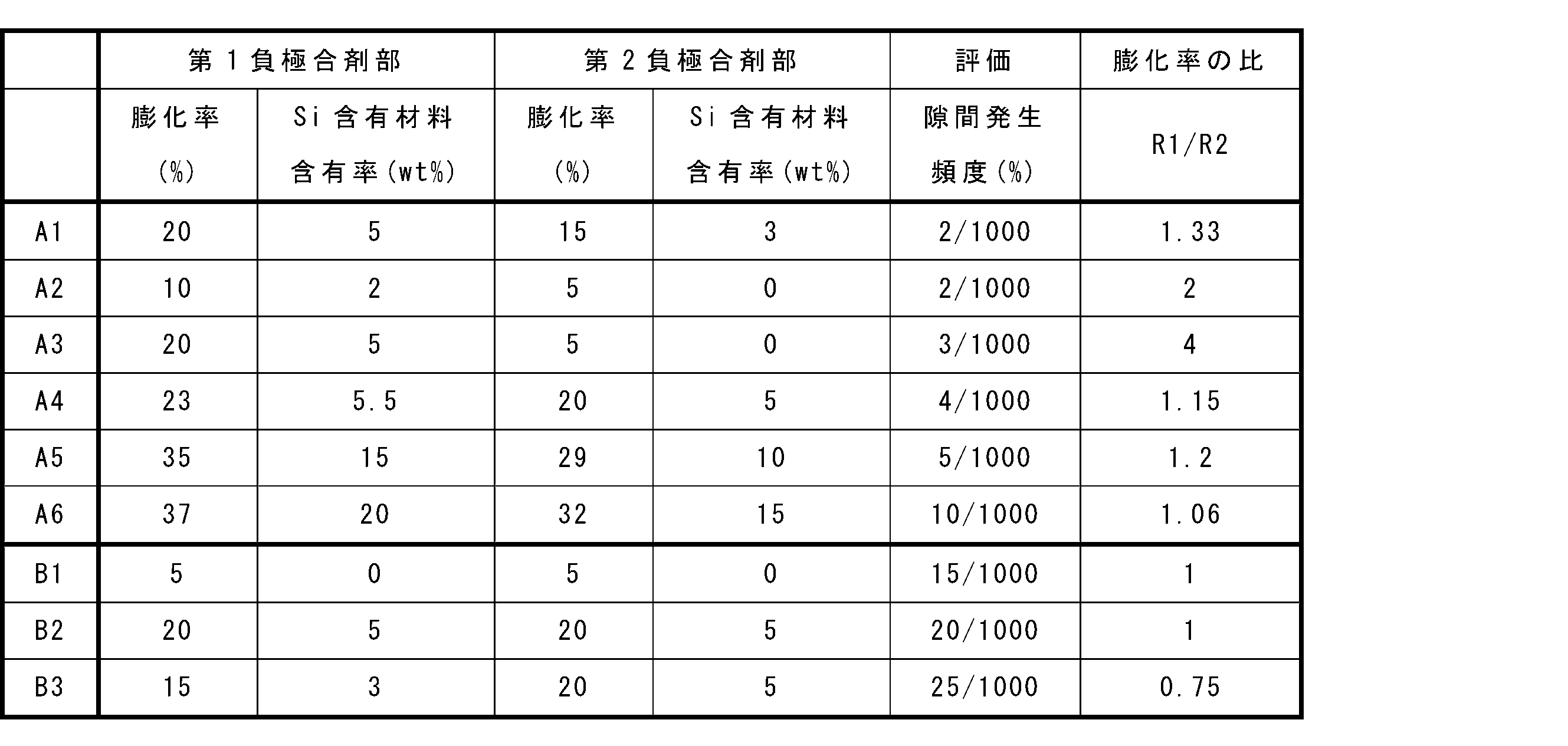
- Examples 1 to 6 and Comparative Examples 1 to 3> [Preparation of negative electrode] A negative electrode having the physical properties shown in Table 1 was produced. Specifically, an appropriate amount of water was added to a predetermined negative electrode mixture to obtain a negative electrode slurry.
- graphite as a negative electrode active material
- SBR styrene-butadiene copolymer rubber
- CMC carboxymethyl cellulose
- the mass ratio of the negative electrode active material (a total of SiO 2 x graphite), SBR, and CMC was 98:1:1.
- the first and second negative electrode slurries were applied to both sides of the copper foil negative electrode current collector, the coating was dried and rolled to form a negative electrode mixture layer, and the negative electrode was obtained as shown in FIG. 3. Specifically, the first negative electrode slurry was applied to one end of the short side of the copper foil along the longitudinal direction of the negative electrode current collector to a predetermined thickness, dried and rolled to form a negative electrode edge portion having a first negative electrode mixture portion. Then, the second negative electrode slurry was applied to the negative electrode current collector other than the negative electrode edge portion to a predetermined thickness, dried and rolled to form a negative electrode main portion having a second negative electrode mixture portion. However, a part of the other end side of the negative electrode current collector was left as an exposed portion. The first negative electrode mixture portion and the second negative electrode mixture portion were rolled simultaneously.
- the positive electrode mixture was a mixture of a lithium-containing composite oxide as a positive electrode active material, carbon black as a conductive agent, and polyvinylidene fluoride (PVDF) as a binder. LiNi 0.8 Co 0.1 Mn 0.1 O 2 was used as the lithium-containing composite oxide. In the positive electrode mixture, the mass ratio of the lithium-containing composite oxide to the carbon black and the PVDF was 98:1:1.
- Positive electrode slurry was applied to both sides of the aluminum foil, which was a positive electrode current collector, and the coating was dried and rolled to form a positive electrode mixture layer, obtaining a positive electrode as shown in FIG. 2.
- the positive electrode slurry was intermittently applied to one end of the short side of the aluminum foil along the longitudinal direction of the positive electrode current collector with a predetermined thickness, dried, and rolled to form a positive electrode edge portion having a first positive electrode mixture portion.
- positive electrode slurry was applied to a predetermined thickness on the positive electrode current collector other than the positive electrode edge portion, dried, and rolled to form a positive electrode main portion having a second positive electrode mixture portion.
- the first positive electrode mixture portion and the second positive electrode mixture portion were rolled simultaneously.
- Eight exposed portions of the positive electrode current collector were provided in the positive electrode edge portion, and a positive electrode lead was attached to each exposed portion.
- the width of the positive electrode edge portion was set to 12 mm, and the width of the positive electrode main portion was set to 62 mm.
- VC Vinylene carbonate
- EC ethylene carbonate
- DMC dimethyl carbonate
- LiPF 6 LiPF 6 was dissolved to prepare an electrolyte.
- the content of VC in the entire electrolyte was 5 mass%.
- the concentration of LiPF 6 in the electrolyte was 1.5 mol/L.
- the positive and negative electrodes were wound with a separator (a microporous polyethylene film) between them to prepare an electrode group.
- the electrodes were stacked so that the edge of the positive electrode was positioned on one end face of the electrode group, and the exposed part of the negative electrode current collector was positioned on the other end face of the electrode group.
- Cylindrical lithium ion secondary batteries as shown in FIG. 1 (batteries A1 to A6 of the embodiment and batteries B1 to B3 of the comparative example) were completed using the electrode group and the electrolyte.
- the multiple positive electrode leads are bundled together and electrically connected to the first portion of the first terminal member.
- the exposed portion of the negative electrode current collector was connected to the end surface current collector plate by laser welding, and the end surface current collector plate was electrically connected to the negative electrode current collector plate via a connecting plate.
- Table 1 shows that by increasing the expansion rate of the negative electrode (here, the negative electrode mixture layer) at the edge of the negative electrode compared to the main part of the negative electrode, it is possible to significantly suppress the occurrence of gaps between the plates near the end faces of the electrode group, even when there is an exposed portion of the positive electrode current collector that does not have a positive electrode mixture layer at the edge of the positive electrode.
- the negative electrode here, the negative electrode mixture layer
- the secondary battery according to the present disclosure is useful as a main power source for mobile communication devices, portable electronic devices, electric vehicles, and the like.
- Electrode group 16 Positive electrode terminal 17: First terminal member (terminal member) 17a: First portion 17b: Second portion 17c: Third portion 18: Second terminal member 19: End face current collector plate 21: Connecting plate 22: Negative electrode current collector plate 22a: Injection hole 23: Sealing plate 24: Insulating member 25: Insulating plate 26: Positive electrode gasket 27: Negative electrode gasket LM: Laser mark
- Positive electrode 110a One end 110b: Other end 112: Positive electrode lead 112a: Folded portion 113: Positive electrode edge portion 113a: Positive electrode central end portion 113b: Positive electrode current collector exposed portion 113c: First positive electrode mixture portion 114: Positive electrode main portion 114c: Second positive electrode mixture portion
- Negative electrode 120a One end 120b: Other end 123: Negative electrode edge portion 123a: Negative electrode central end portion 123b: Negative electrode current collector exposed portion 123c: First negative electrode mixture portion 124: Negative electrode main portion 124c: Second negative electrode mixture portion
Landscapes
- Chemical & Material Sciences (AREA)
- Chemical Kinetics & Catalysis (AREA)
- Electrochemistry (AREA)
- General Chemical & Material Sciences (AREA)
- Composite Materials (AREA)
- Engineering & Computer Science (AREA)
- Manufacturing & Machinery (AREA)
- Battery Electrode And Active Subsutance (AREA)
- Secondary Cells (AREA)
Abstract
Description
本発明の新規な特徴を添付の請求の範囲に記述するが、本発明は、構成および内容の両方に関し、本発明の他の目的および特徴と併せ、図面を照合した以下の詳細な説明によりさらによく理解されるであろう。
正極は、帯状の正極集電体と、正極集電体上に配置された正極合剤層を備える。正極合剤層は膜状であってもよい。正極は、正極集電体と、正極集電体の表面の一部領域に形成された(もしくは担持された)正極合剤層を有する。具体的には、正極は、正極の短手方向の一端を含む正極縁部と、正極縁部以外の正極要部を有する。正極縁部は、正極集電体の長手方向に沿って間欠的に複数箇所設けられた正極集電体の露出部を有する。正極集電体の露出部は、短手方向の一端から正極要部に至るまで正極合剤層を有さない。
負極は、帯状の負極集電体を備える。負極は、負極集電体と、負極集電体の表面の全体もしくは一部領域に形成された(もしくは担持された)負極合剤層もしくは負極活物質層を有してもよい。負極合剤層もしくは負極活物質層は膜状であってもよい。負極合剤層もしくは負極活物質層は、負極集電体の一方または両方の表面に担持されている。
電解質は、液状電解質(電解液)でもよく、ゲル状電解質でもよく、固体電解質でもよい。液状電解質は、例えば、非水溶媒と、非水溶媒に溶解した塩を含む電解液である。電解液における塩の濃度は、例えば、0.5mol/L以上2mol/L以下である。電解液は、公知の添加剤を含有してもよい。
正極と負極との間には、セパレータを介在させることが望ましい。セパレータは、イオン透過度が高く、適度な機械的強度および絶縁性を備えている。セパレータとしては、微多孔薄膜、織布、不織布等を用いることができる。セパレータの材質としては、ポリプロピレン、ポリエチレン等のポリオレフィンが好ましい。
上記記載によって以下の技術が開示される。
(技術1)
正極と、負極と、電解質と、セパレータと、を具備し、
前記正極と、前記負極とが、前記セパレータを介して巻回されており、
前記正極は、帯状の正極集電体と、前記正極集電体上に配置された正極合剤層と、を備え、
前記正極は、前記正極の短手方向の一端を含む正極縁部と、前記正極縁部以外の正極要部と、を有し、
前記正極縁部は、前記正極集電体の長手方向に沿って間欠的に複数箇所設けられた前記正極集電体の露出部を有し、前記露出部は、前記短手方向の前記一端から前記正極要部に至るまで前記正極合剤層を有さず、
前記負極は、帯状の負極集電体を備え、
前記負極は、前記正極縁部の少なくとも一部に対向する負極縁部と、前記負極縁部以外の負極要部と、を有し、
前記負極要部よりも前記負極縁部の前記負極の膨化率が大きい、二次電池。
(技術2)
前記負極は、帯状の負極集電体と、前記負極集電体上に配置された負極合剤層と、を備え、
前記負極合剤層は、シリコンを含むシリコン含有材料を含み、
前記負極要部よりも前記負極縁部の前記負極合剤層の前記シリコン含有材料の含有率が大きい、技術1に記載の二次電池。
(技術3)
前記負極縁部の前記負極合剤層の前記シリコン含有材料の含有率A質量%と、
前記負極要部の前記負極合剤層の前記シリコン含有材料の含有率B質量%が、A≧1.1Bを満たす、技術1または2に記載の二次電池。
(技術4)
前記含有率Aが、1~15重量%であり、
前記含有率Bが、0~12重量%である、技術1~3のいずれか1つに記載の二次電池。
(技術5)
前記負極縁部の膨化率が、1~35%であり、
前記負極要部の膨化率が、0~30%である、技術1~4のいずれか1つに記載の二次電池。
[負極の作製]
表1に示す物性を有する負極を作製した。具体的には、所定の負極合剤に水を適量加え、負極スラリを得た。負極合剤には、負極活物質であるSiOx(x=1.0)と、負極活物質である黒鉛と、結着剤であるスチレン-ブタジエン共重合体ゴム(SBR)と、増粘剤であるカルボキシメチルセルロース(CMC)を混合して、第1負極スラリおよび第2負極スラリを調製した。
正極合剤にNMPを適量加え、正極スラリを得た。正極合剤には、正極活物質であるリチウム含有複合酸化物と、導電剤であるカーボンブラックと、結着剤であるポリフッ化ビニリデン(PVDF)との混合物を用いた。リチウム含有複合酸化物には、LiNi0.8Co0.1Mn0.1O2を用いた。正極合剤において、リチウム含有複合酸化物とカーボンブラックとPVDFとの質量比は、98:1:1とした。
エチレンカーボネート(EC)と、ジメチルカーボネート(DMC)とを1:3の体積比で混合した非水溶媒にビニレンカーボネート(VC)を添加し、LiPF6を溶解させて、電解質を調製した。電解質全体に対するVCの含有率は5質量%とした。電解質中のLiPF6の濃度は1.5mol/Lとした。
不活性ガス雰囲気中で、正極と負極をセパレータ(ポリエチレン製の微多孔膜)介して巻回し、電極群を作製した。正極縁部が電極群の一方の端面側に配置され、負極集電体の露出部を電極群の他方の端面側に配置されるように電極を重ねた。電極群と電解質を用いて、図1に示すようなリ円筒形のチウムイオン二次電池(実施例の電池A1~A6および比較例の電池B1~B3)を完成させた。
各実施例および各比較例の二次電池を1000個ずつ作製し、25℃の温度環境下、0.2Cの定電流充電を行い、電池電圧が4.2Vに到達した段階で、充電電流が0.02Cになるまで定電圧充電を行った。10分間の休止後、0.2Cの定電流放電を、電池電圧が2.5Vになるまで行った。この充放電を100サイクル行った。
本発明を現時点での好ましい実施態様に関して説明したが、そのような開示を限定的に解釈してはならない。種々の変形および改変は、上記開示を読むことによって本発明に属する技術分野における当業者には間違いなく明らかになるであろう。したがって、添付の請求の範囲は、本発明の真の精神および範囲から逸脱することなく、すべての変形および改変を包含する、と解釈されるべきものである。
11:ケース
12:貫通孔
13:凹部
14:電極群
16:正極端子
17:第1端子部材(端子部材)
17a:第1部分
17b:第2部分
17c:第3部分
18:第2端子部材
19:端面集電板
21:連絡板
22:負極集電板
22a:注入孔
23:封口板
24:絶縁部材
25:絶縁板
26:正極ガスケット
27:負極ガスケット
LM:レーザ痕
110a 一端
110b 他端
112 正極リード
112a:折り重ね部
113 正極縁部
113a 正極中央側端部
113b 正極集電体露出部
113c 第1正極合剤部
114 正極要部
114c 第2正極合剤部
120a 一端
120b 他端
123 負極縁部
123a 負極中央側端部
123b 負極集電体露出部
123c 第1負極合剤部
124 負極要部
124c 第2負極合剤部
Claims (5)
- 正極と、負極と、電解質と、セパレータと、を具備し、
前記正極と、前記負極とが、前記セパレータを介して巻回されており、
前記正極は、帯状の正極集電体と、前記正極集電体上に配置された正極合剤層と、を備え、
前記正極は、前記正極の短手方向の一端を含む正極縁部と、前記正極縁部以外の正極要部と、を有し、
前記正極縁部は、前記正極集電体の長手方向に沿って間欠的に複数箇所設けられた前記正極集電体の露出部を有し、前記露出部は、前記短手方向の前記一端から前記正極要部に至るまで前記正極合剤層を有さず、
前記負極は、帯状の負極集電体を備え、
前記負極は、前記正極縁部の少なくとも一部に対向する負極縁部と、前記負極縁部以外の負極要部と、を有し、
前記負極要部よりも前記負極縁部の前記負極の膨化率が大きい、二次電池。 - 前記負極は、帯状の負極集電体と、前記負極集電体上に配置された負極合剤層と、を備え、
前記負極合剤層は、シリコンを含むシリコン含有材料を含み、
前記負極要部よりも前記負極縁部の前記負極合剤層の前記シリコン含有材料の含有率が大きい、請求項1に記載の二次電池。 - 前記負極縁部の前記負極合剤層の前記シリコン含有材料の含有率A質量%と、
前記負極要部の前記負極合剤層の前記シリコン含有材料の含有率B質量%が、A≧1.1Bを満たす、請求項2に記載の二次電池。 - 前記含有率Aが、1~15重量%であり、
前記含有率Bが、0~12重量%である、請求項3に記載の二次電池。 - 前記負極縁部の膨化率が、1~35%であり、
前記負極要部の膨化率が、0~30%である、請求項1~3のいずれか1項に記載の二次電池。
Priority Applications (3)
| Application Number | Priority Date | Filing Date | Title |
|---|---|---|---|
| CN202480009778.0A CN120530510A (zh) | 2023-01-31 | 2024-01-11 | 二次电池 |
| JP2024574370A JPWO2024161939A1 (ja) | 2023-01-31 | 2024-01-11 | |
| EP24749894.2A EP4661145A4 (en) | 2023-01-31 | 2024-01-11 | SECONDARY BATTERY |
Applications Claiming Priority (2)
| Application Number | Priority Date | Filing Date | Title |
|---|---|---|---|
| JP2023013064 | 2023-01-31 | ||
| JP2023-013064 | 2023-01-31 |
Publications (1)
| Publication Number | Publication Date |
|---|---|
| WO2024161939A1 true WO2024161939A1 (ja) | 2024-08-08 |
Family
ID=92146535
Family Applications (1)
| Application Number | Title | Priority Date | Filing Date |
|---|---|---|---|
| PCT/JP2024/000509 Ceased WO2024161939A1 (ja) | 2023-01-31 | 2024-01-11 | 二次電池 |
Country Status (5)
| Country | Link |
|---|---|
| EP (1) | EP4661145A4 (ja) |
| JP (1) | JPWO2024161939A1 (ja) |
| CN (1) | CN120530510A (ja) |
| TW (1) | TW202441834A (ja) |
| WO (1) | WO2024161939A1 (ja) |
Cited By (1)
| Publication number | Priority date | Publication date | Assignee | Title |
|---|---|---|---|---|
| WO2026070042A1 (ja) * | 2024-09-30 | 2026-04-02 | パナソニックIpマネジメント株式会社 | 円筒形二次電池 |
Citations (4)
| Publication number | Priority date | Publication date | Assignee | Title |
|---|---|---|---|---|
| JP2015191879A (ja) * | 2014-03-31 | 2015-11-02 | 株式会社日立製作所 | 捲回型二次電池 |
| JP2016103446A (ja) * | 2014-11-28 | 2016-06-02 | 日立オートモティブシステムズ株式会社 | リチウム二次電池 |
| JP2018106903A (ja) * | 2016-12-26 | 2018-07-05 | トヨタ自動車株式会社 | リチウムイオン二次電池 |
| WO2022209172A1 (ja) * | 2021-03-31 | 2022-10-06 | パナソニックIpマネジメント株式会社 | 二次電池用電極、二次電池、及び二次電池用電極の製造方法 |
Family Cites Families (1)
| Publication number | Priority date | Publication date | Assignee | Title |
|---|---|---|---|---|
| WO2020045375A1 (ja) | 2018-08-31 | 2020-03-05 | パナソニックIpマネジメント株式会社 | 電気化学デバイス |
-
2024
- 2024-01-11 JP JP2024574370A patent/JPWO2024161939A1/ja active Pending
- 2024-01-11 CN CN202480009778.0A patent/CN120530510A/zh active Pending
- 2024-01-11 EP EP24749894.2A patent/EP4661145A4/en active Pending
- 2024-01-11 WO PCT/JP2024/000509 patent/WO2024161939A1/ja not_active Ceased
- 2024-01-17 TW TW113101863A patent/TW202441834A/zh unknown
Patent Citations (4)
| Publication number | Priority date | Publication date | Assignee | Title |
|---|---|---|---|---|
| JP2015191879A (ja) * | 2014-03-31 | 2015-11-02 | 株式会社日立製作所 | 捲回型二次電池 |
| JP2016103446A (ja) * | 2014-11-28 | 2016-06-02 | 日立オートモティブシステムズ株式会社 | リチウム二次電池 |
| JP2018106903A (ja) * | 2016-12-26 | 2018-07-05 | トヨタ自動車株式会社 | リチウムイオン二次電池 |
| WO2022209172A1 (ja) * | 2021-03-31 | 2022-10-06 | パナソニックIpマネジメント株式会社 | 二次電池用電極、二次電池、及び二次電池用電極の製造方法 |
Non-Patent Citations (1)
| Title |
|---|
| See also references of EP4661145A1 * |
Cited By (1)
| Publication number | Priority date | Publication date | Assignee | Title |
|---|---|---|---|---|
| WO2026070042A1 (ja) * | 2024-09-30 | 2026-04-02 | パナソニックIpマネジメント株式会社 | 円筒形二次電池 |
Also Published As
| Publication number | Publication date |
|---|---|
| JPWO2024161939A1 (ja) | 2024-08-08 |
| EP4661145A4 (en) | 2026-04-29 |
| EP4661145A1 (en) | 2025-12-10 |
| TW202441834A (zh) | 2024-10-16 |
| CN120530510A (zh) | 2025-08-22 |
Similar Documents
| Publication | Publication Date | Title |
|---|---|---|
| CN110323485A (zh) | 二次电池 | |
| JP7427629B2 (ja) | 正極及び該正極を含むリチウム電池 | |
| JP7432882B2 (ja) | 非水電解質二次電池 | |
| US20230387384A1 (en) | Method for Manufacturing Positive Electrode for Lithium Secondary Battery and Positive Electrode for Lithium Secondary Battery Manufactured Thereby | |
| JP7507257B2 (ja) | 正極活物質およびこれを含むリチウム二次電池 | |
| CN110785876A (zh) | 锂二次电池用正极、其制备方法以及包含其的锂二次电池 | |
| CN106537665A (zh) | 用于锂电池的阴极 | |
| CN118020190A (zh) | 具有使含氧化硅活性材料的电池达成高功率放电及长循环寿命的高倍率电解质的锂离子电池 | |
| JP2001126733A (ja) | 非水電解質電池 | |
| JP7515076B2 (ja) | 非水電解質二次電池 | |
| WO2020003595A1 (ja) | 非水電解質二次電池 | |
| CN120883406A (zh) | 锂二次电池 | |
| WO2024161939A1 (ja) | 二次電池 | |
| JP7637900B2 (ja) | 非水電解液二次電池用負極および非水電解液二次電池 | |
| WO2013047024A1 (ja) | リチウム二次電池及びこれを用いた車両 | |
| WO2024214763A1 (ja) | 二次電池 | |
| US20200176771A1 (en) | Non-aqueous electrolyte secondary battery | |
| ES2974780T3 (es) | Aditivo irreversible, electrodo positivo que incluye el aditivo irreversible, y batería secundaria de litio que incluye el electrodo positivo | |
| JP2025503126A (ja) | 正極活物質およびこれを含む正極 | |
| JP2005243448A (ja) | 非水電解質二次電池 | |
| WO2021251234A1 (ja) | 電極及びリチウムイオン二次電池 | |
| JP7492775B2 (ja) | 非水二次電池用電解液及び非水二次電池 | |
| WO2024181513A1 (ja) | 二次電池用電極および二次電池 | |
| JP7230569B2 (ja) | リチウムイオン二次電池 | |
| WO2025004811A1 (ja) | 二次電池 |
Legal Events
| Date | Code | Title | Description |
|---|---|---|---|
| 121 | Ep: the epo has been informed by wipo that ep was designated in this application |
Ref document number: 24749894 Country of ref document: EP Kind code of ref document: A1 |
|
| ENP | Entry into the national phase |
Ref document number: 2024574370 Country of ref document: JP Kind code of ref document: A |
|
| WWE | Wipo information: entry into national phase |
Ref document number: 2024574370 Country of ref document: JP |
|
| WWE | Wipo information: entry into national phase |
Ref document number: 202480009778.0 Country of ref document: CN |
|
| WWE | Wipo information: entry into national phase |
Ref document number: 202547076701 Country of ref document: IN |
|
| WWP | Wipo information: published in national office |
Ref document number: 202480009778.0 Country of ref document: CN |
|
| NENP | Non-entry into the national phase |
Ref country code: DE |
|
| WWP | Wipo information: published in national office |
Ref document number: 202547076701 Country of ref document: IN |
|
| WWP | Wipo information: published in national office |
Ref document number: 2024749894 Country of ref document: EP |