WO2024162106A1 - 電池 - Google Patents
電池 Download PDFInfo
- Publication number
- WO2024162106A1 WO2024162106A1 PCT/JP2024/001913 JP2024001913W WO2024162106A1 WO 2024162106 A1 WO2024162106 A1 WO 2024162106A1 JP 2024001913 W JP2024001913 W JP 2024001913W WO 2024162106 A1 WO2024162106 A1 WO 2024162106A1
- Authority
- WO
- WIPO (PCT)
- Prior art keywords
- lithium
- positive electrode
- battery
- sample
- electrode active
- Prior art date
- Legal status (The legal status is an assumption and is not a legal conclusion. Google has not performed a legal analysis and makes no representation as to the accuracy of the status listed.)
- Ceased
Links
Images



Classifications
-
- H—ELECTRICITY
- H01—ELECTRIC ELEMENTS
- H01M—PROCESSES OR MEANS, e.g. BATTERIES, FOR THE DIRECT CONVERSION OF CHEMICAL ENERGY INTO ELECTRICAL ENERGY
- H01M10/00—Secondary cells; Manufacture thereof
- H01M10/05—Accumulators with non-aqueous electrolyte
- H01M10/056—Accumulators with non-aqueous electrolyte characterised by the materials used as electrolytes, e.g. mixed inorganic/organic electrolytes
- H01M10/0564—Accumulators with non-aqueous electrolyte characterised by the materials used as electrolytes, e.g. mixed inorganic/organic electrolytes the electrolyte being constituted of organic materials only
- H01M10/0566—Liquid materials
- H01M10/0568—Liquid materials characterised by the solutes
-
- H—ELECTRICITY
- H01—ELECTRIC ELEMENTS
- H01M—PROCESSES OR MEANS, e.g. BATTERIES, FOR THE DIRECT CONVERSION OF CHEMICAL ENERGY INTO ELECTRICAL ENERGY
- H01M10/00—Secondary cells; Manufacture thereof
- H01M10/05—Accumulators with non-aqueous electrolyte
- H01M10/052—Li-accumulators
-
- H—ELECTRICITY
- H01—ELECTRIC ELEMENTS
- H01M—PROCESSES OR MEANS, e.g. BATTERIES, FOR THE DIRECT CONVERSION OF CHEMICAL ENERGY INTO ELECTRICAL ENERGY
- H01M10/00—Secondary cells; Manufacture thereof
- H01M10/05—Accumulators with non-aqueous electrolyte
- H01M10/056—Accumulators with non-aqueous electrolyte characterised by the materials used as electrolytes, e.g. mixed inorganic/organic electrolytes
- H01M10/0564—Accumulators with non-aqueous electrolyte characterised by the materials used as electrolytes, e.g. mixed inorganic/organic electrolytes the electrolyte being constituted of organic materials only
- H01M10/0566—Liquid materials
- H01M10/0567—Liquid materials characterised by the additives
-
- H—ELECTRICITY
- H01—ELECTRIC ELEMENTS
- H01M—PROCESSES OR MEANS, e.g. BATTERIES, FOR THE DIRECT CONVERSION OF CHEMICAL ENERGY INTO ELECTRICAL ENERGY
- H01M4/00—Electrodes
- H01M4/02—Electrodes composed of, or comprising, active material
- H01M4/36—Selection of substances as active materials, active masses, active liquids
- H01M4/48—Selection of substances as active materials, active masses, active liquids of inorganic oxides or hydroxides
- H01M4/485—Selection of substances as active materials, active masses, active liquids of inorganic oxides or hydroxides of mixed oxides or hydroxides for inserting or intercalating light metals, e.g. LiTi2O4 or LiTi2OxFy
-
- H—ELECTRICITY
- H01—ELECTRIC ELEMENTS
- H01M—PROCESSES OR MEANS, e.g. BATTERIES, FOR THE DIRECT CONVERSION OF CHEMICAL ENERGY INTO ELECTRICAL ENERGY
- H01M4/00—Electrodes
- H01M4/02—Electrodes composed of, or comprising, active material
- H01M4/36—Selection of substances as active materials, active masses, active liquids
- H01M4/48—Selection of substances as active materials, active masses, active liquids of inorganic oxides or hydroxides
- H01M4/52—Selection of substances as active materials, active masses, active liquids of inorganic oxides or hydroxides of nickel, cobalt or iron
- H01M4/525—Selection of substances as active materials, active masses, active liquids of inorganic oxides or hydroxides of nickel, cobalt or iron of mixed oxides or hydroxides containing iron, cobalt or nickel for inserting or intercalating light metals, e.g. LiNiO2, LiCoO2 or LiCoOxFy
-
- H—ELECTRICITY
- H01—ELECTRIC ELEMENTS
- H01M—PROCESSES OR MEANS, e.g. BATTERIES, FOR THE DIRECT CONVERSION OF CHEMICAL ENERGY INTO ELECTRICAL ENERGY
- H01M2300/00—Electrolytes
- H01M2300/0017—Non-aqueous electrolytes
- H01M2300/0025—Organic electrolyte
- H01M2300/0028—Organic electrolyte characterised by the solvent
- H01M2300/0037—Mixture of solvents
-
- Y—GENERAL TAGGING OF NEW TECHNOLOGICAL DEVELOPMENTS; GENERAL TAGGING OF CROSS-SECTIONAL TECHNOLOGIES SPANNING OVER SEVERAL SECTIONS OF THE IPC; TECHNICAL SUBJECTS COVERED BY FORMER USPC CROSS-REFERENCE ART COLLECTIONS [XRACs] AND DIGESTS
- Y02—TECHNOLOGIES OR APPLICATIONS FOR MITIGATION OR ADAPTATION AGAINST CLIMATE CHANGE
- Y02E—REDUCTION OF GREENHOUSE GAS [GHG] EMISSIONS, RELATED TO ENERGY GENERATION, TRANSMISSION OR DISTRIBUTION
- Y02E60/00—Enabling technologies; Technologies with a potential or indirect contribution to GHG emissions mitigation
- Y02E60/10—Energy storage using batteries
Definitions
- This disclosure relates to batteries.
- Patent Document 2 discloses that charging overvoltage can be reduced by dissolving a transition metal in the crystal structure of lithium oxide.
- the present disclosure relates to A battery comprising a positive electrode, a negative electrode, a separator, and an electrolyte;
- the positive electrode has an inverse fluorite crystal structure and contains lithium oxide having a transition metal in solid solution as a positive electrode active material,
- the electrolyte solution contains two or more types of fluorine-containing lithium salts. Provide the battery.
- the technology disclosed herein can improve the cycle characteristics of batteries.
- FIG. 1 is a cross-sectional view showing a schematic configuration of a battery according to an embodiment of the present disclosure.
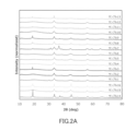
- FIG. 2A shows an X-ray diffraction pattern of a positive electrode active material in which the transition metal M1 is Co.
- FIG. 2B shows an X-ray diffraction pattern of the positive electrode active material when the transition metal M1 is Cu.
- FIG. 2C shows an X-ray diffraction pattern of the positive electrode active material when the transition metal M1 is Fe.
- FIG. 3A shows an SEM image of the positive electrode active material of Sample 3.
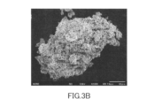
- FIG. 3B shows an SEM image of the positive electrode active material of Sample 17.
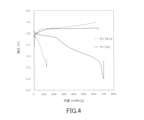
- FIG. 4 is a graph showing charge/discharge curves of Sample 1 and Sample 14.
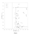
- FIG. 5 is a graph plotting the calculation results of the integrated intensity ratio I 2 /I 1 and the integrated intensity ratio I 3 /I 1 for the positive electrode active materials of Samples 1 to 28.
- the potential range used in batteries using lithium oxide as a positive electrode active material is different from the potential range used in conventional lithium ion batteries.
- the positive electrode active material based on lithium oxide has different characteristics from the positive electrode active material used in conventional lithium ion batteries. Therefore, detailed conditions for improving cycle characteristics, such as the composition of the electrolyte, have hardly been clarified.
- FIG. 1 is a cross-sectional view showing a schematic configuration of a battery 100 according to an embodiment of the present disclosure.
- the battery 100 includes a positive electrode 23, a negative electrode 26, an electrolyte 29, a separator 27, and an exterior 28.
- the positive electrode 23 includes a positive electrode collector 21 and a positive electrode active material layer 22.
- the positive electrode active material layer 22 is disposed on the positive electrode collector 21.
- the negative electrode 26 includes a negative electrode collector 24 and a negative electrode active material layer 25.
- the negative electrode active material layer 25 is disposed on the negative electrode collector 24.
- the separator 27 is disposed between the positive electrode 23 and the negative electrode 26.
- the positive electrode 23 and the negative electrode 26 face each other through the separator 27.
- the positive electrode 23, the negative electrode 26, the separator 27, and the electrolyte 29 are housed in the exterior 28.
- the battery 100 is typically a secondary battery.
- the positive electrode active material layer 22 contains lithium oxide in which the transition metal M1 is dissolved (doped) as the positive electrode active material.
- the lithium oxide in which the transition metal M1 is dissolved has an inverse fluorite crystal structure.
- the inverse fluorite crystal structure is a structure in which the positional relationship between the cations and anions in the fluorite structure is reversed.
- the reason why the electronic conductivity of the lithium oxide in which the transition metal M1 is dissolved is improved is not necessarily clear, but it can be considered as follows. When the transition metal M1 is dissolved in the lithium oxide, the transition metal M1 enters the lithium site, and oxygen atoms are tetrahedral coordinated around the transition metal M1 to form an outer orbital complex.
- Lithium oxide with a transition metal M1 dissolved therein can be a substitutional solid solution.
- the transition metal M1 is not particularly limited as long as it can be dissolved in lithium oxide.
- the transition metal M1 may be, for example, an element selected from the group of elements of groups 3 to 11 in the fourth and fifth periods of the periodic table.
- the transition metal M1 may include at least one element selected from the group consisting of Fe, Co, and Cu.
- the transition metal M1 may be Fe, Co, or Cu.
- the lithium oxide in which the transition metal M1 is dissolved may have a composition represented by the following formulas (1a) and (1b) in a discharged state. According to quantum scientific calculations, when the valence of the transition metal M1 is +3, ⁇ preferably satisfies the relationship 0.0327 ⁇ 0.1484. When the valence of the transition metal M1 is +2, ⁇ preferably satisfies the relationship 0.0490 ⁇ 0.2224.
- the amount of lithium contained in the positive electrode active material is defined as m 0 (mol).
- the amount of transition metal M1 contained in the positive electrode active material is defined as m 1 (mol).
- the ratio (m 1 /(m 0 +m 1 )) is, for example, 0.01 or more and 0.34 or less. By appropriately adjusting the ratio (m 1 /(m 0 +m 1 )), it is possible to suppress an increase in the charging voltage of the battery 100 and improve the discharge capacity of the battery 100.
- the positive electrode current collector 21 is a sheet or film made of a metal material such as aluminum, an aluminum alloy, stainless steel, titanium, or a titanium alloy.
- the sheet or film may be porous or non-porous.
- Metal foil, metal mesh, or the like may be used as the sheet or film.
- a carbon material may be applied to the surface of the positive electrode current collector 21 as a conductive auxiliary material.
- the positive electrode active material layer 22 may contain other materials such as a conductive additive, an ion conductor, and a binder.
- the conductive assistant and ion conductor are used to reduce the resistance of the positive electrode 23.
- the conductive assistant include carbon materials and conductive polymer compounds.
- the carbon materials include carbon black, graphite, acetylene black, carbon nanotubes, carbon nanofibers, graphene, fullerene, and graphite oxide.
- the conductive polymer compounds include polyaniline, polypyrrole, and polythiophene. At least one selected from these conductive assistants can be used.
- ion conductor examples include gel electrolytes such as polymethyl methacrylate and polymethyl methacrylate, organic solid electrolytes such as polyethylene oxide, and inorganic solid electrolytes such as Li 7 La 3 Zr 2 O 12. At least one selected from these ion conductors can be used.
- the binder is used to improve the binding property of the material that constitutes the negative electrode 26.
- binders include polymeric materials such as polyvinylidene fluoride, vinylidene fluoride-hexafluoropropylene copolymer, vinylidene fluoride-tetrafluoroethylene copolymer, polytetrafluoroethylene, carboxymethyl cellulose, polyacrylic acid, styrene-butadiene copolymer rubber, polypropylene, polyethylene, and polyimide. At least one selected from these binders can be used.
- the negative electrode current collector 24 is a sheet or film made of a metal material such as stainless steel, nickel, a nickel alloy, copper, or a copper alloy.
- the sheet or film may be porous or non-porous.
- Metal foil, metal mesh, or the like may be used as the sheet or film.
- a carbon material may be applied to the surface of the negative electrode current collector 24 as a conductive auxiliary material.
- the negative electrode active material layer 25 may contain a negative electrode active material capable of absorbing and releasing lithium.
- negative electrode active materials capable of absorbing and releasing lithium include lithium titanate, graphite, silicon, silicon-containing oxides, zinc alloys, lithium metal, and lithium alloys. At least one selected from these negative electrode active materials can be used. It is more preferable to use lithium metal as the negative electrode active material.
- the theoretical capacity of the positive electrode active material according to the present disclosure is 897 mAh per 1 g of lithium oxide, which is more than three times larger than other positive electrode active materials that have been used conventionally. Therefore, lithium metal is suitable as a negative electrode active material.
- the negative electrode active material layer 25 may contain other materials such as a conductive additive, an ion conductor, and a binder. Materials that can be used as a conductive additive, an ion conductor, and a binder in the positive electrode active material layer 22 can also be used in the negative electrode active material layer 25.
- the electrolyte 29 may be impregnated into the positive electrode 23, the negative electrode 26, and the separator 27.
- the electrolyte 29 may fill the internal space of the exterior 28.
- the electrolyte 29 functions to allow lithium ions to travel between the positive electrode 23 and the negative electrode 26.
- the electrolyte 29 contains two or more types of fluorine-containing lithium salts.
- one of the fluorine-containing lithium salts can be a material that is easily dissolved in a non-aqueous solvent and that easily increases the concentration of lithium ions in the electrolyte 29.
- the other fluorine-containing lithium salt can be a material that is suitable for suppressing decomposition of the electrolyte 29 due to direct contact between the active material and the electrolyte 29. As a result, the cycle characteristics of the battery 100 can be improved. There is also greater freedom in selecting the lithium salt.
- the two or more types of fluorine-containing lithium salts include a first lithium salt and a second lithium salt.
- the first lithium salt includes at least one selected from the group consisting of lithium fluorinated borate and lithium fluorinated phosphate.
- These fluorine-containing lithium salts have the effect of improving the cycle characteristics of the battery 100. Although the reason for this is not entirely clear, it is presumed that the lithium fluorinated borate and lithium fluorinated phosphate form a coating on the surface of the active material, preventing direct contact between the active material and the electrolyte 29 and suppressing decomposition of the electrolyte 29.
- Lithium fluorinated borate may be a compound in which oxygen and fluorine atoms are bonded to boron atoms, and lithium ions are coordinated to compensate for the charge.
- Lithium fluorinated phosphate may be a compound in which oxygen and fluorine atoms are bonded to phosphorus atoms, and lithium ions are coordinated to compensate for the charge.
- the lithium fluoride borate may have a structure in which at least one oxygen atom is bonded to a central boron atom. This configuration is likely to improve the cycle characteristics of the battery 100.
- the lithium fluoride borate may contain lithium difluoro(oxalato)borate (LiFOB). This configuration is likely to improve the cycle characteristics of the battery 100.
- the concentration of the lithium fluoride borate in the electrolyte solution 29 is not particularly limited.
- the concentration of the lithium fluoride borate in the electrolyte solution 29 is, for example, 0.32 mol/L or more and 1.60 mol/L or less. With such a configuration, it is easy to obtain the effect of improving the cycle characteristics of the battery 100.
- the concentration of the lithium fluoride borate in the electrolyte solution 29 may be more than 0.32 mol/L and 1.60 mol/L or less, may be 0.50 mol/L or more and 1.60 mol/L or less, or may be 0.80 mol/L or more and 1.60 mol/L or less.
- the fluorinated lithium phosphate may have a structure in which at least one oxygen atom is bonded to a central phosphorus atom. This configuration makes it easier to obtain the effect of improving the cycle characteristics of the battery 100.
- fluorinated lithium phosphate examples include lithium monofluorophosphate ( Li2PO3F ), lithium difluorophosphate ( LiPO2F2 ), and lithium difluorobisoxalatophosphate.
- Li2PO3F lithium monofluorophosphate
- LiPO2F2 lithium difluorophosphate
- lithium difluorobisoxalatophosphate One or a mixture of two or more selected from these fluorinated lithium phosphates can be used.
- lithium difluorophosphate can be preferably used. With this configuration, it is easy to obtain the effect of improving the cycle characteristics of the battery 100.
- the concentration of the fluorinated lithium phosphate in the electrolyte solution 29 is not particularly limited.
- the concentration of the fluorinated lithium phosphate in the electrolyte solution 29 is, for example, 0.08 mol/L or more and 0.32 mol/L or less. With this configuration, it is easy to obtain the effect of improving the cycle characteristics of the battery 100.
- the second lithium salt is a lithium salt used in combination with the first lithium salt, and is not particularly limited.
- the second lithium salt include lithium hexafluorophosphate (LiPF 6 ), lithium tetrafluoroborate (LiBF 4 ), lithium perchlorate (LiClO 4 ), lithium bis(fluorosulfonyl)imide (LiFSI), lithium bis(trifluoromethanesulfonyl)imide (LiTFSI), lithium bisperfluoroethylsulfonylimide (LiN(SO 2 C 2 F 5 ) 2 ), LiAsF 6 , and LiCF 3 SO 3 . At least one selected from these lithium salts can be used as the second lithium salt.
- lithium hexafluorophosphate can be preferably used. Since lithium hexafluorophosphate is easily dissolved in various nonaqueous solvents, the lithium ion concentration in the electrolyte 29 can be increased by using lithium hexafluorophosphate. This is advantageous for improving the cycle characteristics of the battery 100.
- the concentration of the second lithium salt in the electrolyte solution 29 is not particularly limited.
- the concentration of the second lithium salt in the electrolyte solution 29 is, for example, 0.5 mol/L or more and 3.0 mol/L or less. With this configuration, it is easy to obtain the effect of improving the cycle characteristics of the battery 100.
- the electrolyte 29 contains a lithium salt and a non-aqueous solvent.
- cyclic carbonate ester As the non-aqueous solvent, cyclic carbonate ester, chain carbonate ester, cyclic ether, chain ether, cyclic ester, chain ester, fluorine solvent, nitrile, etc. can be used.
- cyclic carbonate ester include ethylene carbonate, propylene carbonate, butylene carbonate, etc.
- chain carbonate ester include dimethyl carbonate, ethyl methyl carbonate, diethyl carbonate, etc.
- cyclic ether include tetrahydrofuran, 1,4-dioxane, 1,3-dioxolane, etc.
- chain ether examples include 1,2-dimethoxyethane, 1,2-diethoxyethane, etc.
- Examples of cyclic ester include ⁇ -butyrolactone, etc.
- Examples of chain ester include methyl acetate, etc.
- Examples of fluorine solvent include fluoroethylene carbonate, methyl fluoropropionate, fluorobenzene, fluoroethyl methyl carbonate, fluorodimethyl carbonate, etc.
- Examples of nitrile include acetonitrile, etc. At least one selected from these non-aqueous solvents can be used.
- the electrolyte solution 29 may contain a gel electrolyte and/or an ionic liquid.
- the gel electrolyte can be a material obtained by impregnating a polymer material with the electrolyte solution 29.
- the polymer material include polyethylene oxide, polyacrylonitrile, polyvinylidene fluoride, polymethyl methacrylate, and polymers having ethylene oxide bonds.
- Examples of the cations constituting the ionic liquid include aliphatic chain quaternary cations, aliphatic cyclic ammonium, and nitrogen-containing heterocyclic aromatic cations.
- Examples of the aliphatic chain quaternary cations include tetraalkylammonium and tetraalkylphosphonium.
- Examples of the aliphatic cyclic ammonium include pyrrolidiniums, morpholiniums, imidazoliniums, tetrahydropyrimidiniums, piperaziniums, and piperidiniums.
- Examples of the nitrogen-containing heterocyclic aromatic cations include pyridiniums and imidazoliums.
- Examples of anions constituting the ionic liquid include PF6- , BF4- , SbF6- , AsF6- , SO3CF3- , N ( SO2F ) 2- , N ( SO2CF3 ) 2-, N(SO2C2F5)2- , N ( SO2CF3 ) (SO2C4F9)-, C(SO2CF3)3- , etc.
- the ionic liquid may contain a lithium salt.
- the separator 27 is an electrolyte layer having lithium ion conductivity.
- the material of the separator 27 is not particularly limited as long as the passage of lithium ions is permitted.
- the material of the separator 27 may be at least one selected from the group consisting of a solid electrolyte, a gel electrolyte, an ion exchange resin membrane, a semipermeable membrane, and a porous membrane. If the separator 27 is made of these materials, the safety of the battery 100 can be sufficiently ensured.
- the solid electrolyte include a sulfide solid electrolyte such as Li 2 S-P 2 S 5 , and an oxide solid electrolyte such as Li 7 La 3 Zr 2 O 12 (LLZ).
- Examples of the gel electrolyte include a gel electrolyte containing a fluorine resin such as PVdF.
- Examples of the ion exchange resin membrane include a cation exchange membrane and an anion exchange membrane.
- Examples of the porous membrane include a porous membrane made of a polyolefin resin, and a porous membrane made of glass paper obtained by weaving glass fibers into a nonwoven fabric.
- the exterior 28 is made of a material obtained by laminating a metal foil such as aluminum foil with a resin film such as a PET film.
- the exterior 28 may also be a resin or metal container.
- the shape of the battery 100 is not limited to a laminated type. Other shapes of the battery 100 include a coin type, a cylindrical type, a square type, a sheet type, a button type, a flat type, etc.
- the positive electrode active material may contain a transition metal oxide containing a transition metal M2 in addition to lithium oxide having a transition metal M1 dissolved therein.
- a transition metal oxide in the positive electrode active material, the increase in the charging voltage of the battery 100 is suppressed, and the discharge capacity of the battery 100 is improved.
- the transition metal oxide containing the transition metal M2 has a crystal structure different from that of lithium oxide in which the transition metal M1 is dissolved.
- the transition metal oxide containing the transition metal M2 may contain a double oxide containing lithium and the transition metal M2.
- the crystal structure of the double oxide may be different from that of lithium oxide.
- the transition metal oxide containing the transition metal M2 may not contain lithium.
- the transition metal oxide may contain a metal oxide containing only the transition metal M2 as the metal element.
- the transition metal oxide containing the transition metal M2 may contain at least one selected from the group consisting of a double oxide containing lithium and the transition metal M2 and a metal oxide containing only the transition metal M2 as the metal element.
- the transition metal M2 may be, for example, an element selected from the group of elements of Groups 3 to 11 of the fourth and fifth periods of the periodic table.
- the transition metal M2 includes, for example, at least one element selected from the group consisting of Fe, Co, and Cu.
- the transition metal M2 may be Fe, Co, or Cu.
- the transition metal M2 may be the same as or different from the transition metal M1 dissolved in the lithium oxide crystal. Typically, the transition metal M1 and the transition metal M2 are the same element or element group. The transition metal M1 and the transition metal M2 may be the same element. When the transition metal M1 and the transition metal M2 are the same element, it is easy to control the composition of the positive electrode active material. There are also advantages such as ease of production and reduced raw material costs.
- the transition metal oxide may be a residue of the raw material used to dissolve the transition metal M1 in the lithium oxide, or a by-product generated during the synthesis of the positive electrode active material.
- the positive electrode active material contains a transition metal oxide containing a transition metal M2
- the amount of substance of lithium contained in the lithium oxide and the transition metal oxide is defined as m 0 (mol).
- the amount of substance of the transition metal M1 present in the positive electrode active material is defined as m 1 (mol).
- the amount of substance of the transition metal M2 present in the positive electrode active material is defined as m 2 (mol).
- the ratio (m 1 +m 2 )/(m 0 +m 1 +m 2 ) is, for example, 0.01 or more and 0.34 or less.
- the amount of substance m1 is the amount of substance of the transition metal M1 present in the positive electrode active material.
- the above ratio is expressed as ( m1 /( m0 + m1 )).
- the presence of the transition metal oxide can be confirmed by X-ray diffraction measurement.
- the degree of dissolution of the transition metal M1 in the lithium oxide and the suitable amount of the transition metal oxide can be determined based on multiple diffraction peaks attributable to the lithium oxide in which the transition metal M1 is dissolved, and at least one diffraction peak attributable to the transition metal oxide.
- a diffraction peak existing in the range of a diffraction angle 2 ⁇ of 30° to 40° is defined as a first diffraction peak.
- a diffraction peak existing in the range of a diffraction angle 2 ⁇ of 52° to 62° is defined as a second diffraction peak.
- a diffraction peak existing in the range of a diffraction angle 2 ⁇ of 40° to 50° is defined as a third diffraction peak.
- the first diffraction peak is a diffraction peak attributable to the (111) plane of lithium oxide.
- the second diffraction peak is a diffraction peak attributable to the (220) plane of lithium oxide.
- the third diffraction peak is a diffraction peak attributable to a crystal plane of a transition metal oxide.
- the integrated intensity of the first diffraction peak is defined as I 1
- the integrated intensity of the second diffraction peak is defined as I 2
- the integrated intensity of the third diffraction peak is defined as I 3 .
- the integral intensity ratio I2 / I1 is 0.48 or more
- the integral intensity ratio I3 / I1 is 0.10 or more and 1.30 or less.
- the integral intensity ratio I2 / I1 is an index reflecting the degree of solid solubility of the transition metal M1 in the lithium oxide crystal. Assuming that the valence of the transition metal M1 is +3, the valence of lithium is +1, so that two lithium atoms are released from the crystal in addition to the lithium atom substituted with the transition metal M1 to maintain charge neutrality in the crystal. Since the transition metal M1 with a valence greater than that of the lithium atom is taken into the crystal, and two lithium atoms are released from the crystal to maintain charge neutrality, a minute distortion occurs in the crystal structure of the lithium oxide, which is the base material. The larger the distortion, the greater the integral intensity ratio I2 / I1 .
- the ratio of integrated intensities I 3 /I 1 is an index reflecting the amount of residues and/or by-products of the raw material used to dissolve the transition metal M1 in lithium oxide.
- LiCoO 2 is contained in the positive electrode active material as a residue and/or by-product.
- reflection from the (104) plane of LiCoO 2 is observed as the third diffraction peak.
- the ratio of integrated intensities I 3 /I 1 also decreases.
- the diffraction intensity of the third diffraction peak increases, so the ratio of integrated intensities I 3 /I 1 also increases.
- the composition and structure of the residues and/or by-products contained in the positive electrode active material can be determined from the entire X-ray diffraction pattern including the third diffraction peak. When transition metal oxide crystals are present, a diffraction peak appears in the diffraction angle 2 ⁇ range of 40° to 50° regardless of the type of transition metal.
- the transition metal M1 When the transition metal M1 is appropriately dissolved in lithium oxide and the residues and/or by-products are appropriately present without disappearing, the reason why the effect of suppressing the rise in charging voltage and the effect of improving discharge capacity are enhanced is not necessarily clear, but the inventors speculate as follows.
- the positive electrode active material is composed only of lithium oxide in which the transition metal M1 is completely dissolved, the volume contraction of the positive electrode active material during the charging process becomes large, voids are generated between the positive electrode active material and the conductive assistant, the electronic resistance of the entire electrode increases, and an increase in the charging voltage is caused.
- the volume contraction of the positive electrode active material during the charging process is suppressed by utilizing charge compensation due to the valence change of the transition metal M2 due to the moderate presence of residues and/or by-products containing the transition metal M2 in the positive electrode active material.
- the effect of suppressing the rise in charging voltage and the effect of improving discharge capacity are exerted. The fact that these effects can be achieved is supported by the examples described below.
- the lower limit of the integrated intensity ratio I2 / I1 may be 0.50 or 0.55.
- the upper limit of the integrated intensity ratio I2 / I1 is not particularly limited and may be 1.00 or 0.90.
- the integrated intensity ratio I2 / I1 may be 0.50 or more and 1.00 or less, 0.50 or more and 0.90 or less, 0.55 or more and 1.00 or less, or 0.55 or more and 0.90 or less.
- the ratio of integrated intensities I3 / I1 is desirably 0.20 or more.
- the ratio of integrated intensities I3 / I1 may be 1.10 or less, or may be 1.00 or less.
- the ranges of the integrated intensity ratio I2 / I1 and the integrated intensity ratio I3 / I1 may be defined by any combination of the values described above.
- the integrated intensity ratio I2 / I1 may be 0.48 or more
- the integrated intensity ratio I3 / I1 may be 0.20 or more and 1.10 or less.
- the integrated intensity ratio I2 / I1 may be 0.50 or more and 1.00 or less, and the integrated intensity ratio I3 / I1 may be 0.10 or more and 1.30 or less.
- the integrated intensity ratio I2 / I1 may be 0.50 or more and 1.00 or less, and the integrated intensity ratio I3 / I1 may be 0.20 or more and 1.10 or less.
- the integrated intensity ratio I2 / I1 may be 0.50 or more and 1.00 or less, and the integrated intensity ratio I3 / I1 may be 0.20 or more and 1.00 or less.
- the integrated intensity ratio I2 / I1 may be 0.50 or more and 0.90 or less, and the integrated intensity ratio I3 / I1 may be 0.10 or more and 1.30 or less.
- the integrated intensity ratio I2 / I1 may be 0.50 or more and 0.90 or less, and the integrated intensity ratio I3 / I1 may be 0.20 or more and 1.10 or less.
- the integrated intensity ratio I2 / I1 may be 0.50 or more and 0.90 or less, and the integrated intensity ratio I3 / I1 may be 0.20 or more and 1.00 or less.
- the integrated intensity ratio I2 / I1 may be 0.55 or more and 1.00 or less, and the integrated intensity ratio I3 / I1 may be 0.10 or more and 1.30 or less.
- the integrated intensity ratio I2 / I1 may be 0.55 or more and 1.00 or less, and the integrated intensity ratio I3 / I1 may be 0.20 or more and 1.10 or less.
- the integrated intensity ratio I2 / I1 may be 0.55 or more and 1.00 or less, and the integrated intensity ratio I3 / I1 may be 0.20 or more and 1.00 or less.
- the integrated intensity ratio I2 / I1 may be 0.55 or more and 0.90 or less, and the integrated intensity ratio I3 / I1 may be 0.10 or more and 1.30 or less.
- the integrated intensity ratio I2 / I1 may be 0.55 or more and 0.90 or less, and the integrated intensity ratio I3 / I1 may be 0.20 or more and 1.10 or less.
- the integrated intensity ratio I2 / I1 may be 0.55 or more and 0.90 or less, and the integrated intensity ratio I3 / I1 may be 0.20 or more and 1.00 or less.
- the integrated intensity ratio I2 / I1 of a Li2O crystal not doped with a transition metal M1 is about 0.33.
- the integrated intensity ratio I2 / I1 exceeds 0.33 while maintaining the inverse fluorite crystal structure of Li2O , it can be determined that the transition metal M1 is dissolved in the lithium oxide.
- the positive electrode active material has a structure of secondary particles composed of, for example, multiple primary particles of lithium oxide and multiple primary particles of transition metal oxide.
- a positive electrode active material having such a structure can be efficiently manufactured by a synthesis method such as mechanochemical milling.
- the primary particles have a diameter, for example, on the order of nanometers.
- the secondary particles have a diameter, for example, on the order of micrometers.
- the true density of the positive electrode active material is, for example, 2.0 g/cm 3 or more and 3.3 g/cm 3 or less. By appropriately adjusting the true density, it is possible to improve the energy density of the battery 100 compared to conventional lithium secondary batteries.
- the true density can be measured by a pycnometer method after finely pulverizing the positive electrode active material.
- the specific surface area of the positive electrode active material is, for example, 1.6 m 2 /g or more and 60 m 2 /g or less. By appropriately adjusting the specific surface area, it is possible to improve the energy density of the battery 100.
- the specific surface area is a value determined by the BET method.
- the positive electrode active material may have a particulate shape.
- Each particle of the positive electrode active material may have a cross-sectional area of 0.01 ⁇ m 2 or more and 500 ⁇ m 2 or less.
- the cross-sectional area of each particle of the positive electrode active material can be calculated using a cross-sectional SEM image of the positive electrode 23. All particles of the positive electrode active material may have a cross-sectional area in the above range, or a part of the particles (for example, 90% or more by number) may have a cross-sectional area in the above range.
- the positive electrode active material can be manufactured, for example, by a mechanochemical method.
- a mixture is prepared by mixing a lithium oxide powder with a raw material of the transition metal M1.
- the ratio between the lithium oxide and the raw material of the transition metal M1 can be determined so that the ratio ( m1 /( m0 + m1 )) described above falls within a desired range.
- the raw material of the transition metal M1 include an oxide of the transition metal M1, a composite oxide containing lithium and the transition metal M1, and a simple substance of the transition metal M1.
- the synthesis of the positive electrode active material by the mechanochemical method is carried out using a device capable of exerting a mechanochemical effect, such as a ball mill or a bead mill.
- the atmosphere during synthesis is not particularly limited, and may be an air atmosphere, an inert atmosphere, a dry atmosphere, or a dry inert atmosphere.
- an inert gas such as nitrogen, argon, or helium is used.
- the degree of solid solution of the transition metal M1 in lithium oxide can be adjusted. That is, the integral intensity ratio I 2 /I 1 and the integral intensity ratio I 3 /I 1 can be controlled. For example, as the solid solution of the transition metal M1 in lithium oxide progresses with an increase in the rotation speed and the processing time, the ratio I 2 /I 1 increases and the ratio I 3 /I 1 decreases.
- a positive electrode active material that can suppress the increase in charging voltage and improve the discharge capacity can be obtained.
- a battery comprising a positive electrode, a negative electrode, a separator, and an electrolyte;
- the positive electrode has an inverse fluorite crystal structure and contains lithium oxide having a transition metal in solid solution as a positive electrode active material,
- the electrolyte solution contains two or more types of fluorine-containing lithium salts. battery.
- This configuration can improve the cycle characteristics of the battery.
- the positive electrode active material further contains a transition metal oxide containing a transition metal M2, and in an X-ray diffraction pattern of the positive electrode active material measured using Cu-K ⁇ radiation, the ratio of the integrated intensity of the second diffraction peak attributable to the (220) plane of the lithium oxide present in the range of 52° to 62° to the integrated intensity of the first diffraction peak attributable to the (111) plane of the lithium oxide present in the range of diffraction angles 2 ⁇ of 30° to 40° is 0.48 or more, and the ratio of the integrated intensity of the third diffraction peak attributable to the crystal plane of the transition metal oxide present in the range of diffraction angles 2 ⁇ of 40° to 50° to the integrated intensity of the first diffraction peak is 0.10 to 1.30.
- the battery according to any one of the above-mentioned techniques 1 to 11. With such a configuration, it is possible to suppress an increase in charging voltage and improve the discharge capacity.
- the positive electrode active material having such a structure can be efficiently manufactured by various granulation methods.
- each operation in the preparation of the positive electrode active material and each operation in the preparation of the battery were performed in a dry atmosphere or an argon atmosphere.
- a dry atmosphere is an air atmosphere with a dew point of -40°C or less.
- LiFOB Lithium difluoro(oxalato)borate
- Example 4 to 6 The electrolyte solutions of Examples 4 to 6 were prepared by adding lithium difluorophosphate ( LiPO2F2 ) to the electrolyte solution of Comparative Example 1.
- the concentrations of LiPO2F2 in the electrolyte solutions of Examples 4 to 6 were as shown in Table 1. The reason why the concentrations of LiPO2F2 in the electrolyte solutions of Examples 4 to 6 were low is that the solubility of LiPO2F2 in the mixed solvent of ethylene carbonate and diethyl carbonate is low.
- a mixture was obtained by grinding and mixing 1.00 g of Li2O and 0.82 g of LiCoO2 in a mortar. The mixture was placed in a planetary ball mill (Fritsch, P-7 type, 45 mL container) together with 45 g of zirconia balls (diameter 5 mm), and milled at 420 rpm for 100 hours. This produced a positive electrode active material.
- a coin battery conforming to the CR2016 standard was produced using the above positive electrode active material.
- a positive electrode composite material containing a positive electrode active material, acetylene black, and polytetrafluoroethylene in a mass ratio of 7:2:1 was used for the positive electrode.
- Lithium metal was used for the negative electrode.
- a polyolefin porous film was used for the separator. 120 ⁇ L of the electrolyte solution of the examples and comparative examples was used as the electrolyte solution.
- the battery of Comparative Example 1 showed a significant decrease in discharge capacity at the 5th cycle.
- the batteries of Examples 2 to 6 showed high discharge capacity up to the 5th cycle.
- the discharge capacity at the 5th cycle of the battery of Example 1 exceeded the discharge capacity at the 5th cycle of the battery of Comparative Example 1.
- the batteries of Examples 1 to 6 were superior to the battery of Comparative Example 1.
- Example 1 A mixture was obtained by grinding and mixing 1.00 g of Li2O and 0.82 g of LiCoO2 in a mortar. The mixture was placed in a planetary ball mill (Fritsch, P-7 type, 45 mL container) together with 45 g of zirconia balls (diameter 5 mm), and milled at 420 rpm for 100 hours. This resulted in the positive electrode active material of Sample 1.
- Sample 2 A positive electrode active material of Sample 2 was prepared in the same manner as Sample 1, except that the mixture was milled at 600 rpm for 36 hours.
- Sample 3 A positive electrode active material of Sample 3 was prepared in the same manner as Sample 1, except that a planetary ball mill (manufactured by Fritsch, PL-7 type, 45 mL container) was used.
- Sample 4 The positive electrode active material of Sample 4 was prepared on a different date and time by the same method as the positive electrode active material of Sample 3. As described below, the main differences between Sample 3 and Sample 4 are the volume ratio of vinylene carbonate in the battery electrolyte and the amount of the positive electrode mixture.
- Sample 5 A positive electrode active material of Sample 5 was prepared in the same manner as Sample 1, except that 2.00 g of Li 2 O and 1.63 g of LiCoO 2 were used and the mixture was milled at 600 rpm for 100 hours.
- Sample 6 The positive electrode active material of Sample 6 was prepared in the same manner as Sample 1, except that 2.00 g of Li2O and 1.63 g of LiCoO2 were used, and the mixture was milled at 600 rpm for 100 hours, and then the product was heat-treated. The heat treatment was performed in an argon atmosphere at 250°C (ambient temperature) for 6 hours. The temperature was raised for 1 hour, and the product was allowed to cool naturally after the heat treatment.
- Example 7 2.00 g of Li2O and 1.34 g of Co3O4 were ground and mixed in a mortar to obtain a mixture. The mixture was placed in a planetary ball mill (Fritsch, P-7 type, 45 mL container) together with 45 g of zirconia balls (diameter 5 mm), and milled at 420 rpm for 100 hours. This produced the positive electrode active material of Sample 7.
- Sample 8 The positive electrode active material of Sample 8 was prepared in the same manner as Sample 1, except that 2.00 g of Li2O and 1.64 g of LiCoO2 were used.
- Example 9 A mixture was obtained by grinding and mixing 5.00 g of Li2O and 4.08 g of LiCoO2 in a mortar. The mixture was placed in a planetary ball mill (Fritsch, PL-7 type, 80 mL container) together with 98 g of zirconia balls (diameter 5 mm), and milled at 420 rpm for 100 hours. This resulted in the positive electrode active material of Sample 9.
- Sample 10 A positive electrode active material of Sample 10 was prepared in the same manner as Sample 9, except that the treatment time was changed to 150 hours.
- Sample 11 The positive electrode active material of Sample 11 was prepared in the same manner as the positive electrode active material of Sample 3. As described below, the main differences between Sample 3 and Sample 11 are the volume ratio of vinylene carbonate in the electrolyte of the battery and the amount of the positive electrode mixture.
- the positive electrode active material of Sample 12 was made of the same material as the positive electrode active material of Sample 11 and was prepared at the same time. Specifically, the container of Sample 11 was set at one position of a planetary ball mill, and the container of Sample 12 was set at another position of the planetary ball mill. However, as described below, the amount of positive electrode composite material used in the battery of Sample 12 was different from the amount of positive electrode composite material used in the battery of Sample 11.
- the positive electrode active material of Sample 13 was made of the same material as the positive electrode active material of Sample 4 and was prepared at the same time. Specifically, the container of Sample 4 was set at one position of a planetary ball mill, and the container of Sample 13 was set at another position of the planetary ball mill. However, as described later, the type of electrolyte and the amount of positive electrode composite used in the battery of Sample 13 were different from the type of electrolyte and the amount of positive electrode composite used in the battery of Sample 4.
- Sample 14 A positive electrode active material of Sample 14 was prepared in the same manner as Sample 1, except that 2.00 g of Li 2 O and 1.64 g of LiCoO 2 were used and the treatment time was changed to 10 hours.
- Sample 15 The positive electrode active material of Sample 15 was prepared in the same manner as Sample 1, except that 2.00 g of Li2O and 1.63 g of LiCoO2 were used, and the mixture was milled at 600 rpm for 100 hours, and then the product was heat-treated. The heat treatment was performed in an argon atmosphere at 350°C (ambient temperature) for 6 hours. The temperature was raised for 1 hour, and the product was allowed to cool naturally after the heat treatment.
- Sample 16 The positive electrode active material of Sample 16 was prepared in the same manner as Sample 1, except that 2.00 g of Li2O and 1.63 g of LiCoO2 were used, and the mixture was milled at 600 rpm for 100 hours, and then the product was heat-treated. The heat treatment was performed in an argon atmosphere at 450°C (ambient temperature) for 6 hours. The temperature was raised for 1 hour, and the product was allowed to cool naturally after the heat treatment.
- Sample 18 The positive electrode active material of Sample 18 was prepared in the same manner as Sample 17, except that 2.00 g of Li 2 O and 0.67 g of CuO were used.
- Sample 19 A positive electrode active material of Sample 19 was prepared in the same manner as Sample 17, except that 1.99 g of Li 2 O and 1.14 g of CuO were used.
- Sample 20 The positive electrode active material of Sample 20 was prepared in the same manner as Sample 17, except that 2.00 g of Li 2 O and 1.43 g of CuO were used.
- Sample 21 A positive electrode active material of Sample 21 was prepared in the same manner as Sample 17, except that 1.99 g of Li 2 O and 0.66 g of CuO were used and the treatment time was changed to 48 hours.
- Sample 22 The positive electrode active material of Sample 22 was prepared in the same manner as Sample 17, except that 2.00 g of Li 2 O and 0.47 g of CuO were used.
- Sample 24 A positive electrode active material of Sample 24 was prepared in the same manner as Sample 23, except that 2.00 g of Li 2 O and 0.89 g of Fe 2 O 3 were used.
- Example 25 2.00 g of Li2O and 1.29 g of Fe3O4 were ground and mixed in a mortar to obtain a mixture. The mixture was placed in a planetary ball mill (Fritsch, P-7 type, 45 mL container) together with 45 g of zirconia balls (diameter 5 mm), and milled at 420 rpm for 100 hours. This resulted in the positive electrode active material of Sample 25.
- Example 26 A mixture was obtained by grinding and mixing 5.00 g of Li2O and 4.01 g of FeO in a mortar. The mixture was placed in a planetary ball mill (Fritsch, PL-7 type, 80 mL container) together with 98 g of zirconia balls (diameter 5 mm) and milled at 420 rpm for 150 hours. This resulted in the positive electrode active material of Sample 26.
- Sample 27 A positive electrode active material of Sample 27 was prepared in the same manner as Sample 23, except that the mixture was milled at 420 rpm for 72 hours.
- Sample 28 A positive electrode active material of Sample 28 was prepared in the same manner as Sample 23, except that 2.00 g of Li 2 O and 0.63 g of Fe 2 O 3 were used.
- the positive electrode active material was subjected to powder X-ray diffraction measurement.
- a powder X-ray diffractometer (MiniFlex600, manufactured by Rigaku Corporation) was used. The measurement conditions are as follows.
- Cu Ka line detector HyPix400MF Scan step: 0.02 deg.
- Scan speed 2 deg/min 2 ⁇ : 10-80deg The average spectrum of eight measurements was used.
- Figure 2A shows the X-ray diffraction pattern of the positive electrode active material when the transition metal M1 is Co.
- Figure 2B shows the X-ray diffraction pattern of the positive electrode active material when the transition metal M1 is Cu.
- Figure 2C shows the X-ray diffraction pattern of the positive electrode active material when the transition metal M1 is Fe.
- a diffraction peak attributed to reflection from the (013) plane of Li 2 CuO 2 crystal classified into the space group Immm and a diffraction peak attributed to reflection from the (103) plane of Li 2 CuO 2 crystal appear in the range of diffraction angles 2 ⁇ from 40 ° to 50 °.
- the sum of the integrated intensities of each peak was considered to be the integrated intensity I 3 of the third diffraction peak.
- the diffraction peak of Li2CuO2 space group Immm
- this diffraction peak is proportional to the diffraction peak appearing in the range of 40° to 45° and has a weak intensity. Therefore, only the integrated intensity of the diffraction peak appearing in the range of 40° to 45° was used in the calculation as an index showing the abundance ratio of Li2CuO2 to lithium oxide.
- the diffraction peak of LiCoO 2 space group R-3m
- this diffraction peak is in a proportional relationship with the diffraction peaks appearing in the range of 40° to 45° and has a weak intensity. Therefore, only the integrated intensity of the diffraction peaks appearing in the range of 40° to 45° was used in the calculation as an index showing the abundance ratio of LiCoO 2 to lithium oxide.
- FIG. 3A shows an SEM image of the positive electrode active material of Sample 3.
- Fig. 3B shows an SEM image of the positive electrode active material of Sample 17.
- the positive electrode active materials of Sample 3 and Sample 17 had a secondary particle structure.
- the positive electrode active materials of the other samples also had a similar secondary particle structure.
- the positive electrode active material of Samples 1 to 28 was used to prepare coin batteries conforming to the CR2016 standard.
- a positive electrode composite containing a positive electrode active material, acetylene black, and polytetrafluoroethylene in a mass ratio of 7:2:1 was used for the positive electrode.
- a lithium metal foil having a thickness of 0.3 mm was used for the negative electrode.
- a three-layer separator of nonwoven fabric/polyolefin resin film/nonwoven fabric was used for the separator.
- the batteries of Samples 13-1, 13-2, and 13-3 were the same coin batteries using the positive electrode active material of Sample 13, and were subjected to different charge/discharge test conditions.
- the electrolyte A used in the battery of Sample 1 was prepared in the following manner. Ethylene carbonate and diethyl carbonate were mixed in a volume ratio of 1:1. Vinylene carbonate was mixed in a ratio of 1 volume% to the mixture of ethylene carbonate and diethyl carbonate to obtain a mixed solvent. LiPF6 was dissolved in the obtained mixed solvent at a concentration of 1 mol/L to prepare electrolyte A.
- Electrolyte B was prepared in the same manner as electrolyte A, except that the volume ratio of vinylene carbonate in the mixed solvent was changed to 5 volume%.
- Electrolyte C was prepared in the same manner as electrolyte A, except that the volume ratio of vinylene carbonate in the mixed solvent was changed to 10 volume%.
- Electrolyte D was prepared in the same manner as electrolyte A, except that vinylene carbonate was not used. Battery performance varies slightly depending on the amount of vinylene carbonate. However, the effect of vinylene carbonate saturates at about 1 volume%, so the difference in battery performance due to the amount of vinylene carbonate is small.
- Example 1 The upper voltage limit was set to 3.5 V, the upper charge capacity limit was set to 647 mAh/g, and the battery of Sample 1 was charged at a current value of 64.7 mA/g.
- the charge capacity, voltage at 500 mAh/g, and voltage at 600 mAh/g are shown in Table 3.
- Table 3 shows the discharge capacities at each voltage of 2.2 V, 2.0 V, 1.8 V, and 1.5 V.
- the unit of capacity "mAh/g” represents the capacity per 1 g of Li 2 O.
- the unit of current value "mA/g” represents the current value per 1 g of Li 2 O.
- Example 14 The upper voltage limit was set to 3.5 V, the upper charge capacity limit was set to 647 mAh/g, and the battery of sample 14 was charged at a current value of 64.7 mA/g.
- the charge capacity, voltage at 500 mAh/g, and voltage at 600 mAh/g are shown in Table 3. After a 20-minute break, constant-current discharge was performed at a current value of 64.7 mA/g down to 1.5 V.
- Table 3 shows the discharge capacities at voltages of 2.2 V, 2.0 V, 1.8 V, and 1.5 V.
- Figure 4 is a graph showing the charge/discharge curves of Sample 1 and Sample 14.
- the difference between Sample 1 and Sample 14 is the amount of raw materials and the milling time.
- the charging voltage of the battery of Sample 14 reached 3.5 V before the charging capacity reached 647 mAh/g. Therefore, the discharge capacity of the battery of Sample 14 was small.
- the charging voltage of the battery of Sample 1 was flat until it reached the upper limit of the charging capacity of 647 mAh/g.
- the battery of Sample 1 also showed a large discharge capacity. In other words, the increase in the charging voltage was suppressed and the discharge capacity was improved in the battery of Sample 1. It is believed that the positive electrode active material of Sample 14 contained excessive raw material residues.
- the amount of the positive electrode mixture used in the battery of Sample 1 and the battery of Sample 14 is also different, but the effect of the difference in the amount of the positive electrode mixture on the charging voltage and discharge capacity is very small compared to the difference in the physical properties of the positive electrode active material.
- the batteries of Sample 1 and Sample 14 were repeatedly charged and discharged under the conditions described above.
- the ratio of the discharge capacity in the second cycle to the charge capacity in the second cycle was calculated as the Coulombic efficiency (unit: %).
- the Coulombic efficiency of the battery of Sample 1 was 99.7%.
- the Coulombic efficiency of the battery of Sample 14 was 84.1%.
- the battery of Sample 1 also had excellent Coulombic efficiency.
- Example 2 A charge/discharge test was carried out on the battery of Sample 2 under the same conditions as those of Sample 1. The results are shown in Table 4.
- Example 3 The upper voltage limit was set to 3.4 V, the upper charge capacity limit was set to 600 mAh/g, and the battery of sample 3 was charged at a current value of 50.0 mA/g.
- the charge capacity, the voltage at 500 mAh/g, and the voltage at 600 mAh/g are shown in Table 4.
- After a 20-minute pause constant current discharge was performed at a current value of 50.0 mA/g to 1.8 V. Then, discharge was performed at a constant voltage of 1.8 V until the current value reached 5 mA/g.
- the discharge capacity at each voltage of 2.2 V, 2.0 V, and 1.8 V is shown in Table 4.
- Example 4 The upper voltage limit was set to 3.4 V, the upper charge capacity limit was set to 600 mAh/g, and the battery of sample 4 was charged at a current value of 50.0 mA/g.
- the charge capacity, the voltage at 500 mAh/g, and the voltage at 600 mAh/g are shown in Table 4. After a 20-minute pause, constant current discharge was performed at a current value of 50.0 mA/g to 1.5 V. Then, constant voltage discharge at 1.5 V was performed for 66 hours. Table 4 shows the discharge capacities at each voltage of 2.2 V, 2.0 V, 1.8 V, and 1.5 V.
- Sample 2 has a higher rotation speed and a shorter processing time than sample 1. By increasing the rotation speed, the increase in charging voltage was suppressed and the discharge capacity was improved, just like sample 1.
- Samples 3 and 4 are samples in which the type of ball mill used is different from that of sample 1. Even when the type of ball mill was changed, the increase in charging voltage was suppressed and the discharge capacity was improved, just like sample 1.
- the battery sample 2 was repeatedly charged and discharged under the conditions described above.
- the ratio of the discharge capacity in the second cycle to the charge capacity in the second cycle was calculated as the coulombic efficiency (unit: %) for the battery sample 2.
- the coulombic efficiency of the battery sample 2 was 94.8%.
- the upper limit voltage was set to 3.4 V
- the lower limit voltage was set to 1.5 V
- the upper limit of the charge/discharge capacity in the first cycle was set to 300 mAh/g
- the upper limit of the charge/discharge capacity in the second cycle was set to 400 mAh/g
- the upper limit of the charge/discharge capacity in the third cycle was set to 500 mAh/g.
- the batteries of samples 5 to 7, samples 15 and 16 were charged and discharged at a current value of 50.0 mA/g.
- the rest time when shifting from the charge process to the discharge process was 20 minutes. If the voltage reached 1.5 V before reaching a predetermined capacity in the discharge process, constant voltage discharge at 1.5 V was performed for 1 hour.
- the charge capacity in the third cycle and the voltage at 500 mAh/g during the charge in the third cycle are shown in Table 5.
- the discharge capacity at each voltage of 2.5 V, 2.2 V, 2.0 V, 1.8 V, and 1.5 V during the discharge in the third cycle are shown in Table 5.
- Example 8 The upper limit voltage was set to 3.4 V, the lower limit voltage was set to 1.8 V, the upper limit of the charge/discharge capacity in the first cycle was set to 300 mAh/g, the upper limit of the charge/discharge capacity in the second cycle was set to 400 mAh/g, and the upper limit of the charge/discharge capacity in the third cycle was set to 500 mAh/g, and the battery of sample 8 was charged and discharged at a current value of 50.0 mA/g. The rest time when shifting from the charge process to the discharge process was 20 minutes. The voltage did not reach 1.8 V before reaching a predetermined capacity in the discharge process.
- the charge capacity in the third cycle and the voltage at 500 mAh/g during the charge in the third cycle are shown in Table 5.
- the discharge capacity at each voltage of 2.5 V, 2.2 V, 2.0 V, and 1.8 V during the discharge in the third cycle are shown in Table 5.
- Example 9 The upper limit voltage was set to 3.4 V, the lower limit voltage was set to 1.8 V, the upper limit of the charge/discharge capacity in the first cycle was set to 300 mAh/g, the upper limit of the charge/discharge capacity in the second cycle was set to 400 mAh/g, and the upper limit of the charge/discharge capacity in the third cycle was set to 500 mAh/g, and the battery of sample 9 was charged and discharged at a current value of 50.0 mA/g. The rest time when shifting from the charge process to the discharge process was 20 minutes.
- the upper limit voltage was set to 3.4 V
- the lower limit voltage was set to 1.8 V
- the upper limit of the charge/discharge capacity in the first cycle was set to 300 mAh/g
- the upper limit of the charge/discharge capacity in the second cycle was set to 400 mAh/g
- the upper limit of the charge/discharge capacity in the third cycle was set to 500 mAh/g
- the battery of sample 10 was charged and discharged at a current value of 50.0 mA/g.
- the rest time when shifting from the charge process to the discharge process was 20 minutes.
- the voltage did not reach 1.8 V before reaching a predetermined capacity in the discharge process.
- the charge capacity in the third cycle and the voltage at 500 mAh/g during the charge in the third cycle are shown in Table 5.
- the discharge capacity at each voltage of 2.5 V, 2.2 V, 2.0 V, and 1.8 V during the discharge in the third cycle are shown in Table 5.
- the upper limit voltage was set to 3.4 V, the lower limit voltage to 1.8 V, the upper limit of the charge/discharge capacity in the first cycle to 300 mAh/g, the upper limit of the charge/discharge capacity in the second cycle to 500 mAh/g, the upper limit of the charge/discharge capacity in the third cycle to 600 mAh/g, and the upper limit of the charge/discharge capacity in the fourth cycle to 700 mAh/g, and the batteries of samples 11 and 12 were charged and discharged at a current value of 50.0 mA/g.
- the rest time when shifting from the charge process to the discharge process was 20 minutes.
- the voltage did not reach 1.8 V before reaching a predetermined capacity in the discharge process.
- the charge capacity in the second cycle and the voltage at 500 mAh/g during the charge in the second cycle are shown in Table 5.
- the discharge capacity at each voltage of 2.5 V, 2.2 V, 2.0 V, and 1.8 V during the discharge in the second cycle are shown in Table 5.
- the positive electrode active materials of Samples 5, 6, 15, and 16 were manufactured under the same conditions, except for the processing temperature.
- the charge voltage of the battery of Sample 15 was slightly high, and the discharge capacity was small.
- the charge capacity and discharge capacity of the battery of Sample 16 were small.
- the batteries of Samples 5 and 6 showed a low charge voltage and a large discharge capacity.
- the battery of sample 7 includes a positive electrode active material produced using Co3O4 as a raw material for the transition metal M1.
- the battery of sample 8 includes a positive electrode active material produced using LiCoO2 as a raw material for the transition metal M1. Whether an oxide or a composite oxide containing only Co is used as a raw material for the transition metal M1, the effect of suppressing an increase in charging voltage and the effect of improving discharge capacity were obtained.
- Samples 9 to 12 are samples in which the type of ball mill used is different from that used in samples 5 to 8. Even when the type of ball mill was changed, the increase in charging voltage was suppressed and the discharge capacity was improved, just as in samples 5 to 8.
- the ratio of the discharge capacity at the fourth cycle to the charge capacity at the fourth cycle was calculated as the Coulombic efficiency (unit: %).
- the Coulombic efficiency of the batteries of Sample 11 and Sample 12 was both 100.0%.
- Example 13-1 The upper voltage limit was set to 3.4 V, the upper charge capacity limit was set to 600 mAh/g, and the battery of sample 13-1 was charged at a current value of 50.0 mA/g.
- the charge capacity, the voltage at 500 mAh/g, and the voltage at 600 mAh/g are shown in Table 6A.
- constant current discharge was performed at a current value of 50.0 mA/g to 1.5 V.
- constant voltage discharge was performed at 1.5 V until the current reached 5 mA/g or until 24 hours had elapsed.
- the discharge capacities at each voltage of 2.2 V, 2.0 V, 1.8 V, and 1.5 V are shown in Table 6A.
- Example 13-2 The upper voltage limit was set to 3.4 V, the upper charge capacity limit was set to 647 mAh/g, and the battery of sample 13-1 was charged at a current value of 64.7 mA/g.
- the charge capacity, the voltage at 500 mAh/g, and the voltage at 600 mAh/g are shown in Table 6A.
- constant current discharge was performed at a current value of 50.0 mA/g to 1.5 V.
- constant voltage discharge was performed at 1.5 V until the current reached 5 mA/g or until 24 hours had elapsed.
- the discharge capacities at each voltage of 2.2 V, 2.0 V, 1.8 V, and 1.5 V are shown in Table 6A.
- the positive electrode active material used in the battery of Sample 13-1 and the battery of Sample 13-2 is the same. As shown in Table 6A, even when the charge/discharge test conditions were changed from those of Sample 13-1 to those of Sample 13-2, the increase in charging voltage was suppressed and the discharge capacity was improved, just like in Sample 1.
- Example 13-3 The upper limit voltage was 3.4V, the lower limit voltage was 1.8V, the upper limit of the charge/discharge capacity in the first cycle was 300mAh/g, the upper limit of the charge/discharge capacity in the second cycle was 400mAh/g, the upper limit of the charge/discharge capacity in the third cycle was 500mAh/g, the upper limit of the charge/discharge capacity in the fourth cycle was 600mAh/g, and the upper limit of the charge/discharge capacity in the fifth cycle was 700mAh/g, and the battery of sample 13-3 was charged and discharged at a current value of 50.0mA/g. The rest time when shifting from the charging process to the discharging process was 20 minutes.
- the charge capacity in the third cycle, the voltage at 500mAh/g during the third cycle charge, and the discharge capacity at each voltage of 2.5V, 2.2V, 2.0V, and 1.8V during the third cycle discharge are shown in Table 6B.
- the charge capacity at the fifth cycle, the voltage at 700 mAh/g during the fifth cycle of charging, and the discharge capacity at voltages of 2.5 V, 2.2 V, 2.0 V, and 1.8 V during the fifth cycle of discharging are shown in Table 6C.
- the battery of sample 13-3 exhibited a low charging voltage and a large discharge capacity in both the third and fifth cycles.
- Example 21 The upper limit voltage was set to 3.4 V, the upper limit of the charge capacity was set to 533 mAh/g, and the battery of sample 20 was charged at a current value of 53.3 mA/g. After a 20-minute pause, constant-current discharge was performed to 1.0 V at a current value of 53.3 mA/g. This cycle was repeated three times.
- the charge capacity at the third cycle and the voltage at 200 mAh/g during the third cycle charge are shown in Table 7A.
- the discharge capacity at each voltage of 2.2 V, 2.0 V, 1.8 V, and 1.5 V during the third cycle discharge are shown in Table 7A.
- the upper limit voltage was set to 3.4V
- the lower limit voltage was set to 1.5V
- the upper limit of the charge/discharge capacity in the first cycle was set to 300mAh/g
- the upper limit of the charge/discharge capacity in the second cycle was set to 400mAh/g
- the upper limit of the charge/discharge capacity in the third cycle was set to 500mAh/g
- the batteries of samples 17 to 20 and sample 22 were charged and discharged at a current value of 50.0mA/g.
- the rest time when shifting from the charge process to the discharge process was 20 minutes.
- a constant voltage discharge at 1.5V was performed for 1 hour.
- the charge capacity in the third cycle and the voltage at each capacity in the third cycle are shown in Table 7A.
- the discharge capacity at each voltage of 2.5V, 2.2V, 2.0V, 1.8V, and 1.5V during the discharge in the third cycle are shown in Table 7B.
- the batteries of Sample 21 and Sample 22 reached an upper voltage limit of 3.4 V with charge capacities of 240.8 mAh/g and 261.1 mAh/g, respectively.
- the discharge capacities of the batteries of Sample 21 and Sample 22 were also low.
- the batteries of Samples 17 to 20 showed low charge voltages and large discharge capacities.
- the reasons why the charging voltage was high and the discharge capacity was low in the batteries of Sample 21 and Sample 22 include the short treatment time and the small amount of CuO.
- Example 23 to 28 The upper voltage limit was set to 3.4 V, the upper charge capacity limit was set to 300 mAh/g, and the batteries of samples 23 to 28 were charged at a current value of 50.0 mA/g.
- the charge capacity, the voltage at 200 mAh/g, and the voltage at 300 mAh/g are shown in Table 8. After a 20-minute pause, constant current discharge was performed at a current value of 50.0 mA/g to 1.5 V (1.8 V for sample 26). Then, constant voltage discharge was performed at 1.5 V (1.8 V for sample 26) for 1 hour. Table 8 shows the discharge capacity at each voltage of 2.2 V, 2.0 V, 1.8 V, and 1.5 V.
- the charging voltage of the batteries of samples 23 to 26 was lower than that of the batteries of samples 27 and 28.
- the discharge capacity of the batteries of samples 27 and 28 was small.
- the batteries of samples 23 to 26 showed a large discharge capacity.
- the reasons why the charging voltage was high and the discharge capacity was low in the batteries of Sample 27 and Sample 28 include the low rotation speed of the device, the short processing time, and the small amount of Fe.
- the integrated intensity ratio I2 / I1 and I3 / I1 of the positive electrode active materials of Samples 1 to 28 is a graph plotting the calculation results of the integrated intensity ratios I2 / I1 and I3 / I1 of the positive electrode active materials of Samples 1 to 28.
- the horizontal axis represents the integrated intensity ratio I2 / I1 .
- the vertical axis represents the integrated intensity ratio I3 / I1 .
- the numbers "1, 2, 3...28" represent Samples 1 to 28, respectively.
- the integrated intensity ratio I2 / I1 in the Li2O single crystal is about 0.33.
- a small integral intensity ratio I2 / I1 indicates a low degree of solid solubility of the transition metal M1.
- a large integral intensity ratio I2 / I1 indicates a high degree of solid solubility of the transition metal M1.
- the integral intensity ratios I2 / I1 of the batteries of samples 1 to 13, 17 to 20, and 23 to 26 were 0.48 or more. It is considered that in these samples, the solid solution of the transition metal M1 in lithium oxide progressed sufficiently, and the effect of improving electronic conductivity and ionic conductivity was sufficiently obtained.
- a small integral intensity ratio I3 / I1 indicates a small amount of residues and/or by-products.
- a large integral intensity ratio I3 / I1 indicates a large amount of residues and/or by-products.
- the integral intensity ratios I3 / I1 of the batteries of samples 1 to 13, 17 to 20, and 23 to 26 were in the range of 0.10 to 1.30. In other words, the positive electrode active materials used in these batteries contained a moderate amount of residues and/or by-products.
- the technology of the present disclosure is useful for batteries such as lithium secondary batteries.
Landscapes
- Chemical & Material Sciences (AREA)
- Chemical Kinetics & Catalysis (AREA)
- Electrochemistry (AREA)
- General Chemical & Material Sciences (AREA)
- Inorganic Chemistry (AREA)
- Engineering & Computer Science (AREA)
- Manufacturing & Machinery (AREA)
- Physics & Mathematics (AREA)
- Condensed Matter Physics & Semiconductors (AREA)
- General Physics & Mathematics (AREA)
- Secondary Cells (AREA)
- Battery Electrode And Active Subsutance (AREA)
Abstract
Description
正極、負極、セパレータ及び電解液を備え、
前記正極は、逆ホタル石型結晶構造を有し、かつ、遷移金属が固溶した酸化リチウムを正極活物質として含み、
前記電解液は、2種類以上のフッ素含有リチウム塩を含む、
電池を提供する。
酸化リチウムと過酸化リチウムとの間のレドックス反応を活用することによって、従来のリチウムイオン電池と比べて高い理論容量を有する電池が得られる。理論容量は、1gの酸化リチウムあたり897mAhである。一方、充電時に生成する過酸化リチウムは過酸化物であるため不安定であり、電解液との反応によって分解する懸念がある。さらに、従来のリチウムイオン電池では2.5Vから4.5V(vs.Li/Li+)程度で充放電が行われるのに対し、酸化リチウムを正極活物質として用いた電池では1.8Vから3.4V(vs.Li/Li+)程度で充放電が行われる。充電電位がそれ以上上がると酸素ガスが発生するためである。つまり、酸化リチウムを正極活物質として用いた電池において使用する電位範囲は、従来のリチウムイオン電池において使用する電位範囲と異なる。このように、酸化リチウムをベースとした正極活物質は、従来のリチウムイオン電池に用いられる正極活物質と異なる特徴を有する。そのため、電解液の組成など、サイクル特性を改善するための詳細な条件については殆ど明らかにされていない。
図1は、本開示の一実施形態に係る電池100の概略構成を示す断面図である。電池100は、正極23、負極26、電解液29、セパレータ27及び外装28を備えている。正極23は、正極集電体21及び正極活物質層22を有する。正極活物質層22は、正極集電体21の上に配置されている。負極26は、負極集電体24及び負極活物質層25を有する。負極活物質層25は、負極集電体24の上に配置されている。正極23と負極26との間にセパレータ27が配置されている。セパレータ27を介して、正極23と負極26とが互いに向かい合っている。正極23、負極26、セパレータ27及び電解液29は、外装28に収められている。電池100は、典型的には二次電池である。
正極23での反応:Li2O2+2Li++2e-⇔2Li2O
負極26での反応:Li⇔Li++e-
遷移金属M1の価数が+2の場合:(Li(1-2α)M1α)2O・・・(1b)
(付記)
以上の実施形態の記載により、下記の技術が開示される。
正極、負極、セパレータ及び電解液を備え、
前記正極は、逆ホタル石型結晶構造を有し、かつ、遷移金属が固溶した酸化リチウムを正極活物質として含み、
前記電解液は、2種類以上のフッ素含有リチウム塩を含む、
電池。
前記2種類以上のフッ素含有リチウム塩が第1リチウム塩及び第2リチウム塩を含み、前記第1リチウム塩は、フッ素化ホウ酸リチウム及びフッ素化リン酸リチウムからなる群より選ばれる少なくとも1つを含む、技術1に記載の電池。これらのフッ素含有リチウム塩には、電池のサイクル特性を改善する効果がある。
前記フッ素化ホウ酸リチウムは、中心原子であるホウ素原子に少なくとも1つの酸素原子が結合した構造を有する、技術2に記載の電池。このような構成によれば、電池のサイクル特性を改善する効果が得られやすい。
前記フッ素化ホウ酸リチウムがジフルオロ(オキサラト)ホウ酸リチウムを含む、技術2又は3に記載の電池。このような構成によれば、電池のサイクル特性を改善する効果が得られやすい。
前記電解液におけるフッ素化ホウ酸リチウムの濃度が0.32mol/リットル以上1.60mol/リットル以下である、技術2から4のいずれか1項に記載の電池。このような構成によれば、電池のサイクル特性を改善する効果が得られやすい。
前記フッ素化リン酸リチウムは、中心原子であるリン原子に少なくとも1つの酸素原子が結合した構造を有する、技術2に記載の電池。このような構成によれば、電池のサイクル特性を改善する効果が得られやすい。
前記フッ素化リン酸リチウムがジフルオロリン酸リチウムを含む、技術2から6のいずれか1項に記載の電池。このような構成によれば、電池のサイクル特性を改善する効果が得られやすい。
前記電解液におけるフッ素化リン酸リチウムの濃度が0.08mol/リットル以上0.32mol/リットル以下である、技術2から7のいずれか1項に記載の電池。このような構成によれば、電池のサイクル特性を改善する効果が得られやすい。
前記第2リチウム塩がヘキサフルオロリン酸リチウムを含む、技術2から8のいずれか1項に記載の電池。ヘキサフルオロリン酸リチウムは各種の非水溶媒に溶解しやすいので、ヘキサフルオロリン酸リチウムを使用することによって電解液におけるリチウムイオン濃度を高めることができる。
前記正極活物質が粒子状の形状を有し、前記正極活物質の粒子が0.01μm2以上500μm2以下の断面積を有する、技術1から9のいずれか1項に記載の電池。正極活物質の粒子の大きさを適切に調節することによって、電池のサイクル特性を改善することができる。
前記負極がリチウム金属を含む、技術1から10のいずれか1項に記載の電池。このような構成によれば、電池のエネルギー密度を高めることができる。
前記正極活物質は、遷移金属M2を含む遷移金属酸化物を更に含み、Cu-Kα線を用いて測定された前記正極活物質のX線回折パターンにおいて、30°から40°の回折角2θの範囲に存在する前記酸化リチウムの(111)面に帰属される第1の回折ピークの積分強度に対する、52°から62°の前記回折角2θの範囲に存在する前記酸化リチウムの(220)面に帰属される第2の回折ピークの積分強度の比が0.48以上であり、前記第1の回折ピークの前記積分強度に対する、40°から50°の前記回折角2θの範囲に存在する前記遷移金属酸化物の結晶面に帰属される第3の回折ピークの積分強度の比が0.10以上1.30以下である、技術1から11のいずれか1項に記載の電池。このような構成によれば、充電電圧の上昇を抑制でき、かつ、放電容量を向上させることができる。
前記正極活物質は、前記酸化リチウムの複数の一次粒子及び前記遷移金属酸化物の複数の一次粒子から構成される二次粒子の構造を有する、技術12に記載の電池。このような構造を有する正極活物質は各種の造粒方法によって効率的に製造されうる。
(比較例1)
エチレンカーボネートとジエチルカーボネートとを1:1の体積比で混合して混合溶媒を得た。混合溶媒にLiPF6を1mol/リットルの濃度で溶解させて比較例1の電解液を得た。
比較例1の電解液にジフルオロ(オキサラト)ホウ酸リチウム(LiFOB)を加えて実施例1から3の電解液を調製した。実施例1から3の電解液におけるLiFOBの濃度は、表1に示す通りであった。
比較例1の電解液にジフルオロリン酸リチウム(LiPO2F2)を加えて実施例4から6の電解液を調製した。実施例4から6の電解液におけるLiPO2F2の濃度は、表1に示す通りであった。実施例4から6の電解液におけるLiPO2F2の濃度が低い理由は、エチレンカーボネートとジエチルカーボネートとの混合溶媒に対するLiPO2F2の溶解度が小さいためである。
1.00gのLi2O及び0.82gのLiCoO2を乳鉢で粉砕及び混合して混合物を得た。混合物を45gのジルコニアボール(直径5mm)とともに遊星型ボールミル(フリッチュ社製、P-7型、45mL容器)に入れ、420rpm、100時間の条件で混合物をミリング処理した。これにより、正極活物質を得た。
上記の正極活物質を用いてCR2016規格のコイン電池を作製した。正極には、正極活物質、アセチレンブラック及びポリテトラフルオロエチレンを7:2:1の質量比で含む正極合材を用いた。負極にはリチウム金属を用いた。セパレータにはポリオレフィン多孔質膜を用いた。電解液として、実施例及び比較例の電解液を120μL用いた。
上限電圧を3.4V、充電容量の上限を600mAh/gに定め、実施例及び比較例の電池を0.40mAの電流値にて充電した。20分間休止した後、電圧が1.8Vに達するまで0.40mAで定電流放電を行った。定電流放電の後、5mA/gの電流値に達するまで1.8Vで定電圧放電を行った。電流値の単位「mA/g」は、1gのLi2Oあたりの電流値を表す。このような充放電サイクルを10回繰り返した。1サイクル目及び5サイクル目の充電容量及び放電容量を表1に示す。表1において、容量の単位「mAh/g」は、1gのLi2Oあたりの容量を表す。

(サンプル1)
1.00gのLi2O及び0.82gのLiCoO2を乳鉢で粉砕及び混合して混合物を得た。混合物を45gのジルコニアボール(直径5mm)とともに遊星型ボールミル(フリッチュ社製、P-7型、45mL容器)に入れ、420rpm、100時間の条件で混合物をミリング処理した。これにより、サンプル1の正極活物質を得た。
600rpm、36時間の条件で混合物をミリング処理したことを除き、サンプル1と同じ方法でサンプル2の正極活物質を作製した。
遊星型ボールミル(フリッチュ社製、PL-7型、45mL容器)を用いたことを除き、サンプル1と同じ方法でサンプル3の正極活物質を作製した。
サンプル3の正極活物質と同一の方法で別の日時にサンプル4の正極活物質を作製した。後述するように、サンプル3とサンプル4との主な相違点は、電池の電解液におけるビニレンカーボネートの体積比率及び正極合材の量である。
2.00gのLi2O及び1.63gのLiCoO2を用いたこと、600rpm、100時間の条件で混合物をミリング処理したことを除き、サンプル1と同じ方法でサンプル5の正極活物質を作製した。
2.00gのLi2O及び1.63gのLiCoO2を用いたこと、600rpm、100時間の条件で混合物をミリング処理した後、生成物を熱処理したことを除き、サンプル1と同じ方法でサンプル6の正極活物質を作製した。熱処理は、アルゴン雰囲気、250℃(周囲温度)、6時間の条件で行った。昇温に1時間かけ、熱処理後は自然放冷によって徐冷した。
2.00gのLi2O及び1.34gのCo3O4を乳鉢で粉砕及び混合して混合物を得た。混合物を45gのジルコニアボール(直径5mm)とともに遊星型ボールミル(フリッチュ社製、P-7型、45mL容器)に入れ、420rpm、100時間の条件で混合物をミリング処理した。これにより、サンプル7の正極活物質を得た。
2.00gのLi2O及び1.64gのLiCoO2を用いたことを除き、サンプル1と同じ方法でサンプル8の正極活物質を作製した。
5.00gのLi2O及び4.08gのLiCoO2を乳鉢で粉砕及び混合して混合物を得た。混合物を98gのジルコニアボール(直径5mm)とともに遊星型ボールミル(フリッチュ社製、PL-7型、80mL容器)に入れ、420rpm、100時間の条件で混合物をミリング処理した。これにより、サンプル9の正極活物質を得た。
処理時間を150時間に変更したことを除き、サンプル9と同じ方法でサンプル10の正極活物質を作製した。
サンプル3の正極活物質と同一の方法でサンプル11の正極活物質を作製した。後述するように、サンプル3とサンプル11との主な相違点は、電池の電解液におけるビニレンカーボネートの体積比率及び正極合材の量である。
サンプル12の正極活物質は、サンプル11の正極活物質と同一材料かつ同時に作製したものである。具体的には、遊星型ボールミルの1つの位置にサンプル11の容器をセットし、遊星型ボールミルの他の位置にサンプル12の容器をセットした。ただし、後述するように、サンプル12の電池に用いた正極合材の量は、サンプル11の電池に用いた正極合材の量と異なっていた。
サンプル13の正極活物質は、サンプル4の正極活物質と同一材料かつ同時に作製したものである。具体的には、遊星型ボールミルの1つの位置にサンプル4の容器をセットし、遊星型ボールミルの他の位置にサンプル13の容器をセットした。ただし、後述するように、サンプル13の電池に用いた電解液の種類及び正極合材の量は、サンプル4の電池に用いた電解液の種類及び正極合材の量と異なっていた。
2.00gのLi2O及び1.64gのLiCoO2を用いたこと、及び、処理時間を10時間に変更したことを除き、サンプル1と同じ方法でサンプル14の正極活物質を作製した。
2.00gのLi2O及び1.63gのLiCoO2を用いたこと、600rpm、100時間の条件で混合物をミリング処理した後、生成物を熱処理したことを除き、サンプル1と同じ方法でサンプル15の正極活物質を作製した。熱処理は、アルゴン雰囲気、350℃(周囲温度)、6時間の条件で行った。昇温に1時間かけ、熱処理後は自然放冷によって徐冷した。
2.00gのLi2O及び1.63gのLiCoO2を用いたこと、600rpm、100時間の条件で混合物をミリング処理した後、生成物を熱処理したことを除き、サンプル1と同じ方法でサンプル16の正極活物質を作製した。熱処理は、アルゴン雰囲気、450℃(周囲温度)、6時間の条件で行った。昇温に1時間かけ、熱処理後は自然放冷によって徐冷した。
(サンプル17)
2.00gのLi2O及び1.78gのCuOを乳鉢で粉砕及び混合して混合物を得た。混合物を45gのジルコニアボール(直径5mm)とともに遊星型ボールミル(フリッチュ社製、P-7型、45mL容器)に入れ、600rpm、100時間の条件で混合物をミリング処理した。これにより、サンプル17の正極活物質を得た。
2.00gのLi2O及び0.67gのCuOを用いたことを除き、サンプル17と同じ方法でサンプル18の正極活物質を作製した。
1.99gのLi2O及び1.14gのCuOを用いたことを除き、サンプル17と同じ方法でサンプル19の正極活物質を作製した。
2.00gのLi2O及び1.43gのCuOを用いたことを除き、サンプル17と同じ方法でサンプル20の正極活物質を作製した。
1.99gのLi2O及び0.66gのCuOを用いたこと、処理時間を48時間に変更したことを除き、サンプル17と同じ方法でサンプル21の正極活物質を作製した。
2.00gのLi2O及び0.47gのCuOを用いたことを除き、サンプル17と同じ方法でサンプル22の正極活物質を作製した。
(サンプル23)
2.00gのLi2O及び1.19gのFe2O3を乳鉢で粉砕及び混合して混合物を得た。混合物を45gのジルコニアボール(直径5mm)とともに遊星型ボールミル(フリッチュ社製、P-7型、45mL容器)に入れ、600rpm、100時間の条件で混合物をミリング処理した。これにより、サンプル23の正極活物質を得た。
2.00gのLi2O及び0.89gのFe2O3を用いたことを除き、サンプル23と同じ方法でサンプル24の正極活物質を作製した。
2.00gのLi2O及び1.29gのFe3O4を乳鉢で粉砕及び混合して混合物を得た。混合物を45gのジルコニアボール(直径5mm)とともに遊星型ボールミル(フリッチュ社製、P-7型、45mL容器)に入れ、420rpm、100時間の条件で混合物をミリング処理した。これにより、サンプル25の正極活物質を得た。
5.00gのLi2O及び4.01gのFeOを乳鉢で粉砕及び混合して混合物を得た。混合物を98gのジルコニアボール(直径5mm)とともに遊星型ボールミル(フリッチュ社製、PL-7型、80mL容器)に入れ、420rpm、150時間の条件で混合物をミリング処理した。これにより、サンプル26の正極活物質を得た。
420rpm、72時間の条件で混合物をミリング処理したことを除き、サンプル23と同じ方法でサンプル27の正極活物質を作製した。
2.00gのLi2O及び0.63gのFe2O3を用いたことを除き、サンプル23と同じ方法でサンプル28の正極活物質を作製した。
正極活物質の粉末X線回折測定を行った。X線回折測定には、粉末X線回折装置(リガク社製、MiniFlex600)を用いた。測定条件を以下に記す。
検出器:HyPix400MF
Scan step : 0.02deg
Scan speed : 2 deg/min
2θ : 10-80deg
8回測定の平均スペクトルを採用
解析用ソフトウェア(OriginLab社製、OriginPro2022)を用い、各正極活物質のX線回折パターンを解析した。すなわち、第1の回折ピークの積分強度I1、第2の回折ピークの積分強度I2及び第3の回折ピークの積分強度I3を算出した。第3の回折ピークに相当するピークが複数存在する場合、Lorentz関数又はVoigt関数を用いてピーク分離を行った。分離された各ピークの積分強度を求め、それらの合計を第3の回折ピークの積分強度I3とみなした。例えば、遷移金属M1としてCuを用いた場合、空間群Immmに分類されるLi2CuO2結晶の(013)面からの反射に帰属される回折ピークとLi2CuO2結晶(103)面からの反射に帰属される回折ピークとが40°から50°の回折角2θの範囲に現れる。各ピークの積分強度の合計を第3の回折ピークの積分強度I3とみなした。
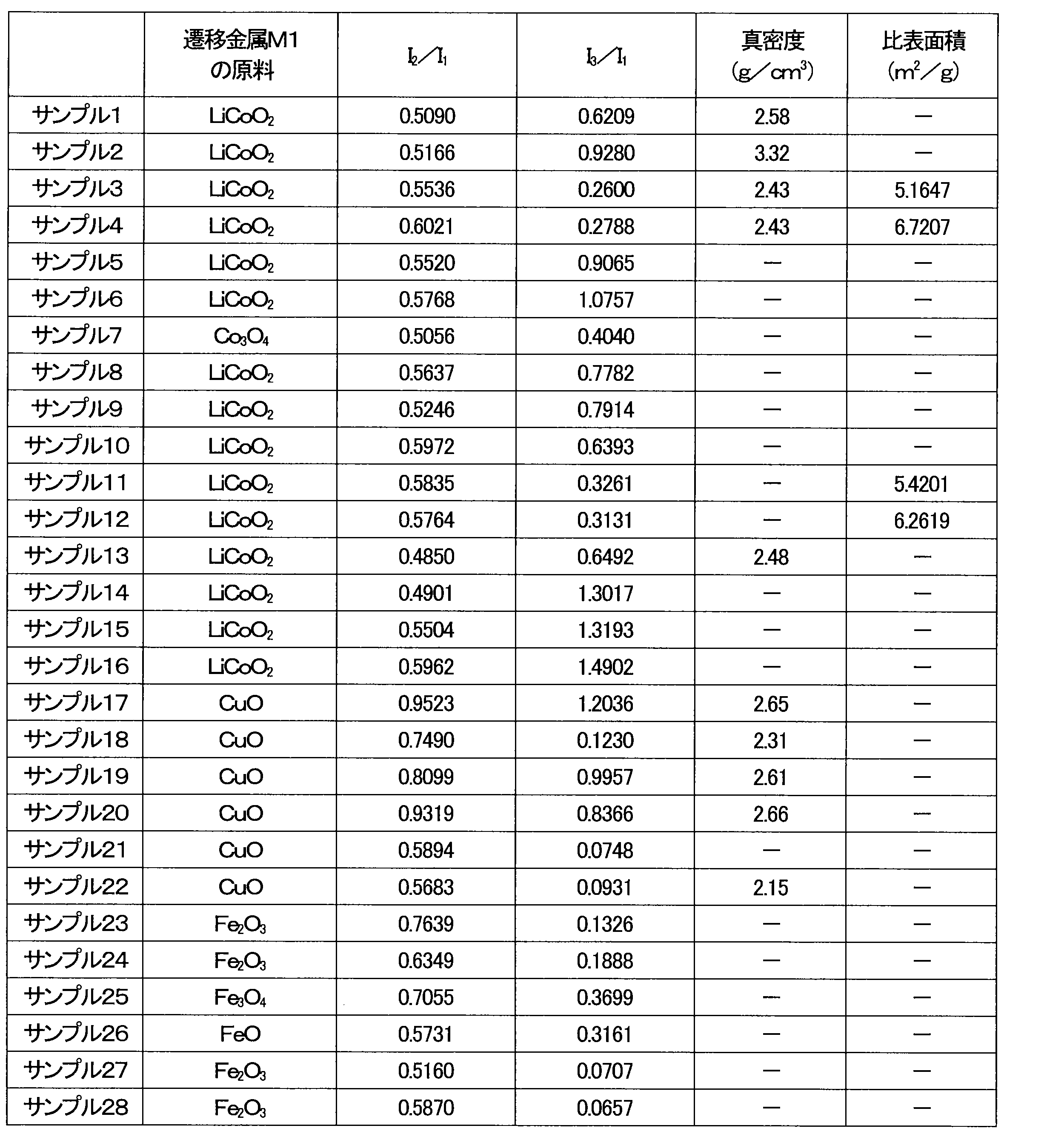
図3Aは、サンプル3の正極活物質のSEM像を示す。図3Bは、サンプル17の正極活物質のSEM像を示す。これらのSEM像から理解できるように、サンプル3及びサンプル17の正極活物質は、二次粒子の構造を有していた。他のサンプルの正極活物質についても同様の二次粒子の構造を有していた。
サンプル1から4、サンプル13、サンプル17から20及びサンプル22の正極活物質の真密度をピクノメータ法で測定した。
サンプル3、サンプル4、サンプル11及びサンプル12の正極活物質の比表面積をBET法で測定した。
サンプル1から28の正極活物質を用いてサンプル1から28のCR2016規格のコイン電池を作製した。正極には、正極活物質、アセチレンブラック及びポリテトラフルオロエチレンを7:2:1の質量比で含む正極合材を用いた。負極には厚さ0.3mmのリチウム金属箔を用いた。セパレータには、不織布/ポリオレフィン樹脂フィルム/不織布の三層セパレータを用いた。サンプル13-1、サンプル13-2及びサンプル13-3の電池は、サンプル13の正極活物質を用いた同一のコイン電池であり、充放電試験の条件を互いに異ならせたものである。

(サンプル1)
上限電圧を3.5V、充電容量の上限を647mAh/gに定め、64.7mA/gの電流値にて、サンプル1の電池を充電した。充電容量、500mAh/gでの電圧、及び、600mAh/gでの電圧を表3に示す。20分間休止した後、64.7mA/gの電流値で1.0Vまで定電流放電を行った。2.2V、2.0V、1.8V、1.5Vの各電圧での放電容量を表3に示す。
上限電圧を3.5V、充電容量の上限を647mAh/gに定め、64.7mA/gの電流値にて、サンプル14の電池を充電した。充電容量、500mAh/gでの電圧、及び、600mAh/gでの電圧を表3に示す。20分間休止した後、64.7mA/gの電流値で1.5Vまで定電流放電を行った。2.2V、2.0V、1.8V、1.5Vの各電圧での放電容量を表3に示す。

サンプル1と同じ条件でサンプル2の電池の充放電試験を行った。結果を表4に示す。
上限電圧を3.4V、充電容量の上限を600mAh/gに定め、50.0mA/gの電流値にて、サンプル3の電池を充電した。充電容量、500mAh/gでの電圧、及び、600mAh/gでの電圧を表4に示す。20分間休止した後、50.0mA/gの電流値で1.8Vまで定電流放電を行った。その後、1.8Vの定電圧で電流値が5mA/gに達するまで放電を行った。2.2V、2.0V、1.8Vの各電圧での放電容量を表4に示す。
上限電圧を3.4V、充電容量の上限を600mAh/gに定め、50.0mA/gの電流値にて、サンプル4の電池を充電した。充電容量、500mAh/gでの電圧、及び、600mAh/gでの電圧を表4に示す。20分間休止した後、50.0mA/gの電流値で1.5Vまで定電流放電を行った。その後、1.5Vでの定電圧放電を66時間行った。2.2V、2.0V、1.8V、1.5Vの各電圧での放電容量を表4に示す。

上限電圧を3.4V、下限電圧を1.5V、1サイクル目の充放電容量の上限を300mAh/g、2サイクル目の充放電容量の上限を400mAh/g、3サイクル目の充放電容量の上限を500mAh/gに定め、50.0mA/gの電流値にて、サンプル5から7、サンプル15及びサンプル16の電池を充放電させた。充電過程から放電過程に移行する際の休止時間は20分間であった。放電過程において所定容量に到達する前に1.5Vに到達した場合、1.5Vでの定電圧放電を1時間行った。3サイクル目の充電容量、及び、3サイクル目の充電時の500mAh/gでの電圧を表5に示す。3サイクル目の放電時における2.5V、2.2V、2.0V、1.8V、1.5Vの各電圧での放電容量を表5に示す。
上限電圧を3.4V、下限電圧を1.8V、1サイクル目の充放電容量の上限を300mAh/g、2サイクル目の充放電容量の上限を400mAh/g、3サイクル目の充放電容量の上限を500mAh/gに定め、50.0mA/gの電流値にて、サンプル8の電池を充放電させた。充電過程から放電過程に移行する際の休止時間は20分間であった。放電過程において所定容量に到達する前に電圧は1.8Vに到達しなかった。3サイクル目の充電容量、及び、3サイクル目の充電時の500mAh/gでの電圧を表5に示す。3サイクル目の放電時における2.5V、2.2V、2.0V、1.8Vの各電圧での放電容量を表5に示す。
上限電圧を3.4V、下限電圧を1.8V、1サイクル目の充放電容量の上限を300mAh/g、2サイクル目の充放電容量の上限を400mAh/g、3サイクル目の充放電容量の上限を500mAh/gに定め、50.0mA/gの電流値にて、サンプル9の電池を充放電させた。充電過程から放電過程に移行する際の休止時間は20分間であった。放電過程において所定容量に到達する前に1.8Vに到達した場合、1.8Vでの定電圧放電を実施し、電流値5mA/gの電流値に達するまで放電を行った。3サイクル目の充電容量、及び、3サイクル目の充電時の500mAh/gでの電圧を表5に示す。3サイクル目の放電時における2.5V、2.2V、2.0V、1.8Vの各電圧での放電容量を表5に示す。
上限電圧を3.4V、下限電圧を1.8V、1サイクル目の充放電容量の上限を300mAh/g、2サイクル目の充放電容量の上限を400mAh/g、3サイクル目の充放電容量の上限を500mAh/gに定め、50.0mA/gの電流値にて、サンプル10の電池を充放電させた。充電過程から放電過程に移行する際の休止時間は20分間であった。放電過程において所定容量に到達する前に電圧は1.8Vに到達しなかった。3サイクル目の充電容量、及び、3サイクル目の充電時の500mAh/gでの電圧を表5に示す。3サイクル目の放電時における2.5V、2.2V、2.0V、1.8Vの各電圧での放電容量を表5に示す。
上限電圧を3.4V、下限電圧を1.8V、1サイクル目の充放電容量の上限を300mAh/g、2サイクル目の充放電容量の上限を500mAh/g、3サイクル目の充放電容量の上限を600mAh/g、4サイクル目の充放電容量の上限を700mAh/gに定め、50.0mA/gの電流値にて、サンプル11及び12の電池を充放電させた。充電過程から放電過程に移行する際の休止時間は20分間であった。放電過程において所定容量に到達する前に電圧は1.8Vに到達しなかった。2サイクル目の充電容量、及び、2サイクル目の充電時の500mAh/gでの電圧を表5に示す。2サイクル目の放電時における2.5V、2.2V、2.0V、1.8Vの各電圧での放電容量を表5に示す。
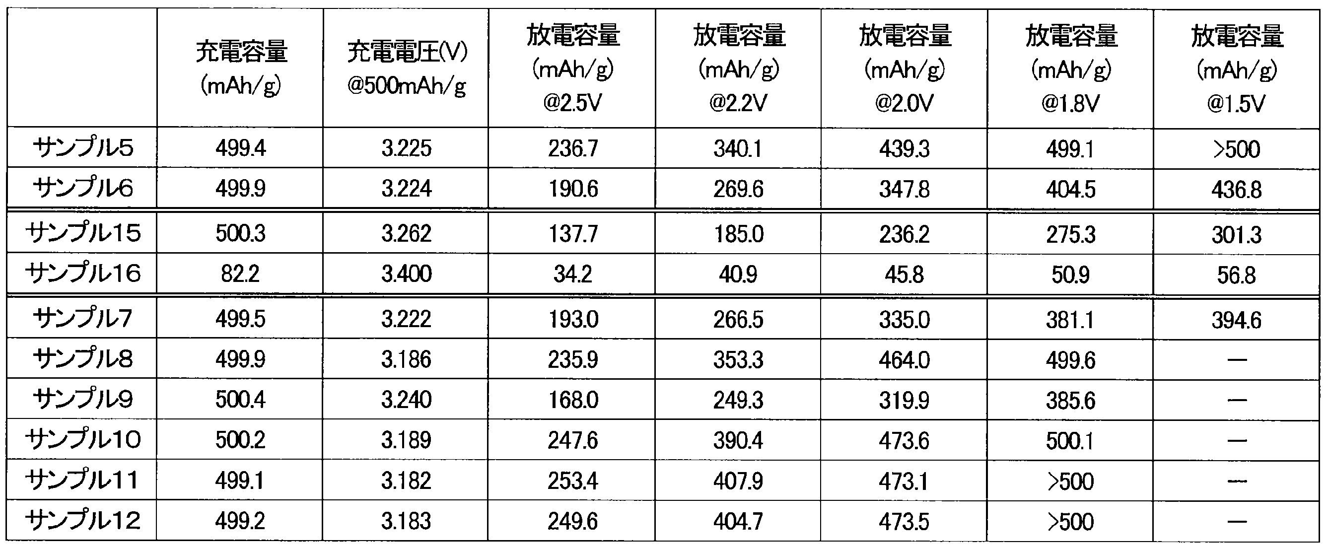
上限電圧を3.4V、充電容量の上限を600mAh/gに定め、50.0mA/gの電流値にて、サンプル13-1の電池を充電した。充電容量、500mAh/gでの電圧、及び、600mAh/gでの電圧を表6Aに示す。20分間休止した後、50.0mA/gの電流値で1.5Vまで定電流放電を行った。その後、5mA/gに達するまで、又は、24時間経過するまで1.5Vで定電圧放電を行った。2.2V、2.0V、1.8V、1.5Vの各電圧での放電容量を表6Aに示す。
上限電圧を3.4V、充電容量の上限を647mAh/gに定め、64.7mA/gの電流値にて、サンプル13-1の電池を充電した。充電容量、500mAh/gでの電圧、及び、600mAh/gでの電圧を表6Aに示す。20分間休止した後、50.0mA/gの電流値で1.5Vまで定電流放電を行った。その後、5mA/gに達するまで、又は、24時間経過するまで1.5Vで定電圧放電を行った。2.2V、2.0V、1.8V、1.5Vの各電圧での放電容量を表6Aに示す。

上限電圧を3.4V、下限電圧を1.8V、1サイクル目の充放電容量の上限を300mAh/g、2サイクル目の充放電容量の上限を400mAh/g、3サイクル目の充放電容量の上限を500mAh/g、4サイクル目の充放電容量の上限を600mAh/g、5サイクル目の充放電容量の上限を700mAh/gに定め、50.0mA/gの電流値にて、サンプル13-3の電池を充放電させた。充電過程から放電過程に移行する際の休止時間は20分間であった。3サイクル目の充電容量、3サイクル目の充電時の500mAh/gでの電圧、3サイクル目の放電時における2.5V、2.2V、2.0V、1.8Vの各電圧での放電容量を表6Bに示す。5サイクル目の充電容量、5サイクル目の充電時の700mAh/gでの電圧、5サイクル目の放電時における2.5V、2.2V、2.0V、1.8Vの各電圧での放電容量を表6Cに示す。


上限電圧を3.4V、充電容量の上限を533mAh/gに定め、53.3mA/gの電流値にて、サンプル20の電池を充電した。20分間休止した後、53.3mA/gの電流値で1.0Vまで定電流放電を行った。このサイクルを3回繰り返した。3サイクル目の充電容量、及び、3サイクル目の充電時の200mAh/gでの電圧を表7Aに示す。3サイクル目の放電時における2.2V、2.0V、1.8V、1.5Vの各電圧での放電容量を表7Aに示す。
上限電圧を3.4V、下限電圧を1.5V、1サイクル目の充放電容量の上限を300mAh/g、2サイクル目の充放電容量の上限を400mAh/g、3サイクル目の充放電容量の上限を500mAh/gに定め、50.0mA/gの電流値にて、サンプル17から20及びサンプル22の電池を充放電させた。充電過程から放電過程に移行する際の休止時間は20分間であった。放電過程において所定容量に到達する前に1.5Vに到達した場合、1.5Vでの定電圧放電を1時間行った。3サイクル目の充電容量、及び、3サイクル目の各容量での電圧を表7Aに示す。3サイクル目の放電時における2.5V、2.2V、2.0V、1.8V、1.5Vの各電圧での放電容量を表7Bに示す。
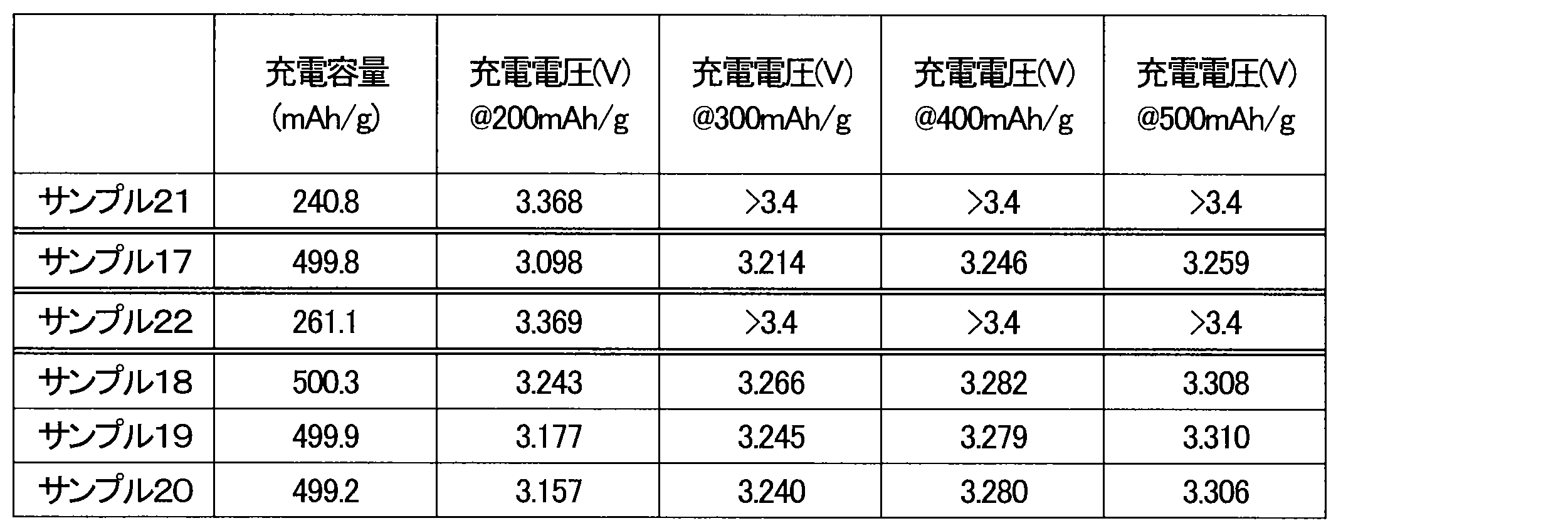
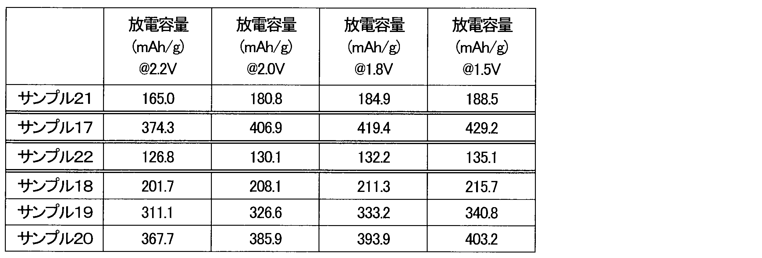
上限電圧を3.4V、充電容量の上限を300mAh/gに定め、50.0mA/gの電流値にて、サンプル23から28の電池を充電した。充電容量、200mAh/gでの電圧、及び、300mAh/gでの電圧を表8に示す。20分間休止した後、50.0mA/gの電流値で1.5V(サンプル26では1.8V)まで定電流放電を行った。その後、1.5V(サンプル26では1.8V)での定電圧放電を1時間行った。2.2V、2.0V、1.8V、1.5Vの各電圧での放電容量を表8に示す。
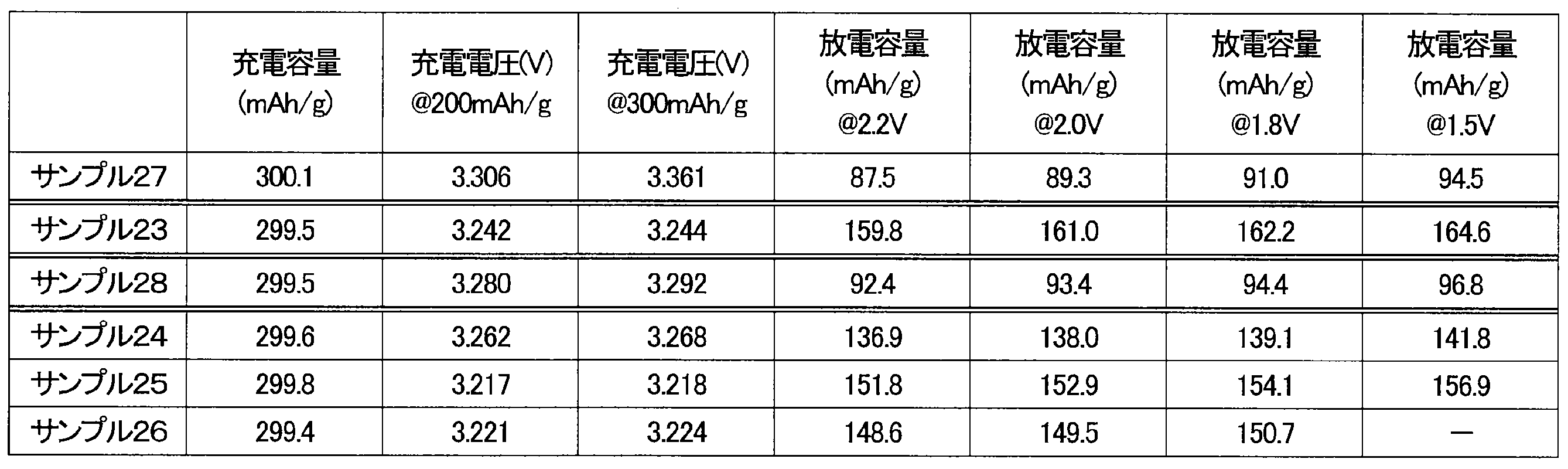
Claims (13)
- 正極、負極、セパレータ及び電解液を備え、
前記正極は、逆ホタル石型結晶構造を有し、かつ、遷移金属が固溶した酸化リチウムを正極活物質として含み、
前記電解液は、2種類以上のフッ素含有リチウム塩を含む、
電池。 - 前記2種類以上のフッ素含有リチウム塩が第1リチウム塩及び第2リチウム塩を含み、
前記第1リチウム塩は、フッ素化ホウ酸リチウム及びフッ素化リン酸リチウムからなる群より選ばれる少なくとも1つを含む、
請求項1に記載の電池。 - 前記フッ素化ホウ酸リチウムは、中心原子であるホウ素原子に少なくとも1つの酸素原子が結合した構造を有する、
請求項2に記載の電池。 - 前記フッ素化ホウ酸リチウムがジフルオロ(オキサラト)ホウ酸リチウムを含む、
請求項2に記載の電池。 - 前記電解液におけるフッ素化ホウ酸リチウムの濃度が0.32mol/リットル以上1.60mol/リットル以下である、
請求項2に記載の電池。 - 前記フッ素化リン酸リチウムは、中心原子であるリン原子に少なくとも1つの酸素原子が結合した構造を有する、
請求項2に記載の電池。 - 前記フッ素化リン酸リチウムがジフルオロリン酸リチウムを含む、
請求項2に記載の電池。 - 前記電解液におけるフッ素化リン酸リチウムの濃度が0.08mol/リットル以上0.32mol/リットル以下である、
請求項2に記載の電池。 - 前記第2リチウム塩がヘキサフルオロリン酸リチウムを含む、
請求項2に記載の電池。 - 前記正極活物質が粒子状の形状を有し、
前記正極活物質の粒子が0.01μm2以上500μm2以下の断面積を有する、
請求項1に記載の電池。 - 前記負極がリチウム金属を含む、
請求項1に記載の電池。 - 前記正極活物質は、遷移金属M2を含む遷移金属酸化物を更に含み、
Cu-Kα線を用いて測定された前記正極活物質のX線回折パターンにおいて、
30°から40°の回折角2θの範囲に存在する前記酸化リチウムの(111)面に帰属される第1の回折ピークの積分強度に対する、52°から62°の前記回折角2θの範囲に存在する前記酸化リチウムの(220)面に帰属される第2の回折ピークの積分強度の比が0.48以上であり、
前記第1の回折ピークの前記積分強度に対する、40°から50°の前記回折角2θの範囲に存在する前記遷移金属酸化物の結晶面に帰属される第3の回折ピークの積分強度の比が0.10以上1.30以下である、
請求項1に記載の電池。 - 前記正極活物質は、前記酸化リチウムの複数の一次粒子及び前記遷移金属酸化物の複数の一次粒子から構成される二次粒子の構造を有する、
請求項12に記載の電池。
Priority Applications (3)
| Application Number | Priority Date | Filing Date | Title |
|---|---|---|---|
| EP24750057.2A EP4661133A1 (en) | 2023-01-31 | 2024-01-23 | Battery |
| CN202480010122.0A CN120604369A (zh) | 2023-01-31 | 2024-01-23 | 电池 |
| JP2024574474A JPWO2024162106A1 (ja) | 2023-01-31 | 2024-01-23 |
Applications Claiming Priority (2)
| Application Number | Priority Date | Filing Date | Title |
|---|---|---|---|
| JP2023013533 | 2023-01-31 | ||
| JP2023-013533 | 2023-01-31 |
Publications (1)
| Publication Number | Publication Date |
|---|---|
| WO2024162106A1 true WO2024162106A1 (ja) | 2024-08-08 |
Family
ID=92146506
Family Applications (1)
| Application Number | Title | Priority Date | Filing Date |
|---|---|---|---|
| PCT/JP2024/001913 Ceased WO2024162106A1 (ja) | 2023-01-31 | 2024-01-23 | 電池 |
Country Status (4)
| Country | Link |
|---|---|
| EP (1) | EP4661133A1 (ja) |
| JP (1) | JPWO2024162106A1 (ja) |
| CN (1) | CN120604369A (ja) |
| WO (1) | WO2024162106A1 (ja) |
Citations (5)
| Publication number | Priority date | Publication date | Assignee | Title |
|---|---|---|---|---|
| JP2001345118A (ja) * | 2000-05-31 | 2001-12-14 | Yuasa Corp | 非水電解質電池 |
| JP2005506272A (ja) * | 2001-10-25 | 2005-03-03 | ソントル ナショナル ド ラ ルシェルシュ ションティフィーク | 酸化リチウム・バナジウム、その調製プロセス、及び、電極活物質としてのその利用 |
| WO2013051309A1 (ja) * | 2011-10-07 | 2013-04-11 | トヨタ自動車株式会社 | リチウム空気電池用の電解液 |
| JP2016539464A (ja) * | 2013-10-31 | 2016-12-15 | ショット アクチエンゲゼルシャフトSchott AG | 充電式リチウムイオン蓄電池 |
| WO2020202844A1 (ja) * | 2019-03-29 | 2020-10-08 | パナソニックIpマネジメント株式会社 | リチウム二次電池 |
Family Cites Families (2)
| Publication number | Priority date | Publication date | Assignee | Title |
|---|---|---|---|---|
| US6991876B2 (en) | 2001-10-05 | 2006-01-31 | Sri International | Metal/active oxygen batteries |
| JP6179944B2 (ja) | 2013-08-05 | 2017-08-16 | 国立大学法人 東京大学 | 遷移金属固溶アルカリ金属化合物 |
-
2024
- 2024-01-23 EP EP24750057.2A patent/EP4661133A1/en active Pending
- 2024-01-23 CN CN202480010122.0A patent/CN120604369A/zh active Pending
- 2024-01-23 JP JP2024574474A patent/JPWO2024162106A1/ja active Pending
- 2024-01-23 WO PCT/JP2024/001913 patent/WO2024162106A1/ja not_active Ceased
Patent Citations (5)
| Publication number | Priority date | Publication date | Assignee | Title |
|---|---|---|---|---|
| JP2001345118A (ja) * | 2000-05-31 | 2001-12-14 | Yuasa Corp | 非水電解質電池 |
| JP2005506272A (ja) * | 2001-10-25 | 2005-03-03 | ソントル ナショナル ド ラ ルシェルシュ ションティフィーク | 酸化リチウム・バナジウム、その調製プロセス、及び、電極活物質としてのその利用 |
| WO2013051309A1 (ja) * | 2011-10-07 | 2013-04-11 | トヨタ自動車株式会社 | リチウム空気電池用の電解液 |
| JP2016539464A (ja) * | 2013-10-31 | 2016-12-15 | ショット アクチエンゲゼルシャフトSchott AG | 充電式リチウムイオン蓄電池 |
| WO2020202844A1 (ja) * | 2019-03-29 | 2020-10-08 | パナソニックIpマネジメント株式会社 | リチウム二次電池 |
Non-Patent Citations (1)
| Title |
|---|
| See also references of EP4661133A1 * |
Also Published As
| Publication number | Publication date |
|---|---|
| EP4661133A1 (en) | 2025-12-10 |
| CN120604369A (zh) | 2025-09-05 |
| JPWO2024162106A1 (ja) | 2024-08-08 |
Similar Documents
| Publication | Publication Date | Title |
|---|---|---|
| US20200373570A1 (en) | Li4Ti5O12, Li(4-a)ZaTi5O12 OR Li4ZßTi(5-ß)O12, PARTICLES, PROCESSES FOR OBTAINING SAME AND USE AS ELECTROCHEMICAL GENERATORS | |
| EP2203948B1 (en) | Positive electrode active material, lithium secondary battery, and manufacture methods therefore | |
| KR20240128664A (ko) | 충전식 리튬이온전지용 음극재료, 이의 제조방법 및 사용방법 | |
| JP2024500147A (ja) | リチウムイオン二次電池用金属系-炭素系複合負極材、その製造方法およびこれを含む二次電池 | |
| JP2001319653A (ja) | 非水二次電池 | |
| KR101044577B1 (ko) | 고전압 리튬 이차 전지 | |
| WO2024162106A1 (ja) | 電池 | |
| WO2024162104A1 (ja) | 電池 | |
| WO2024162105A1 (ja) | 電池 | |
| WO2024162103A1 (ja) | 電池 | |
| WO2024162107A1 (ja) | 正極活物質及び電池 | |
| WO2024166676A1 (ja) | 電池 | |
| WO2025004765A1 (ja) | 正極活物質及び電池 | |
| WO2025164423A1 (ja) | 電池 | |
| WO2025204716A1 (ja) | 正極活物質、正極及び電池 | |
| WO2024181142A1 (ja) | 電極、および電池 | |
| DE102024134171A1 (de) | Mit mehreren Elementen dotiertes Kathodenmaterial | |
| WO2024142569A1 (ja) | 被覆正極活物質及びそれを用いた電池 | |
| WO2024247830A1 (ja) | 負極材料用複合粒子、および二次電池 | |
| WO2025089288A1 (ja) | 負極活物質、および二次電池 | |
| WO2025089289A1 (ja) | 負極活物質、および二次電池 | |
| JP2025132333A (ja) | 非水電解液および電気化学素子 |
Legal Events
| Date | Code | Title | Description |
|---|---|---|---|
| 121 | Ep: the epo has been informed by wipo that ep was designated in this application |
Ref document number: 24750057 Country of ref document: EP Kind code of ref document: A1 |
|
| ENP | Entry into the national phase |
Ref document number: 2024574474 Country of ref document: JP Kind code of ref document: A |
|
| WWE | Wipo information: entry into national phase |
Ref document number: 2024574474 Country of ref document: JP |
|
| WWE | Wipo information: entry into national phase |
Ref document number: 202480010122.0 Country of ref document: CN |
|
| WWE | Wipo information: entry into national phase |
Ref document number: 202547080695 Country of ref document: IN |
|
| NENP | Non-entry into the national phase |
Ref country code: DE |
|
| WWP | Wipo information: published in national office |
Ref document number: 202480010122.0 Country of ref document: CN |
|
| WWP | Wipo information: published in national office |
Ref document number: 202547080695 Country of ref document: IN |
|
| WWP | Wipo information: published in national office |
Ref document number: 2024750057 Country of ref document: EP |