WO2024162447A1 - 方向性電磁鋼板の製造方法 - Google Patents
方向性電磁鋼板の製造方法 Download PDFInfo
- Publication number
- WO2024162447A1 WO2024162447A1 PCT/JP2024/003357 JP2024003357W WO2024162447A1 WO 2024162447 A1 WO2024162447 A1 WO 2024162447A1 JP 2024003357 W JP2024003357 W JP 2024003357W WO 2024162447 A1 WO2024162447 A1 WO 2024162447A1
- Authority
- WO
- WIPO (PCT)
- Prior art keywords
- coil
- annealing
- sheet
- heating rate
- oriented electrical
- Prior art date
- Legal status (The legal status is an assumption and is not a legal conclusion. Google has not performed a legal analysis and makes no representation as to the accuracy of the status listed.)
- Ceased
Links
Classifications
-
- C—CHEMISTRY; METALLURGY
- C21—METALLURGY OF IRON
- C21D—MODIFYING THE PHYSICAL STRUCTURE OF FERROUS METALS; GENERAL DEVICES FOR HEAT TREATMENT OF FERROUS OR NON-FERROUS METALS OR ALLOYS; MAKING METAL MALLEABLE, e.g. BY DECARBURISATION OR TEMPERING
- C21D8/00—Modifying the physical properties of ferrous metals or ferrous alloys by deformation combined with, or followed by, heat treatment
- C21D8/12—Modifying the physical properties of ferrous metals or ferrous alloys by deformation combined with, or followed by, heat treatment during manufacturing of articles with special electromagnetic properties
- C21D8/1244—Modifying the physical properties of ferrous metals or ferrous alloys by deformation combined with, or followed by, heat treatment during manufacturing of articles with special electromagnetic properties characterised by the heat treatment
- C21D8/1272—Final recrystallisation annealing
-
- C—CHEMISTRY; METALLURGY
- C21—METALLURGY OF IRON
- C21D—MODIFYING THE PHYSICAL STRUCTURE OF FERROUS METALS; GENERAL DEVICES FOR HEAT TREATMENT OF FERROUS OR NON-FERROUS METALS OR ALLOYS; MAKING METAL MALLEABLE, e.g. BY DECARBURISATION OR TEMPERING
- C21D1/00—General methods or devices for heat treatment, e.g. annealing, hardening, quenching or tempering
- C21D1/26—Methods of annealing
-
- C—CHEMISTRY; METALLURGY
- C21—METALLURGY OF IRON
- C21D—MODIFYING THE PHYSICAL STRUCTURE OF FERROUS METALS; GENERAL DEVICES FOR HEAT TREATMENT OF FERROUS OR NON-FERROUS METALS OR ALLOYS; MAKING METAL MALLEABLE, e.g. BY DECARBURISATION OR TEMPERING
- C21D1/00—General methods or devices for heat treatment, e.g. annealing, hardening, quenching or tempering
- C21D1/74—Methods of treatment in inert gas, controlled atmosphere, vacuum or pulverulent material
- C21D1/76—Adjusting the composition of the atmosphere
-
- C—CHEMISTRY; METALLURGY
- C21—METALLURGY OF IRON
- C21D—MODIFYING THE PHYSICAL STRUCTURE OF FERROUS METALS; GENERAL DEVICES FOR HEAT TREATMENT OF FERROUS OR NON-FERROUS METALS OR ALLOYS; MAKING METAL MALLEABLE, e.g. BY DECARBURISATION OR TEMPERING
- C21D3/00—Diffusion processes for extraction of non-metals; Furnaces therefor
- C21D3/02—Extraction of non-metals
- C21D3/04—Decarburising
-
- C—CHEMISTRY; METALLURGY
- C21—METALLURGY OF IRON
- C21D—MODIFYING THE PHYSICAL STRUCTURE OF FERROUS METALS; GENERAL DEVICES FOR HEAT TREATMENT OF FERROUS OR NON-FERROUS METALS OR ALLOYS; MAKING METAL MALLEABLE, e.g. BY DECARBURISATION OR TEMPERING
- C21D6/00—Heat treatment of ferrous alloys
- C21D6/008—Heat treatment of ferrous alloys containing Si
-
- C—CHEMISTRY; METALLURGY
- C21—METALLURGY OF IRON
- C21D—MODIFYING THE PHYSICAL STRUCTURE OF FERROUS METALS; GENERAL DEVICES FOR HEAT TREATMENT OF FERROUS OR NON-FERROUS METALS OR ALLOYS; MAKING METAL MALLEABLE, e.g. BY DECARBURISATION OR TEMPERING
- C21D8/00—Modifying the physical properties of ferrous metals or ferrous alloys by deformation combined with, or followed by, heat treatment
- C21D8/12—Modifying the physical properties of ferrous metals or ferrous alloys by deformation combined with, or followed by, heat treatment during manufacturing of articles with special electromagnetic properties
- C21D8/1216—Modifying the physical properties of ferrous metals or ferrous alloys by deformation combined with, or followed by, heat treatment during manufacturing of articles with special electromagnetic properties characterised by the working steps
- C21D8/1222—Hot rolling
-
- C—CHEMISTRY; METALLURGY
- C21—METALLURGY OF IRON
- C21D—MODIFYING THE PHYSICAL STRUCTURE OF FERROUS METALS; GENERAL DEVICES FOR HEAT TREATMENT OF FERROUS OR NON-FERROUS METALS OR ALLOYS; MAKING METAL MALLEABLE, e.g. BY DECARBURISATION OR TEMPERING
- C21D8/00—Modifying the physical properties of ferrous metals or ferrous alloys by deformation combined with, or followed by, heat treatment
- C21D8/12—Modifying the physical properties of ferrous metals or ferrous alloys by deformation combined with, or followed by, heat treatment during manufacturing of articles with special electromagnetic properties
- C21D8/1244—Modifying the physical properties of ferrous metals or ferrous alloys by deformation combined with, or followed by, heat treatment during manufacturing of articles with special electromagnetic properties characterised by the heat treatment
- C21D8/1255—Modifying the physical properties of ferrous metals or ferrous alloys by deformation combined with, or followed by, heat treatment during manufacturing of articles with special electromagnetic properties characterised by the heat treatment with diffusion of elements, e.g. decarburising, nitriding
-
- C—CHEMISTRY; METALLURGY
- C21—METALLURGY OF IRON
- C21D—MODIFYING THE PHYSICAL STRUCTURE OF FERROUS METALS; GENERAL DEVICES FOR HEAT TREATMENT OF FERROUS OR NON-FERROUS METALS OR ALLOYS; MAKING METAL MALLEABLE, e.g. BY DECARBURISATION OR TEMPERING
- C21D8/00—Modifying the physical properties of ferrous metals or ferrous alloys by deformation combined with, or followed by, heat treatment
- C21D8/12—Modifying the physical properties of ferrous metals or ferrous alloys by deformation combined with, or followed by, heat treatment during manufacturing of articles with special electromagnetic properties
- C21D8/1244—Modifying the physical properties of ferrous metals or ferrous alloys by deformation combined with, or followed by, heat treatment during manufacturing of articles with special electromagnetic properties characterised by the heat treatment
- C21D8/1261—Modifying the physical properties of ferrous metals or ferrous alloys by deformation combined with, or followed by, heat treatment during manufacturing of articles with special electromagnetic properties characterised by the heat treatment following hot rolling
-
- C—CHEMISTRY; METALLURGY
- C21—METALLURGY OF IRON
- C21D—MODIFYING THE PHYSICAL STRUCTURE OF FERROUS METALS; GENERAL DEVICES FOR HEAT TREATMENT OF FERROUS OR NON-FERROUS METALS OR ALLOYS; MAKING METAL MALLEABLE, e.g. BY DECARBURISATION OR TEMPERING
- C21D8/00—Modifying the physical properties of ferrous metals or ferrous alloys by deformation combined with, or followed by, heat treatment
- C21D8/12—Modifying the physical properties of ferrous metals or ferrous alloys by deformation combined with, or followed by, heat treatment during manufacturing of articles with special electromagnetic properties
- C21D8/1244—Modifying the physical properties of ferrous metals or ferrous alloys by deformation combined with, or followed by, heat treatment during manufacturing of articles with special electromagnetic properties characterised by the heat treatment
- C21D8/1266—Modifying the physical properties of ferrous metals or ferrous alloys by deformation combined with, or followed by, heat treatment during manufacturing of articles with special electromagnetic properties characterised by the heat treatment between cold rolling steps
-
- C—CHEMISTRY; METALLURGY
- C21—METALLURGY OF IRON
- C21D—MODIFYING THE PHYSICAL STRUCTURE OF FERROUS METALS; GENERAL DEVICES FOR HEAT TREATMENT OF FERROUS OR NON-FERROUS METALS OR ALLOYS; MAKING METAL MALLEABLE, e.g. BY DECARBURISATION OR TEMPERING
- C21D8/00—Modifying the physical properties of ferrous metals or ferrous alloys by deformation combined with, or followed by, heat treatment
- C21D8/12—Modifying the physical properties of ferrous metals or ferrous alloys by deformation combined with, or followed by, heat treatment during manufacturing of articles with special electromagnetic properties
- C21D8/1277—Modifying the physical properties of ferrous metals or ferrous alloys by deformation combined with, or followed by, heat treatment during manufacturing of articles with special electromagnetic properties involving a particular surface treatment
- C21D8/1283—Application of a separating or insulating coating
-
- C—CHEMISTRY; METALLURGY
- C21—METALLURGY OF IRON
- C21D—MODIFYING THE PHYSICAL STRUCTURE OF FERROUS METALS; GENERAL DEVICES FOR HEAT TREATMENT OF FERROUS OR NON-FERROUS METALS OR ALLOYS; MAKING METAL MALLEABLE, e.g. BY DECARBURISATION OR TEMPERING
- C21D9/00—Heat treatment, e.g. annealing, hardening, quenching or tempering, adapted for particular articles; Furnaces therefor
- C21D9/46—Heat treatment, e.g. annealing, hardening, quenching or tempering, adapted for particular articles; Furnaces therefor for sheet metals
-
- C—CHEMISTRY; METALLURGY
- C22—METALLURGY; FERROUS OR NON-FERROUS ALLOYS; TREATMENT OF ALLOYS OR NON-FERROUS METALS
- C22C—ALLOYS
- C22C38/00—Ferrous alloys, e.g. steel alloys
- C22C38/002—Ferrous alloys, e.g. steel alloys containing In, Mg, or other elements not provided for in one single group C22C38/001 - C22C38/60
-
- C—CHEMISTRY; METALLURGY
- C22—METALLURGY; FERROUS OR NON-FERROUS ALLOYS; TREATMENT OF ALLOYS OR NON-FERROUS METALS
- C22C—ALLOYS
- C22C38/00—Ferrous alloys, e.g. steel alloys
- C22C38/004—Very low carbon steels, i.e. having a carbon content of less than 0,01%
-
- C—CHEMISTRY; METALLURGY
- C22—METALLURGY; FERROUS OR NON-FERROUS ALLOYS; TREATMENT OF ALLOYS OR NON-FERROUS METALS
- C22C—ALLOYS
- C22C38/00—Ferrous alloys, e.g. steel alloys
- C22C38/008—Ferrous alloys, e.g. steel alloys containing tin
-
- C—CHEMISTRY; METALLURGY
- C22—METALLURGY; FERROUS OR NON-FERROUS ALLOYS; TREATMENT OF ALLOYS OR NON-FERROUS METALS
- C22C—ALLOYS
- C22C38/00—Ferrous alloys, e.g. steel alloys
- C22C38/02—Ferrous alloys, e.g. steel alloys containing silicon
-
- C—CHEMISTRY; METALLURGY
- C22—METALLURGY; FERROUS OR NON-FERROUS ALLOYS; TREATMENT OF ALLOYS OR NON-FERROUS METALS
- C22C—ALLOYS
- C22C38/00—Ferrous alloys, e.g. steel alloys
- C22C38/04—Ferrous alloys, e.g. steel alloys containing manganese
-
- C—CHEMISTRY; METALLURGY
- C22—METALLURGY; FERROUS OR NON-FERROUS ALLOYS; TREATMENT OF ALLOYS OR NON-FERROUS METALS
- C22C—ALLOYS
- C22C38/00—Ferrous alloys, e.g. steel alloys
- C22C38/08—Ferrous alloys, e.g. steel alloys containing nickel
-
- C—CHEMISTRY; METALLURGY
- C22—METALLURGY; FERROUS OR NON-FERROUS ALLOYS; TREATMENT OF ALLOYS OR NON-FERROUS METALS
- C22C—ALLOYS
- C22C38/00—Ferrous alloys, e.g. steel alloys
- C22C38/12—Ferrous alloys, e.g. steel alloys containing tungsten, tantalum, molybdenum, vanadium, or niobium
-
- C—CHEMISTRY; METALLURGY
- C22—METALLURGY; FERROUS OR NON-FERROUS ALLOYS; TREATMENT OF ALLOYS OR NON-FERROUS METALS
- C22C—ALLOYS
- C22C38/00—Ferrous alloys, e.g. steel alloys
- C22C38/14—Ferrous alloys, e.g. steel alloys containing titanium or zirconium
-
- C—CHEMISTRY; METALLURGY
- C22—METALLURGY; FERROUS OR NON-FERROUS ALLOYS; TREATMENT OF ALLOYS OR NON-FERROUS METALS
- C22C—ALLOYS
- C22C38/00—Ferrous alloys, e.g. steel alloys
- C22C38/16—Ferrous alloys, e.g. steel alloys containing copper
-
- C—CHEMISTRY; METALLURGY
- C22—METALLURGY; FERROUS OR NON-FERROUS ALLOYS; TREATMENT OF ALLOYS OR NON-FERROUS METALS
- C22C—ALLOYS
- C22C38/00—Ferrous alloys, e.g. steel alloys
- C22C38/18—Ferrous alloys, e.g. steel alloys containing chromium
- C22C38/28—Ferrous alloys, e.g. steel alloys containing chromium with titanium or zirconium
-
- C—CHEMISTRY; METALLURGY
- C22—METALLURGY; FERROUS OR NON-FERROUS ALLOYS; TREATMENT OF ALLOYS OR NON-FERROUS METALS
- C22C—ALLOYS
- C22C38/00—Ferrous alloys, e.g. steel alloys
- C22C38/18—Ferrous alloys, e.g. steel alloys containing chromium
- C22C38/34—Ferrous alloys, e.g. steel alloys containing chromium with more than 1.5% by weight of silicon
-
- C—CHEMISTRY; METALLURGY
- C22—METALLURGY; FERROUS OR NON-FERROUS ALLOYS; TREATMENT OF ALLOYS OR NON-FERROUS METALS
- C22C—ALLOYS
- C22C38/00—Ferrous alloys, e.g. steel alloys
- C22C38/60—Ferrous alloys, e.g. steel alloys containing lead, selenium, tellurium, or antimony, or more than 0.04% by weight of sulfur
-
- H—ELECTRICITY
- H01—ELECTRIC ELEMENTS
- H01F—MAGNETS; INDUCTANCES; TRANSFORMERS; SELECTION OF MATERIALS FOR THEIR MAGNETIC PROPERTIES
- H01F1/00—Magnets or magnetic bodies characterised by the magnetic materials therefor; Selection of materials for their magnetic properties
- H01F1/01—Magnets or magnetic bodies characterised by the magnetic materials therefor; Selection of materials for their magnetic properties of inorganic materials
- H01F1/03—Magnets or magnetic bodies characterised by the magnetic materials therefor; Selection of materials for their magnetic properties of inorganic materials characterised by their coercivity
- H01F1/12—Magnets or magnetic bodies characterised by the magnetic materials therefor; Selection of materials for their magnetic properties of inorganic materials characterised by their coercivity of soft-magnetic materials
- H01F1/14—Magnets or magnetic bodies characterised by the magnetic materials therefor; Selection of materials for their magnetic properties of inorganic materials characterised by their coercivity of soft-magnetic materials metals or alloys
- H01F1/147—Alloys characterised by their composition
- H01F1/14766—Fe-Si based alloys
- H01F1/14775—Fe-Si based alloys in the form of sheets
-
- H—ELECTRICITY
- H01—ELECTRIC ELEMENTS
- H01F—MAGNETS; INDUCTANCES; TRANSFORMERS; SELECTION OF MATERIALS FOR THEIR MAGNETIC PROPERTIES
- H01F1/00—Magnets or magnetic bodies characterised by the magnetic materials therefor; Selection of materials for their magnetic properties
- H01F1/01—Magnets or magnetic bodies characterised by the magnetic materials therefor; Selection of materials for their magnetic properties of inorganic materials
- H01F1/03—Magnets or magnetic bodies characterised by the magnetic materials therefor; Selection of materials for their magnetic properties of inorganic materials characterised by their coercivity
- H01F1/12—Magnets or magnetic bodies characterised by the magnetic materials therefor; Selection of materials for their magnetic properties of inorganic materials characterised by their coercivity of soft-magnetic materials
- H01F1/14—Magnets or magnetic bodies characterised by the magnetic materials therefor; Selection of materials for their magnetic properties of inorganic materials characterised by their coercivity of soft-magnetic materials metals or alloys
- H01F1/147—Alloys characterised by their composition
- H01F1/14766—Fe-Si based alloys
- H01F1/14775—Fe-Si based alloys in the form of sheets
- H01F1/14783—Fe-Si based alloys in the form of sheets with insulating coating
-
- H—ELECTRICITY
- H01—ELECTRIC ELEMENTS
- H01F—MAGNETS; INDUCTANCES; TRANSFORMERS; SELECTION OF MATERIALS FOR THEIR MAGNETIC PROPERTIES
- H01F1/00—Magnets or magnetic bodies characterised by the magnetic materials therefor; Selection of materials for their magnetic properties
- H01F1/01—Magnets or magnetic bodies characterised by the magnetic materials therefor; Selection of materials for their magnetic properties of inorganic materials
- H01F1/03—Magnets or magnetic bodies characterised by the magnetic materials therefor; Selection of materials for their magnetic properties of inorganic materials characterised by their coercivity
- H01F1/12—Magnets or magnetic bodies characterised by the magnetic materials therefor; Selection of materials for their magnetic properties of inorganic materials characterised by their coercivity of soft-magnetic materials
- H01F1/14—Magnets or magnetic bodies characterised by the magnetic materials therefor; Selection of materials for their magnetic properties of inorganic materials characterised by their coercivity of soft-magnetic materials metals or alloys
- H01F1/147—Alloys characterised by their composition
- H01F1/14766—Fe-Si based alloys
- H01F1/14791—Fe-Si-Al based alloys, e.g. Sendust
-
- H—ELECTRICITY
- H01—ELECTRIC ELEMENTS
- H01F—MAGNETS; INDUCTANCES; TRANSFORMERS; SELECTION OF MATERIALS FOR THEIR MAGNETIC PROPERTIES
- H01F1/00—Magnets or magnetic bodies characterised by the magnetic materials therefor; Selection of materials for their magnetic properties
- H01F1/01—Magnets or magnetic bodies characterised by the magnetic materials therefor; Selection of materials for their magnetic properties of inorganic materials
- H01F1/03—Magnets or magnetic bodies characterised by the magnetic materials therefor; Selection of materials for their magnetic properties of inorganic materials characterised by their coercivity
- H01F1/12—Magnets or magnetic bodies characterised by the magnetic materials therefor; Selection of materials for their magnetic properties of inorganic materials characterised by their coercivity of soft-magnetic materials
- H01F1/14—Magnets or magnetic bodies characterised by the magnetic materials therefor; Selection of materials for their magnetic properties of inorganic materials characterised by their coercivity of soft-magnetic materials metals or alloys
- H01F1/16—Magnets or magnetic bodies characterised by the magnetic materials therefor; Selection of materials for their magnetic properties of inorganic materials characterised by their coercivity of soft-magnetic materials metals or alloys in the form of sheets
-
- C—CHEMISTRY; METALLURGY
- C21—METALLURGY OF IRON
- C21D—MODIFYING THE PHYSICAL STRUCTURE OF FERROUS METALS; GENERAL DEVICES FOR HEAT TREATMENT OF FERROUS OR NON-FERROUS METALS OR ALLOYS; MAKING METAL MALLEABLE, e.g. BY DECARBURISATION OR TEMPERING
- C21D2201/00—Treatment for obtaining particular effects
- C21D2201/05—Grain orientation
-
- Y—GENERAL TAGGING OF NEW TECHNOLOGICAL DEVELOPMENTS; GENERAL TAGGING OF CROSS-SECTIONAL TECHNOLOGIES SPANNING OVER SEVERAL SECTIONS OF THE IPC; TECHNICAL SUBJECTS COVERED BY FORMER USPC CROSS-REFERENCE ART COLLECTIONS [XRACs] AND DIGESTS
- Y02—TECHNOLOGIES OR APPLICATIONS FOR MITIGATION OR ADAPTATION AGAINST CLIMATE CHANGE
- Y02P—CLIMATE CHANGE MITIGATION TECHNOLOGIES IN THE PRODUCTION OR PROCESSING OF GOODS
- Y02P10/00—Technologies related to metal processing
- Y02P10/20—Recycling
Definitions
- the present invention relates to a method for manufacturing grain-oriented electrical steel sheets.
- Grain-oriented electrical steel sheet is a soft magnetic material that is mainly used for the iron cores of transformers and the like, and is required to have excellent magnetic properties, i.e. low iron loss and high magnetic flux density.
- Such grain-oriented electrical steel sheet is manufactured by utilizing the secondary recrystallization phenomenon to highly concentrate the ⁇ 110 ⁇ 001> orientation, also known as the Goss orientation.
- a method using an inhibitor has been used in the past.
- a steel slab containing inhibitor-forming components such as AlN, MnS, and MnSe is heated and then hot-rolled to obtain a hot-rolled sheet.
- the hot-rolled sheet is then annealed as necessary, and cold-rolled once or twice or more with intermediate annealing to obtain a cold-rolled sheet.
- the cold-rolled sheet is then decarburized annealed to obtain a decarburized annealed sheet.
- An annealing separator mainly made of MgO is then applied to the decarburized annealed sheet, and the decarburized annealed sheet is then wound up to obtain a coil. The coil is then finish-annealed.
- the steel slab is heated to a high temperature exceeding 1300°C to dissolve the inhibitor, which is then finely dispersed in a subsequent process to suppress the primary recrystallization grain growth, thereby causing secondary recrystallization (for example, Patent Document 1).
- the conventional method using an inhibitor requires the slab to be heated at a high temperature exceeding 1300°C, which results in high manufacturing costs and makes it difficult to meet the recent need for reducing manufacturing costs.
- inhibitorless method a method that does not use inhibitors (inhibitorless method) has been proposed (for example, Patent Document 2).
- this inhibitorless method secondary recrystallization is caused by reducing inhibitor-forming components and controlling the texture (assembly structure). Since the inhibitorless method does not require slab heating at high temperatures, production costs are low and it is possible to produce grain-oriented electrical steel sheets inexpensively.
- the inhibitorless method had the problem that the magnetic properties were not stable and varied across the length and width of the steel plate.
- Patent Document 3 proposes a method of controlling the shape and amount of carbides before cold rolling.
- Patent Document 4 proposes a method of controlling the balance between ⁇ 111 ⁇ oriented grains and ⁇ 411 ⁇ oriented grains in primary recrystallized grains.
- the present invention aims to provide a method for producing grain-oriented electrical steel sheets that can produce grain-oriented electrical steel sheets with uniformly excellent magnetic properties in both the longitudinal and transverse directions, even when using an inhibitorless method.
- the heating rate varies between the hottest point, which is the point in the coil where the temperature is the highest, and the coldest point, which is the point in the coil where the temperature is the lowest, causing variations in the magnetic properties within the steel sheet. Therefore, by reducing this variation in heating rate and keeping the heating rate within each temperature range within the preferred ranges at both the hottest point and the coldest point of the coil, it is possible to improve the variation in the magnetic properties within the steel sheet.
- composition further includes, in mass%, one or more selected from the group consisting of Se: 0.0001-0.0050%, B: 0.0001-0.0050%, P: 0.005-0.100%, Ti: 0.001-0.010%, Cr: 0.01-0.50%, Ni: 0.01-1.50%, Cu: 0.01-0.50%, Nb: 0.001-0.100%, Mo: 0.005-0.100%, Sn: 0.005-0.500%, Sb: 0.005-0.500%, and Bi: 0.001-0.050%.
- the steel slab was hot-rolled to obtain a hot-rolled sheet having a thickness of 2.0 mm. Then, the hot-rolled sheet was cold-rolled to obtain a cold-rolled sheet having a thickness of 0.22 mm. Next, the cold-rolled sheet was decarburized under the conditions of an H 2 +N 2 atmosphere, an oxidizing (PH 2 O/PH 2 ) of 0.3, an annealing temperature of 840° C., and a holding time at the annealing temperature of 120 seconds to obtain a decarburized annealed sheet.
- an annealing separator containing 2.0 parts by mass of TiO 2 and 100 parts by mass of MgO was applied to the surface of the decarburized annealed sheet, and then the decarburized annealed sheet was wound up to obtain a coil having a sheet width of 1100 mm and a thickness shown in Table 1.
- the coil was subjected to finish annealing.
- the heating rate H 1 from room temperature to 850 ° C. and the heating rate H 2 from 850 ° C. to 950 ° C. at the hottest point and the coldest point of the coil were the values shown in Table 1.
- the heating rate H 3 from 1000 ° C. to 1100 ° C. was 20.0 ° C. / h at the hottest point of the coil, and at this time, it was in the range of 12 ° C. / h to 18 ° C. / h at the coldest point of the coil.
- the coil was heated, and the finish annealing was performed under the condition that the hottest point reached 1200 ° C. and was held for 10 hours.
- the atmosphere in the finish annealing was an inert gas atmosphere at 950 ° C. or less, and an H 2 + N 2 mixed atmosphere at 950 ° C. or more.
- the positions of the hottest point and the coldest point of the coil are uniquely determined by heat transfer calculation from the furnace structure and the coil shape, etc. Therefore, the heating rates H 1 , H 2 and H 3 at the hottest and coldest points of the coil were actually measured by wrapping thermocouples at each position.
- test pieces were taken from the hottest and coldest points of the coil, and the magnetic properties (magnetic flux density B8 and iron loss W17/50 ) of each test piece were evaluated.
- the magnetic flux density B8 and iron loss W17/50 were measured according to JIS C 2550. The measurement results are shown in Table 1.
- the inventors consider the following. That is, in the inhibitorless method, the primary recrystallized grains are easily coarsened because the growth suppression force of the primary recrystallized grains is weak. Therefore, if the heating rate H1 is too slow, it takes a long time to reach the temperature range of about 850°C, which is the secondary recrystallization temperature range, and the primary recrystallized grains coarsen before the secondary recrystallization, and the driving force of the secondary recrystallization decreases. It is believed that this is the reason for the deterioration of the magnetic properties.
- the magnetic properties are more susceptible to the effect of the heating rate in the final annealing than in the conventional method that uses an inhibitor. For this reason, it is important to keep the heating rate up to the secondary recrystallization temperature range and the heating rate in the secondary recrystallization temperature range within their respective suitable ranges.
- the C is an effective component for improving the primary recrystallization texture. From the viewpoint of obtaining this effect, the C content is set to 0.010% or more, and preferably 0.020% or more. On the other hand, if the C content is too high, decarburization becomes difficult and the magnetic properties deteriorate. From this viewpoint, the C content is set to 0.100% or less, and preferably 0.080% or less.
- the Si is an effective component for increasing resistivity and improving magnetic properties. From the viewpoint of obtaining this effect, the Si content is set to 1.00% or more, and preferably 2.00% or more. On the other hand, if the Si content is too high, the cold rollability is significantly deteriorated. From this viewpoint, the Si content is set to 5.00% or less, and preferably 4.00% or less.
- Mn is an effective component for increasing resistivity, improving magnetic properties, and improving hot ductility. From the viewpoint of obtaining these effects, the Mn content is set to 0.010% or more, and preferably 0.020% or more. On the other hand, if the Mn content is too high, the magnetic properties deteriorate. From this viewpoint, the Mn content is set to 0.500% or less, and preferably 0.200% or less.
- the present invention relates to an inhibitorless method, it is necessary to suppress the contents of N, Al, and S, which are inhibitor-forming components, as much as possible.
- the N content must be less than 0.0050%
- the Al content must be less than 0.0100%
- the S content must be less than 0.0050%.
- the N content is preferably less than 0.0045%.
- the Al content is preferably less than 0.0080%.
- the S content is preferably less than 0.0040%.
- the N content is preferably 0.0010% or more.
- the Al content is preferably 0.0010% or more.
- the S content is preferably 0.0010% or more.
- the remainder other than the above components consists of Fe and unavoidable impurities, but the following elements may be added as desired. That is, for the purpose of further improving the magnetic properties, one or more elements selected from the group consisting of Se: 0.0001-0.0050%, B: 0.0001-0.0050%, P: 0.005-0.100%, Ti: 0.001-0.010%, Cr: 0.01-0.50%, Ni: 0.01-1.50%, Cu: 0.01-0.50%, Nb: 0.001-0.100%, Mo: 0.005-0.100%, Sn: 0.005-0.500%, Sb: 0.005-0.500%, and Bi: 0.001-0.050% may be added.
- the slab heating temperature is preferably in the range of 1000 to 1300°C. If the slab heating temperature is less than 1000°C, the hot ductility deteriorates. Furthermore, if an inhibitor is not used, a slab heating temperature exceeding 1300°C is no longer effective, and in addition to increasing manufacturing costs, the crystal grains become coarse, deteriorating the magnetic properties.
- the steel slab is hot rolled to obtain a hot-rolled sheet.
- the hot-rolled sheet is then annealed as necessary.
- the hot-rolled sheet is then cold rolled once or two or more times with intermediate annealing to obtain a cold-rolled sheet.
- the cold-rolled sheet is then subjected to decarburization annealing to obtain a decarburized annealed sheet.
- the annealing temperature during decarburization annealing is preferably in the range of 750 to 950°C
- the holding time at the annealing temperature is preferably in the range of 80 to 200 seconds. If the annealing temperature is 750°C or higher and the holding time is 80 seconds or longer, decarburization proceeds sufficiently. Furthermore, if the annealing temperature is 950°C or lower and the holding time is 200 seconds or shorter, the primary recrystallized grains do not become coarse, so secondary recrystallization is not suppressed and magnetic properties do not deteriorate.
- the atmosphere during decarburization annealing is preferably a H 2 +N 2 atmosphere.
- the oxidizing property (PH 2 O/PH 2 ) during decarburization annealing is preferably in the range of 0.1 to 0.6. If PH 2 O/PH 2 is 0.1 or more, decarburization proceeds sufficiently. Also, if PH 2 O/PH 2 is 0.6 or less, FeO is not formed and the coating properties are not deteriorated.
- the decarburized annealed sheet is coated with an annealing separator.
- Any known or arbitrary annealing separator mainly composed of MgO can be used as the annealing separator.
- additives consisting of one or more of oxides, hydroxides, borates, carbonates, nitrates, phosphates, sulfates, and halides of Li, Na, Mg, Al, Si, K, Ca, Ti, V, Fe, Co, Ni, Cu, Sr, Ba, and lanthanoids may be added to the annealing separator.
- the amount of additive added is preferably in the range of 0.01 to 15 parts by mass per 100 parts by mass of MgO. If the amount added is 0.01 part by mass or more, a sufficient effect of the addition can be obtained. Furthermore, if the amount added is 15 parts by mass or less, the magnetic properties will not deteriorate.
- the decarburized annealed sheet is then wound into a coil, which is then subjected to finish annealing.
- Finish annealing consists of secondary recrystallization annealing from room temperature to 950°C, followed by purification annealing at 1100-1300°C for 5-50 hours. Secondary recrystallization annealing is annealing to promote secondary recrystallization, and purification annealing is annealing to purify impurities.
- the heating rate H1 from room temperature to 850°C is 10.0°C/h or more at both the hottest point and the coldest point of the coil, and the heating rate H2 from 850°C to 950°C is 15.0°C/h or less. Since the coil temperature at the start of the finish annealing is room temperature, the heating rate H1 means the heating rate from the temperature at the time of the finish annealing to 850°C.
- the room temperature is not particularly limited and may be, for example, in the range of about -10°C to 50°C.
- the heating rate H1 is set to 10.0°C/h or more. There is no particular upper limit to the heating rate H1 , but industrially, the heating rate H1 may be 30.0°C/h or less.
- the heating rate H2 is set to 15.0°C/h or less.
- the lower limit of the heating rate H2 is not particularly limited, from the viewpoint of productivity, the heating rate H2 is preferably set to 2.0°C/h or more.
- the annealing atmosphere during the final annealing from room temperature to 950° C. is preferably an inert atmosphere of N 2 or Ar.
- the heating rate H3 from 1000°C to 1100°C is preferably 5.0°C/h or more and 30.0°C/h or less at both the hottest point and the coldest point of the coil. If the heating rate H3 is 5.0°C/h or more, the coating formation proceeds appropriately and excellent coating properties can be obtained. Also, if the heating rate H3 is 30.0°C/h or less, the coating formation is not excessive and the deterioration of the coating properties such as the occurrence of point defects is not caused.
- the annealing atmosphere at 950° C. or higher during the final annealing is preferably an H 2 +N 2 atmosphere.
- thermocouples can be wound around the hottest and coldest points of the coil to perform actual measurements, or a predictive model can be created from past finish annealing results and calculations can be performed from finish annealing conditions such as annealing temperature and time.
- the method for reducing the variation in heating rate between the hottest and coldest points of the coil is not particularly limited, but may be, for example, reducing the coil thickness, performing a soaking treatment before reaching the secondary recrystallization temperature range, or using a hearth heater to perform heating from the hearth closest to the coldest point of the coil.
- the method for reducing the coil thickness may be to simply reduce the mass of the coil, or to increase the outer and inner diameters of the coil without reducing the mass of the coil.
- the annealing temperature in purification annealing is preferably within the range of 1100-1300°C at the hottest point of the coil, and the holding time at the annealing temperature is preferably within the range of 5-50 hours. If the annealing temperature at the hottest point is 1100°C or higher and the holding time is 5 hours or longer, purification will proceed sufficiently, improving the magnetic properties. Also, if the annealing temperature at the hottest point is 1300°C or lower and the holding time is 50 hours or less, the coil will not buckle and the shape will not deteriorate.
- insulation coating, flattening annealing, and magnetic domain refinement processing are applied to produce grain-oriented electrical steel sheet.
- any items not described in this specification can be manufactured using conventional methods.
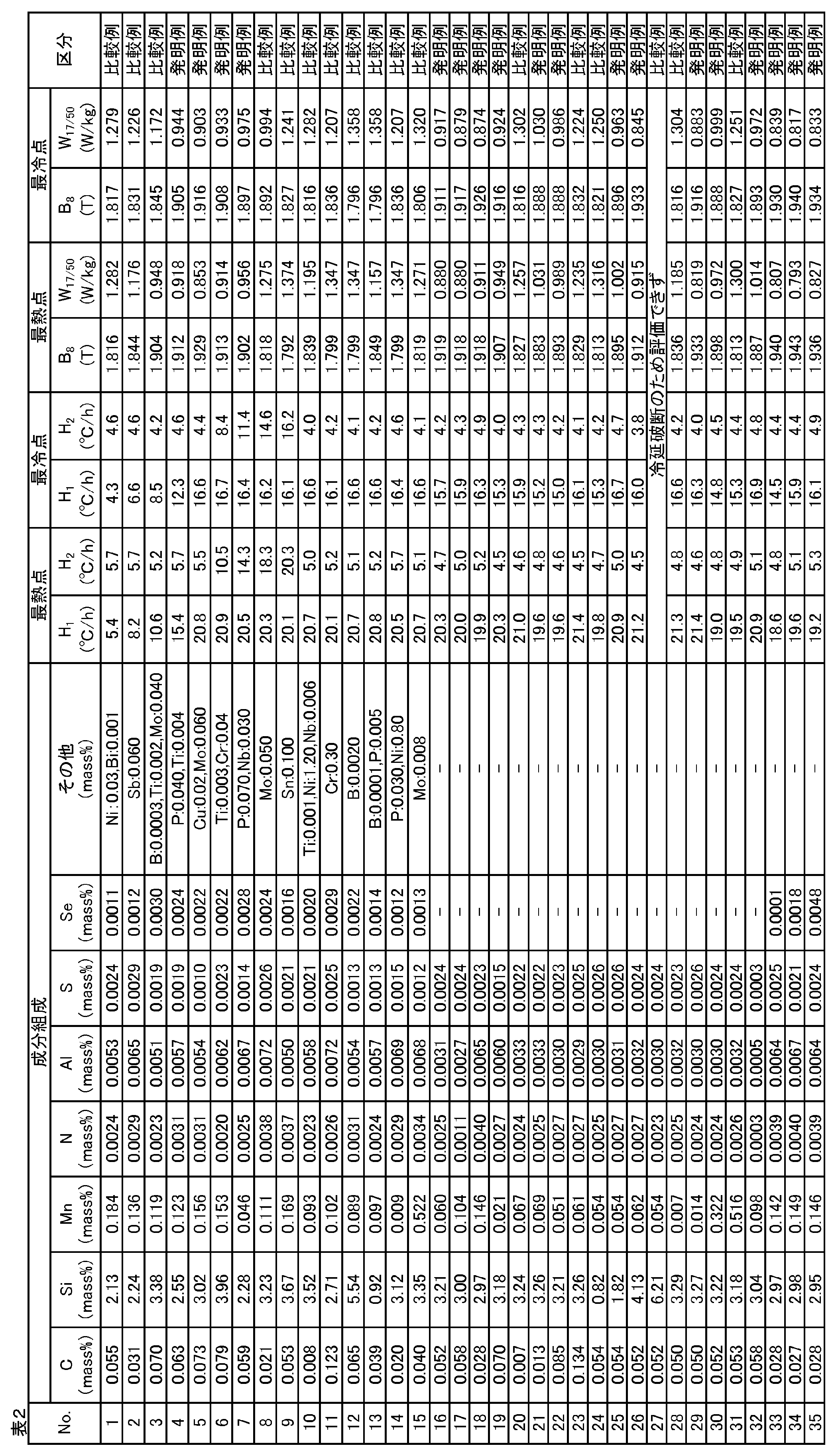
- Example 1 A steel slab having the composition shown in Table 2 was heated to 1280°C. The steel slab was then hot-rolled to obtain a hot-rolled sheet having a thickness of 2.4 mm. The hot-rolled sheet was then cold-rolled to obtain a cold-rolled sheet having a thickness of 0.23 mm. The cold-rolled sheet was then decarburized under the conditions of an H2 + N2 atmosphere, an oxidizing ( PH2O / PH2 ) of 0.3, an annealing temperature of 840°C, and a holding time at the annealing temperature of 120 seconds to obtain a decarburized annealed sheet.
- An annealing separator containing 5.0 parts by mass of TiO2 and 100 parts by mass of MgO was then applied to the surface of the decarburized annealed sheet, and the decarburized annealed sheet was then wound up to obtain a coil having a sheet width of 1200 mm and a thickness of 500 mm.
- the coil was subjected to finish annealing.
- the heating rate H 1 from room temperature to 850 ° C. and the heating rate H 2 from 850 ° C. to 950 ° C. at the hottest point and coldest point of the coil were set to the values shown in Table 2.
- the heating rate H 3 from 1000 ° C. to 1100 ° C. was 20.0 ° C. / h at the hottest point of the coil, and at this time, it was in the range of 12 ° C. / h to 18 ° C. / h at the coldest point of the coil.
- the coil was heated, and finish annealing was performed under the condition that the hottest point reached 1200 ° C. and was held for 10 hours.
- the atmosphere in the finish annealing was an inert gas atmosphere at 950 ° C. or less, and an H 2 + N 2 mixed atmosphere at 950 ° C. or more.
- the positions of the hottest point and the coldest point of the coil are uniquely determined by heat transfer calculation from the furnace structure and coil shape, etc. Therefore, the heating rates H 1 , H 2 and H 3 at the hottest and coldest points of the coil were actually measured by wrapping thermocouples at each position.
- test pieces were taken from the hottest and coldest points of the coil, and the magnetic properties (magnetic flux density B8 and iron loss W17/50 ) of each test piece were evaluated.
- the magnetic flux density B8 and iron loss W17/50 were measured according to JIS C 2550. The measurement results are shown in Table 2.
- Example 2 A steel slab having a composition containing, in mass%, C: 0.040%, Si: 3.20%, Mn: 0.070%, N: 0.0030%, Al: 0.0060%, and S: 0.0030%, with the balance being Fe and unavoidable impurities, was heated to 1280°C.
- the steel slab was hot-rolled to obtain a hot-rolled sheet having a thickness of 2.6 mm. Then, the hot-rolled sheet was cold-rolled to obtain a cold-rolled sheet having a thickness of 0.27 mm. Next, the cold-rolled sheet was decarburized under the conditions of an H 2 +N 2 atmosphere, an oxidizing (PH 2 O/PH 2 ) of 0.32, an annealing temperature of 840° C., and a holding time at the annealing temperature of 120 seconds to obtain a decarburized annealed sheet.
- PH 2 O/PH 2 oxidizing
- an annealing separator containing 2.5 parts by mass of TiO 2 and 100 parts by mass of MgO was applied to the surface of the decarburized annealed sheet, and then the decarburized annealed sheet was wound up to obtain a coil having a sheet width of 1150 mm and a thickness shown in Table 3.
- the coil was subjected to finish annealing.
- the heating rate H 1 from room temperature to 850 ° C. was 20.0 ° C. / h at the hottest point of the coil, and at this time, it was in the range of 12 ° C. / h to 18 ° C. / h at the coldest point of the coil.
- the heating rate H 2 from 850 ° C. to 950 ° C. was 5.0 ° C. / h at the hottest point of the coil, and at this time, it was in the range of 4 ° C. / h to 13 ° C. / h at the coldest point of the coil.
- the heating rate H 3 from 1000 ° C. to 1100 ° C. was set to the value shown in Table 3. Further, the coil was heated, and after the hottest point reached 1200 ° C., finish annealing was performed under the condition that it was held for 10 hours.
- the atmosphere in the finish annealing was an inert gas atmosphere at 950 ° C. or less, and an H 2 + N 2 mixed atmosphere at 950 ° C. or more.
- the positions of the hottest and coldest points of the coil are uniquely determined by heat transfer calculations based on the furnace structure, coil shape, etc. Therefore, a prediction model was created in advance and used to calculate the heating rates H 1 , H 2 , and H 3 at the hottest and coldest points of the coil.
- test pieces were taken from the hottest and coldest points of the coil, and the coating characteristics (uniformity and adhesion) of each test piece were evaluated. Uniformity was evaluated by visually observing the appearance of the coating, with a rating of "excellent” if it was uniform, “fair” if it was slightly uneven, and “poor” if it was uneven. Adhesion was also evaluated by wrapping the test pieces around round bars of various diameters and measuring the smallest diameter at which the coating did not peel off (bending peeling diameter). The evaluation results are shown in Table 3.
- Example 2 is an example of the invention in which the heating rates H1 and H2 fall within the ranges of the present invention, so the magnetic flux density B8 at the hottest point was in the range of 1.88 to 1.95 T and the iron loss W17 /50 was in the range of 0.79 to 1.05 W/kg, both of which were good values.
- the magnetic flux density B8 at the coldest spot was in the range of 1.88 to 1.94 T and the iron loss W17 /50 was in the range of 0.81 to 1.03 W/kg, both of which were good values.
Landscapes
- Chemical & Material Sciences (AREA)
- Engineering & Computer Science (AREA)
- Mechanical Engineering (AREA)
- Organic Chemistry (AREA)
- Metallurgy (AREA)
- Materials Engineering (AREA)
- Physics & Mathematics (AREA)
- Thermal Sciences (AREA)
- Crystallography & Structural Chemistry (AREA)
- Electromagnetism (AREA)
- Manufacturing & Machinery (AREA)
- Power Engineering (AREA)
- Dispersion Chemistry (AREA)
- Manufacturing Of Steel Electrode Plates (AREA)
Abstract
Description
[1]質量%で、C:0.010~0.100%、Si:1.00~5.00%、Mn:0.010~0.500%、N:0.0050%未満、Al:0.0100%未満、及びS:0.0050%未満を含有し、残部がFe及び不可避的不純物からなる成分組成を有する鋼スラブを加熱した後、熱間圧延して、熱延板を得る工程と、
前記熱延板に、1回又は中間焼鈍を挟む2回以上の冷間圧延を施して、冷延板を得る工程と、
前記冷延板に脱炭焼鈍を施して、脱炭焼鈍板を得る工程と、
前記脱炭焼鈍板に焼鈍分離剤を塗布した後、前記脱炭焼鈍板を巻き取って、コイルを得る工程と、
前記コイルに対して仕上げ焼鈍を施す工程と、
を有し、
前記仕上げ焼鈍において、前記コイルの最熱点及び最冷点の両方で、室温から850℃までの加熱速度H1が10.0℃/h以上であり、かつ、850℃から950℃までの加熱速度H2が15.0℃/h以下であることを特徴とする、方向性電磁鋼板の製造方法。
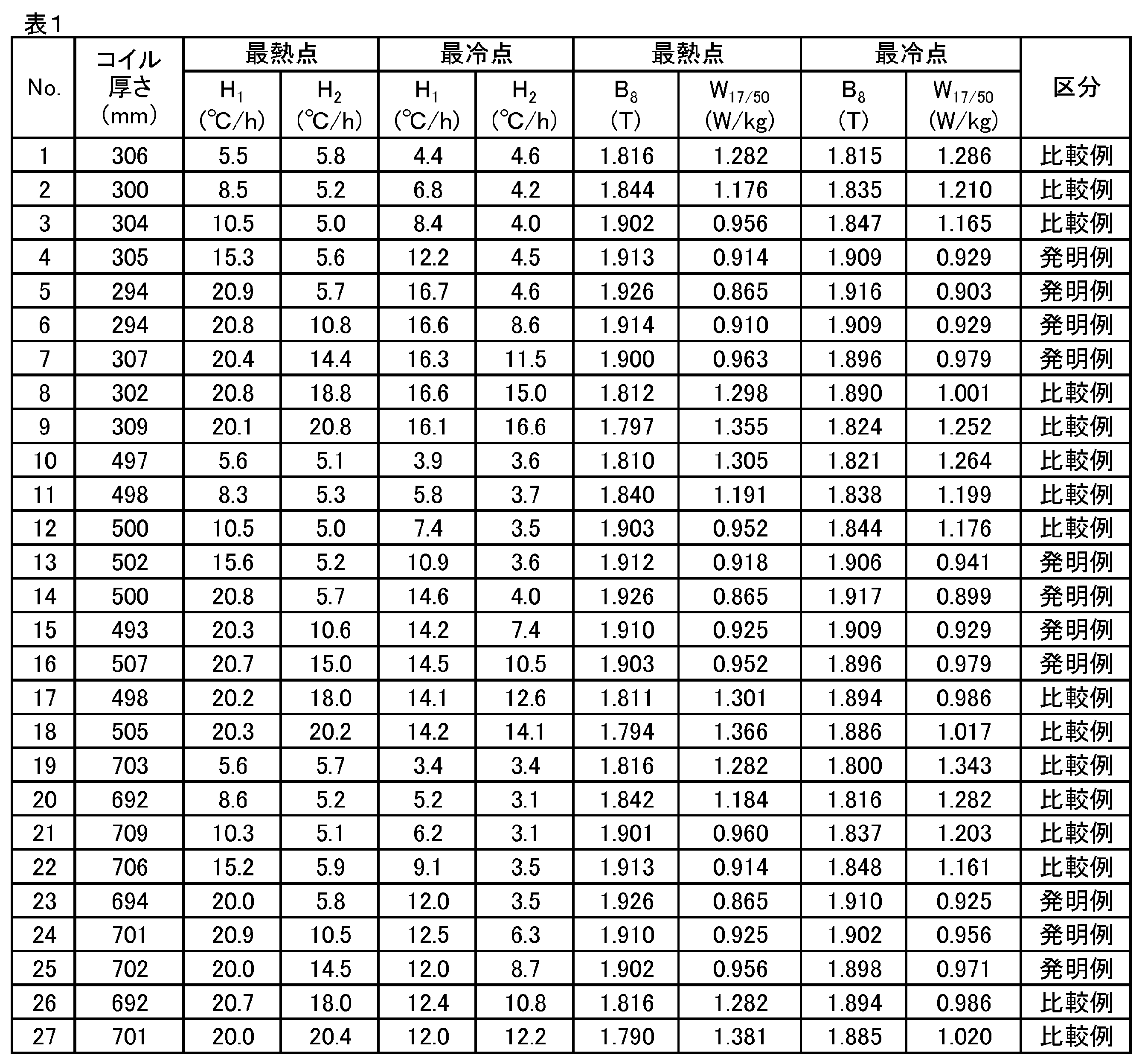
表2に示す成分組成を有する鋼スラブを1280℃に加熱した。次いで、鋼スラブに熱間圧延を施して、板厚2.4mmの熱延板を得た。その後、熱延板に冷間圧延を施して、板厚0.23mmの冷延板を得た。次いで、冷延板に、H2+N2雰囲気、酸化性(PH2O/PH2)が0.3、焼鈍温度が840℃、焼鈍温度での保持時間が120秒間の条件で脱炭焼鈍を施して、脱炭焼鈍板を得た。次いで、脱炭焼鈍板の表面に、MgO:100質量部に対してTiO2:5.0質量部を添加した焼鈍分離剤を塗布した後、脱炭焼鈍板を巻き取って、板幅が1200mmで厚さが500mmのコイルを得た。
質量%で、C:0.040%、Si:3.20%、Mn:0.070%、N:0.0030%、Al:0.0060%、及びS:0.0030%を含有し、残部がFe及び不可避的不純物からなる成分組成を有する鋼スラブを1280℃に加熱した。

Claims (3)
- 質量%で、C:0.010~0.100%、Si:1.00~5.00%、Mn:0.010~0.500%、N:0.0050%未満、Al:0.0100%未満、及びS:0.0050%未満を含有し、残部がFe及び不可避的不純物からなる成分組成を有する鋼スラブを加熱した後、熱間圧延して、熱延板を得る工程と、
前記熱延板に、1回又は中間焼鈍を挟む2回以上の冷間圧延を施して、冷延板を得る工程と、
前記冷延板に脱炭焼鈍を施して、脱炭焼鈍板を得る工程と、
前記脱炭焼鈍板に焼鈍分離剤を塗布した後、前記脱炭焼鈍板を巻き取って、コイルを得る工程と、
前記コイルに対して仕上げ焼鈍を施す工程と、
を有し、
前記仕上げ焼鈍において、前記コイルの最熱点及び最冷点の両方で、室温から850℃までの加熱速度H1が10.0℃/h以上であり、かつ、850℃から950℃までの加熱速度H2が15.0℃/h以下であることを特徴とする、方向性電磁鋼板の製造方法。 - 前記仕上げ焼鈍において、前記コイルの最熱点及び最冷点の両方で、1000℃から1100℃までの加熱速度H3が5.0℃/h以上30.0℃/h以下である、請求項1に記載の方向性電磁鋼板の製造方法。
- 前記成分組成が、さらに、質量%で、Se:0.0001~0.0050%、B:0.0001~0.0050%、P:0.005~0.100%、Ti:0.001~0.010%、Cr:0.01~0.50%、Ni:0.01~1.50%、Cu:0.01~0.50%、Nb:0.001~0.100%、Mo:0.005~0.100%、Sn:0.005~0.500%、Sb:0.005~0.500%、及びBi:0.001~0.050%からなる群から選択される一種以上を含む、請求項1又は2に記載の方向性電磁鋼板の製造方法。
Priority Applications (4)
| Application Number | Priority Date | Filing Date | Title |
|---|---|---|---|
| JP2024531415A JPWO2024162447A1 (ja) | 2023-02-01 | 2024-02-01 | |
| CN202480007848.9A CN120584204A (zh) | 2023-02-01 | 2024-02-01 | 取向性电磁钢板的制造方法 |
| KR1020257026208A KR20250132559A (ko) | 2023-02-01 | 2024-02-01 | 방향성 전자 강판의 제조 방법 |
| EP24750396.4A EP4621080A4 (en) | 2023-02-01 | 2024-02-01 | METHOD FOR PRODUCING A CORN-ORIENTED ELECTRIC STEEL SHEET |
Applications Claiming Priority (2)
| Application Number | Priority Date | Filing Date | Title |
|---|---|---|---|
| JP2023-014257 | 2023-02-01 | ||
| JP2023014257 | 2023-02-01 |
Publications (1)
| Publication Number | Publication Date |
|---|---|
| WO2024162447A1 true WO2024162447A1 (ja) | 2024-08-08 |
Family
ID=92146869
Family Applications (1)
| Application Number | Title | Priority Date | Filing Date |
|---|---|---|---|
| PCT/JP2024/003357 Ceased WO2024162447A1 (ja) | 2023-02-01 | 2024-02-01 | 方向性電磁鋼板の製造方法 |
Country Status (5)
| Country | Link |
|---|---|
| EP (1) | EP4621080A4 (ja) |
| JP (1) | JPWO2024162447A1 (ja) |
| KR (1) | KR20250132559A (ja) |
| CN (1) | CN120584204A (ja) |
| WO (1) | WO2024162447A1 (ja) |
Citations (3)
| Publication number | Priority date | Publication date | Assignee | Title |
|---|---|---|---|---|
| JP2006274405A (ja) * | 2005-03-30 | 2006-10-12 | Jfe Steel Kk | 高磁束密度方向性電磁鋼板の製造方法 |
| WO2016067636A1 (ja) * | 2014-10-30 | 2016-05-06 | Jfeスチール株式会社 | 方向性電磁鋼板の製造方法 |
| WO2022186357A1 (ja) * | 2021-03-03 | 2022-09-09 | Jfeスチール株式会社 | 方向性電磁鋼板の仕上げ焼鈍条件の決定方法およびその決定方法を用いた方向性電磁鋼板の製造方法 |
Family Cites Families (11)
| Publication number | Priority date | Publication date | Assignee | Title |
|---|---|---|---|---|
| JPS5113469B2 (ja) | 1972-10-13 | 1976-04-28 | ||
| AT329358B (de) | 1974-06-04 | 1976-05-10 | Voest Ag | Schwingmuhle zum zerkleinern von mahlgut |
| BR9800978A (pt) * | 1997-03-26 | 2000-05-16 | Kawasaki Steel Co | Chapas elétricas de aço com grão orientado tendo perda de ferro muito baixa e o processo de produção da mesma |
| JP3707268B2 (ja) | 1998-10-28 | 2005-10-19 | Jfeスチール株式会社 | 方向性電磁鋼板の製造方法 |
| JP5862873B2 (ja) * | 2011-12-27 | 2016-02-16 | Jfeスチール株式会社 | 方向性電磁鋼板の製造方法 |
| JP6344263B2 (ja) | 2015-02-25 | 2018-06-20 | Jfeスチール株式会社 | 方向性電磁鋼板の製造方法 |
| CN108699621B (zh) * | 2016-03-09 | 2020-06-26 | 杰富意钢铁株式会社 | 取向性电磁钢板的制造方法 |
| JP6572956B2 (ja) * | 2016-10-19 | 2019-09-11 | Jfeスチール株式会社 | 方向性電磁鋼板の製造方法 |
| JP6866901B2 (ja) | 2018-03-30 | 2021-04-28 | Jfeスチール株式会社 | 方向性電磁鋼板の製造方法 |
| WO2020145319A1 (ja) * | 2019-01-08 | 2020-07-16 | 日本製鉄株式会社 | 方向性電磁鋼板の製造方法および方向性電磁鋼板 |
| WO2022250162A1 (ja) * | 2021-05-28 | 2022-12-01 | Jfeスチール株式会社 | 方向性電磁鋼板の製造方法 |
-
2024
- 2024-02-01 JP JP2024531415A patent/JPWO2024162447A1/ja active Pending
- 2024-02-01 EP EP24750396.4A patent/EP4621080A4/en active Pending
- 2024-02-01 CN CN202480007848.9A patent/CN120584204A/zh active Pending
- 2024-02-01 WO PCT/JP2024/003357 patent/WO2024162447A1/ja not_active Ceased
- 2024-02-01 KR KR1020257026208A patent/KR20250132559A/ko active Pending
Patent Citations (3)
| Publication number | Priority date | Publication date | Assignee | Title |
|---|---|---|---|---|
| JP2006274405A (ja) * | 2005-03-30 | 2006-10-12 | Jfe Steel Kk | 高磁束密度方向性電磁鋼板の製造方法 |
| WO2016067636A1 (ja) * | 2014-10-30 | 2016-05-06 | Jfeスチール株式会社 | 方向性電磁鋼板の製造方法 |
| WO2022186357A1 (ja) * | 2021-03-03 | 2022-09-09 | Jfeスチール株式会社 | 方向性電磁鋼板の仕上げ焼鈍条件の決定方法およびその決定方法を用いた方向性電磁鋼板の製造方法 |
Non-Patent Citations (1)
| Title |
|---|
| See also references of EP4621080A1 * |
Also Published As
| Publication number | Publication date |
|---|---|
| EP4621080A4 (en) | 2026-03-04 |
| EP4621080A1 (en) | 2025-09-24 |
| CN120584204A (zh) | 2025-09-02 |
| JPWO2024162447A1 (ja) | 2024-08-08 |
| KR20250132559A (ko) | 2025-09-04 |
Similar Documents
| Publication | Publication Date | Title |
|---|---|---|
| JP5854233B2 (ja) | 方向性電磁鋼板の製造方法 | |
| JP5988026B2 (ja) | 方向性電磁鋼板の製造方法 | |
| JP6844125B2 (ja) | 方向性電磁鋼板の製造方法 | |
| KR101683693B1 (ko) | 방향성 전자 강판의 제조 방법 | |
| JP6132103B2 (ja) | 方向性電磁鋼板の製造方法 | |
| CN113825847B (zh) | 取向性电磁钢板的制造方法 | |
| JP2012126989A (ja) | 方向性電磁鋼板の製造方法 | |
| JP7197068B1 (ja) | 方向性電磁鋼板の製造方法 | |
| JP6137490B2 (ja) | 一次再結晶集合組織の予測方法および方向性電磁鋼板の製造方法 | |
| JP5920387B2 (ja) | 方向性電磁鋼板の製造方法 | |
| JP7623636B2 (ja) | 方向性電磁鋼板の製造方法 | |
| JP5712652B2 (ja) | 方向性電磁鋼板の製造方法 | |
| WO2024162447A1 (ja) | 方向性電磁鋼板の製造方法 | |
| WO2022210503A1 (ja) | 方向性電磁鋼板の製造方法 | |
| JP2017110304A (ja) | 方向性電磁鋼板の製造方法 | |
| JP7816665B1 (ja) | 方向性電磁鋼板の製造方法 | |
| JP7816664B1 (ja) | 方向性電磁鋼板の製造方法 | |
| JP7831718B1 (ja) | 方向性電磁鋼板の製造方法 | |
| JP2000038616A (ja) | 側歪の少ない方向性けい素鋼板の製造方法 | |
| JP7338511B2 (ja) | 方向性電磁鋼板の製造方法 | |
| WO2025243810A1 (ja) | 方向性電磁鋼板の製造方法 | |
| WO2024111567A1 (ja) | 脱炭焼鈍後の酸素目付量予測モデルとその作成方法ならびに方向性電磁鋼板の製造方法 | |
| WO2026048322A1 (ja) | 方向性電磁鋼板の製造方法 | |
| JP2024546161A (ja) | 方向性電磁鋼板およびその製造方法 | |
| CN118632943A (zh) | 用于产生含铬高磁导率晶粒取向电工钢的改进方法 |
Legal Events
| Date | Code | Title | Description |
|---|---|---|---|
| WWE | Wipo information: entry into national phase |
Ref document number: 2024531415 Country of ref document: JP |
|
| 121 | Ep: the epo has been informed by wipo that ep was designated in this application |
Ref document number: 24750396 Country of ref document: EP Kind code of ref document: A1 |
|
| WWE | Wipo information: entry into national phase |
Ref document number: 202517054109 Country of ref document: IN |
|
| WWE | Wipo information: entry into national phase |
Ref document number: 2024750396 Country of ref document: EP |
|
| ENP | Entry into the national phase |
Ref document number: 2024750396 Country of ref document: EP Effective date: 20250619 |
|
| WWE | Wipo information: entry into national phase |
Ref document number: 202480007848.9 Country of ref document: CN |
|
| ENP | Entry into the national phase |
Ref document number: 1020257026208 Country of ref document: KR Free format text: ST27 STATUS EVENT CODE: A-0-1-A10-A15-NAP-PA0105 (AS PROVIDED BY THE NATIONAL OFFICE) |
|
| WWE | Wipo information: entry into national phase |
Ref document number: 1020257026208 Country of ref document: KR |
|
| NENP | Non-entry into the national phase |
Ref country code: DE |
|
| WWP | Wipo information: published in national office |
Ref document number: 202480007848.9 Country of ref document: CN |
|
| WWP | Wipo information: published in national office |
Ref document number: 202517054109 Country of ref document: IN |
|
| WWP | Wipo information: published in national office |
Ref document number: 2024750396 Country of ref document: EP |