WO2024166457A1 - アンモニアガス供給システム及び内燃機関システム - Google Patents
アンモニアガス供給システム及び内燃機関システム Download PDFInfo
- Publication number
- WO2024166457A1 WO2024166457A1 PCT/JP2023/039078 JP2023039078W WO2024166457A1 WO 2024166457 A1 WO2024166457 A1 WO 2024166457A1 JP 2023039078 W JP2023039078 W JP 2023039078W WO 2024166457 A1 WO2024166457 A1 WO 2024166457A1
- Authority
- WO
- WIPO (PCT)
- Prior art keywords
- coolant
- temperature
- ammonia
- heat medium
- exhaust gas
- Prior art date
- Legal status (The legal status is an assumption and is not a legal conclusion. Google has not performed a legal analysis and makes no representation as to the accuracy of the status listed.)
- Ceased
Links
Images



Classifications
-
- F—MECHANICAL ENGINEERING; LIGHTING; HEATING; WEAPONS; BLASTING
- F01—MACHINES OR ENGINES IN GENERAL; ENGINE PLANTS IN GENERAL; STEAM ENGINES
- F01N—GAS-FLOW SILENCERS OR EXHAUST APPARATUS FOR MACHINES OR ENGINES IN GENERAL; GAS-FLOW SILENCERS OR EXHAUST APPARATUS FOR INTERNAL-COMBUSTION ENGINES
- F01N3/00—Exhaust or silencing apparatus having means for purifying, rendering innocuous, or otherwise treating exhaust
- F01N3/08—Exhaust or silencing apparatus having means for purifying, rendering innocuous, or otherwise treating exhaust for rendering innocuous
- F01N3/10—Exhaust or silencing apparatus having means for purifying, rendering innocuous, or otherwise treating exhaust for rendering innocuous by thermal or catalytic conversion of noxious components of exhaust
- F01N3/18—Exhaust or silencing apparatus having means for purifying, rendering innocuous, or otherwise treating exhaust for rendering innocuous by thermal or catalytic conversion of noxious components of exhaust characterised by methods of operation; Control
- F01N3/20—Exhaust or silencing apparatus having means for purifying, rendering innocuous, or otherwise treating exhaust for rendering innocuous by thermal or catalytic conversion of noxious components of exhaust characterised by methods of operation; Control specially adapted for catalytic conversion
- F01N3/206—Adding periodically or continuously substances to exhaust gases for promoting purification, e.g. catalytic material in liquid form, NOx reducing agents
- F01N3/2066—Selective catalytic reduction [SCR]
-
- F—MECHANICAL ENGINEERING; LIGHTING; HEATING; WEAPONS; BLASTING
- F02—COMBUSTION ENGINES; HOT-GAS OR COMBUSTION-PRODUCT ENGINE PLANTS
- F02D—CONTROLLING COMBUSTION ENGINES
- F02D19/00—Controlling engines characterised by their use of non-liquid fuels, pluralities of fuels, or non-fuel substances added to the combustible mixtures
- F02D19/02—Controlling engines characterised by their use of non-liquid fuels, pluralities of fuels, or non-fuel substances added to the combustible mixtures peculiar to engines working with gaseous fuels
-
- F—MECHANICAL ENGINEERING; LIGHTING; HEATING; WEAPONS; BLASTING
- F02—COMBUSTION ENGINES; HOT-GAS OR COMBUSTION-PRODUCT ENGINE PLANTS
- F02D—CONTROLLING COMBUSTION ENGINES
- F02D19/00—Controlling engines characterised by their use of non-liquid fuels, pluralities of fuels, or non-fuel substances added to the combustible mixtures
- F02D19/02—Controlling engines characterised by their use of non-liquid fuels, pluralities of fuels, or non-fuel substances added to the combustible mixtures peculiar to engines working with gaseous fuels
- F02D19/021—Control of components of the fuel supply system
- F02D19/022—Control of components of the fuel supply system to adjust the fuel pressure, temperature or composition
-
- F—MECHANICAL ENGINEERING; LIGHTING; HEATING; WEAPONS; BLASTING
- F02—COMBUSTION ENGINES; HOT-GAS OR COMBUSTION-PRODUCT ENGINE PLANTS
- F02D—CONTROLLING COMBUSTION ENGINES
- F02D19/00—Controlling engines characterised by their use of non-liquid fuels, pluralities of fuels, or non-fuel substances added to the combustible mixtures
- F02D19/06—Controlling engines characterised by their use of non-liquid fuels, pluralities of fuels, or non-fuel substances added to the combustible mixtures peculiar to engines working with pluralities of fuels, e.g. alternatively with light and heavy fuel oil, other than engines indifferent to the fuel consumed
- F02D19/0639—Controlling engines characterised by their use of non-liquid fuels, pluralities of fuels, or non-fuel substances added to the combustible mixtures peculiar to engines working with pluralities of fuels, e.g. alternatively with light and heavy fuel oil, other than engines indifferent to the fuel consumed characterised by the type of fuels
- F02D19/0642—Controlling engines characterised by their use of non-liquid fuels, pluralities of fuels, or non-fuel substances added to the combustible mixtures peculiar to engines working with pluralities of fuels, e.g. alternatively with light and heavy fuel oil, other than engines indifferent to the fuel consumed characterised by the type of fuels at least one fuel being gaseous, the other fuels being gaseous or liquid at standard conditions
- F02D19/0644—Controlling engines characterised by their use of non-liquid fuels, pluralities of fuels, or non-fuel substances added to the combustible mixtures peculiar to engines working with pluralities of fuels, e.g. alternatively with light and heavy fuel oil, other than engines indifferent to the fuel consumed characterised by the type of fuels at least one fuel being gaseous, the other fuels being gaseous or liquid at standard conditions the gaseous fuel being hydrogen, ammonia or carbon monoxide
-
- F—MECHANICAL ENGINEERING; LIGHTING; HEATING; WEAPONS; BLASTING
- F02—COMBUSTION ENGINES; HOT-GAS OR COMBUSTION-PRODUCT ENGINE PLANTS
- F02D—CONTROLLING COMBUSTION ENGINES
- F02D19/00—Controlling engines characterised by their use of non-liquid fuels, pluralities of fuels, or non-fuel substances added to the combustible mixtures
- F02D19/06—Controlling engines characterised by their use of non-liquid fuels, pluralities of fuels, or non-fuel substances added to the combustible mixtures peculiar to engines working with pluralities of fuels, e.g. alternatively with light and heavy fuel oil, other than engines indifferent to the fuel consumed
- F02D19/0663—Details on the fuel supply system, e.g. tanks, valves, pipes, pumps, rails, injectors or mixers
- F02D19/0668—Treating or cleaning means; Fuel filters
- F02D19/0671—Means to generate or modify a fuel, e.g. reformers, electrolytic cells or membranes
-
- F—MECHANICAL ENGINEERING; LIGHTING; HEATING; WEAPONS; BLASTING
- F02—COMBUSTION ENGINES; HOT-GAS OR COMBUSTION-PRODUCT ENGINE PLANTS
- F02M—SUPPLYING COMBUSTION ENGINES IN GENERAL WITH COMBUSTIBLE MIXTURES OR CONSTITUENTS THEREOF
- F02M21/00—Apparatus for supplying engines with non-liquid fuels, e.g. gaseous fuels stored in liquid form
- F02M21/02—Apparatus for supplying engines with non-liquid fuels, e.g. gaseous fuels stored in liquid form for gaseous fuels
- F02M21/0203—Apparatus for supplying engines with non-liquid fuels, e.g. gaseous fuels stored in liquid form for gaseous fuels characterised by the type of gaseous fuel
- F02M21/0206—Non-hydrocarbon fuels, e.g. hydrogen, ammonia or carbon monoxide
-
- F—MECHANICAL ENGINEERING; LIGHTING; HEATING; WEAPONS; BLASTING
- F02—COMBUSTION ENGINES; HOT-GAS OR COMBUSTION-PRODUCT ENGINE PLANTS
- F02M—SUPPLYING COMBUSTION ENGINES IN GENERAL WITH COMBUSTIBLE MIXTURES OR CONSTITUENTS THEREOF
- F02M21/00—Apparatus for supplying engines with non-liquid fuels, e.g. gaseous fuels stored in liquid form
- F02M21/02—Apparatus for supplying engines with non-liquid fuels, e.g. gaseous fuels stored in liquid form for gaseous fuels
- F02M21/06—Apparatus for de-liquefying, e.g. by heating
-
- F—MECHANICAL ENGINEERING; LIGHTING; HEATING; WEAPONS; BLASTING
- F01—MACHINES OR ENGINES IN GENERAL; ENGINE PLANTS IN GENERAL; STEAM ENGINES
- F01N—GAS-FLOW SILENCERS OR EXHAUST APPARATUS FOR MACHINES OR ENGINES IN GENERAL; GAS-FLOW SILENCERS OR EXHAUST APPARATUS FOR INTERNAL-COMBUSTION ENGINES
- F01N2610/00—Adding substances to exhaust gases
- F01N2610/02—Adding substances to exhaust gases the substance being ammonia or urea
-
- F—MECHANICAL ENGINEERING; LIGHTING; HEATING; WEAPONS; BLASTING
- F01—MACHINES OR ENGINES IN GENERAL; ENGINE PLANTS IN GENERAL; STEAM ENGINES
- F01N—GAS-FLOW SILENCERS OR EXHAUST APPARATUS FOR MACHINES OR ENGINES IN GENERAL; GAS-FLOW SILENCERS OR EXHAUST APPARATUS FOR INTERNAL-COMBUSTION ENGINES
- F01N2610/00—Adding substances to exhaust gases
- F01N2610/10—Adding substances to exhaust gases the substance being heated, e.g. by heating tank or supply line of the added substance
-
- F—MECHANICAL ENGINEERING; LIGHTING; HEATING; WEAPONS; BLASTING
- F01—MACHINES OR ENGINES IN GENERAL; ENGINE PLANTS IN GENERAL; STEAM ENGINES
- F01N—GAS-FLOW SILENCERS OR EXHAUST APPARATUS FOR MACHINES OR ENGINES IN GENERAL; GAS-FLOW SILENCERS OR EXHAUST APPARATUS FOR INTERNAL-COMBUSTION ENGINES
- F01N2610/00—Adding substances to exhaust gases
- F01N2610/14—Arrangements for the supply of substances, e.g. conduits
- F01N2610/1406—Storage means for substances, e.g. tanks or reservoirs
-
- Y—GENERAL TAGGING OF NEW TECHNOLOGICAL DEVELOPMENTS; GENERAL TAGGING OF CROSS-SECTIONAL TECHNOLOGIES SPANNING OVER SEVERAL SECTIONS OF THE IPC; TECHNICAL SUBJECTS COVERED BY FORMER USPC CROSS-REFERENCE ART COLLECTIONS [XRACs] AND DIGESTS
- Y02—TECHNOLOGIES OR APPLICATIONS FOR MITIGATION OR ADAPTATION AGAINST CLIMATE CHANGE
- Y02T—CLIMATE CHANGE MITIGATION TECHNOLOGIES RELATED TO TRANSPORTATION
- Y02T10/00—Road transport of goods or passengers
- Y02T10/10—Internal combustion engine [ICE] based vehicles
- Y02T10/12—Improving ICE efficiencies
-
- Y—GENERAL TAGGING OF NEW TECHNOLOGICAL DEVELOPMENTS; GENERAL TAGGING OF CROSS-SECTIONAL TECHNOLOGIES SPANNING OVER SEVERAL SECTIONS OF THE IPC; TECHNICAL SUBJECTS COVERED BY FORMER USPC CROSS-REFERENCE ART COLLECTIONS [XRACs] AND DIGESTS
- Y02—TECHNOLOGIES OR APPLICATIONS FOR MITIGATION OR ADAPTATION AGAINST CLIMATE CHANGE
- Y02T—CLIMATE CHANGE MITIGATION TECHNOLOGIES RELATED TO TRANSPORTATION
- Y02T10/00—Road transport of goods or passengers
- Y02T10/10—Internal combustion engine [ICE] based vehicles
- Y02T10/30—Use of alternative fuels, e.g. biofuels
Definitions
- the present disclosure relates to an ammonia gas supply system for supplying ammonia gas to an internal combustion engine, and an internal combustion engine system including the ammonia gas supply system.
- Patent Document 1 discloses a fuel tank with a pump and a heat exchanger installed in the fuel piping system as devices for controlling the temperature and pressure of the liquid ammonia supplied to an engine that uses liquid ammonia as fuel.
- Ammonia is usually stored in a container in a cooled and pressurized liquid state (liquid ammonia), and when ammonia gas is used as fuel for an internal combustion engine, the liquid ammonia must be heated in some way.
- a stable supply of ammonia gas is required to stably operate an internal combustion engine that uses ammonia gas as fuel.
- the flow rate of ammonia gas required by the internal combustion engine changes according to changes in the operating state of the internal combustion engine (load and rotation speed of the internal combustion engine), so pressure and temperature management of the ammonia gas is required to keep up with this change in flow rate.
- temperature and pressure adjustments in the fuel pipes that introduce ammonia gas to the internal combustion engine may become unstable when there is a sudden increase or decrease in the amount of ammonia gas supplied to the internal combustion engine.
- At least one embodiment of the present disclosure aims to provide an ammonia gas supply system and an internal combustion engine system that can stably supply ammonia gas to an internal combustion engine even when the operating state of the internal combustion engine changes.
- an ammonia gas supply system includes: An ammonia storage tank configured to be capable of storing liquid ammonia; a tank warmer configured to warm the ammonia storage tank and vaporize the liquid ammonia stored inside the ammonia storage tank; and an ammonia gas introduction line for introducing ammonia gas generated by vaporizing the liquid ammonia inside the ammonia storage tank to an internal combustion engine.
- an internal combustion engine system includes: an internal combustion engine fueled by ammonia gas; and the ammonia gas supply system.
- At least one embodiment of the present disclosure provides an ammonia gas supply system and an internal combustion engine system that can stably supply ammonia gas to an internal combustion engine even when the operating state of the internal combustion engine changes.
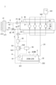
- FIG. 1 is a schematic diagram of an internal combustion engine system according to one embodiment of the present disclosure.
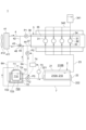
- FIG. 1 is a schematic diagram of an internal combustion engine system according to one embodiment of the present disclosure.
- FIG. 1 is a schematic diagram of an internal combustion engine system according to one embodiment of the present disclosure.
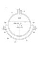
- FIG. 2 is a schematic cross-sectional view of an ammonia storage tank and tank warmer of an ammonia gas supply system according to an embodiment of the present disclosure.
- FIG. 3 is a diagram showing a modification of the ammonia gas supply system shown in FIG. 2 .
- FIG. 4 is a flow diagram showing an example of control in the ammonia gas supply system shown in FIG. 3 .
- FIG. 4 is a diagram showing a modification of the ammonia gas supply system shown in FIG.
- FIG. 1 is a schematic diagram of an internal combustion engine system 1 according to one embodiment of the present disclosure.
- an ammonia gas supply system 2 according to some embodiments is for supplying ammonia gas to an internal combustion engine 3 that uses ammonia gas as fuel, and is mounted on the internal combustion engine system 1.
- the internal combustion engine system 1 includes the ammonia gas supply system 2 and the internal combustion engine 3.
- the internal combustion engine 3 includes at least one (in the illustrated example, a plurality of) cylinders 31. Each of the plurality of cylinders 31 has a combustion chamber 32 for combusting fuel.
- the internal combustion engine 3 is configured to combust fuel (e.g., gas fuel such as ammonia gas, or liquid fuel such as diesel or gasoline) and combustion gas (e.g., air) in each combustion chamber 32 of the plurality of cylinders 31.
- fuel e.g., gas fuel such as ammonia gas, or liquid fuel such as diesel or gasoline
- combustion gas e.g., air
- the internal combustion engine 3 further includes at least one (in the illustrated example, multiple) gas fuel supply devices 33 configured to supply ammonia gas (gas fuel) to the inside of the internal combustion engine 3 (e.g., the combustion chamber 32 or the air supply pipe that supplies air to the combustion chamber 32), and at least one (in the illustrated example, multiple) liquid fuel supply devices 34 configured to supply liquid fuel to the inside of the internal combustion engine 3 (e.g., the combustion chamber 32 or the air supply pipe that supplies air to the combustion chamber 32).
- the gas fuel supply device 33 and the liquid fuel supply device 34 may be fuel injection valves configured to inject fuel.
- the internal combustion engine 3 may further include an ignition device (ignition plug) configured to ignite the mixture of fuel and air in the combustion chamber 32.
- the gas fuel supply device 33, the liquid fuel supply device 34, and the above ignition device are provided individually for each cylinder 31.
- the internal combustion engine 3 further includes a liquid fuel storage tank 341 configured to store liquid fuel, and a liquid fuel introduction line 342 for guiding the liquid fuel from the liquid fuel storage tank 341 to each of the multiple liquid fuel supply devices 34.
- the liquid fuel introduction line 342 forms a flow path for circulating the liquid fuel, and is formed by, for example, piping.
- an ammonia gas supply system 2 includes an ammonia storage tank 21, a tank heater 22, and an ammonia gas introduction line 23.
- the ammonia storage tank 21 is configured to be capable of storing liquid ammonia.
- the tank heater 22 is configured to heat the ammonia storage tank 21 and vaporize the liquid ammonia stored inside the ammonia storage tank 21.
- the ammonia gas introduction line 23 is a line (supply system) for guiding ammonia gas, which is obtained by vaporizing the liquid ammonia inside the ammonia storage tank 21, to the internal combustion engine 3.
- the ammonia storage tank 21 is configured to define an internal space 210 therein for storing liquid ammonia and ammonia gas (ammonia in a gaseous state).
- the internal space 210 includes a liquid phase section 210A in which liquid ammonia (ammonia in a liquid state) is stored, and a gas phase section 210B formed above the liquid phase section 210A in which ammonia gas is stored.
- the liquid ammonia stored in the liquid phase section 210A is vaporized into ammonia gas by external heat input via the tank heater 22.
- ammonia gas introduction line 23 One end (upstream end) of the ammonia gas introduction line 23 is connected to the ammonia storage tank 21, and the other end (downstream end) is connected to the internal combustion engine 3.
- the ammonia gas introduction line 23 forms a flow path for circulating ammonia gas, and is formed by, for example, piping.
- the flow path formed in the ammonia gas introduction line 23 communicates with the gas phase section 210B, and ammonia gas is extracted from the gas phase section 210B to the ammonia gas introduction line 23.
- the other end of the ammonia gas introduction line 23 may be branched into multiple parts, with each of the multiple downstream ends being connected to a gas fuel supply device 33.
- the ammonia gas stored in the ammonia storage tank 21 is at a higher pressure than the gas supply destination (e.g., the combustion chamber 32 or an air supply pipe that supplies air to the combustion chamber 32), and is introduced as fuel into the internal combustion engine 3 (multiple gas fuel supply devices 33) via the ammonia gas introduction line 23 due to the pressure difference.
- the gas supply destination e.g., the combustion chamber 32 or an air supply pipe that supplies air to the combustion chamber 32
- ammonia gas supply system 2 In order to stably operate the internal combustion engine 3 that uses ammonia gas as fuel, a stable supply of ammonia gas is required.
- the flow rate of ammonia gas required by the internal combustion engine 3 changes according to changes in the operating state of the internal combustion engine 3 (the load and rotation speed of the internal combustion engine 3).
- the ammonia gas supply system 2 needs to manage the pressure and temperature of the ammonia gas so that it can follow the changes in the flow rate of ammonia gas required by the internal combustion engine 3.
- the ammonia gas supply system 2 includes the above-mentioned ammonia storage tank 21, the above-mentioned tank heater 22, and the above-mentioned ammonia gas introduction line 23.
- the ammonia gas vaporized inside the ammonia storage tank 21 by the tank heater 22 can be introduced to the internal combustion engine 3 via the ammonia gas introduction line 23. Since the ammonia storage tank 21 has a large capacity for storing ammonia gas, it can steadily supply ammonia gas to the internal combustion engine 3 via the ammonia gas introduction line 23. In other words, although the flow rate of ammonia gas required by the internal combustion engine 3 may change depending on changes in the load and rotation speed of the internal combustion engine 3, the required amount of ammonia gas can be supplied from the ammonia storage tank 21 to the internal combustion engine 3.
- the tank heater 22 is configured to heat the liquid ammonia stored in the ammonia storage tank 21 by exhaust heat discharged from the internal combustion engine 3 during operation of the internal combustion engine 3.
- the tank heater 22 described above is configured to heat the liquid ammonia stored in the ammonia storage tank 21 with a coolant that recovers thermal energy generated by combustion in the internal combustion engine 3.
- the tank heater 22 described above may also be configured to heat the liquid ammonia stored in the ammonia storage tank 21 with exhaust gas generated by combustion in the internal combustion engine 3 (see Figure 5).
- FIG. 4 is a schematic cross-sectional view of the ammonia storage tank 21 and tank heater 22 of the ammonia gas supply system 2 according to one embodiment of the present disclosure.
- the ammonia storage tank 21 is formed in a cylindrical shape having a longitudinal direction along the axis LA.
- FIG. 4 shows schematic cross-sections of the ammonia storage tank 21 and tank heater 22 along a direction perpendicular to the axis LA.
- the tank heater 22 has a storage section 220 formed therein for storing a heating medium, which is a heat medium for heating the liquid ammonia stored in the ammonia storage tank 21.
- the tank heater 22 has an inlet 221 for introducing the heating medium from outside the tank heater 22 into the storage section 220, and an outlet 222 for discharging the heating medium from the storage section 220 to outside the tank heater 22.
- the heating medium is a cooling liquid that has been heated to a relatively high temperature by thermal energy generated by combustion in the internal combustion engine 3, and the cooling liquid is stored in the storage section 220 of the tank heater 22. Heat exchange is performed between the cooling liquid (heating medium) stored in the storage section 220 and the liquid ammonia stored in the ammonia storage tank 21. Specifically, the thermal energy of the cooling liquid stored in the storage section 220 is transferred to the liquid ammonia stored in the ammonia storage tank 21, and the liquid ammonia is heated.
- the tank heater 22 faces the outer surface of the ammonia storage tank 21 with a gap therebetween and includes a lower covering portion 223 that covers the lower part of the ammonia storage tank 21, and a pair of blocking portions 224, 225 that block the gap.
- the above-mentioned storage portion 220 is formed by the outer surface of the ammonia storage tank 21, the inner surface of the lower covering portion 223, and the inner surfaces of the pair of blocking portions 224, 225.
- the above-mentioned inlet 221 and outlet 222 are formed in the lower covering portion 223.
- the lower covering portion 223 may be formed in a circular arc shape whose cross section along a direction perpendicular to the axis LA is concave downward.
- one of the pair of blocking portions 224, 225, the blocking portion 224 extends horizontally from one end of the lower covering portion 223 and is connected to the outer surface of the ammonia storage tank 21.
- the other of the pair of blocking portions 224, 225, the blocking portion 225 extends horizontally from the other end of the lower covering portion 223 and is connected to the outer surface of the ammonia storage tank 21.
- the circumferential angles ⁇ 1, ⁇ 2 from the vertical downward direction centered on the axis LA of each of the one end and the other end of the lower covering portion 223 are 90 degrees or more in the cross section along a direction perpendicular to the axis LA.
- the tank heater 22 is not limited to the shape shown in FIG. 4 as long as it is capable of heating the liquid ammonia stored in the ammonia storage tank 21 by the heating medium.
- the above-mentioned ammonia gas supply system 2 further includes a coolant circulation line 4, a circulation line side pump P1, a cooling device 41, and a coolant introduction line 5, as shown in Figures 1 and 2.
- the internal combustion engine 3 is formed with a coolant flow passage 35 for circulating the coolant formed inside the internal combustion engine 3, a coolant inlet 36 for introducing the coolant from outside the internal combustion engine 3 into the coolant flow passage 35, and a coolant outlet 37 for discharging the coolant from the coolant flow passage 35 to outside the internal combustion engine 3.
- the coolant flow passage 35 may include, for example, a portion surrounding at least a part of the outer periphery of the combustion chamber 32 in order to cool the combustion chamber 32 of the multiple cylinders 31.
- the coolant circulation line 4 is a line (supply system) for circulating the coolant for cooling the internal combustion engine 3.
- the coolant circulation line 4 forms a flow path for distributing the coolant, and is formed by, for example, piping.
- One end (upstream end) of the coolant circulation line 4 is connected to the coolant outlet 37, and the other end (downstream end) is connected to the coolant inlet 36.
- the circulation line side pump P1 is provided in the coolant circulation line 4 and configured to increase the pressure of the coolant flowing through the coolant circulation line 4.
- the circulation line side pump P1 extracts the coolant from the coolant flow path 35 through the coolant outlet 37 to the coolant circulation line 4, and sends the coolant to the downstream side of the coolant circulation line 4.
- the cooling device 41 is a device for cooling the coolant provided in the coolant circulation line 4.
- the cooling device 41 includes a radiator 411 provided in the coolant circulation line 4 and a fan 412 for air-cooling the radiator 411.
- the coolant whose temperature has increased by recovering thermal energy generated by combustion in the internal combustion engine 3 is sent to the coolant circulation line 4 by the circulation line side pump P1 and is cooled by the cooling device 41 including the radiator 411.
- the coolant cooled by the cooling device 41 is supplied to the coolant flow path 35 via the coolant circulation line 4 and the coolant inlet 36.
- the coolant circulating in the coolant circulation line 4 may be water or an antifreeze such as glycol water.
- the coolant introduction line 5 is a line (supply system) for extracting a portion of the coolant flowing from the internal combustion engine 3 toward the cooling device 41 from the coolant circulation line 4 and guiding it to the tank heater 22.
- the coolant introduction line 5 forms a flow path for circulating the coolant, and is formed by, for example, piping.
- One end (upstream end) of the coolant introduction line 5 is connected to a connection part 44 formed between the one end of the coolant circulation line 4 and the cooling device 41, and the other end (downstream end) is connected to an inlet 221 of the tank heater 22.
- the coolant that has recovered the thermal energy generated by combustion in the internal combustion engine 3 can be introduced to the tank heater 22 via the coolant introduction line 5.
- the liquid ammonia stored in the ammonia storage tank 21 can be heated by the coolant introduced to the tank heater 22.
- the coolant circulation line 4, the circulation line side pump P1, and the cooling device 41 are the equipment that has been necessary for circulating the coolant, and by utilizing these equipment to introduce the coolant to the tank heater 22, the structure of the ammonia gas supply system 2 can be prevented from becoming complicated.
- the ammonia gas supply system 2 further includes a coolant-side pump P2 that is provided in the coolant introduction line 5 and configured to boost the pressure of the coolant flowing through the coolant introduction line 5.
- the coolant-side pump P2 extracts the coolant from the coolant circulation line 4 to the coolant introduction line 5, and sends the coolant to the downstream side (the other end side) of the coolant introduction line 5.
- the flow rate of the coolant circulating through the coolant circulation line 4 is a constant amount according to the rated capacity of the internal combustion engine 3, or varies according to the operating state of the internal combustion engine 3 (the load and rotation speed of the internal combustion engine 3).
- the coolant side pump P2 in the coolant introduction line 5 the coolant can be stably supplied to the tank heater 22 via the coolant introduction line 5 regardless of the operating state of the internal combustion engine 3.
- ammonia gas can be stably generated from liquid ammonia inside the ammonia storage tank 21.
- the above-mentioned ammonia gas supply system 2 further includes a coolant return line 6, as shown in Figs. 1 and 2.
- the coolant return line 6 is a line (supply system) for returning the coolant from the tank heater 22 to the coolant circulation line 4.
- the coolant return line 6 forms a flow path for circulating the coolant, and is formed by, for example, piping.
- the piping forming each of the coolant introduction line 5 and the coolant return line 6 may have a smaller pipe diameter than the piping forming the coolant circulation line 4.
- the coolant return line 6 has one end (upstream end) connected to the outlet 222 of the tank heater 22, and the other end (downstream end) connected to the connection 45 located between the cooling device 41 and the above-mentioned connection 44 to which the coolant introduction line 5 of the coolant circulation line 4 is connected.
- the coolant can be returned from the tank heater 22 to the coolant circulation line 4 via the coolant return line 6.
- the circulation line side pump P1, and the cooling device 41 to circulate the coolant passing through the coolant introduction line 5, the tank heater 22, and the coolant return line 6, the structure of the ammonia gas supply system 2 can be prevented from becoming complicated.
- the above-described ammonia gas supply system 2 further includes a coolant temperature acquisition device 51 and a coolant heating device 52, as shown in Fig. 2.
- the coolant temperature acquisition device 51 is configured to acquire the temperature of either the coolant present inside the tank heater 22 or the coolant flowing through the coolant introduction line 5.
- the coolant temperature acquisition device 51 may be a temperature sensor provided inside the tank heater 22, or may be a temperature sensor (see Fig. 2) provided in the coolant introduction line 5.
- the coolant heating device 52 is provided upstream of the position where the coolant temperature acquisition device 51 acquires the temperature on the coolant introduction line 5.
- the coolant heating device 52 is configured to increase the temperature of the coolant introduced into the tank heater 22 via the coolant introduction line 5 so that the temperature of the coolant acquired by the coolant temperature acquisition device 51 is equal to or higher than a predetermined value (lower limit threshold).
- the coolant heating device 52 may include, for example, an electric heater (heating device) that heats the coolant flowing through the coolant introduction line 5.
- the lower threshold is preferably 0°C or higher and 30°C or lower, and more preferably 20°C or higher and 30°C or lower.
- the coolant heating device 52 may be configured to operate when the coolant temperature acquired by the coolant temperature acquisition device 51 is lower than a predetermined value (lower threshold), and to stop operating when the coolant temperature acquired by the coolant temperature acquisition device 51 is equal to or higher than the predetermined value (lower threshold).
- the temperature of the coolant guided to the tank heater 22 may be low.
- the coolant heating device 52 ensures that the temperature of the coolant acquired by the coolant temperature acquisition device 51 is equal to or higher than a predetermined value (lower limit threshold), thereby preventing the temperature of the coolant guided to the tank heater 22 from being low. Therefore, the tank heater 22 can stably heat the liquid ammonia stored in the ammonia storage tank 21.
- the internal combustion engine 3 is configured to burn ammonia gas supplied from the gas fuel supply device 33 during normal operation when the internal combustion engine 3 is operating stably, but may be configured to burn liquid fuel supplied from the liquid fuel supply device 34 when the internal combustion engine 3 is started.
- the above-mentioned ammonia gas supply system 2 includes the above-mentioned coolant temperature acquisition device 51 and the coolant temperature reduction device 53, as shown in Fig. 2.
- the coolant temperature reduction device 53 is provided upstream of the temperature acquisition position of the coolant introduction line 5 by the coolant temperature acquisition device 51.
- the coolant temperature reduction device 53 is configured to reduce the temperature of the coolant introduced into the tank heater 22 via the coolant introduction line 5 so that the temperature of the coolant acquired by the coolant temperature acquisition device 51 becomes equal to or lower than a predetermined value (upper limit threshold).
- the coolant temperature reducing device 53 may include a radiator 531 provided in the coolant introduction line 5 and a fan 532 for cooling the radiator 531.
- the lower limit threshold is preferably 35°C or higher and 50°C or lower, and more preferably 35°C or higher and 40°C or lower.
- the temperature of the coolant introduced into the tank heater 22 is preferably about 40°C, but during normal operation of the internal combustion engine 3, the temperature of the coolant flowing through the coolant circulation line 4 from the internal combustion engine 3 to the cooling device 41 may be 80°C to 90°C.
- the coolant temperature reducing device 53 may be configured to operate when the temperature of the coolant acquired by the coolant temperature acquisition device 51 exceeds a predetermined value (upper limit threshold) and to stop operation when the temperature of the coolant acquired by the coolant temperature acquisition device 51 falls below the predetermined value (upper limit threshold).
- the temperature of the coolant guided to the tank heater 22 may become high. If the temperature of the coolant guided to the tank heater 22 becomes too high, excessive ammonia gas may be generated inside the ammonia storage tank 21, and the internal pressure of the ammonia storage tank 21 may become too high.
- the coolant temperature lowering device 53 makes the temperature of the coolant acquired by the coolant temperature acquisition device 51 equal to or lower than a predetermined value (upper limit threshold), thereby preventing the temperature of the coolant guided to the tank heater 22 from becoming too high.
- the tank heater 22 can stably heat the liquid ammonia stored in the ammonia storage tank 21.
- the coolant temperature lowering device 53 disclosed herein is applicable to the ammonia gas supply system 2 equipped with the above-mentioned coolant temperature raising device 52, and is also applicable to the ammonia gas supply system 2 not equipped with the coolant temperature raising device 52.
- the above-mentioned coolant side pump P2 is configured to have a variable output.
- the above-mentioned ammonia gas supply system 2 includes the above-mentioned coolant temperature acquisition device 51 and a control device 54.
- the control device 54 is configured to control the output of the coolant side pump P2 so that the temperature of the coolant acquired by the coolant temperature acquisition device 51 is equal to or lower than a predetermined value (upper limit threshold).
- the control device (controller) 54 is an electronic control unit for controlling the temperature of the cooling liquid guided to the tank heater 22, and may be configured as a microcomputer including a CPU (processor) (not shown), memories such as ROM and RAM, storage devices such as external storage devices, an I/O interface, and a communication interface.
- the CPU operates (e.g., performs data calculations, etc.) according to the commands of a program loaded into the main storage device of the memory, thereby realizing the various functions described below.
- the control device 54 is configured to receive the coolant temperature acquired by the coolant temperature acquisition device 51 from the coolant temperature acquisition device 51.
- the control device 54 is configured to be able to issue operation and stop instructions to the coolant side pump P2.
- the coolant side pump P2 is controlled by instructions (instruction signals) sent from the control device 54, and is configured to operate or stop in response to these instructions.
- the coolant side pump P2 is configured to change its output in accordance with output instructions sent from the control device 54.
- the control device 54 may be configured to instruct the coolant side pump P2 to output a predetermined output (first output) when the temperature of the coolant acquired by the coolant temperature acquisition device 51 falls below a predetermined value (upper threshold).
- the control device 54 may be configured to instruct the coolant side pump P2 to output a predetermined output (second output) lower than the first output when the temperature of the coolant acquired by the coolant temperature acquisition device 51 exceeds the predetermined value (upper threshold). This reduces the flow rate of the coolant guided to the tank heater (22) when the temperature of the coolant acquired by the coolant temperature acquisition device 51 exceeds the predetermined value (upper threshold).
- the output of the coolant side pump P2 is controlled to reduce the flow rate of the coolant guided to the tank heater 22, and the temperature of the coolant acquired by the coolant temperature acquisition device 51 is kept below a predetermined value (upper limit threshold), thereby preventing the temperature of the coolant guided to the tank heater 22 from becoming too high.
- a predetermined value upper limit threshold
- the control device 54 may be configured to be able to issue operation and stop instructions to the above-mentioned cooling liquid heating device 52 and cooling liquid temperature lowering device 53.
- the cooling liquid heating device 52 and cooling liquid temperature lowering device 53 may be configured to be controlled by instructions (instruction signals) sent from the control device 54 and to be driven or stopped in response to the instructions.
- the control device 54 of the present disclosure is applicable to an ammonia gas supply system 2 that includes the above-mentioned cooling liquid heating device 52 and cooling liquid temperature lowering device 53, and is also applicable to an ammonia gas supply system 2 that does not include the cooling liquid heating device 52 or cooling liquid temperature lowering device 53.
- FIG. 5 is a diagram showing a modified example of the ammonia gas supply system 2 shown in Fig. 2.
- the ammonia gas supply system 2 includes the above-mentioned ammonia storage tank 21, the above-mentioned tank heater 22, the above-mentioned ammonia gas introduction line 23, and the exhaust gas introduction line 11.
- the exhaust gas introduction line 11 is a line (supply system) for guiding the exhaust gas discharged from the internal combustion engine 3 to the tank heater 22.
- the exhaust gas introduction line 11 forms a flow path for circulating the exhaust gas, and is formed by, for example, piping.
- One end (upstream end) of the exhaust gas introduction line 11 is connected to the internal combustion engine 3, and the other end (downstream end) is connected to the inlet 221 of the tank heater 22.
- the exhaust gas discharged from the internal combustion engine 3 is guided to the tank heater 22 via the exhaust gas introduction line 11 and stored in the storage section 220.
- the exhaust gas serves as a heating medium for heating the liquid ammonia.
- the above configuration allows exhaust gas generated by combustion in the internal combustion engine 3 to be guided to the tank heater 22.
- the exhaust gas introduced into the tank heater 22 can then be used to heat the liquid ammonia stored in the ammonia storage tank 21.
- the exhaust gas introduction line 11 is a facility that has traditionally been necessary for discharging exhaust gas, and by utilizing this facility to introduce exhaust gas into the tank heater 22, the structure of the ammonia gas supply system 2 can be prevented from becoming complicated.
- the above-described ammonia gas supply system 2 further includes an exhaust gas temperature acquisition device 111 and an exhaust gas temperature reduction device 112, as shown in Fig. 5.
- the exhaust gas temperature acquisition device 111 is configured to acquire the temperature of either the exhaust gas present inside the tank heater 22 or the exhaust gas flowing through the exhaust gas introduction line 11.
- the exhaust gas temperature acquisition device 111 may be a temperature sensor provided inside the tank heater 22, or may be a temperature sensor (see Fig. 5) provided in the exhaust gas introduction line 11.
- the exhaust gas temperature reducing device 112 is provided upstream of the temperature acquisition position of the exhaust gas temperature acquisition device 111 on the exhaust gas inlet line 11.
- the exhaust gas temperature reducing device 112 is configured to reduce the temperature of the exhaust gas introduced into the tank heater 22 via the exhaust gas inlet line 11 so that the temperature of the exhaust gas acquired by the exhaust gas temperature acquisition device 111 becomes equal to or lower than a predetermined value (upper limit threshold).
- the exhaust gas cooling device 112 may include a radiator 114 provided in the exhaust gas inlet line 11 and a fan 115 for cooling the radiator 114.
- the lower threshold is preferably 35°C or higher and 50°C or lower, and more preferably 35°C or higher and 40°C or lower.
- the exhaust gas cooling device 112 may be configured to operate when the temperature of the exhaust gas acquired by the exhaust gas temperature acquisition device 111 exceeds a predetermined value (upper threshold), and to stop operation when the temperature of the exhaust gas acquired by the exhaust gas temperature acquisition device 111 falls below the predetermined value (upper threshold).
- the exhaust gas discharged from the internal combustion engine 3 has more thermal energy (exhaust heat) that can be recovered from the internal combustion engine 3 than the coolant, so the temperature of the exhaust gas guided to the tank heater 22 may become high. If the temperature of the exhaust gas guided to the tank heater 22 becomes too high, there is a risk that excessive ammonia gas will be generated inside the ammonia storage tank 21, and the internal pressure of the ammonia storage tank 21 will become too high.
- the exhaust gas temperature reduction device 112 keeps the temperature of the exhaust gas acquired by the exhaust gas temperature acquisition device 111 below a predetermined value, thereby preventing the temperature of the exhaust gas guided to the tank heater 22 from becoming too high. Therefore, the tank heater 22 can stably heat the liquid ammonia stored in the ammonia storage tank 21.
- the above-mentioned ammonia gas supply system 2 includes the above-mentioned exhaust gas temperature acquisition device 111 and an exhaust gas heating device 113, as shown in Fig. 5.
- the exhaust gas heating device 113 is provided upstream of the temperature acquisition position of the exhaust gas introduction line 11 by the exhaust gas temperature acquisition device 111.
- the exhaust gas heating device 113 is configured to increase the temperature of the exhaust gas introduced into the tank heater 22 via the exhaust gas introduction line 11 so that the temperature of the exhaust gas acquired by the exhaust gas temperature acquisition device 111 becomes equal to or higher than a predetermined value (lower limit threshold).
- the exhaust gas heating device 113 may include, for example, an electric heater (heating device) that heats the exhaust gas flowing through the exhaust gas introduction line 11.
- the lower threshold is preferably 0°C or higher and 30°C or lower, and more preferably 20°C or higher and 30°C or lower.
- the exhaust gas heating device 113 may be configured to operate when the temperature of the exhaust gas acquired by the exhaust gas temperature acquisition device 111 is lower than a predetermined value (lower threshold), and to stop operation when the temperature of the exhaust gas acquired by the exhaust gas temperature acquisition device 111 is equal to or higher than the predetermined value (lower threshold).
- the temperature of the exhaust gas guided to the tank heater 22 may be low.
- the exhaust gas heating device 113 makes the temperature of the exhaust gas acquired by the exhaust gas temperature acquisition device 111 equal to or higher than a predetermined value, thereby preventing the temperature of the exhaust gas guided to the tank heater 22 from being low, and the tank heater 22 can stably heat the liquid ammonia stored in the ammonia storage tank 21.
- the ammonia gas supply system 2 includes the exhaust gas temperature reduction device 112 and the exhaust gas temperature increase device 113, but may be configured to include either the exhaust gas temperature reduction device 112 or the exhaust gas temperature increase device 113.
- the above-mentioned ammonia gas supply system 2 may include a control device 116 configured to be able to issue operation instructions and operation stop instructions to at least one of the exhaust gas cooling device 112 and the exhaust gas heating device 113.
- the control device 116 is configured to receive the exhaust gas temperature acquired by the exhaust gas temperature acquisition device 111 from the exhaust gas temperature acquisition device 111.
- the exhaust gas cooling device 112 and the exhaust gas heating device 113 may be configured to be controlled by instructions (instruction signals) sent from the control device 116 and to be driven or stopped in response to the instructions.
- the control device 116 has a similar configuration to the control device 54 described above, although the object of temperature control is different.
- the control device (controller) 116 is an electronic control unit for controlling the temperature of the exhaust gas guided to the tank heater 22, and may be configured as a microcomputer including a CPU (processor) (not shown), memories such as ROM and RAM, storage devices such as external storage devices, an I/O interface, and a communication interface.
- the CPU operates (e.g., performs data calculations, etc.) according to the commands of a program loaded into the main storage device of the memory, for example, to realize each of the functions described below.
- the ammonia gas supply system 2 includes the above-mentioned ammonia storage tank 21, the above-mentioned tank heater 22, the above-mentioned ammonia gas introduction line 23, the heat medium circulation line 7, the heat medium side pump P3, a heat medium storage tank 71, and a heater 72.
- the heat medium circulation line 7 is a line (supply system) for circulating a heat medium (heating medium) for heating the ammonia storage tank 21.
- the heat medium circulation line 7 forms a flow path for circulating the heat medium, and is formed by, for example, piping.
- One end (downstream end) of the heat medium circulation line 7 is connected to the inlet 221 of the tank heater 22, and the other end (upstream end) is connected to the outlet 222 of the tank heater 22.
- the heat medium side pump P3 is provided in the heat medium circulation line 7 and is configured to boost the heat medium flowing through the heat medium circulation line 7.
- the heat medium side pump P3 extracts the heat medium from the tank heater 22 through the outlet 222 to the heat medium circulation line 7, and sends the heat medium to the downstream side of the heat medium circulation line 7.
- the heat medium storage tank 71 is provided in the heat medium circulation line 7 and configured to store the heat medium.
- the insulator 72 is configured to keep the heat medium stored in the heat medium storage tank 71 warm by using exhaust heat discharged from the internal combustion engine 3 when the internal combustion engine 3 is operating.
- the heat medium storage tank 71 has a storage section 710 formed therein for storing the heat medium (heating medium).
- the heat medium storage tank 71 has an inlet 711 for introducing the heat medium into the storage section 710 from the upstream side of the heat medium storage tank 71 on the heat medium circulation line 7, and an outlet 712 for discharging the heat medium from the storage section 710 to the downstream side of the heat medium storage tank 71 on the heat medium circulation line 7.
- the heat medium circulating through the heat medium circulation line 7 is preferably a liquid heat medium having a higher density than a gaseous heat medium.
- the heat medium circulating through the heat medium circulation line 7 may be an antifreeze liquid such as water or glycol water, or may be an oil such as a lubricating oil.
- the insulator 72 has a storage section 720 formed between the insulator 72 and the heat medium storage tank 71 for storing a heat medium for keeping the heat medium in the heat medium storage tank 71 warm.
- the insulator 72 includes an insulator body 723 that forms the storage section 720 between the insulator 72 and the heat medium storage tank 71, and a heat insulating material 724 that covers the outer surface of the insulator body 723.
- the insulator body 723 is formed with an inlet 721 for introducing the heat medium for heat retention from outside the insulator 72 to the storage section 720, and an outlet 722 for discharging the heat medium for heat retention from the storage section 720 to outside the insulator 72.
- the heat medium for insulation is a cooling liquid that has become relatively hot due to thermal energy generated by combustion in the internal combustion engine 3, and the cooling liquid is stored in the storage section 720 of the heat insulator 72.
- Heat exchange is performed between the cooling liquid (heat medium for insulation) stored in the storage section 720 and the heat medium stored in the heat medium storage tank 71.
- the thermal energy of the cooling liquid stored in the storage section 720 is transferred to the heat medium stored in the heat medium storage tank 71, and the heat medium is heated (kept warm). This allows the heat medium circulating through the heat medium circulation line 7 to be maintained at a temperature suitable for introduction into the tank heater 22 (for example, about 40°C).
- the heat medium stored in the heat medium storage tank 71 is kept warm by the insulator 72, thereby suppressing a drop in the temperature of the heat medium introduced into the tank heater 22 via the heat medium circulation line 7.
- the tank heater 22 can stably heat the liquid ammonia stored in the ammonia storage tank 21. Therefore, according to the above configuration, even when the internal combustion engine 3 is started, the tank heater 22 can heat the liquid ammonia to generate ammonia gas, so that the period from when the internal combustion engine 3 is started until ammonia gas can be supplied to the internal combustion engine 3 can be shortened.
- the above-mentioned ammonia gas supply system 2 further includes the above-mentioned coolant circulation line 4, the above-mentioned circulation line side pump P1, the above-mentioned cooling device 41, and a coolant introduction line 5A, as shown in FIG. 3.
- the coolant introduction line 5A is a line (supply system) for extracting a portion of the coolant flowing from the internal combustion engine 3 toward the cooling device 41 from the coolant circulation line 4 and directing it to the insulator 72.
- the coolant introduction line 5A forms a flow path for circulating the coolant, and is formed, for example, by piping.
- One end (upstream end) of the coolant introduction line 5A is connected to the connection part 44 formed between the one end of the coolant circulation line 4 and the cooling device 41, and the other end (downstream end) is connected to the inlet 721 of the insulator 72.
- the cooling liquid that recovers the thermal energy generated by the combustion in the internal combustion engine 3 can be introduced to the insulator 72 via the cooling liquid introduction line 5A.
- the heat medium stored in the heat medium storage tank 71 can be kept warm by the cooling liquid introduced into the insulator 72.
- a separate heat source for heating the liquid ammonia is not required or the separate heat source can be made smaller, so that the structure of the ammonia gas supply system 2 can be prevented from becoming complicated.
- cooling liquid circulation line 4 the circulation line side pump P1, and the cooling device 41 are conventionally necessary equipment for circulating the cooling liquid, and by using these equipment to introduce the cooling liquid into the insulator 72, the structure of the ammonia gas supply system 2 can be prevented from becoming complicated.
- the above-mentioned ammonia gas supply system 2 further includes a coolant-side pump P2 provided in the coolant introduction line 5A and configured to boost the pressure of the coolant flowing through the coolant introduction line 5A, and a coolant return line 6A.
- a coolant-side pump P2 provided in the coolant introduction line 5A and configured to boost the pressure of the coolant flowing through the coolant introduction line 5A, and a coolant return line 6A.
- the coolant return line 6A is a line (supply system) for returning the coolant from the insulator 72 to the coolant circulation line 4.
- the coolant return line 6A forms a flow path for circulating the coolant, and is formed, for example, by piping.
- the piping forming the coolant introduction line 5A and the coolant return line 6A may have a smaller pipe diameter than the piping forming the coolant circulation line 4.
- One end (upstream end) of the coolant return line 6A is connected to the outlet 722 of the insulator 72, and the other end (downstream end) is connected to the connection part 45 located between the above-mentioned connection part 44 to which the coolant introduction line 5A of the coolant circulation line 4 is connected and the cooling device 41.
- the coolant return line 6A can return the coolant from the insulator 72 to the coolant circulation line 4.
- the circulation line side pump P1, and the cooling device 41 to circulate the coolant passing through the coolant introduction line 5A, the insulator 72, and the coolant return line 6A, the structure of the ammonia gas supply system 2 can be prevented from becoming complicated.
- the above-mentioned ammonia gas supply system 2 further includes a heat medium temperature acquisition device 73 and a heat medium temperature adjustment device 74, as shown in FIG. 3.
- the heat medium temperature acquisition device 73 is configured to acquire the temperature of either the heat medium present inside the tank heater 22 or the heat medium flowing through the heat medium circulation line 7 from the heat medium storage tank 71 toward the tank heater 22.
- the heat medium temperature acquisition device 73 may be a temperature sensor provided inside the tank heater 22, or may be a temperature sensor (see FIG. 3) provided between the downstream end of the heat medium circulation line 7 and the outlet 712 of the heat medium storage tank 71.
- the heat medium side pump P3 is provided upstream of the temperature acquisition position by the heat medium temperature acquisition device 73 and downstream of the outlet 712 of the heat medium storage tank 71.
- the heat medium temperature adjustment device 74 is configured to adjust the temperature of the heat medium introduced into the tank heater 22 via the heat medium circulation line 7 so that the temperature of the heat medium acquired by the heat medium temperature acquisition device 73 is equal to or lower than a predetermined value (upper limit threshold).
- the heat medium temperature regulator (controller) 74 is an electronic control unit for controlling the temperature of the heat medium guided to the tank heater 22, and may be configured as a microcomputer including a CPU (processor) (not shown), memories such as ROM and RAM, storage devices such as external storage devices, an I/O interface, and a communication interface.
- the CPU operates (e.g., performs data calculations, etc.) according to the commands of a program loaded into the main storage device of the memory, thereby realizing the various functions described below.
- the heat medium temperature adjustment device 74 is configured to receive the heat medium temperature T acquired by the heat medium temperature acquisition device 73 from the heat medium temperature acquisition device 73. Information related to the rotation speed N is sent to the heat medium temperature adjustment device 74 from the internal combustion engine 3.
- the heat medium temperature adjustment device 74 is configured to be able to issue operation and stop instructions to the coolant side pump P2 and the heat medium side pump P3.
- the coolant side pump P2 and the heat medium side pump P3 are controlled by instructions (instruction signals) sent from the heat medium temperature adjustment device 74, and are configured to be driven or stopped in response to the instructions.
- the coolant side pump P2 is configured to change its output in accordance with output instructions sent from the control device 54.
- FIG. 6 is a flow diagram showing an example of control (control by the heat medium temperature regulator 74) in the ammonia gas supply system shown in FIG. 3.
- the heat medium temperature regulator 74 acquires information on the operating state of the internal combustion engine 3 (e.g., the rotation speed N of the internal combustion engine 3) (S1). If the rotation speed N of the internal combustion engine 3 acquired in step S1 is equal to or lower than a preset rotation speed N1 ("NO" in S2), the heat medium temperature regulator 74 stops the coolant side pump P2 and the heat medium side pump P3 (S3, S4).
- the set rotation speed N1 is 200 rpm.
- the heat medium temperature adjustment device 74 compares the temperature T of the heat medium acquired by the heat medium temperature acquisition device 73 with a lower threshold T1 and an upper threshold T2 (S5, S7).
- the lower threshold T1 is 35°C and the upper threshold T2 is 40°C.
- the heat medium temperature adjustment device 74 drives the coolant side pump P2 (S6). If the temperature T of the heat medium is above the upper threshold T2 (NO in S5), the heat medium temperature adjustment device 74 stops the coolant side pump P2 and drives the heat medium side pump P3 (S8, S9). If the temperature T of the heat medium is within the range between the lower threshold T1 and the upper threshold T2 (YES in S7), the heat medium temperature adjustment device 74 does not stop the coolant side pump P2 and drives the heat medium side pump P3 (S9).
- the heat medium temperature adjustment device 74 suppresses the temperature of the heat medium guided to the tank heater 22, and the temperature of the heat medium acquired by the heat medium temperature acquisition device 73 is kept below a predetermined value (upper threshold), thereby preventing the temperature of the heat medium guided to the tank heater 22 from becoming too high. This allows the tank heater 22 to stably heat the liquid ammonia stored in the ammonia storage tank 21.
- FIG. 7 is a diagram showing a modified example of the ammonia gas supply system shown in Fig. 3.
- the ammonia gas supply system 2 includes the above-mentioned ammonia storage tank 21, the above-mentioned tank heater 22, the above-mentioned ammonia gas introduction line 23, the above-mentioned heat medium circulation line 7, the above-mentioned heat medium side pump P3, the above-mentioned heat medium storage tank 71, and the above-mentioned warmer 72 (see Fig. 3).
- the ammonia gas supply system 2 further includes an exhaust gas introduction line 11A.
- the exhaust gas introduction line 11A is a line (supply system) for guiding the exhaust gas discharged from the internal combustion engine 3 to the insulator 72.
- the exhaust gas introduction line 11A forms a flow path for circulating the exhaust gas, and is formed, for example, by piping.
- One end (upstream end) of the exhaust gas introduction line 11A is connected to the internal combustion engine 3, and the other end (downstream end) is connected to the inlet 721 of the insulator 72.
- the exhaust gas discharged from the internal combustion engine 3 is guided to the insulator 72 via the exhaust gas introduction line 11A and stored in the storage section 720.
- the exhaust gas serves as the heat medium for insulation.
- the exhaust gas generated by combustion in the internal combustion engine 3 can be guided to the insulator 72.
- the heat medium stored in the heat medium storage tank 71 can be kept warm by the exhaust gas introduced into the insulator 72.
- the exhaust gas introduction line 11A is a facility that has traditionally been necessary for discharging exhaust gas, and by utilizing this facility to introduce exhaust gas into the insulator 72, the structure of the ammonia gas supply system 2 can be prevented from becoming complicated.
- the above-mentioned ammonia gas supply system 2 further includes a bypass line 42 and a thermostat 43.
- One end of the bypass line 42 is connected to the cooling liquid circulation line 4 upstream of the cooling device 41, and the other end of the bypass line 4 is connected to the cooling liquid circulation line 4 downstream of the cooling device 41, bypassing the cooling device 41.
- the thermostat 43 is configured so that the cooling liquid flowing upstream of a connection part 46 connected to one end of the bypass line 42 of the cooling liquid circulation line 4 passes through either the cooling device 41 or the bypass line 42.
- the thermostat 43 opens the flow path toward either the cooling device 41 or the bypass line 42 and closes the flow path toward the other depending on the temperature of the coolant introduced into the thermostat 43.
- the above-mentioned coolant introduction lines 5, 5A are connected upstream of the connection part 46 that is connected to one end of the bypass line 42 of the coolant circulation line 4.
- the above-mentioned coolant return lines 6, 6A are connected upstream of the connection part 46 of the coolant circulation line 4 and downstream of the connection part 44 to which the coolant introduction lines 5, 5A of the coolant circulation line 4 are connected.
- the thermostat 43 opens and closes depending on the temperature of the coolant circulating through the coolant circulation line 4, and the coolant may not pass through the cooling device 41 or the bypass line 42. Because the coolant flows upstream of the above-mentioned connection part 46 of the coolant circulation line 4 regardless of the temperature of the coolant circulating through the coolant circulation line 4, the coolant can be stably introduced into the coolant introduction lines 5, 5A.
- an internal combustion engine system 1 includes the above-mentioned ammonia gas supply system 2 and the above-mentioned internal combustion engine 3.
- the ammonia gas supply system 2 can supply the required amount of ammonia gas to the internal combustion engine 3 regardless of the operating state of the internal combustion engine 3, so that the internal combustion engine 3 can be operated stably.
- expressions expressing relative or absolute configuration do not only strictly express such a configuration, but also express a state in which there is a relative displacement with a tolerance or an angle or distance to the extent that the same function is obtained.
- expressions indicating that things are in an equal state such as “identical,””equal,” and “homogeneous,” not only indicate a state of strict equality, but also indicate a state in which there is a tolerance or a difference to the extent that the same function is obtained.
- expressions describing shapes such as a rectangular shape or a cylindrical shape do not only refer to shapes such as a rectangular shape or a cylindrical shape in the strict geometric sense, but also refer to shapes that include uneven portions, chamfered portions, etc., to the extent that the same effect can be obtained.
- the expressions "comprise,””include,” or “have” a certain element are not exclusive expressions that exclude the presence of other elements.
- At least one embodiment of the ammonia gas supply system (2) includes: An ammonia storage tank (21) configured to be capable of storing liquid ammonia; a tank heater (22) configured to heat the ammonia storage tank (21) and vaporize the liquid ammonia stored inside the ammonia storage tank (21); and an ammonia gas introduction line (23) for introducing ammonia gas produced by vaporizing the liquid ammonia inside the ammonia storage tank (21) to an internal combustion engine (3).
- the ammonia gas vaporized inside the ammonia storage tank (21) by the tank heater (22) can be introduced to the internal combustion engine (3) via the ammonia gas introduction line (23). Since the ammonia storage tank (21) can store a large amount of ammonia gas, the ammonia gas can be stably supplied to the internal combustion engine (3) via the ammonia gas introduction line (23). In other words, although the flow rate of ammonia gas required by the internal combustion engine (3) may change depending on the load and rotation speed of the internal combustion engine (3), the required amount of ammonia gas can be supplied from the ammonia storage tank (21) to the internal combustion engine (3).
- the ammonia gas supply system (2) described in 1) above is The tank heater (22) is The liquid ammonia stored in the ammonia storage tank (21) is heated by exhaust heat discharged from the internal combustion engine (3) during operation of the internal combustion engine (3).
- the ammonia gas supply system (2) described in 2) above a coolant circulation line (4) for circulating a coolant for cooling the internal combustion engine (3); a circulation line side pump (P1) provided in the cooling liquid circulation line (4) for increasing the pressure of the cooling liquid flowing through the cooling liquid circulation line (4); a cooling device (41) for cooling the cooling liquid provided in the cooling liquid circulation line (4);
- the cooling system further includes a coolant introduction line (5) for extracting a portion of the coolant flowing from the internal combustion engine (3) toward the cooling device (41) from the coolant circulation line (4) and guiding the portion to the tank heater (22).
- the coolant that has recovered the thermal energy generated by the combustion in the internal combustion engine (3) can be introduced to the tank heater (22) via the coolant introduction line (5).
- the liquid ammonia stored in the ammonia storage tank (21) can be heated by the coolant introduced to the tank heater (22).
- the coolant circulation line (4), the circulation line side pump (P1), and the cooling device (41) are conventionally necessary equipment for circulating the coolant, and by utilizing these equipment to introduce the coolant to the tank heater (22), the structure of the ammonia gas supply system (2) can be prevented from becoming complicated.
- the cooling system further includes a cooling liquid side pump (P2) provided in the cooling liquid introduction line (5) and configured to increase the pressure of the cooling liquid flowing through the cooling liquid introduction line (5).
- P2 cooling liquid side pump
- the flow rate of the coolant circulating through the coolant circulation line (4) is a constant amount according to the rated capacity of the internal combustion engine (3) or varies according to the operating state of the internal combustion engine (3) (load and rotation speed of the internal combustion engine (3)).
- the coolant side pump (P2) in the coolant introduction line (5) the coolant can be stably supplied to the tank heater (22) via the coolant introduction line (5) regardless of the operating state of the internal combustion engine (3).
- ammonia gas can be stably produced from liquid ammonia inside the ammonia storage tank (21).
- the ammonia gas supply system (2) according to 3) or 4) above,
- the coolant can be returned from the tank heater (22) to the coolant circulation line (4) through the coolant return line (6).
- the coolant circulation line (4), the circulation line side pump (P1), and the cooling device (41) are used to circulate the coolant passing through the coolant introduction line (5), the tank heater (22), and the coolant return line (6), thereby preventing the structure of the ammonia gas supply system (2) from becoming complicated.
- the ammonia gas supply system (2) according to any one of 3) to 5) above, a coolant temperature acquisition device (51) configured to acquire the temperature of either the coolant present inside the tank heater (22) or the coolant flowing through the coolant introduction line (5);
- the tank heater further includes a coolant heating device (52) that is provided upstream of a temperature acquisition position of the coolant introduction line (5) by the coolant temperature acquisition device (51), and that is configured to increase the temperature of the coolant introduced into the tank heater (22) via the coolant introduction line (5) so that the temperature of the coolant acquired by the coolant temperature acquisition device (51) becomes equal to or higher than a predetermined value.
- the temperature of the coolant guided to the tank heater (22) may be low.
- the coolant heating device (52) makes the temperature of the coolant acquired by the coolant temperature acquisition device (51) equal to or higher than a predetermined value, thereby preventing the temperature of the coolant guided to the tank heater (22) from being lowered. Therefore, the tank heater (22) can stably heat the liquid ammonia stored in the ammonia storage tank (21).
- the ammonia gas supply system (2) according to any one of 3) to 6) above, a coolant temperature acquisition device (51) configured to acquire the temperature of either the coolant present inside the tank heater (22) or the coolant flowing through the coolant introduction line (5);
- the tank heater (22) further includes a coolant temperature reducing device (53) that is provided on the coolant introduction line (5) upstream of a temperature acquisition position by the coolant temperature acquisition device (51), and that is configured to reduce the temperature of the coolant introduced into the tank heater (22) via the coolant introduction line (5) so that the temperature of the coolant acquired by the coolant temperature acquisition device (51) becomes equal to or lower than a predetermined value.
- the temperature of the coolant guided to the tank heater (22) may become high. If the temperature of the coolant guided to the tank heater (22) becomes too high, there is a risk that excessive ammonia gas will be generated inside the ammonia storage tank (21) and the internal pressure of the ammonia storage tank (21) will become too high.
- the coolant temperature lowering device (53) keeps the temperature of the coolant acquired by the coolant temperature acquisition device (51) below a predetermined value, thereby preventing the temperature of the coolant guided to the tank heater (22) from becoming too high. Therefore, the tank heater (22) can stably heat the liquid ammonia stored in the ammonia storage tank (21).
- the ammonia gas supply system (1) comprises: a coolant temperature acquisition device (51) configured to acquire the temperature of either the coolant present inside the tank heater (22) or the coolant flowing through the coolant introduction line (5);
- the cooling system further includes a control device (54) configured to control the output of the cooling liquid side pump (P2) so that the temperature of the cooling liquid acquired by the cooling liquid temperature acquisition device (51) is equal to or lower than a predetermined value.
- the output of the coolant side pump (P2) is controlled to reduce the flow rate of the coolant led to the tank heater (22), and the temperature of the coolant acquired by the coolant temperature acquisition device (51) is kept below a predetermined value, thereby preventing the temperature of the coolant led to the tank heater (22) from becoming too high. This allows the tank heater (22) to stably heat the liquid ammonia stored in the ammonia storage tank (21).
- the tank heater (22) further includes an exhaust gas introduction line (11) for introducing exhaust gas discharged from the internal combustion engine (3) into the tank heater (22).
- the exhaust gas generated by combustion in the internal combustion engine (3) can be guided to the tank heater (22).
- the exhaust gas introduced into the tank heater (22) can then heat the liquid ammonia stored in the ammonia storage tank (21).
- the exhaust gas introduction line (11) is a facility that has traditionally been necessary for discharging exhaust gas, and by utilizing this facility to introduce exhaust gas into the tank heater (22), the structure of the ammonia gas supply system (2) can be prevented from becoming complicated.
- an exhaust gas temperature acquisition device (111) configured to acquire a temperature of either the exhaust gas present inside the tank heater (22) or the exhaust gas flowing through the exhaust gas introduction line (11); an exhaust gas temperature reducing device (112) provided upstream of a temperature acquisition position by the exhaust gas temperature acquisition device (111) in the exhaust gas introduction line (11), the exhaust gas temperature reducing device (112) configured to reduce the temperature of the exhaust gas introduced into the tank heater (22) via the exhaust gas introduction line (11) so that the temperature of the exhaust gas acquired by the exhaust gas temperature acquisition device (111) becomes equal to or lower than a predetermined value; or
- the system further includes at least one of the following devices (112, 113): an exhaust gas heating device (113) provided upstream of a temperature acquisition position by the exhaust gas temperature acquisition device (111) in the exhaust gas introduction line (11), and configured to increase the temperature of the exhaust gas introduced into the tank heater (22) via the exhaust gas introduction line (11) so that the temperature of the exhaust gas acquired by the
- the exhaust gas discharged from the internal combustion engine (3) has more thermal energy (exhaust heat) that can be recovered from the internal combustion engine (3) than the coolant, so the temperature of the exhaust gas led to the tank heater (22) may become high. If the temperature of the exhaust gas led to the tank heater (22) becomes too high, there is a risk that an excessive amount of ammonia gas will be generated inside the ammonia storage tank (21), and the internal pressure of the ammonia storage tank (21) will become too high.
- the exhaust gas temperature reduction device (112) keeps the temperature of the exhaust gas acquired by the exhaust gas temperature acquisition device (111) below a predetermined value, thereby preventing the temperature of the exhaust gas led to the tank heater (22) from becoming too high. Therefore, the tank heater (22) can stably heat the liquid ammonia stored in the ammonia storage tank (21).
- the thermal energy (exhaust heat) that can be recovered from the exhaust gas from the internal combustion engine (3) is small, such as when the internal combustion engine (3) is started, the temperature of the exhaust gas led to the tank heater (22) may become low.
- the exhaust gas heating device (113) makes the temperature of the exhaust gas acquired by the exhaust gas temperature acquisition device (111) equal to or higher than a predetermined value, thereby preventing the temperature of the exhaust gas led to the tank heater (22) from becoming low. Therefore, the tank heater (22) can stably heat the liquid ammonia stored in the ammonia storage tank (21).
- the ammonia gas supply system (2) described in 1) above a heat medium circulation line (7) for circulating a heat medium for heating the ammonia storage tank (21), the heat medium circulation line (7) having one end connected to an inlet (221) of the tank heater (22) and the other end connected to an outlet (222) of the tank heater (22); a heat medium-side pump (P3) provided in the heat medium circulation line (7) and configured to boost the pressure of the heat medium flowing through the heat medium circulation line (7); a heat medium storage tank (71) provided in the heat medium circulation line (7) and configured to store the heat medium;
- the heat transfer system further includes a heat insulator (72) configured to keep the heat medium stored in the heat medium storage tank (71) warm by using exhaust heat discharged from the internal combustion engine (3) during operation of the internal combustion engine (3).
- the heat medium stored in the heat medium storage tank (71) is kept warm by the insulator (72), thereby suppressing a drop in the temperature of the heat medium introduced into the tank heater (22) via the heat medium circulation line (7).
- the tank heater (22) can stably heat the liquid ammonia stored in the ammonia storage tank (21).
- the tank heater (22) can heat the liquid ammonia to generate ammonia gas, so that the period from the start of the internal combustion engine (3) until the ammonia gas can be supplied to the internal combustion engine (3) can be shortened.
- the ammonia gas supply system (2) described in 11) above a coolant circulation line (4) for circulating a coolant for cooling the internal combustion engine (3); a circulation line side pump (P1) provided in the cooling liquid circulation line (4) for increasing the pressure of the cooling liquid flowing through the cooling liquid circulation line (4); a cooling device (41) for cooling the cooling liquid provided in the cooling liquid circulation line (4);
- the cooling system further includes a cooling liquid introduction line (5A) for extracting a portion of the cooling liquid flowing from the internal combustion engine (3) toward the cooling device (41) from the cooling liquid circulation line (4) and guiding the portion to the warmer (72).
- the cooling liquid that recovers the thermal energy generated by the combustion in the internal combustion engine (3) can be introduced to the insulator (72) via the cooling liquid introduction line (5A).
- the heat medium stored in the heat medium storage tank (71) can be kept warm by the cooling liquid introduced into the insulator (72).
- a separate heat source for heating the liquid ammonia is not required or the separate heat source can be made smaller, so that the structure of the ammonia gas supply system (2) can be prevented from becoming complicated.
- cooling liquid circulation line (4), the circulation line side pump (P1), and the cooling device (41) are conventionally necessary equipment for circulating the cooling liquid, and by using these equipment to introduce the cooling liquid into the insulator (72), the structure of the ammonia gas supply system (2) can be prevented from becoming complicated.
- the ammonia gas supply system (2) according to 11) or 12) above, a heat medium temperature acquisition device (73) configured to acquire a temperature of either the heat medium present inside the tank heater (22) or the heat medium flowing through the heat medium circulation line (7) from the heat medium storage tank (71) toward the tank heater (22); and a heat medium temperature adjustment device (74) configured to adjust the temperature of the heat medium introduced into the tank heater (22) via the heat medium circulation line (7) so that the temperature of the heat medium acquired by the heat medium temperature acquisition device (73) is equal to or lower than a predetermined value.
- the temperature of the heat medium led to the tank heater (22) is suppressed by the heat medium temperature adjustment device (74) and the temperature of the heat medium acquired by the heat medium temperature acquisition device (73) is kept below a predetermined value, thereby preventing the temperature of the heat medium led to the tank heater (22) from becoming too high. Therefore, the liquid ammonia stored in the ammonia storage tank (21) can be stably heated by the tank heater (22).
- the ammonia gas supply system (2) according to any one of 3) to 8), 12) or 13) above, a bypass line (42) having one end connected to the cooling liquid circulation line (4) upstream of the cooling device (41) and having the other end connected to the cooling liquid circulation line (4) downstream of the cooling device (41) while bypassing the cooling device (41); a thermostat (43) configured so that the cooling liquid flowing upstream of a connection part (46) connected to the one end of the bypass line (42) of the cooling liquid circulation line (4) passes through either the cooling device (41) or the bypass line (42),
- the coolant introduction line (5, 5A) is connected to the coolant circulation line (4) upstream of the connection part (46) which is connected to the one end of the bypass line (42).
- the thermostat (43) opens and closes depending on the temperature of the coolant circulating through the coolant circulation line (4), and the coolant may not pass through the cooling device (41) or the bypass line (42). Since the coolant flows upstream of the connection part (46) of the coolant circulation line (4) regardless of the temperature of the coolant circulating through the coolant circulation line (4), the coolant can be stably introduced into the coolant introduction line (5, 5A).
- At least one embodiment of the internal combustion engine system (1) according to the present disclosure includes: An internal combustion engine (3) fueled by ammonia gas; and an ammonia gas supply system (2) according to any one of 1) to 14) above.
- the configuration of 15) above allows the ammonia gas supply system (2) to supply the required amount of ammonia gas to the internal combustion engine (3) regardless of the operating state of the internal combustion engine (3), so that the internal combustion engine (3) can be operated stably.
Landscapes
- Engineering & Computer Science (AREA)
- Chemical & Material Sciences (AREA)
- Combustion & Propulsion (AREA)
- Mechanical Engineering (AREA)
- General Engineering & Computer Science (AREA)
- Chemical Kinetics & Catalysis (AREA)
- Oil, Petroleum & Natural Gas (AREA)
- General Chemical & Material Sciences (AREA)
- Health & Medical Sciences (AREA)
- Toxicology (AREA)
- Exhaust Gas After Treatment (AREA)
- Output Control And Ontrol Of Special Type Engine (AREA)
Abstract
Description
本願は、2023年2月9日に日本国特許庁に出願された特願2023-018336号に基づき優先権を主張し、その内容をここに援用する。
液体アンモニアを貯蔵可能に構成されたアンモニア貯蔵タンクと、
前記アンモニア貯蔵タンクを加温し、前記アンモニア貯蔵タンクの内部に貯蔵された前記液体アンモニアを気化させるように構成されたタンク加温器と、
前記アンモニア貯蔵タンクの内部において前記液体アンモニアが気化したアンモニアガスを内燃機関に導くためのアンモニアガス導入ラインと、を備える。
アンモニアガスを燃料とする内燃機関と、
前記アンモニアガス供給システムと、を備える。
図1~図3の各々は、本開示の一実施形態に係る内燃機関システム1の概略図である。幾つかの実施形態に係るアンモニアガス供給システム2は、図1~図3に示されるように、アンモニアガスを燃料とする内燃機関3にアンモニアガスを供給するためのものであり、内燃機関システム1に搭載される。内燃機関システム1は、アンモニアガス供給システム2と内燃機関3を備える。
内燃機関3は、図1~図3に示されるように、少なくとも1つ(図示例では、複数)の気筒31を含む。複数の気筒31の各々は、燃料を燃焼させるための燃焼室32を有する。内燃機関3は、複数の気筒31の夫々の燃焼室32において、燃料(例えば、アンモニアガスなどのガス燃料や、軽油やガソリンなどの液体燃料)および燃焼用気体(例えば、空気)を燃焼させるように構成されている。
幾つかの実施形態に係るアンモニアガス供給システム2は、図1~図3に示されるように、アンモニア貯蔵タンク21と、タンク加温器22と、アンモニアガス導入ライン23と、を備える。アンモニア貯蔵タンク21は、液体アンモニアを貯蔵可能に構成されている。タンク加温器22は、アンモニア貯蔵タンク21を加温し、アンモニア貯蔵タンク21の内部に貯蔵された液体アンモニアを気化させるように構成されている。アンモニアガス導入ライン23は、アンモニア貯蔵タンク21の内部において液体アンモニアが気化したアンモニアガスを内燃機関3に導くためのライン(供給系統)である。
幾つかの実施形態では、図1及び図2に示されるように、上述したタンク加温器22は、上述した内燃機関3の作動時に内燃機関3から排出される排熱により、アンモニア貯蔵タンク21に貯蔵された液体アンモニアを加温するように構成されている。
冷却液循環ライン4は、内燃機関3を冷却するための冷却液を循環させるためのライン(供給系統)である。冷却液循環ライン4は、冷却液を流通させるための流路を形成するものであり、例えば、配管によって形成される。冷却液循環ライン4は、冷却液排出口37に一端(上流端)が接続され、冷却液導入口36に他端(下流端)が接続される。循環ライン側ポンプP1は、冷却液循環ライン4に設けられ、冷却液循環ライン4を流れる冷却液を昇圧するように構成されている。循環ライン側ポンプP1により、冷却液流路35から冷却液排出口37を介して冷却液が冷却液循環ライン4に抜き出され、冷却液循環ライン4の下流側に冷却液が送られる。
冷却装置41は、冷却液循環ライン4に設けられる冷却液を冷却するための装置である。冷却装置41は、冷却液循環ライン4に設けられるラジエータ411と、ラジエータ411を空冷するためのファン412と、を含む。内燃機関3における燃焼により生じた熱エネルギを回収して温度が上昇した冷却液は、循環ライン側ポンプP1により冷却液循環ライン4に送られて、ラジエータ411を含む冷却装置41により冷却されるようになっている。冷却装置41により冷却された冷却液は、冷却液循環ライン4及び冷却液導入口36を介して冷却液流路35に供給される。冷却液循環ライン4を循環する冷却液は、水であってもよいし、グリコール水などの不凍液であってもよい。
冷却液導入ライン5は、内燃機関3から冷却装置41に向かって流れる冷却液の一部を、冷却液循環ライン4から抜き出してタンク加温器22に導くためのライン(供給系統)である。冷却液導入ライン5は、冷却液を流通させるための流路を形成するものであり、例えば、配管によって形成される。冷却液導入ライン5は、冷却液循環ライン4の上記一端と冷却装置41との間に形成される接続部44に一端(上流端)が接続され、タンク加温器22の導入口221に他端(下流端)が接続される。
幾つかの実施形態では、上述したアンモニアガス供給システム2は、図1及び図2に示されるように、上述した冷却液導入ライン5に設けられ、冷却液導入ライン5を流れる冷却液を昇圧するように構成された冷却液側ポンプP2をさらに備える。冷却液側ポンプP2により、冷却液循環ライン4から冷却液が冷却液導入ライン5に抜き出され、冷却液導入ライン5の下流側(上記他端側)に冷却液が送られる。
幾つかの実施形態では、上述したアンモニアガス供給システム2は、図2に示されるように、冷却液温度取得装置51と、冷却液昇温装置52と、をさらに備える。冷却液温度取得装置51は、タンク加温器22の内部に存在する冷却液、又は、冷却液導入ライン5を流れる冷却液、の何れかの温度を取得するように構成されている。冷却液温度取得装置51は、タンク加温器22の内部に設けられる温度センサであってもよいし、冷却液導入ライン5に設けられる温度センサ(図2参照)であってもよい。
幾つかの実施形態では、上述したアンモニアガス供給システム2は、図2に示されるように、上述した冷却液温度取得装置51と、冷却液降温装置53と、を備える。冷却液降温装置53は、冷却液導入ライン5の冷却液温度取得装置51による温度取得位置よりも上流側に設けられる。冷却液降温装置53は、冷却液温度取得装置51により取得される冷却液の温度が所定値(上限閾値)以下になるように冷却液導入ライン5を介してタンク加温器22に導入される冷却液の温度を下げるように構成されている。
図5は、図2に示されるアンモニアガス供給システム2の変形例を示す図である。幾つかの実施形態に係るアンモニアガス供給システム2は、図5に示されるように、上述したアンモニア貯蔵タンク21と、上述したタンク加温器22と、上述したアンモニアガス導入ライン23と、排ガス導入ライン11と、を備える。
幾つかの実施形態では、上述したアンモニアガス供給システム2は、図5に示されるように、排ガス温度取得装置111と、排ガス降温装置112と、をさらに備える。排ガス温度取得装置111は、タンク加温器22の内部に存在する排ガス、又は、排ガス導入ライン11を流れる排ガス、の何れかの温度を取得するように構成されている。排ガス温度取得装置111は、タンク加温器22の内部に設けられる温度センサであってもよいし、排ガス導入ライン11に設けられる温度センサ(図5参照)であってもよい。
幾つかの実施形態では、上述したアンモニアガス供給システム2は、図5に示されるように、上述した排ガス温度取得装置111と、排ガス昇温装置113と、を備える。排ガス昇温装置113は、排ガス導入ライン11の排ガス温度取得装置111による温度取得位置よりも上流側に設けられる。排ガス昇温装置113は、排ガス温度取得装置111により取得される排ガスの温度が所定値(下限閾値)以上となるように排ガス導入ライン11を介してタンク加温器22に導入される排ガスの温度を上げるように構成されている。
幾つかの実施形態に係るアンモニアガス供給システム2は、図3に示されるように、上述したアンモニア貯蔵タンク21と、上述したタンク加温器22と、上述したアンモニアガス導入ライン23と、熱媒体循環ライン7と、熱媒体側ポンプP3と、熱媒体貯留タンク71と、保温器72と、を備える。
熱媒体循環ライン7は、アンモニア貯蔵タンク21を加温するための熱媒体(加熱媒体)を循環させるためのライン(供給系統)である。熱媒体循環ライン7は、上記熱媒体を流通させるための流路を形成するものであり、例えば、配管によって形成される。熱媒体循環ライン7は、タンク加温器22の導入口221に一端(下流端)が接続され、タンク加温器22の排出口222に他端(上流端)が接続される。熱媒体側ポンプP3は、熱媒体循環ライン7に設けられ、熱媒体循環ライン7を流れる熱媒体を昇圧するように構成されている。熱媒体側ポンプP3により、タンク加温器22から排出口222を介して熱媒体が熱媒体循環ライン7に抜き出され、熱媒体循環ライン7の下流側に熱媒体が送られる。
熱媒体貯留タンク71は、熱媒体循環ライン7に設けられ、熱媒体を貯留するように構成されている。保温器72は、内燃機関3の作動時に内燃機関3から排出される排熱により、熱媒体貯留タンク71に貯留された熱媒体を保温するように構成されている。
幾つかの実施形態では、上述したアンモニアガス供給システム2は、図3に示されるように、上述した冷却液循環ライン4と、上述した循環ライン側ポンプP1と、上述した冷却装置41と、冷却液導入ライン5Aと、をさらに備える。
図7は、図3に示されるアンモニアガス供給システムの変形例を示す図である。幾つかの実施形態に係るアンモニアガス供給システム2は、上述したアンモニア貯蔵タンク21と、上述したタンク加温器22と、上述したアンモニアガス導入ライン23と、上述した熱媒体循環ライン7と、上述した熱媒体側ポンプP3と、上述した熱媒体貯留タンク71と、上述した保温器72と、を備える(図3参照)。図7に示される実施形態では、アンモニアガス供給システム2は、排ガス導入ライン11Aをさらに備える。
例えば、「同一」、「等しい」及び「均質」等の物事が等しい状態であることを表す表現は、厳密に等しい状態を表すのみならず、公差、若しくは、同じ機能が得られる程度の差が存在している状態も表すものとする。
また、本明細書において、四角形状や円筒形状等の形状を表す表現は、幾何学的に厳密な意味での四角形状や円筒形状等の形状を表すのみならず、同じ効果が得られる範囲で、凹凸部や面取り部等を含む形状も表すものとする。
また、本明細書において、一の構成要素を「備える」、「含む」、又は、「有する」という表現は、他の構成要素の存在を除外する排他的な表現ではない。
液体アンモニアを貯蔵可能に構成されたアンモニア貯蔵タンク(21)と、
前記アンモニア貯蔵タンク(21)を加温し、前記アンモニア貯蔵タンク(21)の内部に貯蔵された前記液体アンモニアを気化させるように構成されたタンク加温器(22)と、
前記アンモニア貯蔵タンク(21)の内部において前記液体アンモニアが気化したアンモニアガスを内燃機関(3)に導くためのアンモニアガス導入ライン(23)と、を備える。
前記タンク加温器(22)は、
前記内燃機関(3)の作動時に前記内燃機関(3)から排出される排熱により、前記アンモニア貯蔵タンク(21)に貯蔵された前記液体アンモニアを加温するように構成された。
前記内燃機関(3)を冷却するための冷却液を循環させる冷却液循環ライン(4)と、
前記冷却液循環ライン(4)に設けられ、前記冷却液循環ライン(4)を流れる前記冷却液を昇圧するための循環ライン側ポンプ(P1)と、
前記冷却液循環ライン(4)に設けられる前記冷却液を冷却するための冷却装置(41)と、
前記内燃機関(3)から前記冷却装置(41)に向かって流れる前記冷却液の一部を、前記冷却液循環ライン(4)から抜き出して前記タンク加温器(22)に導くための冷却液導入ライン(5)と、をさらに備える。
前記冷却液導入ライン(5)に設けられ、前記冷却液導入ライン(5)を流れる前記冷却液を昇圧するように構成された冷却液側ポンプ(P2)をさらに備える。
前記タンク加温器(22)から前記冷却液循環ライン(4)に前記冷却液を戻すための冷却液戻しライン(6)であって、前記タンク加温器(22)に一端が接続され、前記冷却液循環ライン(4)の前記冷却液導入ライン(5)が接続される接続部(44)と前記冷却装置(41)との間に他端が接続された冷却液戻しライン(6)をさらに備える。
前記タンク加温器(22)の内部に存在する前記冷却液、又は、前記冷却液導入ライン(5)を流れる前記冷却液、の何れかの温度を取得するように構成された冷却液温度取得装置(51)と、
前記冷却液導入ライン(5)の前記冷却液温度取得装置(51)による温度取得位置よりも上流側に設けられる冷却液昇温装置(52)であって、前記冷却液温度取得装置(51)により取得される前記冷却液の温度が所定値以上となるように前記冷却液導入ライン(5)を介して前記タンク加温器(22)に導入される前記冷却液の温度を上げるように構成された冷却液昇温装置(52)と、をさらに備える。
前記タンク加温器(22)の内部に存在する前記冷却液、又は、前記冷却液導入ライン(5)を流れる前記冷却液、の何れかの温度を取得するように構成された冷却液温度取得装置(51)と、
前記冷却液導入ライン(5)の前記冷却液温度取得装置(51)による温度取得位置よりも上流側に設けられる冷却液降温装置(53)であって、前記冷却液温度取得装置(51)により取得される前記冷却液の温度が所定値以下になるように前記冷却液導入ライン(5)を介して前記タンク加温器(22)に導入される前記冷却液の温度を下げるように構成された冷却液降温装置(53)と、をさらに備える。
前記冷却液側ポンプ(P2)は、出力を可変可能に構成され、
前記アンモニアガス供給システム(1)は、
前記タンク加温器(22)の内部に存在する前記冷却液、又は、前記冷却液導入ライン(5)を流れる前記冷却液、の何れかの温度を取得するように構成された冷却液温度取得装置(51)と、
前記冷却液温度取得装置(51)により取得される前記冷却液の温度が所定値以下になるように前記冷却液側ポンプ(P2)の出力を制御するように構成された制御装置(54)と、をさらに備える。
前記内燃機関(3)から排出される排ガスを前記タンク加温器(22)に導くための排ガス導入ライン(11)をさらに備える。
前記タンク加温器(22)の内部に存在する前記排ガス、又は、前記排ガス導入ライン(11)を流れる前記排ガス、の何れかの温度を取得するように構成された排ガス温度取得装置(111)と、
前記排ガス導入ライン(11)の前記排ガス温度取得装置(111)による温度取得位置よりも上流側に設けられる排ガス降温装置(112)であって、前記排ガス温度取得装置(111)により取得される前記排ガスの温度が所定値以下となるように前記排ガス導入ライン(11)を介して前記タンク加温器(22)に導入される前記排ガスの温度を下げるように構成された排ガス降温装置(112)、又は、
前記排ガス導入ライン(11)の前記排ガス温度取得装置(111)による温度取得位置よりも上流側に設けられる排ガス昇温装置(113)であって、前記排ガス温度取得装置(111)により取得される前記排ガスの温度が所定値以上となるように前記排ガス導入ライン(11)を介して前記タンク加温器(22)に導入される前記排ガスの温度を上げるように構成された排ガス昇温装置(113)、の少なくとも一方の装置(112、113)と、をさらに備える。
前記アンモニア貯蔵タンク(21)を加温するための熱媒体を循環させる熱媒体循環ライン(7)であって、前記タンク加温器(22)の導入口(221)に一端が接続され、前記タンク加温器(22)の排出口(222)に他端が接続された熱媒体循環ライン(7)と、
前記熱媒体循環ライン(7)に設けられ、前記熱媒体循環ライン(7)を流れる前記熱媒体を昇圧するように構成された熱媒体側ポンプ(P3)と、
前記熱媒体循環ライン(7)に設けられ、前記熱媒体を貯留するように構成された熱媒体貯留タンク(71)と、
前記内燃機関(3)の作動時に前記内燃機関(3)から排出される排熱により、前記熱媒体貯留タンク(71)に貯留された前記熱媒体を保温するように構成された保温器(72)と、をさらに備える。
前記内燃機関(3)を冷却するための冷却液を循環させる冷却液循環ライン(4)と、
前記冷却液循環ライン(4)に設けられ、前記冷却液循環ライン(4)を流れる前記冷却液を昇圧するための循環ライン側ポンプ(P1)と、
前記冷却液循環ライン(4)に設けられる前記冷却液を冷却するための冷却装置(41)と、
前記内燃機関(3)から前記冷却装置(41)に向かって流れる前記冷却液の一部を前記冷却液循環ライン(4)から抜き出して前記保温器(72)に導くための冷却液導入ライン(5A)と、をさらに備える。
前記タンク加温器(22)の内部に存在する前記熱媒体、又は、前記熱媒体循環ライン(7)を前記熱媒体貯留タンク(71)から前記タンク加温器(22)に向かって流れる前記熱媒体、の何れかの温度を取得するように構成された熱媒体温度取得装置(73)と、
前記熱媒体温度取得装置(73)により取得される前記熱媒体の温度が所定値以下になるように前記熱媒体循環ライン(7)を介して前記タンク加温器(22)に導入される前記熱媒体の温度調整を行うように構成された熱媒体温度調整装置(74)と、をさらに備える。
前記冷却液循環ライン(4)の前記冷却装置(41)よりも上流側に一端が接続され、前記冷却装置(41)を迂回して他端が前記冷却液循環ライン(4)の前記冷却装置(41)よりも下流側に接続されるバイパスライン(42)と、
前記冷却液循環ライン(4)の前記バイパスライン(42)の前記一端に接続される接続部(46)よりも上流側を流れる前記冷却液が、前記冷却装置(41)又は前記バイパスライン(42)の何れかを通過するように構成されたサーモスタット(43)と、をさらに備え、
前記冷却液導入ライン(5、5A)は、前記冷却液循環ライン(4)の前記バイパスライン(42)の前記一端に接続される前記接続部(46)よりも上流側に接続された。
アンモニアガスを燃料とする内燃機関(3)と、
上記1)から14)までの何れかに記載のアンモニアガス供給システム(2)と、を備える。
2 アンモニアガス供給システム
3 内燃機関
4 冷却液循環ライン
5,5A 冷却液導入ライン
6,6A 冷却液戻しライン
7 熱媒体循環ライン
11,11A 排ガス導入ライン
21 アンモニア貯蔵タンク
22 タンク加温器
23 アンモニアガス導入ライン
41 冷却装置
42 バイパスライン
43 サーモスタット
51 冷却液温度取得装置
52 冷却液昇温装置
53 冷却液降温装置
54,116 制御装置
71 熱媒体貯留タンク
72 保温器
73 熱媒体温度取得装置
74 熱媒体温度調整装置
111 排ガス温度取得装置
112 排ガス降温装置
113 排ガス昇温装置
P1 循環ライン側ポンプ
P2 冷却液側ポンプ
P3 熱媒体側ポンプ
Claims (15)
- 液体アンモニアを貯蔵可能に構成されたアンモニア貯蔵タンクと、
前記アンモニア貯蔵タンクを加温し、前記アンモニア貯蔵タンクの内部に貯蔵された前記液体アンモニアを気化させるように構成されたタンク加温器と、
前記アンモニア貯蔵タンクの内部において前記液体アンモニアが気化したアンモニアガスを内燃機関に導くためのアンモニアガス導入ラインと、を備える、
アンモニアガス供給システム。 - 前記タンク加温器は、
前記内燃機関の作動時に前記内燃機関から排出される排熱により、前記アンモニア貯蔵タンクに貯蔵された前記液体アンモニアを加温するように構成された、
請求項1に記載のアンモニアガス供給システム。 - 前記内燃機関を冷却するための冷却液を循環させる冷却液循環ラインと、
前記冷却液循環ラインに設けられ、前記冷却液循環ラインを流れる前記冷却液を昇圧するための循環ライン側ポンプと、
前記冷却液循環ラインに設けられる前記冷却液を冷却するための冷却装置と、
前記内燃機関から前記冷却装置に向かって流れる前記冷却液の一部を、前記冷却液循環ラインから抜き出して前記タンク加温器に導くための冷却液導入ラインと、をさらに備える、
請求項2に記載のアンモニアガス供給システム。 - 前記冷却液導入ラインに設けられ、前記冷却液導入ラインを流れる前記冷却液を昇圧するように構成された冷却液側ポンプをさらに備える、
請求項3に記載のアンモニアガス供給システム。 - 前記タンク加温器から前記冷却液循環ラインに前記冷却液を戻すための冷却液戻しラインであって、前記タンク加温器に一端が接続され、前記冷却液循環ラインの前記冷却液導入ラインが接続される接続部と前記冷却装置との間に他端が接続された冷却液戻しラインをさらに備える、
請求項3又は4に記載のアンモニアガス供給システム。 - 前記タンク加温器の内部に存在する前記冷却液、又は、前記冷却液導入ラインを流れる前記冷却液、の何れかの温度を取得するように構成された冷却液温度取得装置と、
前記冷却液導入ラインの前記冷却液温度取得装置による温度取得位置よりも上流側に設けられる冷却液昇温装置であって、前記冷却液温度取得装置により取得される前記冷却液の温度が所定値以上となるように前記冷却液導入ラインを介して前記タンク加温器に導入される前記冷却液の温度を上げるように構成された冷却液昇温装置と、をさらに備える、
請求項3又は4に記載のアンモニアガス供給システム。 - 前記タンク加温器の内部に存在する前記冷却液、又は、前記冷却液導入ラインを流れる前記冷却液、の何れかの温度を取得するように構成された冷却液温度取得装置と、
前記冷却液導入ラインの前記冷却液温度取得装置による温度取得位置よりも上流側に設けられる冷却液降温装置であって、前記冷却液温度取得装置により取得される前記冷却液の温度が所定値以下になるように前記冷却液導入ラインを介して前記タンク加温器に導入される前記冷却液の温度を下げるように構成された冷却液降温装置と、をさらに備える、
請求項3又は4に記載のアンモニアガス供給システム。 - 前記冷却液側ポンプは、出力を可変可能に構成され、
前記アンモニアガス供給システムは、
前記タンク加温器の内部に存在する前記冷却液、又は、前記冷却液導入ラインを流れる前記冷却液、の何れかの温度を取得するように構成された冷却液温度取得装置と、
前記冷却液温度取得装置により取得される前記冷却液の温度が所定値以下になるように前記冷却液側ポンプの出力を制御するように構成された制御装置と、をさらに備える、
請求項4に記載のアンモニアガス供給システム。 - 前記内燃機関から排出される排ガスを前記タンク加温器に導くための排ガス導入ラインをさらに備える、
請求項2に記載のアンモニアガス供給システム。 - 前記タンク加温器の内部に存在する前記排ガス、又は、前記排ガス導入ラインを流れる前記排ガス、の何れかの温度を取得するように構成された排ガス温度取得装置と、
前記排ガス導入ラインの前記排ガス温度取得装置による温度取得位置よりも上流側に設けられる排ガス降温装置であって、前記排ガス温度取得装置により取得される前記排ガスの温度が所定値以下となるように前記排ガス導入ラインを介して前記タンク加温器に導入される前記排ガスの温度を下げるように構成された排ガス降温装置、又は、
前記排ガス導入ラインの前記排ガス温度取得装置による温度取得位置よりも上流側に設けられる排ガス昇温装置であって、前記排ガス温度取得装置により取得される前記排ガスの温度が所定値以上となるように前記排ガス導入ラインを介して前記タンク加温器に導入される前記排ガスの温度を上げるように構成された排ガス昇温装置、の少なくとも一方の装置と、をさらに備える
請求項9に記載のアンモニアガス供給システム。 - 前記アンモニア貯蔵タンクを加温するための熱媒体を循環させる熱媒体循環ラインであって、前記タンク加温器の導入口に一端が接続され、前記タンク加温器の排出口に他端が接続された熱媒体循環ラインと、
前記熱媒体循環ラインに設けられ、前記熱媒体循環ラインを流れる前記熱媒体を昇圧するように構成された熱媒体側ポンプと、
前記熱媒体循環ラインに設けられ、前記熱媒体を貯留するように構成された熱媒体貯留タンクと、
前記内燃機関の作動時に前記内燃機関から排出される排熱により、前記熱媒体貯留タンクに貯留された前記熱媒体を保温するように構成された保温器と、をさらに備える、
請求項1に記載のアンモニアガス供給システム。 - 前記内燃機関を冷却するための冷却液を循環させる冷却液循環ラインと、
前記冷却液循環ラインに設けられ、前記冷却液循環ラインを流れる前記冷却液を昇圧するための循環ライン側ポンプと、
前記冷却液循環ラインに設けられる前記冷却液を冷却するための冷却装置と、
前記内燃機関から前記冷却装置に向かって流れる前記冷却液の一部を前記冷却液循環ラインから抜き出して前記保温器に導くための冷却液導入ラインと、をさらに備える、
請求項11に記載のアンモニアガス供給システム。 - 前記タンク加温器の内部に存在する前記熱媒体、又は、前記熱媒体循環ラインを前記熱媒体貯留タンクから前記タンク加温器に向かって流れる前記熱媒体、の何れかの温度を取得するように構成された熱媒体温度取得装置と、
前記熱媒体温度取得装置により取得される前記熱媒体の温度が所定値以下になるように前記熱媒体循環ラインを介して前記タンク加温器に導入される前記熱媒体の温度調整を行うように構成された熱媒体温度調整装置と、をさらに備える、
請求項11又は12に記載のアンモニアガス供給システム。 - 前記冷却液循環ラインの前記冷却装置よりも上流側に一端が接続され、前記冷却装置を迂回して他端が前記冷却液循環ラインの前記冷却装置よりも下流側に接続されるバイパスラインと、
前記冷却液循環ラインの前記バイパスラインの前記一端に接続される接続部よりも上流側を流れる前記冷却液が、前記冷却装置又は前記バイパスラインの何れかを通過するように構成されたサーモスタットと、をさらに備え、
前記冷却液導入ラインは、前記冷却液循環ラインの前記バイパスラインの前記一端に接続される前記接続部よりも上流側に接続された、
請求項3、4、8又は12の何れか1項に記載のアンモニアガス供給システム。 - アンモニアガスを燃料とする内燃機関と、
請求項1~4、8~12の何れか1項に記載のアンモニアガス供給システムと、を備える、
内燃機関システム。
Priority Applications (1)
| Application Number | Priority Date | Filing Date | Title |
|---|---|---|---|
| EP23921280.6A EP4644687A4 (en) | 2023-02-09 | 2023-10-30 | AMMONIA GAS SUPPLY SYSTEM AND INTERNAL COMBUSTION ENGINE SYSTEM |
Applications Claiming Priority (2)
| Application Number | Priority Date | Filing Date | Title |
|---|---|---|---|
| JP2023018336A JP2024113390A (ja) | 2023-02-09 | 2023-02-09 | アンモニアガス供給システム及び内燃機関システム |
| JP2023-018336 | 2023-02-09 |
Publications (1)
| Publication Number | Publication Date |
|---|---|
| WO2024166457A1 true WO2024166457A1 (ja) | 2024-08-15 |
Family
ID=92262860
Family Applications (1)
| Application Number | Title | Priority Date | Filing Date |
|---|---|---|---|
| PCT/JP2023/039078 Ceased WO2024166457A1 (ja) | 2023-02-09 | 2023-10-30 | アンモニアガス供給システム及び内燃機関システム |
Country Status (3)
| Country | Link |
|---|---|
| EP (1) | EP4644687A4 (ja) |
| JP (1) | JP2024113390A (ja) |
| WO (1) | WO2024166457A1 (ja) |
Citations (10)
| Publication number | Priority date | Publication date | Assignee | Title |
|---|---|---|---|---|
| JPH06123569A (ja) * | 1992-10-09 | 1994-05-06 | Kawasaki Heavy Ind Ltd | Lng船のlng強制蒸発装置 |
| JPH0968115A (ja) * | 1995-06-23 | 1997-03-11 | Masao Hiruta | ディーゼル機関に於ける燃焼促進機構 |
| JP2002071096A (ja) * | 2000-08-29 | 2002-03-08 | Yazaki Corp | 液化ガス供給装置 |
| JP2011052668A (ja) * | 2009-09-04 | 2011-03-17 | Toyota Motor Corp | 燃料タンク |
| WO2011136130A1 (ja) | 2010-04-26 | 2011-11-03 | トヨタ自動車株式会社 | アンモニア燃焼内燃機関 |
| WO2017037810A1 (ja) * | 2015-08-28 | 2017-03-09 | 日本郵船株式会社 | 船舶用のlng気化システム、それを備えた船舶、及び船舶用のlng気化方法 |
| JP2017078346A (ja) * | 2015-10-20 | 2017-04-27 | いすゞ自動車株式会社 | ディーゼルエンジン |
| JP2019152186A (ja) * | 2018-03-06 | 2019-09-12 | ヤンマー株式会社 | 作業機械 |
| KR20230001602A (ko) * | 2021-06-28 | 2023-01-05 | 삼성중공업 주식회사 | 선박의 가스 관리시스템 |
| JP2023018336A (ja) | 2021-07-27 | 2023-02-08 | キヤノン株式会社 | 成膜装置、成膜方法、および物品の製造方法 |
Family Cites Families (2)
| Publication number | Priority date | Publication date | Assignee | Title |
|---|---|---|---|---|
| CA2654823C (en) * | 2008-02-19 | 2016-06-21 | University Of Ontario Institute Of Technology | Methods and apparatus for using ammonia as sustainable fuel, refrigerant and nox reduction agent |
| US8166926B2 (en) * | 2009-05-12 | 2012-05-01 | Southwest Research Institute | Internal combustion engine with ammonia fuel |
-
2023
- 2023-02-09 JP JP2023018336A patent/JP2024113390A/ja active Pending
- 2023-10-30 WO PCT/JP2023/039078 patent/WO2024166457A1/ja not_active Ceased
- 2023-10-30 EP EP23921280.6A patent/EP4644687A4/en active Pending
Patent Citations (10)
| Publication number | Priority date | Publication date | Assignee | Title |
|---|---|---|---|---|
| JPH06123569A (ja) * | 1992-10-09 | 1994-05-06 | Kawasaki Heavy Ind Ltd | Lng船のlng強制蒸発装置 |
| JPH0968115A (ja) * | 1995-06-23 | 1997-03-11 | Masao Hiruta | ディーゼル機関に於ける燃焼促進機構 |
| JP2002071096A (ja) * | 2000-08-29 | 2002-03-08 | Yazaki Corp | 液化ガス供給装置 |
| JP2011052668A (ja) * | 2009-09-04 | 2011-03-17 | Toyota Motor Corp | 燃料タンク |
| WO2011136130A1 (ja) | 2010-04-26 | 2011-11-03 | トヨタ自動車株式会社 | アンモニア燃焼内燃機関 |
| WO2017037810A1 (ja) * | 2015-08-28 | 2017-03-09 | 日本郵船株式会社 | 船舶用のlng気化システム、それを備えた船舶、及び船舶用のlng気化方法 |
| JP2017078346A (ja) * | 2015-10-20 | 2017-04-27 | いすゞ自動車株式会社 | ディーゼルエンジン |
| JP2019152186A (ja) * | 2018-03-06 | 2019-09-12 | ヤンマー株式会社 | 作業機械 |
| KR20230001602A (ko) * | 2021-06-28 | 2023-01-05 | 삼성중공업 주식회사 | 선박의 가스 관리시스템 |
| JP2023018336A (ja) | 2021-07-27 | 2023-02-08 | キヤノン株式会社 | 成膜装置、成膜方法、および物品の製造方法 |
Non-Patent Citations (1)
| Title |
|---|
| See also references of EP4644687A1 |
Also Published As
| Publication number | Publication date |
|---|---|
| EP4644687A4 (en) | 2026-04-08 |
| EP4644687A1 (en) | 2025-11-05 |
| JP2024113390A (ja) | 2024-08-22 |
Similar Documents
| Publication | Publication Date | Title |
|---|---|---|
| JP4497082B2 (ja) | エンジンの冷却媒体循環装置 | |
| US6955141B2 (en) | Engine cooling system | |
| US9188051B1 (en) | System and method of thermal management for an engine | |
| US20150136048A1 (en) | Heat storage in engine cooling system | |
| US7360368B2 (en) | System and method for vaporizing a cryogenically stored fuel | |
| JP6090138B2 (ja) | エンジンの冷却装置 | |
| CN102628397A (zh) | 发动机系统 | |
| CN104583555B (zh) | 冷却剂控制装置 | |
| US4326491A (en) | Fuel heater | |
| JP4064822B2 (ja) | ディーゼル燃料の蒸気放出を低減するためのディーゼル燃料再循環システム及び装置 | |
| KR101637779B1 (ko) | 차량의 배기열 회수 장치 및 방법 | |
| US20180100711A1 (en) | Method of flowing coolant through exhaust heat recovery system after engine shutoff | |
| KR100482547B1 (ko) | 엔진 냉각 시스템 | |
| US10767539B2 (en) | Arrangement and method for tempering exhaust gas recirculation devices, and motor vehicle | |
| KR102269975B1 (ko) | 가스 공급 어셈블리 | |
| JP2024113390A (ja) | アンモニアガス供給システム及び内燃機関システム | |
| JP5137135B2 (ja) | 排気ガス浄化触媒用還元剤供給装置 | |
| JP6131937B2 (ja) | ロータリピストンエンジンの冷却装置 | |
| CN103370524A (zh) | 用于具有废气再循环系统的内燃机的冷却循环回路和用于运行具有这种冷却循环回路的内燃机的方法 | |
| JP4099770B2 (ja) | 燃料噴射式内燃機関の燃料加熱装置 | |
| EP2757245A1 (en) | Egr gas cooling system | |
| JP6443728B2 (ja) | エンジンの排熱回収システム | |
| CA2862664C (en) | Vaporizer system and control strategy | |
| US10858981B2 (en) | Water jacket of engine and engine cooling system having the same | |
| KR20050109038A (ko) | Lpg용 레귤레이터 |
Legal Events
| Date | Code | Title | Description |
|---|---|---|---|
| 121 | Ep: the epo has been informed by wipo that ep was designated in this application |
Ref document number: 23921280 Country of ref document: EP Kind code of ref document: A1 |
|
| WWE | Wipo information: entry into national phase |
Ref document number: 2023921280 Country of ref document: EP |
|
| ENP | Entry into the national phase |
Ref document number: 2023921280 Country of ref document: EP Effective date: 20250731 |
|
| NENP | Non-entry into the national phase |
Ref country code: DE |
|
| WWP | Wipo information: published in national office |
Ref document number: 2023921280 Country of ref document: EP |