WO2024166541A1 - 自動車車体設計方法、装置及びプログラム、並びに自動車車体の製造方法 - Google Patents
自動車車体設計方法、装置及びプログラム、並びに自動車車体の製造方法 Download PDFInfo
- Publication number
- WO2024166541A1 WO2024166541A1 PCT/JP2023/045499 JP2023045499W WO2024166541A1 WO 2024166541 A1 WO2024166541 A1 WO 2024166541A1 JP 2023045499 W JP2023045499 W JP 2023045499W WO 2024166541 A1 WO2024166541 A1 WO 2024166541A1
- Authority
- WO
- WIPO (PCT)
- Prior art keywords
- sensitivity
- vehicle body
- vibration
- sensitivity analysis
- rigidity
- Prior art date
- Legal status (The legal status is an assumption and is not a legal conclusion. Google has not performed a legal analysis and makes no representation as to the accuracy of the status listed.)
- Ceased
Links
Images


Classifications
-
- G—PHYSICS
- G06—COMPUTING OR CALCULATING; COUNTING
- G06F—ELECTRIC DIGITAL DATA PROCESSING
- G06F30/00—Computer-aided design [CAD]
- G06F30/10—Geometric CAD
- G06F30/15—Vehicle, aircraft or watercraft design
-
- B—PERFORMING OPERATIONS; TRANSPORTING
- B62—LAND VEHICLES FOR TRAVELLING OTHERWISE THAN ON RAILS
- B62D—MOTOR VEHICLES; TRAILERS
- B62D25/00—Superstructure or monocoque structure sub-units; Parts or details thereof not otherwise provided for
-
- G—PHYSICS
- G06—COMPUTING OR CALCULATING; COUNTING
- G06F—ELECTRIC DIGITAL DATA PROCESSING
- G06F30/00—Computer-aided design [CAD]
- G06F30/10—Geometric CAD
- G06F30/17—Mechanical parametric or variational design
-
- G—PHYSICS
- G06—COMPUTING OR CALCULATING; COUNTING
- G06F—ELECTRIC DIGITAL DATA PROCESSING
- G06F30/00—Computer-aided design [CAD]
- G06F30/20—Design optimisation, verification or simulation
-
- G—PHYSICS
- G06—COMPUTING OR CALCULATING; COUNTING
- G06F—ELECTRIC DIGITAL DATA PROCESSING
- G06F30/00—Computer-aided design [CAD]
- G06F30/20—Design optimisation, verification or simulation
- G06F30/23—Design optimisation, verification or simulation using finite element methods [FEM] or finite difference methods [FDM]
-
- G—PHYSICS
- G06—COMPUTING OR CALCULATING; COUNTING
- G06F—ELECTRIC DIGITAL DATA PROCESSING
- G06F2111/00—Details relating to CAD techniques
- G06F2111/04—Constraint-based CAD
-
- G—PHYSICS
- G06—COMPUTING OR CALCULATING; COUNTING
- G06F—ELECTRIC DIGITAL DATA PROCESSING
- G06F2119/00—Details relating to the type or aim of the analysis or the optimisation
- G06F2119/10—Noise analysis or noise optimisation
-
- G—PHYSICS
- G06—COMPUTING OR CALCULATING; COUNTING
- G06F—ELECTRIC DIGITAL DATA PROCESSING
- G06F2119/00—Details relating to the type or aim of the analysis or the optimisation
- G06F2119/14—Force analysis or force optimisation, e.g. static or dynamic forces
Definitions
- the present invention relates to an automobile body design method, device, and program for designing an automobile body with improved vibration-damping properties in areas of the automobile body that require noise and vibration reduction, as well as a method for manufacturing the automobile body.
- Patent Document 1 discloses a method of identifying vibration transmission frame parts in the vibration transmission path from the vibration source of an automobile to the panel part that is the vibration noise reduction target, and determining the optimal division area and sheet thickness for dividing the identified vibration transmission frame parts by sheet thickness.
- Patent Document 2 discloses a method of determining the optimal distribution of beads to be applied to the panel part of an automobile to reduce the vibration noise of the panel part.
- Sensitivity analysis is an analytical method that estimates the degree to which the shape, dimensions, or material properties of the parts that make up the vehicle body (e.g., automotive parts) contribute to the required performance of the vehicle body (such as automotive body stiffness). It is self-evident that the vibration characteristics of structures made of metal sheets, such as an automobile body, depend on the sheet thickness configuration, and a sensitivity analysis method that utilizes sheet thickness optimization has been made public.
- Patent Document 3 discloses a method for analyzing the sensitivity of the plate thickness of an automobile body part to the vibration performance of the body part (sensitivity analysis applying plate thickness optimization).
- Sensitivity analysis applying plate thickness optimization is an analysis method in which the plate thickness of the parts constituting a structure is used as a design variable, and the optimum plate thickness that satisfies the required performance of the structure is found for each part under constraints related to the weight of the structure, etc.
- parts that are thicker than the original body part are identified as parts that are highly sensitive to the required performance of the structure, and parts that are thinner are identified as parts that are less sensitive to the required performance.
- Patent Document 4 also discloses a sensitivity analysis method that applies the density method of topology optimization to determine the sensitivity of the shape of vehicle body parts to the vehicle body performance of an automobile body.
- This sensitivity analysis method uses the material densities of shell elements (virtual densities that represent the filling state of the material in each shell element) calculated by topology optimization using the density method as the sensitivity.
- This sensitivity analysis method sets Young's modulus, specific gravity, etc. as the material properties of the shell elements, and determines the material density of each shell element that satisfies the required characteristics (objective conditions) of the structural body (automobile body) under constraint conditions as the sensitivity.
- Young's modulus, specific gravity, etc. as the material properties of the shell elements
- the material density of each shell element that satisfies the required characteristics (objective conditions) of the structural body (automobile body) under constraint conditions as the sensitivity.
- Patent Document 1 The method disclosed in Patent Document 1 is said to be capable of efficiently and reliably reducing vibration noise of panel parts caused by vibrations transmitted from a vibration source in an automobile.
- this method since this method is premised on reconfiguring the plate thickness of the automotive body frame part, it can be difficult to improve the vibration damping properties of the panel parts targeted for vibration noise reduction without reducing other vehicle performance such as vehicle rigidity and crashworthiness.
- the present invention has been made to solve the above problems, and its purpose is to provide an automobile body design method, device, and program, as well as a manufacturing method for an automobile body, for designing an automobile body that improves the vibration-damping properties of areas that require vibration and noise reduction without compromising the vehicle body's performance.
- the automobile body design method is a method in which a computer executes processing to design an automobile body in which the body parts constituting the automobile body are modified to have a structure that increases rigidity, and the vibration damping properties of the target parts of the automobile body for vibration and noise reduction are improved.
- the processing includes a sensitivity analysis step of performing a sensitivity analysis for the body parts that can be modified to have a structure that increases rigidity, to determine the sensitivity to the vibration characteristics used in evaluating the vibration damping properties of the target parts for vibration and noise reduction, and a high-rigidity structure determination step of determining a structure that increases the rigidity of the body parts based on the sensitivity determined for the body parts by the sensitivity analysis.
- the sensitivity analysis step includes a sensitivity analysis body model generation step of arranging sensitivity determining elements in a two-dimensional space along the surface of the body parts, and connecting the arranged sensitivity determining elements to the body parts to generate a sensitivity analysis body model.
- a sensitivity determination element material property setting process for setting, as material properties of the sensitivity determination element in the sensitivity analysis vehicle body model, an elastic coefficient equivalent to the metal material used in the vehicle body part and a density that is small enough not to affect the vibration characteristics of the vibration noise reduction target part in the sensitivity analysis vehicle body model;
- a sensitivity analysis condition setting process for setting, as sensitivity analysis conditions in the sensitivity analysis, a vibration input condition related to the vibration to be applied to the sensitivity analysis vehicle body model, an objective function related to the vibration characteristics of the vibration noise reduction target part in the sensitivity analysis vehicle body model, and a constraint condition related to the sensitivity determination element in the sensitivity analysis vehicle body model; and a sensitivity analysis process for performing the sensitivity analysis under the set sensitivity analysis conditions to obtain the
- the vibration input condition is to input a predetermined vibration to one or more parts of the sensitivity analysis vehicle body model
- the objective function is to minimize the frequency response value of any of the acceleration, inertance, or equivalent radiated power (ERP) in a predetermined frequency band of the vibration noise reduction target part, or to minimize a function having these as variables
- the constraint condition is to set the volume ratio of the sensitivity judgment element to a predetermined value or less.
- topology optimization is performed on the sensitivity judgment elements arranged on the vehicle body parts, and the sensitivity judgment elements in the vehicle body parts remaining after the topology optimization analysis process are determined as parts of the vehicle body parts that are highly sensitive to the vibration characteristics of the vibration noise reduction target part.
- a structure in which a predetermined dimension of unevenness is imparted to the parts of the body part that correspond to the sensitivity determination elements having high sensitivity determined for the body part may be determined as a structure with increased rigidity for the body part.
- the high-rigidity structure determination step may include a high-sensitivity body part selection step of selecting, from among the body parts, body parts having a large proportion of the sensitivity determination elements with high sensitivity determined by the sensitivity analysis as high-sensitivity body parts, and a topography optimization analysis step of performing a topography optimization to determine an optimal uneven shape to be imparted to the surface of the selected high-sensitivity body part, and determining a structure that increases the rigidity of the high-sensitivity body part based on the optimal uneven shape determined by the topography optimization.
- the high-rigidity structure determination step may include a design space setting step of selecting, from among the body parts, a body part having a large proportion of sensitivity determination elements with high sensitivity determined by the sensitivity analysis, and setting a design space along the surface of the selected body part, and a topology optimization analysis step of performing topology optimization to determine an optimal shape of the body part for which the design space has been set, and determining a structure that increases the rigidity of the body part based on the optimal shape of the body part determined by the topology optimization.
- the automobile body design device of the present invention is for designing an automobile body in which the body parts constituting the automobile body are modified to have a structure that increases rigidity, thereby improving the vibration-damping properties of the target parts of the automobile body for vibration and noise reduction.
- the device comprises a sensitivity analysis unit that performs sensitivity analysis for body parts that can be modified to have a structure that increases rigidity, to determine the sensitivity to vibration characteristics used in evaluating the vibration-damping properties of the target parts for vibration and noise reduction, and a high-rigidity structure determination unit that determines a structure that increases the rigidity of the body parts based on the sensitivity determined for the body parts by the sensitivity analysis.
- the sensitivity analysis unit is a sensitivity analysis body model generation unit that arranges sensitivity judgment elements in a two-dimensional space along the surface of the body parts and combines the arranged sensitivity judgment elements with the body parts to generate a sensitivity analysis body model.
- the sensitivity determination element material property setting unit sets, as material properties of the sensitivity determination element in the model, an elastic coefficient equivalent to the metal material used in the vehicle body part and a density that is small enough not to affect the vibration characteristics of the vibration noise reduction target part in the sensitivity analysis vehicle body model;
- a sensitivity analysis condition setting unit sets, as sensitivity analysis conditions in the sensitivity analysis, a vibration input condition related to the vibration to be applied to the sensitivity analysis vehicle body model, an objective function related to the vibration characteristics of the vibration noise reduction target part in the sensitivity analysis vehicle body model, and a constraint condition related to the sensitivity determination element in the sensitivity analysis vehicle body model; and a sensitivity analysis unit performs the sensitivity analysis under the set sensitivity analysis conditions to find the sensitivity of the sensitivity determination element to the vibration
- the automobile body design program of the present invention is for designing an automobile body in which the body parts that constitute the automobile body are modified to have a structure that increases the rigidity, thereby improving the vibration-damping properties of the parts of the automobile body that are the target of vibration and noise reduction.
- the program causes a computer to function as a sensitivity analysis unit that performs sensitivity analysis on the body parts that can be modified to have a structure that increases the rigidity to determine their sensitivity to vibration characteristics used in evaluating the vibration-damping properties of the parts that are the target of vibration and noise reduction, and a high-rigidity structure determination unit that determines a structure that increases the rigidity of the body parts based on the sensitivity determined for the body parts by the sensitivity analysis.
- the sensitivity analysis unit has a sensitivity analysis body model generation unit that arranges sensitivity judgment elements in a two-dimensional space along the surface of the body parts and connects the arranged sensitivity judgment elements to the body parts to generate a sensitivity analysis body model.
- the sensitivity analysis device includes a sensitivity determination element material property setting unit that sets, as material properties of the sensitivity determination element in the sensitivity analysis vehicle body model, an elastic coefficient corresponding to the metal material used in the vehicle body part and a density that is small enough not to affect the vibration characteristics of the vibration noise reduction target part in the sensitivity analysis vehicle body model; a sensitivity analysis condition setting unit that sets, as sensitivity analysis conditions in the sensitivity analysis, vibration input conditions related to vibrations applied to the sensitivity analysis vehicle body model, an objective function related to the vibration characteristics of the vibration noise reduction target part in the sensitivity analysis vehicle body model, and constraint conditions related to the sensitivity determination element in the sensitivity analysis vehicle body model; and a sensitivity analysis unit that performs the sensitivity analysis under the set sensitivity analysis conditions and finds the sensitivity of
- the method for manufacturing an automobile body according to the present invention involves modifying the structure of the body parts that make up the automobile body to increase their rigidity, and manufacturing an automobile body with improved vibration-damping properties in the target areas of the automobile body for vibration and noise reduction.
- a structure that increases the rigidity of the body parts is determined based on the sensitivity to vibration characteristics used in evaluating the vibration-damping properties of the target areas for vibration and noise reduction, and the body parts are manufactured based on the determined structure that increases rigidity.
- a sensitivity analysis is performed to determine the sensitivity, which is the degree to which local rigidity contributes to the vibration characteristics of the target area for vibration and noise reduction, without considering the effects of weight. Then, based on the sensitivity determined by the sensitivity analysis, a structure that increases the rigidity of the body part is determined. This makes it possible to design and even manufacture an automobile body that has improved vibration control properties in the target area for vibration and noise reduction, without reducing other vehicle performance such as body rigidity and crash performance, and without increasing weight.
- FIG. 1 is a block diagram showing the configuration of an automobile body designing apparatus according to the first embodiment.
- FIG. 2 is a diagram showing an example of an automobile body that is the subject of analysis in the first embodiment, parts used to evaluate the vibration characteristics of the automobile body, and parts to which vibration is input.
- FIG. 3 is a diagram showing the specific configuration of a high-rigidity structure determination unit that performs topography optimization or topology optimization for highly sensitive vehicle body parts that are highly sensitive to the vibration characteristics of areas that are target for vibration and noise reduction, and determines a structure that increases rigidity, in an automobile body design device according to the first embodiment ((a) configuration that performs topography optimization, (b) configuration that performs topology optimization).
- FIG. 1 is a block diagram showing the configuration of an automobile body designing apparatus according to the first embodiment.
- FIG. 2 is a diagram showing an example of an automobile body that is the subject of analysis in the first embodiment, parts used to evaluate the vibration characteristics of the automobile body, and parts to which vibration is input.
- FIG. 3 is
- FIG. 4 is a flow diagram showing a process flow in the automobile body design method according to the first embodiment.
- FIG. 5 is a diagram showing a specific configuration of a high-rigidity structure determination step that performs topography optimization or topology optimization to determine a structure that increases rigidity in the automobile body design method according to the first embodiment ((a) configuration for performing topography optimization, (b) configuration for performing topology optimization).
- FIG. 6 is a diagram showing an example of a sensitivity analysis vehicle body model generated by arranging sensitivity determination elements in a two-dimensional space along the surface of a vehicle body part that can be modified to have a structure that increases rigidity in the first embodiment.
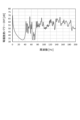
- FIG. 7 is a diagram showing the frequency response of the equivalent radiated power of a roof panel, obtained as an example of a vibration characteristic used to evaluate the vibration damping property of a target area for vibration noise reduction in this embodiment 1.
- FIG. 8 is a diagram showing (a) sensitivity determination elements remaining after sensitivity analysis using topology optimization, and (b) highly sensitive vehicle body parts having a large proportion of highly sensitive sensitivity determination elements in the first embodiment.
- FIG. 9 is a contour diagram showing the results of performing topography optimization on a highly sensitive vehicle body part in the first embodiment to determine an optimal uneven shape to be imparted to the surface of the highly sensitive vehicle body part.
- Figure 10 is a graph showing the frequency response of the equivalent radiated power of the roof panel for an automobile body before the body parts are modified to have a structure that increases their rigidity in this embodiment 1, and for an automobile body in which the rigidity has been modified by imparting an optimal uneven shape obtained by topography optimization to highly sensitive body parts that are highly sensitive to the vibration characteristics of the roof panel.
- the X-axis direction, the Y-axis direction, and the Z-axis direction respectively indicate the front-rear direction, the width direction, and the up-down direction of the vehicle body.
- An automobile body 100 includes automobile body parts such as automobile body frame parts and panel parts, as shown in Fig. 2 as an example.
- the automobile body frame parts are parts that constitute the automobile body frame, and examples thereof include a subframe 101 and a tunnel 103.
- the panel parts are outer panels and inner panels that are parts with a thin plate structure, and examples thereof include a roof panel 105, a floor panel 107, and a dash panel 109.
- the present invention performs sensitivity analysis on each body part of the automobile body 100 to determine which parts have a high contribution (sensitivity) to the vibration characteristics of the panel parts that are the target parts for vibration and noise reduction. For this reason, the body parts that make up the automobile body 100 are modeled using shell elements and/or solid elements in order to perform the sensitivity analysis.
- the element information and material properties of each body part that makes up the automobile body 100 are stored in an automobile body model file 61 ( Figure 1) that will be described later.
- Patent Document 3 a plate thickness configuration
- Patent Document 4 a material density distribution
- the inventors considered that there is a problem in that both of these methods optimize factors that affect both weight balance and stiffness balance, which affect vibration characteristics.
- the inventors therefore came up with a method of using optimization of stiffness balance in sensitivity analysis, instead of the sensitivity analysis methods disclosed in Patent Documents 3 and 4. Specifically, as a method of performing sensitivity analysis of vehicle body parts with respect to the vibration performance of the vehicle body parts, they came up with a method of performing optimization calculations by minimizing the effect of weight balance as a physical property value and using a virtual element that only has the effect of stiffness balance as a sensitivity determination element.
- the inventors also investigated an analytical method for selecting body parts with a structure that increases rigidity through sensitivity analysis of rigidity balance, in order to improve the vibration-damping properties of target areas for noise and vibration reduction without degrading other vehicle performance and without increasing weight.
- the present invention was made based on the above findings, and its specific configuration is as described below.
- the automobile body designing device designs an automobile body in which the body parts constituting the automobile body are modified to have a structure that increases the rigidity, thereby improving the vibration damping performance of the parts of the automobile body that are the target of vibration noise reduction.
- the automobile body designing device 1 is configured by a PC (personal computer) or the like, and includes a display device 3, an input device 5, a storage device 7, a working data memory 9, and a calculation processing unit 11.
- the display device 3, the input device 5, the storage device 7, and the working data memory 9 are connected to the calculation processing unit 11, and each function is executed by a command from the calculation processing unit 11.
- Each component of the automobile body designing device 1 will be described below.
- the display device 3 is used to display the analysis results, and is composed of an LCD monitor, etc.
- the input device 5 is used to give display instructions for the automobile body model file 61 and to input conditions by the operator, and is composed of a keyboard, mouse, etc.
- the storage device 7 is used to store various files such as the automobile body model file 61, and is composed of a hard disk, etc.
- the working data memory 9 is used to temporarily store and calculate data used by the calculation processing unit 11, and is composed of a RAM (Random Access Memory), etc.
- the calculation processing unit 11 includes a sensitivity analysis unit 21 and a high-rigidity structure determination unit 31.
- the calculation processing unit 11 is configured with a CPU (Central Processing Unit) such as a PC, and each of the above parts functions when the CPU executes a predetermined program. The function of each of the above units in the calculation processing unit 11 is explained below.
- CPU Central Processing Unit
- the sensitivity analysis unit 21 performs sensitivity analysis to determine the sensitivity of vehicle body parts in the automobile body 100 that can be modified to have a structure that increases rigidity, to vibration characteristics used to evaluate the vibration damping properties of the target areas for vibration and noise reduction.
- the sensitivity analysis unit 21 has a sensitivity analysis vehicle body model generation unit 23, a sensitivity determination element material property setting unit 25, a sensitivity analysis condition setting unit 27, and a sensitivity analysis unit 29.
- the sensitivity analysis vehicle body model generation unit 23 places sensitivity judgment elements in a two-dimensional space along the surface of a vehicle body part that can be modified to have a structure that increases rigidity, and connects the placed sensitivity judgment elements to the vehicle body part to generate a sensitivity analysis vehicle body model.
- the sensitivity determination elements can be arranged, for example, by dividing the two-dimensional space along the surface of the vehicle body part into elements using shell elements.
- connection between the sensitivity determination element arranged along the surface of the body part and the body part may be, for example, by connecting the nodes of the sensitivity determination element and the nodes of the body part with elements (rigid body elements, elastic body elements, or elasto-plastic body elements) (rigid joints or elastic joints).
- the sensitivity determination element and the body part may be connected by sharing nodes of the sensitivity determination element and the body part.
- the sensitivity determination element material property setting unit 25 sets the elastic coefficient and density as material properties of the sensitivity determination element in the sensitivity analysis vehicle body model.
- the elastic coefficient is set to a value equivalent to the metal material used in the vehicle body part in which the sensitivity determination element is arranged, and the density is set to a value small enough not to affect the vibration properties of the vibration noise reduction target portion in the sensitivity analysis vehicle body model.
- the purpose of the sensitivity analysis by the sensitivity analysis unit 21 is to obtain the sensitivity to the local stiffness of the vehicle body part. Therefore, the elastic coefficient set in the sensitivity determination element is not limited to the value of the elastic coefficient of a steel sheet itself.
- the density set for the sensitivity determination element must be a value that does not affect the weight of the shell element, which is the sensitivity determination element, and the vibration characteristics of the target area for vibration and noise reduction. For this reason, it is advisable to set the density value of the sensitivity determination element to 0.
- the density value of the sensitivity determination element is not limited to 0, and can be any value that does not affect the vibration characteristics of the target area for vibration and noise reduction.
- the plate thickness of the sensitivity determination element should be approximately the same as the portion of the vehicle body part where the sensitivity determination element is placed in an overlapping manner.
- the sensitivity analysis condition setting unit 27 sets vibration input conditions, an objective function, and constraint conditions as sensitivity analysis conditions.
- the vibration input conditions are conditions related to the vibrations given to the sensitivity analysis vehicle body model in the sensitivity analysis.
- the vibration input conditions can be set as amplitude (magnitude of vibration), frequency, and the part that gives vibration to the sensitivity analysis vehicle body model, and can be set appropriately assuming, for example, the vibration (road noise) input to the automobile body 100 via the tires when the automobile is driving.
- the part that gives vibration can be, for example, the connection part between the subframe 101 and the lower arm (not shown) in the sensitivity analysis vehicle body model (the part indicated by the ⁇ mark in Figure 2).
- the objective function is a condition that is set according to the vibration characteristics of the target part for vibration and noise reduction, and the vibration characteristics used to evaluate the vibration damping properties of the target part for vibration and noise reduction can be vibration intensity.
- the vibration intensity can be the frequency response value of either the acceleration, inertance, or equivalent radiation power in a specified frequency band of the target part for vibration and noise reduction.
- Inertance is a vibration characteristic expressed as the ratio of the force input to an object to the acceleration generated by it, and is also called the vibrational transfer function.
- Equivalent radiated power is an index that simply expresses the level of sound emitted by a vibrating structure, and is a vibration characteristic expressed based on the idea that the perpendicular component of the vibration velocity of a structure gives energy to the acoustic space.
- the objective function may be a function whose variables are acceleration, inertance, or equivalent radiation power in a specified frequency band of the target part for vibration noise reduction.
- An example of a function whose variables are acceleration, inertance, or equivalent radiation power is a function that gives the average or maximum value of acceleration, etc., at multiple positions in a body part (e.g., a panel part, etc.) that is the target for improving vibration damping.
- the portion of the target portion for vibration noise reduction for which vibration characteristics are evaluated may be set appropriately according to the operator's instructions. For example, if a panel component is the target portion for vibration noise reduction, the portion for which vibration characteristics are evaluated may be the entire surface of the panel component, or a specified portion of the panel component.
- the constraint condition is a constraint on the sensitivity judgment elements in the sensitivity analysis vehicle body model.
- a constraint condition on the sensitivity judgment elements for example, when topology optimization is applied to the sensitivity analysis by the sensitivity analysis unit 29 described below, a constraint can be set that the sensitivity judgment elements remaining after the optimization process are equal to or less than a predetermined volume ratio.
- the volume ratio of the sensitivity judgment elements may be the ratio of the volume occupied by the sensitivity judgment elements remaining after the optimization process of the topology optimization to the volume of the design space set for placing the sensitivity judgment elements.
- the sensitivity analysis section 29 performs sensitivity analysis under the sensitivity analysis conditions set by the sensitivity analysis condition setting section 27, and obtains the sensitivity of the sensitivity determination element with respect to the vibration characteristics of the target portion for vibration and noise reduction.
- topology optimization can be applied to the sensitivity analysis by the sensitivity analysis unit 29.
- the virtual material density of the sensitivity judgment element (virtual density representing the filling state of the material in each shell element) is used as the design variable.
- sensitivity judgment elements that contribute greatly to the vibration characteristics remain with a material density value close to 1, indicating high sensitivity to the vibration characteristics.
- sensitivity judgment elements that contribute little to the vibration characteristics are eliminated with a material density value close to 0, indicating low sensitivity to the vibration characteristics.
- the sensitivity analysis unit 29 can determine the material density calculated for each sensitivity judgment element as the sensitivity to the vibration characteristics.
- the high-rigidity structure determination unit 31 determines a structure that increases the rigidity of the vehicle body part based on the sensitivity of the vehicle body part determined by sensitivity analysis.
- the high-rigidity structure determination unit 31 can determine a structure that increases the rigidity of a vehicle body part by determining the positions of sensitivity determination elements with high sensitivity, determined by the sensitivity analysis unit 29, as areas to be changed to a structure that increases rigidity.
- the structure that increases the rigidity of the body part can be determined, for example, as a structure in which a concave-convex shape (bead) of a predetermined dimension is added to the part of the body part that corresponds to the high sensitivity determination element determined for the body part.
- the dimensions of the concave-convex shape can be set appropriately by the operator.
- a structure in which the concave-convex shape of the part corresponding to the high sensitivity determination element determined for the body part is changed to the concave-convex shape of the part directly, through sensitivity analysis by the sensitivity analysis unit 29, can be determined as the structure that increases the rigidity of the body part.
- the high-rigidity structure determination unit 31 may determine a structure that increases rigidity by changing the shape of the vehicle body part.
- the surface of the vehicle body part may have a character line-like surface structure like a door panel part.
- the high-rigidity structure determination unit 31 is not limited to providing uneven shapes to highly sensitive areas or changing the part shape, but may also perform topography optimization or topology optimization to determine a structure that increases the rigidity of the vehicle body part.
- Figure 3 shows the specific configurations of (a) the high-rigidity structure determination unit 41 that performs topography optimization, and (b) the high-rigidity structure determination unit 51 that performs topology optimization.
- High-rigidity structure determination unit 41 The high rigidity structure determination unit 41 shown in FIG. 3( a ) performs topography optimization to determine a structure that increases the rigidity of a body part, and includes a high-sensitivity body part selection unit 43 and a topography optimization analysis unit 45 .
- the high sensitivity vehicle body part selection unit 43 selects vehicle body parts having a high ratio of sensitivity determination elements with high sensitivity obtained by the sensitivity analysis unit 29 as high sensitivity vehicle body parts.
- the topography optimization analysis unit 45 performs topography optimization to determine an optimal uneven shape to be imparted to all or a part of the surface of the highly sensitive vehicle body part selected by the highly sensitive vehicle body part selection unit 43. Furthermore, the topography optimization analysis unit 45 determines a structure that enhances rigidity by imparting an uneven shape to the surface of the highly sensitive vehicle body part, based on the optimal uneven shape determined by the topography optimization.
- conditions related to the uneven shape (bead) to be imparted to the highly sensitive body part are set.
- conditions related to the uneven shape include the minimum width, maximum width, bead angle, and maximum bead height of the bead. These conditions related to the uneven shape can be set appropriately by the operator depending on interference with other body parts existing around the body part to which the bead is to be imparted, and the requirements of the automobile body.
- an objective function, constraint conditions, and vibration input conditions are set as optimization analysis conditions.
- the objective function and vibration input conditions should be set to the same vibration input conditions and objective function as the sensitivity analysis conditions set by the sensitivity analysis condition setting unit 27.
- constraint conditions should be set to constraints related to the uneven shape (for example, minimum and maximum bead widths, bead angles, maximum bead heights, etc.).
- the area where uneven shapes (beads) are imparted to the surface of highly sensitive body parts through topography optimization is preferably set to the areas where the surface of the body part is flat or nearly so.
- the unevenness of the beads with various inclinations imparted to the die after press molding can cause a problem where the die cannot be removed.
- beads are formed on the mating surface (flange portion) with other parts, gaps can occur, making joining difficult and reducing the joining strength.
- vibration noise occurs on flat or nearly flat parts of parts, it is possible to accurately prevent vibration noise by setting the area where uneven shapes (beads) are imparted to the surface of the body part where the surface is flat or nearly so, avoiding the areas where the above problems are likely to occur when beads are added.
- High-rigidity structure determination unit 51 The high-rigidity structure determination unit 51 shown in FIG. 3( b ) performs topology optimization to determine a structure that increases the rigidity of a vehicle body part, and includes a design space setting unit 53 and a topology optimization analysis unit 55 .
- the design space setting section 53 sets a design space for performing optimization analysis processing for vehicle body parts having a large proportion of sensitivity determination elements with high sensitivity obtained by the sensitivity analysis unit 21 .
- the design space setting unit 53 can, for example, remove body parts that have a large proportion of sensitivity determination elements with high sensitivity, and set the design space in the sensitivity analysis body model 110 in an area where the body parts have been removed.
- the design space setting unit 53 can be set along the surface of the body parts that have a large proportion of sensitivity determination elements with high sensitivity.
- the design space setting unit 53 may set a design space for each vehicle body part with high sensitivity, or may set a design space collectively for multiple vehicle body parts including a vehicle body part with high sensitivity.
- the topology optimization analysis unit 55 performs topology optimization to find an optimal shape of the vehicle body part for the design space set by the design space setting unit 53. Furthermore, the topology optimization analysis unit 55 determines a structure that enhances rigidity based on the optimal shape of the vehicle body part found by the topology optimization.
- topology optimization analysis unit 55 An example of a specific process for performing topology optimization by the topology optimization analysis unit 55 is as follows:
- an optimization analysis block model is generated that models the highly sensitive areas determined by the sensitivity analysis unit of the present invention using elements (solid elements or shell elements) and performs optimization analysis processing.
- the generated optimization analysis block model is combined with the sensitivity analysis vehicle body model to generate an optimization analysis model.
- the material properties (Young's modulus, specific gravity, density, etc.) of the optimization analysis block model are set to values equivalent to the material properties of the vehicle body parts.
- the objective function, constraint conditions, and vibration input conditions are set as optimization analysis conditions for the topology optimization analysis process.
- the objective function and vibration input conditions may be set to the same vibration input conditions and objective function as the sensitivity analysis conditions.
- the constraint conditions are constraints on the optimization analysis block model in topology optimization.
- the weight or volume ratio of the optimization block model may be set within a range that does not exceed the weight or volume of the area removed from the vehicle body part when setting the design space in the design space setting unit 53.
- a topology optimization analysis process is performed to find the optimal structure for the optimization analysis block model under the set optimization analysis conditions.
- a structure that increases the rigidity of the body part is determined based on the optimal structure of the optimized analysis block model obtained by topology optimization. For example, for areas where elements remain in the optimized analysis block model, a stiffening part can be added to that area in the original body part, and for areas where elements have been removed, an open hole can be provided, etc., to determine a structure that increases rigidity.
- a condition for maintaining the necessary rigidity may be set as an optimization constraint. Also, if there is concern about a decrease in crash performance, this can be addressed by replacing the materials used with materials of higher strength.
- the automobile body design method according to the first embodiment is a method in which a computer executes processing to design an automobile body in which the body parts constituting the automobile body are modified to have a structure that increases the rigidity, and the vibration damping performance of the target portion of the automobile body for vibration noise reduction is improved. As shown in Fig. 4, this processing includes a sensitivity analysis step S1 and a high-rigidity structure determination step S3.
- the automobile body design method according to the first embodiment is executed using an automobile body design device 1 (Fig. 1) configured by a computer.
- the sensitivity analysis step S1 is a step of performing sensitivity analysis for determining the sensitivity of vehicle body parts that can be modified to have a structure with increased rigidity to vibration characteristics used in evaluating the vibration-damping properties of the target portion for vibration and noise reduction.
- the sensitivity analysis step S1 includes a sensitivity analysis vehicle body model generation step S11, a sensitivity determination element material property setting step S13, a sensitivity analysis condition setting step S15, and a sensitivity analysis step S17.
- the sensitivity analysis step S1 is executed by the sensitivity analysis unit 21 of the automobile body design device 1.
- the sensitivity analysis vehicle body model generating step S11 is a step of arranging sensitivity judgment elements in a two-dimensional space along the surface of the vehicle body part and connecting the arranged sensitivity judgment elements to the vehicle body part to generate a sensitivity analysis vehicle body model.
- the sensitivity analysis vehicle body model generating step S11 is executed by the sensitivity analysis vehicle body model generating unit 23 of the automobile body design device 1.
- the sensitivity determination element material property setting step S13 is a step of setting an elastic coefficient and a density as material properties of the sensitivity determination element in the sensitivity analysis vehicle body model.
- the elastic coefficient is set to an elastic coefficient equivalent to the metal material used in the vehicle body parts, and the density is set to a value small enough not to affect the vibration properties of the vibration noise reduction target portion in the sensitivity analysis vehicle body model.
- the sensitivity determination element material property setting step S13 is executed by the sensitivity determination element material property setting unit 25 of the automobile body design device 1.
- the value of the density of the sensitivity determination element is not limited to 0, and may be appropriately set to a value that does not affect the vibration properties of the vibration noise reduction target portion.
- the sensitivity analysis condition setting step S15 is a step of setting a vibration input condition related to vibration given to the sensitivity analysis vehicle body model as a sensitivity analysis condition. Furthermore, the sensitivity analysis condition setting step S15 is a step of setting an objective function related to the vibration characteristics of the target portion for vibration noise reduction in the sensitivity analysis vehicle body model and a constraint condition related to the sensitivity judgment element in the sensitivity analysis vehicle body model as a sensitivity analysis condition. In the present embodiment 1, the sensitivity analysis condition setting step S15 is executed by the sensitivity analysis condition setting unit 27 of the automobile body design device 1.
- the vibration input conditions can be set by setting the amplitude (magnitude of vibration), frequency, and the part to which the vibration is applied to the sensitivity analysis vehicle body model, and can be set appropriately, for example, assuming the vibration (road noise) input to the automobile body 100 via the tires when the automobile is traveling.
- the vibration input conditions can be set to input a specified vibration to one or more parts of the sensitivity analysis vehicle body model.
- the objective function can be the minimization of the frequency response value of either the acceleration, inertance or equivalent radiated power in a specified frequency band of the part to be subjected to vibration noise reduction, or the minimization of a function with these as variables.
- a constraint condition for example, when topology optimization is applied to the sensitivity analysis in the sensitivity analysis step S17 described below, a constraint can be set that the sensitivity determination elements remaining after the optimization process are equal to or less than a predetermined volume ratio.
- the sensitivity analysis step S17 is to perform a sensitivity analysis under the sensitivity analysis conditions set in the sensitivity analysis condition setting step S15, and to obtain the sensitivity of the sensitivity determination element with respect to the vibration characteristics of the target part for vibration and noise reduction.
- the sensitivity analysis step S17 is executed by the sensitivity analysis unit 29 of the automobile body design device 1.
- topology optimization can be performed on the sensitivity determination elements placed on the vehicle body parts.
- the sensitivity determination elements in the vehicle body parts that remain after the topology optimization analysis process can be determined as parts of the vehicle body parts that are highly sensitive to the vibration characteristics of the target part for vibration and noise reduction.
- the high-rigidity structure determination step S3 is a step of determining a structure that increases the rigidity of the vehicle body part based on the sensitivity of the vehicle body part determined by the sensitivity analysis in the sensitivity analysis step S1.
- the high-rigidity structure determination step S3 is executed by the high-rigidity structure determination unit 31 of the automobile body design device 1.
- a structure that increases rigidity can be determined for the positions of the sensitivity determination elements with high sensitivity determined for the sensitivity determination elements of the vehicle body parts in the sensitivity analysis step S1.
- a structure in which a concave-convex shape (bead) of a predetermined dimension is added to a portion of the body part that corresponds to a sensitivity determination element with a high sensitivity determined for the body part can be determined as a structure that increases the rigidity of the body part.
- the dimensions of the concave-convex shape can be set appropriately.
- a structure obtained by simply modifying the shape of the part of the body part that corresponds to the sensitivity determination element with high sensitivity determined for the body part may be determined as the structure that increases the rigidity of the body part.
- the high-rigidity structure determination step it is not limited to providing uneven shapes to highly sensitive areas or changing the part shape, but topography optimization or topology optimization may be performed to determine a structure that increases the rigidity of the vehicle body part.
- Figure 5 shows the specific configurations of the high-rigidity structure determination step S4, which performs topography optimization, and the high-rigidity structure determination step S5, which performs topology optimization.
- the high-rigidity structure determination step S4 shown in Fig. 5(a) performs topography optimization to determine a structure that enhances the rigidity of the body parts, and includes a high-sensitivity body part selection step S41 and a topography optimization analysis step S43.
- the high-rigidity structure determination step S4 shown in Fig. 5(a) is executed by the high-rigidity structure determination unit 41 shown in Fig. 3(a).
- the high sensitivity body part selection step S41 is a step of selecting, as a high sensitivity body part, a body part having a high ratio of sensitivity determination elements having high sensitivity determined in the sensitivity analysis step S17 from among the body parts.
- the high sensitivity body part selection step S41 can be executed by the high sensitivity body part selection unit 43 of the automobile body design device 1 (FIG. 3(a)).
- the topography optimization analysis step S43 is a step of implementing topography optimization to determine an optimal uneven shape to be imparted to the surface of the highly sensitive vehicle body part selected in the highly sensitive vehicle body part selection step S41. Furthermore, the topography optimization analysis step S43 is a step of determining a structure that enhances rigidity by imparting an uneven shape to the surface of the highly sensitive vehicle body part based on the optimal uneven shape determined by the topography optimization.
- the topography optimization analysis step S43 can be executed by the topography optimization analysis unit 45 of the automobile body design device 1 (FIG. 3(a)).
- the high-rigidity structure determination step S5 shown in FIG. 5( b) shows the configuration of a step of performing topology optimization to determine a structure that increases the rigidity of the vehicle body part, and includes a design space setting step S51 and a topology optimization analysis step S53.
- the design space setting step S51 is to set a design space for performing an optimization analysis process for vehicle body parts having a large ratio of sensitivity determination elements with high sensitivity determined in the sensitivity analysis step S1 among the vehicle body parts.
- the design space setting step S51 can be executed by a design space setting section 53 of a high-rigidity structure determination unit 51 shown in FIG.
- the design space setting process S51 for example, body parts with a large proportion of sensitivity determination elements with high sensitivity can be removed, and the design space can be set in an area in the sensitivity analysis body model 110 where the body parts have been removed.
- the design space can be set along the surface of the body parts with a large proportion of sensitivity determination elements with high sensitivity.
- a design space may be set for each vehicle body part with high sensitivity, or a design space may be set collectively for multiple vehicle body parts including a vehicle body part with high sensitivity.
- the topology optimization analysis step S53 is to perform topology optimization for determining an optimal shape of the vehicle body part for the design space set in the design space setting step S51. Furthermore, the topology optimization analysis step S53 is to determine a structure that increases rigidity based on the optimal shape of the vehicle body part determined by the topology optimization. The topology optimization analysis step S53 is executed by the topology optimization analysis part 55 of the high rigidity structure determination unit 51 shown in FIG. 3(b), and can determine a structure that increases rigidity of the vehicle body part.
- mesh data (mesh model) of each vehicle body part constituting the vehicle body 100 was obtained from the vehicle body model file 61 stored in the storage device 7. Then, vehicle body parts other than the exterior panels such as the roof panel 105 were selected as vehicle body parts that can be modified to have a structure that increases rigidity.
- sensitivity judgment elements are placed in two-dimensional space along the surfaces of body parts other than exterior panels such as the roof panel 105.
- sensitivity judgment elements are placed for all body parts, and the body parts corresponding to Figure 8(a) described below are given the reference numbers 111, 113, 117, and 119.
- the placed sensitivity judgment elements are then connected to the body parts to generate the sensitivity analysis body model 110.
- the sensitivity judgment elements are shell elements, and are connected to the body parts by rigid body beam elements.
- material properties were set for the sensitivity determination elements in the sensitivity analysis vehicle body model 110.
- the elastic modulus was set to the elastic modulus of the steel plate used in each vehicle body part (210 GPa), and the density was set to 0.
- the vibration input conditions, objective function, constraint conditions, and vibration input conditions were set.
- the vibration input conditions were set to simulate road noise while the vehicle is moving, with vibration of amplitude 1N and frequency 1 to 200Hz being input to the joint (part marked with a triangle in Figure 2) between the subframe 101 and the lower arm (not shown) in the sensitivity analysis vehicle body model 110.
- the objective function was set to minimize the peak value of the equivalent radiated power ERP of the roof panel 105 in the frequency band from 110 Hz to 180 Hz.
- Figure 7 shows the frequency response value of the equivalent radiated power of the roof panel 105 when the above vibration input conditions were applied to the automobile body 100.
- the constraint condition was set to a volume ratio of the sensitivity determination element of 10% or less.
- the sensitivity analysis conditions set as described above were applied to the sensitivity analysis vehicle body model 110, and sensitivity analysis was performed.
- Figure 8(a) shows the results of the remaining sensitivity determination elements after performing the sensitivity analysis. It can be seen that the proportion of remaining sensitivity determination elements (111, 113, 117, and 119) is large in the subframe 101, tunnel 103, floor panel 107, and dash panel 109.
- step S4 of determining a high-rigidity structure which involves optimizing the topography, a structure that increases the rigidity of the body parts was determined.
- body parts that are highly sensitive to the vibration characteristics of the roof panel 105 were selected as highly sensitive body parts.
- part of the subframe 101, the tunnel 103, the floor panel 107, and the dash panel 109 were selected as highly sensitive body parts 131, 133, 137, and 139, as shown in FIG. 8(b).
- topography optimization was performed to determine the optimal uneven shape to be imparted to the surface of the highly sensitive vehicle body part.
- the constraints on the uneven shape were set to a minimum width of 15 mm, a maximum width of 30 mm, a bead angle of 80°, and a maximum bead height of 7 mm.
- the same vibration input conditions and objective function as the sensitivity analysis conditions were set as the optimization analysis conditions in the topography optimization.
- Figure 9 shows the results of finding the optimal distribution of concave-convex shapes by topography optimization for highly sensitive vehicle body parts (131, 133, 137, 139) under the above conditions related to the concave-convex shapes and the optimization analysis conditions.
- FIG. 10 shows the frequency response results of the equivalent radiated power of the roof panel 105 when the above vibration input conditions were applied to the automobile body 100 in which the tunnel 103, floor panel 107, and dash panel 109 were modified to increase rigidity.
- Figure 10 also shows the results ( Figure 7) of the frequency response of the equivalent radiated power of the roof panel 105 for the automobile body 100 before the structures of the tunnel 103, floor panel 107, and dash panel 109 were modified.
- the maximum equivalent radiated power in the frequency band from 110 Hz to 180 Hz decreased by 1.6 dB (before structural modification: 67.5 dB, after changing to high-rigidity structure: 65.9 dB), indicating that the vibration damping properties of the roof panel 105 improved.
- the vibration-damping properties of the roof panel 105 were also evaluated when a structure in which uneven shapes were applied to the parts of each body part that correspond to the high sensitivity determination elements determined for that part was determined to be the structure that increases the rigidity of the body part (high rigidity structure determination step S3).
- a structure in which uneven shapes of about 5.0 mm in height were applied to the parts of part of the subframe 101, the tunnel 103, the floor panel 107, and the dash panel 109 that correspond to the high sensitivity determination elements was determined to be the high rigidity structure.
- the frequency response of the equivalent radiated power of the roof panel 105 was determined for the automobile body 100 modified to the high-rigidity structure determined in this way.
- the maximum value in the frequency band from 110 Hz to 180 Hz decreased by 1.0 dB (before structural modification: 67.5 dB, after structural modification: 66.5 dB, not shown). From these results, it was found that when an uneven shape was provided to the parts corresponding to the sensitivity determination elements with high sensitivity based on sensitivity analysis, a significant improvement in the vibration damping properties of the roof panel 105 was observed, although the effect was less than when an uneven shape with the optimal shape determined by topography optimization was provided.
- the vibration damping properties of the roof panel 105 were evaluated when highly sensitive body parts were selected based on sensitivity analysis, and a high rigidity structure was determined by performing topology optimization on the selected highly sensitive body parts (high rigidity structure determination step S5).
- a part of the subframe 101, the tunnel 103, the floor panel 107, and the dash panel 109 were selected as highly sensitive body parts 131, 133, 137, and 139.
- a design space consisting of three-dimensional solid elements was set in the vicinity of each highly sensitive body part, the remaining shape was obtained by topology optimization, and the high rigidity structure of the highly sensitive body part was determined based on the remaining shape.
- the optimization analysis conditions for topology optimization to obtain the remaining shape of the highly sensitive body part were the same vibration input conditions and objective function as the sensitivity analysis conditions.
- a sensitivity analysis is performed on the body parts of an automobile body to determine the degree of contribution (sensitivity) of local stiffness to the vibration characteristics of the target parts for vibration and noise reduction without considering the influence of weight.
- the sensitivity to the vibration damping properties of the target parts for vibration and noise reduction is determined not only for the target parts for vibration and noise reduction such as panel parts, but also for the body frame parts and reinforcing parts from the vibration source in the automobile to the target parts for vibration and noise reduction.
- a structure that increases the stiffness of the body parts is determined based on the sensitivity determined by the sensitivity analysis. This makes it possible to design an automobile body with improved vibration damping properties of the target parts for vibration and noise reduction without reducing other vehicle performance such as body stiffness and crash performance, and without increasing weight.
- the above description of the first embodiment of the present invention has been about an automobile body design method and device.
- the present invention can also be configured as an automobile body design program that causes each unit in the arithmetic processing unit 11 of the automobile body design device 1 (FIG. 1) configured by a computer to function.
- the automobile body design program according to the first embodiment is for designing an automobile body in which the body parts that make up the automobile body are modified to have a structure that increases the rigidity, thereby improving the vibration-damping properties of the parts of the automobile body that are the target of vibration noise reduction.
- the automobile body design program according to the first embodiment causes a computer to function as a sensitivity analysis unit 21 and a high-rigidity structure determination unit 31, like the arithmetic processing unit 11 shown in FIG. 1.
- the automobile body design program causes the computer to function as the sensitivity analysis unit 21, and causes each part of the sensitivity analysis unit 21 to function.
- the sensitivity analysis unit 21 has a sensitivity analysis body model generation part 23, a sensitivity determination element material property setting part 25, a sensitivity analysis condition setting part 27, and a sensitivity analysis part 29.
- the high-rigidity structure determination unit 31 shown in Figure 1 functions to determine a structure that increases the rigidity of the vehicle body parts by, for example, adding uneven shapes to the areas with high sensitivity determined by the sensitivity analysis unit 29.
- the automobile body design program according to the first embodiment may have a function of causing a computer to execute the program as the high-rigidity structure determination unit 41 shown in FIG. 3(a).
- the automobile body design program according to the first embodiment causes the high-rigidity structure determination unit 41 (FIG. 3(b)) to function as a high-sensitivity body part selection unit 43 and a topography optimization analysis unit 45.
- the automobile body design program according to the first embodiment may cause the computer to function as the high-rigidity structure determination unit 51 shown in FIG. 3(b).
- the automobile body design program according to the first embodiment causes the high-rigidity structure determination unit 51 (FIG. 3(b)) to function as the design space setting unit 53 and the topology optimization analysis unit 55.
- sensitivity judgment elements are first placed in two-dimensional space along the surface of the body parts in the automobile body, and a sensitivity analysis body model is generated.
- the material properties are set to an elastic modulus equivalent to the metal plate used in the vehicle part in which the sensitivity determination element is located, and a density value small enough so as not to affect the vibration characteristics of the target area for vibration and noise reduction.
- sensitivity analysis conditions are set in the same way as in sensitivity analysis using topology optimization.
- an analysis process is run to optimize the thickness of the sensitivity judgment elements in the sensitivity analysis vehicle model, and the optimal thickness is calculated for each sensitivity judgment element placed on the vehicle part.
- sensitivity determination elements in which the plate thickness obtained by plate thickness optimization is greater than the original plate thickness indicate a high sensitivity to the vibration characteristics of the target part for vibration and noise reduction
- sensitivity determination elements in which the plate thickness is less than the original plate thickness indicate a low sensitivity to the vibration characteristics of the target part for vibration and noise reduction.
- the sensitivity is calculated for each sensitivity determination element, but the present invention may also calculate the sensitivity for each vehicle body part.
- a structure that increases the rigidity of the entire vehicle body part with high sensitivity may be determined.
- a structure that increases the rigidity may be determined for the vehicle body part with high sensitivity by performing topography optimization or topology optimization.
- the manufacturing method of an automobile body according to embodiment 2 of the present invention involves modifying the body parts that make up the automobile body to have a structure that increases the rigidity, thereby manufacturing an automobile body that has improved vibration damping properties in areas of the automobile body that are targets for vibration and noise reduction.
- the automobile body design method according to the first embodiment described above is used to determine a structure that will increase the rigidity of the body parts based on their sensitivity to the vibration characteristics used to evaluate the vibration damping properties of the target area for vibration and noise reduction.
- a structure that increases rigidity may be one in which highly sensitive areas are given an uneven shape as determined by sensitivity analysis, or one in which the shape of highly sensitive areas is changed.
- a structure that increases rigidity may be determined by selecting a body part that has a high ratio of sensitivity determination elements with high sensitivity determined by sensitivity analysis as a highly sensitive body part, and determining the optimal uneven shape to be imparted to the surface of the highly sensitive body part by topography optimization.
- a design space may be set for vehicle body parts with a large proportion of sensitivity determination elements with high sensitivity determined by sensitivity analysis, and a structure that increases the rigidity of the vehicle body parts may be determined by topology optimization.
- the structure for increasing rigidity is a structure in which a concave-convex shape (bead) is added to a body part, and it is difficult to manufacture a body part with a concave-convex shape (bead), a smoothing process may be further performed to meet the constraints of manufacturing the actual body part.
- a smoothing process may be further performed to meet the constraints of manufacturing the actual body part.
- the vehicle body parts are manufactured with the structure that enhances the rigidity thus determined.
- the vehicle body part can be manufactured by simultaneously giving the concave-convex shape during the process of manufacturing the vehicle body part by press forming.
- three-dimensional position data of the structure that enhances rigidity is input into a CAD/CAM program linked to an NC machine tool (numerically-controlled machine), and the CAD data of the corresponding vehicle body part is changed.
- NC data of a press forming die is created, and converted into NC data (numerical control data) (NC program) for NC machining.
- NC machine tool machines a casting mold model made of expanded polystyrene or a steel mold using the full mold casting method (evaporative pattern casting method).
- NC data NC program
- the NC machine tool produces a casting mold model made of expanded polystyrene or a steel mold. This makes it possible to manufacture press forming dies to be used in the actual press forming process to manufacture car body parts with a structure that increases rigidity.
- the method for manufacturing an automobile body according to the second embodiment makes it possible to manufacture an automobile body with improved vibration-damping properties in the areas that require noise and vibration reduction without reducing the body's rigidity, crashworthiness, and other vehicle performance, and without increasing its weight.
- the present invention provides an automobile body design method, device, and program for designing an automobile body with improved vibration-damping properties in areas that require vibration and noise reduction without compromising vehicle performance, as well as a method for manufacturing an automobile body.
Landscapes
- Engineering & Computer Science (AREA)
- Physics & Mathematics (AREA)
- Geometry (AREA)
- Theoretical Computer Science (AREA)
- General Physics & Mathematics (AREA)
- Computer Hardware Design (AREA)
- General Engineering & Computer Science (AREA)
- Evolutionary Computation (AREA)
- Mathematical Optimization (AREA)
- Pure & Applied Mathematics (AREA)
- Mathematical Analysis (AREA)
- Computational Mathematics (AREA)
- Automation & Control Theory (AREA)
- Aviation & Aerospace Engineering (AREA)
- Chemical & Material Sciences (AREA)
- Combustion & Propulsion (AREA)
- Transportation (AREA)
- Mechanical Engineering (AREA)
- Body Structure For Vehicles (AREA)
- Measurement Of Mechanical Vibrations Or Ultrasonic Waves (AREA)
- Automobile Manufacture Line, Endless Track Vehicle, Trailer (AREA)
Abstract
Description
自動車車体100は、一例として図2に示すように、車体骨格部品やパネル部品等の車体部品を備える。車体骨格部品は、自動車の車体骨格を構成する部品であり、サブフレーム101、トンネル103等が例示できる。パネル部品は、薄板構造の部品である外板パネル(outer panel)や内板パネル(inner panel)であり、ルーフパネル105、フロアパネル107、ダッシュパネル109等が例示できる。
特許文献3及び特許文献4に開示されている感度解析は、前述したように、最適化手法を適用し、振動特性を向上させる板厚構成(特許文献3)、材料密度分布(特許文献4)を求めるものである。しかしながら、発明者は、いずれも、振動特性に影響する重量バランスと剛性バランスの両方に影響する因子を最適化の対象としている点に問題があると考えた。
<自動車車体設計装置>
本発明の実施の形態1に係る自動車車体設計装置は、自動車車体を構成する車体部品を剛性を高める構造に変更し、自動車車体における振動騒音低減対象部位の制振性を向上させた自動車車体を設計するものである。自動車車体設計装置1は、一例として図1に示すように、PC(パーソナルコンピュータ)等によって構成され、表示装置3と、入力装置5と、記憶装置7と、作業用データメモリ9と、演算処理部11と、を備えている。表示装置3、入力装置5、記憶装置7及び作業用データメモリ9は、演算処理部11に接続され、演算処理部11からの指令によってそれぞれの機能が実行される。以下、自動車車体設計装置1の各構成について説明する。
感度解析ユニット21は、自動車車体100における車体部品のうち剛性を高める構造に変更可能な車体部品について、振動騒音低減対象部位の制振性の評価に用いる振動特性に対する感度を求める感度解析を行うものである。
感度解析車体モデル生成部23は、剛性を高める構造に変更可能な車体部品の表面に沿う二次元空間に感度判定要素を配置し、配置した感度判定要素を車体部品に結合して感度解析車体モデルを生成するものである。
感度判定要素材料特性設定部25は、感度解析車体モデルにおける感度判定要素の材料特性として、弾性係数と、密度と、を設定するものである。弾性係数は、感度判定要素が配置された車体部品に用いられている金属材料に相当する値を設定し、密度は、感度解析車体モデルにおける振動騒音低減対象部位の振動特性に影響が生じない程度に小さい値を設定する。
感度解析条件設定部27は振動入力条件と、目的関数と、制約条件と、を感度解析条件として設定するものである。
感度解析部29は、感度解析条件設定部27により設定された感度解析条件の下で感度解析を行い、振動騒音低減対象部位の振動特性に対する感度判定要素の感度を求めるものである。
高剛性構造決定ユニット31は、感度解析により車体部品について求めた感度に基づいて、車体部品の剛性を高める構造を決定するものである。
図3(a)に示す高剛性構造決定ユニット41は、トポグラフィー最適化を行い、車体部品の剛性を高める構造を決定するものであり、高感度車体部品選定部43と、トポグラフィー最適化解析部45と、を有する。
高感度車体部品選定部43は、感度解析部29により求めた感度が高い感度判定要素の割合の大きい車体部品を高感度車体部品として選定するものである。
トポグラフィー最適化解析部45は、高感度車体部品選定部43により選定された高感度車体部品の表面の全部又は一部に付与する最適な凹凸形状を求めるトポグラフィー最適化を実施するものである。さらに、トポグラフィー最適化解析部45は、トポグラフィー最適化により求めた最適な凹凸形状に基づいて、高感度車体部品の表面に凹凸形状を付与することにより剛性を高める構造を決定するものである。
図3(b)に示す高剛性構造決定ユニット51は、トポロジー最適化を行い、車体部品の剛性を高める構造を決定するものであり、設計空間設定部53と、トポロジー最適化解析部55と、を有する。
設計空間設定部53は、感度解析ユニット21により求めた感度が高い感度判定要素の割合の大きい車体部品について、最適化の解析処理を行うための設計空間を設定するものである。
トポロジー最適化解析部55は、設計空間設定部53により設定された設計空間に対して、車体部品の最適な形状を求めるトポロジー最適化を実施するものである。さらに、トポロジー最適化解析部55は、トポロジー最適化により求めた車体部品の最適な形状に基づいて剛性を高める構造を決定するものである。
本実施の形態1に係る自動車車体設計方法は、自動車車体を構成する車体部品を剛性を高める構造に変更し、自動車車体における振動騒音低減対象部位の制振性を向上させた自動車車体を設計するために、コンピュータが処理を実行するものである。この処理は、図4に示すように、感度解析ステップS1と、高剛性構造決定ステップS3と、を含む。本実施の形態1に係る自動車車体設計方法は、コンピュータによって構成された自動車車体設計装置1(図1)を用いて実行するものとする。
感度解析ステップS1は、車体部品のうち剛性を高める構造に変更可能な車体部品について、振動騒音低減対象部位の制振性の評価に用いる振動特性に対する感度を求める感度解析を行うステップである。感度解析ステップS1は、図4に示すように、感度解析車体モデル生成工程S11と、感度判定要素材料特性設定工程S13と、感度解析条件設定工程S15と、感度解析工程S17と、を有する。本実施の形態1において、感度解析ステップS1は、自動車車体設計装置1の感度解析ユニット21が実行する。
感度解析車体モデル生成工程S11は、車体部品の表面に沿う二次元空間に感度判定要素を配置し、配置した感度判定要素を車体部品に結合して感度解析車体モデルを生成する工程である。本実施の形態1において、感度解析車体モデル生成工程S11は、自動車車体設計装置1の感度解析車体モデル生成部23が実行する。
感度判定要素材料特性設定工程S13は、感度解析車体モデルにおける感度判定要素の材料特性として、弾性係数と、密度と、を設定する工程である。弾性係数は、車体部品に用いられている金属材料に相当する弾性係数を設定し、密度は、感度解析車体モデルにおける前記振動騒音低減対象部位の振動特性に影響が生じない程度に小さい値を設定する。本実施の形態1において、感度判定要素材料特性設定工程S13は、自動車車体設計装置1の感度判定要素材料特性設定部25が実行する。感度判定要素の密度の値は0に限定されるものではなく、振動騒音低減対象部位の振動特性に影響しない程度の値を適宜設定してもよい。
感度解析条件設定工程S15は、感度解析車体モデルに与える振動に関する振動入力条件と、を感度解析条件として設定する工程である。さらに、感度解析条件設定工程S15は、感度解析車体モデルにおける振動騒音低減対象部位の振動特性に関する目的関数と、感度解析車体モデルにおける前記感度判定要素に関する制約条件と、を感度解析条件として設定する工程である。本実施の形態1において、感度解析条件設定工程S15は、自動車車体設計装置1の感度解析条件設定部27が実行する。
感度解析工程S17は、感度解析条件設定工程S15において設定された感度解析条件の下で感度解析を行い、振動騒音低減対象部位の振動特性に対する感度判定要素の感度を求めるものである。本実施の形態1において、感度解析工程S17は、自動車車体設計装置1の感度解析部29が実行する。
高剛性構造決定ステップS3は、感度解析ステップS1における感度解析により車体部品について求めた感度に基づいて、車体部品の剛性を高める構造を決定するステップである。本実施の形態1において、高剛性構造決定ステップS3は、自動車車体設計装置1の高剛性構造決定ユニット31が実行する。
図5(a)に示す高剛性構造決定ステップS4は、トポグラフィー最適化を行い、車体部品の剛性を高める構造を決定するものであり、高感度車体部品選定工程S41と、トポグラフィー最適化解析工程S43と、を有する。そして、図5(a)に示す高剛性構造決定ステップS4は、図3(a)に示した高剛性構造決定ユニット41が実行する。
高感度車体部品選定工程S41は、車体部品のうち、感度解析工程S17において求めた感度が高い感度判定要素の割合の大きい車体部品を高感度車体部品として選定する工程である。高感度車体部品選定工程S41は、自動車車体設計装置1の高感度車体部品選定部43が実行することができる(図3(a))。
トポグラフィー最適化解析工程S43は、高感度車体部品選定工程S41において選定された高感度車体部品の表面に付与する最適な凹凸形状を求めるトポグラフィー最適化を実施するものである。さらに、トポグラフィー最適化解析工程S43は、トポグラフィー最適化により求めた最適な凹凸形状に基づいて、高感度車体部品の表面に凹凸形状を付与することにより剛性を高める構造を決定するものである。トポグラフィー最適化解析工程S43は、自動車車体設計装置1のトポグラフィー最適化解析部45が実行することができる(図3(a))。
図5(b)に示す高剛性構造決定ステップS5は、トポロジー最適化を行い、車体部品の剛性を高める構造を決定するステップの構成を示すものであり、設計空間設定工程S51と、トポロジー最適化解析工程S53と、を有する。
設計空間設定工程S51は、車体部品のうち、感度解析ステップS1により求めた感度が高い感度判定要素の割合の大きい車体部品について、最適化の解析処理を行うための設計空間を設定するものである。設計空間設定工程S51は、図3(b)に示す高剛性構造決定ユニット51の設計空間設定部53により実行することができる。
トポロジー最適化解析工程S53は、設計空間設定工程S51において設定された設計空間に対して、車体部品の最適な形状を求めるトポロジー最適化を実施するものである。さらに、トポロジー最適化解析工程S53は、トポロジー最適化により求めた車体部品の最適な形状に基づいて剛性を高める構造を決定するものである。トポロジー最適化解析工程S53は、図3(b)に示す高剛性構造決定ユニット51のトポロジー最適化解析部55により実行し、車体部品の剛性を高める構造を決定することができる。
次に、本実施の形態1に係る自動車車体設計方法及び装置の作用効果を説明する。ここでは、図2に示す自動車車体100の振動騒音低減対象部位としてルーフパネル105の制振性を向上させるために車体部品の剛性を高める構造を決定する場合について、本実施の形態1に係る自動車車体設計方法における処理を説明する。以下の説明は、自動車車体設計方法の作用効果に関するものであるが、本実施の形態1に係る自動車車体設計装置1によっても同様の作用効果が得られる。
上記の本発明の実施の形態1に係る説明は、自動車車体設計方法及び装置についてのものであった。もっとも、本発明は、コンピュータによって構成された自動車車体設計装置1(図1)の演算処理部11における各部を機能させる自動車車体設計プログラムとして構成することができる。
本発明の実施の形態2に係る自動車車体の製造方法は、自動車車体を構成する車体部品を剛性を高める構造に変更し、自動車車体における振動騒音低減対象部位の制振性を向上させた自動車車体を製造するものである。
3 表示装置
5 入力装置
7 記憶装置
9 作業用データメモリ
11 演算処理部
21 感度解析ユニット
23 感度解析車体モデル生成部
25 感度判定要素材料特性設定部
27 感度解析条件設定部
29 感度解析部
31 高剛性構造決定ユニット
41 高剛性構造決定ユニット
43 高感度車体部品選定部
45 トポグラフィー最適化解析部
51 高剛性構造決定ユニット
53 設計空間設定部
55 トポロジー最適化解析部
61 自動車車体モデルファイル
100 自動車車体
101 サブフレーム
103 トンネル
105 ルーフパネル
107 フロアパネル
109 ダッシュパネル
110 感度解析車体モデル
111、113、115、117 感度判定要素
121、123、125、127 トポロジー最適化により残存した感度判定要素
131、133、137、139 高感度車体部品
Claims (8)
- 自動車車体を構成する車体部品を剛性を高める構造に変更し、前記自動車車体における振動騒音低減対象部位の制振性を向上させた自動車車体を設計するために、コンピュータが処理を実行する自動車車体設計方法であって、
前記処理は、
剛性を高める構造に変更可能な車体部品について、前記振動騒音低減対象部位の制振性の評価に用いる振動特性に対する感度を求める感度解析を行う感度解析ステップと、
前記感度解析により前記車体部品について求めた感度に基づいて、前記車体部品の剛性を高める構造を決定する高剛性構造決定ステップと、
を含み、
前記感度解析ステップは、
前記車体部品の表面に沿う二次元空間に感度判定要素を配置し、該配置した感度判定要素を前記車体部品に結合して感度解析車体モデルを生成する感度解析車体モデル生成工程と、
前記感度解析車体モデルにおける前記感度判定要素の材料特性として、前記車体部品に用いられている金属材料に相当する弾性係数と、前記感度解析車体モデルにおける前記振動騒音低減対象部位の振動特性に影響が生じない程度に小さい値の密度と、を設定する感度判定要素材料特性設定工程と、
前記感度解析における感度解析条件として、前記感度解析車体モデルに与える振動に関する振動入力条件と、前記感度解析車体モデルにおける前記振動騒音低減対象部位の振動特性に関する目的関数と、前記感度解析車体モデルにおける前記感度判定要素に関する制約条件と、を設定する感度解析条件設定工程と、
該設定された感度解析条件の下で前記感度解析を行い、前記振動騒音低減対象部位の振動特性に対する前記感度判定要素の感度を求める感度解析工程と、
を含む、自動車車体設計方法。 - 前記感度解析条件設定工程において、
前記振動入力条件を、前記感度解析車体モデルに対して1又は2以上の部位に所定の振動を入力、とし、
前記目的関数を、前記振動騒音低減対象部位の所定の周波数帯における加速度、イナータンス又は等価放射パワーのいずれかの周波数応答値の最小化、又はこれらを変数とする関数の最小化、とし、
前記制約条件を、前記感度判定要素の体積率を所定の値以下、とし、
前記感度解析工程において、
前記車体部品に配置した感度判定要素についてトポロジー最適化を行い、該トポロジー最適化の解析処理により残存した前記車体部品における感度判定要素を、該車体部品において前記振動騒音低減対象部位の振動特性に対する感度が高い部位として求める、
請求項1に記載の自動車車体設計方法。 - 前記高剛性構造決定ステップにおいて、前記車体部品について求めた感度が高い前記感度判定要素に対応する部位に所定の寸法の凹凸形状を付与した構造を、該車体部品の剛性を高めた構造として決定する、請求項1又は2に記載の自動車車体設計方法。
- 前記高剛性構造決定ステップは、
前記車体部品のうち、前記感度解析で求めた感度が高い前記感度判定要素の割合の大きい車体部品を高感度車体部品として選定する高感度車体部品選定工程と、
該選定された高感度車体部品の表面に付与する最適な凹凸形状を求めるトポグラフィー最適化を実施し、該トポグラフィー最適化により求めた最適な凹凸形状に基づいて、前記高感度車体部品の剛性を高める構造を決定するトポグラフィー最適化解析工程と、
を含む、請求項1又は2に記載の自動車車体設計方法。 - 前記高剛性構造決定ステップは、
前記車体部品のうち、前記感度解析で求めた感度が高い前記感度判定要素の割合の大きい車体部品を選定し、該選定した車体部品の表面に沿って設計空間を設定する設計空間設定工程と、
前記設計空間が設定された前記車体部品の最適な形状を求めるトポロジー最適化を実施し、該トポロジー最適化により求めた前記車体部品の最適な形状に基づいて該車体部品の剛性を高める構造を決定するトポロジー最適化解析工程と、
を含む、請求項1又は2に記載の自動車車体設計方法。 - 自動車車体を構成する車体部品を剛性を高める構造に変更し、前記自動車車体における振動騒音低減対象部位の制振性を向上させた自動車車体を設計する自動車車体設計装置であって、
剛性を高める構造に変更可能な車体部品について、前記振動騒音低減対象部位の制振性の評価に用いる振動特性に対する感度を求める感度解析を行う感度解析ユニットと、
前記感度解析により前記車体部品について求めた感度に基づいて、前記車体部品の剛性を高める構造を決定する高剛性構造決定ユニットと、
を備え、
前記感度解析ユニットは、
前記車体部品の表面に沿う二次元空間に感度判定要素を配置し、該配置した感度判定要素を前記車体部品に結合して感度解析車体モデルを生成する感度解析車体モデル生成部と、
前記感度解析車体モデルにおける前記感度判定要素の材料特性として、前記車体部品に用いられている金属材料に相当する弾性係数と、前記感度解析車体モデルにおける前記振動騒音低減対象部位の振動特性に影響が生じない程度に小さい値の密度と、を設定する感度判定要素材料特性設定部と、
前記感度解析における感度解析条件として、前記感度解析車体モデルに与える振動に関する振動入力条件と、前記感度解析車体モデルにおける前記振動騒音低減対象部位の振動特性に関する目的関数と、前記感度解析車体モデルにおける前記感度判定要素に関する制約条件と、を設定する感度解析条件設定部と、
該設定された感度解析条件の下で前記感度解析を行い、前記振動騒音低減対象部位の振動特性に対する前記感度判定要素の感度を求める感度解析部と、
を有する、自動車車体設計装置。 - 自動車車体を構成する車体部品を剛性を高める構造に変更し、前記自動車車体における振動騒音低減対象部位の制振性を向上させた自動車車体を設計する自動車車体設計プログラムであって、
コンピュータを、
剛性を高める構造に変更可能な車体部品について、前記振動騒音低減対象部位の制振性の評価に用いる振動特性に対する感度を求める感度解析を行う感度解析ユニットと、
前記感度解析により前記車体部品について求めた感度に基づいて、前記車体部品の剛性を高める構造を決定する高剛性構造決定ユニットと、
として機能させ、
前記感度解析ユニットは、
前記車体部品の表面に沿う二次元空間に感度判定要素を配置し、該配置した感度判定要素を前記車体部品に結合して感度解析車体モデルを生成する感度解析車体モデル生成部と、
前記感度解析車体モデルにおける前記感度判定要素の材料特性として、前記車体部品に用いられている金属材料に相当する弾性係数と、前記感度解析車体モデルにおける前記振動騒音低減対象部位の振動特性に影響が生じない程度に小さい値の密度と、を設定する感度判定要素材料特性設定部と、
前記感度解析における感度解析条件として、前記感度解析車体モデルに与える振動に関する振動入力条件と、前記感度解析車体モデルにおける前記振動騒音低減対象部位の振動特性に関する目的関数と、前記感度解析車体モデルにおける前記感度判定要素に関する制約条件と、を設定する感度解析条件設定部と、
該設定された感度解析条件の下で前記感度解析を行い、前記振動騒音低減対象部位の振動特性に対する前記感度判定要素の感度を求める感度解析部と、
を有する、自動車車体設計プログラム。 - 自動車車体を構成する車体部品を剛性を高める構造に変更し、前記自動車車体における振動騒音低減対象部位の制振性を向上させた自動車車体を製造する自動車車体の製造方法であって、
請求項1又は2に記載の自動車車体設計方法を用いて、前記振動騒音低減対象部位の制振性の評価に用いる振動特性に対する感度に基づいて、前記車体部品の剛性を高める構造を決定し、
該決定した剛性を高める構造に基づいて前記車体部品を製造する、
自動車車体の製造方法。
Priority Applications (4)
| Application Number | Priority Date | Filing Date | Title |
|---|---|---|---|
| MX2025009295A MX2025009295A (es) | 2023-02-09 | 2023-12-19 | Método, aparato, y programa de diseño de carrocerías de automóviles, y método de fabricación de carrocerías de automóviles |
| CN202380093478.0A CN120660088A (zh) | 2023-02-09 | 2023-12-19 | 汽车车身设计方法、装置及程序以及汽车车身的制造方法 |
| EP23921360.6A EP4636637A4 (en) | 2023-02-09 | 2023-12-19 | METHOD, DEVICE AND PROGRAM FOR DESIGNING AUTOMOBILE BODY, AND METHOD FOR MANUFACTURING AUTOMOBILE BODY |
| KR1020257023844A KR20250121585A (ko) | 2023-02-09 | 2023-12-19 | 자동차 차체 설계 방법, 장치 및 프로그램, 그리고 자동차 차체의 제조 방법 |
Applications Claiming Priority (2)
| Application Number | Priority Date | Filing Date | Title |
|---|---|---|---|
| JP2023018053A JP7513134B1 (ja) | 2023-02-09 | 2023-02-09 | 自動車車体設計方法、装置及びプログラム、並びに自動車車体の製造方法 |
| JP2023-018053 | 2023-02-09 |
Publications (1)
| Publication Number | Publication Date |
|---|---|
| WO2024166541A1 true WO2024166541A1 (ja) | 2024-08-15 |
Family
ID=91802792
Family Applications (1)
| Application Number | Title | Priority Date | Filing Date |
|---|---|---|---|
| PCT/JP2023/045499 Ceased WO2024166541A1 (ja) | 2023-02-09 | 2023-12-19 | 自動車車体設計方法、装置及びプログラム、並びに自動車車体の製造方法 |
Country Status (6)
| Country | Link |
|---|---|
| EP (1) | EP4636637A4 (ja) |
| JP (1) | JP7513134B1 (ja) |
| KR (1) | KR20250121585A (ja) |
| CN (1) | CN120660088A (ja) |
| MX (1) | MX2025009295A (ja) |
| WO (1) | WO2024166541A1 (ja) |
Families Citing this family (1)
| Publication number | Priority date | Publication date | Assignee | Title |
|---|---|---|---|---|
| JP2026066494A (ja) * | 2024-10-07 | 2026-04-17 | Jfeスチール株式会社 | 自動車車体設計方法、自動車車体設計装置及び自動車車体設計プログラム、並びに自動車車体の製造方法 |
Citations (7)
| Publication number | Priority date | Publication date | Assignee | Title |
|---|---|---|---|---|
| JP2010067022A (ja) * | 2008-09-11 | 2010-03-25 | Toyota Central R&D Labs Inc | 構造物の設計方法及びプログラム |
| CN109635469A (zh) * | 2018-12-19 | 2019-04-16 | 苏州奥杰汽车技术股份有限公司 | 基于板件声压贡献量的铝车身噪声传递路径优化方法 |
| JP6617812B1 (ja) | 2018-10-05 | 2019-12-11 | Jfeスチール株式会社 | 車体部品の感度解析方法及び装置、車体部品の材料特性決定方法 |
| JP2020046185A (ja) * | 2018-09-14 | 2020-03-26 | Jfeスチール株式会社 | 車体の振動特性の適正化解析方法及び装置 |
| JP6769536B1 (ja) | 2019-09-30 | 2020-10-14 | Jfeスチール株式会社 | 自動車のパネル部品の振動騒音低減解析方法及び解析装置 |
| JP6798595B1 (ja) | 2019-09-19 | 2020-12-09 | Jfeスチール株式会社 | 自動車のパネル部品の振動騒音低減解析方法及び解析装置 |
| JP2022121904A (ja) | 2021-02-09 | 2022-08-22 | Jfeスチール株式会社 | 自動車の車体部品の板厚感度解析方法、板厚感度解析装置及び板厚感度解析プログラム |
Family Cites Families (1)
| Publication number | Priority date | Publication date | Assignee | Title |
|---|---|---|---|---|
| JP7099561B1 (ja) * | 2021-01-27 | 2022-07-12 | Jfeスチール株式会社 | 車体部品の分割位置及び一体化の決定方法及び装置 |
-
2023
- 2023-02-09 JP JP2023018053A patent/JP7513134B1/ja active Active
- 2023-12-19 WO PCT/JP2023/045499 patent/WO2024166541A1/ja not_active Ceased
- 2023-12-19 KR KR1020257023844A patent/KR20250121585A/ko active Pending
- 2023-12-19 CN CN202380093478.0A patent/CN120660088A/zh active Pending
- 2023-12-19 MX MX2025009295A patent/MX2025009295A/es unknown
- 2023-12-19 EP EP23921360.6A patent/EP4636637A4/en active Pending
Patent Citations (7)
| Publication number | Priority date | Publication date | Assignee | Title |
|---|---|---|---|---|
| JP2010067022A (ja) * | 2008-09-11 | 2010-03-25 | Toyota Central R&D Labs Inc | 構造物の設計方法及びプログラム |
| JP2020046185A (ja) * | 2018-09-14 | 2020-03-26 | Jfeスチール株式会社 | 車体の振動特性の適正化解析方法及び装置 |
| JP6617812B1 (ja) | 2018-10-05 | 2019-12-11 | Jfeスチール株式会社 | 車体部品の感度解析方法及び装置、車体部品の材料特性決定方法 |
| CN109635469A (zh) * | 2018-12-19 | 2019-04-16 | 苏州奥杰汽车技术股份有限公司 | 基于板件声压贡献量的铝车身噪声传递路径优化方法 |
| JP6798595B1 (ja) | 2019-09-19 | 2020-12-09 | Jfeスチール株式会社 | 自動車のパネル部品の振動騒音低減解析方法及び解析装置 |
| JP6769536B1 (ja) | 2019-09-30 | 2020-10-14 | Jfeスチール株式会社 | 自動車のパネル部品の振動騒音低減解析方法及び解析装置 |
| JP2022121904A (ja) | 2021-02-09 | 2022-08-22 | Jfeスチール株式会社 | 自動車の車体部品の板厚感度解析方法、板厚感度解析装置及び板厚感度解析プログラム |
Non-Patent Citations (1)
| Title |
|---|
| See also references of EP4636637A1 |
Also Published As
| Publication number | Publication date |
|---|---|
| KR20250121585A (ko) | 2025-08-12 |
| JP7513134B1 (ja) | 2024-07-09 |
| MX2025009295A (es) | 2025-09-02 |
| EP4636637A1 (en) | 2025-10-22 |
| CN120660088A (zh) | 2025-09-16 |
| EP4636637A4 (en) | 2026-04-22 |
| JP2024113228A (ja) | 2024-08-22 |
Similar Documents
| Publication | Publication Date | Title |
|---|---|---|
| CN114502451B (zh) | 汽车的板部件的振动噪音降低解析方法及解析装置 | |
| KR102543096B1 (ko) | 차체의 진동 특성의 적정화 해석 방법 및 장치 | |
| KR102838462B1 (ko) | 자동차의 패널 부품의 진동 소음 저감 해석 장치 및 해석 방법 | |
| US12307170B2 (en) | Vibration noise reduction analysis method and analyzer for automotive panel parts | |
| CN114692315B (zh) | 一种加速轰鸣音的控制方法 | |
| JP7666427B2 (ja) | 自動車車体設計方法、装置及びプログラム、並びに自動車車体の製造方法 | |
| JP7513134B1 (ja) | 自動車車体設計方法、装置及びプログラム、並びに自動車車体の製造方法 | |
| JP6958670B1 (ja) | 車体の接着位置の最適化解析方法及び装置 | |
| CN110008614B (zh) | 白车身扭转刚度优化方法 | |
| JP7493139B1 (ja) | 自動車車体設計方法、装置及びプログラム、並びに自動車車体の製造方法 | |
| CN115221627A (zh) | 散热器支架结构强度仿真分析方法 | |
| JP2019128868A (ja) | 車体部品の補剛部材の形状最適化解析方法及び装置 | |
| JP7327424B2 (ja) | 自動車の車体部品の板厚感度解析方法、板厚感度解析装置及び板厚感度解析プログラム | |
| JP2009510550A (ja) | 可動乗員室における音および振動快適性を最適化するための方法 | |
| Shaik Mohammad et al. | New Approach for Road Induced Noise Prediction in Battery Electric Vehicles | |
| CN112560183A (zh) | 一种汽车阻尼贴片位置优化方法及系统 | |
| Van der Auweraer et al. | New approaches enabling NVH analysis to lead design in body development | |
| Singh et al. | Dynamic Analysis of Condenser Assembly of Automobile Air Conditioning System Using CAE Tools | |
| WO2025238923A1 (ja) | 自動車車体設計方法、自動車車体設計装置及び自動車車体設計プログラム、並びに、自動車車体の製造方法 | |
| Şendur | Application and optimization of damping pad to a body-in-white of a vehicle for improved road noise, vibration and harshness performance | |
| Pierre et al. | Advanced structure methodologies for next-generation ground vehicles. Part 2: Case study | |
| Stokes et al. | Computer simulation of in-vehicle boom noise | |
| CN114970231A (zh) | 车身阻尼匹配方法及系统 | |
| Beigmoradi | Rattle Noise Source Prediction for Instru-Ment Panel of a Car Using Hybrid Sea-Fem Analysis |
Legal Events
| Date | Code | Title | Description |
|---|---|---|---|
| 121 | Ep: the epo has been informed by wipo that ep was designated in this application |
Ref document number: 23921360 Country of ref document: EP Kind code of ref document: A1 |
|
| ENP | Entry into the national phase |
Ref document number: 1020257023844 Country of ref document: KR Free format text: ST27 STATUS EVENT CODE: A-0-1-A10-A15-NAP-PA0105 (AS PROVIDED BY THE NATIONAL OFFICE) |
|
| WWE | Wipo information: entry into national phase |
Ref document number: 1020257023844 Country of ref document: KR |
|
| WWE | Wipo information: entry into national phase |
Ref document number: 2023921360 Country of ref document: EP |
|
| ENP | Entry into the national phase |
Ref document number: 2023921360 Country of ref document: EP Effective date: 20250718 |
|
| WWE | Wipo information: entry into national phase |
Ref document number: 202517071465 Country of ref document: IN |
|
| ENP | Entry into the national phase |
Ref document number: 2023921360 Country of ref document: EP Effective date: 20250718 |
|
| WWE | Wipo information: entry into national phase |
Ref document number: 2501005122 Country of ref document: TH |
|
| WWE | Wipo information: entry into national phase |
Ref document number: 202380093478.0 Country of ref document: CN |
|
| WWE | Wipo information: entry into national phase |
Ref document number: MX/A/2025/009295 Country of ref document: MX |
|
| ENP | Entry into the national phase |
Ref document number: 2023921360 Country of ref document: EP Effective date: 20250718 |
|
| WWP | Wipo information: published in national office |
Ref document number: 1020257023844 Country of ref document: KR |
|
| WWP | Wipo information: published in national office |
Ref document number: 202517071465 Country of ref document: IN |
|
| WWP | Wipo information: published in national office |
Ref document number: MX/A/2025/009295 Country of ref document: MX |
|
| NENP | Non-entry into the national phase |
Ref country code: DE |
|
| WWP | Wipo information: published in national office |
Ref document number: 202380093478.0 Country of ref document: CN |
|
| WWP | Wipo information: published in national office |
Ref document number: 2023921360 Country of ref document: EP |