WO2024168550A1 - 信息获取方法及装置 - Google Patents
信息获取方法及装置 Download PDFInfo
- Publication number
- WO2024168550A1 WO2024168550A1 PCT/CN2023/076025 CN2023076025W WO2024168550A1 WO 2024168550 A1 WO2024168550 A1 WO 2024168550A1 CN 2023076025 W CN2023076025 W CN 2023076025W WO 2024168550 A1 WO2024168550 A1 WO 2024168550A1
- Authority
- WO
- WIPO (PCT)
- Prior art keywords
- node
- message
- user location
- location information
- iab
- Prior art date
- Legal status (The legal status is an assumption and is not a legal conclusion. Google has not performed a legal analysis and makes no representation as to the accuracy of the status listed.)
- Ceased
Links
Images


Classifications
-
- H—ELECTRICITY
- H04—ELECTRIC COMMUNICATION TECHNIQUE
- H04W—WIRELESS COMMUNICATION NETWORKS
- H04W4/00—Services specially adapted for wireless communication networks; Facilities therefor
- H04W4/02—Services making use of location information
-
- H—ELECTRICITY
- H04—ELECTRIC COMMUNICATION TECHNIQUE
- H04W—WIRELESS COMMUNICATION NETWORKS
- H04W64/00—Locating users or terminals or network equipment for network management purposes, e.g. mobility management
-
- H—ELECTRICITY
- H04—ELECTRIC COMMUNICATION TECHNIQUE
- H04W—WIRELESS COMMUNICATION NETWORKS
- H04W88/00—Devices specially adapted for wireless communication networks, e.g. terminals, base stations or access point devices
- H04W88/08—Access point devices
- H04W88/085—Access point devices with remote components
-
- H—ELECTRICITY
- H04—ELECTRIC COMMUNICATION TECHNIQUE
- H04W—WIRELESS COMMUNICATION NETWORKS
- H04W84/00—Network topologies
- H04W84/02—Hierarchically pre-organised networks, e.g. paging networks, cellular networks, WLAN [Wireless Local Area Network] or WLL [Wireless Local Loop]
- H04W84/04—Large scale networks; Deep hierarchical networks
- H04W84/042—Public Land Mobile systems, e.g. cellular systems
- H04W84/047—Public Land Mobile systems, e.g. cellular systems using dedicated repeater stations
Definitions
- the present disclosure relates to the field of communication technology, and in particular to an information acquisition method and device.
- the IAB-node provides wireless access and wireless backhaul for access services to terminal devices.
- the donor node (IAB-donor) provides wireless backhaul functions to the IAB-node and provides an interface between the terminal device and the core network device.
- the IAB-node is connected to the IAB-donor through a wireless backhaul link, so that the terminal device served by the IAB-node is connected to the core network device.
- the user location information of the IAB-node is not supported to be reported to the core network device. Therefore, how the core network device determines the user location information of the IAB-node is an urgent problem to be solved.
- the embodiments of the present disclosure provide an information acquisition method and device thereof, which can be applied to a 5G system and is suitable for supporting scenarios of integrated access and backhaul IAB.
- the core network device can determine the user location information of the second node.
- an embodiment of the present disclosure provides an information acquisition method, which is executed by a core network device, and the method includes: the core network device receives first indication information sent by a first node or a second node, wherein the first node is a host node of the second node, and the first indication information is used to indicate user location information of the second node.
- a core network device receives first indication information sent by a first node or a second node, wherein the first node is a host node of the second node, and the first indication information is used to indicate user location information of the second node.
- the core network device can determine the user location information of the second node.
- an embodiment of the present disclosure provides another information acquisition method, which is executed by a first node, and the method includes: sending first indication information to a core network device, wherein the first node is a host node of a second node, and the first indication information is used to indicate user location information of the second node.
- an embodiment of the present disclosure provides another information acquisition method, which is executed by a fourth node, and the method includes: sending a first message to a first node, wherein the first message includes user location information for indicating a second node, and the first node is a host node of the second node.
- an embodiment of the present disclosure provides another information acquisition method, which is executed by a second node, and the method includes: sending first indication information to a core network device, wherein the first indication information is used to indicate user location information of the second node.
- an embodiment of the present disclosure provides a communication device, which has some or all of the functions of the core network device in the method described in the first aspect above.
- the functions of the communication device may have some or all of the functions in the embodiments of the present disclosure, or may have the functions of implementing any one of the embodiments of the present disclosure alone.
- the functions may be implemented by hardware, or by hardware executing corresponding software.
- the hardware or software includes one or more units or modules corresponding to the above functions.
- the structure of the communication device may include a transceiver module and a processing module, and the processing module is configured to support the communication device to perform the corresponding functions in the above method.
- the transceiver module is used to support communication between the communication device and other devices.
- the communication device may also include a storage module, which is coupled to the transceiver module and the processing module, and stores computer programs and data necessary for the communication device.
- the communication device includes: a transceiver module configured to receive first indication information sent by a first node or a second node, wherein the first node is a host node of the second node, and the first indication information is used to indicate user location information of the second node.
- an embodiment of the present disclosure provides another communication device, which has the function of implementing some or all of the functions of the first node in the method example described in the second aspect above, such as the function of the communication device may have the functions in some or all of the embodiments in the present disclosure, or may have the function of implementing any one of the embodiments in the present disclosure alone.
- the functions may be implemented by hardware, or may be implemented by hardware executing corresponding software.
- the hardware or software includes one or more units or modules corresponding to the above functions.
- the structure of the communication device may include a transceiver module and a processing module, and the processing module is configured to support the communication device to perform the corresponding functions in the above method.
- the transceiver module is used to support communication between the communication device and other devices.
- the communication device may also include a storage module, which is coupled to the transceiver module and the processing module and stores computer programs and data necessary for the communication device.
- the communication device includes: a transceiver module configured to send first indication information to a core network device, wherein the first node is a host node of a second node, and the first indication information is used to indicate user location information of the second node.
- an embodiment of the present disclosure provides another communication device, which has the function of implementing some or all of the functions of the fourth node in the method example described in the third aspect above.
- the function of the communication device may have the functions in some or all of the embodiments in the present disclosure, or may have the function of implementing any one of the embodiments in the present disclosure alone.
- the functions may be implemented by hardware, or may be implemented by hardware executing corresponding software.
- the hardware or software includes one or more units or modules corresponding to the above functions.
- the structure of the communication device may include a transceiver module and a processing module, and the processing module is configured to support the communication device to perform the corresponding functions in the above method.
- the transceiver module is used to support communication between the communication device and other devices.
- the communication device may also include a storage module, which is coupled to the transceiver module and the processing module and stores computer programs and data necessary for the communication device.
- the communication device includes: a transceiver module configured to send a first message to a first node, wherein the first message includes user location information indicating a second node, and the first node is a host node of the second node.
- an embodiment of the present disclosure provides another communication device, which has the function of implementing some or all of the functions of the second node in the method example described in the fourth aspect above, such as the function of the communication device may have the functions in some or all of the embodiments in the present disclosure, or may have the function of implementing any one of the embodiments in the present disclosure alone.
- the functions may be implemented by hardware, or may be implemented by hardware executing corresponding software.
- the hardware or software includes one or more units or modules corresponding to the above functions.
- the structure of the communication device may include a transceiver module and a processing module, and the processing module is configured to support the communication device to perform the corresponding functions in the above method.
- the transceiver module is used to support communication between the communication device and other devices.
- the communication device may also include a storage module, which is coupled to the transceiver module and the processing module and stores computer programs and data necessary for the communication device.
- the communication device includes: a transceiver module configured to send first indication information to a core network device, wherein the first indication information is used to indicate user location information of the second node.
- an embodiment of the present disclosure provides a communication device, which includes a processor.
- the processor calls a computer program in a memory, the method described in the first aspect is executed.
- an embodiment of the present disclosure provides a communication device, which includes a processor.
- the processor calls a computer program in a memory, the method described in the second aspect is executed.
- an embodiment of the present disclosure provides a communication device, which includes a processor.
- the processor calls a computer program in a memory, the method described in the third aspect is executed.
- an embodiment of the present disclosure provides a communication device, which includes a processor.
- the processor calls a computer program in a memory, the method described in the fourth aspect is executed.
- an embodiment of the present disclosure provides a communication device, which includes a processor and a memory, in which a computer program is stored; the processor executes the computer program so that the communication device executes the method described in the first aspect above.
- an embodiment of the present disclosure provides a communication device, which includes a processor and a memory, in which a computer program is stored; the processor executes the computer program so that the communication device executes the method described in the second aspect above.
- an embodiment of the present disclosure provides a communication device, which includes a processor and a memory, in which a computer program is stored; the processor executes the computer program so that the communication device executes the method described in the third aspect above.
- an embodiment of the present disclosure provides a communication device, which includes a processor and a memory, in which a computer program is stored; the processor executes the computer program so that the communication device executes the method described in the fourth aspect above.
- an embodiment of the present disclosure provides a communication device, which includes a processor and an interface circuit, wherein the interface circuit is used to receive code instructions and transmit them to the processor, and the processor is used to execute the code instructions to enable the device to execute the method described in the first aspect above.
- an embodiment of the present disclosure provides a communication device, which includes a processor and an interface circuit, wherein the interface circuit is used to receive code instructions and transmit them to the processor, and the processor is used to execute the code instructions to enable the device to execute the method described in the second aspect above.
- an embodiment of the present disclosure provides a communication device, which includes a processor and an interface circuit, wherein the interface circuit is used to receive code instructions and transmit them to the processor, and the processor is used to run the code instructions to enable the device to execute the method described in the third aspect above.
- an embodiment of the present disclosure provides a communication device, which includes a processor and an interface circuit, wherein the interface circuit is used to receive code instructions and transmit them to the processor, and the processor is used to run the code instructions to enable the device to execute the method described in the fourth aspect above.
- an embodiment of the present disclosure provides an information acquisition system, the system comprising the communication device described in aspect 5, the communication device described in aspect 6, the communication device described in aspect 7, and/or the communication device described in aspect 8; or, the system comprises the communication device described in aspect 9, the communication device described in aspect 10, the communication device described in aspect 11, and/or the communication device described in aspect 12; or, the system comprises the communication device described in aspect 13, the communication device described in aspect 14, the communication device described in aspect 15, and/or the communication device described in aspect 16; or, the system comprises the communication device described in aspect 17, the communication device described in aspect 18, the communication device described in aspect 19, and/or the communication device described in aspect 20.
- an embodiment of the present disclosure provides a computer-readable storage medium for storing instructions used by the above-mentioned core network device.
- the core network device executes the method described in the first aspect.
- an embodiment of the present disclosure provides a readable storage medium for storing instructions used by the above-mentioned first node.
- the first node executes the method described in the above-mentioned second aspect.
- an embodiment of the present disclosure provides a readable storage medium for storing instructions used by the fourth node mentioned above.
- the fourth node executes the method described in the third aspect mentioned above.
- an embodiment of the present disclosure provides a readable storage medium for storing instructions used by the above-mentioned second node.
- the second node executes the method described in the above-mentioned fourth aspect.
- the present disclosure further provides a computer program product comprising a computer program, which, when executed on a computer, enables the computer to execute the method described in the first aspect above.
- the present disclosure further provides a computer program product comprising a computer program, which, when executed on a computer, enables the computer to execute the method described in the second aspect above.
- the present disclosure further provides a computer program product comprising a computer program, which, when executed on a computer, enables the computer to execute the method described in the third aspect above.
- the present disclosure further provides a computer program product comprising a computer program, which, when executed on a computer, enables the computer to execute the method described in the fourth aspect above.
- the present disclosure provides a computer program which, when executed on a computer, enables the computer to execute the method described in the first aspect.
- the present disclosure provides a computer program which, when executed on a computer, enables the computer to execute the method described in the second aspect.
- the present disclosure provides a computer program which, when executed on a computer, enables the computer to execute the method described in aspect 3 above.
- the present disclosure provides a computer program which, when executed on a computer, enables the computer to execute the method described in the fourth aspect.
- FIG1 is an architecture diagram of a communication system provided by an embodiment of the present disclosure.
- FIG2 is a structural diagram of an IAB node provided in an embodiment of the present disclosure.
- FIG3 is a schematic diagram of a backhaul link and an access link provided by an embodiment of the present disclosure
- FIG4 is an architecture diagram of an exemplary communication system applicable to an embodiment of the present disclosure.
- FIG5 is an architecture diagram of an exemplary communication system applicable to an embodiment of the present disclosure
- FIG6 is an architecture diagram of an exemplary communication system applicable to an embodiment of the present disclosure.
- FIG7 is a schematic diagram of an integrated access and backhaul IAB architecture provided by an embodiment of the present disclosure.
- FIG8 is a schematic diagram of another integrated access and backhaul IAB architecture provided by an embodiment of the present disclosure.
- FIG9 is a schematic diagram of an IAB-MT migration provided by an embodiment of the present disclosure.
- FIG10 is a schematic diagram of another IAB-MT migration provided by an embodiment of the present disclosure.
- FIG11 is a flow chart of an information acquisition method provided by an embodiment of the present disclosure.
- FIG12 is a flow chart of another information acquisition method provided by an embodiment of the present disclosure.
- FIG13a is a schematic diagram of a flow chart of another information acquisition method provided by an embodiment of the present disclosure.
- FIG13b is a schematic diagram of a flow chart of another information acquisition method provided by an embodiment of the present disclosure.
- FIG14a is a flow chart of another information acquisition method provided by an embodiment of the present disclosure.
- FIG14b is a flow chart of another information acquisition method provided by an embodiment of the present disclosure.
- FIG15 is a flow chart of another information acquisition method provided by an embodiment of the present disclosure.
- FIG16 is a flow chart of another information acquisition method provided by an embodiment of the present disclosure.
- FIG17 is a flow chart of another information acquisition method provided by an embodiment of the present disclosure.
- FIG18 is a flow chart of another information acquisition method provided by an embodiment of the present disclosure.
- FIG19 is a flow chart of another information acquisition method provided by an embodiment of the present disclosure.
- FIG20 is a flow chart of another information acquisition method provided by an embodiment of the present disclosure.
- FIG21 is a flow chart of another information acquisition method provided by an embodiment of the present disclosure.
- FIG22 is a flow chart of another information acquisition method provided by an embodiment of the present disclosure.
- FIG23 is a structural diagram of an information acquisition system provided by an embodiment of the present disclosure.
- FIG24 is a structural diagram of another information acquisition system provided by an embodiment of the present disclosure.
- FIG25 is a flow chart of another information acquisition method provided by an embodiment of the present disclosure.
- FIG26 is a flow chart of another information acquisition method provided by an embodiment of the present disclosure.
- FIG27 is a flow chart of another information acquisition method provided by an embodiment of the present disclosure.
- FIG28 is a schematic diagram of the structure of a communication device provided in an embodiment of the present disclosure.
- FIG29 is a schematic diagram of the structure of another communication device provided in an embodiment of the present disclosure.
- FIG30 is a schematic diagram of the structure of a chip provided in an embodiment of the present disclosure.
- first, second, third, etc. may be used to describe various information in the disclosed embodiments, these information should not be limited to these terms. These terms are only used to distinguish the same type of information from each other.
- first information may also be referred to as the second information, and similarly, the second information may also be referred to as the first information.
- the words "if” and “if” as used herein may be interpreted as “at” or "when” or "in response to determination”.
- FIG. 1 shows an IAB system, where the IAB node provides wireless access and wireless backhaul of access services for terminal devices.
- the IAB donor node IAB host node
- the IAB node provides wireless backhaul function to the IAB node and provides an interface between the terminal device and the core network device.
- the IAB node is connected to the IAB donor node via a wireless backhaul link, so that the terminal device served by the IAB node is connected to the core network device.
- the network architecture may not be limited to including terminal devices, wireless backhaul devices and host nodes.
- core network devices or devices for carrying virtualized network functions may also be included.
- the network architecture does not limit the number of terminal devices, wireless backhaul devices and host nodes, for example, it may also include multiple terminal devices, multiple wireless backhaul devices and multiple host nodes.
- the wireless backhaul device may be an IAB node.
- FIG2 shows a schematic diagram of the structure of an IAB node.
- the IAB node in NR may include a mobile terminal (MT) and a distributed unit (DU).
- MT can also be understood as a component similar to a terminal in the IAB node.
- DU is relative to the centralized unit (CU) function of the network device. Therefore, it can also be considered that the IAB node includes MT function and DU function.
- the MT function is referred to as MT or IAB-MT
- the DU function is referred to as DU or IAB-DU. Since MT is similar to the function of an ordinary terminal, it can be understood that MT is used for the IAB node to communicate with the upper node (parent node).
- the DU is used for the IAB node to communicate with the lower node (child node).
- the parent node can be a base station or other IAB node
- the child node can be a terminal or other IAB node.
- the link for MT to communicate with the parent node is called the parent backhaul link
- the link for DU to communicate with the subordinate IAB node is called the child backhaul link
- the link for DU to communicate with the subordinate terminal is called the access link.
- the IAB node can be connected to the host node through multiple levels of parent nodes.
- the subordinate backhaul link is also called the access link, wherein the upper backhaul link includes the upper backhaul uplink (uplink, UL) and the upper backhaul downlink (downlink, DL), the subordinate backhaul link includes the subordinate backhaul UL and the subordinate backhaul DL, and the access link includes the access UL and the access DL, as shown in Figure 3.
- the information acquisition method provided by the embodiments of the present disclosure can be applied to various communication systems including wireless backhaul equipment, such as NR system, LTE system, LTE-A system, worldwide interoperability for microwave access (WiMAX), or wireless local area networks (WLAN).
- wireless backhaul equipment such as NR system, LTE system, LTE-A system, worldwide interoperability for microwave access (WiMAX), or wireless local area networks (WLAN).
- the communication method provided by the embodiment of the present disclosure can be applied to the network architecture shown in Figure 1.
- the terminal device is connected to the wireless backhaul device by wireless means, and the wireless backhaul device is connected to the host node by wireless means.
- the terminal device and the wireless backhaul device, as well as the wireless backhaul device and the host node can communicate through the licensed spectrum (licensed spectrum), or through the unlicensed spectrum (unlicensed spectrum), or through both the licensed spectrum and the unlicensed spectrum.
- the licensed spectrum can be a spectrum below 6 GHz, which is not limited here. It should be understood that Figure 1 is only an exemplary illustration and does not specifically limit the number of terminal devices and wireless backhaul devices included in the wireless communication system.
- the wireless backhaul device regards the node that provides backhaul service to it as the only parent node.
- the wireless backhaul device regards the host node as the parent node.
- the wireless backhaul device receives the wireless bearer carrying uplink information from the terminal device, it transmits the wireless bearer to the host node, and then the host node sends the uplink information in the wireless bearer to the mobile gateway device (for example, the user plane function (UPF) in the 5G network).
- the mobile gateway device for example, the user plane function (UPF) in the 5G network.
- the wireless bearer carrying downlink information sent by the mobile gateway device is sent to the host node, and then sent to the terminal device via the wireless backhaul device in turn.
- the IAB node is used in the embodiments of the present disclosure only for the purpose of description, and does not mean that the solution of the embodiments of the present disclosure is only used in the NR scenario.
- the IAB node can generally refer to any node or device with a wireless backhaul function.
- the use of the IAB node and the relay node in the implementation of the present disclosure should be understood to have the same meaning.
- FIG. 4 is an example of a communication system including multiple terminal devices and multiple IAB nodes.
- FIG. 4 takes two terminal devices and two IAB nodes as an example, wherein the two terminal devices are terminal device 1 and terminal device 2, and the two IAB nodes are IAB node 1 and IAB node 2.
- Terminal device 1 and terminal device 2 can access IAB node 2, IAB node 2 is connected to IAB node 1 by wireless, and IAB node 1 is connected to host node by wireless.
- IAB node 1 is the parent node of IAB node 2
- host node is the parent node of IAB node 1.
- IAB node 2 provides wireless access services for terminal device 1 and terminal device 2 through access links (illustrated by thick lines in FIG.
- the wireless bearers sent by terminal device 1 and terminal device 2 are transmitted to the host node via IAB node 2 and IAB node 1 in turn, and then the host node sends the uplink information in the wireless bearer to the mobile gateway device.
- the mobile gateway device can send a radio bearer for carrying downlink information to the host node, and then send it to the terminal device 1 and the terminal device 2 via the IAB node 1 and the IAB node 2 in sequence.
- the radio bearer sent by any terminal device is transmitted to the host node via two IAB nodes in sequence, which can be understood as a multi-hop wireless backhaul scenario, which can ensure the coverage of the network.
- Figure 5 is an example of a communication system including 1 terminal device and multiple IAB nodes.
- Figure 5 takes 1 terminal device and 3 IAB nodes as an example, and the 3 IAB nodes are IAB node 1, IAB node 2 and IAB node 3.
- the terminal device can access the host node through two paths. One of the paths passes through the terminal device, IAB node 2, IAB node 1 and the host node in sequence; the other path passes through the terminal device, IAB node 2, IAB node 3, IAB node 1 and the host node in sequence.
- the terminal device accesses the host node through multiple paths, which can be understood as a multi-connection wireless backhaul scenario, which can ensure the reliability of service transmission.
- the architecture shown in Figure 5 can be understood as a multi-hop + multi-connection networking scenario.
- FIG. 6 is an example of a communication system including multiple terminal devices and multiple IAB nodes.
- FIG. 6 takes two terminal devices and five IAB nodes as an example, wherein the two terminal devices are terminal device 1 and terminal device 2, and the five IAB nodes are IAB nodes 1 to IAB nodes 5.
- the thick line in FIG. 6 indicates the access link, and the thin line indicates the backhaul link.
- the terminal device 1 can be connected to the host node via IAB node 5, IAB node 2 and IAB node 1.
- the terminal device 1 can also be connected to the host node via IAB node 4, IAB node 2 and IAB node 1.
- the terminal device 1 can also be connected to the host node via IAB node 4, IAB node 3 and IAB node 1.
- the terminal device 2 can be connected to the host node via IAB node 4, IAB node 3 and IAB node 1.
- the terminal device 2 can be connected to the host node via IAB node 4, IAB node 3 and IAB node 1.
- the terminal device 2 can be connected to the host node via IAB node 4, IAB node 2 and IAB node 1.
- an F1 interface needs to be established between the DU of the IAB node and the CU of the IAB host, and the configuration of routing and bearer mapping is completed, so that data transmission between the IAB node and the target IAB host can be performed according to the configuration.
- the name of the interface is not limited in the embodiment of the present disclosure. And in this article, the interface is called the F1 interface as an example.
- the F1 interface can support user plane protocols (F1-U) and control plane protocols (F1-C).
- the user plane protocols include one or more of the following protocol layers: General Packet Radio Service (GPRS) tunneling protocol user plane (GPRS tunneling protocol user plane, GTP-U) protocol layer, user datagram protocol (UDP) protocol layer, Internet protocol (IP) protocol layer, etc.
- the control plane protocols include one or more of the following protocol layers: F1 application protocol (F1AP), stream control transport protocol (SCTP), IP protocol layer, etc.
- Terminal device is a device that provides voice and/or data connectivity to users.
- the terminal device involved in the present disclosure may be a terminal device or a terminal, or a hardware component inside the terminal device that can realize the functions of the terminal device.
- the terminal device may be referred to as user equipment (UE), mobile station (MS), mobile terminal (MT), etc., and may include, for example, a handheld device with a wireless connection function, or a processing device connected to a wireless modem.
- the terminal device may communicate with a core network device via a radio access network (RAN) and exchange voice and/or data with the RAN.
- RAN radio access network
- Some examples of terminal devices are: personal communication service (PCS) phones, cordless phones, session initiation protocol (SIP) phones, wireless local loops (WLANs), and wireless cellular networks.
- WLL personal digital assistants
- PDA personal digital assistants
- RFID radio frequency identification
- sensors satellite navigation systems such as the global positioning system (GPS), Beidou positioning system, laser scanners and other information sensing devices.
- Terminal devices can also be wearable devices.
- Wearable devices can also be called wearable smart devices. They are a general term for wearable devices that use wearable technology to intelligently design and develop wearable devices for daily wear, such as glasses, gloves, watches, clothing and shoes.
- Wearable devices are portable devices that are worn directly on the body or integrated into the user's clothes or accessories. Wearable devices are not just hardware devices, but also achieve powerful functions through software support, data interaction, and cloud interaction.
- wearable smart devices include full-featured, large-sized, and independent of smartphones to achieve complete or partial functions, such as smart watches or smart glasses, as well as those that only focus on a certain type of application function and need to be used in conjunction with other devices such as smartphones, such as various smart bracelets, smart helmets, and smart jewelry for vital sign monitoring.
- the terminal can also be a virtual reality (VR) device, an augmented reality (AR) device, a wireless terminal in industrial control, a wireless terminal in self driving, a wireless terminal in remote medical surgery, a wireless terminal in a smart grid, a wireless terminal in transportation safety, a wireless terminal in a smart city, a wireless terminal in a smart home, a terminal device in a future evolved public land mobile network (PLMN), or a vehicle device in vehicle to everything (V2X), customer premises equipment (CPE), etc.
- VR virtual reality
- AR augmented reality
- PLMN future evolved public land mobile network
- V2X vehicle device in vehicle to everything
- CPE customer premises equipment
- the functions of the terminal device can be realized by hardware components inside the terminal device, and the hardware components can be processors and/or programmable chips inside the terminal device.
- the chip can be realized by application-specific integrated circuit (ASIC) or programmable logic device (PLD).
- ASIC application-specific integrated circuit
- PLD programmable logic device
- the above-mentioned PLD can be any one of complex programmable logical device (CPLD), field-programmable gate array (FPGA), generic array logic (GAL), system on a chip (SOC) or any combination thereof.
- Vehicle-mounted terminal devices are also called on-board units (OBU).
- OBU on-board units
- Donor node also known as donor base station, refers to a node through which core network devices can be accessed. It is a device in the communication system that connects terminal devices to the wireless network.
- the donor node is generally connected to the core network device through a wired link (such as an optical fiber cable).
- the donor node can be responsible for receiving data from the core network device and forwarding it to the wireless backhaul device, or receiving data from the wireless backhaul device and forwarding it to the core network device.
- the donor node can generally be connected to the network by wire.
- the host node may include a radio network controller (RNC), a node B (NB), a base station controller (BSC), a base transceiver station (BTS), a home base station (e.g., home evolved NodeB, or home Node B, HNB), a baseband unit (BBU), etc. It may also include an evolved base station (NodeB or eNB or e-NodeB, evolutionary Node B) in an evolved LTE system (LTE-Advanced, LTE-A), or it may also include a next generation node B (gNB) in a fifth generation mobile communication technology (5G) new radio (NR) system, etc.
- RNC radio network controller
- NB node B
- BSC base station controller
- BTS base transceiver station
- HNB home NodeB
- BBU baseband unit
- the donor node may include a centralized unit (CU) (abbreviated as Donor-CU or gNB-CU in this disclosure) and a distributed unit (DU) (abbreviated as Donor-DU or gNB-DU in this disclosure).
- the gNB-CU and the gNB-DU are connected through an F1 interface, and the F1 interface may further include a control plane interface (F1-C) and a user plane interface (F1-U).
- the CU and the core network device are connected through a next generation (NG) interface.
- NG next generation
- the gNB-CU or Donor-CU may also exist in a form in which the user plane (UP) (abbreviated as CU-UP in this disclosure) and the control plane (CP) (abbreviated as CU-CP in this disclosure) are separated, that is, the gNB-CU or Donor-CU is composed of a CU-CP and a CU-UP.
- UP user plane
- CP control plane
- a gNB-CU may include a gNB-CU-CP and at least one gNB-CU-UP.
- a Donor-CU may include a Donor-CU-CP and at least one Donor-CU-UP.
- the functions of the host node may be implemented by hardware components inside the host node, for example, a processor and/or a programmable chip inside the host node.
- the chip may be implemented by an ASIC or a PLD.
- the PLD may be any one of CPLD, FPGA, GAL, SOC or any combination thereof.
- the core network equipment is used to implement functions such as mobility management, data processing, session management, policy and billing.
- functions such as mobility management, data processing, session management, policy and billing.
- the names of the devices that implement the core network equipment functions in systems with different access technologies may be different, and this disclosure does not limit this.
- the logical network elements of 5GC include: access and mobility management function (AMF), session management function (SMF), user plane function (UPF), policy control function (PCF), unified data management (UDM), application function (AF), etc.
- Access and mobility management function mainly performs mobility management, access authentication/authorization, etc.
- the mobility management network element can also be responsible for transmitting user policies between the terminal and the policy control function (PCF) network element.
- PCF policy control function
- UPF User plane function
- used to indicate may include being used to indicate directly or indirectly.
- the information may include that the information directly indicates A or indirectly indicates A, but it does not mean that the information must carry A.
- the information indicated by the information is called the information to be indicated.
- the information to be indicated there are many ways to indicate the information to be indicated, such as but not limited to, directly indicating the information to be indicated, such as the information to be indicated itself or the index of the information to be indicated.
- the information to be indicated can also be indirectly indicated by indicating other information, wherein there is an association between the other information and the information to be indicated. It is also possible to indicate only a part of the information to be indicated, while the other parts of the information to be indicated are known or agreed in advance.
- the indication of specific information can also be achieved by means of the arrangement order of each information agreed in advance (such as specified by the protocol), thereby reducing the indication overhead to a certain extent.
- the information to be indicated can be sent as a whole or divided into multiple sub-information and sent separately, and the sending period and/or sending time of these sub-information can be the same or different.
- the specific sending method is not limited in this disclosure. Among them, the sending period and/or sending time of these sub-information can be pre-defined, for example, pre-defined according to a protocol.
- the first, second and various digital numbers are only used for the convenience of description and are not used to limit the scope of the embodiments of the present disclosure. For example, to distinguish different information.
- the embodiments of the present disclosure list multiple implementation methods to clearly illustrate the technical solutions of the embodiments of the present disclosure.
- the multiple embodiments provided by the embodiments of the present disclosure can be executed separately, or can be executed together with the methods of other embodiments of the embodiments of the present disclosure, or can be executed together with some methods in other related technologies separately or in combination; the embodiments of the present disclosure do not limit this.
- IAB Integrated access and backhaul
- NG-RAN NG radio access network
- IAB-node The terminating node of NR backhaul on the network side is called IAB-donor, which is a gNB (base station of 5G network) with IAB function attached.
- Backhaul can be performed through single hop or multi-hop.
- NG-RAN supports IAB by wirelessly connecting the IAB-node to the gNB (called IAB-donor) that can serve the IAB-node.
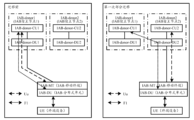
- the IAB-donor includes an IAB-donor-CU (central unit) and one or more IAB-donor-DU (distributed unit).
- the IAB-donor may include an IAB-donor-CU-CP, multiple IAB-donor-CU-UPs and multiple IAB-donor-DUs.
- the IAB-node is connected to the upstream IAB-node or IAB-donor-DU through the terminal function subset of the NR Uu interface (called the IAB-MT function in the IAB-node).
- the IAB-node provides wireless backhaul to the downstream IAB-node and terminal devices through the network function of the NR Uu interface (called the IAB-DU function of the IAB-node).
- the F1-C service between the IAB-node and the IAB-donor-CU is backhauled through the IAB-donor-DU and the optional intermediate hop IAB-node.
- the F1-U service between the IAB-node and the IAB-donor-CU is backhauled through the IAB-donor-DU and the optional intermediate hop IAB-node.
- the mobile IAB research work focuses on scenarios where vehicle-mounted mobile IAB nodes provide 5G coverage or capability enhancement for vehicle-mounted and/or surrounding terminal devices.
- mobile IAB can perform one or more partial migrations.
- the IAB-donor-CU connected to the IAB-node may change with the movement of the IAB-node, so it is necessary to perform the IAB-node migration process.
- There are two types of migration processes partial migration (only IAB-MT migrates, and IAB-DU remains on the source IAB-donor) and full migration (IAB-MT and IAB-DU migrate from the source IAB-donor to the same target IAB-donor).
- the migration process can also include other migrations besides the above two, such as IAB-DU migration.
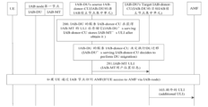
- Partial migration means that only the IAB-MT on the IAB-node migrates (also called switching) to a new IAB-donor, while the IAB-DU on the IAB-node still maintains the connection with the original IAB-donor (the connection needs to go through the IAB-donor-DU of the IAB-MT, that is, the corresponding transmission path needs to be established under the IAB-donor of the IAB-MT), and the terminal device context on the IAB-DU is also saved on the original IAB-donor.
- the switching is shown in Figure 9.
- the situation before the switching is shown in the left box in Figure 9. Before the migration, IAB-MT and IAB-DU are both connected to IAB-donor-CU1.
- IAB-donor-CU1 is the donor that originally serves IAB-node. After a partial migration, IAB-donor-CU1 can be called F1 terminating IAB-donor-CU (or IAB-donor-CU of IAB-DU). At this time, the data of the terminal device will be transmitted between IAB-donor-CU1 through the F1 connection (only the data routing will pass through IAB-donor-DU2), that is, the context of the terminal device is saved on the F1 terminating IAB-donor, and IAB-MT has been switched to IAB-donor-CU2. The data of IAB-MT is transmitted through IAB-donor-CU2. IAB-donor-CU2 is called non-F1 terminating IAB-donor (or IAB-donor-CU of IAB-MT).
- the F1-terminating IAB-donor (or IAB-DU's IAB-donor-CU) is IAB-donor-CU1
- the non-F1 terminating IAB-donor is IAB-donor-CU2 (or IAB-MT's IAB-donor-CU).
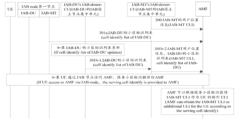
- IAB-MT may switch to a new IAB-donor (also called IAB-MT's target IAB-donor-CU), namely IAB-donor-CU3.
- IAB-donor-CU2 will notify IAB-donor-CU1: IAB-MT has switched to a new IAB-donor-CU, namely IAB-donor-CU3. If IAB-donor-CU1 decides to perform the IAB transport migration management process to IAB-donor-CU3 (i.e., perform another partial migration), all traffic between IAB-DU and IAB-donor-CU1 will be migrated from the path under IAB-donor-CU2 to the path under IAB-donor-CU3.
- the IAB-node provides wireless access and wireless backhaul for access services to terminal devices.
- the donor node (IAB-donor) provides wireless backhaul functions to the IAB-node and provides an interface between the terminal device and the core network device.
- the IAB-node is connected to the IAB-donor through a wireless backhaul link, so that the terminal device served by the IAB-node is connected to the core network device.
- a terminal device accesses the network through an IAB-node
- the relevant technology does not support the core network device connected to the terminal device to obtain the user location information of the IAB-node to assist the core network device of the terminal device in managing the location information of the terminal device. Therefore, how the core network device of the terminal device determines the user location information of the IAB-node is an urgent problem to be solved.
- Figure 11 is a flow chart of an information acquisition method provided by an embodiment of the present disclosure.
- the information acquisition method of the embodiment of the present disclosure can be executed by a core network device, or can also be executed by a network function in the core network device, for example, it can be executed by AMF.
- the method may include but is not limited to the following steps:
- S111 Receive first indication information sent by a first node or a second node, wherein the first node is a host node of the second node, and the first indication information is used to indicate user location information of the second node.
- the core network device receives the first indication information sent by the first node, and the first indication information is used to indicate the user location information of the second node. Therefore, the core network device can determine the user location information of the second node.
- the user location information of the second node may be the access network information where the second node resides, including but not limited to at least one of E-UTRA (Evolved-UMTS Terrestrial Radio Access) user location information, NR user location information, and information of a non-3GPP access network.
- E-UTRA Evolved-UMTS Terrestrial Radio Access
- the user location information of the second node may be the cell information where the second node resides, TAI (Tracking Area Identity), PSCell (Primary SCG (Secondary Cell Group) Cell) information, information used to identify a non-public network, and corresponding time information, for example: residing in a first cell at a first time, residing in a second cell at a second time, and so on.
- the residing cell may be information of a cell that has already resided, or information of a cell that will reside in the future.
- the user location information of the second node may also include the moving speed and/or movement trajectory of the second node.
- the core network device receives the first indication information sent by the first node or the second node, including: receiving an NGAP message sent by the first node, wherein the NGAP message includes the first indication information; or receiving an NAS message sent by the second node, wherein the NAS message includes the first indication information.
- the core network device receives the first indication information sent by the first node, and may receive a Next Generation Application Protocol (NGAP) message sent by the first node, wherein the NGAP message includes the first indication information.
- NGAP Next Generation Application Protocol
- the NGAP message is a UE-related message, including but not limited to an initial UE message, a UE context establishment feedback message, a UE context modification feedback message, a UE context release completion message, an RRC inactive transition report message, a PDU session resource release feedback message, a PDU session resource modification feedback message, a PDU resource notification message, and at least one of a PDU session resource modification indication message.
- the NGAP message includes user location information of the terminal device, and the user location information of the terminal device includes first indication information.
- the NGAP message includes user location information of the terminal device and first indication information.
- the core network device receives the first indication information sent by the second node, and may receive a non-access stratum (NAS) message sent by the second node, wherein the NAS message includes the first indication information.
- NAS non-access stratum
- the second node may be an IAB node (IAB-node), and the first node may be a donor node (IAB-donor) of the second node.
- IAB-node IAB node
- IAB-donor donor node
- the user location information of the second node is the user location information of the MT of the second node
- the first node is the host node of the MT of the second node
- the first node is the host node of the DU of the second node.
- the second node may include a mobile terminal (MT) part and a distributed unit (DU) part.
- MT mobile terminal
- DU distributed unit
- the user location information of the second node is the user location information of the MT of the second node.
- the second node may perform partial migration or full migration, and the MT (IAB-MT) and DU (IAB-DU) of the second node may be connected to the same host node, or may be connected to different host nodes respectively.
- the first node is a donor node (IAB-donor) of the second node.
- the first node may be a donor node of the MT of the second node, or may also be a donor node of the DU of the second node.
- the first node may be the host node of the MT and DU of the second node, and the embodiments of the present disclosure do not impose specific limitations on this.
- the first node may include an IAB-donor-CU (central unit) and one or more IAB-donor-DUs (distributed units).
- the first node may also be an IAB-donor-CU.
- the core network device receives the first indication information sent by the first node or the second node, and can receive the first indication information sent by the first node or the second node at any time, and the first indication information is used to indicate the user location information of the second node.
- the core network device may receive the first indication information sent by the first node or the second node through a non-terminal device related message, or the core network device may also receive the first indication information sent by the first node or the second node through a terminal device related message when the terminal device is connected to the core network device through the second node, and so on.
- each step can be independent, arbitrarily combined or exchanged in order, and the optional methods or optional examples can be arbitrarily combined and can be arbitrarily combined with other implementation modes or examples.
- the core network device receives the first indication information sent by the first node or the second node, wherein the first node is the host node of the second node, and the first indication information is used to indicate the user location information of the second node.
- the core network device can determine the user location information of the second node.
- Figure 12 is a flowchart of another information acquisition method provided by an embodiment of the present disclosure.
- the information acquisition method of the embodiment of the present disclosure can be executed by a core network device, or can also be executed by a network function in the core network device, for example, it can be executed by AMF.
- the method may include but is not limited to the following steps:
- S121 Receive first indication information sent by a first node or a second node, wherein the first node is a host node of the second node, and the first indication information is used to indicate user location information of the second node.
- S121 can refer to the relevant description in the above embodiment, and will not be repeated here.
- S122 Determine, based on the first indication information, that the additional user location information of the terminal device is the user location information of the second node, wherein a network connection is provided for the terminal device through the second node.
- the terminal device can be connected to the core network device through the base station, and the base station can send the user location information (ULI) of the terminal device to the core network device.
- the core network device can decide whether to allow the terminal device to perform specific operations at the location based on the user location information and provide services for the terminal device.
- ULI is, for example, but not limited to, a cell identifier (Cell ID) and a tracking area identifier (TAI).
- Cell ID cell identifier
- TAI tracking area identifier
- the terminal device is connected to the core network device through an IAB-node. Considering that the IAB-node is movable, the core network device needs to consider the user location information of the IAB-node when providing services to the terminal device.
- the core network device when the core network device determines to provide a network connection for the terminal device through the second node, it can determine, according to the first indication information, that the additional user location information of the terminal device is the user location information of the second node. Thus, the core network device can consider the user location information of the second node as the additional user location information of the terminal device to provide accurate services to the terminal device and improve the service quality.
- the core network device determines to provide a network connection for the terminal device through the second node. Upon receiving first indication information sent by the first node or the second node when the terminal device is connected to the core network device through the second node, the core network device determines to provide a network connection for the terminal device through the second node.
- each step can be independent, arbitrarily combined or exchanged in order, and the optional methods or optional examples can be arbitrarily combined and can be arbitrarily combined with other implementation modes or examples.
- S121 to S122 can be implemented separately or in combination with any other steps in the embodiments of the present disclosure, for example, in combination with S111 in the embodiments of the present disclosure, and the embodiments of the present disclosure are not limited to this.
- the core network device receives the first indication information sent by the first node or the second node, wherein the first node is the host node of the second node, and the first indication information is used to indicate the user location information of the second node; according to the first indication information, the additional user location information of the terminal device is determined to be the user location information of the second node, wherein the network connection is provided for the terminal device through the second node.
- the core network device can provide accurate services for the terminal device according to the user location information and the additional user location information of the terminal device to improve the service quality.
- Figure 13a is a flowchart of another information acquisition method provided by an embodiment of the present disclosure.
- the information acquisition method of the embodiment of the present disclosure can be executed by a core network device, or can also be executed by a network function in the core network device, for example, it can be executed by AMF.
- the method may include but is not limited to the following steps:
- S131a Receive first indication information sent by a first node or a second node, wherein the first node is a host node of the second node, and the first indication information is used to indicate user location information of the second node.
- S131a can refer to the relevant description in the above embodiment, which will not be repeated here.
- S132a Receive second indication information sent by the first node or the second node, where the second indication information is used to indicate a cell identifier list under the second node.
- S133a Determine, according to the cell identifier list of the second node and the user location information of the second node, an association relationship between the user location information of the second node and the cell identifier list of the second node.
- S134a Determine additional user location information of the terminal device according to the service cell identifier and association relationship of the terminal device.
- a core network device receives second indication information sent by a first node or a second node, and the second indication information indicates a cell identifier list under the second node.
- the core network device can determine the cell identifier list under the second node.
- the core network device receives the second indication information sent by the first node or the second node, including: receiving an NGAP message sent by the first node, wherein the NGAP message includes the second indication information; or receiving a NAS message sent by the second node, wherein the NAS message includes the second indication information.
- the core network device receives the second indication information sent by the first node, and may receive an NGAP message sent by the first node, wherein the NGAP message includes the second indication information.
- the core network device receives the second indication information sent by the second node, and may receive a NAS message sent by the second node, wherein the NAS message includes the second indication information.
- the core network device receives the second indication information sent by the first node or the second node, and can determine the association between the user location information of the second node and the cell identification list under the second node based on the cell identification list under the second node in the second indication information and the user location information of the second node.
- the core network device can determine the additional user location information of the terminal device according to the serving cell identifier and the association relationship of the terminal device.
- the core network device can consider the user location information of the second node as the additional user location information of the terminal device, and provide accurate services for the terminal device to improve the service quality.
- the core network device determines the association relationship between the user location information of the second node and the cell identification list under the second node.
- the additional user location information of the terminal device can be determined to be the user location information of the second node. Therefore, the core network device can consider the user location information of the second node as the additional user location information of the terminal device to provide accurate services for the terminal device and improve the service quality.
- each step can be independent, arbitrarily combined or exchanged in order, and the optional methods or optional examples can be arbitrarily combined and can be arbitrarily combined with other implementation modes or examples.
- S131 to S134 can be implemented separately or in combination with any other steps in the embodiments of the present disclosure, for example, in combination with S111 in the embodiments of the present disclosure, and the embodiments of the present disclosure are not limited to this.
- the core network device receives the first indication information sent by the first node or the second node, wherein the first node is the host node of the second node, and the first indication information is used to indicate the user location information of the second node; receives the second indication information sent by the first node or the second node, wherein the second indication information is used to indicate the cell identification list under the second node; determines the association relationship between the user location information of the second node and the cell identification list according to the cell identification list under the second node and the user location information of the second node, and determines the additional user location information of the terminal device according to the service cell identification and the association relationship of the terminal device.
- the core network device can consider the user location information of the second node as the additional user location information of the terminal device, so as to provide accurate services for the terminal device and improve the service quality.
- Figure 13b is a flowchart of another information acquisition method provided by an embodiment of the present disclosure.
- the information acquisition method of the embodiment of the present disclosure can be executed by a core network device, or can also be executed by a network function in the core network device, for example, it can be executed by AMF.
- the method may include but is not limited to the following steps:
- S131b Receive first indication information sent by the first node or the second node, wherein the first node is a host node of the second node, and the first indication information is used to indicate user location information of the second node.
- S131b can refer to the relevant description in the above embodiment, which will not be repeated here.
- S132b Receive second indication information sent by the first node or the second node, where the second indication information is used to indicate an identifier of the second node.
- the identifier of the second node is used to identify the second node or the MT on the second node, and the identifier of the second node can be AMF UE NGAP ID, RAN UE NGAP ID, UE XnAP ID, F1AP UE ID, or GPSI (Generic Public Subscription Identifier), etc.
- S133b Determine, according to the identifier of the second node and the user location information of the second node, an association relationship between the user location information of the second node and the identifier of the second node.
- S134b Determine additional user location information of the terminal device according to the second node identifier and the association relationship provided by the terminal device.
- the core network device receives second indication information sent by the first node or the second node, and the second indication information indicates the identifier of the second node.
- the core network device can determine the identifier of the second node.
- the core network device receives the second indication information sent by the first node or the second node, including: receiving an NGAP message sent by the first node, wherein the NGAP message includes the second indication information; or receiving a NAS message sent by the second node, wherein the NAS message includes the second indication information.
- the core network device receives the second indication information sent by the first node, and may receive an NGAP message sent by the first node, wherein the NGAP message includes the second indication information.
- the core network device receives the second indication information sent by the second node, and may receive a NAS message sent by the second node, wherein the NAS message includes the second indication information.
- the core network device receives the second indication information sent by the first node or the second node, and can determine the association between the user location information of the second node and the identifier of the second node based on the identifier of the second node in the second indication information and the user location information of the second node.
- the core network device can determine the additional user location information of the terminal device according to the identifier and association relationship of the second node provided by the terminal device.
- the core network device can consider the user location information of the second node as the additional user location information of the terminal device, and provide accurate services for the terminal device to improve the service quality.
- the core network device determines the association between the user location information of the second node and the identifier of the second node, and when the terminal device provides the identifier of the second node, the additional user location information of the terminal device can be determined as the user location information of the second node.
- the core network device can consider the user location information of the second node as the additional user location information of the terminal device to provide accurate services for the terminal device and improve the service quality.
- each step can be independent, arbitrarily combined or exchanged in order, and the optional methods or optional examples can be arbitrarily combined and can be arbitrarily combined with other implementation modes or examples.
- S131 to S134 can be implemented separately or in combination with any other steps in the embodiments of the present disclosure, for example, in combination with S111 in the embodiments of the present disclosure, and the embodiments of the present disclosure are not limited to this.
- the core network device receives the first indication information sent by the first node or the second node, wherein the first node is the host node of the second node, and the first indication information is used to indicate the user location information of the second node; receives the second indication information sent by the first node or the second node, wherein the second indication information is used to indicate the identifier of the second node; determines the association relationship between the user location information of the second node and the identifier of the second node according to the identifier of the second node and the user location information of the second node; determines the additional user location information of the terminal device according to the identifier and the association relationship of the second node provided by the terminal device.
- the core network device can consider the user location information of the second node as the additional user location information of the terminal device, so as to provide accurate services for the terminal device and improve the service quality.
- Figure 14a is a flowchart of another information acquisition method provided by an embodiment of the present disclosure.
- the information acquisition method of the embodiment of the present disclosure can be executed by a core network device, or can also be executed by a network function in the core network device, for example, it can be executed by AMF.
- the method may include but is not limited to the following steps:
- S141a Receive first indication information sent by a first node or a second node, wherein the first node is a host node of the second node, and the first indication information is used to indicate user location information of the second node.
- S141a can refer to the relevant description in the above embodiment, which will not be repeated here.
- S142a Receive second indication information sent by the first node or the second node, where the second indication information is used to indicate an association relationship between a cell identifier list under the second node and user location information of the second node.
- S143a Determine additional user location information of the terminal device according to the service cell identifier and association relationship of the terminal device.
- a core network device receives second indication information sent by a first node or a second node, and the second indication information indicates an association between a cell identification list under the second node and user location information of the second node.
- the core network device can determine the association between the cell identification list under the second node and the user location information of the second node.
- the core network device can determine the additional user location information of the terminal device according to the serving cell identifier and the association relationship of the terminal device.
- the core network device can consider the user location information of the second node as the additional user location information of the terminal device, and provide accurate services for the terminal device to improve the service quality.
- the core network device determines the association relationship between the user location information of the second node and the cell identification list under the second node.
- the additional user location information of the terminal device can be determined to be the user location information of the second node. Therefore, the core network device can consider the user location information of the second node as the additional user location information of the terminal device to provide accurate services for the terminal device and improve the service quality.
- the core network device receives the second indication information sent by the first node or the second node, including: receiving an NGAP message sent by the first node, wherein the NGAP message includes the second indication information; or receiving a NAS message sent by the second node, wherein the NAS message includes the second indication information.
- the core network device receives the second indication information sent by the first node, and may receive an NGAP message sent by the first node, wherein the NGAP message includes the second indication information.
- the core network device receives the second indication information sent by the second node, and may receive a NAS message sent by the second node, wherein the NAS message includes the second indication information.
- each step can be independent, arbitrarily combined or exchanged in order, and the optional methods or optional examples can be arbitrarily combined and can be arbitrarily combined with other implementation modes or examples.
- S141 to S143 can be implemented separately or in combination with any other steps in the embodiments of the present disclosure, for example, in combination with S111 in the embodiments of the present disclosure, and the embodiments of the present disclosure are not limited to this.
- the core network device receives the first indication information sent by the first node or the second node, wherein the first node is the host node of the second node, and the first indication information is used to indicate the user location information of the second node; receives the second indication information sent by the first node or the second node, wherein the second indication information is used to indicate the association relationship between the cell identification list under the second node and the user location information of the second node; determines the additional user location information of the terminal device according to the service cell identification and the association relationship of the terminal device.
- the core network device can consider the user location information of the second node as the additional user location information of the terminal device, so as to provide accurate services for the terminal device and improve the service quality.
- Figure 14b is a flowchart of another information acquisition method provided by an embodiment of the present disclosure.
- the information acquisition method of the embodiment of the present disclosure can be executed by a core network device, or can also be executed by a network function in the core network device, for example, it can be executed by an AMF.
- the method may include but is not limited to the following steps:
- S141b Receive first indication information sent by the first node or the second node, wherein the first node is a host node of the second node, and the first indication information is used to indicate user location information of the second node.
- S141b can refer to the relevant description in the above embodiment, which will not be repeated here.
- S142b Receive second indication information sent by the first node or the second node, where the second indication information is used to indicate an association relationship between an identifier of the second node and user location information of the second node.
- S143b Determine additional user location information of the terminal device according to the identifier and association relationship of the second node provided by the terminal device.
- a core network device receives second indication information sent by a first node or a second node, and the second indication information indicates an association between an identifier of the second node and user location information of the second node.
- the core network device can determine the association between the identifier of the second node and the user location information of the second node.
- the core network device can determine the additional user location information of the terminal device according to the provided identifier and association relationship of the second node.
- the core network device can consider the user location information of the second node as the additional user location information of the terminal device, and provide accurate services for the terminal device to improve the service quality.
- the core network device determines the association between the user location information of the second node and the identifier of the second node, and when the terminal device provides the identifier of the second node, the additional user location information of the terminal device can be determined as the user location information of the second node.
- the core network device can consider the user location information of the second node as the additional user location information of the terminal device to provide accurate services for the terminal device and improve the service quality.
- the identifier of the second node is used to identify the second node or the MT on the second node, and the identifier of the second node can be AMF UE NGAP ID, RAN UE NGAP ID, UE XnAP ID, F1AP UE ID, or GPSI (Generic Public Subscription Identifier), etc.
- the core network device receives the second indication information sent by the first node or the second node, including: receiving an NGAP message sent by the first node, wherein the NGAP message includes the second indication information; or receiving a NAS message sent by the second node, wherein the NAS message includes the second indication information.
- the core network device receives the second indication information sent by the first node, and may receive an NGAP message sent by the first node, wherein the NGAP message includes the second indication information.
- the core network device receives the second indication information sent by the second node, and may receive a NAS message sent by the second node, wherein the NAS message includes the second indication information.
- each step can be independent, arbitrarily combined or exchanged in order, and the optional methods or optional examples can be arbitrarily combined and can be arbitrarily combined with other implementation modes or examples.
- S141 to S143 can be implemented separately or in combination with any other steps in the embodiments of the present disclosure, for example, in combination with S111 in the embodiments of the present disclosure, and the embodiments of the present disclosure are not limited to this.
- the core network device receives the first indication information sent by the first node or the second node, wherein the first node is the host node of the second node, and the first indication information is used to indicate the user location information of the second node; receives the second indication information sent by the first node or the second node, wherein the second indication information is used to indicate the association relationship between the identifier of the second node and the user location information of the second node; and determines the additional user location information of the terminal device according to the identifier and the association relationship of the second node provided by the terminal device.
- the core network device can consider the user location information of the second node as the additional user location information of the terminal device, so as to provide accurate services for the terminal device and improve the service quality.
- Figure 15 is a flowchart of another information acquisition method provided by an embodiment of the present disclosure. It should be noted that the information acquisition method of the embodiment of the present disclosure can be executed by the first node. As shown in Figure 15, the method may include but is not limited to the following steps:
- S151 Send first indication information to a core network device, wherein the first node is a host node of a second node, and the first indication information is used to indicate user location information of the second node.
- the first node may send first indication information to the core network device, the first indication information being used to indicate the user location information of the second node.
- the core network device supporting the connection of the terminal device obtains the user location information of the second node, wherein the terminal device accesses the network through the second node.
- the user location information of the second node may be the access network information where the second node resides, including but not limited to E-UTRA (Evolved-UMTS Terrestrial Radio Access) user location information, NR user location information, and access information of a non-3GPP network.
- E-UTRA Evolved-UMTS Terrestrial Radio Access
- the user location information of the second node may be the cell information where the second node resides, TAI (Tracking Area Identity), PSCell (Primary SCG (Secondary Cell Group) Cell) information, information used to identify a non-public network, and corresponding time information, for example: residing in a first cell at a first time, residing in a second cell at a second time, and so on.
- the resident cell may be information of a cell that has already resided, or information of a cell that will reside in the future.
- the user location information of the second node may also include the moving speed and/or movement trajectory of the second node.
- the first node sends the first indication information to the core network device, including: sending a NGAP message to the core network device, wherein the NGAP message includes the first indication information.
- the NGAP message is a UE-related message, including but not limited to an initial UE message, a UE context establishment feedback message, a UE context modification feedback message, a UE context release completion message, an RRC inactive transition report message, a PDU session resource release feedback message, a PDU session resource modification feedback message, a PDU resource notification message, and at least one of a PDU session resource modification indication message.
- the NGAP message includes user location information of the terminal device, and the user location information of the terminal device includes first indication information.
- the NGAP message includes user location information of the terminal device and first indication information.
- the first node sends the first indication information to the core network device, and may send an NGAP message to the core network device, wherein the NGAP message includes the first indication information.
- the user location information of the second node is the user location information of the MT of the second node
- the first node is the host node of the MT of the second node
- the first node is the host node of the DU of the second node.
- the second node may include a mobile terminal (mobile termination, MT) part and a distributed unit (distributed unit, DU) part.
- MT mobile terminal
- DU distributed unit
- the user location information of the second node is the user location information of the MT of the second node.
- the second node may perform partial migration or full migration, and the MT (IAB-MT) and DU (IAB-DU) of the second node may be connected to the same host node, or may be connected to different host nodes respectively.
- the first node is a donor node (IAB-donor) of the second node.
- the first node may be a donor node of the MT of the second node, or may also be a donor node of the DU of the second node.
- the first node may be the host node of the MT and DU of the second node, and the embodiments of the present disclosure do not impose specific limitations on this.
- the first node may include an IAB-donor-CU (central unit) and one or more IAB-donor-DUs (distributed units).
- the first node may also be an IAB-donor-CU.
- the first node sends the first indication information to the core network device, and the first indication information may be sent to the core network device at any time.
- the first indication information is used to indicate the user location information of the second node.
- the first node may send the first indication information to the core network device when there is no terminal device connected to the core network device through the second node, or the first node may also send the first indication information to the core network device when the terminal device is connected to the core network device through the second node, and so on.
- each step can be independent, arbitrarily combined or exchanged in order, and the optional methods or optional examples can be arbitrarily combined and can be arbitrarily combined with other implementation modes or examples.
- the first node sends the first indication information to the core network device, wherein the first node is the host node of the second node, and the first indication information is used to indicate the user location information of the second node.
- the core network device supporting the connection of the terminal device obtains the user location information of the second node, wherein the terminal device accesses the network through the second node.
- Figure 16 is a flowchart of another information acquisition method provided by an embodiment of the present disclosure. It should be noted that the information acquisition method of the embodiment of the present disclosure can be executed by the first node. As shown in Figure 16, the method may include but is not limited to the following steps:
- S161 Send first indication information to a core network device, wherein the first node is a host node of a second node, and the first indication information is used to indicate user location information of the second node.
- S162 Send second indication information to the core network device.
- the second indication information is used to indicate at least one of the following:
- the first node may send second indication information to the core network device, where the second indication information is used to indicate the cell identifier list of the second node, thereby supporting the first node to report the cell identifier list of the second node to the core network device.
- the first node may send second indication information to the core network device, where the second indication information is used to indicate the identifier of the second node, thereby supporting the first node to report the identifier of the second node to the core network device.
- the first node may send second indication information to the core network device, and the second indication information is used to indicate the association relationship between the cell identification list under the second node and the user location information of the second node.
- the first node may support reporting the association relationship between the cell identification list under the second node and the user location information of the second node to the core network device.
- the first node may send second indication information to the core network device, and the second indication information is used to indicate the association relationship between the identifier of the second node and the user location information of the second node.
- the first node may support reporting the association relationship between the identifier of the second node and the user location information of the second node to the core network device.
- the identifier of the second node is used to identify the second node or the MT on the second node, and the identifier of the second node can be AMF UE NGAP ID, RAN UE NGAP ID, UE XnAP ID, F1AP UE ID, or GPSI (Generic Public Subscription Identifier), etc.
- the first node sends the second indication information to the core network device, including: sending a NGAP message to the core network device, wherein the NGAP message includes the second indication information.
- the first node sends the second indication information to the core network device, and may send an NGAP message to the core network device, wherein the NGAP message includes the second indication information.
- each step can be independent, arbitrarily combined or exchanged in order, and the optional methods or optional examples can be arbitrarily combined and can be arbitrarily combined with other implementation modes or examples.
- S161 to S162 can be implemented separately or in combination with any other steps in the embodiments of the present disclosure, for example, in combination with S151 in the embodiments of the present disclosure, and the embodiments of the present disclosure are not limited to this.
- the first node sends a first indication message to the core network device, wherein the first node is the host node of the second node, and the first indication message is used to indicate the user location information of the second node; and sends a second indication message to the core network device.
- the first node is supported to report the user location information of the second node, and at least one of the cell identification list under the second node, the identification of the second node, the association relationship between the cell identification list under the second node and the user location information of the second node, and the association relationship between the identification of the second node and the user location information of the second node to the core network device.
- Figure 17 is a flowchart of another information acquisition method provided by an embodiment of the present disclosure. It should be noted that the information acquisition method of the embodiment of the present disclosure can be executed by the first node. As shown in Figure 17, the method may include but is not limited to the following steps:
- S171 Determine user location information of the second node.
- the first node may determine the user location information of the second node.
- the first node can determine the user location information of the second node by itself, thereby determining the user location information of the second node, or can also receive the user location information of the second node sent by the second node, thereby determining the user location information of the second node, or can also receive the user location information of the second node sent by other nodes, thereby determining the user location information of the second node, and so on.
- the embodiments of the present disclosure do not impose specific restrictions on this.
- S172 Send first indication information to the core network device, wherein the first node is a host node of the second node, and the first indication information is used to indicate user location information of the second node.
- each step can be independent, arbitrarily combined or exchanged in order, and the optional methods or optional examples can be arbitrarily combined and can be arbitrarily combined with other implementation modes or examples.
- S171 to S172 can be implemented separately or in combination with any other steps in the embodiments of the present disclosure, for example, in combination with S151 and/or S161 to S162 in the embodiments of the present disclosure, and the embodiments of the present disclosure are not limited to this.
- the first node sends the first indication information to the core network device, wherein the first node is the host node of the second node, and the first indication information is used to indicate the user location information of the second node.
- the core network device supporting the connection of the terminal device obtains the user location information of the second node, wherein the terminal device accesses the network through the second node.
- Figure 18 is a flowchart of another information acquisition method provided by an embodiment of the present disclosure. It should be noted that the information acquisition method of the embodiment of the present disclosure can be executed by the first node. As shown in Figure 18, the method may include but is not limited to the following steps:
- S181 Receive a first message sent by a third node, where the first message is used to indicate user location information of a second node.
- S182 Determine user location information of the second node according to the first message.
- a first node may receive a first message sent by a third node, wherein the first message is used to indicate user location information of a second node.
- the first node may determine user location information of the second node based on the user location information indicating the second node in the first message.
- the first message can be used to indicate the user location information of the second node, but the first message is not limited to being used for other purposes, for example, it can also be used to indicate other information, and the embodiment of the present disclosure does not impose specific limitations on this.
- the third node is a DU of the second node.
- the third node is the DU of the second node.
- the host node of the DU of the second node receives the first message sent by the DU of the second node, wherein the first message is used to indicate the user location information of the second node, and the host node of the DU of the second node can determine the user location information of the second node based on the user location information used to indicate the second node in the first message.
- the third node is a host node for a MT of the second node.
- the third node is the host node of the MT of the second node.
- the host node of the DU of the second node receives a first message sent by the host node of the MT of the second node, wherein the first message includes user location information indicating the second node, and the host node of the DU of the second node can determine the user location information of the second node based on the user location information of the second node in the first message.
- the host node of the DU of the second node when the DU of the second node migrates, and the DU of the second node migrates from the source host node to the target host node, the host node of the DU of the second node can be the source host node of the DU of the second node or the target host node of the DU of the second node.
- the third node is the source host node of the DU of the second node.
- the third node is the source host node of the DU of the second node.
- the target host node of the DU of the second node receives a first message sent by the source host node of the DU of the second node, wherein the first message includes user location information indicating the second node, and the target host node of the DU of the second node can determine the user location information of the second node based on the user location information indicating the second node in the first message.
- a first node determines user location information of a second node, including: saving the user location information of the second node, and determining an association between the user location information of the second node and the second node; if a terminal device accesses a core network device through the second node, the first node sends the user location information of the second node to the core network device through a message related to the terminal device.
- the first message is at least one of the following:
- the first message may be an F1 application protocol (F1 application protocol, F1AP) message.
- F1 application protocol F1 application protocol, F1AP
- the first message may be a radio resource control (RRC) message.
- RRC radio resource control
- the first message may be an Xn interface application protocol (Xn application protocol, XnAP) message.
- Xn application protocol XnAP
- the first message is a message for instructing the MT of the second node to perform handover.
- the first message may be a message for instructing the MT of the second node to perform a handover.
- the first message may be a message for notifying the IAB-MT of the handover.
- the first message is a message related to the terminal device or a message unrelated to the terminal device.
- the first message may be a message related to the terminal device, or the first message may also be a message unrelated to the terminal device.
- the first message when the first message is a message unrelated to the terminal device, the first message also includes a cell identifier list and/or an identifier of the second node.
- the first message when the first message is a message unrelated to the terminal device, the first message may further include a cell identifier list and/or an identifier of the second node.
- the first message when the first message is an F1AP message, the first message is used to indicate user location information of the second node, and the user location information of the second node may be included in messages such as an F1 setup request (F1 SETUP REQUEST) message and/or a GNB-DU configuration update (GNB-DU CONFIGURATION UPDATE) message.
- F1 setup request F1 SETUP REQUEST
- GNB-DU CONFIGURATION UPDATE GNB-DU CONFIGURATION UPDATE
- the first message when the first message is an F1AP message, the first message is used to indicate user location information of the second node, and the user location information of the second node may be included in a served cell information IE (served cell information IE).
- a served cell information IE serving cell information IE
- the F1AP message may be at least one of the following:
- Terminal equipment context establishment feedback (UE CONTEXT SETUP RESPONSE) message
- Terminal equipment context modification feedback (UE CONTEXT MODIFICATION RESPONSE) message
- Terminal equipment inactivation notification (UE INACTIVITY NOTIFICATION) message.
- the first message when the first message is an XnAP, the first message is used to indicate user location information of the second node, and the first message may be an IAB-MT migration completion indication message.
- each step can be independent, arbitrarily combined or exchanged in order, and the optional methods or optional examples can be arbitrarily combined and can be arbitrarily combined with other implementation modes or examples.
- S181 to S182 can be implemented separately or in combination with any other steps in the embodiments of the present disclosure, for example, in combination with S151 and/or S161 to S162 and/or S171 to S172 in the embodiments of the present disclosure, and the embodiments of the present disclosure are not limited to this.
- the first node receives the first message sent by the third node, wherein the first message is used to indicate the user location information of the second node; the user location information of the second node is determined according to the first message.
- the first node can determine the user location information of the second node.
- Figure 19 is a flowchart of another information acquisition method provided by an embodiment of the present disclosure. It should be noted that the information acquisition method of the embodiment of the present disclosure can be executed by the first node. As shown in Figure 19, the method may include but is not limited to the following steps:
- S191 Determine an association relationship between a cell identifier list of a second cell and user location information of a second node, or determine an association relationship between an identifier of a second node and user location information of the second node.
- the first node can determine the cell identification list of the second cell and the user location information of the second node by itself, and then establish an association relationship between the cell identification list and the user location information of the second node, thereby determining the association relationship between the cell identification list of the second cell and the user location information of the second node.
- the first node can also receive the association relationship between the cell identification list and the user location information of the second node sent by other nodes, thereby determining the association relationship between the cell identification list of the second cell and the user location information of the second node.
- the first node can determine the identifier of the second node and the user location information of the second node by itself, and then establish an association relationship between the identifier of the second node and the user location information of the second node, thereby determining the association relationship between the identifier of the second node and the user location information of the second node.
- the first node can also receive the association relationship between the identifier of the second node and the user location information of the second node sent by other nodes, thereby determining the association relationship between the identifier of the second node and the user location information of the second node.
- each step can be independent, arbitrarily combined or exchanged in order, and the optional methods or optional examples can be arbitrarily combined and can be arbitrarily combined with other implementation modes or examples.
- S191 can be implemented alone or in combination with any other steps in the embodiments of the present disclosure, for example, in combination with S151 and/or S161 to S162 and/or S171 to S172 and/or S181 to S182 in the embodiments of the present disclosure, and the embodiments of the present disclosure are not limited to this.
- the first node determines the association between the cell identifier list of the second cell and the user location information of the second node.
- the first node can determine the association between the cell identifier list of the second cell and the user location information of the second node.
- Figure 20 is a flowchart of another information acquisition method provided by an embodiment of the present disclosure. It should be noted that the information acquisition method of the embodiment of the present disclosure can be executed by a third node. As shown in Figure 20, the method may include but is not limited to the following steps:
- S201 Send a first message to a first node, where the first message is used to indicate user location information of a second node, and the first node is a host node of the second node.
- the third node may send a first message to the first node, wherein the first message is used to indicate the user location information of the second node, thereby supporting the third node to send the user location information of the second node to the first node.
- the first message can be used to indicate the user location information of the second node, but the first message is not limited to being used for other purposes, for example, it can also be used to indicate other information, and the embodiment of the present disclosure does not impose specific limitations on this.
- the third node is a DU of the second node.
- the third node is the DU of the second node.
- the DU of the second node may send a first message to the host node of the DU of the second node, where the first message is used to indicate the user location information of the second node.
- the third node is a host node for a MT of the second node.
- the third node is the host node of the MT of the second node.
- the host node of the MT of the second node may send a first message to the host node of the DU of the second node, where the first message is used to indicate the user location information of the second node.
- the host node of the DU of the second node when the DU of the second node migrates, and the DU of the second node migrates from the source host node to the target host node, the host node of the DU of the second node can be the source host node of the DU of the second node or the target host node of the DU of the second node.
- the third node is the source host node of the DU of the second node.
- the third node is the source host node of the DU of the second node.
- the source host node of the DU of the second node can send a first message to the target host node of the DU of the second node, and the first message is used to indicate the user location information of the second node.
- the first message is at least one of the following:
- the first message may be an F1 application protocol (F1 application protocol, F1AP) message.
- F1 application protocol F1 application protocol, F1AP
- the first message may be a radio resource control (RRC) message.
- RRC radio resource control
- the first message may be an Xn interface application protocol (Xn application protocol, XnAP) message.
- Xn application protocol XnAP
- the first message is a message for instructing the MT of the second node to perform handover.
- the first message may be a message for instructing the MT of the second node to perform a handover.
- the first message may be a message for notifying the IAB-MT of the handover.
- the first message is a message related to the terminal device or a message unrelated to the terminal device.
- the first message may be a message related to the terminal device, or the first message may also be a message unrelated to the terminal device.
- the first message when the first message is a message unrelated to the terminal device, the first message also includes a cell identifier list and/or an identifier of the second node.
- the first message when the first message is a message unrelated to the terminal device, the first message may further include a cell identifier list and/or an identifier of the second node.
- the first message also includes a cell identifier list.
- the first message when the first message is an F1AP message, the first message is used to indicate user location information of the second node, and the user location information of the second node may be included in messages such as an F1 setup request (F1 SETUP REQUEST) message and/or a GNB-DU configuration update (GNB-DU CONFIGURATION UPDATE) message.
- F1 setup request F1 SETUP REQUEST
- GNB-DU CONFIGURATION UPDATE GNB-DU CONFIGURATION UPDATE
- the first message when the first message is an F1AP message, the first message is used to indicate user location information of the second node, and the user location information of the second node may be included in a served cell information IE (served cell information IE).
- a served cell information IE serving cell information IE
- the F1AP message may be at least one of the following:
- Terminal equipment context establishment feedback (UE CONTEXT SETUP RESPONSE) message
- Terminal equipment context modification feedback (UE CONTEXT MODIFICATION RESPONSE) message
- Terminal equipment inactivation notification (UE INACTIVITY NOTIFICATION) message.
- the first message when the first message is an XnAP, the first message is used to indicate user location information of the second node, and the first message may be an IAB-MT migration completion indication message.
- each step can be independent, arbitrarily combined or exchanged in order, and the optional methods or optional examples can be arbitrarily combined and can be arbitrarily combined with other implementation modes or examples.
- the third node sends a first message to the first node, wherein the first message is used to indicate the user location information of the second node, and the first node is the host node of the second node.
- the third node is supported to send the user location information of the second node to the first node.
- Figure 21 is a flowchart of another information acquisition method provided by an embodiment of the present disclosure. It should be noted that the information acquisition method of the embodiment of the present disclosure can be executed by the second node. As shown in Figure 21, the method may include but is not limited to the following steps:
- S211 Send first indication information to the core network device, where the first indication information is used to indicate user location information of the second node.
- the second node may be an IAB-node, and the second node may send first indication information to the core network device, where the first indication information is used to indicate the user location information of the second node.
- the second node is supported to report the user location information of the second node to the core network device.
- the user location information of the second node may be the access network information where the second node resides, including but not limited to at least one of E-UTRA (Evolved-UMTS Terrestrial Radio Access) user location information, NR user location information, and information of a non-3GPP access network.
- E-UTRA Evolved-UMTS Terrestrial Radio Access
- the user location information of the second node may be the cell information where the second node resides, TAI (Tracking Area Identity), PSCell (Primary SCG (Secondary Cell Group) Cell) information, information used to identify a non-public network, and corresponding time information, for example: residing in a first cell at a first time, residing in a second cell at a second time, and so on.
- the resident cell may be information of a cell that has already resided, or information of a cell that will reside in the future.
- the user location information of the second node may also include the moving speed and/or movement trajectory of the second node.
- the second node sends the first indication information to the core network device, including: sending a NGAP message to the core network device, wherein the NGAP message includes the first indication information.
- the second node sends the first indication information to the core network device, and may send an NGAP message to the core network device, wherein the NGAP message includes the first indication information.
- the NGAP message is a UE-related message, including but not limited to an initial UE message, a UE context establishment feedback message, a UE context modification feedback message, a UE context release completion message, an RRC inactive transition report message, a PDU session resource release feedback message, a PDU session resource modification feedback message, a PDU resource notification message, and at least one of a PDU session resource modification indication message.
- the NGAP message includes user location information of the terminal device, and the user location information of the terminal device includes first indication information.
- the NGAP message includes user location information of the terminal device and first indication information.
- the user location information of the second node is user location information of the MT of the second node.
- the second node may include a mobile terminal (mobile termination, MT) part and a distributed unit (distributed unit, DU) part.
- MT mobile terminal
- DU distributed unit
- the user location information of the second node is the user location information of the MT of the second node.
- each step can be independent, arbitrarily combined or exchanged in order, and the optional methods or optional examples can be arbitrarily combined and can be arbitrarily combined with other implementation modes or examples.
- the second node sends first indication information to the core network device, wherein the first indication information is used to indicate the user location information of the second node, thereby supporting the second node to report the user location information of the second node to the core network device.
- Figure 22 is a flowchart of another information acquisition method provided by an embodiment of the present disclosure. It should be noted that the information acquisition method of the embodiment of the present disclosure can be executed by the second node. As shown in Figure 22, the method may include but is not limited to the following steps:
- S221 Send first indication information to the core network device, where the first indication information is used to indicate user location information of the second node.
- S222 Send second indication information to the core network device, where the second indication information is used to indicate a cell identifier list under the second node and/or an identifier of the second node.
- the second node may send second indication information to the core network device, the second indication information being used to indicate the cell identification list under the second node and/or the identification of the second node.
- the second node supports reporting the cell identification list to the core network device.
- the identifier of the second node is used to identify the second node or the MT on the second node, and the identifier of the second node can be AMF UE NGAP ID, RAN UE NGAP ID, UE XnAP ID, F1AP UE ID, or GPSI (Generic Public Subscription Identifier), etc.
- the second node sends the second indication information to the core network device, including: sending a NGAP message to the core network device, wherein the NGAP message includes the second indication information.
- the second node sends the second indication information to the core network device, and may send an NGAP message to the core network device, wherein the NGAP message includes the second indication information.
- each step can be independent, arbitrarily combined or exchanged in order, and the optional methods or optional examples can be arbitrarily combined and can be arbitrarily combined with other implementation modes or examples.
- S221 to S222 can be implemented separately or in combination with any other steps in the embodiments of the present disclosure, for example, in combination with S211 in the embodiments of the present disclosure, and the embodiments of the present disclosure are not limited to this.
- the second node sends first indication information to the core network device, wherein the first indication information is used to indicate the user location information of the second node, and sends second indication information to the core network device, wherein the second indication information is used to indicate the cell identification list under the second node and/or the identification of the second node.
- the second node is supported to report the user location information of the second node and the cell identification list to the core network device.
- Figure 23 is a structural diagram of an information acquisition system provided by an embodiment of the present disclosure. As shown in Figure 23, the system may include but is not limited to:
- the core network device is configured to receive first indication information sent by a first node or a second node, wherein the first node is a host node of the second node, and the first indication information is used to indicate user location information of the second node.
- the first node or the second node is configured to send first indication information to a core network device, wherein the first node is a host node of the second node, and the first indication information is used to indicate user location information of the second node.
- the system may further include a third node configured to send a first message to the first node, wherein the first message is used to indicate user location information of the second node, and the first node is a host node of the second node;
- the first node is further configured to determine user location information of the second node according to the first message.
- the mobile IAB research work focuses on the scenarios where the vehicle-mounted mobile IAB nodes provide 5G coverage/capability enhancement for vehicle-mounted and/or surrounding terminals.
- the base station serving the UE can send user location information (ULI) to the AMF through signaling, and the AMF can decide whether to allow the terminal to operate at its current location based on the user location information.
- UMI user location information
- 3GPP SA2 agrees that the IAB-donor serving the UE needs to provide the ULI of the IAB-MT of the IAB-node as an additional ULI.
- the IAB-donor-CU serving the UE i.e., the IAB-donor-CU of the IAB-DU
- the IAB-donor-CU serving the UE i.e., the IAB-donor-CU of the IAB-DU
- various methods may be used to support providing an accurate additional ULI of a UE to a core network device in the following scenarios:
- the IAB-MT is switched.
- IAB-DU is migrated.
- the IAB-donor-CU serving the UE may obtain the IAB-MT ULI from the IAB-donor-CU serving the IAB-MT, and send the IAB-MT ULI as an additional ULI of the UE to the core network device.
- the IAB-donor-CU serving the UE may obtain the IAB-MT ULI from the IAB-donor-CU serving the IAB-DU, and send the IAB-MT ULI as an additional ULI of the UE to the core network device.
- the IAB-donor-CU serving the UE can obtain the IAB-MT ULI from the IAB-DU, and send the IAB-MT ULI as an additional ULI of the UE to the core network device.
- the first node performs: receiving a first ULI from a third node, and sending the ULI as an additional ULI of the UE to a core network device.
- the first ULI is of a first subnode in the second node, and the UE accesses the network through the second node.
- the first node receives a first ULI from a third node, further comprising receiving identification information of the third node corresponding to the first ULI from the third node.
- the identification information of the second node may be an identification of the second node and/or an identification list of serving cells provided by the second node.
- the first node is an IAB-donor-CU
- the third node may be an IAB-donor-CU or an IAB-node
- identification information of the first ULI and/or the corresponding second node is included in the XnAP message.
- the identification information of the first ULI and/or the corresponding second node is included in an F1AP message or an RRC message.
- Method 4 The IAB-DU or the IAB-donor-CU serving the IAB-DU sends the cell identifier list of the IAB-DU associated with the IAB-MT ULI to the AMF through the IAB-donor-CU serving the IAB-MT.
- the AMF determines the additional ULI of the UE based on the cell identifier list associated with the IAB-MT ULI and the serving cell identifier obtained when the UE accesses.
- the core network device performs: receiving identification information of a second node associated with a first ULI from a first node or a second node, and determining an additional ULI of a UE according to the information.
- the UE accesses the network through the second node.
- the second node is an IAB-node and the first node is an IAB-donor-CU.
- the identification information of the second node associated with the first ULI is included in the NGAP message.
- identification information of the second node associated with the first ULI is included in a NAS message.
- the embodiments of the present disclosure provide the following exemplary embodiments.
- the first node is taken as the host node of the IAB-DU (IAB-DU’s IAB-donor-CU) as an example for explanation.
- Step 100 after a partial migration, IAB-MT's source IAB-donor-CU (i.e., IAB-MT's serving IAB-donor-CU) decides to perform IAB-MT switching.
- IAB-MT's source IAB-donor-CU i.e., IAB-MT's serving IAB-donor-CU
- step 101 the IAB-MT performs a switch from the IAB-MT's source IAB-donor-CU to the IAB-MT's target IAB-donor-CU.
- Step 102a IAB-MT's source IAB-donor-CU sends IAB-MT's ULI (User Location Information) to IAB-DU's IAB-donor-CU.
- IAB-MT's ULI User Location Information
- Step 102b IAB-MT's target IAB-donor-CU sends IAB-MT's ULI (User Location Information) to IAB-DU's IAB-donor-CU.
- IAB-MT's ULI User Location Information
- Step 102a and step 102b may occur before, after or during step 101.
- Step 102a and step 102b may be applied to the following embodiments (the following embodiments may be applied simultaneously or individually):
- the ULI of the IAB-MT may serve as an additional ULI of the UE, wherein the UE accesses the network (i.e., connects to the AMF) through the IAB-node where the IAB-MT is located.
- the ULI of the IAB-MT is included in the XnAP message, that is, the ULI of the IAB-MT is included in the XnAP message sent by the IAB-MT's source IAB-donor-CU to the IAB-DU's IAB-donor-CU; or the IAB-MT is included in the XnAP message sent by the IAB-MT's source IAB-donor-CU to the IAB-DU's IAB-donor-CU;
- the XnAP message may be a message for notifying IAB-MT of handover;
- the XnAP message is a non-UE related message
- the XnAP message also includes a service cell identifier of the IAB-DU, wherein the IAB-DU and the IAB-MT are on the same IAB-node, and the service cell identifier of the IAB-DU is used for the IAB-DU’s IAB-donor-CU (i.e., the IAB-donor-CU serving the UE) to send the ULI of the IAB-MT to the AMF to which the UE is connected according to the cell identifier accessed by the UE.
- IAB-donor-CU i.e., the IAB-donor-CU serving the UE
- step 102c the IAB-DU sends the ULI of the IAB-MT to the IAB-DU’s IAB-donor-CU.
- Step 102c may occur before, after or during step 101.
- Step 102c may be applied to the following embodiments (the following embodiments may be applied simultaneously or individually):
- the ULI of the IAB-MT may serve as an additional ULI of the UE, wherein the UE accesses the network (i.e., connects to the AMF) through the IAB-node where the IAB-MT is located.
- the ULI of the IAB-MT is included in the F1AP message, i.e., the ULI of the IAB-MT is included in the F1AP message sent by the IAB-DU to the IAB-DU's IAB-donor-CU.
- the F1AP message may be a message for notifying IAB-MT of handover.
- the F1AP message is a non-UE related message or a UE related message.
- the F1AP message if the F1AP message is a non-UE-related message, the F1AP message also includes a service cell identifier of the IAB-DU, wherein the IAB-DU and the IAB-MT are on the same IAB-node, and the service cell identifier of the IAB-DU is used for the IAB-DU’s IAB-donor-CU (i.e., the IAB-donor-CU serving the UE) to send the ULI of the IAB-MT to the AMF to which the UE is connected according to the cell identifier accessed by the UE.
- IAB-donor-CU i.e., the IAB-donor-CU serving the UE
- the ULI of the IAB-MT is included in messages such as the F1 SETUP REQUEST message and/or the GNB-DU CONFIGURATION UPDATE message.
- the ULI of the IAB-MT is included in the served cell information IE.
- the F1AP message may be an initial uplink RRC message transmission (INITIAL UL RRC MESSAGE TRANSFER) message, an RRC message transmission (UL RRC MESSAGE TRANSFER) message, a UE context establishment feedback (UE CONTEXT SETUP RESPONSE) message, a UE context modification feedback (UE CONTEXT MODIFICATION RESPONSE) message, and/or a UE inactivation notification (UE INACTIVITY NOTIFICATION) message and the like.
- UE CONTEXT SETUP RESPONSE UE context establishment feedback
- UE CONTEXT MODIFICATION RESPONSE UE context modification feedback
- UE INACTIVITY NOTIFICATION UE INACTIVITY NOTIFICATION
- Step 103 the IAB-DU’s IAB-donor-CU receives and saves the IAB-MT ULI, and uses the IAB-MT ULI as an additional ULI for the UE served by the IAB-node.
- the IAB-DU’s IAB-donor-CU can determine the additional ULI of the UE through the cell identifier (e.g., one or more cell identifiers) received together with the IAB-MT ULI and the cell identifier actually accessed by the UE.
- the cell identifier e.g., one or more cell identifiers
- the IAB-DU’s IAB-donor-CU uses the IAB-MT ULI as an additional ULI of the UE.
- the IAB-DU’s IAB-donor-CU sends the additional ULI of the UE to the AMF.
- the AMF can provide more accurate services to the UE through the additional ULI.
- 102a, 102b and 102c are optional, and one of 102a, 102b and 102c may be executed.
- 102 a , 102 b , and 102 c may be executed before 101 .
- the embodiments of the present disclosure provide the following exemplary embodiments.
- the first node is taken as the target host node of the IAB-DU (IAB-DU’s Target IAB-donor-CU) as an example for explanation.
- step 200 if the IAB-MT ULI is obtained, the IAB-DU's serving IAB-donor-CU saves the IAB-MT ULI.
- step 201 if the IAB-DU's source IAB-donor-CU (i.e., the IAB-DU's serving IAB-donor-CU) decides to perform DU migration, the IAB-DU's source IAB-donor-CU sends an IAB-MT ULI to the IAB-DU's target IAB-donor-CU.
- the IAB-DU's source IAB-donor-CU i.e., the IAB-DU's serving IAB-donor-CU
- the IAB-DU's source IAB-donor-CU sends an IAB-MT ULI to the IAB-DU's target IAB-donor-CU.
- the IAB-MT ULI is included in the XnAP message, that is, the ULI of the IAB-MT is included in the XnAP message sent by the IAB-DU's source IAB-donor-CU to the IAB-DU's target IAB-donor-CU, and the XnAP message can be an IAB-DU migration request message, an IAB transport migration request message or other XnAP messages.
- the XnAP message also includes a service cell identifier of the IAB-DU, and the service cell identifier of the IAB-DU is used for the IAB-DU’s target IAB-donor-CU to send the ULI of the IAB-MT to the AMF connected to the UE according to the cell identifier accessed by the UE.
- Step 201 IAB-DU’s target IAB-donor-CU receives and saves the IAB-MT ULI, and uses the IAB-MT ULI as an additional ULI for the UE served by the IAB-node.
- the IAB-DU If a UE accesses the core network device (such as AMF) through the IAB-node, the IAB-DU’s target IAB-donor-CU sends the additional ULI of the UE to the AMF.
- the AMF can provide more accurate services to the UE through the additional ULI.
- the embodiments of the present disclosure provide the following exemplary embodiments.
- 301a takes the first node as an IAB-MT as an example, and 301b to 301c take the first node as the host node of the IAB-MT (IAB-MT’s IAB-donor CU) as an example for explanation.
- Step 300 IAB-MT’s target IAB-donor-CU sends IAB-MT ULI to AMF.
- Step 301a The IAB-MT sends the cell identifier list of the IAB-DU to the AMF.
- the IAB-MT and IAB-DU are on the same IAB-node.
- Step 301b-1 IAB-DU’s IAB-donor-CU sends the cell identifier list of IAB-DU to IAB-MT’s IAB-donor-CU.
- Step 301b-2 IAB-MT’s IAB-donor-CU sends the cell identifier list of IAB-DU to AMF.
- AMF receives the information and associates the IAB-MT ULI with the cell identity list. If a UE accesses the core network device (such as AMF) through a cell in the IAB-node, AMF can determine the additional ULI of the UE based on the provided service cell ID and the cell identity list associated with the IAB-MT ULI. AMF can provide more accurate services to the UE through the additional ULI.
- AMF can provide more accurate services to the UE through the additional ULI.
- 301a and 301b-1 to 301b-2 are optional, and one of 301a and 301b-1 to 301b-2 may be executed.
- the methods provided by the embodiments of the present disclosure are introduced from the perspectives of the core network device, the first node, the third node and the second node respectively.
- the communication device 1 shown in Figure 28 may include a transceiver module 11 and a processing module.
- the transceiver module may include a sending module and/or a receiving module, the sending module is used to implement a sending function, the receiving module is used to implement a receiving function, and the transceiver module can implement a sending function and/or a receiving function.
- the communication device 1 can be a core network device, a first node, a third node or a second node, or a device in the core network device, the first node, the third node or the second node, or a device that can be matched and used with the core network device, the first node, the third node or the second node.
- the transceiver module 11 is configured to receive first indication information sent by a first node or a second node, wherein the first node is a host node of the second node, and the first indication information is used to indicate user location information of the second node.
- the device further includes a processing module 12 .
- the processing module 12 is configured to determine, based on the first indication information, that the additional user location information of the terminal device is the user location information of the second node, wherein the network connection is provided for the terminal device through the second node.
- the transceiver module 11 is further configured to receive second indication information sent by the first node or the second node, wherein the second indication information is used to indicate at least one of the following:
- the processing module 12 is further configured to determine the association relationship between the user location information of the second node and the cell identifier list under the second node based on the cell identifier list under the second node and the user location information of the second node, wherein the second indication information is used to indicate the cell identifier list under the second node; or to determine the association relationship between the user location information of the second node and the identifier of the second node based on the identifier of the second node and the user location information of the second node, wherein the second indication information is used to indicate the identifier of the second node.
- the processing module 12 is further configured to determine additional user location information of the terminal device based on the service cell identifier and association relationship of the terminal device; or to determine additional user location information of the terminal device based on the identifier and association relationship of the second node provided by the terminal device.
- the user location information of the second node is the user location information of the MT of the second node
- the first node is the host node of the MT of the second node
- the first node is the host node of the DU of the second node.
- the transceiver module 11 is further configured to receive an NGAP message sent by the first node, wherein the NGAP message includes the first indication information; or receive a NAS message sent by the second node, wherein the NAS message includes the first indication information.
- the transceiver module 11 is further configured to receive an NGAP message sent by the first node, wherein the NGAP message includes the second indication information; or receive a NAS message sent by the second node, wherein the NAS message includes the second indication information.
- the communication device 1 is applied to a first node: the device comprises: a transceiver module 11.
- the transceiver module 11 is configured to send first indication information to the core network device, wherein the first node is a host node of the second node, and the first indication information is used to indicate user location information of the second node.
- the transceiver module 11 is further configured to send second indication information to the core network device, wherein the second indication information is used to indicate at least one of the following:
- the transceiver module 11 is further configured to send an NGAP message to the core network device, wherein the NGAP message includes first indication information.
- the transceiver module 11 is further configured to send an NGAP message to the core network device, wherein the NGAP message includes second indication information.
- the user location information of the second node is the user location information of the MT of the second node
- the first node is the host node of the MT of the second node
- the first node is the host node of the DU of the second node.
- the apparatus comprises a processing module 12.
- the processing module 12 is configured to determine user location information of the second node.
- the transceiver module 11 is further configured to receive a first message sent by a third node, wherein the first message includes user location information indicating the second node.
- the processing module 12 is further configured to determine user location information of the second node based on the first message.
- the third node is a host node of a DU of the second node or a host node of a MT of the second node.
- the third node is the source host node of the DU of the second node.
- the first message is at least one of the following:
- the first message is further used to instruct the MT of the second node to perform handover.
- the first message is a message related to the terminal device or a message unrelated to the terminal device.
- the first message when the first message is a message unrelated to the terminal device, the first message also includes a cell identifier list.
- the processing module 12 is further configured to determine an association between a cell identifier list of the second cell and user location information of the second node, or determine an association between an identifier of the second node and user location information of the second node.
- the communication device 1 is applied to a third node: the device comprises: a transceiver module 11.
- the transceiver module 11 is configured to send a first message to the first node, wherein the first message is used to indicate the user location information of the second node, and the first node is a host node of the second node.
- the third node is a host node of a DU of the second node or a host node of a MT of the second node.
- the third node is the source host node of the DU of the second node.
- the first message is at least one of the following:
- the first message is further used to instruct the MT of the second node to perform handover.
- the first message is a message related to the terminal device or a message unrelated to the terminal device.
- the first message when the first message is a message unrelated to the terminal device, the first message also includes a list of cell identifiers under the second node or an identifier of the second node.
- the first message also includes a list of cell identifiers of the second node or an identifier of the second node.
- the communication device 1 is applied to a second node: the device comprises: a transceiver module 11.
- the transceiver module 11 is configured to send first indication information to the core network device, wherein the first indication information is used to indicate the user location information of the second node.
- the transceiver module 11 is further configured to send second indication information to the core network device, wherein the second indication information is used to indicate a cell identifier list under the second node and/or an identifier of the second node.
- the transceiver module 11 is further configured to send an NGAP message to the core network device, wherein the NGAP message includes first indication information.
- the transceiver module 11 is further configured to send an NGAP message to the core network device, wherein the NGAP message includes second indication information.
- the user location information of the second node is user location information of the MT of the second node.
- the communication device 1 provided in the above embodiments of the present disclosure achieves the same or similar beneficial effects as the information acquisition methods provided in some of the above embodiments, which will not be described in detail here.
- the communication device 1000 may be a core network device, a first node, a third node, or a second node, or may be a chip, a chip system, or a processor that supports the core network device, the first node, the third node, or the second node to implement the above method.
- the communication device 1000 may be used to implement the method described in the above method embodiment, and the details may refer to the description in the above method embodiment.
- the communication device 1000 may include one or more processors 1001.
- the processor 1001 may be a general-purpose processor or a dedicated processor, etc. For example, it may be a baseband processor or a central processing unit.
- the baseband processor may be used to process the communication protocol and the communication data
- the central processing unit may be used to control the communication device (such as a network side device, a baseband chip, a terminal device, a terminal device chip, a DU or a CU, etc.), execute a computer program, and process the data of the computer program.
- the communication device 1000 may further include one or more memories 1002, on which a computer program 1004 may be stored, and the memory 1002 executes the computer program 1004, so that the communication device 1000 performs the method described in the above method embodiment.
- data may also be stored in the memory 1002.
- the communication device 1000 and the memory 1002 may be provided separately or integrated together.
- the communication device 1000 may further include a transceiver 1005 and an antenna 1006.
- the transceiver 1005 may be referred to as a transceiver unit, a transceiver, or a transceiver circuit, etc., for implementing a transceiver function.
- the transceiver 1005 may include a receiver and a transmitter, the receiver may be referred to as a receiver or a receiving circuit, etc., for implementing a receiving function; the transmitter may be referred to as a transmitter or a transmitting circuit, etc., for implementing a transmitting function.
- the communication device 1000 may further include one or more interface circuits 1007.
- the interface circuit 1007 is used to receive code instructions and transmit them to the processor 1001.
- the processor 1001 executes the code instructions to enable the communication device 1000 to execute the method described in the above method embodiment.
- the communication device 1000 is a core network device: the transceiver 1005 is used to execute S111 in Figure 11; S121 in Figure 12; S131a and S132a in Figure 13a; S131b and S132b in Figure 13b; S141a and S142a in Figure 14a; S141b and S142b in Figure 14b; the processor 1001 is used to execute S122 in Figure 12; S133a and S134a in Figure 13a; S133b and S134b in Figure 13b; S143a in Figure 14a; S143b in Figure 14b.
- the communication device 1000 is a first node: the transceiver 1005 is used to execute S151 in Figure 15; S161 and S162 in Figure 16; S172 in Figure 17; S181 in Figure 18; the processor 1001 is used to execute S171 in Figure 17; S182 in Figure 18; and S191 in Figure 19.
- the communication device 1000 is a third node: the transceiver 1005 is used to execute S201 in FIG. 20 .
- the communication device 1000 is a second node: the transceiver 1005 is used to execute S211 in FIG. 21 ; S221 and S222 in FIG. 22 .
- the processor 1001 may include a transceiver for implementing receiving and sending functions.
- the transceiver may be a transceiver circuit, an interface, or an interface circuit.
- the transceiver circuit, interface, or interface circuit for implementing the receiving and sending functions may be separate or integrated.
- the above-mentioned transceiver circuit, interface, or interface circuit may be used for reading and writing code/data, or the above-mentioned transceiver circuit, interface, or interface circuit may be used for transmitting or delivering signals.
- the processor 1001 may store a computer program 1003, which runs on the processor 1001 and enables the communication device 1000 to perform the method described in the above method embodiment.
- the computer program 1003 may be fixed in the processor 1001, in which case the processor 1001 may be implemented by hardware.
- the communication device 1000 may include a circuit that can implement the functions of sending or receiving or communicating in the aforementioned method embodiments.
- the processor and transceiver described in the present disclosure may be implemented in an integrated circuit (IC), an analog IC, a radio frequency integrated circuit RFIC, a mixed signal IC, an application specific integrated circuit (ASIC), a printed circuit board (PCB), an electronic device, etc.
- the processor and transceiver may also be manufactured using various IC process technologies, such as complementary metal oxide semiconductor (CMOS), N-type metal oxide semiconductor (NMOS), P-type metal oxide semiconductor (positive channel metal oxide semiconductor, PMOS), bipolar junction transistor (BJT), bipolar CMOS (BiCMOS), silicon germanium (SiGe), gallium arsenide (GaAs), etc.
- CMOS complementary metal oxide semiconductor
- NMOS N-type metal oxide semiconductor
- PMOS P-type metal oxide semiconductor
- BJT bipolar junction transistor
- BiCMOS bipolar CMOS
- SiGe silicon germanium
- GaAs gallium arsenide
- the communication device described in the above embodiment may be a core network device, a first node, a third node, or a second node, but the scope of the communication device described in the present disclosure is not limited thereto, and the structure of the communication device may not be limited by FIG. 29.
- the communication device may be an independent device or may be part of a larger device.
- the communication device may be:
- the IC set may also include a storage component for storing data and computer programs;
- ASIC such as modem
- FIG. 30 is a structural diagram of a chip provided in an embodiment of the present disclosure.
- the chip 1100 includes a processor 1101 and an interface 1103.
- the number of the processor 1101 may be one or more, and the number of the interface 1103 may be multiple.
- the interface 1103 is used to receive code instructions and transmit them to the processor.
- the processor 1101 is used to run code instructions to execute the information acquisition method as described in some of the above embodiments.
- the interface 1103 is used to receive code instructions and transmit them to the processor.
- the processor 1101 is used to run code instructions to execute the information acquisition method as described in some of the above embodiments.
- the interface 1103 is used to receive code instructions and transmit them to the processor.
- the processor 1101 is used to run code instructions to execute the information acquisition method as described in some of the above embodiments.
- the interface 1103 is used to receive code instructions and transmit them to the processor.
- the processor 1101 is used to run code instructions to execute the information acquisition method as described in some of the above embodiments.
- the chip 1100 further includes a memory 1102, and the memory 1102 is used to store necessary computer programs and data.
- the embodiments of the present disclosure also provide an information acquisition system, which includes the communication device as a core network device, the communication device as a first node, the communication device as a third node and/or the communication device as a second node in the embodiment of FIG. 28 above, or the system includes the communication device as a core network device, the communication device as a first node, the communication device as a third node and/or the communication device as a second node in the embodiment of FIG. 29 above.
- the present disclosure also provides a readable storage medium having instructions stored thereon, which implement the functions of any of the above method embodiments when executed by a computer.
- the present disclosure also provides a computer program product, which implements the functions of any of the above method embodiments when executed by a computer.
- the computer program product includes one or more computer programs.
- the computer can be a general-purpose computer, a special-purpose computer, a computer network, or other programmable device.
- the computer program can be stored in a computer-readable storage medium, or transmitted from one computer-readable storage medium to another computer-readable storage medium.
- the computer program can be transmitted from a website site, computer, server or data center by wired (e.g., coaxial cable, optical fiber, digital subscriber line (digital subscriber line, DSL)) or wireless (e.g., infrared, wireless, microwave, etc.) mode to another website site, computer, server or data center.
- the computer-readable storage medium can be any available medium that can be accessed by a computer or a data storage device such as a server or data center that includes one or more available media integrated.
- the available medium may be a magnetic medium (e.g., a floppy disk, a hard disk, a magnetic tape), an optical medium (e.g., a high-density digital video disc (DVD)), or a semiconductor medium (e.g., a solid state disk (SSD)), etc.
- a magnetic medium e.g., a floppy disk, a hard disk, a magnetic tape
- an optical medium e.g., a high-density digital video disc (DVD)
- DVD high-density digital video disc
- SSD solid state disk
- At least one in the present disclosure may also be described as one or more, and a plurality may be two, three, four or more, which is not limited in the present disclosure.
- the technical features in the technical feature are distinguished by “first”, “second”, “third”, “A”, “B”, “C” and “D”, etc., and there is no order of precedence or size between the technical features described by the "first”, “second”, “third”, “A”, “B”, “C” and “D”.
- the corresponding relationships shown in the tables in the present disclosure can be configured or predefined.
- the values of the information in each table are only examples and can be configured as other values, which are not limited by the present disclosure.
- the corresponding relationships shown in some rows may not be configured.
- appropriate deformation adjustments can be made based on the above table, such as splitting, merging, etc.
- the names of the parameters shown in the titles of the above tables can also use other names that can be understood by the communication device, and the values or representations of the parameters can also be other values or representations that can be understood by the communication device.
- other data structures can also be used, such as arrays, queues, containers, stacks, linear lists, pointers, linked lists, trees, graphs, structures, classes, heaps, hash tables or hash tables.
- the predefined in the present disclosure may be understood as defined, predefined, stored, pre-stored, pre-negotiated, pre-configured, solidified, or pre-burned.
Landscapes
- Engineering & Computer Science (AREA)
- Computer Networks & Wireless Communication (AREA)
- Signal Processing (AREA)
- Mobile Radio Communication Systems (AREA)
Abstract
Description
Claims (42)
- 一种信息获取方法,其特征在于,所述方法由核心网设备执行,包括:接收第一节点或第二节点发送的第一指示信息,其中,所述第一节点为第二节点的宿主节点,所述第一指示信息用于指示所述第二节点的用户位置信息。
- 如权利要求1所述的方法,其特征在于,所述方法还包括:根据所述第一指示信息,确定所述终端设备的额外用户位置信息为所述第二节点的用户位置信息,其中,通过所述第二节点为终端设备提供网络连接。
- 如权利要求1所述的方法,其特征在于,所述方法还包括:接收所述第一节点或所述第二节点发送的第二指示信息,其中,所述第二指示信息用于指示以下至少一项:所述第二节点下的小区标识列表;所述第二节点的标识;所述第二节点下的小区标识列表与所述第二节点的用户位置信息的关联关系;所述第二节点的标识与所述第二节点的用户位置信息的关联关系。
- 如权利要求3所述的方法,其特征在于,所述方法还包括:根据所述第二节点下的小区标识列表以及所述第二节点的用户位置信息,确定所述第二节点的用户位置信息与所述第二节点下的小区标识列表的关联关系,其中,所述第二指示信息用于指示所述第二节点下的小区标识列表;或者根据所述第二节点的标识以及所述第二节点的用户位置信息,确定所述第二节点的用户位置信息与所述第二节点的标识的关联关系,其中,所述第二指示信息用于指示所述第二节点的标识。
- 如权利要求3或4所述的方法,其特征在于,所述方法还包括:根据终端设备的服务小区标识和所述关联关系,确定所述终端设备的额外用户位置信息;或者根据终端设备提供的第二节点的标识和所述关联关系,确定所述终端设备的额外用户位置信息。
- 如权利要求1至6中任一项所述的方法,其特征在于,所述第二节点的用户位置信息为所述第二节点的移动终端MT的用户位置信息,所述第一节点为所述第二节点的MT的宿主节点,或者所述第一节点为所述第二节点的分布式单元DU的宿主节点。
- 如权利要求1至6中任一项所述的方法,其特征在于,所述接收第一节点或第二节点发送的第一指示信息,包括:接收所述第一节点发送的下一代应用协议NGAP消息,其中,所述NGAP消息中包括所述第一指示信息;或者接收所述第二节点发送的非接入层NAS消息,其中,所述NAS消息中包括所述第一指示信息。
- 如权利要求3至6中任一项所述的方法,其特征在于,所述接收所述第一节点或所述第二节点发送的第二指示信息,包括:接收所述第一节点发送的NGAP消息,其中,所述NGAP消息中包括所述第二指示信息:或者接收所述第二节点发送的NAS消息,其中,所述NAS消息中包括所述第二指示信息。
- 一种信息获取方法,其特征在于,所述方法由第一节点执行,包括:向核心网设备发送第一指示信息,其中,所述第一节点为第二节点的宿主节点,所述第一指示信息用于指示所述第二节点的用户位置信息。
- 如权利要求9所述的方法,其特征在于,所述方法还包括:向所述核心网设备发送第二指示信息,其中,所述第二指示信息用于指示以下至少一项:所述第二节点下的小区标识列表;所述第二节点的标识;所述第二节点下的小区标识列表与所述第二节点的用户位置信息的关联关系;所述第二节点的标识与所述第二节点的用户位置信息的关联关系。
- 如权利要求9或10所述的方法,其特征在于,所述向核心网设备发送第一指示信息,包括:向所述核心网设备发送NGAP消息,其中,所述NGAP消息中包括所述第一指示信息。
- 如权利要求10所述的方法,其特征在于,所述向所述核心网设备发送第二指示信息,包括:向所述核心网设备发送NGAP消息,其中,所述NGAP消息中包括所述第二指示信息。
- 如权利要求9至12中任一项所述的方法,其特征在于,所述第二节点的用户位置信息为所述第二节点的MT的用户位置信息,所述第一节点为所述第二节点的MT的宿主节点,或者所述第一节点为所述第二节点的DU的宿主节点。
- 如权利要求9至13中任一项所述的方法,其特征在于,所述方法还包括:确定所述第二节点的用户位置信息。
- 如权利要求14所述的方法,其特征在于,所述确定所述第二节点的用户位置信息,包括:接收第三节点发送的第一消息,其中,所述第一消息用于指示所述第二节点的用户位置信息;根据所述第一消息,确定所述第二节点的用户位置信息。
- 如权利要求15所述的方法,其特征在于,所述第一节点为所述第二节点的DU的宿主节点,所述第三节点为所述第二节点的DU或为所述第二节点的MT的宿主节点。
- 如权利要求15所述的方法,其特征在于,所述第一节点为所述第二节点的DU发生迁移后的目标宿主节点,所述第三节点为所述第二节点的DU的源宿主节点。
- 如权利要求15至17中任一项所述的方法,其特征在于,所述第一消息为以下至少一项:F1应用协议F1AP消息;无线资源控制RRC消息;Xn接口应用协议XnAP消息。
- 如权利要求15至18中任一项所述的方法,其特征在于,所述第一消息还用于指示第二节点的MT进行切换。
- 如权利要求15至19中任一项所述的方法,其特征在于,所述第一消息为与终端设备无关的消息,所述第一消息包括小区标识列表。
- 如权利要求10至20中任一项所述的方法,其特征在于,所述方法还包括:确定所述第二节点下的小区标识列表与所述第二节点的用户位置信息的关联关系,或者确定所述第二节点的标识与所述第二节点的用户位置信息的关联关系。
- 一种信息获取方法,其特征在于,所述方法由第三节点执行,包括:向第一节点发送第一消息,其中,所述第一消息用于指示第二节点的用户位置信息,所述第一节点为所述第二节点的宿主节点。
- 如权利要求22所述的方法,其特征在于,在所述第一节点为所述第二节点的DU的宿主节点的情况下,所述第三节点为所述第二节点的DU或为所述第二节点的MT的宿主节点。
- 如权利要求22所述的方法,其特征在于,在所述第一节点为所述第二节点的DU发生迁移后的目标宿主节点的情况下,所述第三节点为所述第二节点的DU的源宿主节点。
- 如权利要求22至24中任一项所述的方法,其特征在于,所述第一消息为以下至少一项:F1AP消息;RRC消息;XnAP消息。
- 如权利要求22至25中任一项所述的方法,其特征在于,所述第一消息还用于指示第二节点的MT进行切换。
- 如权利要求22至26中任一项所述的方法,其特征在于,所述第一消息为与终端设备无关的消息,所述第一消息中还包括所述第二节点下的小区标识列表或所述第二节点的标识。
- 如权利要求22至26中任一项所述的方法,其特征在于,所述第一消息中还包括所述第二节点下的小区标识列表或所述第二节点的标识。
- 一种信息获取方法,其特征在于,所述方法由第二节点执行,包括:向核心网设备发送第一指示信息,其中,所述第一指示信息用于指示所述第二节点的用户位置信息。
- 如权利要求29所述的方法,其特征在于,所述方法还包括:向所述核心网设备发送第二指示信息,其中,所述第二指示信息用于指示以下至少一项:所述第二节点下的小区标识列表;所述第二节点的标识。
- 如权利要求29或30所述的方法,其特征在于,所述向核心网设备发送第一指示信息,包括:向所述核心网设备发送NGAP消息,其中,所述NGAP消息中包括所述第一指示信息。
- 如权利要求31所述的方法,其特征在于,所述向所述核心网设备发送第二指示信息,包括:向所述核心网设备发送NGAP消息,其中,所述NGAP消息中包括所述第二指示信息。
- 如权利要求29至32中任一项所述的方法,其特征在于,所述第二节点的用户位置信息为所述第二节点的MT的用户位置信息。
- 一种通信装置,其特征在于,所述装置包括:收发模块,被配置为接收第一节点或第二节点发送的第一指示信息,其中,所述第一节点为第二节点的宿主节点,所述第一指示信息用于指示所述第二节点的用户位置信息。
- 一种通信装置,其特征在于,所述装置包括:收发模块,被配置为向核心网设备发送第一指示信息,其中,所述装置为第二节点的宿主节点,所述第一指示信息用于指示所述第二节点的用户位置信息。
- 一种通信装置,其特征在于,所述装置包括:收发模块,被配置为向第一节点发送第一消息,其中,所述第一消息用于指示第二节点的用户位置信息,所述第一节点为所述第二节点的宿主节点。
- 一种通信装置,其特征在于,所述装置包括:收发模块,被配置为向核心网设备发送第一指示信息,其中,所述第一指示信息用于指示所述装置的用户位置信息。
- 一种通信装置,其特征在于,所述装置包括处理器和存储器,所述存储器中存储有计算机程序,所述处理器执行所述存储器中存储的计算机程序,以使所述装置执行如权利要求1至8中任一项所述的方法,或者,以使所述装置执行如权利要求9至21中任一项所述的方法,或者,以使所述装置执行如权利要求22至28中任一项所述的方法,或者,以使所述装置执行如权利要求29至33中任一项所述的方法。
- 一种计算机可读存储介质,用于存储有指令,当所述指令被执行时,使如权利要求1至8中任一项所述的方法被实现,或者,使如权利要求9至21中任一项所述的方法被实现,或者,使如权利要求22至28中任一项所述的方法被实现,或者,使如权利要求29至33中任一项所述的方法被实现。
- 一种信息获取系统,其特征在于,所述系统,包括:核心网设备,用于执行如权利要求1至8中任一项所述的方法;第一节点,用于执行如权利要求9至21中任一项所述的方法。
- 如权利要求40所述的系统,其特征在于,所述系统还包括:第二节点,用于执行如权利要求29至33中任一项所述的方法。
- 如权利要求40或41所述的系统,所述系统还包括:第三节点,用于执行如权利要求22至28中任一项所述的方法。
Priority Applications (3)
| Application Number | Priority Date | Filing Date | Title |
|---|---|---|---|
| EP23921718.5A EP4668787A4 (en) | 2023-02-14 | 2023-02-14 | METHOD AND APPARATUS FOR ACQUIRING INFORMATION |
| PCT/CN2023/076025 WO2024168550A1 (zh) | 2023-02-14 | 2023-02-14 | 信息获取方法及装置 |
| CN202380008242.2A CN118805389A (zh) | 2023-02-14 | 2023-02-14 | 信息获取方法和装置 |
Applications Claiming Priority (1)
| Application Number | Priority Date | Filing Date | Title |
|---|---|---|---|
| PCT/CN2023/076025 WO2024168550A1 (zh) | 2023-02-14 | 2023-02-14 | 信息获取方法及装置 |
Publications (1)
| Publication Number | Publication Date |
|---|---|
| WO2024168550A1 true WO2024168550A1 (zh) | 2024-08-22 |
Family
ID=92421571
Family Applications (1)
| Application Number | Title | Priority Date | Filing Date |
|---|---|---|---|
| PCT/CN2023/076025 Ceased WO2024168550A1 (zh) | 2023-02-14 | 2023-02-14 | 信息获取方法及装置 |
Country Status (3)
| Country | Link |
|---|---|
| EP (1) | EP4668787A4 (zh) |
| CN (1) | CN118805389A (zh) |
| WO (1) | WO2024168550A1 (zh) |
Citations (4)
| Publication number | Priority date | Publication date | Assignee | Title |
|---|---|---|---|---|
| CN113810215A (zh) * | 2020-06-12 | 2021-12-17 | 华为技术有限公司 | 一种中继通信方法及相关设备 |
| CN113873587A (zh) * | 2020-06-30 | 2021-12-31 | 华为技术有限公司 | 一种用于iab网络通信的方法及相关设备 |
| CN115053565A (zh) * | 2020-02-17 | 2022-09-13 | 中兴通讯股份有限公司 | 自接入回传网络中的宿主间拓扑自适应 |
| US20220330196A1 (en) * | 2019-12-20 | 2022-10-13 | Vivo Mobile Communication Co., Ltd. | Tau method and device based on mobile iab node |
Family Cites Families (4)
| Publication number | Priority date | Publication date | Assignee | Title |
|---|---|---|---|---|
| WO2021031044A1 (zh) * | 2019-08-16 | 2021-02-25 | 华为技术有限公司 | Iab节点的接入方法、iab节点和通信系统 |
| CN120281645A (zh) * | 2020-06-12 | 2025-07-08 | 华为技术有限公司 | 一种中继通信方法及相关设备 |
| EP4258763A4 (en) * | 2020-12-07 | 2024-01-17 | Beijing Xiaomi Mobile Software Co., Ltd. | METHOD AND DEVICE FOR POSITIONING USER EQUIPMENT BASED ON INTEGRATED ACCESS AND TERRESTRIAL LINK |
| CN115633390B (zh) * | 2022-10-27 | 2023-08-29 | 广州爱浦路网络技术有限公司 | 基于iab基站的移动网络接入调控方法及系统 |
-
2023
- 2023-02-14 CN CN202380008242.2A patent/CN118805389A/zh active Pending
- 2023-02-14 WO PCT/CN2023/076025 patent/WO2024168550A1/zh not_active Ceased
- 2023-02-14 EP EP23921718.5A patent/EP4668787A4/en active Pending
Patent Citations (4)
| Publication number | Priority date | Publication date | Assignee | Title |
|---|---|---|---|---|
| US20220330196A1 (en) * | 2019-12-20 | 2022-10-13 | Vivo Mobile Communication Co., Ltd. | Tau method and device based on mobile iab node |
| CN115053565A (zh) * | 2020-02-17 | 2022-09-13 | 中兴通讯股份有限公司 | 自接入回传网络中的宿主间拓扑自适应 |
| CN113810215A (zh) * | 2020-06-12 | 2021-12-17 | 华为技术有限公司 | 一种中继通信方法及相关设备 |
| CN113873587A (zh) * | 2020-06-30 | 2021-12-31 | 华为技术有限公司 | 一种用于iab网络通信的方法及相关设备 |
Non-Patent Citations (1)
| Title |
|---|
| See also references of EP4668787A4 * |
Also Published As
| Publication number | Publication date |
|---|---|
| EP4668787A1 (en) | 2025-12-24 |
| CN118805389A (zh) | 2024-10-18 |
| EP4668787A4 (en) | 2026-04-01 |
Similar Documents
| Publication | Publication Date | Title |
|---|---|---|
| US20230189091A1 (en) | Iab node configuration method and communication apparatus | |
| CN109996306B (zh) | 通信方法和通信设备 | |
| EP4138457B1 (en) | Radio access network node, core network node, and methods therefor | |
| US20210168654A1 (en) | Methods and apparatuses for transmitting control-plane messages in cells using different radio access technologies | |
| JP7523537B2 (ja) | 無線通信方法、端末機器及びネットワーク機器 | |
| CN113676972A (zh) | 无线接入网节点及其方法 | |
| CN109804667A (zh) | 无线接入网节点、无线终端及其方法 | |
| CN115499890A (zh) | 中继通信的方法、装置和系统 | |
| US20190380088A1 (en) | Terminal device, base station, control device, method, and recording medium | |
| CN106341907A (zh) | 一种数据传输方法、装置和系统 | |
| EP3435728B1 (en) | User device and communication method | |
| WO2024168550A1 (zh) | 信息获取方法及装置 | |
| WO2023220941A1 (zh) | 一种数据前转信息的传输方法及其装置 | |
| CN118317289A (zh) | 通信方法、装置和系统 | |
| WO2024138458A1 (zh) | 连接建立方法及装置 | |
| EP4718911A1 (en) | Unified tci states in a cell using non-unified tci states | |
| US20230379005A1 (en) | Wireless communication method and apparatus | |
| WO2024065195A1 (zh) | 一种迁移类型确定方法及其装置 | |
| WO2024087074A1 (zh) | 传输配置方法、装置、设备及存储介质 | |
| WO2024065098A1 (zh) | 一种迁移的方法及装置 | |
| WO2024164281A1 (zh) | 长期凭证发送方法和装置 | |
| WO2024077423A1 (zh) | 一种集成接入与回传iab节点服务处理方法及装置 | |
| WO2024197935A1 (zh) | 信息获取方法及装置 | |
| WO2025168036A1 (zh) | 通信方法及装置 | |
| CN120786342A (zh) | 一种通信方法、装置及可读存储介质 |
Legal Events
| Date | Code | Title | Description |
|---|---|---|---|
| WWE | Wipo information: entry into national phase |
Ref document number: 202380008242.2 Country of ref document: CN |
|
| 121 | Ep: the epo has been informed by wipo that ep was designated in this application |
Ref document number: 23921718 Country of ref document: EP Kind code of ref document: A1 |
|
| WWE | Wipo information: entry into national phase |
Ref document number: 202517087032 Country of ref document: IN |
|
| WWE | Wipo information: entry into national phase |
Ref document number: 2023921718 Country of ref document: EP |
|
| NENP | Non-entry into the national phase |
Ref country code: DE |
|
| WWP | Wipo information: published in national office |
Ref document number: 202517087032 Country of ref document: IN |
|
| ENP | Entry into the national phase |
Ref document number: 2023921718 Country of ref document: EP Effective date: 20250915 |
|
| WWP | Wipo information: published in national office |
Ref document number: 2023921718 Country of ref document: EP |