WO2024171461A1 - 端末及び無線通信方法 - Google Patents
端末及び無線通信方法 Download PDFInfo
- Publication number
- WO2024171461A1 WO2024171461A1 PCT/JP2023/005833 JP2023005833W WO2024171461A1 WO 2024171461 A1 WO2024171461 A1 WO 2024171461A1 JP 2023005833 W JP2023005833 W JP 2023005833W WO 2024171461 A1 WO2024171461 A1 WO 2024171461A1
- Authority
- WO
- WIPO (PCT)
- Prior art keywords
- terminal
- access
- type
- cell
- access restriction
- Prior art date
- Legal status (The legal status is an assumption and is not a legal conclusion. Google has not performed a legal analysis and makes no representation as to the accuracy of the status listed.)
- Ceased
Links
Images



Classifications
-
- H—ELECTRICITY
- H04—ELECTRIC COMMUNICATION TECHNIQUE
- H04W—WIRELESS COMMUNICATION NETWORKS
- H04W12/00—Security arrangements; Authentication; Protecting privacy or anonymity
- H04W12/08—Access security
- H04W12/086—Access security using security domains
-
- H—ELECTRICITY
- H04—ELECTRIC COMMUNICATION TECHNIQUE
- H04W—WIRELESS COMMUNICATION NETWORKS
- H04W48/00—Access restriction; Network selection; Access point selection
- H04W48/08—Access restriction or access information delivery, e.g. discovery data delivery
- H04W48/12—Access restriction or access information delivery, e.g. discovery data delivery using downlink control channel
-
- H—ELECTRICITY
- H04—ELECTRIC COMMUNICATION TECHNIQUE
- H04W—WIRELESS COMMUNICATION NETWORKS
- H04W48/00—Access restriction; Network selection; Access point selection
- H04W48/16—Discovering, processing access restriction or access information
Definitions
- This disclosure relates to a terminal with reduced capabilities and a wireless communication method.
- the 3rd Generation Partnership Project (3GPP: registered trademark) is defining specifications for the 5th generation mobile communication system (5G, also known as New Radio (NR) or Next Generation (NG)) and is also developing specifications for the next generation, known as Beyond 5G, 5G Evolution or 6G.
- 5G also known as New Radio (NR) or Next Generation (NG)
- NG Next Generation
- 3GPP Release-17 specifies support for terminals with reduced capabilities (User Equipment, UE). Such UEs are also called RedCap UEs (reduced UE capability) and can be used effectively as industrial wireless sensors, video surveillance, and wearable terminals. RedCap UEs in Release-17 are limited in terms of the number of receiving antennas (which may also be called RX branches) they implement. For this reason, restrictions on access to cells for RedCap UEs are also specified, taking into account support at radio base stations (gNBs, cells) (Non-Patent Document 1).
- gNBs radio base stations
- Non-Patent Document 2 3GPP Release-18 is considering the introduction of a new RedCap UE (which may be called eRedCap UE) that may further restrict bandwidth and peak data rates, etc.
- the following disclosure has been made in light of this situation, and aims to provide a terminal that can implement appropriate cell access restrictions even when RedCap UE and eRedCap UE are mixed.
- the first feature of one aspect of the present disclosure is a terminal (UE200) that includes a receiver (RRC processing unit 220) that receives broadcast information including access restrictions to a cell for a first type terminal having reduced capabilities compared to a normal terminal and a second type terminal having even reduced capabilities compared to the first type terminal, and a control unit (control unit 240) that executes cell selection based on the content of the access restrictions, and the control unit is a terminal that ignores the access restrictions for the first type terminal when the access restrictions for the second type terminal are indicated by the broadcast information.
- RRC processing unit 220 receives broadcast information including access restrictions to a cell for a first type terminal having reduced capabilities compared to a normal terminal and a second type terminal having even reduced capabilities compared to the first type terminal
- control unit 240 that executes cell selection based on the content of the access restrictions
- the control unit is a terminal that ignores the access restrictions for the first type terminal when the access restrictions for the second type terminal are indicated by the broadcast information.
- a terminal that includes a receiver (RRC processing unit 220) that receives broadcast information including a first access restriction to a cell for a first type of terminal having reduced capabilities compared to a normal terminal, and a second access restriction to the cell for a second type of terminal having even reduced capabilities compared to the first type of terminal, and a control unit (control unit 240) that executes cell selection based on the first access restriction and the second access restriction, and assumes that access to the first type of terminal is also restricted when access to the second type of terminal is restricted by the second access restriction.
- RRC processing unit 220 receives broadcast information including a first access restriction to a cell for a first type of terminal having reduced capabilities compared to a normal terminal, and a second access restriction to the cell for a second type of terminal having even reduced capabilities compared to the first type of terminal
- control unit 240 that executes cell selection based on the first access restriction and the second access restriction, and assumes that access to the first type of terminal is also restricted when access to the second type of terminal is restricted by
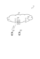
- FIG. 1 is a schematic diagram showing the overall configuration of a wireless communication system 10.
- FIG. 2 is a functional block diagram of gNB100.
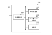
- FIG. 3 is a functional block diagram of UE 200.
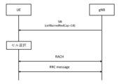
- FIG. 4 is a diagram showing an example of access restriction according to the second operation example.
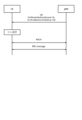
- FIG. 5 is a diagram showing an example of access restriction according to the fourth operation example.
- FIG. 6 is a diagram showing an example of access restriction according to the fifth operation example.
- FIG. 7 is a diagram showing a configuration example (part) of an SIB according to the second operation example.
- FIG. 8 is a diagram showing a configuration example (part) of an SIB related to the operation example 4.
- FIG. 9 is a diagram showing a configuration example (part) of the SIB according to the fifth example.
- FIG. 10 is a diagram showing an example of the hardware configuration of gNB100 and UE200.
- FIG. 11 is a diagram showing an example of the configuration of a vehicle 2001.
- FIG. 1 is an overall schematic configuration diagram of a wireless communication system 10 according to this embodiment.
- the wireless communication system 10 is a wireless communication system conforming to 5G New Radio (NR) and includes a Next Generation-Radio Access Network 20 (hereinafter, NG-RAN 20) and a terminal 200 (User Equipment 200, hereinafter, UE 200).
- NR 5G New Radio
- NG-RAN 20 Next Generation-Radio Access Network 20
- UE 200 User Equipment 200
- the wireless communication system 10 may be a wireless communication system conforming to a method called Beyond 5G, 5G Evolution, or 6G.
- NG-RAN 20 includes a radio base station 100 (hereinafter, gNB 100).
- gNB 100 radio base station 100
- the specific configuration of the radio communication system 10, including the number of gNBs and UEs, is not limited to the example shown in FIG. 1.
- NG-RAN20 actually includes multiple NG-RAN Nodes, specifically gNBs (or ng-eNBs), and is connected to a 5G-compliant core network (5GC, not shown).
- NG-RAN20 is connected to an Access and Mobility Management Function (AMF), which is included in the 5G system architecture and provides access and mobility management functions for UE200, and a Session Management Function (SMF), which provides session management functions.
- AMF Access and Mobility Management Function
- SMF Session Management Function
- UDM/UDR Unified Data Management/User Data Repository
- the gNB100 is a radio base station conforming to NR, and performs wireless communication conforming to NR with the UE200.
- the gNB100 may be composed of a CU (Central Unit) and a DU (Distributed Unit), and the DU may be separated from the CU and installed in a different geographical location.
- CU Central Unit
- DU Distributed Unit
- the gNB100 and UE200 are capable of supporting Massive MIMO, which generates more directional beams by controlling the radio signals transmitted from multiple antenna elements, Carrier Aggregation (CA), which bundles together multiple component carriers (CCs), and Dual Connectivity (DC), which enables simultaneous communication between the UE and multiple NG-RAN nodes.
- Massive MIMO which generates more directional beams by controlling the radio signals transmitted from multiple antenna elements
- CA Carrier Aggregation
- CCs component carriers
- DC Dual Connectivity
- the movement range of UE200 may be limited to within a specific area. Specifically, the movement range of UE200 may be limited to within one or more specific cells formed by gNB100. Alternatively, UE200 may hardly move and the movement range may be limited to within almost the same cell.
- a UE whose movement range is limited in this way may be determined to be in a low mobility state.
- a UE that hardly moves and whose movement range is limited to within the same cell may be determined to be in a stationary state.
- the stationary state may be included in the low mobility state as one aspect of the low mobility state.
- the low mobility state may be included in the stationary state as one aspect of the stationary state.
- Low mobility and stationary may also be expressed by other synonymous terms, such as motionless, parked, immobilized, stopped, halted, unmoving, and static (hereinafter, the term low mobility will be used for consistency).
- the capabilities of UE200 may be reduced.
- the capabilities to be reduced are not particularly limited, but may include reduced (or restricted, reduced, etc.) capabilities (operations) related to measurements for radio resource management (RRM).
- RRM radio resource management
- RedCap UE Reduced UE capability
- RedCap UE may be interpreted as a category of UE used for, for example, industrial wireless sensors, video surveillance, and wearable devices.
- a RedCap UE may not necessarily have reduced capabilities and may be interpreted as a UE for URLLC (Ultra-Reliable and Low Latency Communications) or for IoT (Internet of Things), etc.
- a RedCap UE may also be referred to as a specific type of UE.
- a non-RedCap UE may be interpreted as a UE with normal capabilities (normal UE) or a UE for enhanced Mobile Broadband (eMBB).
- normal UE normal capabilities
- eMBB enhanced Mobile Broadband
- RedCap UE is specified in 3GPP Release-17, and may have different numbers of implemented receiving antennas (which may also be called RX branches). Specifically, there may be RedCap UEs with one receiving antenna (1 RX branch) and RedCap UEs with two receiving antennas (2 RX branches). However, the number of receiving antennas does not necessarily have to be limited to 1 RX branch and 2 RX branches.
- the functionality (capabilities) of the RedCap UE may be further reduced. Specifically, compared to a RedCap UE, the bandwidth and peak data rate may be further restricted.
- a RedCap UE may be specified in 3GPP Release-18, and may be called an eRedCap UE (enhanced reduced UE capability) to distinguish it from a RedCap UE in Release-17.
- the baseband (BB) bandwidth used for transmitting and receiving a specific channel may be limited to 5 MHz (usually 20 MHz), and the peak data rate may be further reduced by changing certain parameters.
- the subcarrier spacing (SCS) may be 15 kHz or 30 kHz.
- a RedCap UE with reduced capabilities compared to a normal terminal may be called a first type terminal
- an eRedCap UE with even reduced capabilities compared to a RedCap UE may be called a second type terminal.
- the channels include a control channel and a data channel.
- the control channels include PDCCH (Physical Downlink Control Channel), PUCCH (Physical Uplink Control Channel), PRACH (Physical Random Access Channel), and PBCH (Physical Broadcast Channel), etc.
- Data channels also include PDSCH (Physical Downlink Shared Channel) and PUSCH (Physical Uplink Shared Channel).
- PDSCH Physical Downlink Shared Channel
- PUSCH Physical Uplink Shared Channel
- FIG. 2 is a functional block diagram of the gNB100.
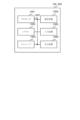
- FIG. 3 is a functional block diagram of the UE200. Note that in FIG. 2 and FIG. 3, only the main functional blocks relevant to the description of the embodiment are shown, and that the gNB100 and UE200 have other functional blocks (e.g., a power supply unit, etc.). Also, FIG. 2 and FIG. 3 show the functional block configuration of the gNB100 and UE200, and for the hardware configuration, please refer to FIG. 6.
- the gNB 100 includes a wireless communication unit 110, an Xn processing unit 120, an RRC processing unit 130, and a control unit 140.
- the wireless communication unit 110 transmits downlink signals (DL signals) that comply with NR.
- the wireless communication unit 110 also receives uplink signals (UL signals) that comply with NR.
- the Xn processing unit 120 processes messages via an Xn interface, which is a type of interface between RAN (Radio Access Network) nodes. Specifically, the Xn processing unit 120 can send and receive messages that comply with XnAP (Application Protocol). More specifically, the Xn processing unit 120 may send and receive various messages that comply with XnAP defined in 3GPP TS38.423.
- the Xn processing unit 120 may transmit and receive various messages between the CU and DU in accordance with the F1AP defined in 3GPP TS38.473.
- the RRC processing unit 130 executes various processes in the radio resource control layer (RRC). For example, the RRC processing unit 130 can transmit an RRC Reconfiguration to the UE 200. The RRC processing unit 130 can also receive an RRC Reconfiguration Complete from the UE 200, which is a response to the RRC Reconfiguration.
- RRC radio resource control layer
- the RRC processing unit 130 may transmit notification information regarding access restrictions for RedCap UE and eRedCap UE to the UE 200. Specifically, the RRC processing unit 130 may notify the target cell of system information (SIB: System Information Block) regarding the access restrictions.
- SIB System Information Block
- the SIB that can report the contents of the access restriction may be SIB1 or another SIB.
- the contents of the access restriction may be based on the number of receiving antennas (1 RX branch or 2 RX branches) of the RedCap UE and/or eRedCap UE, or may be restrictions targeting either or both of the RedCap UE and eRedCap UE.
- the access restrictions for RedCap UE in 3GPP Release-17 may be referred to as first access restrictions, and the access restrictions for eRedCap UE in 3GPP Release-18 may be referred to as second access restrictions.
- the control unit 140 controls each functional block that constitutes the gNB 100.
- the control unit 140 executes control related to access restrictions for RedCap UE and eRedCap UE.
- control unit 140 can apply access restrictions to a cell (gNB100) for a specific type of UE (or all types of UE) depending on the capabilities of the gNB100 or the accommodation status of Non-RedCap UE, RedCap UE, and eRedCap UE in the cell.
- the access restrictions may be applied assuming a scenario in which Non-RedCap UEs and eRedCap UEs are mixed in a cell (called Scenario A), or a scenario in which Non-RedCap UEs, RedCap UEs and eRedCap UEs are mixed in a cell (Scenario B).
- the wireless communication unit 210 transmits an uplink signal (UL signal) that complies with NR.
- the wireless communication unit 210 also receives an uplink signal (DL signal) that complies with NR.
- the RRC processing unit 220 executes various processes in the radio resource control layer (RRC). Specifically, the RRC processing unit 220 can send and receive messages in the radio resource control layer.
- RRC radio resource control layer
- the RRC processing unit 220 can receive an RRC Reconfiguration from the network, specifically, from the NG-RAN 20. In addition, the RRC processing unit 220 can transmit an RRC Reconfiguration Complete, which is a response to the RRC Reconfiguration, to the network.
- the RRC processing unit 220 may also receive notification information including access restrictions to a cell of a RedCap UE (first access restrictions) and access restrictions to a cell of an eRedCap UE (second access restrictions).
- the first access restriction may correspond to cellBarredRedCap1Rx-r17, cellBarredRedCap2Rx-r17, halfDuplexRedCapAllowed-r17, intraFreqReselectionRedCap-r17, etc. in the RRC layer information elements (IEs).
- halfDuplexRedCapAllowed-r17 may indicate whether or not a half-duplex RedCap UE is allowed.
- intraFreqReselectionRedCap-r17 may indicate restrictions on the selection and reselection of cells in other frequency bands after access restriction.
- the second access restriction may correspond to cellBarredRedCap1Rx-r18, cellBarredRedCap2Rx-r18 (tentative names may be used) in the information elements (IEs) of the RRC layer.
- the second access restriction may also correspond to cellBarredRedCap-r18, intraFreqReselectionRedCap-r18 (tentative names).
- cellBarredRedCap-r18 may be targeted at eRedCap UE in general, rather than being based on the number of receiving antennas as in cellBarredRedCap1Rx-r18 and cellBarredRedCap2Rx-r18.
- intraFreqReselectionRedCap-r18 corresponds to intraFreqReselectionRedCap-r17, and may indicate restrictions regarding reselection within a frequency band.
- the handover processing unit 230 executes processing related to handover of the UE 200. Specifically, the handover processing unit 230 can execute handover processing when the UE 200 is a RedCap UE or an eRedCap UE.
- the handover processing unit 230 may measure the reception quality (such as Reference Signal Received Power (RSRP)) of the serving cell and neighboring cells (which may also be called peripheral cells) and perform a handover to a cell that satisfies conditions such as reception quality.
- RSRP Reference Signal Received Power
- the serving cell may simply be interpreted as the cell to which UE 200 is connected, but more precisely, in the case of an RRC_CONNECTED UE in which carrier aggregation (CA) is not configured, there is only one serving cell that constitutes the primary cell.
- CA carrier aggregation
- the serving cell may be interpreted as indicating a set of one or more cells including the primary cell and all secondary cells.
- the control unit 240 controls each functional block that constitutes the UE 200.
- the control unit 240 may execute various controls when the UE 200 is a RedCap UE or an eRedCap UE.
- control unit 240 may execute control according to the number of receiving antennas (1 RX branch/2 RX branches) of the UE 200, the bandwidth, the peak data rate, etc.
- the control unit 240 may execute control according to the number of receiving antennas (1 RX branch/2 RX branches) of the UE 200, the bandwidth, the peak data rate, etc.
- at least one of the cells available for handover or the radio resource management such as the measurement of reception quality and the measurement report may differ depending on the capabilities of the UE 200, such as the number of receiving antennas.
- the control unit 240 may also perform cell selection based on the contents of access restrictions for RedCap UE or eRedCap UE. Specifically, when access restrictions are applied to RedCap UE or eRedCap UE, the control unit 240 may halt access to the cell, specifically, connection processing in the RRC layer, etc.
- the control unit 240 may ignore the access restriction for RedCap UE when the notification information (system information) indicates access restriction for eRedCap UE. Specifically, when the RRC processing unit 220 receives system information including the above-mentioned IE indicating restriction for eRedCap UE, it may restrict access to the cell for a specific period of time or until an instruction to lift the restriction is given, but may ignore the access restriction even if the system information includes the above-mentioned IE indicating access restriction for RedCap UE.
- control unit 240 may ignore the access restriction for the RedCap UE, regardless of whether or not the notification information indicates access restriction for the eRedCap UE. In other words, when the UE 200 is an eRedCap UE, the control unit 240 may completely ignore the access restriction for the RedCap UE.
- the control unit 240 may also perform cell selection based on the access restrictions for RedCap UE in Release-17 (first access restrictions) and the access restrictions for eRedCap UE in Release-18 (second access restrictions), but may assume that when access to eRedCap UE is restricted by the second access restrictions, access to RedCap UE is also restricted. In other words, the control unit 240 may assume that when access to eRedCap UE is restricted, similar access restrictions also apply to RedCap UE.
- IE intraFreqReselectionRedCap-r17
- SIB1 system information
- Non-RedCap UE and eRedCap UE are mixed in a cell (Scenario A), or in a scenario where Non-RedCap UE, RedCap UE and eRedCap UE are mixed in a cell (Scenario B), the problem arises of how to classify and restrict access to RedCap UE and/or eRedCap UE.
- the eRedCap UE may operate according to the presence or absence of cell access restriction by cellBarredRedCap1Rx-r17 and cellBarredRedCap2Rx-r17.
- the eRedCap UE may not select the cell during the period when the access restriction is set (barred), and may select the cell when the access restriction is not set (Not barred).
- Fig. 4 shows an example of access restriction according to operation example 2.
- the SIB (which may be SIB1 or another SIB, the same applies below) may include cellBarredRedCap1Rx-r18 and cellBarredRedCap2Rx-r18, and the eRedCap UE may operate according to the IE.
- Figure 7 shows an example (part) of the configuration of an SIB related to operation example 2.
- the eRedCap UE may operate according to whether or not access to the cell is restricted by cellBarredRedCap1Rx-r18 and cellBarredRedCap2Rx-r18.
- the eRedCap UE may not select the cell during the period when access is restricted (barred), and may select the cell when access is not restricted (Not barred).
- the eRedCap UE may ignore cellBarredRedCap1Rx-r17 and cellBarredRedCap2Rx-r17. If cellBarredRedCap1Rx-r18 or cellBarredRedCap2Rx-r18 is not set, the eRedCap UE may operate according to cellBarredRedCap1Rx-r17 and cellBarredRedCap2Rx-r17.
- An eRedCap UE may operate according to cellBarredRedCap1Rx-r18 or cellBarredRedCap2Rx-r18.
- An eRedCap UE may ignore cellBarredRedCap1Rx-r17 and cellBarredRedCap2Rx-r17 regardless of whether cellBarredRedCap1Rx-r18 or cellBarredRedCap2Rx-r18 is set or not.
- Fig. 5 shows an example of access restriction according to operation example 4.
- the SIB may include cellBarredRedCap-r18, and the eRedCap UE may operate according to the IE.
- FIG. 8 shows a configuration example (part) of an SIB related to operation example 4.
- the network may control access restrictions by using cellBarredRedCap-r18 together with cellBarredRedCap1Rx-r17 and cellBarredRedCap2Rx-r17.
- cellBarredRedCap-r18 may be set to barred
- cellBarredRedCap1Rx-r17 and cellBarredRedCap2Rx-r17 may be used to control the barring of RedCap UEs in 1 RX branch and/or 2 RX branch. If cellBarredRedCap-r18 is set to not barred, this may mean that the cell does not apply access barring to eRedCap UEs.
- the network may perform access restriction for eRedCap UEs using halfDuplexRedCapAllowed-r17.
- the network may also perform access restriction for eRedCap UEs using intraFreqReselectionRedCap-r17.
- Figure 6 shows an example of access restriction related to operation example 5.
- Figure 9 shows an example (part) of the SIB configuration related to operation example 5.
- the network may newly define halfDuplexRedCapAllowed-r18 and perform access restriction for half-duplex FDD eRedCap UEs. In this case, the eRedCap UE may ignore halfDuplexRedCapAllowed-r17.
- the network may also specify a new intraFreqReselectionRedCap-r18 to restrict selection/reselection to other intra-frequency cells after restricting access of an eRedCap UE to a cell.
- the eRedCap UE may ignore intraFreqReselectionRedCap-r17.
- gNB100 and UE200 can implement appropriate cell access restrictions even when RedCap UE and eRedCap UE are mixed.
- each functional block may be realized using one device that is physically or logically coupled, or may be realized using two or more devices that are physically or logically separated and connected directly or indirectly (e.g., using wires, wirelessly, etc.) and these multiple devices.
- the functional blocks may be realized by combining the one device or the multiple devices with software.
- FIG. 10 is a diagram showing an example of the hardware configuration of the device.
- the device may be configured as a computer device including a processor 1001, a memory 1002, a storage 1003, a communication device 1004, an input device 1005, an output device 1006, and a bus 1007.
- apparatus can be interpreted as a circuit, device, unit, etc.
- the hardware configuration of the apparatus may be configured to include one or more of the devices shown in the figure, or may be configured to exclude some of the devices.
- Each functional block of the device (see Figures 2 and 3) is realized by any hardware element of the computer device, or a combination of the hardware elements.
- the processor 1001 for example, runs an operating system to control the entire computer.
- the processor 1001 may be configured as a central processing unit (CPU) that includes an interface with peripheral devices, a control unit, an arithmetic unit, registers, etc.
- CPU central processing unit
- the processor 1001 also reads out programs (program codes), software modules, data, etc. from at least one of the storage 1003 and the communication device 1004 into the memory 1002, and executes various processes according to these.
- the programs used are those that cause a computer to execute at least some of the operations described in the above-mentioned embodiments.
- the various processes described above may be executed by one processor 1001, or may be executed simultaneously or sequentially by two or more processors 1001.
- the processor 1001 may be implemented by one or more chips.
- the programs may be transmitted from a network via a telecommunications line.
- Memory 1002 is a computer-readable recording medium and may be composed of, for example, at least one of Read Only Memory (ROM), Erasable Programmable ROM (EPROM), Electrically Erasable Programmable ROM (EEPROM), Random Access Memory (RAM), etc.
- Memory 1002 may also be called a register, cache, main memory, etc.
- Memory 1002 can store a program (program code), software module, etc. capable of executing a method according to one embodiment of the present disclosure.
- the communication device 1004 may be configured to include a high-frequency switch, a duplexer, a filter, a frequency synthesizer, etc., to realize, for example, at least one of Frequency Division Duplex (FDD) and Time Division Duplex (TDD).
- FDD Frequency Division Duplex
- TDD Time Division Duplex
- the input device 1005 is an input device (e.g., a keyboard, a mouse, a microphone, a switch, a button, a sensor, etc.) that accepts input from the outside.
- the output device 1006 is an output device (e.g., a display, a speaker, an LED lamp, etc.) that performs output to the outside. Note that the input device 1005 and the output device 1006 may be integrated into one structure (e.g., a touch panel).
- each device such as the processor 1001 and the memory 1002 is connected by a bus 1007 for communicating information.
- the bus 1007 may be configured using a single bus, or may be configured using different buses between each device.
- the device may be configured to include hardware such as a microprocessor, a digital signal processor (DSP), an application specific integrated circuit (ASIC), a programmable logic device (PLD), or a field programmable gate array (FPGA), and some or all of the functional blocks may be realized by the hardware.
- DSP digital signal processor
- ASIC application specific integrated circuit
- PLD programmable logic device
- FPGA field programmable gate array
- the processor 1001 may be implemented using at least one of these pieces of hardware.
- LTE Long Term Evolution
- LTE-A LTE-Advanced
- 5G 5th generation mobile communication system
- 6G 6th generation mobile communication system
- xth generation mobile communication system The present invention may be applied to at least one of systems using LTE, LTE-A, LTE-G (xG) (x is, for example, an integer or decimal point), Future Radio Access (FRA), New Radio (NR), W-CDMA (registered trademark), GSM (registered trademark), CDMA2000, Ultra Mobile Broadband (UMB), IEEE 802.11 (Wi-Fi (registered trademark)), IEEE 802.16 (WiMAX (registered trademark)), IEEE 802.20, Ultra-WideBand (UWB), Bluetooth (registered trademark), and other appropriate systems, and next-generation systems that are based on and extend these systems
- certain operations that are described as being performed by a base station may in some cases also be performed by its upper node.
- a network consisting of one or more network nodes having a base station
- various operations performed for communication with a terminal may be performed by at least one of the base station and other network nodes other than the base station (such as, but not limited to, an MME or S-GW).
- the above example shows a case where there is one other network node other than the base station, it may also be a combination of multiple other network nodes (such as an MME and an S-GW).
- the input and output information may be stored in a specific location (e.g., memory) or may be managed using a management table.
- the input and output information may be overwritten, updated, or appended.
- the output information may be deleted.
- the input information may be sent to another device.
- the determination may be based on a value represented by one bit (0 or 1), a Boolean value (true or false), or a numerical comparison (e.g., with a predetermined value).
- notification of specific information is not limited to being done explicitly, but may be done implicitly (e.g., not notifying the specific information).
- Software shall be construed broadly to mean instructions, instruction sets, code, code segments, program code, programs, subprograms, software modules, applications, software applications, software packages, routines, subroutines, objects, executable files, threads of execution, procedures, functions, etc., whether referred to as software, firmware, middleware, microcode, hardware description language, or otherwise.
- software, instructions, information, etc. may be transmitted and received over a transmission medium.
- a transmission medium For example, if software is transmitted from a website, server, or other remote source using at least one of wired technologies (such as coaxial cable, fiber optic cable, twisted pair, Digital Subscriber Line (DSL)), and/or wireless technologies (such as infrared, microwave, etc.), then at least one of these wired and/or wireless technologies is included within the definition of a transmission medium.
- wired technologies such as coaxial cable, fiber optic cable, twisted pair, Digital Subscriber Line (DSL)
- wireless technologies such as infrared, microwave, etc.
- the information, signals, etc. described in this disclosure may be represented using any of a variety of different technologies.
- the data, instructions, commands, information, signals, bits, symbols, chips, etc. that may be referred to throughout the above description may be represented by voltages, currents, electromagnetic waves, magnetic fields or magnetic particles, optical fields or photons, or any combination thereof.
- the channel and the symbol may be a signal (signaling).
- the signal may be a message.
- the component carrier (CC) may be called a carrier frequency, a cell, a frequency carrier, etc.
- system and “network” are used interchangeably.
- a radio resource may be indicated by an index.
- the names used for the above-mentioned parameters are not limiting in any respect. Furthermore, the formulas etc. using these parameters may differ from those explicitly disclosed in this disclosure.
- the various channels (e.g., PUCCH, PDCCH, etc.) and information elements may be identified by any suitable names, and therefore the various names assigned to these various channels and information elements are not limiting in any respect.
- Base station BS
- wireless base station fixed station
- NodeB NodeB
- eNodeB eNodeB
- gNodeB gNodeB
- a base station can accommodate one or more (e.g., three) cells (also called sectors). If a base station accommodates multiple cells, the overall coverage area of the base station can be divided into multiple smaller areas, and each smaller area can also provide communication services by a base station subsystem (e.g., a small indoor base station (Remote Radio Head: RRH)).
- a base station subsystem e.g., a small indoor base station (Remote Radio Head: RRH)
- cell refers to part or all of the coverage area of a base station and/or a base station subsystem that provides communication services within that coverage.
- a base station transmitting information to a terminal may be interpreted as the base station instructing the terminal to control or operate based on the information.
- MS Mobile Station
- UE User Equipment
- a mobile station may also be referred to by those skilled in the art as a subscriber station, mobile unit, subscriber unit, wireless unit, remote unit, mobile device, wireless device, wireless communication device, remote device, mobile subscriber station, access terminal, mobile terminal, wireless terminal, remote terminal, handset, user agent, mobile client, client, or some other suitable terminology.
- At least one of the base station and the mobile station may be called a transmitting device, a receiving device, a communication device, etc.
- At least one of the base station and the mobile station may be a device mounted on a moving object, or the moving object itself, etc.
- the moving object may be a vehicle (e.g., a car, an airplane, etc.), an unmanned moving object (e.g., a drone, an autonomous vehicle, etc.), or a robot (manned or unmanned).
- At least one of the base station and the mobile station may also include devices that do not necessarily move during communication operations.
- at least one of the base station and the mobile station may be an Internet of Things (IoT) device such as a sensor.
- IoT Internet of Things
- the base station in the present disclosure may be interpreted as a mobile station (user terminal, the same applies below).
- each aspect/embodiment of the present disclosure may be applied to a configuration in which communication between a base station and a mobile station is replaced with communication between multiple mobile stations (which may be called, for example, Device-to-Device (D2D), Vehicle-to-Everything (V2X), etc.).
- the mobile station may be configured to have the functions of a base station.
- terms such as "uplink” and "downlink” may be interpreted as terms corresponding to communication between terminals (for example, "side”).
- the uplink channel, downlink channel, etc. may be interpreted as a side channel (or side link).
- the mobile station in this disclosure may be interpreted as a base station.
- the base station may be configured to have the functions of the mobile station.
- a radio frame may be composed of one or more frames in the time domain. Each of the one or more frames in the time domain may be called a subframe. A subframe may further be composed of one or more slots in the time domain. A subframe may have a fixed time length (e.g., 1 ms) that is independent of numerology.
- Numerology may be a communication parameter that applies to at least one of the transmission and reception of a signal or channel. Numerology may indicate, for example, at least one of the following: Subcarrier Spacing (SCS), bandwidth, symbol length, cyclic prefix length, Transmission Time Interval (TTI), number of symbols per TTI, radio frame structure, a particular filtering operation performed by the transceiver in the frequency domain, a particular windowing operation performed by the transceiver in the time domain, etc.
- SCS Subcarrier Spacing
- TTI Transmission Time Interval
- radio frame structure a particular filtering operation performed by the transceiver in the frequency domain, a particular windowing operation performed by the transceiver in the time domain, etc.
- a slot may consist of one or more symbols in the time domain (e.g., Orthogonal Frequency Division Multiplexing (OFDM) symbols, Single Carrier Frequency Division Multiple Access (SC-FDMA) symbols, etc.).
- OFDM Orthogonal Frequency Division Multiplexing
- SC-FDMA Single Carrier Frequency Division Multiple Access
- a slot may be a numerology-based unit of time.
- a slot may include multiple minislots. Each minislot may consist of one or multiple symbols in the time domain. A minislot may also be called a subslot. A minislot may consist of fewer symbols than a slot.
- a PDSCH (or PUSCH) transmitted in a time unit larger than a minislot may be called PDSCH (or PUSCH) mapping type A.
- a PDSCH (or PUSCH) transmitted using a minislot may be called PDSCH (or PUSCH) mapping type B.
- Radio frame, subframe, slot, minislot, and symbol all represent time units for transmitting signals. Radio frame, subframe, slot, minislot, and symbol may each be referred to by a different name that corresponds to the radio frame, subframe, slot, minislot, and symbol.
- one subframe may be called a transmission time interval (TTI)
- TTI transmission time interval
- multiple consecutive subframes may be called a TTI
- one slot or one minislot may be called a TTI.
- at least one of the subframe and the TTI may be a subframe (1 ms) in existing LTE, a period shorter than 1 ms (e.g., 1-13 symbols), or a period longer than 1 ms.
- the unit expressing the TTI may be called a slot, minislot, etc., instead of a subframe.
- TTI refers to, for example, the smallest time unit for scheduling in wireless communication.
- a base station schedules each user terminal by allocating radio resources (such as frequency bandwidth and transmission power that can be used by each user terminal) in TTI units.
- radio resources such as frequency bandwidth and transmission power that can be used by each user terminal
- the TTI may be a transmission time unit for a channel-coded data packet (transport block), a code block, a code word, etc., or may be a processing unit for scheduling, link adaptation, etc.
- the time interval e.g., the number of symbols
- the time interval in which a transport block, a code block, a code word, etc. is actually mapped may be shorter than the TTI.
- one slot or one minislot when called a TTI, one or more TTIs (i.e., one or more slots or one or more minislots) may be the minimum time unit of scheduling.
- the number of slots (minislots) that constitute the minimum time unit of scheduling may be controlled.
- a TTI having a time length of 1 ms may be referred to as a normal TTI (TTI in LTE Rel. 8-12), normal TTI, long TTI, normal subframe, normal subframe, long subframe, slot, etc.
- TTI shorter than a normal TTI may be referred to as a shortened TTI, short TTI, partial or fractional TTI, shortened subframe, short subframe, minislot, subslot, slot, etc.
- a long TTI (e.g., a normal TTI, a subframe, etc.) may be interpreted as a TTI having a time length of more than 1 ms
- a short TTI e.g., a shortened TTI, etc.
- a resource block is a resource allocation unit in the time domain and frequency domain, and may include one or more consecutive subcarriers in the frequency domain.
- the number of subcarriers included in an RB may be the same regardless of the numerology, and may be, for example, 12.
- the number of subcarriers included in an RB may be determined based on the numerology.
- the time domain of an RB may include one or more symbols and may be one slot, one minislot, one subframe, or one TTI in length.
- One TTI, one subframe, etc. may each be composed of one or more resource blocks.
- one or more RBs may also be referred to as a physical resource block (PRB), a sub-carrier group (SCG), a resource element group (REG), a PRB pair, an RB pair, etc.
- PRB physical resource block
- SCG sub-carrier group
- REG resource element group
- PRB pair an RB pair, etc.
- a resource block may be composed of one or more resource elements (RE).
- RE resource elements
- one RE may be a radio resource area of one subcarrier and one symbol.
- a Bandwidth Part which may also be referred to as a partial bandwidth, may represent a subset of contiguous common resource blocks (RBs) for a given numerology on a given carrier, where the common RBs may be identified by an index of the RB relative to a common reference point of the carrier.
- PRBs may be defined in a BWP and numbered within that BWP.
- the BWP may include a BWP for UL (UL BWP) and a BWP for DL (DL BWP).
- UL BWP UL BWP
- DL BWP DL BWP
- One or more BWPs may be configured for a UE within one carrier.
- At least one of the configured BWPs may be active, and the UE may not expect to transmit or receive a given signal/channel outside the active BWP.
- BWP bitmap
- any reference to elements using designations such as “first,” “second,” etc., used in this disclosure does not generally limit the quantity or order of those elements. These designations may be used in this disclosure as a convenient way of distinguishing between two or more elements. Thus, a reference to a first and a second element does not imply that only two elements may be employed therein or that the first element must precede the second element in some way.
- determining may encompass a wide variety of actions. “Determining” and “determining” may include, for example, judging, calculating, computing, processing, deriving, investigating, looking up, search, inquiry (e.g., searching in a table, database, or other data structure), ascertaining something as being “determined” or “determined,” and the like.
- a and B are different may mean “A and B are different from each other.”
- the term may also mean “A and B are each different from C.”
- Terms such as “separate” and “combined” may also be interpreted in the same way as “different.”
- the information service unit 2012 is composed of various devices, such as a car navigation system, an audio system, speakers, a television, and a radio, for providing (outputting) various information such as driving information, traffic information, and entertainment information, and one or more ECUs for controlling these devices.
- the information service unit 2012 uses information acquired from external devices via the communication module 2013, etc., to provide various multimedia information and multimedia services to the occupants of the vehicle 1.
- the information service unit 2012 may include input devices (e.g., a keyboard, a mouse, a microphone, a switch, a button, a sensor, a touch panel, etc.) that accept input from the outside, and may also include output devices (e.g., a display, a speaker, an LED lamp, a touch panel, etc.) that perform output to the outside.
- input devices e.g., a keyboard, a mouse, a microphone, a switch, a button, a sensor, a touch panel, etc.
- output devices e.g., a display, a speaker, an LED lamp, a touch panel, etc.
- the driving assistance system unit 2030 is composed of various devices that provide functions for preventing accidents and reducing the driving burden on the driver, such as a millimeter wave radar, LiDAR (Light Detection and Ranging), a camera, a positioning locator (e.g., GNSS, etc.), map information (e.g., high definition (HD) map, autonomous vehicle (AV) map, etc.), a gyro system (e.g., IMU (Inertial Measurement Unit), INS (Inertial Navigation System), etc.), AI (Artificial Intelligence) chip, and an AI processor, as well as one or more ECUs that control these devices.
- the driving assistance system unit 2030 also transmits and receives various information via the communication module 2013 to realize driving assistance functions or autonomous driving functions.
- the communication module 2013 can communicate with the microprocessor 2031 and components of the vehicle 1 via the communication port.
- the communication module 2013 transmits and receives data via the communication port 2033 between the drive unit 2002, steering unit 2003, accelerator pedal 2004, brake pedal 2005, shift lever 2006, left and right front wheels 2007, left and right rear wheels 2008, axle 2009, microprocessor 2031 and memory (ROM, RAM) 2032 in electronic control unit 2010, and sensors 2021 to 2028, which are provided on the vehicle 2001.
- the communication module 2013 is a communication device that can be controlled by the microprocessor 2031 of the electronic control unit 2010 and can communicate with an external device. For example, it transmits and receives various information to and from the external device via wireless communication.
- the communication module 2013 may be located either inside or outside the electronic control unit 2010.
- the external device may be, for example, a base station, a mobile station, etc.
- the communication module 2013 receives various information (traffic information, signal information, vehicle distance information, etc.) transmitted from an external device, and displays it on the information service unit 2012 provided in the vehicle.
- the information service unit 2012 may be called an output unit that outputs information (for example, outputs information to a device such as a display or speaker based on the PDSCH (or data/information decoded from the PDSCH) received by the communication module 2013).
- the communication module 2013 also stores various information received from an external device in a memory 2032 that can be used by the microprocessor 2031.
- a first feature is a terminal including a receiver that receives broadcast information including access restrictions to a cell for a first type terminal having reduced capabilities compared to a normal terminal and a second type terminal having capabilities further reduced than the first type terminal, and a controller that executes cell selection based on the contents of the access restrictions, and the controller is a terminal that ignores the access restrictions for the first type terminal when the access restrictions for the second type terminal are indicated by the broadcast information.
- the second feature is the first feature, in which the control unit ignores the access restriction for the first type of terminal, regardless of whether the notification information indicates the access restriction for the second type of terminal.
- the third feature is a terminal that includes a receiver that receives notification information including a first access restriction to a cell for a first type of terminal with reduced capabilities compared to a normal terminal, and a second access restriction to the cell for a second type of terminal with even reduced capabilities compared to the first type of terminal, and a controller that executes cell selection based on the first access restriction and the second access restriction, and assumes that when access to the second type of terminal is restricted by the second access restriction, access to the first type of terminal is also restricted.
- Wireless Communication Systems 20 NG-RAN 100 gNB 110 wireless communication unit 120 Xn processing unit 130 RRC processing unit 140 control unit 200 UE 210 wireless communication unit 220 RRC processing unit 230 handover processing unit 240 control unit 1001 processor 1002 memory 1003 storage 1004 communication device 1005 input device 1006 output device 1007 bus 2001 vehicle 2002 drive unit 2003 steering unit 2004 accelerator pedal 2005 brake pedal 2006 shift lever 2007 left and right front wheels 2008 left and right rear wheels 2009 axle 2010 electronic control unit 2012 information service unit 2013 communication module 2021 current sensor 2022 rotation speed sensor 2023 air pressure sensor 2024 vehicle speed sensor 2025 acceleration sensor 2026 brake pedal sensor 2027 shift lever sensor 2028 Object detection sensor 2029 Accelerator pedal sensor 2030 Driving assistance system section 2031 Microprocessor 2032 Memory (ROM, RAM) 2033 communication port
Landscapes
- Engineering & Computer Science (AREA)
- Computer Security & Cryptography (AREA)
- Computer Networks & Wireless Communication (AREA)
- Signal Processing (AREA)
- Mobile Radio Communication Systems (AREA)
Abstract
Description
図1は、本実施形態に係る無線通信システム10の全体概略構成図である。無線通信システム10は、5G New Radio(NR)に従った無線通信システムであり、Next Generation-Radio Access Network 20(以下、NG-RAN20、及び端末200(User Equipment 200、以下、UE200)を含む。
次に、無線通信システム10の機能ブロック構成について説明する。具体的には、gNB100及びUE200の機能ブロック構成について説明する。
図2に示すように、gNB100は、無線通信部110、Xn処理部120、RRC処理部130及び制御部140を備える。
図3に示すように、UE200は、無線通信部210、RRC処理部220、ハンドオーバー処理部230及び制御部240を備える。なお、ここでは、UE200は、eRedCap UEであることを想定する。但し、UE200は、eRedCap UEに該当すると同時にRedCap UEにも該当してもよい。
次に、無線通信システム10の動作について説明する。具体的には、UE200がRedCap UE及びeRedCap UEに対するアクセス規制に関する動作例について説明する。
Release-17のRedCap UEのセルへのアクセス規制のため、システム情報(SIB1)には、新たな情報要素(IE)であるintraFreqReselectionRedCap-r17が規定されている。
(3.2.1)動作例1
eRedCap UEは、cellBarredRedCap1Rx-r17及びcellBarredRedCap2Rx-r17によるセルへのアクセス規制有無に従って動作してよい。eRedCap UEは、アクセス規制が設定(barred)されている期間、当該セルを選択せず、アクセス規制が設定されていない(Not barred)の場合、当該セルを選択してもよい。
図4は、動作例2に係るアクセス規制の例を示す。図4に示すように、SIB(SIB1でもよいし、他のSIBでもよい、以下同)には、cellBarredRedCap1Rx-r18及びcellBarredRedCap2Rx-r18を含めることができ、eRedCap UEは、当該IEに従って動作してよい。
eRedCap UEは、cellBarredRedCap1Rx-r18またはcellBarredRedCap2Rx-r18に従って動作してよい。 eRedCap UEは、cellBarredRedCap1Rx-r18またはcellBarredRedCap2Rx-r18が設定されているかいないかに関わらず、cellBarredRedCap1Rx-r17及びcellBarredRedCap2Rx-r17を無視してもよい。
図5は、動作例4に係るアクセス規制の例を示す。図5に示すように、SIBには、cellBarredRedCap-r18を含めることができ、eRedCap UEは、当該IEに従って動作してよい。
ネットワーク(gNB)は、halfDuplexRedCapAllowed-r17を用いてeRedCap UEに対するアクセス規制を実行してもよい。また、ネットワークは、intraFreqReselectionRedCap-r17を用いてeRedCap UEに対するアクセス規制を実行してもよい。
上述した実施形態によれば、RedCap UEに対するアクセス規制用の既存IE、及びeRedCap UEに対するアクセス規制用の新規IEを用いることによって、eRedCap UEと他の種類のUEとの混在シナリオ(シナリオA, B)においても、ネットワーク側の意図に応じた適切なアクセス規制を実現し得る。
以上、実施形態について説明したが、当該実施形態の記載に限定されるものではなく、種々の変形及び改良が可能であることは、当業者には自明である。
上述した開示は、以下のように表現されてもよい。第1の特徴は、通常端末よりも能力が低減された第1種端末、及び前記第1種端末よりもさらに能力が低減された第2種端末のセルへのアクセス規制を含む報知情報を受信する受信部と、前記アクセス規制の内容に基づいてセル選択を実行する制御部とを備え、前記制御部は、前記報知情報によって前記第2種端末に対する前記アクセス規制が示されている場合、前記第1種端末に対する前記アクセス規制を無視する端末である。
20 NG-RAN
100 gNB
110 無線通信部
120 Xn処理部
130 RRC処理部
140 制御部
200 UE
210 無線通信部
220 RRC処理部
230 ハンドオーバー処理部
240 制御部
1001 プロセッサ
1002 メモリ
1003 ストレージ
1004 通信装置
1005 入力装置
1006 出力装置
1007 バス
2001 車両
2002 駆動部
2003 操舵部
2004 アクセルペダル
2005 ブレーキペダル
2006 シフトレバー
2007 左右の前輪
2008 左右の後輪
2009 車軸
2010 電子制御部
2012 情報サービス部
2013 通信モジュール
2021 電流センサ
2022 回転数センサ
2023 空気圧センサ
2024 車速センサ
2025 加速度センサ
2026 ブレーキペダルセンサ
2027 シフトレバーセンサ
2028 物体検出センサ
2029 アクセルペダルセンサ
2030 運転支援システム部
2031 マイクロプロセッサ
2032 メモリ(ROM, RAM)
2033 通信ポート
Claims (5)
- 通常端末よりも能力が低減された第1種端末、及び前記第1種端末よりもさらに能力が低減された第2種端末のセルへのアクセス規制を含む報知情報を受信する受信部と、
前記アクセス規制の内容に基づいてセル選択を実行する制御部と
を備え、
前記制御部は、前記報知情報によって前記第2種端末に対する前記アクセス規制が示されている場合、前記第1種端末に対する前記アクセス規制を無視する端末。 - 前記制御部は、前記報知情報によって前記第2種端末に対する前記アクセス規制が示されているか否かに関わらず、前記第1種端末に対する前記アクセス規制を無視する請求項1に記載の端末。
- 通常端末よりも能力が低減された第1種端末のセルへの第1アクセス規制と、前記第1種端末よりもさらに能力が低減された第2種端末の前記セルへの第2アクセス規制とを含む報知情報を受信する受信部と、
前記第1アクセス規制と前記第2アクセス規制とに基づいてセル選択を実行する制御部と
を備え、
前記第2アクセス規制によって前記第2種端末に対するアクセスが規制されている場合、前記第1種端末に対するアクセスも規制されていると想定する端末。 - 通常端末よりも能力が低減された第1種端末、及び前記第1種端末よりもさらに能力が低減された第2種端末のセルへのアクセス規制を含む報知情報を受信するステップと、
前記アクセス規制の内容に基づいてセル選択を実行するステップと、
前記報知情報によって前記第2種端末に対する前記アクセス規制が示されている場合、前記第1種端末に対する前記アクセス規制を無視するステップと
を含む端末による無線通信方法。 - 通常端末よりも能力が低減された第1種端末のセルへの第1アクセス規制と、前記第1種端末よりもさらに能力が低減された第2種端末の前記セルへの第2アクセス規制とを含む報知情報を受信するステップと、
前記第1アクセス規制と前記第2アクセス規制とに基づいてセル選択を実行するステップと、
前記第2アクセス規制によって前記第2種端末に対するアクセスが規制されている場合、前記第1種端末に対するアクセスも規制されていると想定するステップと
を含む端末による無線通信方法。
Priority Applications (3)
| Application Number | Priority Date | Filing Date | Title |
|---|---|---|---|
| PCT/JP2023/005833 WO2024171461A1 (ja) | 2023-02-17 | 2023-02-17 | 端末及び無線通信方法 |
| JP2025500609A JPWO2024171461A1 (ja) | 2023-02-17 | 2023-02-17 | |
| EP23922795.2A EP4668871A1 (en) | 2023-02-17 | 2023-02-17 | Terminal and wireless communication method |
Applications Claiming Priority (1)
| Application Number | Priority Date | Filing Date | Title |
|---|---|---|---|
| PCT/JP2023/005833 WO2024171461A1 (ja) | 2023-02-17 | 2023-02-17 | 端末及び無線通信方法 |
Publications (1)
| Publication Number | Publication Date |
|---|---|
| WO2024171461A1 true WO2024171461A1 (ja) | 2024-08-22 |
Family
ID=92421021
Family Applications (1)
| Application Number | Title | Priority Date | Filing Date |
|---|---|---|---|
| PCT/JP2023/005833 Ceased WO2024171461A1 (ja) | 2023-02-17 | 2023-02-17 | 端末及び無線通信方法 |
Country Status (3)
| Country | Link |
|---|---|
| EP (1) | EP4668871A1 (ja) |
| JP (1) | JPWO2024171461A1 (ja) |
| WO (1) | WO2024171461A1 (ja) |
-
2023
- 2023-02-17 WO PCT/JP2023/005833 patent/WO2024171461A1/ja not_active Ceased
- 2023-02-17 EP EP23922795.2A patent/EP4668871A1/en active Pending
- 2023-02-17 JP JP2025500609A patent/JPWO2024171461A1/ja active Pending
Non-Patent Citations (7)
| Title |
|---|
| 3GPP: "3rd Generation Partnership Project; Technical Specification Group Radio Access Network; NR; Radio Resource Control (RRC) protocol specification (Release 17", 3GPP TS 38.331 V17.2.0, September 2022 (2022-09-01) |
| 3GPP: "Revised WID on Enhanced support of reduced capability NR devices", RP-223544, 3GPP TSG RAN MEETING #98-E, December 2022 (2022-12-01) |
| JUSSI-PEKKA KOSKINEN, NOKIA, NOKIA SHANGHAI BELL: "On access restrictions for enhanced RedCap", 3GPP DRAFT; R2-2301332; TYPE DISCUSSION; NR_REDCAP_ENH-CORE, 3RD GENERATION PARTNERSHIP PROJECT (3GPP), MOBILE COMPETENCE CENTRE ; 650, ROUTE DES LUCIOLES ; F-06921 SOPHIA-ANTIPOLIS CEDEX ; FRANCE, vol. 3GPP RAN 2, no. Athens, GR; 20230227 - 20230303, 16 February 2023 (2023-02-16), Mobile Competence Centre ; 650, route des Lucioles ; F-06921 Sophia-Antipolis Cedex ; France, XP052245969 * |
| MIN ZHU, CATT: "Discussion on further complexity reduction for eRedCap UE", 3GPP DRAFT; R1-2211208; TYPE DISCUSSION; NR_REDCAP_ENH-CORE, 3RD GENERATION PARTNERSHIP PROJECT (3GPP), MOBILE COMPETENCE CENTRE ; 650, ROUTE DES LUCIOLES ; F-06921 SOPHIA-ANTIPOLIS CEDEX ; FRANCE, vol. 3GPP RAN 1, no. Toulouse, FR; 20221114 - 20221118, 7 November 2022 (2022-11-07), Mobile Competence Centre ; 650, route des Lucioles ; F-06921 Sophia-Antipolis Cedex ; France, XP052221773 * |
| See also references of EP4668871A1 |
| SERKAN DOST, SIERRA WIRELESS. S.A.: "Early indication and access restrictions for eRedCap UE", 3GPP DRAFT; R2-2301430; TYPE DISCUSSION, 3RD GENERATION PARTNERSHIP PROJECT (3GPP), MOBILE COMPETENCE CENTRE ; 650, ROUTE DES LUCIOLES ; F-06921 SOPHIA-ANTIPOLIS CEDEX ; FRANCE, vol. 3GPP RAN 2, no. Athens, GR; 20230227 - 20230303, 16 February 2023 (2023-02-16), Mobile Competence Centre ; 650, route des Lucioles ; F-06921 Sophia-Antipolis Cedex ; France, XP052246067 * |
| XUEMEI QIAO, XIAOMI: "Discussion on further complexity reduction for eRedCap UEs", 3GPP DRAFT; R1-2211372; TYPE DISCUSSION; NR_REDCAP_ENH-CORE, 3RD GENERATION PARTNERSHIP PROJECT (3GPP), MOBILE COMPETENCE CENTRE ; 650, ROUTE DES LUCIOLES ; F-06921 SOPHIA-ANTIPOLIS CEDEX ; FRANCE, vol. 3GPP RAN 1, no. Toulouse, FR; 20221114 - 20221118, 7 November 2022 (2022-11-07), Mobile Competence Centre ; 650, route des Lucioles ; F-06921 Sophia-Antipolis Cedex ; France, XP052221936 * |
Also Published As
| Publication number | Publication date |
|---|---|
| JPWO2024171461A1 (ja) | 2024-08-22 |
| EP4668871A1 (en) | 2025-12-24 |
Similar Documents
| Publication | Publication Date | Title |
|---|---|---|
| EP4429318A1 (en) | Wireless base station, wireless communication system, and wireless communication method | |
| JP7726447B2 (ja) | 端末、基地局、通信システム及び通信方法 | |
| WO2024171315A1 (ja) | 無線基地局及び無線通信方法 | |
| WO2023090401A1 (ja) | 無線通信ノード及び無線通信方法 | |
| WO2024069904A1 (ja) | 端末及び通信方法 | |
| WO2024171461A1 (ja) | 端末及び無線通信方法 | |
| EP4668866A1 (en) | Wireless base station and wireless communication method | |
| JP7768590B2 (ja) | 端末、及びモニタ方法 | |
| JP7839812B2 (ja) | 端末、基地局及び通信方法 | |
| EP4422247A1 (en) | Terminal, base station, wireless communication system, and wireless communication method | |
| JP2025155726A (ja) | 端末、無線基地局及び無線通信方法 | |
| WO2024171432A1 (ja) | 無線基地局及び無線通信方法 | |
| WO2024171311A1 (ja) | 無線基地局及び無線通信方法 | |
| JP2026041938A (ja) | 端末、及び基地局 | |
| WO2024219119A1 (ja) | 端末及び通信方法 | |
| WO2024069903A1 (ja) | 端末及び通信方法 | |
| WO2024201816A1 (ja) | 端末、基地局及び通信方法 | |
| WO2025022584A1 (ja) | 端末、基地局、及び通信方法 | |
| WO2025074554A1 (ja) | 端末 | |
| WO2025032662A1 (ja) | 端末、基地局、及び通信方法 | |
| WO2024069902A1 (ja) | 端末、基地局及び通信方法 | |
| WO2024100736A1 (ja) | 端末、基地局及び通信方法 | |
| WO2024100901A1 (ja) | 基地局 | |
| WO2025057340A1 (ja) | 端末及び通信方法 | |
| WO2024100892A1 (ja) | 端末、基地局及び通信方法 |
Legal Events
| Date | Code | Title | Description |
|---|---|---|---|
| 121 | Ep: the epo has been informed by wipo that ep was designated in this application |
Ref document number: 23922795 Country of ref document: EP Kind code of ref document: A1 |
|
| ENP | Entry into the national phase |
Ref document number: 2025500609 Country of ref document: JP Kind code of ref document: A |
|
| WWE | Wipo information: entry into national phase |
Ref document number: 2025500609 Country of ref document: JP |
|
| WWE | Wipo information: entry into national phase |
Ref document number: 2023922795 Country of ref document: EP |
|
| NENP | Non-entry into the national phase |
Ref country code: DE |
|
| ENP | Entry into the national phase |
Ref document number: 2023922795 Country of ref document: EP Effective date: 20250917 |
|
| WWP | Wipo information: published in national office |
Ref document number: 2023922795 Country of ref document: EP |