WO2024171885A1 - ねじ継手 - Google Patents
ねじ継手 Download PDFInfo
- Publication number
- WO2024171885A1 WO2024171885A1 PCT/JP2024/003871 JP2024003871W WO2024171885A1 WO 2024171885 A1 WO2024171885 A1 WO 2024171885A1 JP 2024003871 W JP2024003871 W JP 2024003871W WO 2024171885 A1 WO2024171885 A1 WO 2024171885A1
- Authority
- WO
- WIPO (PCT)
- Prior art keywords
- box
- pin
- seal surface
- thread
- threaded joint
- Prior art date
- Legal status (The legal status is an assumption and is not a legal conclusion. Google has not performed a legal analysis and makes no representation as to the accuracy of the status listed.)
- Ceased
Links
Images



Classifications
-
- F—MECHANICAL ENGINEERING; LIGHTING; HEATING; WEAPONS; BLASTING
- F16—ENGINEERING ELEMENTS AND UNITS; GENERAL MEASURES FOR PRODUCING AND MAINTAINING EFFECTIVE FUNCTIONING OF MACHINES OR INSTALLATIONS; THERMAL INSULATION IN GENERAL
- F16L—PIPES; JOINTS OR FITTINGS FOR PIPES; SUPPORTS FOR PIPES, CABLES OR PROTECTIVE TUBING; MEANS FOR THERMAL INSULATION IN GENERAL
- F16L15/00—Screw-threaded joints; Forms of screw-threads for such joints
- F16L15/04—Screw-threaded joints; Forms of screw-threads for such joints with additional sealings
-
- E—FIXED CONSTRUCTIONS
- E21—EARTH OR ROCK DRILLING; MINING
- E21B—EARTH OR ROCK DRILLING; OBTAINING OIL, GAS, WATER, SOLUBLE OR MELTABLE MATERIALS OR A SLURRY OF MINERALS FROM WELLS
- E21B17/00—Drilling rods or pipes; Flexible drill strings; Kellies; Drill collars; Sucker rods; Cables; Casings; Tubings
- E21B17/02—Couplings; joints
- E21B17/04—Couplings; joints between rod or the like and bit or between rod and rod or the like
- E21B17/042—Threaded
-
- F—MECHANICAL ENGINEERING; LIGHTING; HEATING; WEAPONS; BLASTING
- F16—ENGINEERING ELEMENTS AND UNITS; GENERAL MEASURES FOR PRODUCING AND MAINTAINING EFFECTIVE FUNCTIONING OF MACHINES OR INSTALLATIONS; THERMAL INSULATION IN GENERAL
- F16L—PIPES; JOINTS OR FITTINGS FOR PIPES; SUPPORTS FOR PIPES, CABLES OR PROTECTIVE TUBING; MEANS FOR THERMAL INSULATION IN GENERAL
- F16L15/00—Screw-threaded joints; Forms of screw-threads for such joints
- F16L15/001—Screw-threaded joints; Forms of screw-threads for such joints with conical threads
- F16L15/004—Screw-threaded joints; Forms of screw-threads for such joints with conical threads with axial sealings having at least one plastically deformable sealing surface
-
- F—MECHANICAL ENGINEERING; LIGHTING; HEATING; WEAPONS; BLASTING
- F16—ENGINEERING ELEMENTS AND UNITS; GENERAL MEASURES FOR PRODUCING AND MAINTAINING EFFECTIVE FUNCTIONING OF MACHINES OR INSTALLATIONS; THERMAL INSULATION IN GENERAL
- F16L—PIPES; JOINTS OR FITTINGS FOR PIPES; SUPPORTS FOR PIPES, CABLES OR PROTECTIVE TUBING; MEANS FOR THERMAL INSULATION IN GENERAL
- F16L15/00—Screw-threaded joints; Forms of screw-threads for such joints
- F16L15/06—Screw-threaded joints; Forms of screw-threads for such joints characterised by the shape of the screw-thread
Definitions
- This disclosure relates to threaded joints used to connect long pipes such as oil well pipes.
- oil wells In oil wells, natural gas wells, etc. (hereinafter collectively referred to as "oil wells"), casings that construct multiple stages of well walls and tubing that is placed inside the casing to produce oil and gas are used to extract underground resources.
- These casings and tubing are made up of many steel pipes connected in sequence, and threaded joints such as those shown in Patent Documents 1 to 4 below are used for these connections.
- Steel pipes used in oil wells are also called oil well tubular goods.
- Threaded joints are broadly divided into integral and coupling types.
- oil well pipes are directly connected to each other.
- one end of the oil well pipe has a female thread and the other end has a male thread
- the oil well pipes are connected to each other by screwing the male thread of one oil well pipe into the female thread of the other oil well pipe.
- oil well pipes are connected to each other via a tubular coupling.
- female threads are provided on both ends of the coupling
- male threads are provided on both ends of the oil well pipes. Then, one male thread of one oil well pipe is screwed into one female thread of the coupling, and one male thread of the other oil well pipe is screwed into the other female thread of the coupling, thereby connecting the oil well pipes to each other. That is, in the coupling type, of the pair of pipe materials to be connected, one pipe material is the oil well pipe, and the other pipe material is the coupling.
- the end of an OCTG on which a male thread is formed is called a pin because it includes an element that is inserted into a female thread formed on the OCTG or coupling.
- the end of an OCTG or coupling on which a female thread is formed is called a box because it includes an element that receives the male thread formed on the OCTG.
- slim type threaded joints are sometimes used, in which the maximum outer diameter of the joint, i.e. the outer diameter of the box, is approximately the same as the outer diameter of the OCTG body.
- Slim type threaded joints in which the outer diameter of the box is approximately the same as the outer diameter of the OCTG body are also called flush type threaded joints.
- Slim type threaded joints in which the outer diameter of the box is slightly larger than the outer diameter of the OCTG body are also called semi-flush type threaded joints.
- Patent Document 1 discloses a coupling-type screw joint that is not a slim type.
- the pin wall thickness and the box wall thickness near the inner seal provided on the outer periphery of the pin tip can both be sufficiently large, and sufficient sealing performance against internal and external pressure can be obtained with the inner seal alone, so the screw joint disclosed in Patent Document 1 does not have an outer seal.
- the pin wall thickness near the inner seal provided on the outer circumference of the pin near the tip of the pin becomes thin, making it difficult to ensure sealing performance against external pressure with the inner seal, so outer seal surfaces are often provided on the outer circumference of the base end of the pin and the inner circumference of the tip of the box, as disclosed in Patent Documents 2 and 3.
- the box wall thickness near the outer seal becomes relatively thin, but when external pressure acts on the outer circumference of the box, the contact pressure between the outer seal surfaces increases, so external pressure sealing can be ensured.
- the pin wall thickness near the inner seal becomes relatively thin, but when internal pressure acts on the inner circumference of the pin, the contact pressure between the inner seal surfaces increases, so internal pressure sealing can be ensured.
- Patent Document 2 discloses an integral slim-type threaded joint.
- an external shoulder surface is provided at the base end of the pin and the tip end of the box.
- Patent Document 3 discloses an integral type slim type threaded joint.
- This threaded joint has a two-stage thread structure with threaded portions located in front of and behind an intermediate shoulder.
- the pin is subjected to a diameter reduction process in the area including the internal male threaded portion. Therefore, the inner diameter of the tip of the pin is smaller than the inner diameter of the steel pipe with the box, and a step is formed between the inner surface of the steel pipe with the box and the inner surface of the steel pipe with the pin. Such a step is undesirable because it causes turbulence in the fluid flow inside the pipe.
- Patent Document 4 discloses an integral type slim threaded joint having an inner shoulder surface (8, 9), an inner seal surface (10, 12), a threaded portion (3, 4), an outer seal surface (34, 35), and an outer shoulder surface (32, 33).
- the inner shoulder and the outer shoulder are both provided within the wall thickness of the steel pipe, and the axial length of the threaded portion consisting of tapered threads is ensured according to the required strength, the taper angle of the tapered threads becomes small, the amount of tightening rotation work required to complete tightening increases, and the efficiency of the fastening work deteriorates.
- Patent Document 4 page 13, lines 7-9, mentions that the inner shoulder surfaces (8, 9), the inner seal surfaces (10, 12), and the housing (7) can be omitted. In this case, the structure will be similar to the threaded joint disclosed in Patent Document 2, and similar problems will be inherent.
- the objective of this disclosure is to provide a slim-type threaded joint that has excellent sealing performance against internal pressure and external pressure, excellent strength against compressive loads, and can maintain sealing performance against external pressure even when repeatedly loaded.
- the inventors of the present application considered placing a torque shoulder at the tip of the pin and placing an inner seal and an outer seal in front of and behind the threaded portion in order to ensure the contact area between the shoulder surfaces and the radial width required to form the threaded portion even in slim-type threaded joints.
- the inventors therefore considered deforming the pin and box in their elastic range when a compressive load is applied, bringing the stabbing flanks of the male and female threads into contact with each other and sharing part of the compressive load between the stabbing flanks.
- the tip opening of the box attempts to shrink and deform, while when the pin is pushed into the box, the pin outer seal surface forcibly expands the box outer seal surface radially outward, making it easier for damage to accumulate near the box outer seal surface.
- the threaded joint according to the present disclosure may be a threaded joint consisting of a tubular pin and a tubular box, in which the pin is screwed into the box to fasten the pin and the box together.
- the pin can have a male thread formed of a tapered thread on the outer periphery of the pin and gradually decreasing in diameter toward the tip, an internal pin seal surface on the outer periphery of the pin on the tip side of the male thread, a nose portion on the tip side of the internal pin seal surface and having an outer periphery surface that smoothly continues to the internal pin seal surface, a torque shoulder surface formed by the tip surface of the nose portion, and an external pin seal surface on the outer periphery of the pin on the base end side of the male thread.
- the box can have a female thread provided on the inner circumference of the box and engaging with the male thread in the fastened state, a box inner seal surface provided on the inner circumference of the box and contacting the pin inner seal surface in the fastened state, an unthreaded portion having an inner peripheral surface that faces radially with a gap from the outer peripheral surface of the nose portion in the fastened state, a torque shoulder surface that faces axially with the torque shoulder surface of the pin and contacts the torque shoulder surface of the pin in the fastened state, and a box outer seal surface provided on the outer circumference of the box and contacting the pin outer seal surface in the fastened state.
- the male and female threads may be configured such that, in a fastened state, when no axial compressive load is applied, a gap is formed between the stab flank of the male thread and the stab flank of the female thread, and when a predetermined axial compressive load is applied to the threaded joint, the pin and the box are elastically deformed, causing the stab flank of the male thread and the stab flank of the female thread to come into contact with each other, thereby transmitting a portion of the axial compressive load between these stab flanks.
- the pin outer seal surface and the box outer seal surface may have a shape that expands the diameter of the box seal surface when the pin fastened to the box is pushed toward the tip side of the box by an axial compression load.
- the taper angle of the pin outer seal surface and/or the box outer seal surface may be larger than the thread taper angle of the male thread and the female thread.
- the inclination degree of the thread taper is 1/6
- the inclination degree of the taper of the outer seal surface may be 1/4.
- the inclination degree of the taper is the diameter displacement amount relative to the axial length (diameter displacement amount/axial length).
- the taper angle is expressed as arctan (taper inclination degree/2).
- the shoulder angle defined as the angle between a straight line passing through the radial outer end and the radial inner end in the longitudinal section of the torque shoulder surface of the box and a plane perpendicular to the tube axis, is 0° or more and less than 10° (however, a positive angle is defined as when the radial outer end is located closer to the tip side than the radial inner end).
- This disclosure makes it possible to provide a slim-type threaded joint that has excellent sealing performance against internal pressure and external pressure, excellent strength against compressive loads, and can maintain sealing performance against external pressure even when repeatedly loaded.
- FIG. 1 is an overall vertical sectional view showing a fastened state of a threaded joint for oil well pipes according to an embodiment.
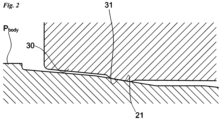
- FIG. 2 is an enlarged vertical sectional view of the vicinity of an outer seal of the threaded joint.
- FIG. 3 is an enlarged vertical sectional view showing the threaded joint in a threaded engaged state.
- FIG. 4 is an enlarged vertical sectional view showing the vicinity of the tip portion of the pin of the threaded joint.
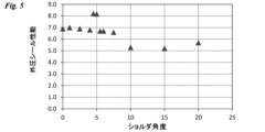
- FIG. 5 is a graph showing the results of a numerical analysis simulation using an elastic-plastic finite element method, illustrating the relationship between the shoulder angle and the minimum value of the evaluated contact pressure between the outer seal surfaces when repeatedly subjected to a combined load.
- the threaded joint is composed of a tubular pin and a tubular box having an opening for receiving the pin, and is a threaded joint in which the pin is screwed into the box to fasten the pin and the box.
- the pin may be provided at the end of a long pipe such as an oil well tubular pipe.
- the box may be provided at the end of a coupling or at the end of another long pipe.
- the pin is formed at the end of the long pipe, and the box is formed at the end of the coupling.
- the long pipe and the coupling may be made of metal such as steel, such as stainless steel, or a nickel-based alloy.
- the threaded joint comprises a pipe including a pipe body and the pin provided at the end of the pipe body, and a tubular coupling for connecting the pipe to another pipe, and the coupling may include the pipe body and the box provided at the end of the pipe body.
- the outer diameter of the pipe body and the box of the coupling may be 100% to 105% of the outer diameter of the pipe body, and the inner diameter of the pipe body of the coupling may be 90% to less than 100% of the inner diameter of the pipe body of the pipe.
- the inner diameter of the pipe body of the coupling is smaller than the inner diameter of the pipe body of the pipe, it is preferable that the vicinity of the tip of the pin (i.e., the nose portion described below) is subjected to diameter reduction processing so that the inner circumferential surface has the same diameter as the inner circumferential surface of the pipe body of the coupling.
- the inner diameter of the pipe body of the coupling can be larger than the drift diameter specified by the API standard.
- the pin may have a male thread provided on its outer periphery.
- the male thread may be a tapered thread that gradually reduces in diameter toward the tip.
- the pin may have an internal pin seal surface provided on its outer periphery on the tip side of the male thread.
- the pin may have a nose portion provided on the tip side of the internal pin seal surface, and the nose portion may have an outer periphery that smoothly continues to the internal pin seal surface.
- the pin may have a torque shoulder surface formed by the tip surface of the nose portion.
- the pin may have an external pin seal surface provided on its outer periphery on the base side of the male thread.
- the box may have a female thread consisting of a tapered thread provided on the inner circumference of the box.
- the female thread is a tapered thread that gradually expands in diameter as it approaches the open end of the box, and has a thread profile that fits the male thread.
- the female thread meshes with the male thread in the fastened state.
- the box may have an inner box seal surface provided on the inner circumference of the box closer to the tip of the pin than the female thread, and this inner box seal surface contacts the inner pin seal surface in the fastened state.
- the box may have an unthreaded portion having an inner peripheral surface that faces radially with a gap from the outer peripheral surface of the nose portion in the fastened state. This unthreaded portion is provided on the tip side of the pin than the inner box seal surface.
- the box may have a torque shoulder surface that faces the torque shoulder surface of the pin in the axial direction, and this torque shoulder surface contacts the torque shoulder surface of the pin in the fastened state.
- the torque shoulder surfaces of the pin and the box contact each other even when no axial compression load is applied.
- the radially inner end of the torque shoulder surface of the box may be the end of the inner circumferential surface of a coupling having the box or a steel pipe body.
- the box may have a box outer seal surface provided on the outer periphery of the box closer to the box open end side than the female thread, and this box outer seal surface contacts the pin outer seal surface in the fastened state.
- the box may further have an outer nose portion extending from the box outer seal surface toward the tip side (open end side) of the box, in which case the outer nose portion becomes the open end of the box.
- a gap may be formed between the inner circumferential surface of the outer nose portion and the outer circumferential surface of the pin facing it.
- the male and female threads may be buttress threads, or may be wedge threads whose longitudinal cross-sectional shape is dovetail-shaped and whose thread width gradually narrows toward the tip along the helical direction of the thread, or may be any other suitable thread.
- the male and female threads can be configured so that in the fastened state, when no axial compressive load is applied, the load surface of the male thread and the load surface of the female thread are in contact, while a gap is formed between the stab surface of the male thread and the stab surface of the female thread.
- the male and female threads can be configured so that in the fastened state, the thread root surface of the male thread and the thread crest surface of the female thread are in contact, while a gap is formed between the thread crest surface of the male thread and the thread crest surface of the female thread.
- the male and female threads may be configured so that the thread crest surface of the male thread and the thread crest surface of the female thread are in contact, while a gap is formed between the thread crest surface of the male thread and the thread crest surface of the female thread. This allows the thread groove depth of the pin or the thread groove depth of the box to be shallow, and a larger critical cross-sectional area of the pin or the box can be secured, maximizing the tensile load resistance of the threaded joint.
- the male and female threads may be configured so that when a predetermined axial compressive load acts on the threaded joint, the pin and box elastically deform to bring the stabbing flanks of the male and female threads into contact with each other, transmitting part of the axial compressive load between these stabbing flanks.
- the elastic deformation of the pin and box means that the entire fastening structure of the pin and box elastically deforms without yielding, and yielding may occur locally, for example, in the surface layer of the bottom corner portion of the thread.
- the predetermined axial compressive load may be a load at which the stabbing flanks of the male and female threads may come into contact with each other due to elastic deformation of the pin and box, but as an example of a design index, the above axial compressive load Lc may be expressed as Ly x JE, where Ly is the yield compressive load of the pipe body of the steel pipe in which the pin is provided, and JE is the joint efficiency of the threaded joint.
- the joint efficiency JE is the ratio of the smaller of the critical cross-sectional area A PCCS of the pin and the critical cross-sectional area A BCCS of the box to the cross-sectional area Ap of the pipe body of the long pipe (i.e., A PCCS /Ap or A BCCS /Ap).
- This joint efficiency JE is preferably 75% or more.
- the critical cross-sectional area A PCCS of the pin is the cross-sectional area of the pin including the thread root position at the engagement end of the male thread (i.e., the pipe body side of the pin) of the male thread in the fastened state.
- the critical cross-sectional area A BCCS of the box is the cross-sectional area of the box including the thread root position at the engagement end of the female thread (i.e., the pipe body side of the box) of the male thread in the fastened state.
- These critical cross-sectional areas of the pin and the box may be the cross-sectional areas of the portions excluding the cross-sectional areas of the threads of the male thread and the female thread.
- the stabbing flanks of the male thread and the female thread start to contact each other due to the elastic deformation of the pin and the box when an axial compressive load smaller than the above Lc is applied.
- the pin external seal surface and the box external seal surface may have a shape that expands the box seal surface when the pin fastened to the box is pushed slightly toward the tip side against the box by an axial compression load.
- both the pin external seal surface and the box external seal surface may have a tapered shape that gradually becomes smaller in diameter toward the tip side of the pin.
- the pin external seal surface may have a tapered shape that gradually becomes smaller in diameter toward the tip side of the pin, and the box external seal surface may have a convex curved shape that contacts the pin external seal surface.
- the box external seal surface may have a tapered shape that gradually becomes smaller in diameter toward the tip side of the pin, and the pin external seal surface may have a convex curved shape that contacts the box external seal surface.
- both the pin external seal surface and the box external seal surface may have a convex curved shape that expands the box seal surface when the pin is pushed toward the tip side against the box.
- at least one of the pin external seal surface and the box external seal surface may have a composite surface shape that includes a tapered surface portion and a curved surface portion.
- the radially outer end of the torque shoulder surface of the box and pin in the longitudinal section is preferably located closer to the tip than the radially inner end. This makes it possible to prevent the nose of the pin from deforming radially inward when an axial compressive load is applied.
- the shoulder angle defined as the angle between a straight line passing through the radially outer end and radially inner end of the torque shoulder surface of the box and pin and a plane perpendicular to the tube axis, is 0° or more and less than 10°. This shoulder angle is more preferably 7.5° or less. Even more preferably, the shoulder angle may be 4.5° or more and 5° or less.
- a nose portion is provided between the pin internal seal surface and the torque shoulder surface of the pin.
- a nose portion is provided at the tip of the pin and the tip surface of this nose portion forms a torque shoulder surface, it is not necessary to fit the open end of the box within the thickness of the pipe body of the long pipe in which the pin is provided (hereinafter referred to as the "pin pipe body") as in the threaded joint disclosed in Patent Document 2, and by making the outer diameter of the open end of the box slightly larger than the outer diameter of the pin pipe body, it is possible to ensure a relatively large radial width for providing tapered threads that constitute the male and female threads while ensuring the box thickness near the outer seal surface and the pin thickness near the inner seal surface.
- the diameter of the inner surface of the pin tip smaller than the diameter of the inner surface of the pipe body of the long pipe or coupling in which the box is provided (hereinafter referred to as the "box pipe body"), and these diameters can be made equal so that no large step occurs between the inner surface of the pin tip and the inner surface of the box pipe body.
- the threads and seal surfaces of either or both of the pin and box are generally subjected to surface treatments such as chemical conversion coating and plating to prevent seizure.
- the pins and couplings at the ends of the long pipes must be surface treated, requiring large-scale equipment.
- the long metal pipe is generally cold-worked to enlarge the diameter over a specified range in the axial direction from the end of the pipe before the box is formed by cutting, but this not only requires large-scale equipment but also increases the number of processing steps, resulting in higher processing costs for the box.
- the threaded joint according to the present disclosure is configured as a slim type threaded joint of a coupling type
- the coupling is short and can be easily surface treated.
- the process of expanding the raw tube can be omitted.
- the inner diameter of the tube body of the coupling slightly smaller than the inner diameter of the long pipe, there is an advantage in that it is easier to ensure the radial width of the torque shoulder surface.
- a threaded joint 1 for oil well pipes is a coupling-type threaded joint, and is composed of a long oil well pipe P having a tubular pin 2, and a short coupling C having a tubular box 3.
- the oil well pipe P and the coupling C may both be made of steel.
- the coupling C is provided with a box 3 at each of both axial ends thereof, and a pair of oil well pipes P are connected via the coupling C.
- the pin 2 extends axially from an end of the pipe body P of the oil well tubular good P to the tip side of the pin 2 (to the right in FIG. 1).
- the tip surface of the nose portion 24 functions as a torque shoulder surface 25.
- the pin outer seal surface 21 is configured as a tapered surface that gradually becomes smaller in diameter toward the tip side.
- the inclination degree of the taper of the pin outer seal surface 21 is 1/4.
- the male thread 22 is configured as a thread having a trapezoidal thread shape in vertical cross section, and its load surface 22L has a negative flank angle, and the thread crest surface and the thread root surface are formed in an inclined shape that gradually becomes smaller in diameter toward the tip side in the vertical cross section.
- the tip portion of the male thread 22 is formed as an incomplete thread 22A as shown in FIG. 4.
- the pin inner seal surface 23 is configured as a tapered surface that gradually becomes smaller in diameter toward the tip side.
- the nose portion 24 has an outer circumferential surface that smoothly continues to the pin inner seal surface 23. As shown in FIG. 1, the pin 2 is subjected to a diameter reduction process in the region from the tip of the pin 2 to the middle of the region where the male thread 22 is provided. As a result, the inner peripheral surface of the portion where the pin internal seal surface 23 is provided and the inner peripheral surface of the nose portion 24 are slightly smaller in diameter than the inner peripheral surface of the pin tube body P body .
- the box 3 extends from an end of the pipe body C of the coupling C along the axial direction to the tip side of the box 3 (left side in FIG. 1).
- the tip side of the box 3 may also be referred to as the open end side.
- the outer nose portion 30 is a portion that extends from the box outer seal surface 31 toward the tip side of the box 3, and the outer nose portion 30 is the opening end of the box 3.
- a gap is formed between the inner peripheral surface of the outer nose portion 30 and the opposing outer peripheral surface of the pin.
- the box outer sealing surface 31 is composed of a convex curved surface that protrudes radially inward.
- the female thread 32 is a tapered thread that fits the male thread.
- the flank angle of the load flank of the male thread 22 and the female thread is -5°, and the flank angle of the stabbing flank is 15°.
- the negative flank angle of the load flank means that the crest of the thread overhangs the base of the thread on the load flank.
- the load flank of the male thread 22 and the load flank of the female thread 32 are in contact, but a minute gap S1 is formed between the stabbing flank of the male thread 22 and the stabbing flank of the female thread 32.
- the axial dimension of this gap S1 may be, for example, about 0.1 mm.
- This gap S1 can be large enough that when the axial compressive load Lc acts on the pin 2 and the box 3 in the fastened state, the pin 2 is pressed into the box 3, and the stabbing flanks of the male thread 22 and the female thread 32 come into contact with each other as shown by the imaginary line in FIG. 3.
- the thread valley bottom surface of the male thread 22 and the thread crest surface of the female thread 32 come into contact, but a gap S2 is formed between the thread crest surface of the male thread 22 and the thread valley bottom surface of the female thread 32.
- the box inner seal surface 33 is composed of a convex curved surface that protrudes radially inward.
- the unthreaded portion 34 and the torque shoulder surface 35 form a recess on the inner circumference of the box 2 that holds the nose portion 24 of the pin 2.
- the inner surface of the unthreaded portion 34 is a cylindrical surface that smoothly continues to the box inner seal surface 33, and a gap is formed between the inner surface of the unthreaded portion 34 and the nose portion 24.
- the torque shoulder surface 35 faces the torque shoulder surface 25 of the pin 2 in the axial direction.
- These torque shoulder surfaces 25, 35 are preferably configured as substantially flat ring-shaped surfaces.
- the longitudinal cross-sectional shape of the torque shoulder surfaces 25, 35 is preferably a single straight line shape that is substantially perpendicular to the tube axis.
- the radial outer ends of the torque shoulder surfaces 25, 35 protrude slightly toward the tip of the pin 2 relative to the radial inner ends.
- the shoulder angle ⁇ defined as the angle between a straight line passing through the radial outer ends and radial inner ends of the torque shoulder surfaces 25, 35 and a plane perpendicular to the tube axis, is 5° in the illustrated embodiment.
- Each thread may be a trapezoidal thread, an API round thread, an API buttress thread, or a wedge-type thread.
- Each torque shoulder surface of the pin and the box may be formed of two or more surfaces that have different angles relative to a plane perpendicular to the pipe axis.
- the present disclosure is not limited to the above-described embodiment, and various modifications are possible without departing from the scope of the claims.
- ⁇ Test conditions> For the coupling-type threaded joint for oil well tubular goods shown in Figures 1 to 4, a number of test specimens (analysis models) were prepared in which only the shoulder angle ⁇ of the torque shoulder surfaces 25, 35 was changed, and an elastic-plastic finite element method analysis was performed for each test specimen to compare the difference in outer seal performance between the outer seal surfaces 21, 31.
- the shoulder angle ⁇ of each test specimen was set to 0.0°, 1.0°, 2.5°, 4.0°, 4.5°, 5.0°, 5.5°, 6.0°, 7.5°, 10°, 15°, and 20°.
- the test conditions common to all specimens are shown below.
- Thread pitch 6.35 mm
- load flank angle -5°
- stab flank angle 15°
- stab flank gap S1 0.09 mm
- thread taper 1/6
- ⁇ Evaluation method> First, an analysis was performed to simulate fastening of each test specimen, and then a repeated combined load simulating the Series A test specified in ISO13679:2011 was applied, and an evaluation value was calculated by dividing the contact force per unit circumferential length between the outer seal faces 21, 31 under each load condition of the repeated combined load by the external pressure at that time, and the minimum value of these evaluation values was extracted for each test specimen, and the minimum evaluation value was used as a seal performance evaluation index for comparison and evaluation. A larger minimum evaluation value indicates better external pressure seal performance.
- Threaded joint P: Pipe, P body : Pipe body, 2: Pin 21: Pin outer seal surface, 22: Male thread, 23: Pin inner seal surface, 24: Nose portion, 25: Torque shoulder surface
- C Coupling
- C body Pipe body, 3: Box 31: Box outer seal surface, 32: Female thread, 33: Box inner seal surface 34: Unthreaded portion, 35: Torque shoulder surface
Landscapes
- Engineering & Computer Science (AREA)
- General Engineering & Computer Science (AREA)
- Mechanical Engineering (AREA)
- Mining & Mineral Resources (AREA)
- Life Sciences & Earth Sciences (AREA)
- Geology (AREA)
- Fluid Mechanics (AREA)
- Environmental & Geological Engineering (AREA)
- Physics & Mathematics (AREA)
- General Life Sciences & Earth Sciences (AREA)
- Geochemistry & Mineralogy (AREA)
- Non-Disconnectible Joints And Screw-Threaded Joints (AREA)
- Pressure Vessels And Lids Thereof (AREA)
Abstract
Description
本開示は、以上の知見に基づいてなされたものである。
図1を参照して、本実施の形態に係る油井管用ねじ継手1は、カップリング型のねじ継手であって、管状のピン2を有する長尺の油井管Pと、管状のボックス3を有する短尺のカップリングCとから構成される。油井管P及びカップリングCはいずれも鋼製であってよい。カップリングCは、その軸方向両端部にそれぞれボックス3が設けられ、カップリングCを介して一対の油井管Pが連結される。
図1~図4に示すカップリング型の油井管用ねじ継手について、トルクショルダ面25,35のショルダ角θのみを変更した複数の供試体(解析モデル)を作成し、各供試体毎に弾塑性有限要素法解析を実施して、外シール面21,31間の外シール性能差を比較した。各供試体のショルダ角θは、0.0°、1.0°、2.5°、4.0°、4.5°、5.0°、5.5°、6.0°、7.5°、10°、15°、20°とした。
すべての供試体に共通の試験条件を以下に示す。
油井管の管本体の外径:355.6mm、管本体の肉厚:20.62mm
API規格の油井管材料Q125(公称降伏応力が125ksiの低合金鋼)
なお、有限要素解析においては、材料を等方硬化の弾塑性体とし、弾性係数が210GPa、0.2%耐力として降伏強度が125ksi(861.9MPa)になるように、各供試体をモデル化したものを使用した。
ねじピッチ:6.35mm、荷重面のフランク角:-5°、挿入面のフランク角:15°、挿入面間隙間S1:0.09mm、ねじテーパー:1/6
外径:365.3mm(油井管の管本体の外径の102.7%)
継手効率JE=ABCCS/AP=79.3%
まず各供試体に対して締結をシミュレートした解析を実行した後、ISO13679:2011で規定されるSeries A試験を模擬した繰り返し複合荷重を負荷し、繰り返し複合荷重の各荷重条件における外シール面21,31同士の周方向単位長さあたりの接触力をそのときの外圧で除した評価値を算出し、これら評価値のうちの最小値を各供試体毎に抽出して、最小評価値をシール性能評価指標として用いて比較・評価した。この最小評価値が大きいほど外圧シール性能が優れていることを意味する。
図5に示すグラフから明らかなように、ショルダ角が10°以上の供試体においては最小評価値が6.0未満に低下したが、ショルダ角が10°未満の供試体の最小評価値はいずれも6.5を超えており、良好な結果が得られた。特に、ショルダ角が4.5°の供試体、及び、5.0°の供試体においては最小評価値が8.0を超える極めて良好な結果が得られた。したがって、本実施形態に係るカップリング型のスリム型ねじ継手におけるショルダ角の最適範囲は4.5°以上5.0°以下であることが確認された。
P:パイプ、Pbody:管本体、2:ピン
21:ピン外シール面、22:雄ねじ、23:ピン内シール面
24:ノーズ部、25:トルクショルダ面
C:カップリング、Cbody:管本体、3:ボックス
31:ボックス外シール面、32:雌ねじ、33:ボックス内シール面
34:ねじ無し部、35:トルクショルダ面
Claims (5)
- 管状のピンと、管状のボックスとから構成され、前記ピンが前記ボックスにねじ込まれて前記ピンと前記ボックスとが締結されるねじ継手であって、
前記ピンは、前記ピンの外周に設けられ且つ先端側に至るにしたがって徐々に小径となるテーパーねじからなる雄ねじと、前記雄ねじよりも先端側で前記ピンの外周に設けられるピン内シール面と、前記ピン内シール面よりも先端側に設けられ且つ前記ピン内シール面に滑らかに連続する外周面を有するノーズ部と、前記ノーズ部の先端面により構成されるトルクショルダ面と、前記雄ねじよりも基端側で前記ピンの外周に設けられるピン外シール面とを備え、
前記ボックスは、前記ボックスの内周に設けられ且つ締結状態で前記雄ねじと噛み合う雌ねじと、前記ボックスの内周に設けられ且つ締結状態で前記ピン内シール面に接触するボックス内シール面と、締結状態で前記ノーズ部の外周面に対して隙間を有して径方向に対向する内周面を有するねじ無し部と、前記ピンのトルクショルダ面に対して軸方向に対向するとともに締結状態で前記ピンのトルクショルダ面に接触するトルクショルダ面と、前記ボックスの外周に設けられ且つ締結状態で前記ピン外シール面に接触するボックス外シール面とを備え、
締結状態で、軸方向圧縮荷重無負荷時においては前記雄ねじの挿入面と前記雌ねじの挿入面との間に隙間が形成されるとともに、所定の軸方向圧縮荷重が前記ねじ継手に作用すると前記ピン及び前記ボックスの弾性変形により前記雄ねじの挿入面と前記雌ねじの挿入面とが接触してこれら挿入面間で軸方向圧縮荷重の一部が伝達されるよう、前記雄ねじ及び前記雌ねじが構成されており、
前記ピン外シール面及び前記ボックス外シール面は、前記ボックスに締結された前記ピンが軸方向圧縮荷重によって前記ボックスに対して先端側に押し込まれると前記ボックス外シール面を拡径させる形状を有しており、
前記ボックスのトルクショルダ面の縦断面における径方向外端部と径方向内端部とを通る直線と管軸に直交する平面とのなす角度として定義されるショルダ角が0°以上10°未満(但し、径方向外端部が径方向内端部よりも先端側に位置する場合を正の角度とする。)である、
ねじ継手。 - 請求項1に記載のねじ継手において、前記ショルダ角が7.5°以下である、ねじ継手。
- 請求項1に記載のねじ継手において、前記ショルダ角が4.5°以上5°以下である、ねじ継手。
- 請求項1,2又は3に記載のねじ継手において、前記ボックスは、前記雌ねじの挿入面に作用する荷重によって前記ボックス外シール面の近傍が縮径するよう前記ボックスを変形させる内部応力が生じる構造を有する、ねじ継手。
- 請求項1~4のいずれか1項に記載のねじ継手において、
管本体と該管本体の端部に設けられた前記ピンとを含むパイプと、前記パイプを他のパイプに接続するための管状のカップリングとを備え、該カップリングは、管本体と、該管本体の端部に設けられた前記ボックスとを含み、
前記カップリングの管本体及びボックスの外径は、前記パイプの管本体の外径の100%以上105%以下であり、前記カップリングの管本体の内径は、前記パイプの管本体の内径の90%以上100%未満である、ねじ継手。
Priority Applications (5)
| Application Number | Priority Date | Filing Date | Title |
|---|---|---|---|
| CN202480005694.XA CN120380277A (zh) | 2023-02-13 | 2024-02-06 | 螺纹接头 |
| EP24756735.7A EP4667799A4 (en) | 2023-02-13 | 2024-02-06 | THREADED FITTING |
| AU2024223375A AU2024223375B2 (en) | 2023-02-13 | 2024-02-06 | Threaded connection |
| JP2025501071A JPWO2024171885A1 (ja) | 2023-02-13 | 2024-02-06 | |
| MX2025006465A MX2025006465A (es) | 2023-02-13 | 2025-06-03 | Conexion roscada |
Applications Claiming Priority (2)
| Application Number | Priority Date | Filing Date | Title |
|---|---|---|---|
| JP2023-019623 | 2023-02-13 | ||
| JP2023019623 | 2023-02-13 |
Publications (1)
| Publication Number | Publication Date |
|---|---|
| WO2024171885A1 true WO2024171885A1 (ja) | 2024-08-22 |
Family
ID=92421768
Family Applications (1)
| Application Number | Title | Priority Date | Filing Date |
|---|---|---|---|
| PCT/JP2024/003871 Ceased WO2024171885A1 (ja) | 2023-02-13 | 2024-02-06 | ねじ継手 |
Country Status (7)
| Country | Link |
|---|---|
| EP (1) | EP4667799A4 (ja) |
| JP (1) | JPWO2024171885A1 (ja) |
| CN (1) | CN120380277A (ja) |
| AR (1) | AR131835A1 (ja) |
| AU (1) | AU2024223375B2 (ja) |
| MX (1) | MX2025006465A (ja) |
| WO (1) | WO2024171885A1 (ja) |
Citations (14)
| Publication number | Priority date | Publication date | Assignee | Title |
|---|---|---|---|---|
| US6237967B1 (en) * | 1997-10-08 | 2001-05-29 | Sumitomo Metal Industries, Ltd. | Threaded connection for oil country tubular goods and its method of manufacturing |
| JP2006526747A (ja) * | 2003-06-06 | 2006-11-24 | 住友金属工業株式会社 | 鋼管用ねじ継手 |
| WO2007017082A1 (en) | 2005-08-09 | 2007-02-15 | Vallourec Mannesmann Oil & Gas France | Liquid and gas tight threaded tubular connection |
| JP2013029174A (ja) | 2011-07-29 | 2013-02-07 | Jfe Steel Corp | 鋼管用ねじ継手 |
| JP2014013052A (ja) * | 2012-07-04 | 2014-01-23 | Jfe Steel Corp | 管のねじ継手 |
| WO2015033997A1 (ja) * | 2013-09-06 | 2015-03-12 | 新日鐵住金株式会社 | 鋼管用ねじ継手 |
| WO2015105054A1 (ja) * | 2014-01-09 | 2015-07-16 | 新日鐵住金株式会社 | 鋼管用ねじ継手 |
| WO2016056222A1 (ja) * | 2014-10-06 | 2016-04-14 | 新日鐵住金株式会社 | 鋼管用ねじ継手 |
| WO2017213048A1 (ja) | 2016-06-08 | 2017-12-14 | 新日鐵住金株式会社 | 鋼管用ねじ継手 |
| WO2018135267A1 (ja) * | 2017-01-18 | 2018-07-26 | 新日鐵住金株式会社 | 鋼管用ねじ継手 |
| WO2018135536A1 (ja) | 2017-01-18 | 2018-07-26 | 新日鐵住金株式会社 | ねじ継手 |
| WO2019093311A1 (ja) * | 2017-11-09 | 2019-05-16 | 日本製鉄株式会社 | 鋼管用ねじ継手 |
| CN210888836U (zh) * | 2019-09-27 | 2020-06-30 | 衡阳华菱钢管有限公司 | 抗疲劳套管的螺纹接头 |
| CN114809945A (zh) * | 2022-05-31 | 2022-07-29 | 衡阳华菱钢管有限公司 | 油套管螺纹接头 |
-
2024
- 2024-02-06 CN CN202480005694.XA patent/CN120380277A/zh active Pending
- 2024-02-06 JP JP2025501071A patent/JPWO2024171885A1/ja active Pending
- 2024-02-06 EP EP24756735.7A patent/EP4667799A4/en active Pending
- 2024-02-06 WO PCT/JP2024/003871 patent/WO2024171885A1/ja not_active Ceased
- 2024-02-06 AU AU2024223375A patent/AU2024223375B2/en active Active
- 2024-02-09 AR ARP240100315A patent/AR131835A1/es unknown
-
2025
- 2025-06-03 MX MX2025006465A patent/MX2025006465A/es unknown
Patent Citations (14)
| Publication number | Priority date | Publication date | Assignee | Title |
|---|---|---|---|---|
| US6237967B1 (en) * | 1997-10-08 | 2001-05-29 | Sumitomo Metal Industries, Ltd. | Threaded connection for oil country tubular goods and its method of manufacturing |
| JP2006526747A (ja) * | 2003-06-06 | 2006-11-24 | 住友金属工業株式会社 | 鋼管用ねじ継手 |
| WO2007017082A1 (en) | 2005-08-09 | 2007-02-15 | Vallourec Mannesmann Oil & Gas France | Liquid and gas tight threaded tubular connection |
| JP2013029174A (ja) | 2011-07-29 | 2013-02-07 | Jfe Steel Corp | 鋼管用ねじ継手 |
| JP2014013052A (ja) * | 2012-07-04 | 2014-01-23 | Jfe Steel Corp | 管のねじ継手 |
| WO2015033997A1 (ja) * | 2013-09-06 | 2015-03-12 | 新日鐵住金株式会社 | 鋼管用ねじ継手 |
| WO2015105054A1 (ja) * | 2014-01-09 | 2015-07-16 | 新日鐵住金株式会社 | 鋼管用ねじ継手 |
| WO2016056222A1 (ja) * | 2014-10-06 | 2016-04-14 | 新日鐵住金株式会社 | 鋼管用ねじ継手 |
| WO2017213048A1 (ja) | 2016-06-08 | 2017-12-14 | 新日鐵住金株式会社 | 鋼管用ねじ継手 |
| WO2018135267A1 (ja) * | 2017-01-18 | 2018-07-26 | 新日鐵住金株式会社 | 鋼管用ねじ継手 |
| WO2018135536A1 (ja) | 2017-01-18 | 2018-07-26 | 新日鐵住金株式会社 | ねじ継手 |
| WO2019093311A1 (ja) * | 2017-11-09 | 2019-05-16 | 日本製鉄株式会社 | 鋼管用ねじ継手 |
| CN210888836U (zh) * | 2019-09-27 | 2020-06-30 | 衡阳华菱钢管有限公司 | 抗疲劳套管的螺纹接头 |
| CN114809945A (zh) * | 2022-05-31 | 2022-07-29 | 衡阳华菱钢管有限公司 | 油套管螺纹接头 |
Non-Patent Citations (1)
| Title |
|---|
| See also references of EP4667799A4 |
Also Published As
| Publication number | Publication date |
|---|---|
| EP4667799A1 (en) | 2025-12-24 |
| EP4667799A4 (en) | 2026-04-08 |
| JPWO2024171885A1 (ja) | 2024-08-22 |
| AR131835A1 (es) | 2025-05-07 |
| CN120380277A (zh) | 2025-07-25 |
| AU2024223375B2 (en) | 2026-05-07 |
| MX2025006465A (es) | 2025-07-01 |
| AU2024223375A1 (en) | 2025-04-03 |
Similar Documents
| Publication | Publication Date | Title |
|---|---|---|
| EP2196714A1 (en) | Screw-threaded joint for steel pipe | |
| CN114270012B (zh) | 螺纹接头 | |
| WO2015083382A1 (ja) | 鋼管用ねじ継手 | |
| AU2021297293B2 (en) | Threaded connection for steel pipe | |
| AU2020422897B2 (en) | Threaded connection for pipe | |
| JP2705505B2 (ja) | 油井管用ねじ継手 | |
| EP1371892A1 (en) | Method of manufacturing threaded joint for oil well pipe | |
| WO2024171497A1 (ja) | 鋼管用ねじ継手 | |
| JP7431863B2 (ja) | 管用ねじ継手 | |
| AU2024223375B2 (en) | Threaded connection | |
| JP7863677B2 (ja) | 鋼管用ねじ継手 | |
| JP7455866B2 (ja) | 管用ねじ継手 | |
| JP2001082644A (ja) | 油井管用ねじ継手の製造方法 | |
| CA3150307C (en) | Threaded connection for pipe | |
| CA3169103C (en) | Threaded connection for steel pipe | |
| JP2024114125A (ja) | 管用ねじ継手 | |
| JP2024123398A (ja) | 管用ねじ継手 | |
| JP2024114126A (ja) | 鋼管用ねじ継手 | |
| OA21189A (en) | Threaded coupling for pipe. | |
| OA21386A (en) | Threaded joint for steel pipe. | |
| OA21188A (en) | Screw joint for pipe. | |
| OA20904A (en) | Threaded joint for pipe. |
Legal Events
| Date | Code | Title | Description |
|---|---|---|---|
| 121 | Ep: the epo has been informed by wipo that ep was designated in this application |
Ref document number: 24756735 Country of ref document: EP Kind code of ref document: A1 |
|
| WWE | Wipo information: entry into national phase |
Ref document number: 2501003082 Country of ref document: TH |
|
| WWE | Wipo information: entry into national phase |
Ref document number: 2025501071 Country of ref document: JP |
|
| WWE | Wipo information: entry into national phase |
Ref document number: AU2024223375 Country of ref document: AU |
|
| ENP | Entry into the national phase |
Ref document number: 2024223375 Country of ref document: AU Date of ref document: 20240206 Kind code of ref document: A |
|
| WWE | Wipo information: entry into national phase |
Ref document number: DZP2025000292 Country of ref document: DZ |
|
| WWE | Wipo information: entry into national phase |
Ref document number: MX/A/2025/006465 Country of ref document: MX |
|
| REG | Reference to national code |
Ref country code: BR Ref legal event code: B01A Ref document number: 112025008964 Country of ref document: BR |
|
| WWE | Wipo information: entry into national phase |
Ref document number: 202480005694.X Country of ref document: CN |
|
| WWP | Wipo information: published in national office |
Ref document number: MX/A/2025/006465 Country of ref document: MX |
|
| WWE | Wipo information: entry into national phase |
Ref document number: 202517064974 Country of ref document: IN |
|
| WWP | Wipo information: published in national office |
Ref document number: 202480005694.X Country of ref document: CN |
|
| WWE | Wipo information: entry into national phase |
Ref document number: P2025-02328 Country of ref document: AE |
|
| WWE | Wipo information: entry into national phase |
Ref document number: 202592053 Country of ref document: EA |
|
| WWP | Wipo information: published in national office |
Ref document number: 202517064974 Country of ref document: IN |
|
| WWE | Wipo information: entry into national phase |
Ref document number: 2024756735 Country of ref document: EP |
|
| NENP | Non-entry into the national phase |
Ref country code: DE |
|
| ENP | Entry into the national phase |
Ref document number: 2024756735 Country of ref document: EP Effective date: 20250915 |
|
| ENP | Entry into the national phase |
Ref document number: 112025008964 Country of ref document: BR Kind code of ref document: A2 Effective date: 20250506 |
|
| WWP | Wipo information: published in national office |
Ref document number: 2024756735 Country of ref document: EP |